EP2174899A1 - Paper sheet thickness detection device - Google Patents
Paper sheet thickness detection device Download PDFInfo
- Publication number
- EP2174899A1 EP2174899A1 EP07790293A EP07790293A EP2174899A1 EP 2174899 A1 EP2174899 A1 EP 2174899A1 EP 07790293 A EP07790293 A EP 07790293A EP 07790293 A EP07790293 A EP 07790293A EP 2174899 A1 EP2174899 A1 EP 2174899A1
- Authority
- EP
- European Patent Office
- Prior art keywords
- paper
- detecting
- sensor
- electrode
- electrodes
- Prior art date
- Legal status (The legal status is an assumption and is not a legal conclusion. Google has not performed a legal analysis and makes no representation as to the accuracy of the status listed.)
- Granted
Links
Images


Classifications
-
- B—PERFORMING OPERATIONS; TRANSPORTING
- B65—CONVEYING; PACKING; STORING; HANDLING THIN OR FILAMENTARY MATERIAL
- B65H—HANDLING THIN OR FILAMENTARY MATERIAL, e.g. SHEETS, WEBS, CABLES
- B65H7/00—Controlling article feeding, separating, pile-advancing, or associated apparatus, to take account of incorrect feeding, absence of articles, or presence of faulty articles
- B65H7/02—Controlling article feeding, separating, pile-advancing, or associated apparatus, to take account of incorrect feeding, absence of articles, or presence of faulty articles by feelers or detectors
-
- G—PHYSICS
- G01—MEASURING; TESTING
- G01B—MEASURING LENGTH, THICKNESS OR SIMILAR LINEAR DIMENSIONS; MEASURING ANGLES; MEASURING AREAS; MEASURING IRREGULARITIES OF SURFACES OR CONTOURS
- G01B7/00—Measuring arrangements characterised by the use of electric or magnetic techniques
- G01B7/02—Measuring arrangements characterised by the use of electric or magnetic techniques for measuring length, width or thickness
- G01B7/06—Measuring arrangements characterised by the use of electric or magnetic techniques for measuring length, width or thickness for measuring thickness
- G01B7/08—Measuring arrangements characterised by the use of electric or magnetic techniques for measuring length, width or thickness for measuring thickness using capacitive means
- G01B7/087—Measuring arrangements characterised by the use of electric or magnetic techniques for measuring length, width or thickness for measuring thickness using capacitive means for measuring of objects while moving
-
- G—PHYSICS
- G07—CHECKING-DEVICES
- G07D—HANDLING OF COINS OR VALUABLE PAPERS, e.g. TESTING, SORTING BY DENOMINATIONS, COUNTING, DISPENSING, CHANGING OR DEPOSITING
- G07D7/00—Testing specially adapted to determine the identity or genuineness of valuable papers or for segregating those which are unacceptable, e.g. banknotes that are alien to a currency
- G07D7/02—Testing electrical properties of the materials thereof
- G07D7/026—Testing electrical properties of the materials thereof using capacitive sensors
-
- G—PHYSICS
- G07—CHECKING-DEVICES
- G07D—HANDLING OF COINS OR VALUABLE PAPERS, e.g. TESTING, SORTING BY DENOMINATIONS, COUNTING, DISPENSING, CHANGING OR DEPOSITING
- G07D7/00—Testing specially adapted to determine the identity or genuineness of valuable papers or for segregating those which are unacceptable, e.g. banknotes that are alien to a currency
- G07D7/16—Testing the dimensions
- G07D7/164—Thickness
-
- B—PERFORMING OPERATIONS; TRANSPORTING
- B65—CONVEYING; PACKING; STORING; HANDLING THIN OR FILAMENTARY MATERIAL
- B65H—HANDLING THIN OR FILAMENTARY MATERIAL, e.g. SHEETS, WEBS, CABLES
- B65H2511/00—Dimensions; Position; Numbers; Identification; Occurrences
- B65H2511/10—Size; Dimensions
- B65H2511/13—Thickness
-
- B—PERFORMING OPERATIONS; TRANSPORTING
- B65—CONVEYING; PACKING; STORING; HANDLING THIN OR FILAMENTARY MATERIAL
- B65H—HANDLING THIN OR FILAMENTARY MATERIAL, e.g. SHEETS, WEBS, CABLES
- B65H2511/00—Dimensions; Position; Numbers; Identification; Occurrences
- B65H2511/10—Size; Dimensions
- B65H2511/16—Irregularities, e.g. protuberances
-
- B—PERFORMING OPERATIONS; TRANSPORTING
- B65—CONVEYING; PACKING; STORING; HANDLING THIN OR FILAMENTARY MATERIAL
- B65H—HANDLING THIN OR FILAMENTARY MATERIAL, e.g. SHEETS, WEBS, CABLES
- B65H2515/00—Physical entities not provided for in groups B65H2511/00 or B65H2513/00
- B65H2515/70—Electrical or magnetic properties, e.g. electric power or current
-
- B—PERFORMING OPERATIONS; TRANSPORTING
- B65—CONVEYING; PACKING; STORING; HANDLING THIN OR FILAMENTARY MATERIAL
- B65H—HANDLING THIN OR FILAMENTARY MATERIAL, e.g. SHEETS, WEBS, CABLES
- B65H2553/00—Sensing or detecting means
- B65H2553/20—Sensing or detecting means using electric elements
- B65H2553/23—Capacitive detectors, e.g. electrode arrangements
Landscapes
- Physics & Mathematics (AREA)
- General Physics & Mathematics (AREA)
- Measurement Of Length, Angles, Or The Like Using Electric Or Magnetic Means (AREA)
- Inspection Of Paper Currency And Valuable Securities (AREA)
- Controlling Sheets Or Webs (AREA)
- Handling Of Sheets (AREA)
Abstract
Description
- The present invention relates to an apparatus for measuring the thickness of pieces of paper such as bank notes.
- Automatic Teller Machines (ATMs) are provided with several types of sensors in order to perform various kinds of measurements against the inserted bank notes, thereby distinguishing the type of notes or checking for fake notes.
- One of the measurements performed against the inserted bank notes by the ATM is to measure the thickness of the bank notes. By measuring the thickness, an overlapping of two or more bank notes due to an abnormal conveyance can be detected, or whether or not the bank notes are normal bank notes can be determined. Moreover, the existence of a foreign object on the paper can be checked by detecting the local distribution of the thickness.
- Generally, methods of holding the paper by pressurizing it with two rollers and measuring the gap between the rollers are well-known as methods of measuring the thickness of pieces of paper. The thickness of pieces of paper can reliably be measured by using this method, but paper jamming is easily caused when the measurement is performed with pieces of paper being fed at a high speed, which is a problem.
- In response to that problem, electrostatic capacitance thickness detecting methods that can measure the thickness without mechanically pressurizing the paper are becoming widespread. These electrostatic capacitance thickness detecting methods are for detecting the thickness of pieces of paper by using the change in electrostatic capacitance between the counter electrodes when the pieces of paper are inserted between the opposing electrodes. Although the change in the electrostatic capacitance depends on the thickness of the pieces of paper and the size of the relative permittivity in these methods, the thickness of the pieces of paper can be known from the change in the electrostatic capacitance as the size of the relative permittivity of the pieces of paper to be measured is constant.
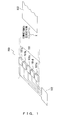
- A paper
thickness detecting apparatus 100 ofFIG. 1 is a general electrostatic capacitance paper thickness detecting apparatus. The paperthickness detecting apparatus 100 is provided with an electrostatic capacitance sensor (hereinafter, this sensor is referred to as "sensor array") 101 comprised ofcounter electrodes 101a-101e, and athickness detector 102 for detecting the thickness of a piece of paper from response signals in response to signals input into the sensor array 101 (,the input signals are common for each of thecounter electrodes 101a-101e). - Each of the
counter electrodes 101a-101e constitutes a capacitor with a predetermined electrostatic capacitance. Thethickness detector 102 receives response signals in response to common input signals (for example, sinusoidal signals) that are input to thecounter electrodes 101a-101e. Then, the thickness of a piece ofpaper 103 is detected from those response signals. The common input signals to be provided to thesensor array 101 are input from a signal source (not illustrated) to thesensor array 101. - When the
paper 103 is conveyed in a conveyance direction X and is inserted between the electrodes of therespective counter electrodes 101a-101e, the electrostatic capacitance of thecounter electrodes 101a-101e changes, as described above. At this time, the response signals change as illustrated inFIG. 2A andFIG. 2B . -
FIG. 2A andFIG. 2B are diagrams illustrating exemplary response signals when thepaper 103 is inserted between the electrodes of therespective counter electrodes 101a-101e. The horizontal axis ofFIG. 2A andFIG. 2B represents thecounter electrodes - As illustrated in
FIG. 2A , when thepaper 103 is inserted between the electrodes of thecounter electrodes 101a-101e, the signal of the counter electrode at which there is a fold on the paper increases sharply (for example, "a" illustrated inFIG. 2A ). - However, the electrostatic capacitance of the
counter electrodes 101a-101e also changes when a foreign object is adhered to the paper, and thereby similar response signals as inFIG. 2A are obtained, as illustrated in "b" ofFIG. 2B . - As described in the above, there has been a problem in which it is difficult to detect only a foreign object adhered to the paper as it is not possible to determine whether the change in the response signals is caused by folds in the paper or by a foreign object such as a piece of tape adhered to the paper.
- In relation to the above-mentioned technique,
Patent Document 1 discloses a paper thickness abnormality detection apparatus capable of detecting a thickness abnormality even when pieces of paper are fed at a high speed by performing a thickness abnormality detection with a detector having two or more condensers, and of speedily and accurately performing a detecting operation. -
Patent Document 2 discloses a paper discrimination apparatus capable of reforming the nonuniform electric field between electrodes by rounding or chamfering the end face of the electrodes on the sides where pieces of paper are conveyed and by covering the electrodes with dielectric material, and of reducing the change in electrostatic capacitance between the electrodes due to the up-down fluctuation of the paper when the paper is conveyed between the electrodes. -
Patent Document 3 discloses a paper discrimination sensor for discriminating the state of pieces of paper conveyed through a conveyance path by using the change in electrostatic capacitance between the counter electrodes arranged in the conveyance path of the paper, where a piece of tape or a seal can accurately and reliably be discriminated by forming the sensor body with the electrodes embedded onto the dielectric material and by providing a layer of conductive material whose surface resistance value is 104-109Ω on the surface of the sensor body on the sides where the paper pass through. - Patent Document 1: Japanese Patent Application No.
H02-098605 - Patent Document 2: Japanese Patent Application No.
2001-240271 - Patent Document 3: Japanese Patent Application No.
2004-280367 - The present invention has been made in view of the above-mentioned problems, and an object of the present invention is to provide a paper thickness detecting apparatus capable of reliably detecting a foreign object adhered to a piece of paper.
- In order to solve the above-mentioned problems, the paper thickness detecting apparatus is provided with a first sensor including a first applying electrode and a first detecting electrode that are opposed to each other, the first sensor being coupled to an electric current detection circuit for detecting electric current in the first detecting electrode; a second sensor including a second applying electrode and a second detecting electrode that are opposed to each other, the second sensor being coupled to an electric current detection circuit for detecting electric current in the second detecting electrode, the first applying electrode and the second applying electrode being arranged on opposite sides of the conveyance path; and a thickness detecting unit configured to obtain a first response signal detected by the electric current detection circuit of the first sensor and a second response signal detected by the electric current detection circuit of the second sensor, and to detect a change in the thickness of the paper due to a foreign object from a result of comparing the first response signal with the second response signal.
- According to the present invention, the thickness detecting unit obtains a first response signal from the first sensor and a second response signal from the second sensor. Then, the first response signal is compared with the second response signal.
- Here, the first sensor and the second sensor are arranged such that the first applying electrode and the second applying electrode are placed on opposites side of the conveyance path, and thus the directions of the electric lines of force against the paper conveyed through the sensors are not the same. Accordingly, the first response signals and the second response signals will be different signals when there are folds on the paper.
- Therefore, there will be an advantageous effect in which the folds on the paper and a foreign object adhered to the paper can be distinguished from each other by comparing the first response signal with the second response signal.
As described in the above, according to the present invention, a paper thickness detecting apparatus that can reliably detect a foreign object adhered to the paper can be provided. -
-
FIG. 1 is a diagram illustrating an exemplary conventional electrostatic capacitance paper thickness detecting apparatus. -
FIG. 2A is a diagram illustrating exemplary response signals when a piece of paper is inserted between the electrodes of respective counter electrodes ofFIG. 1 . -
FIG. 2B is a diagram illustrating exemplary response signals when a piece of paper is inserted between the electrodes of respective counter electrodes ofFIG. 1 . -
FIG. 3 is a diagram illustrating the operational principle of a paper thickness detecting apparatus according to an embodiment of the present invention. -
FIG. 4 is a diagram illustrating an exemplary specific configuration of a paper thickness detecting apparatus according to an embodiment of the present invention. -
FIG. 5 is a diagram illustrating an exemplary specific configuration of a first sensor array according to an embodiment of the present invention. -
FIG. 6 is a diagram illustrating a specific configuration of electric current detection circuits included in a first sensor array according to an embodiment of the present invention. -
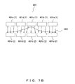
FIG. 7A is a diagram illustrating the change in electrostatic capacitance in a first sensor array according to an embodiment of the present invention. -
FIG. 7B is a diagram illustrating the change in electrostatic capacitance in a first sensor array according to an embodiment of the present invention. -
FIG. 8A is a diagram illustrating exemplary first response signals according to an embodiment of the present invention. -
FIG. 8B is a diagram illustrating exemplary second response signals according to an embodiment of the present invention. -
FIG. 9A is a diagram illustrating an exemplary map of first response signals according to an embodiment of the present invention. -
FIG. 9B is a diagram illustrating an exemplary map of second response signals according to an embodiment of the present invention. -
FIG. 9C is a diagram illustrating an exemplary determination result map according to an embodiment of the present invention. -
FIG. 10 is a diagram illustrating the first modification of a paper thickness detecting apparatus according to an embodiment of the present invention. -
FIG. 11 is a diagram illustrating the second modification of a paper thickness detecting apparatus according to an embodiment of the present invention. - Some embodiments will be described with reference to
FIG. 3-FIG.11 .
FIG. 3 is a diagram illustrating the operational principle of a paper thickness detecting apparatus according to an embodiment of the present invention.
A paperthickness detecting apparatus 300 ofFIG. 3 includes afirst sensor 301 and asecond sensor 302 in which the electrostatic capacitance changes when a piece ofpaper 304 such as a bank note or a piece of copying paper is inserted, and athickness detecting unit 303 for detecting the thickness of the piece ofpaper 304 from the signals respectively obtained from thefirst sensor 301 and the second sensor 302 (For example, a signal illustrated inFIG. 8A orFIG. 8B . Hereinafter, these signals are referred to as "response signals"). - The
first sensor 301 is constituted by two or more electrostatic capacitance sensors comprised of first applying electrodes and first detecting electrodes (hereinafter, these electrostatic capacitance sensors are referred to as "sensor") The first applying electrode may be constituted by a single common electrode. - The sensors of the
first sensor 301 include an electric current detection circuit for detecting the electric current in the first detecting electrodes. Hereinafter, the signals that are detected by the electric current detection circuits are referred to as "first response signals". - In the present embodiment, among the counter electrodes that constitute the sensors, the electrodes whose electric potential is oscillated by the signal source are defined as "applying electrodes". Then, the electrodes of the other side, i.e., the electrodes whose electric current is to be measured are defined as "detecting electrodes". The same applies to the following.
- The
second sensor 302 is constituted by two or more sensors that are comprised of second applying electrodes and second detecting electrodes. In a similar way as for the first applying electrodes, the second applying electrode may also be configured by a single common electrode. - In a similar way as for the
first sensor 301, the sensors of thesecond sensor 302 include an electric current detection circuit for detecting the electric current in the second detecting electrode. Hereinafter, the signals that are detected by this electric current detection circuit are referred to as "second response signals". - Then, the
first sensor 301 and thesecond sensor 302 are arranged such that a conveyance path a of the piece ofpaper 304 passes between the electrodes. Moreover, the first applying electrodes of thefirst sensor 301 and the second applying electrodes of thesecond sensor 302 are arranged such that they are placed on opposite sides of the conveyance path a. - Accordingly, as the piece of
paper 304 is conveyed along the conveying path a in an X direction, the piece ofpaper 304 firstly passes between the electrodes of thefirst sensor 301, and then passes between the electrodes of thesecond sensor 302. - The
thickness detecting unit 303 obtains the first response signals and the second response signals respectively from thefirst sensor 301 and thesecond sensor 302. Then, the first response signals and the second response signals are compared with each other, and it is determined whether the change in the thickness of the paper is due to a foreign object such as an adhered piece of tape or due to folds. - For example, the
thickness detecting unit 303 extracts signals at a predetermined level from the first response signals. In a similar manner, thethickness detecting unit 303 detects signals at a predetermined level from the second response signals. Then, the extracted signals are compared with each other. When the extracted signals match each other, it is determined that the extracted signals are due to a foreign object such as an adhered piece of tape (when the signals do not match each other, it is determined that the extracted signals are due to folds). - Furthermore, a signal source (not illustrated) is coupled to the sensors of the
first sensor 301 and the sensors of thesecond sensor 302, and provides a signal to the sensors. The input signal is common for the sensors of thesensor 301, and is also common for the sensors of thesecond sensor 302 respectively.
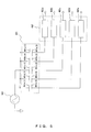
FIG. 4 is a diagram illustrating an exemplary specific configuration of a paperthickness detecting apparatus 300 according to the embodiments of the present invention. As illustrated inFIG. 4 , the paperthickness detecting apparatus 300 includes afirst sensor array 401 for detecting the change in electrostatic capacitance, a first electriccurrent detection circuit 402 for detecting first response signals, asecond sensor array 403 for detecting the change in electrostatic capacitance, a second electriccurrent detection circuit 404 for detecting second response signals, and athickness detecting unit 405 for detecting the thickness of the piece ofpaper 304 from the first and second response signals. - The
first sensor array 401 includes first applyingelectrodes 401a(1), 401b(1), ..., and 401e(1), and first detectingelectrodes 401a(2), 401b(2), ..., and 401e(2). - Hereinafter, the first applying
electrodes 401a(1), 401b (1), ..., and 401e(1) are collectively referred to as "first applying electrodes", and the first detectingelectrodes 401a(2), 401b(2), ..., and 401e(2) are collectively referred to as "first detecting electrodes". - The first applying
electrode 401a(1) and the first detectingelectrode 401a(2), the first applyingelectrode 401b(1) and the first detectingelectrode 401b(2), ..., and the first applyingelectrode 401e(1) and the first detectingelectrode 401e(2) are sensors, each of which constitutes a capacitor and is provided with a predetermined electrostatic capacitance. - The first electric
current detection circuit 402 is coupled to the first detecting electrodes to detect the electric current of the electrodes. In other words, the first electriccurrent detection circuit 402 obtains the first response signals from thefirst sensor array 401. Then, the first electriccurrent detection circuit 402 notifies thethickness detecting unit 405 of the obtained first response signals. - The
second sensor array 403 includes second applyingelectrodes 403a(1), 403b(1), ..., and 403e(1), and second detectingelectrodes 403a(2), 403b(2), ..., and 403e(2). - Hereinafter, the second applying electrode 403a(1), 403b(1), ..., and 403e(1) are collectively referred to as "second applying electrodes", and the second detecting electrode 403a(2), 403b(2), ..., and 403e(2) are collectively referred to as "second detecting electrodes".
- Then, the second applying electrode 403a(1) and the second detecting electrode 403a(2), the second applying
electrode 403b(1) and the second detectingelectrode 403b (2), ..., and the second applying electrode 403e(1) and the second detecting electrode 403e(2) are sensors, each of which constitutes a capacitor and is provided with a predetermined electrostatic capacitance. - The second electric
current detection circuit 404 is coupled to the second detecting electrodes to detect the electric current of the electrodes. In other words, the second electriccurrent detection circuit 404 obtains the second response signals from thesecond sensor array 403. Then, the second electriccurrent detection circuit 404 notifies thethickness detecting unit 405 of the obtained second response signals. - The
first sensor array 401 and thesecond sensor array 403 are arranged such that the conveyance path a of the piece ofpaper 304 passes between the electrodes.
Also, thefirst sensor array 401 and thesecond sensor array 403 are arranged such that the first applying electrodes are arranged above the conveyance path a while the second applying electrodes are arranged below the conveyance path a. - In other words, the
first sensor array 401 and thesecond sensor array 403 are arranged such that the first applying electrodes of thefirst sensor array 401 and the second applying electrodes of thesecond sensor array 403 are placed on opposite sides of the conveyance path a. - As described in the above, the
thickness detecting unit 405 obtains the first response signals and the second response signals respectively from the first electriccurrent detection circuit 402 and the second electriccurrent detection circuit 404. Then, signals at a level higher than a predetermined level are extracted from the first response signals and the second response signals, and the extracted signals are compared with each other. When the extracted signals match each other, it is determined that a foreign object such as a piece of tape is adhered to the piece of paper 304 (when the signals do not match each other, it is determined that there are folds on the piece of paper 304). - For the purpose of simplification it is not illustrated, but a signal source that provides an input signal such as a sinusoidal signal is coupled to the first applying electrodes of the
first sensor array 401 and the second applying electrodes of thesecond sensor array 403. - The piece of
paper 304 is conveyed in the conveyance path a in a conveyance direction X. As the piece ofpaper 304 can be conveyed by using the related art such as of holding and carrying the piece ofpaper 304 to the conveyance path by using two rollers, its details will be omitted. The piece ofpaper 304 that is conveyed through the conveyance path a passes between the electrodes of thefirst sensor array 401. Then, the piece ofpaper 304 is conveyed between the electrodes of thesecond sensor array 403. - In the above-described configuration, the
first sensor 301 ofFIG. 3 corresponds to thefirst sensor array 401 and the first electriccurrent detection circuit 402. Moreover, thesecond sensor 302 corresponds to thesecond sensor array 403 and the second electriccurrent detection circuit 404.
Furthermore, thethickness detecting unit 303 corresponds to thethickness detecting unit 405. - For the purpose of simplification, the first and second sensor arrays having five applying electrodes and five detecting electrodes are described in the above, but it should be understood that the number of the applying electrodes and the detecting electrodes are not to be limited.
-
FIG. 5 is a diagram illustrating an exemplary specific configuration of thefirst sensor array 401 according to the embodiment of the present invention.
As illustrated inFIG. 5 , in thefirst sensor array 401, the first applyingelectrode 401a(1) and the first detectingelectrode 401a(2), the first applyingelectrode 401b(1) and the first detectingelectrode 401b(2), ..., and the first applyingelectrode 401e(1) and the first detectingelectrode 401e(2) respectively constitute a capacitor. - A
signal source 501 is coupled to the respective first applyingelectrodes 401a(1), 401b(1), ..., and 401e(1), and provides a sinusoidal signal or the like.
The first detectingelectrodes 401a(2), 401b(2), ..., and 401e(2) are respectively coupled to electriccurrent detection circuits current detection circuit 402. The signals that are detected at the respective electriccurrent detection circuits thickness detecting unit 405. - In
FIG. 5 , the exemplary specific configuration of only thefirst sensor array 401 is described, but thesecond sensor array 403 is configured in a similar manner.
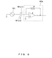
FIG. 6 is a diagram illustrating a specific configuration of the electriccurrent detection circuit 402a-402e included in thefirst sensor array 401 according to the embodiment of the present invention.FIG. 6 illustrates an exemplary configuration of only the electriccurrent detection circuit 402a, but the other electriccurrent detection circuits 402b-402e are also configured in a similar manner. - As illustrated in
FIG. 6 , thedetection circuit 402a is an electric current voltage conversion circuit which includes a resistance R and an operational amplifier A, and is coupled to a capacitor C comprised of a first applyingelectrode 401a(1) and a first detectingelectrode 401a(2) at an input. This configuration may be referred to as a self-balancing bridge circuit. - It is to be noted that the
detection circuit 402a is not limited to the circuit illustrated inFIG. 6 . For example, thedetection circuit 402 may be configured in a different manner as long as it is capable of obtaining the first response signals by measuring the electric current in the first detectingelectrode 401a(1). - Here, the change in electrostatic capacitance when the piece of
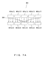
paper 304 having a fold is inserted into thefirst sensor array 401 will be described with reference toFIG. 7A andFIG. 7B .FIG. 7A andFIG. 7B are diagrams illustrating cross-sectional view of thefirst sensor array 401, which represent the vertical surface to the conveyance direction x. -
FIG. 7A schematically illustrates the electric lines of force of thefirst sensor array 401 when the convex portion of the fold of the piece ofpaper 304 is at the first detecting electrode side. A phenomenon is caused in which the electric lines of force are gathered to the portion of the piece ofpaper 304 where the permittivity is larger than the air. Accordingly, when the convex portion of the fold is facing the first detecting electrode side, the electric lines of force from the first applying electrodes are gradually gathered to the convex portion, and are input into the first detecting electrodes just as gathered. - The electric current in the first detecting electrodes is determined by the charge amount induced on the first detecting electrodes, i.e., the number of the electric lines of force that are input into the first detecting electrodes (integration of electric field). In
FIG. 7A , the electric lines of force are gathered to the vicinity of the convex portion, and thereby the electric current of the first detectingelectrode 401c(2) around the convex portion becomes larger. Accordingly, for example, a response signal B ofFIG. 8A is obtained. - On the other hand,
FIG. 7B schematically illustrates the electric lines of force of thefirst sensor array 401 when the convex portion of the fold of the piece ofpaper 304 is at the first applying electrode side. As described in the above, a phenomenon is caused in which the electric lines of force are gathered to the portion of the piece ofpaper 304 where the permittivity is larger than the air, and thus the electric lines of force from the first applying electrodes are dispersed from the top of the fold towards the edges of the paper away from the fold and input into the first detecting electrodes. Accordingly, the electric lines of force around the convex portion are dispersed, and thereby the electric current of the first detectingelectrode 401c(2) around the convex portion becomes smaller. Accordingly, for example, a response signal B ofFIG. 8B is obtained. - Here, if a piece of tape is adhered to the piece of
paper 304, it means that a substance whose relative permittivity is larger than 1 is adhered to the piece ofpaper 304. Accordingly, the electric current increases at the position to which the piece of tape is adhered regardless of whether the piece of tape is adhered to the surface of the first applying electrode side or the surface of the first detecting electrode side. Accordingly, for example, a response signal A ofFIG. 8A orFIG. 8B is obtained. -
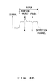
FIG. 8A andFIG. 8B are diagrams illustrating exemplary first response signals that are detected by thefirst sensor array 401 and second response signals that are detected by thesecond sensor array 403, according to the embodiments of the present invention. As the horizontal axis of the graph representing detection channels, the graph should actually be a discrete graph on which the electric current for each detection channel is plotted. However, for the purpose of simplification, it is illustrated with a continuous solid line. - The response signals illustrated in
FIG. 8A andFIG. 8B indicate the response signals of when the piece ofpaper 304 having a convex portion of the fold and a foreign object such as a piece of tape on the first detecting electrode side is inserted through thefirst sensor array 401 and thesecond sensor array 403. -
FIG. 8A illustrates the first response signals. As the foreign object such as a piece of tape is adhered to the paper, the electric current of the first detecting electrodes at the positions of the piece of tape is increased, and thereby a response signal A is obtained. In thefirst sensor array 401, the convex portion of the fold of the piece ofpaper 304 is at the first detecting electrode side, and thus the state becomes likeFIG. 7A . Accordingly, the electric current of the first detecting electrodes around the convex portion increases, and thereby a response signal B is obtained. -
FIG. 8B illustrates the second response signals. As the foreign object such as a piece of tape is adhered to the paper, the electric current of the second detecting electrodes at the positions of the piece of tape is increased, and thereby a response signal A is obtained. In thesecond sensor array 403, the convex portion of the fold of the piece ofpaper 304 is at the second applying electrode side, and thus the state becomes likeFIG. 7B . Accordingly, the electric current of the second detecting electrodes around the convex portion decreases, and thereby a response signal B is obtained. - In the
thickness detecting apparatus 300 according to the present embodiment, thethickness detecting unit 405 stores response signals of when thepaper 304 is conveyed through thefirst sensor array 401 and thesecond sensor array 403. Then, thethickness detecting apparatus 300 generates a map of the first response signals (map illustrated inFIG. 9A ) and a map of the second response signals (map illustrated inFIG. 9B ), and generates a determination result map from the two generated maps to detect a foreign object. The specific processing of thethickness detecting unit 405 is listed below. -
- (1) First and second response signals are begun to be obtained.
- (2) A first response signal is obtained. The time at which the first response signal is obtained for the first time is defined as t1.
- (3) The first response signal is compared with a signal level that corresponds to the thickness of the piece of paper 304 (hereinafter, this signal level is referred to as a "first threshold"), and thereby a signal of the piece of
paper 304 is extracted. Then, the extracted signal is stored in a storage unit or the like (not illustrated). -
- (4) The extracted signal in process (3) is compared with a signal level corresponding to folds or a foreign object (hereinafter, they are referred to as "folds or the like") on the piece of paper 304 (hereinafter, this signal level is referred to as a "second threshold"), and thereby a signal of the portion of folds or the like of the piece of
paper 304 is extracted. Then, the extracted signal is stored in a storage unit or the like. In the present embodiment, a signal level of 1.5 times the first threshold is used as the second threshold. -
- (5) A second response signal is obtained. The time at which the second response signal is obtained for the first time is defined as t2.
- (6) The second signal is compared with the first threshold, and thereby a signal of the piece of
paper 304 is extracted. Then, the extracted signal is stored in a storage unit or the like. -
- (7) The signal extracted in process (6) is compared with the second threshold, and thereby a signal of the portion of folds or the like of the piece of
paper 304 is extracted. Then, the extracted signal is stored in a storage unit or the like. - (8) Processes (2)-(4) are repeated while the first response signals are being detected, and processes (5)-(7) are repeated while the second response signals are being detected.
- By performing the above processing, the map of the first response signals (hereinafter, this map is referred to as a "first response signal map") illustrated in
FIG. 9A and the map of the second response signals (hereinafter, this map is referred to as a "second response signal map") illustrated inFIG. 9B are generated. - In
FIG. 9A andFIG. 9B , dotted area p represents signals larger than the first threshold, and diagonally shaded area q represent signals larger than the second threshold. Accordingly, the diagonally shaded area q indicates an area in which the thickness has changed due to folds or a foreign object such as a piece of tape on the piece ofpaper 304. -
- (9) Once processes (2)-(7) are completed, the first response signal map and the second response signal map are compared with each other. Then, signals that exceed the second threshold in both maps are extracted so as to generate a map (hereinafter, this map is referred to as a "determination result map").
- The obtainment starting time t1 in the first response signal map and the obtainment starting time t2 in the second response signal map are different from each other, so the maps should be compared with each other upon adjusting the time of the second response signal map by t2-t1.
-
- (10) The determination result map illustrated in
FIG. 9C is obtained by processing (9). Then, black-painted area r in the map is determined to correspond to a foreign object such as a piece of tape adhered to the piece ofpaper 304.
In the above embodiment, thefirst sensor array 401 in which the first applyingelectrode 401a(1) and first detectingelectrode 401a(2), the first applyingelectrode 401b(1) and first detectingelectrode 401b(2), ..., and the first applyingelectrode 401e(1) and the first detectingelectrode 401e(2) respectively constitute a capacitor are described as an example, but as is apparent from the description ofFIG. 7A andFIG. 7B , the first applying electrodes may be a single common electrode. - Similarly, the
second sensor array 403 in which the second applying electrode 403a(1) and second detecting electrode 403a(2), the second applyingelectrode 403b(1) and second detectingelectrode 403b(2), ..., and the second applying electrode 403e(1) and second detecting electrode 403e(2) respectively constitute a capacitor are described as an example, but the second applying electrodes may be a single common electrode. Such exemplary configurations will be described. -
FIG. 10 is a diagram illustrating the first modification of the paperthickness detecting apparatus 300 according to the embodiments of the present invention.
A paperthickness detecting apparatus 1000 illustrated inFIG. 10 includes afirst sensor 1001 and asecond sensor 1002 for detecting the change in electrostatic capacitance, the first electriccurrent detection circuit 402 for detecting first response signals, the second electriccurrent detection circuit 404 for detecting the second response signals, and thethickness detecting unit 405 for detecting the thickness of the piece ofpaper 304 from the first and second response signals. It is to be noted that first guard electrodes 1001(2) and 101(3) and second guard electrodes 102 (2) and 102 (3) are not essential elements. - The
first sensor 1001 includes a first applying electrode 1001(1), first detectingelectrodes 401a(2), 401b(2), ..., and 401e(2), and first guard electrodes 1001(2) and 1001(3). - The first applying electrode 1001(1) is the common applying electrode for the first detecting
electrodes 401a (2), 401b(2), ..., and 401e(2), and for the first guard electrodes 1001(2) and 1001(3). - The size of the first applying electrode 1001(1) is equal to the sum of the sizes of the first detecting
electrodes 401a (2), 401b(2), ..., and 401e(2), and the sizes of the first guard electrodes 1001 (2) and 1001 (3). In the case of not using the first guard electrodes 1001 (2) and 1001 (3), the size of the first applying electrode 1001 (1) may be equal to the sum of the sizes of the first detectingelectrodes 401a(2), 401b(2), ... and 401e(2). - In this case, the first applying electrode 1001(1) and the first detecting
electrodes 401a(2), 401b(2), ..., and 401e(2) respectively constitute a capacitor, and are provided with predetermined electrostatic capacitance. - The first detecting
electrodes 401a(2), 401b (2), ..., and 401e(2) lie between the first guard electrode 1001(2) and the first guard electrode 1001(3). Moreover, the first guard electrode 1001(2) and the first guard electrode 1001(3) are coupled to the same electric potential as that of the first detecting electrodes (for example, 0V). - By having the first guard electrodes 1001(2) and 1001(3), the phenomenon in which the electric lines of force spread beyond the counter electrodes may be prevented from occurring. For example, if there is nothing between the electrodes, the electric lines of force are input from the first applying electrode 1001(1) vertically to the respective first detecting
electrodes 401a(2), 401b(2), ..., and 401e(2). - Accordingly, the electric lines of force can be prevented from spreading between the counter electrodes. Thus, response signals that do not depend on the position of the piece of
paper 304 between the counter electrodes can be obtained.
Thesecond sensor 1002 includes a second applying electrode 1002(1), second detectingelectrodes 403a(2), 403b(2), ..., and 403e(2), and first guard electrodes 1002(2) and 1002(3). - The second applying electrode 1002(1) is the common applying electrode for the second detecting
electrodes 403a(2), 403b(2), ..., and 403e(2), and for the second guard electrodes 1002(2) and 1002(3). - The size of the second applying electrode 1002 (1) is equal to the sum of the sizes of the second detecting
electrodes 403a(2), 403b(2), ..., and 403e (2) and the sizes of the second guard electrodes 1002 (2) and 1002(3). In the case of not using the second guard electrodes 1002(2) and 1002(3), the size of the second applying electrode 1002(1) may be equal to the sum of the sizes of the second detectingelectrodes 403a(2), 403b(2), ... and 403e(2). - In this case, the second applying electrode 1002(1) and the second detecting
electrodes 403a (2), 403b(2), ..., and 403e(2) respectively constitute a capacitor, and are provided with predetermined electrostatic capacitance. - The second detecting
electrodes 403a (2), 403b (2), ..., and 403e (2) lie between the second guard electrode 1002 (2) and the second guard electrode 1002 (3). Moreover, the second guard electrode 1002(2) and the second guard electrode 1002(3) are coupled to the same electric potential as that of the second detecting electrodes (for example, 0V). - The phenomenon in which the electric lines of force spread beyond the counter electrodes may be prevented from occurring in the same way as in the
first sensor 1001, which does so by having the second guard electrodes 1002(2) and 1002(3). As a result, the electric lines of force can be prevented from spreading between the counter electrodes, and thus response signals that do not depend on the position of the piece ofpaper 304 between the counter electrodes can be obtained. - In the above described embodiments and the first modification, the cases of using two sensor arrays (the
first sensor array 401 and the second sensor array 403) or sensors (thefirst sensor 1001 and the second sensor 1002) are described as examples, but only one sensor array may also be used. Such an exemplary configuration will be described. -
FIG. 11 is a diagram illustrating the second modification of the paperthickness detecting apparatus 300 according to the embodiments of the present invention.
A paperthickness detecting apparatus 1100 ofFIG. 11 includes asensor array 1101 for detecting the change in electrostatic capacitance, a first electriccurrent detection circuit 402 for detecting first response signals, a second electriccurrent detection circuit 404 for detecting second response signals, and athickness detecting unit 405 for detecting the thickness of the piece ofpaper 304 from the first and second response signals. - The
sensor array 1101 includes the first detectingelectrodes 401a (2), 401b (2), ..., and 401e(2), and the second detectingelectrodes 403a(2), 403b(2), ..., and 403e(2) - Moreover, the first detecting
electrode 401a(2) and the second detecting electrode 403a(2), the first detectingelectrode 401b(2) and the second detectingelectrode 403b (2), ..., and the first detectingelectrode 401e (2) and the second detecting electrode 403e(2) respectively constitute a capacitor, and are provided with a predetermined electrostatic capacitance. - Here, assuming that the second detecting
electrodes 403a(2), 403b(2), ..., and 403e(2) are the first applyingelectrodes 401a(1), 401b(1), ..., and 401e(1), the configuration becomes equal to thefirst sensor array 401 ofFIG. 4 . - Moreover, assuming that the first detecting
electrodes 401a(2), 401b(2), ..., and 401e(2) are the second applyingelectrodes 403a(1), 403b(1), ..., and 403e(1), the configuration becomes equal to thesecond sensor array 403 ofFIG. 4 . - Accordingly, the first response signals and the second response signals can be obtained by alternately applying an input signal to the second sensor array and the first sensor array for a certain interval, and by alternately obtaining response signals from the first detecting electrodes and the second detecting electrodes.
- As described in the above, the paper
thickness detecting apparatus 300 obtains the first response signals from thefirst sensor array 401, and obtains the second response signals from thesecond sensor array 403. Then, the first response signals and the second response signals are compared with each other. - Here, the
first sensor array 401 and thesecond sensor array 403 are arranged such that the first applying electrodes of thefirst sensor array 401 and the second applying electrodes of thesecond sensor array 403 are placed on opposite sides of the conveyance path a. Accordingly, if a common input signal is provided to both sensor arrays, the direction of electric lines of force for the piece ofpaper 304 passing through thefirst sensor array 401 becomes opposite to the direction of electric lines of force for the piece ofpaper 304 passing through thesecond sensor array 403. - When there are folds on the piece of
paper 304, the electrostatic capacitance of the capacitors changes depending on the direction of the electric lines of force towards the piece ofpaper 304, and thereby the first response signals and the second response signals will be different from each other. - Accordingly, by comparing the first response signals with the second response signals, the change in the signals due to folds on the piece of
paper 304 can be removed, and the change in the signals due to a foreign object such as a piece of tape adhered to the piece ofpaper 304 can be extracted. - As a result, it is possible to determine whether or not a foreign object such as a piece of tape is adhered to the piece of
paper 304. For the same reason, the same effect can be obtained for the first modification or the second modification, as in thedetection apparatus 300.
Claims (9)
- A paper thickness detecting apparatus for detecting a thickness of a piece of paper conveyed through a conveyance path from a change in electrostatic capacitance of a sensor having opposing electrodes, the sensor being arranged such that the conveyance path of the paper passes between the electrodes, the paper thickness detecting apparatus comprising:a first sensor including a first applying electrode and a first detecting electrode that are opposed to each other, the first sensor being coupled to an electric current detection circuit for detecting electric current in the first detecting electrode;a second sensor including a second applying electrode and a second detecting electrode that are opposed to each other, the second sensor being coupled to an electric current detection circuit for detecting electric current in the second detecting electrode, the first applying electrode and the second applying electrode being arranged on opposite sides of the conveyance path; anda thickness detecting unit configured to obtain a first response signal detected by the electric current detection circuit of the first sensor and a second response signal detected by the electric current detection circuit of the second sensor, and to detect a change in the thickness of the paper due to a foreign object from a result of comparing the first response signal with the second response signal.
- The paper thickness detecting apparatus according to claim 1, wherein
the first detecting electrode of the first sensor and the second detecting electrode of the second sensor each comprise a plurality of electrodes. - The paper thickness detecting apparatus according to claim 1, wherein
the first applying electrode of the first sensor and the second applying electrode of the second sensor each comprise a single electrode. - The paper thickness detecting apparatus according to claim 1, wherein
the thickness detecting unit compares a portion of the first response signal exceeding a predetermined level with a portion of the second response signal exceeding the predetermined level, and determines that a foreign object is adhered to the paper when the portions match each other or approximately match each other as a result of the comparing. - The paper thickness detecting apparatus according to claim 1, wherein
the thickness detecting unit compares a portion of the first response signal exceeding a predetermined level with a portion of the second response signal exceeding the predetermined level, and determines that there is a fold on the paper when the portions do not match each other or do not approximately match each other as a result of the comparing. - A paper thickness detecting apparatus for detecting a thickness of a piece of paper conveyed through a conveyance path from a change in electrostatic capacitance of a sensor having opposing electrodes, the sensor being arranged such that the conveyance path of the paper passes between the electrodes, the paper thickness detecting apparatus comprising:a sensor including a first electrode and a second electrode that are opposed to each other, the sensor being coupled to a first electric current detection circuit for detecting electric current in the first electrode, and being coupled to a second electric current detection circuit for detecting electric current in the second electrode;a thickness detecting unit configured to alternately obtain a first response signal detected by the first electric current detection circuit and a second response signal detected by the second electric current detection circuit for every certain interval, and to detect a change in the thickness of the paper due to a foreign object from a result of comparing the first response signal with the second response signal.
- The paper thickness detecting apparatus according to claim 6, wherein
the first detecting electrode of the sensor and the second detecting electrode of the sensor each comprise a plurality of electrodes. - The paper thickness detecting apparatus according to claim 6, wherein
the thickness detecting unit compares a portion of the first response signal exceeding a predetermined level with a portion of the second response signal exceeding the predetermined level, and determines that a foreign object is adhered to the paper when the portions match each other or approximately match each other as a result of the comparing. - The paper thickness detecting apparatus according to claim 6, wherein
the thickness detecting unit compares a portion of the first response signal exceeding a predetermined level with a portion of the second response signal exceeding the predetermined level, and determines that there is a fold on the paper when the portions do not match each other or do not approximately match each other as a result of the comparing.
Applications Claiming Priority (1)
| Application Number | Priority Date | Filing Date | Title |
|---|---|---|---|
| PCT/JP2007/000799 WO2009013787A1 (en) | 2007-07-26 | 2007-07-26 | Paper sheet thickness detection device |
Publications (3)
| Publication Number | Publication Date |
|---|---|
| EP2174899A1 true EP2174899A1 (en) | 2010-04-14 |
| EP2174899A4 EP2174899A4 (en) | 2014-06-11 |
| EP2174899B1 EP2174899B1 (en) | 2017-12-27 |
Family
ID=40281051
Family Applications (1)
| Application Number | Title | Priority Date | Filing Date |
|---|---|---|---|
| EP07790293.0A Not-in-force EP2174899B1 (en) | 2007-07-26 | 2007-07-26 | Paper sheet thickness detection device |
Country Status (6)
| Country | Link |
|---|---|
| US (2) | US8028990B2 (en) |
| EP (1) | EP2174899B1 (en) |
| JP (1) | JP4755283B2 (en) |
| KR (1) | KR101115779B1 (en) |
| CN (1) | CN101754919B (en) |
| WO (1) | WO2009013787A1 (en) |
Cited By (4)
| Publication number | Priority date | Publication date | Assignee | Title |
|---|---|---|---|---|
| EP3082113A4 (en) * | 2013-12-12 | 2016-11-30 | Grg Banking Equipment Co Ltd | Method and system for recognizing bill with abnormal thickness |
| EP3082112A4 (en) * | 2013-12-12 | 2016-12-07 | Grg Banking Equipment Co Ltd | Method and device for banknote identification based on thickness signal identification |
| RU2721099C1 (en) * | 2019-12-26 | 2020-05-15 | Общество С Ограниченной Ответственностью "Конструкторское Бюро "Дорс" (Ооо "Кб "Дорс") | Device for detecting inhomogeneity with sharp boundaries of a thin object, and a method for use thereof |
| EP4008657A1 (en) * | 2020-12-01 | 2022-06-08 | Tetra Laval Holdings & Finance S.A. | A method for detecting and tracking a feature of a web of packaging material |
Families Citing this family (66)
| Publication number | Priority date | Publication date | Assignee | Title |
|---|---|---|---|---|
| FR2944718B1 (en) * | 2009-04-28 | 2011-04-01 | Solystic | METHOD FOR DETECTING OPEN POSTAL ENTRIES SUCH AS MAGAZINES WITHOUT ENVELOPE |
| RU2507586C2 (en) * | 2009-10-01 | 2014-02-20 | Де Ля Рю Интернэшнл Лимитед | Apparatus and method of detecting thickness of sheet document |
| CN102207720B (en) * | 2010-03-29 | 2014-07-02 | 株式会社东芝 | Image erasing apparatus and method of determining foreign matter attached to recording medium supplied to image erasing apparatus |
| CN101996433B (en) * | 2010-09-21 | 2012-10-03 | 广州广电运通金融电子股份有限公司 | Thickness identification device of slice-type medium and identification method thereof |
| US8496245B2 (en) * | 2011-09-26 | 2013-07-30 | Burroughs, Inc. | Double document detection apparatus and a method for conducting the same |
| ITFI20110214A1 (en) | 2011-10-05 | 2013-04-06 | Actis Active Sensors S R L | "METHOD AND DEVICE FOR DETECTION OF MATERIALS WITH CERTAIN OPTICAL CHARACTERISTICS OVERLAPPED TO A MATERIAL OF DIFFERENT OPTICAL CHARACTERISTICS" |
| RU2483276C1 (en) * | 2011-12-28 | 2013-05-27 | Общество С Ограниченной Ответственностью "Конструкторское Бюро "Дорс" (Ооо "Кб "Дорс") | Method for detection of sheet irregularities and device for its realisation |
| US8854056B1 (en) * | 2012-09-13 | 2014-10-07 | Cypress Semiconductor Corporation | Capacitance sensing devices and methods |
| JP6135139B2 (en) * | 2013-01-17 | 2017-05-31 | セイコーエプソン株式会社 | Liquid ejection device |
| CN203882369U (en) | 2013-08-12 | 2014-10-15 | 起山电子株式会社 | Bill thickness detecting apparatus |
| CN103673961B (en) * | 2013-12-12 | 2016-05-11 | 广州广电运通金融电子股份有限公司 | A kind of laminated dielectric thickness detection apparatus and method |
| EP2923957A1 (en) * | 2014-03-26 | 2015-09-30 | UHLMANN PAC-SYSTEME GmbH & Co. KG | Device for adapting the control of a system for processing foil webs |
| CN103925867A (en) * | 2014-04-29 | 2014-07-16 | 威海华菱光电股份有限公司 | Thickness sensor and thickness measuring method |
| CN103929562B (en) * | 2014-04-29 | 2017-08-01 | 威海华菱光电股份有限公司 | Imaging sensor, image scanning and thickness detecting method |
| CN103985189A (en) * | 2014-05-13 | 2014-08-13 | 威海华菱光电股份有限公司 | Device for measuring thickness of banknote |
| CN103971445A (en) * | 2014-05-13 | 2014-08-06 | 威海华菱光电股份有限公司 | Paper money thickness detecting device |
| CN103971446A (en) * | 2014-05-13 | 2014-08-06 | 威海华菱光电股份有限公司 | Paper money thickness detecting tool |
| CN103996238B (en) * | 2014-05-16 | 2016-03-23 | 威海华菱光电股份有限公司 | Thin slice pick-up unit and image read-out |
| CN103996236B (en) * | 2014-05-16 | 2017-08-01 | 威海华菱光电股份有限公司 | Thin slice detection means and image read-out |
| CN103996237B (en) * | 2014-05-16 | 2017-01-11 | 威海华菱光电股份有限公司 | Sheet detection device and image reading device |
| CN103968749A (en) * | 2014-05-16 | 2014-08-06 | 威海华菱光电股份有限公司 | Object thickness detection device and detection method thereof |
| CN104049003A (en) * | 2014-06-10 | 2014-09-17 | 中国人民银行印制科学技术研究所 | Array-capacitor inductive sensor and negotiable-securities anti-counterfeit detection method |
| US9508208B1 (en) * | 2014-07-25 | 2016-11-29 | Cummins Allison Corp. | Systems, methods and devices for processing coins with linear array of coin imaging sensors |
| KR101758366B1 (en) | 2015-02-25 | 2017-07-19 | 기산전자 주식회사 | Apparatus for discriminating paper money using rf |
| WO2016170639A1 (en) * | 2015-04-23 | 2016-10-27 | 富士通フロンテック株式会社 | Sensor for detecting thickness of paper sheets, and banknote-differentiating unit |
| CN104802514B (en) * | 2015-05-13 | 2017-12-22 | 广州广电运通金融电子股份有限公司 | A kind of flaky medium detection means of surface mount foreign matter |
| US10613243B2 (en) * | 2017-04-27 | 2020-04-07 | Franklin Sensors Inc. | Apparatus and methods for obscured feature detection |
| US10663613B2 (en) | 2015-06-23 | 2020-05-26 | Franklin Sensors, Inc. | Apparatus and methods for detecting obscured features |
| US10261208B2 (en) | 2015-06-23 | 2019-04-16 | David M. Dorrough | Apparatus and methods for detecting obscured features |
| US10895657B2 (en) | 2017-01-13 | 2021-01-19 | Franklin Sensors Inc. | Apparatus and methods for obscured feature detection with uniform electric fields |
| CN105172388A (en) * | 2015-08-13 | 2015-12-23 | 陈超 | Capacitive printing paper detection apparatus |
| CN105136011B (en) * | 2015-09-30 | 2018-09-14 | 威海华菱光电股份有限公司 | The detection device of film thickness |
| CN105136012A (en) * | 2015-09-30 | 2015-12-09 | 威海华菱光电股份有限公司 | Detection apparatus of film thickness |
| CN105318819B (en) * | 2015-11-04 | 2018-09-18 | 威海华菱光电股份有限公司 | The detection device of film thickness |
| JP2017088270A (en) * | 2015-11-04 | 2017-05-25 | ニスカ株式会社 | Sheet transport device, image formation device, and sheet post-processing device |
| CN105318820A (en) * | 2015-11-05 | 2016-02-10 | 威海华菱光电股份有限公司 | Thickness sensor |
| CN105333809A (en) * | 2015-12-04 | 2016-02-17 | 威海华菱光电股份有限公司 | Thickness detecting sensor |
| CN105674871A (en) * | 2016-04-01 | 2016-06-15 | 威海华菱光电股份有限公司 | Film thickness detection device |
| CN105931360B (en) * | 2016-04-01 | 2019-04-09 | 威海华菱光电股份有限公司 | The detection device of film thickness |
| CN106091910B (en) * | 2016-05-26 | 2018-05-25 | 威海华菱光电股份有限公司 | The detection device of film thickness |
| CN106412465A (en) * | 2016-06-14 | 2017-02-15 | 威海华菱光电股份有限公司 | Image sensor |
| CN105937874A (en) * | 2016-07-01 | 2016-09-14 | 杭州空灵智能科技有限公司 | Paper sheet thickness measurement structure |
| CN106097553B (en) * | 2016-08-10 | 2019-04-09 | 威海华菱光电股份有限公司 | Thickness detection apparatus |
| CN106441067B (en) * | 2016-08-31 | 2019-06-04 | 威海华菱光电股份有限公司 | Thickness detection apparatus and method |
| CN106352783B (en) * | 2016-08-31 | 2020-07-03 | 威海华菱光电股份有限公司 | Thickness detection device |
| JP6711728B2 (en) * | 2016-09-16 | 2020-06-17 | 日立オムロンターミナルソリューションズ株式会社 | Paper handling equipment |
| US10347068B2 (en) * | 2016-09-26 | 2019-07-09 | Mitsubishi Electric Corporation | Capacitance detection device and image reading device |
| US10282932B2 (en) | 2016-09-26 | 2019-05-07 | Mitsubishi Electric Corporation | Capacitance detection device and image reading device |
| JP2018090344A (en) * | 2016-11-30 | 2018-06-14 | コニカミノルタ株式会社 | Paper conveying device, image forming device, method for estimating basis weight of paper, and program for estimating basis weight of paper |
| US10502541B2 (en) | 2016-12-16 | 2019-12-10 | Climax Machine Industry Co., Ltd. | Device for detecting thickness and thickness variation of a sheetlike object |
| JP6939048B2 (en) * | 2017-04-24 | 2021-09-22 | コニカミノルタ株式会社 | Residual paper judgment device |
| CN107393116B (en) * | 2017-07-06 | 2023-04-25 | 得力集团有限公司 | Cash inspecting machine and cash inspecting method and circuit structure thereof |
| CN107607595B (en) * | 2017-09-21 | 2020-05-12 | 京东方科技集团股份有限公司 | Optical filter detection device and method |
| US10160614B1 (en) * | 2017-10-26 | 2018-12-25 | Ncr Corporation | Banknote foreign object detection using pressure sensing array |
| CN111602178B (en) * | 2018-01-11 | 2022-03-11 | 三菱电机株式会社 | Image reading apparatus |
| JP7081308B2 (en) * | 2018-05-29 | 2022-06-07 | 株式会社リコー | Position detection device, position detection method and image forming device |
| CN109115103B (en) * | 2018-07-27 | 2020-11-06 | 威海华菱光电股份有限公司 | Detection device and detection method of thin film |
| CN115932977A (en) * | 2018-12-05 | 2023-04-07 | 三菱电机株式会社 | Capacitance detection device and image reading device |
| CN109677121B (en) * | 2018-12-19 | 2022-10-21 | 森大(深圳)技术有限公司 | Jet printing height control method, device, equipment and medium applied to PCB |
| CN112639393B (en) * | 2018-12-28 | 2021-10-15 | 深圳市柔宇科技股份有限公司 | Pair thickness recognition device, bundle thickness recognition method and handwriting input device |
| CN110425973A (en) * | 2019-08-29 | 2019-11-08 | 威海华菱光电股份有限公司 | Thickness detection apparatus, method, system, storage medium and processor |
| CN110823260B (en) * | 2019-10-16 | 2021-11-16 | 杭州师范大学钱江学院 | Paper quantity detection device based on capacitive sensor and quantity detection method thereof |
| KR20210121759A (en) * | 2020-03-31 | 2021-10-08 | 휴렛-팩커드 디벨롭먼트 컴퍼니, 엘.피. | Capacitance based paper detection |
| SE545420C2 (en) * | 2021-12-22 | 2023-09-05 | Stora Enso Oyj | A method to determine thickness and wave height of a thin substrate |
| TWI812317B (en) * | 2022-06-30 | 2023-08-11 | 金寶電子工業股份有限公司 | Paper detection device |
| CN116750564B (en) * | 2023-08-22 | 2023-10-27 | 常州登鑫高分子材料科技有限公司 | Coiled material conveying mechanism and compound bonding equipment |
Citations (2)
| Publication number | Priority date | Publication date | Assignee | Title |
|---|---|---|---|---|
| US5198777A (en) * | 1990-02-14 | 1993-03-30 | Murata Mfg. Co., Ltd. | Paper thickness detecting apparatus having a resonator with a resonance point set by a capacitance detecting unit |
| US5321366A (en) * | 1992-08-31 | 1994-06-14 | Murata Mfg. Co. Ltd. | Capacitance sensor apparatus of divided multi-electrode type |
Family Cites Families (19)
| Publication number | Priority date | Publication date | Assignee | Title |
|---|---|---|---|---|
| US4113105A (en) * | 1977-03-07 | 1978-09-12 | Docutronix, Inc. | Device for checking envelopes for enclosed documents |
| FR2528970B1 (en) * | 1982-06-22 | 1985-09-27 | Flonic Sa | DEVICE FOR CHECKING THICKNESS OF DIELECTRIC SHEET MATERIAL |
| JPS59131104A (en) * | 1983-01-17 | 1984-07-27 | Fuji Electric Co Ltd | Identifying device for paper sheet or the like |
| JPS6188387A (en) * | 1984-10-06 | 1986-05-06 | 富士電機株式会社 | Sheet paper discriminator |
| JPH028702A (en) * | 1988-06-27 | 1990-01-12 | Ono Sokki Co Ltd | Thickness measuring apparatus for semi-insulator |
| JP2814087B2 (en) | 1988-10-05 | 1998-10-22 | 古野電気株式会社 | Paper thickness abnormality detection device |
| JPH0752083B2 (en) * | 1990-02-16 | 1995-06-05 | 株式会社村田製作所 | Paper thickness detector |
| JPH0436457A (en) * | 1990-05-31 | 1992-02-06 | Sumitomo Metal Ind Ltd | Production of carburized and case hardened steel for shot peening |
| JPH0436456A (en) * | 1990-06-01 | 1992-02-06 | Nippon Steel Corp | Production of martensitic 13%cr stainless steel excellent in stress corrosion cracking resistance |
| US5035415A (en) * | 1990-07-16 | 1991-07-30 | Eastman Kodak Company | System for detecting the accurate positioning of sheets along a feed path by using capacitors as sensors |
| US5076566A (en) * | 1990-07-16 | 1991-12-31 | Eastman Kodak Company | Self-calibrating system for detecting media movement by using capacitors as sensors |
| JPH07113525B2 (en) * | 1990-07-20 | 1995-12-06 | 株式会社村田製作所 | Electrostatic detection device for paper sheets |
| US5168239A (en) * | 1990-10-15 | 1992-12-01 | Teknekron Communications Systems, Inc. | Method and apparatus for adjusting the threshold for determining the thickness of or the number of sheets in a sheet material |
| JPH04279801A (en) * | 1991-03-08 | 1992-10-05 | Murata Mfg Co Ltd | Sheetlike medium static electricity detection electrode |
| JPH0599605A (en) * | 1991-10-09 | 1993-04-23 | Murata Mfg Co Ltd | Non-contact type thickness detection unit |
| JP3755798B2 (en) | 2000-03-03 | 2006-03-15 | グローリー工業株式会社 | Paper sheet discrimination device |
| JP4292015B2 (en) | 2003-03-14 | 2009-07-08 | グローリー株式会社 | Paper sheet discrimination sensor |
| JP4444738B2 (en) * | 2004-06-18 | 2010-03-31 | 日立オムロンターミナルソリューションズ株式会社 | Paper thickness detector |
| DE112019006478B4 (en) * | 2018-12-28 | 2023-11-16 | Hoya Corporation | Endoscope and endoscope system |
-
2007
- 2007-07-26 JP JP2009524315A patent/JP4755283B2/en not_active Expired - Fee Related
- 2007-07-26 KR KR1020107001297A patent/KR101115779B1/en not_active IP Right Cessation
- 2007-07-26 CN CN2007800538421A patent/CN101754919B/en not_active Expired - Fee Related
- 2007-07-26 EP EP07790293.0A patent/EP2174899B1/en not_active Not-in-force
- 2007-07-26 WO PCT/JP2007/000799 patent/WO2009013787A1/en active Application Filing
-
2010
- 2010-01-20 US US12/690,456 patent/US8028990B2/en not_active Expired - Fee Related
-
2011
- 2011-09-01 US US13/223,699 patent/US20110309572A1/en not_active Abandoned
Patent Citations (2)
| Publication number | Priority date | Publication date | Assignee | Title |
|---|---|---|---|---|
| US5198777A (en) * | 1990-02-14 | 1993-03-30 | Murata Mfg. Co., Ltd. | Paper thickness detecting apparatus having a resonator with a resonance point set by a capacitance detecting unit |
| US5321366A (en) * | 1992-08-31 | 1994-06-14 | Murata Mfg. Co. Ltd. | Capacitance sensor apparatus of divided multi-electrode type |
Non-Patent Citations (1)
| Title |
|---|
| See also references of WO2009013787A1 * |
Cited By (6)
| Publication number | Priority date | Publication date | Assignee | Title |
|---|---|---|---|---|
| EP3082113A4 (en) * | 2013-12-12 | 2016-11-30 | Grg Banking Equipment Co Ltd | Method and system for recognizing bill with abnormal thickness |
| EP3082112A4 (en) * | 2013-12-12 | 2016-12-07 | Grg Banking Equipment Co Ltd | Method and device for banknote identification based on thickness signal identification |
| US10008065B2 (en) | 2013-12-12 | 2018-06-26 | Grg Banking Equipment Co., Ltd. | Method and device for banknote identification based on thickness signal identification |
| RU2721099C1 (en) * | 2019-12-26 | 2020-05-15 | Общество С Ограниченной Ответственностью "Конструкторское Бюро "Дорс" (Ооо "Кб "Дорс") | Device for detecting inhomogeneity with sharp boundaries of a thin object, and a method for use thereof |
| EP4008657A1 (en) * | 2020-12-01 | 2022-06-08 | Tetra Laval Holdings & Finance S.A. | A method for detecting and tracking a feature of a web of packaging material |
| WO2022117425A1 (en) * | 2020-12-01 | 2022-06-09 | Tetra Laval Holdings & Finance S.A. | A method for detecting and tracking a feature of a web of packaging material |
Also Published As
| Publication number | Publication date |
|---|---|
| KR20100032911A (en) | 2010-03-26 |
| JP4755283B2 (en) | 2011-08-24 |
| WO2009013787A1 (en) | 2009-01-29 |
| JPWO2009013787A1 (en) | 2010-09-24 |
| CN101754919A (en) | 2010-06-23 |
| CN101754919B (en) | 2011-12-07 |
| US20100117295A1 (en) | 2010-05-13 |
| KR101115779B1 (en) | 2012-03-06 |
| US20110309572A1 (en) | 2011-12-22 |
| EP2174899B1 (en) | 2017-12-27 |
| EP2174899A4 (en) | 2014-06-11 |
| US8028990B2 (en) | 2011-10-04 |
Similar Documents
| Publication | Publication Date | Title |
|---|---|---|
| EP2174899A1 (en) | Paper sheet thickness detection device | |
| US8651481B2 (en) | Apparatus and method for detecting the thickness of a sheet document | |
| US7305113B2 (en) | Paper-like sheet discriminator | |
| CN101109782B (en) | Noncontact type single side probe device and apparatus and method for testing open or short circuits of pattern electrodes using the same | |
| EP2184242B1 (en) | Paper-sheet- thickness detecting device | |
| US6574569B1 (en) | Paper quality determination sensor and faulty banknote sorting device | |
| CN105354913B (en) | A kind of method and device of detection bank note | |
| JP3755798B2 (en) | Paper sheet discrimination device | |
| WO2016088279A1 (en) | Paper sheet thickness determination method and thickness determination device | |
| WO2017163755A1 (en) | Paper sheet condition detection device and paper sheet condition detection method | |
| JP4431328B2 (en) | Paper sheet discrimination device and banknote handling device | |
| WO2016170639A1 (en) | Sensor for detecting thickness of paper sheets, and banknote-differentiating unit | |
| KR100974463B1 (en) | Device for detecting thickness of paper sheet | |
| JPH11509343A (en) | Method and apparatus for collating confidential documents | |
| CN106780958B (en) | Method and device for detecting the crossing of a banknote in the detection range of a thickness sensor | |
| JP2004280367A (en) | Paper sheet discriminating sensor | |
| CN106352783B (en) | Thickness detection device | |
| JPS61116603A (en) | Detector | |
| JPS6382257A (en) | Discriminator for paper sheet | |
| CN109115103B (en) | Detection device and detection method of thin film | |
| US20050006285A1 (en) | Sheet discriminator, sheet discriminating method and sheet discriminating threshold value deciding method | |
| JP3147975B2 (en) | Paper thickness detector | |
| JP5776181B2 (en) | Thickness inspection device | |
| JP2003285957A (en) | Contaminant detecting device of paper sheet, and intrusion material detecting method for paper sheet | |
| JP2005031909A (en) | Paper sheet detector, paper sheet discrimination device, and paper sheet discrimination method |
Legal Events
| Date | Code | Title | Description |
|---|---|---|---|
| PUAI | Public reference made under article 153(3) epc to a published international application that has entered the european phase |
Free format text: ORIGINAL CODE: 0009012 |
|
| 17P | Request for examination filed |
Effective date: 20100222 |
|
| AK | Designated contracting states |
Kind code of ref document: A1 Designated state(s): AT BE BG CH CY CZ DE DK EE ES FI FR GB GR HU IE IS IT LI LT LU LV MC MT NL PL PT RO SE SI SK TR |
|
| AX | Request for extension of the european patent |
Extension state: AL BA HR MK RS |
|
| DAX | Request for extension of the european patent (deleted) | ||
| A4 | Supplementary search report drawn up and despatched |
Effective date: 20140509 |
|
| RIC1 | Information provided on ipc code assigned before grant |
Ipc: G07D 7/18 20060101ALI20140505BHEP Ipc: G07D 7/02 20060101ALI20140505BHEP Ipc: B65H 7/06 20060101AFI20140505BHEP Ipc: G07D 7/16 20060101ALI20140505BHEP Ipc: G01B 7/06 20060101ALI20140505BHEP |
|
| GRAP | Despatch of communication of intention to grant a patent |
Free format text: ORIGINAL CODE: EPIDOSNIGR1 |
|
| STAA | Information on the status of an ep patent application or granted ep patent |
Free format text: STATUS: GRANT OF PATENT IS INTENDED |
|
| RIC1 | Information provided on ipc code assigned before grant |
Ipc: B65H 7/06 20060101AFI20170614BHEP Ipc: G01B 7/06 20060101ALI20170614BHEP Ipc: G07D 7/02 20160101ALI20170614BHEP Ipc: G07D 7/16 20160101ALI20170614BHEP |
|
| INTG | Intention to grant announced |
Effective date: 20170704 |
|
| GRAJ | Information related to disapproval of communication of intention to grant by the applicant or resumption of examination proceedings by the epo deleted |
Free format text: ORIGINAL CODE: EPIDOSDIGR1 |
|
| STAA | Information on the status of an ep patent application or granted ep patent |
Free format text: STATUS: REQUEST FOR EXAMINATION WAS MADE |
|
| GRAR | Information related to intention to grant a patent recorded |
Free format text: ORIGINAL CODE: EPIDOSNIGR71 |
|
| GRAS | Grant fee paid |
Free format text: ORIGINAL CODE: EPIDOSNIGR3 |
|
| STAA | Information on the status of an ep patent application or granted ep patent |
Free format text: STATUS: GRANT OF PATENT IS INTENDED |
|
| GRAA | (expected) grant |
Free format text: ORIGINAL CODE: 0009210 |
|
| STAA | Information on the status of an ep patent application or granted ep patent |
Free format text: STATUS: THE PATENT HAS BEEN GRANTED |
|
| INTC | Intention to grant announced (deleted) | ||
| AK | Designated contracting states |
Kind code of ref document: B1 Designated state(s): AT BE BG CH CY CZ DE DK EE ES FI FR GB GR HU IE IS IT LI LT LU LV MC MT NL PL PT RO SE SI SK TR |
|
| INTG | Intention to grant announced |
Effective date: 20171120 |
|
| REG | Reference to a national code |
Ref country code: GB Ref legal event code: FG4D |
|
| REG | Reference to a national code |
Ref country code: CH Ref legal event code: EP |
|
| REG | Reference to a national code |
Ref country code: AT Ref legal event code: REF Ref document number: 958071 Country of ref document: AT Kind code of ref document: T Effective date: 20180115 |
|
| REG | Reference to a national code |
Ref country code: IE Ref legal event code: FG4D |
|
| REG | Reference to a national code |
Ref country code: DE Ref legal event code: R096 Ref document number: 602007053550 Country of ref document: DE |
|
| PG25 | Lapsed in a contracting state [announced via postgrant information from national office to epo] |
Ref country code: LT Free format text: LAPSE BECAUSE OF FAILURE TO SUBMIT A TRANSLATION OF THE DESCRIPTION OR TO PAY THE FEE WITHIN THE PRESCRIBED TIME-LIMIT Effective date: 20171227 Ref country code: FI Free format text: LAPSE BECAUSE OF FAILURE TO SUBMIT A TRANSLATION OF THE DESCRIPTION OR TO PAY THE FEE WITHIN THE PRESCRIBED TIME-LIMIT Effective date: 20171227 |
|
| REG | Reference to a national code |
Ref country code: NL Ref legal event code: MP Effective date: 20171227 |
|
| REG | Reference to a national code |
Ref country code: LT Ref legal event code: MG4D |
|
| REG | Reference to a national code |
Ref country code: AT Ref legal event code: MK05 Ref document number: 958071 Country of ref document: AT Kind code of ref document: T Effective date: 20171227 |
|
| PG25 | Lapsed in a contracting state [announced via postgrant information from national office to epo] |
Ref country code: GR Free format text: LAPSE BECAUSE OF FAILURE TO SUBMIT A TRANSLATION OF THE DESCRIPTION OR TO PAY THE FEE WITHIN THE PRESCRIBED TIME-LIMIT Effective date: 20180328 Ref country code: LV Free format text: LAPSE BECAUSE OF FAILURE TO SUBMIT A TRANSLATION OF THE DESCRIPTION OR TO PAY THE FEE WITHIN THE PRESCRIBED TIME-LIMIT Effective date: 20171227 Ref country code: BG Free format text: LAPSE BECAUSE OF FAILURE TO SUBMIT A TRANSLATION OF THE DESCRIPTION OR TO PAY THE FEE WITHIN THE PRESCRIBED TIME-LIMIT Effective date: 20180327 |
|
| PG25 | Lapsed in a contracting state [announced via postgrant information from national office to epo] |
Ref country code: NL Free format text: LAPSE BECAUSE OF FAILURE TO SUBMIT A TRANSLATION OF THE DESCRIPTION OR TO PAY THE FEE WITHIN THE PRESCRIBED TIME-LIMIT Effective date: 20171227 |
|
| PG25 | Lapsed in a contracting state [announced via postgrant information from national office to epo] |
Ref country code: EE Free format text: LAPSE BECAUSE OF FAILURE TO SUBMIT A TRANSLATION OF THE DESCRIPTION OR TO PAY THE FEE WITHIN THE PRESCRIBED TIME-LIMIT Effective date: 20171227 Ref country code: CY Free format text: LAPSE BECAUSE OF FAILURE TO SUBMIT A TRANSLATION OF THE DESCRIPTION OR TO PAY THE FEE WITHIN THE PRESCRIBED TIME-LIMIT Effective date: 20171227 Ref country code: SK Free format text: LAPSE BECAUSE OF FAILURE TO SUBMIT A TRANSLATION OF THE DESCRIPTION OR TO PAY THE FEE WITHIN THE PRESCRIBED TIME-LIMIT Effective date: 20171227 Ref country code: CZ Free format text: LAPSE BECAUSE OF FAILURE TO SUBMIT A TRANSLATION OF THE DESCRIPTION OR TO PAY THE FEE WITHIN THE PRESCRIBED TIME-LIMIT Effective date: 20171227 Ref country code: ES Free format text: LAPSE BECAUSE OF FAILURE TO SUBMIT A TRANSLATION OF THE DESCRIPTION OR TO PAY THE FEE WITHIN THE PRESCRIBED TIME-LIMIT Effective date: 20171227 |
|
| PG25 | Lapsed in a contracting state [announced via postgrant information from national office to epo] |
Ref country code: PL Free format text: LAPSE BECAUSE OF FAILURE TO SUBMIT A TRANSLATION OF THE DESCRIPTION OR TO PAY THE FEE WITHIN THE PRESCRIBED TIME-LIMIT Effective date: 20171227 Ref country code: RO Free format text: LAPSE BECAUSE OF FAILURE TO SUBMIT A TRANSLATION OF THE DESCRIPTION OR TO PAY THE FEE WITHIN THE PRESCRIBED TIME-LIMIT Effective date: 20171227 Ref country code: IS Free format text: LAPSE BECAUSE OF FAILURE TO SUBMIT A TRANSLATION OF THE DESCRIPTION OR TO PAY THE FEE WITHIN THE PRESCRIBED TIME-LIMIT Effective date: 20180427 Ref country code: IT Free format text: LAPSE BECAUSE OF FAILURE TO SUBMIT A TRANSLATION OF THE DESCRIPTION OR TO PAY THE FEE WITHIN THE PRESCRIBED TIME-LIMIT Effective date: 20171227 Ref country code: AT Free format text: LAPSE BECAUSE OF FAILURE TO SUBMIT A TRANSLATION OF THE DESCRIPTION OR TO PAY THE FEE WITHIN THE PRESCRIBED TIME-LIMIT Effective date: 20171227 |
|
| REG | Reference to a national code |
Ref country code: DE Ref legal event code: R097 Ref document number: 602007053550 Country of ref document: DE |
|
| PLBE | No opposition filed within time limit |
Free format text: ORIGINAL CODE: 0009261 |
|
| STAA | Information on the status of an ep patent application or granted ep patent |
Free format text: STATUS: NO OPPOSITION FILED WITHIN TIME LIMIT |
|
| PG25 | Lapsed in a contracting state [announced via postgrant information from national office to epo] |
Ref country code: DK Free format text: LAPSE BECAUSE OF FAILURE TO SUBMIT A TRANSLATION OF THE DESCRIPTION OR TO PAY THE FEE WITHIN THE PRESCRIBED TIME-LIMIT Effective date: 20171227 |
|
| 26N | No opposition filed |
Effective date: 20180928 |
|
| REG | Reference to a national code |
Ref country code: DE Ref legal event code: R119 Ref document number: 602007053550 Country of ref document: DE |
|
| PG25 | Lapsed in a contracting state [announced via postgrant information from national office to epo] |
Ref country code: SI Free format text: LAPSE BECAUSE OF FAILURE TO SUBMIT A TRANSLATION OF THE DESCRIPTION OR TO PAY THE FEE WITHIN THE PRESCRIBED TIME-LIMIT Effective date: 20171227 |
|
| REG | Reference to a national code |
Ref country code: CH Ref legal event code: PL |
|
| GBPC | Gb: european patent ceased through non-payment of renewal fee |
Effective date: 20180726 |
|
| PG25 | Lapsed in a contracting state [announced via postgrant information from national office to epo] |
Ref country code: MC Free format text: LAPSE BECAUSE OF FAILURE TO SUBMIT A TRANSLATION OF THE DESCRIPTION OR TO PAY THE FEE WITHIN THE PRESCRIBED TIME-LIMIT Effective date: 20171227 Ref country code: LU Free format text: LAPSE BECAUSE OF NON-PAYMENT OF DUE FEES Effective date: 20180726 |
|
| REG | Reference to a national code |
Ref country code: BE Ref legal event code: MM Effective date: 20180731 |
|
| REG | Reference to a national code |
Ref country code: IE Ref legal event code: MM4A |
|
| PG25 | Lapsed in a contracting state [announced via postgrant information from national office to epo] |
Ref country code: IE Free format text: LAPSE BECAUSE OF NON-PAYMENT OF DUE FEES Effective date: 20180726 Ref country code: CH Free format text: LAPSE BECAUSE OF NON-PAYMENT OF DUE FEES Effective date: 20180731 Ref country code: LI Free format text: LAPSE BECAUSE OF NON-PAYMENT OF DUE FEES Effective date: 20180731 Ref country code: FR Free format text: LAPSE BECAUSE OF NON-PAYMENT OF DUE FEES Effective date: 20180731 Ref country code: GB Free format text: LAPSE BECAUSE OF NON-PAYMENT OF DUE FEES Effective date: 20180726 Ref country code: DE Free format text: LAPSE BECAUSE OF NON-PAYMENT OF DUE FEES Effective date: 20190201 |
|
| PG25 | Lapsed in a contracting state [announced via postgrant information from national office to epo] |
Ref country code: BE Free format text: LAPSE BECAUSE OF NON-PAYMENT OF DUE FEES Effective date: 20180731 |
|
| PG25 | Lapsed in a contracting state [announced via postgrant information from national office to epo] |
Ref country code: MT Free format text: LAPSE BECAUSE OF NON-PAYMENT OF DUE FEES Effective date: 20180726 |
|
| PG25 | Lapsed in a contracting state [announced via postgrant information from national office to epo] |
Ref country code: TR Free format text: LAPSE BECAUSE OF FAILURE TO SUBMIT A TRANSLATION OF THE DESCRIPTION OR TO PAY THE FEE WITHIN THE PRESCRIBED TIME-LIMIT Effective date: 20171227 |
|
| PG25 | Lapsed in a contracting state [announced via postgrant information from national office to epo] |
Ref country code: PT Free format text: LAPSE BECAUSE OF FAILURE TO SUBMIT A TRANSLATION OF THE DESCRIPTION OR TO PAY THE FEE WITHIN THE PRESCRIBED TIME-LIMIT Effective date: 20171227 Ref country code: HU Free format text: LAPSE BECAUSE OF FAILURE TO SUBMIT A TRANSLATION OF THE DESCRIPTION OR TO PAY THE FEE WITHIN THE PRESCRIBED TIME-LIMIT; INVALID AB INITIO Effective date: 20070726 |
|
| PG25 | Lapsed in a contracting state [announced via postgrant information from national office to epo] |
Ref country code: SE Free format text: LAPSE BECAUSE OF FAILURE TO SUBMIT A TRANSLATION OF THE DESCRIPTION OR TO PAY THE FEE WITHIN THE PRESCRIBED TIME-LIMIT Effective date: 20171227 |