EP2182427A2 - Method and apparatus for detecting touch point - Google Patents
Method and apparatus for detecting touch point Download PDFInfo
- Publication number
- EP2182427A2 EP2182427A2 EP09252432A EP09252432A EP2182427A2 EP 2182427 A2 EP2182427 A2 EP 2182427A2 EP 09252432 A EP09252432 A EP 09252432A EP 09252432 A EP09252432 A EP 09252432A EP 2182427 A2 EP2182427 A2 EP 2182427A2
- Authority
- EP
- European Patent Office
- Prior art keywords
- coordinates
- touch point
- image
- touch
- touch points
- Prior art date
- Legal status (The legal status is an assumption and is not a legal conclusion. Google has not performed a legal analysis and makes no representation as to the accuracy of the status listed.)
- Ceased
Links
Images


Classifications
-
- G—PHYSICS
- G06—COMPUTING; CALCULATING OR COUNTING
- G06F—ELECTRIC DIGITAL DATA PROCESSING
- G06F3/00—Input arrangements for transferring data to be processed into a form capable of being handled by the computer; Output arrangements for transferring data from processing unit to output unit, e.g. interface arrangements
- G06F3/01—Input arrangements or combined input and output arrangements for interaction between user and computer
- G06F3/03—Arrangements for converting the position or the displacement of a member into a coded form
- G06F3/041—Digitisers, e.g. for touch screens or touch pads, characterised by the transducing means
- G06F3/042—Digitisers, e.g. for touch screens or touch pads, characterised by the transducing means by opto-electronic means
- G06F3/0425—Digitisers, e.g. for touch screens or touch pads, characterised by the transducing means by opto-electronic means using a single imaging device like a video camera for tracking the absolute position of a single or a plurality of objects with respect to an imaged reference surface, e.g. video camera imaging a display or a projection screen, a table or a wall surface, on which a computer generated image is displayed or projected
-
- G—PHYSICS
- G06—COMPUTING; CALCULATING OR COUNTING
- G06F—ELECTRIC DIGITAL DATA PROCESSING
- G06F3/00—Input arrangements for transferring data to be processed into a form capable of being handled by the computer; Output arrangements for transferring data from processing unit to output unit, e.g. interface arrangements
- G06F3/01—Input arrangements or combined input and output arrangements for interaction between user and computer
- G06F3/03—Arrangements for converting the position or the displacement of a member into a coded form
- G06F3/033—Pointing devices displaced or positioned by the user, e.g. mice, trackballs, pens or joysticks; Accessories therefor
- G06F3/0354—Pointing devices displaced or positioned by the user, e.g. mice, trackballs, pens or joysticks; Accessories therefor with detection of 2D relative movements between the device, or an operating part thereof, and a plane or surface, e.g. 2D mice, trackballs, pens or pucks
- G06F3/03547—Touch pads, in which fingers can move on a surface
-
- G—PHYSICS
- G06—COMPUTING; CALCULATING OR COUNTING
- G06F—ELECTRIC DIGITAL DATA PROCESSING
- G06F3/00—Input arrangements for transferring data to be processed into a form capable of being handled by the computer; Output arrangements for transferring data from processing unit to output unit, e.g. interface arrangements
- G06F3/01—Input arrangements or combined input and output arrangements for interaction between user and computer
- G06F3/03—Arrangements for converting the position or the displacement of a member into a coded form
- G06F3/041—Digitisers, e.g. for touch screens or touch pads, characterised by the transducing means
- G06F3/0412—Digitisers structurally integrated in a display
-
- G—PHYSICS
- G06—COMPUTING; CALCULATING OR COUNTING
- G06F—ELECTRIC DIGITAL DATA PROCESSING
- G06F3/00—Input arrangements for transferring data to be processed into a form capable of being handled by the computer; Output arrangements for transferring data from processing unit to output unit, e.g. interface arrangements
- G06F3/01—Input arrangements or combined input and output arrangements for interaction between user and computer
- G06F3/03—Arrangements for converting the position or the displacement of a member into a coded form
- G06F3/041—Digitisers, e.g. for touch screens or touch pads, characterised by the transducing means
- G06F3/0416—Control or interface arrangements specially adapted for digitisers
- G06F3/04166—Details of scanning methods, e.g. sampling time, grouping of sub areas or time sharing with display driving
-
- G—PHYSICS
- G06—COMPUTING; CALCULATING OR COUNTING
- G06T—IMAGE DATA PROCESSING OR GENERATION, IN GENERAL
- G06T7/00—Image analysis
- G06T7/10—Segmentation; Edge detection
- G06T7/13—Edge detection
-
- G—PHYSICS
- G06—COMPUTING; CALCULATING OR COUNTING
- G06T—IMAGE DATA PROCESSING OR GENERATION, IN GENERAL
- G06T7/00—Image analysis
- G06T7/60—Analysis of geometric attributes
Definitions
- the present invention relates to a method and apparatus for detecting a touch point of an object.
- Touch panel displays are a known useful technology and have been used to deliver or obtain such information.
- touch screen panels incorporating LCD technology have been developed.
- the touch screen panel incorporating LCD technology may also be applied not only to the LCD field but also to other suitable display fields.
- this technology may be applied to organic light emitting diodes (OLEDs) that are regarded as a next generation display technology.
- OLEDs organic light emitting diodes
- an optical sensor is arranged in each pixel so that input of information on a screen utilizing light is possible.
- a photodiode is used as the optical sensor and a capacitor is connected to the photodiode of each pixel.
- Data of an image is generated by changing the amount of charges of the capacitor according to a change in the amount of light received by the photodiode, and detecting voltages at the opposite ends of the capacitor.
- a display device having a function as a touch panel or a digitizer has been suggested as a possible application of the optical sensor type touch panel display device.
- the touch panel function enables input of information by detecting the shadow of an object, for example, a finger, projected onto a screen.
- the present invention is directed toward a method and apparatus for detecting a touch point by analyzing an image obtained by an optical sensor in a display device having a function of inputting information to a screen utilizing light.
- Another aspect of the present invention is directed toward a method and apparatus for detecting multi-touch points.
- a method of detecting a touch point which includes detecting an edge image of a finger image from an input image, generating a touch point image utilizing the detected edge image, and calculating coordinates of the touch point from the touch point image.
- the touch point image may be generated utilizing a gradient direction and gradient magnitude values obtained from the detected edge image.
- the touch point image may be generated by accumulatively summing up the gradient magnitude values with respect to a position separated by a set distance in the gradient direction of the detected edge image.
- the generating of the touch point image utilizing the detected edge image may include setting a center at a position separated by a set distance in the gradient direction with respect to a position where the edge image is detected, and generating the touch point image by summing up the gradient magnitude values with respect to a set area based on the set center.
- the coordinates of a pixel at a maximum value of the summed gradient magnitude values in the touch point image may be determined as the coordinates of the touch point.
- the set distance may be a radius of a finger.
- the set area may be determined according to the size of a tip portion of a finger.
- coordinates of at least two touch points may be calculated.
- the coordinates of the at least two touch points may be calculated by updating the coordinates of the at least two touch points according to the gradient magnitude values accumulatively summed up in the at least two touch points based on a comparison between the coordinates of the at least two touch points and the set distance.
- the calculating of the coordinates of the touch point from the touch point image may include initializing coordinates of initial touch points and gradient magnitude values associated with the coordinates of the initial touch points, determining whether a gradient magnitude value of a pixel is greater than or equal to the gradient magnitude values associated with the coordinates of the initial touch points, for each of the initial touch points wherein the gradient magnitude value of the pixel is greater than the gradient magnitude value associated with the coordinates of the initial touch points, calculating a distance between the coordinates of the pixel and the initialized coordinates of each of the initial touch points, comparing the calculated distance and the set distance for each of the initial touch points and updating the coordinates of the initial touch points according to a result of the comparison, and determining the updated coordinates of the initial touch points as coordinates of the at least two touch points according to the result of the comparison.
- the set distance may be a radius of a finger.
- the calculating operation and the updating operation may be performed for a plurality of pixels.
- the edge image of the finger image may be detected from the input image utilizing a Sobel filter.
- a method for detecting a touch point which include detecting an edge image of an image of a finger contacting a touch panel, setting a center at a position separated by a set distance in a gradient direction of the edge image with respect to a position where the edge image is detected, generating a touch point image by accumulatively summing up gradient values of the edge image with respect to a set area based on the set center, and calculating coordinates of the touch point from the touch point image.
- a computer readable recording medium having recorded thereon a program for executing a method for detecting a touch point which includes detecting an edge image of a finger image from an input image, generating a touch point image using the detected edge image, and calculating a coordinate of the touch point from the touch point image.
- an a touch point detector wherein the detector includes an edge detector configured to detect an edge image of a finger image from an input image, a touch point image generator configured to generate a touch point image utilizing the detected edge image, and a coordinate calculator configured to calculate coordinates of the touch point from the touch point image.
- the touch point image generator may be configured to generate the touch point image utilizing a gradient direction and gradient magnitude values of the detected edge image.
- the touch point image generator may generate the touch point image by accumulatively summing up the gradient magnitude values with respect to a position separated a predetermined distance in the gradient direction of the detected edge image.
- the touch point image generator may include a center setting unit configured to set a center at a position separated by a set distance in the gradient direction with respect to a position where the edge image is detected, and a gradient summing unit configured to generate the touch point image by summing up the gradient magnitude values with respect to a set area based on the set center.
- the coordinate calculator may determine coordinates of a pixel at a maximum value of the summed gradient magnitude values in the touch point image, as the coordinates of the touch point.
- the coordinate calculator may be configured to calculate coordinates of at least two touch points.
- the coordinate calculator may include an initialization unit configured to initialize coordinates of the initial touch points and gradient magnitude values associated with the coordinates of the initial touch points, a distance calculator configured to calculate a distance between coordinates of a pixel and coordinates of each of the touch points, an update determination unit configured to compare the calculated distance and the set distance for each of the initial touch points and to update the coordinates of the initial touch points according to a result of the comparison, and a coordinate determination unit configured to determine the updated coordinates of the initial touch points as the coordinates of the at least two touch points.
- the update determination unit may determine whether the calculated distance is less than or equal to the set distance.
- the distance calculation unit and the update determination unit may perform the calculation of the distances and the update of the coordinates for a plurality of pixels.
- a display device having at least one optical sensor detecting touch by a finger, which includes a sensor signal reader configured to read out a signal detected by the optical sensor, and a touch point detector configured to generate an image of shadow of the finger from the signal detected by the optical sensor, detect an edge image from the generated image, generate a touch point image utilizing the detected edge image, and calculate coordinates of a touch point from the touch point image.
- the touch point detector may detect multiple touch points.
- FIG. 1 schematically illustrates a display device having a function of inputting information on a screen utilizing light, according to an embodiment of the present invention.
- FIG. 2 is a schematic block diagram of a display device including a touch point detector according to an embodiment of the present invention.
- FIG. 3 is a schematic block diagram of the touch point detector of FIG. 2 according to an embodiment of the present invention.
- FIG. 4A is an input image to be input to the edge detector of FIG. 2 according to an embodiment of the present invention.
- FIG. 4B is an edge image output by the edge detector of FIG. 2 according to an embodiment of the present invention.
- FIG. 5A is a diagram illustrating the generation of a touch point image utilizing the touch point image generator of FIG. 2 according to an embodiment of the present invention.
- FIG. 5B is a touch point image generated by the touch point image generator of FIG. 2 according to an embodiment of the present invention.
- FIG. 6 is a schematic block diagram of the touch point image generator of FIG. 2 according to an embodiment of the present invention.
- FIG. 7 is a schematic block diagram of a coordinate calculator according to an embodiment of the present invention.
- FIGS. 8-10 are flowcharts for explaining a coordinate calculation method for detecting multi-touch points according to another embodiment of the present invention.
- FIG. 1 schematically illustrates a display device 100 having a function of inputting information on a screen utilizing light, according to an embodiment of the present invention.
- the display device 100 includes a plurality of optical sensors 110.
- the display device 100 may also include a plurality of TFTs and a variety of display elements.
- the display device 100 may include a plurality of electrodes constituting the TFTs, a plurality of layers such as semiconductor layers and insulation layers, and a plurality of organic light emitting devices.
- the organic light emitting device includes a pixel electrode, an opposite electrode opposite to the pixel electrode, and an intermediate layer which includes a light emitting layer interposed between the pixel electrode (e.g., an anode electrode) and the opposite electrode (e.g., a cathode electrode).
- the display device 100 detects a shadow of a finger F and light reflected by the finger F due to external light illuminating the finger F.
- other flat display devices for example, LCDs or PDPs, may be used instead.
- the optical sensor 110 detects an optical signal generated by the finger F due to an external or internal light source. For example, when the optical sensor 110 detects light that is brighter than a set (or predetermined) value, a signal processing unit outputs a high level signal. When the optical sensor 110 detects light that is darker than a set (or predetermined) value, the signal processing unit outputs a low level signal.
- the optical sensor 110 may be embodied by a PINtype optical diode.
- FIG. 2 is a schematic block diagram of a display device 200 including a touch point detector 230 (e.g., touch point detection apparatus 230) according to an embodiment of the present invention.
- the display device 200 includes an optical sensor 210.
- the touch point detector 230 is connected to the display device 200 via a sensing signal reading unit 220.
- the display device 200 includes a plurality of pixels formed of red (R), green (G), and blue (B) that are arranged, with the optical sensors 210, at positions where a plurality of signal lines and a plurality of scanning lines cross.
- the display device 200 performs a display function to display an image based on an image signal transmitted by an external host.
- the sensor signal reading unit 220 reads the signal detected by the optical sensor 210 of the display device 200 and outputs the detected signal to the touch point detector 230.
- the touch point detector 230 detects a touch point by analyzing the signal detected by the optical sensor 210.
- the touch point detector 230 generates an image of a shadow of a finger from a signal detected by the optical sensor 210, detects an edge image from the finger shadow image (an input image), generates a touch point image (hereinafter, referred to as the TP image) from the detected edge image, and calculates coordinates of a touch point from the generated TP image.
- the structure and function of the touch point detector 230 will be described in more detail later.
- FIG. 3 is a schematic block diagram of the touch point detector 230 of FIG. 2 .
- the touch point detector 230 includes an edge detector 231 (e.g., edge detection unit 231), a TP image generation unit 232 (e.g., touch point image generator 232), and a coordinate calculator 233 (e.g., coordinate calculation unit 233).
- the touch point detector 230 may further include a signal processing unit including a line memory, a gradation circuit, or a binarization circuit, to generate a finger shadow image from the signal detected by the optical sensor 210.
- the edge detector 231 detects only an edge component from an input image and outputs an edge image.
- the edge detection may be performed utilizing any suitable edge detection method, for example, a Laplacian filter, a Roberts filter, a Sobel filter, or a Prewitt filter.
- a Laplacian filter for example, a Laplacian filter, a Roberts filter, a Sobel filter, or a Prewitt filter.
- An example of detecting the edge component utilizing a Sobel filter is described below in further detail.
- the convolution of an input image A is performed by applying a Sobel operator as in Equation 1.
- G x and G y denote the edge components in the directions x and y, respectively.
- the amounts and directions of the edge components are calculated utilizing Equations 2 and 3.
- FIG. 4A is an input image to be input to the edge detector of FIG. 2 .
- FIG. 4B is an edge image output by the edge detector of FIG. 2 .
- the edge image output by the edge detector of FIG. 2 is calculated by applying a Sobel filter.
- the TP image generator 232 generates a TP image by summing gradient magnitude values in a set (or predetermined) area with respect to a position separated a set (or predetermined) distance in a gradient direction ⁇ of the output edge image.
- FIG. 5A is a diagram illustrating the generation of a touch point image utilizing the touch point image generator of FIG. 2 .
- FIG. 5B is a touch point image generated by the TP image generator 232 of FIG. 2 .
- a center position is set at a position separated a set (or predetermined) distance in the gradient direction ⁇ .
- the set (or predetermined) distance is a distance corresponding to a radius of a finger, from a position where an edge is detected. Since the tip of a finger normally has a circular shape, the center of the tip of a finger generally converges at a point.
- the gradient magnitude values are accumulatively summed up in a set (or predetermined) area, for example, 5x5 blocks, from the point. Accordingly, the gradient magnitude value is greater at the position around the tip of a finger.
- a set (or predetermined) area for example, 5x5 blocks
- the present invention is not limited to this size.
- the size of the summing area may be determined according to the size of the tip of a finger, that is, an area where a finger actually touches the display device.
- FIG. 5B is a touch point image generated by the touch point image generator of FIG. 2 , and represents a final TP image.
- FIG. 6 is a schematic block diagram of the touch point image generator 232 of FIG. 2 .
- the TP image generator 232 includes a center setting unit 234 and a gradient summing unit 235.
- the center setting unit 234 sets a center at a position separated by a set (or predetermined) distance in a set (or predetermined) direction from the position where the edge is detected in the edge detector 231.
- the center setting unit 234 sets a center at a position separated by a set (or predetermined) distance in a direction from the position where the edge is detected and calculated by Equation 3, that is, in the gradient direction ⁇ .
- the set distance is the radial distance of a finger.
- the center of the tip of a finger converges at a point.
- the gradient summing unit 235 accumulatively sums up the gradient magnitude values of a set (or predetermined) area with respect to the center set by the center setting unit 234.
- the set area may be set according to the size of the tip of a finger. Accordingly, the gradient magnitude value is greater at the tip of a finger as the size of the finger increases and thus the gradient magnitude value of the tip of a finger may increase as the size of the finger increases.
- the coordinate calculator 233 calculates a coordinate of a touch point utilizing the TP image generated by the TP image generator 232.
- the coordinate calculator 233 determines the position of a pixel having the maximum gradient magnitude value in the TP image, as a touch point, and outputs the resulting gradient magnitude value to the host. Referring back to FIG. 5B , in the calculation of coordinates, the position of a pixel that is the brightest in the TP image is determined as a touch point.
- FIG. 7 is a schematic block diagram of the coordinate calculator 233.
- the position of the brightest pixel in the TP image may be determined as a touch point.
- the method of determining a touch point based on the position of the brightest pixel may not be effective.
- three touch points are to be found in order of brightness, for example, it is impossible to accurately detect these touch points because the three brightest pixels may be found in one TP image.
- a method of detecting a touch point having a local maximum gradient magnitude value in a TP image to implement a multi-touch function is provided according to a further embodiment of the present invention.
- three touch points t 1 , t 2 , and t 3 are determined for all pixel values P of a TP image. Assume that TP(t 1 )>TP(t 2 )> TP(t 3 ), and that TP(p) is a gradient magnitude value accumulated in a pixel p. Thus, TP(t 1 ) is a gradient value accumulated in the touch point (t 1 ). It is assumed that the t 1 , t 2 , and t 3 values are maintained to be over a set (or predetermined) distance d.
- the set distance d may be the size of a radius of a finger, for example, 0.5 cm.
- the coordinate calculator 233 (e.g., coordinate calculation unit 233) includes an initialization unit 236, a distance calculator 237 (e.g., distance calculation unit 237), an update determination unit 238, and a coordinate determinator 239 (e.g., coordinate determination unit 239).
- the initialization unit 236 initializes the initial t 1 , t 2 , and t 3 values and the TP(p) value. For example, the initial t 1 , t 2 , and t 3 are all set to (-1, -1) based on a position of a pixel that does not exist. At this time, TP(p) is initialized to "0".
- the distance calculator 237 calculates the distance between the coordinate of a pixel (e.g., a present pixel) and each of t 1 , t 2 , and t 3 .
- the update determination unit 238 updates the values of t 1 , t 2 , and t 3 according to whether the distance between the coordinate of the pixel and each of t 1 , t 2 , and t 3 is not less than or less than a set (or predetermined) distance d.
- the coordinate determination unit 238 determines the final updated coordinate values of t 1 , t 2 , and t 3 as resulting gradient magnitude values of multiple touch points.
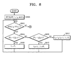
- FIGS. 8-10 are flowcharts for explaining a coordinate calculation method of detecting multi-touch points according to the present invention.
- the t 1 , t 2 , and t 3 values and the TP(p) value are initialized.
- the coordinate values of t 1 , t 2 , and t 3 are all set to (-1, -1) and the TP(p) value is initialized to "0".
- Operation 802 whether the TP(P n ) value of a pixel P n is not less than TP(t 1 ) is determined.
- the TP(P n ) value is not less than (e.g., greater than or equal to) TP(t 1 )
- Operation 804 is performed and whether the distance between P n and t 1 is not greater than (e.g., less than or equal to) d is determined.
- t 1 is updated with P n .
- Operation 802 is performed with respect to the next pixel.
- Operation 804 when the distance between P n and t 1 is not less than d, Operation 808 is performed and whether the distance between P n and t 2 is not greater than d is determined. As a result of the determination in Operation 808, when the distance between P n and t 2 is not greater than (e.g., less than are equal to) d, Operation 810 is performed so that t 2 is updated with t 1 and t 1 is updated with P n . Operation 802 is performed with respect to the next pixel.
- Operation 812 is performed so that t3 is updated with t 2 , t 2 is updated with t 1 , and t 1 is updated with P n .
- Operation 802 is performed with respect to the next pixel.
- Operation 900 is performed and whether TP(P n ) is not less than (e.g., greater than or equal to) TP(t 2 ) is determined.
- Operation 902 is performed and whether the distance between P n and t 1 is not less than (e.g., greater than or equal to) d and the distance between P n and t 2 is not greater than (e.g., less than are equal to) d is determined.
- Operation 904 is performed so that t 2 is updated with P n .
- Operation 802 is performed with respect to the next pixel.
- Operation 908 is performed so that t 3 is updated with t 2 and t 2 is updated with P n .
- Operation 802 is performed with respect to the next pixel.
- Operation 1000 is performed and whether TP(P n ) is not less than (e.g., greater than or equal to) TP(t 3 ) is determined.
- Operation 1002 is performed so that, when both of the distance between P n and t 1 and the distance between P n and t 2 are not less than (e.g., greater than or equal to) d, t 3 is updated with P n . Operation 802 is performed with respect to the next pixel.
- an edge image of a finger image is detected from an input image, a touch point image is generated from the edge image, and a touch coordinate is calculated from the touch point image. Therefore, a simple touch recognition algorithm may be implemented utilizing the characteristic of a finger shape. Also, multiple touch points may be accurately detected.
- the present invention is not limited to the number of 3 and a greater or fewer (e.g., 2 touch points or 4 or more touch points) number of touch points may be determined in the same method described above.
- the invention can also be embodied as computer readable codes on a computer readable recording medium.
- the computer readable recording medium is any data storage device that can store data which can be thereafter read by a computer system. Examples of the computer readable recording medium include read-only memory (ROM), random-access memory (RAM), CD-ROMs, magnetic tapes, floppy disks, optical data storage devices, etc.
- the computer readable recording medium can also be distributed over network coupled computer systems so that the computer readable code is stored and executed in a distributed fashion. Also, functional programs, codes, and code segments for accomplishing the present invention can be easily construed by programmers skilled in the art to which the present invention pertains.
Abstract
Description
- The present invention relates to a method and apparatus for detecting a touch point of an object.
- There are a variety of methods to deliver or obtain information by directly touching an information medium. Touch panel displays are a known useful technology and have been used to deliver or obtain such information. For example, touch screen panels incorporating LCD technology have been developed. The touch screen panel incorporating LCD technology may also be applied not only to the LCD field but also to other suitable display fields. In particular, this technology may be applied to organic light emitting diodes (OLEDs) that are regarded as a next generation display technology.
- In an optical sensor type touch panel display device, an optical sensor is arranged in each pixel so that input of information on a screen utilizing light is possible. In the optical sensor type touch panel display device, for example, a photodiode is used as the optical sensor and a capacitor is connected to the photodiode of each pixel. Data of an image is generated by changing the amount of charges of the capacitor according to a change in the amount of light received by the photodiode, and detecting voltages at the opposite ends of the capacitor. A display device having a function as a touch panel or a digitizer has been suggested as a possible application of the optical sensor type touch panel display device. The touch panel function enables input of information by detecting the shadow of an object, for example, a finger, projected onto a screen. Although the input information is recognized through a variety of image recognition algorithms, such image recognition algorithm are complex, and the large amount of calculations needed to operate such complex image recognition algorithms may impose a heavy burden on hardware.
- The present invention is directed toward a method and apparatus for detecting a touch point by analyzing an image obtained by an optical sensor in a display device having a function of inputting information to a screen utilizing light.
- Another aspect of the present invention is directed toward a method and apparatus for detecting multi-touch points.
- According to an embodiment of the present invention, there is provided a method of detecting a touch point, which includes detecting an edge image of a finger image from an input image, generating a touch point image utilizing the detected edge image, and calculating coordinates of the touch point from the touch point image.
- In the generating of the touch point image utilizing the detected edge image, the touch point image may be generated utilizing a gradient direction and gradient magnitude values obtained from the detected edge image.
- In the generating of the touch point image using the detected edge image, the touch point image may be generated by accumulatively summing up the gradient magnitude values with respect to a position separated by a set distance in the gradient direction of the detected edge image.
- The generating of the touch point image utilizing the detected edge image may include setting a center at a position separated by a set distance in the gradient direction with respect to a position where the edge image is detected, and generating the touch point image by summing up the gradient magnitude values with respect to a set area based on the set center.
- In the calculating of the coordinates of the touch point from the touch point image, the coordinates of a pixel at a maximum value of the summed gradient magnitude values in the touch point image may be determined as the coordinates of the touch point.
- The set distance may be a radius of a finger.
- The set area may be determined according to the size of a tip portion of a finger.
- In the calculating of the coordinates of the touch point from the touch point image, coordinates of at least two touch points may be calculated.
- In the calculating of the coordinates of the touch point from the touch point image, the coordinates of the at least two touch points may be calculated by updating the coordinates of the at least two touch points according to the gradient magnitude values accumulatively summed up in the at least two touch points based on a comparison between the coordinates of the at least two touch points and the set distance.
- The calculating of the coordinates of the touch point from the touch point image may include initializing coordinates of initial touch points and gradient magnitude values associated with the coordinates of the initial touch points, determining whether a gradient magnitude value of a pixel is greater than or equal to the gradient magnitude values associated with the coordinates of the initial touch points, for each of the initial touch points wherein the gradient magnitude value of the pixel is greater than the gradient magnitude value associated with the coordinates of the initial touch points, calculating a distance between the coordinates of the pixel and the initialized coordinates of each of the initial touch points, comparing the calculated distance and the set distance for each of the initial touch points and updating the coordinates of the initial touch points according to a result of the comparison, and determining the updated coordinates of the initial touch points as coordinates of the at least two touch points according to the result of the comparison.
- In the updating of the coordinates of the at least two touch points, whether the calculated distances are less than or equal to the set distance may be determined.
- The set distance may be a radius of a finger.
- The calculating operation and the updating operation may be performed for a plurality of pixels.
- In the detecting of the edge image of the finger image from the input image, the edge image of the finger image may be detected from the input image utilizing a Sobel filter.
- According to another embodiment of the present invention, there is provided a method for detecting a touch point, which include detecting an edge image of an image of a finger contacting a touch panel, setting a center at a position separated by a set distance in a gradient direction of the edge image with respect to a position where the edge image is detected, generating a touch point image by accumulatively summing up gradient values of the edge image with respect to a set area based on the set center, and calculating coordinates of the touch point from the touch point image.
- According to another embodiment of the present invention, there is provided a computer readable recording medium having recorded thereon a program for executing a method for detecting a touch point which includes detecting an edge image of a finger image from an input image, generating a touch point image using the detected edge image, and calculating a coordinate of the touch point from the touch point image.
- According to another aspect of the present invention, there is provided an a touch point detector, wherein the detector includes an edge detector configured to detect an edge image of a finger image from an input image, a touch point image generator configured to generate a touch point image utilizing the detected edge image, and a coordinate calculator configured to calculate coordinates of the touch point from the touch point image.
- The touch point image generator may be configured to generate the touch point image utilizing a gradient direction and gradient magnitude values of the detected edge image.
- The touch point image generator may generate the touch point image by accumulatively summing up the gradient magnitude values with respect to a position separated a predetermined distance in the gradient direction of the detected edge image.
- The touch point image generator may include a center setting unit configured to set a center at a position separated by a set distance in the gradient direction with respect to a position where the edge image is detected, and a gradient summing unit configured to generate the touch point image by summing up the gradient magnitude values with respect to a set area based on the set center.
- The coordinate calculator may determine coordinates of a pixel at a maximum value of the summed gradient magnitude values in the touch point image, as the coordinates of the touch point.
- The coordinate calculator may be configured to calculate coordinates of at least two touch points.
- The coordinate calculator may include an initialization unit configured to initialize coordinates of the initial touch points and gradient magnitude values associated with the coordinates of the initial touch points, a distance calculator configured to calculate a distance between coordinates of a pixel and coordinates of each of the touch points, an update determination unit configured to compare the calculated distance and the set distance for each of the initial touch points and to update the coordinates of the initial touch points according to a result of the comparison, and a coordinate determination unit configured to determine the updated coordinates of the initial touch points as the coordinates of the at least two touch points.
- The update determination unit may determine whether the calculated distance is less than or equal to the set distance.
- The distance calculation unit and the update determination unit may perform the calculation of the distances and the update of the coordinates for a plurality of pixels.
- According to another embodiment of the present invention, there is provided a display device having at least one optical sensor detecting touch by a finger, which includes a sensor signal reader configured to read out a signal detected by the optical sensor, and a touch point detector configured to generate an image of shadow of the finger from the signal detected by the optical sensor, detect an edge image from the generated image, generate a touch point image utilizing the detected edge image, and calculate coordinates of a touch point from the touch point image.
- The touch point detector may detect multiple touch points.
- The above and other features of the invention are set out in the appended claims.
- The accompanying drawings, together with the specification, illustrate embodiments of the present invention, and, together with the description, serve to explain the principles of the present invention.
-
FIG. 1 schematically illustrates a display device having a function of inputting information on a screen utilizing light, according to an embodiment of the present invention. -
FIG. 2 is a schematic block diagram of a display device including a touch point detector according to an embodiment of the present invention. -
FIG. 3 is a schematic block diagram of the touch point detector ofFIG. 2 according to an embodiment of the present invention. -
FIG. 4A is an input image to be input to the edge detector ofFIG. 2 according to an embodiment of the present invention. -
FIG. 4B is an edge image output by the edge detector ofFIG. 2 according to an embodiment of the present invention. -
FIG. 5A is a diagram illustrating the generation of a touch point image utilizing the touch point image generator ofFIG. 2 according to an embodiment of the present invention. -
FIG. 5B is a touch point image generated by the touch point image generator ofFIG. 2 according to an embodiment of the present invention. -
FIG. 6 is a schematic block diagram of the touch point image generator ofFIG. 2 according to an embodiment of the present invention. -
FIG. 7 is a schematic block diagram of a coordinate calculator according to an embodiment of the present invention. -
FIGS. 8-10 are flowcharts for explaining a coordinate calculation method for detecting multi-touch points according to another embodiment of the present invention. - In the following detailed description, only certain embodiments of the present invention are shown and described, by way of illustration. As those skilled in the art would recognize, the invention may be embodied in many different forms and should not be construed as being limited to the embodiments set forth herein.
-
FIG. 1 schematically illustrates adisplay device 100 having a function of inputting information on a screen utilizing light, according to an embodiment of the present invention. Referring toFIG. 1 , thedisplay device 100 includes a plurality ofoptical sensors 110. Thedisplay device 100 may also include a plurality of TFTs and a variety of display elements. For example, thedisplay device 100 may include a plurality of electrodes constituting the TFTs, a plurality of layers such as semiconductor layers and insulation layers, and a plurality of organic light emitting devices. The organic light emitting device includes a pixel electrode, an opposite electrode opposite to the pixel electrode, and an intermediate layer which includes a light emitting layer interposed between the pixel electrode (e.g., an anode electrode) and the opposite electrode (e.g., a cathode electrode). In an embodiment, thedisplay device 100 detects a shadow of a finger F and light reflected by the finger F due to external light illuminating the finger F. Also, although an organic light emitting device is specified above, other flat display devices, for example, LCDs or PDPs, may be used instead. - When an object such as the finger F comes into contact with the
display device 100, theoptical sensor 110 detects an optical signal generated by the finger F due to an external or internal light source. For example, when theoptical sensor 110 detects light that is brighter than a set (or predetermined) value, a signal processing unit outputs a high level signal. When theoptical sensor 110 detects light that is darker than a set (or predetermined) value, the signal processing unit outputs a low level signal. Theoptical sensor 110 may be embodied by a PINtype optical diode. -
FIG. 2 is a schematic block diagram of adisplay device 200 including a touch point detector 230 (e.g., touch point detection apparatus 230) according to an embodiment of the present invention. Referring toFIG. 2 , thedisplay device 200 includes anoptical sensor 210. Thetouch point detector 230 is connected to thedisplay device 200 via a sensingsignal reading unit 220. - The
display device 200 includes a plurality of pixels formed of red (R), green (G), and blue (B) that are arranged, with theoptical sensors 210, at positions where a plurality of signal lines and a plurality of scanning lines cross. Thedisplay device 200 performs a display function to display an image based on an image signal transmitted by an external host. - The sensor
signal reading unit 220 reads the signal detected by theoptical sensor 210 of thedisplay device 200 and outputs the detected signal to thetouch point detector 230. Thetouch point detector 230 detects a touch point by analyzing the signal detected by theoptical sensor 210. Thetouch point detector 230 generates an image of a shadow of a finger from a signal detected by theoptical sensor 210, detects an edge image from the finger shadow image (an input image), generates a touch point image (hereinafter, referred to as the TP image) from the detected edge image, and calculates coordinates of a touch point from the generated TP image. The structure and function of thetouch point detector 230 will be described in more detail later. -
FIG. 3 is a schematic block diagram of thetouch point detector 230 ofFIG. 2 . Referring toFIG. 3 , thetouch point detector 230 includes an edge detector 231 (e.g., edge detection unit 231), a TP image generation unit 232 (e.g., touch point image generator 232), and a coordinate calculator 233 (e.g., coordinate calculation unit 233). Although it is not illustrated, thetouch point detector 230 may further include a signal processing unit including a line memory, a gradation circuit, or a binarization circuit, to generate a finger shadow image from the signal detected by theoptical sensor 210. - The
edge detector 231 detects only an edge component from an input image and outputs an edge image. The edge detection may be performed utilizing any suitable edge detection method, for example, a Laplacian filter, a Roberts filter, a Sobel filter, or a Prewitt filter. An example of detecting the edge component utilizing a Sobel filter is described below in further detail. - First, the convolution of an input image A is performed by applying a Sobel operator as in
Equation 1.
- In
Equation 1, Gx and Gy denote the edge components in the directions x and y, respectively. With respect to the Gx and Gy calculated utilizingEquation 1, the amounts and directions of the edge components are calculated utilizing Equations 2 and 3.

- Also, when the value of G calculated from Equation 2 is smaller than a set (or predetermined) critical value, the value of G is determined to be "0". The edge image may be obtained from the above calculation.
FIG. 4A is an input image to be input to the edge detector ofFIG. 2 .FIG. 4B is an edge image output by the edge detector ofFIG. 2 . Specifically, the edge image output by the edge detector ofFIG. 2 is calculated by applying a Sobel filter. - The
TP image generator 232 generates a TP image by summing gradient magnitude values in a set (or predetermined) area with respect to a position separated a set (or predetermined) distance in a gradient direction Θ of the output edge image. -
FIG. 5A is a diagram illustrating the generation of a touch point image utilizing the touch point image generator ofFIG. 2 .FIG. 5B is a touch point image generated by theTP image generator 232 ofFIG. 2 . Referring toFIG. 5A , a center position is set at a position separated a set (or predetermined) distance in the gradient direction Θ. For example, the set (or predetermined) distance is a distance corresponding to a radius of a finger, from a position where an edge is detected. Since the tip of a finger normally has a circular shape, the center of the tip of a finger generally converges at a point. The gradient magnitude values are accumulatively summed up in a set (or predetermined) area, for example, 5x5 blocks, from the point. Accordingly, the gradient magnitude value is greater at the position around the tip of a finger. Although the above summing is performed in relation to the 5x5 blocks, the present invention is not limited to this size. For example, the size of the summing area may be determined according to the size of the tip of a finger, that is, an area where a finger actually touches the display device.FIG. 5B is a touch point image generated by the touch point image generator ofFIG. 2 , and represents a final TP image. -
FIG. 6 is a schematic block diagram of the touchpoint image generator 232 ofFIG. 2 . Referring toFIG. 6 , theTP image generator 232 includes acenter setting unit 234 and agradient summing unit 235. - The
center setting unit 234 sets a center at a position separated by a set (or predetermined) distance in a set (or predetermined) direction from the position where the edge is detected in theedge detector 231. Thecenter setting unit 234 sets a center at a position separated by a set (or predetermined) distance in a direction from the position where the edge is detected and calculated by Equation 3, that is, in the gradient direction Θ. For example, the set distance is the radial distance of a finger.
As described above, since the tip of a finger normally has a circular shape, the center of the tip of a finger converges at a point. - The
gradient summing unit 235 accumulatively sums up the gradient magnitude values of a set (or predetermined) area with respect to the center set by thecenter setting unit 234. The set area may be set according to the size of the tip of a finger. Accordingly, the gradient magnitude value is greater at the tip of a finger as the size of the finger increases and thus the gradient magnitude value of the tip of a finger may increase as the size of the finger increases. - The coordinate
calculator 233 calculates a coordinate of a touch point utilizing the TP image generated by theTP image generator 232. The coordinatecalculator 233 determines the position of a pixel having the maximum gradient magnitude value in the TP image, as a touch point, and outputs the resulting gradient magnitude value to the host. Referring back toFIG. 5B , in the calculation of coordinates, the position of a pixel that is the brightest in the TP image is determined as a touch point. -
FIG. 7 is a schematic block diagram of the coordinatecalculator 233. In the above-described embodiment, when a single touch point is to be determined, the position of the brightest pixel in the TP image may be determined as a touch point. However, when multiple touches, for example, three touch points, are to be determined, the method of determining a touch point based on the position of the brightest pixel may not be effective. When three touch points are to be found in order of brightness, for example, it is impossible to accurately detect these touch points because the three brightest pixels may be found in one TP image. Thus, a method of detecting a touch point having a local maximum gradient magnitude value in a TP image to implement a multi-touch function is provided according to a further embodiment of the present invention. - In this embodiment, three touch points t1, t2, and t3 are determined for all pixel values P of a TP image. Assume that TP(t1)>TP(t2)> TP(t3), and that TP(p) is a gradient magnitude value accumulated in a pixel p. Thus, TP(t1) is a gradient value accumulated in the touch point (t1). It is assumed that the t1, t2, and t3 values are maintained to be over a set (or predetermined) distance d. The set distance d may be the size of a radius of a finger, for example, 0.5 cm.
- Referring to
FIG. 7 , the coordinate calculator 233 (e.g., coordinate calculation unit 233) includes aninitialization unit 236, a distance calculator 237 (e.g., distance calculation unit 237), anupdate determination unit 238, and a coordinate determinator 239 (e.g., coordinate determination unit 239). Theinitialization unit 236 initializes the initial t1, t2, and t3 values and the TP(p) value. For example, the initial t1, t2, and t3 are all set to (-1, -1) based on a position of a pixel that does not exist. At this time, TP(p) is initialized to "0". - The
distance calculator 237 calculates the distance between the coordinate of a pixel (e.g., a present pixel) and each of t1, t2, and t3. Theupdate determination unit 238 updates the values of t1, t2, and t3 according to whether the distance between the coordinate of the pixel and each of t1, t2, and t3 is not less than or less than a set (or predetermined) distance d. The coordinatedetermination unit 238 determines the final updated coordinate values of t1, t2, and t3 as resulting gradient magnitude values of multiple touch points. -
FIGS. 8-10 are flowcharts for explaining a coordinate calculation method of detecting multi-touch points according to the present invention. Referring toFIG. 8 , in Operation 800, the t1, t2, and t3 values and the TP(p) value are initialized. For example, the coordinate values of t1, t2, and t3 are all set to (-1, -1) and the TP(p) value is initialized to "0". - In Operation 802, whether the TP(Pn) value of a pixel Pn is not less than TP(t1) is determined. When the TP(Pn) value is not less than (e.g., greater than or equal to) TP(t1), Operation 804 is performed and whether the distance between Pn and t1 is not greater than (e.g., less than or equal to) d is determined. As a result of the determination in Operation 804, when the distance between Pn and t1 is not greater than (e.g., less than or equal to) d, t1 is updated with Pn. Operation 802 is performed with respect to the next pixel.
- In Operation 804, when the distance between Pn and t1 is not less than d, Operation 808 is performed and whether the distance between Pn and t2 is not greater than d is determined. As a result of the determination in Operation 808, when the distance between Pn and t2 is not greater than (e.g., less than are equal to) d, Operation 810 is performed so that t2 is updated with t1 and t1 is updated with Pn. Operation 802 is performed with respect to the next pixel.
- As a result of the determination in Operation 808, when the distance between Pn and t2 is not less than (e.g., greater than or equal to) d, Operation 812 is performed so that t3 is updated with t2, t2 is updated with t1, and t1 is updated with Pn. Operation 802 is performed with respect to the next pixel.
- Referring to
FIGS. 8 and9 , as a result of the determination in Operation 802, when TP(Pn) is not greater than (e.g., less than are equal to) TP(t1),Operation 900 is performed and whether TP(Pn) is not less than (e.g., greater than or equal to) TP(t2) is determined. As a result of the determination inOperation 900, when TP(Pn) is not greater than (e.g., less than are equal to) TP(t2), Operation 902 is performed and whether the distance between Pn and t1 is not less than (e.g., greater than or equal to) d and the distance between Pn and t2 is not greater than (e.g., less than are equal to) d is determined. When the distance between Pn and t1 is not less than (e.g., greater than or equal to) d and the distance between Pn and t2 is not greater than (e.g., less than are equal to) d, Operation 904 is performed so that t2 is updated with Pn. Operation 802 is performed with respect to the next pixel. - As a result of the determination in Operation 902, when the distance between Pn and t1 is not less than (e.g., greater than or equal to) d and the distance between Pn and t2 is not less than (e.g., greater than or equal to) d, Operation 908 is performed so that t3 is updated with t2 and t2 is updated with Pn. Operation 802 is performed with respect to the next pixel.
- Referring to
FIGS. 8-10 , as a result of the determination inOperation 900, when TP(Pn) is not greater than (e.g., less than are equal to) TP(t2), Operation 1000 is performed and whether TP(Pn) is not less than (e.g., greater than or equal to) TP(t3) is determined. As a result of the determination in Operation 1000, when TP(Pn) is not less than (e.g., greater than or equal to) TP(t3), Operation 1002 is performed so that, when both of the distance between Pn and t1 and the distance between Pn and t2 are not less than (e.g., greater than or equal to) d, t3 is updated with Pn. Operation 802 is performed with respect to the next pixel. - As described above, in the method of detecting a touch point according to the present invention, an edge image of a finger image is detected from an input image, a touch point image is generated from the edge image, and a touch coordinate is calculated from the touch point image. Therefore, a simple touch recognition algorithm may be implemented utilizing the characteristic of a finger shape. Also, multiple touch points may be accurately detected.
- Although the determination of coordinates of multi-touch points, that is, touch points of three portions is described with reference to
FIGS. 8-10 , the present invention is not limited to the number of 3 and a greater or fewer (e.g., 2 touch points or 4 or more touch points) number of touch points may be determined in the same method described above. - The invention can also be embodied as computer readable codes on a computer readable recording medium. The computer readable recording medium is any data storage device that can store data which can be thereafter read by a computer system. Examples of the computer readable recording medium include read-only memory (ROM), random-access memory (RAM), CD-ROMs, magnetic tapes, floppy disks, optical data storage devices, etc. The computer readable recording medium can also be distributed over network coupled computer systems so that the computer readable code is stored and executed in a distributed fashion. Also, functional programs, codes, and code segments for accomplishing the present invention can be easily construed by programmers skilled in the art to which the present invention pertains.
- While the present invention has been described in connection with certain embodiments, it is to be understood that the invention is not limited to the disclosed embodiments, but, on the contrary, is intended to cover various modifications and equivalent arrangements included within the scope of the appended claims, and equivalents thereof.
Claims (20)
- A method for detecting a touch point, the method comprising:detecting an edge image of a finger image from an input image;generating a touch point image utilizing the detected edge image; andcalculating coordinates of the touch point from the touch point image.
- A method according to claim 1, wherein, in the generating of the touch point image utilizing the detected edge image, the touch point image is generated utilizing a gradient direction and gradient magnitude values obtained from the detected edge image.
- A method according to claim 2, wherein, in the generating of the touch point image utilizing the detected edge image, the touch point image is generated by accumulatively summing up the gradient magnitude values with respect to a position separated by a set distance in the gradient direction of the detected edge image.
- A method according to claim 3, wherein the generating of the touch point image utilizing the detected edge image comprises:setting a center at a position separated by the set distance in the gradient direction with respect to a position where the edge image is detected; andgenerating the touch point image by summing up the gradient magnitude values with respect to a set area based on the set center.
- A method according to claim 4, wherein, in the calculating of the coordinates of the touch point from the touch point image, coordinates of a pixel at a maximum value of the summed gradient magnitude values in the touch point image are determined as the coordinates of the touch point.
- A method according to claim 4 or 5, wherein the set distance is a radius of a finger.
- A method according to claim 4, 5 or 6 wherein the set area is determined according to the size of a tip portion of a finger.
- A method according to claim 4, wherein, in the calculating of the coordinates of the touch point from the touch point image, coordinates of at least two touch points are calculated.
- A method according to claim 8, wherein, in the calculating of the coordinates of the touch point from the touch point image, the coordinates of the at least two touch points are calculated by updating the coordinates of the at least two touch points according to the gradient magnitude values accumulatively summed up in the at least two touch points based on a comparison between the coordinates of the at least two touch points and the set distance.
- A method according to claim 8, wherein the calculating of the coordinates of the at least two touch points from the touch point image comprises:initializing coordinates of initial touch points and gradient magnitude values associated with the coordinates of the initial touch points;determining whether a gradient magnitude value of a pixel is greater than or equal to the gradient magnitude values associated with the coordinates of the initial touch points; andfor each of the initial touch points wherein the gradient magnitude value of the pixel is greater than the gradient magnitude value associated with the coordinates of the initial touch points,calculating a distance between coordinates of the pixel and the initialized coordinates of each of the initial touch points;comparing the calculated distance and the set distance for each of the initial touch points and updating the coordinates of the initial touch points according to a result of the comparison; anddetermining the updated coordinates of the initial touch points as the coordinates of the at least two touch points according to the result of the comparison.
- A method according to claim 10, wherein, in the updating of the coordinates of the at least two touch points, whether the calculated distances are less than or equal to the set distances is determined,
wherein, in the updating of the coordinates of the at least two touch points, the updated coordinates of the initial touch points are determined as the coordinates of the at least two touch points when the calculated distances are less than or equal to the set distance,
wherein the set distances are a radius of a finger. - A computer readable recording medium having recorded thereon a program for executing a method according to any preceding claim.
- A touch point detector, the detector comprising:an edge detector configured to detect an edge image of a finger image from an input image;a touch point image generator configured to generate a touch point image utilizing the detected edge image; anda coordinate calculator configured to calculate coordinates of the touch point from the touch point image.
- A detector according to claim 13, wherein the touch point image generator is configured to generate the touch point image utilizing a gradient direction and gradient magnitude values of the detected edge image,
wherein the touch point image generator is adapted to generate the touch point image by accumulatively summing up the gradient magnitude values with respect to a position separated by a set distance in the gradient direction of the detected edge image. - A detector of claim 14, wherein the touch point image generator comprises:a center setting unit configured to set a center at a position separated by a set distance in the gradient direction with respect to a position where the edge image is detected; anda gradient summing unit configured to generate the touch point image by summing up the gradient magnitude values with respect to a set area based on the set center.
- A detector according to claim 13, 14 or 15, wherein the coordinate calculator determines coordinates of a pixel at a maximum value of the summed gradient magnitude values in the touch point image as the coordinates of the touch point.
- A detector according to claims, wherein the coordinate calculator is configured to calculate coordinates of at least two touch points.
- A detector according to claim 17, wherein the coordinate calculator comprises:an initialization unit configured to initialize coordinates of initial touch points and gradient magnitude values associated with the coordinates of the initial touch points;a distance calculator configured to calculate a distance between coordinates of a pixel and the initialized coordinates of each of the touch points;an update determination unit configured to compare the calculated distance and the set distance for each of the initial touch points and to update the coordinates of the initial touch points according to a result of the comparison; anda coordinate determination unit configured to determine the updated coordinates of the initial touch points as the coordinates of the at least two touch points,wherein the update determination unit determines whether the calculated distance is less than or equal to the set distance.
- A detector according to claim 18, wherein in the update determination unit, the updated coordinates of the initial touch points are determined as the coordinates of the at least two touch points when the calculated distances are less than or equal to the set distance.
- A display device having at least one optical sensor detecting touch by a finger, the display device comprising:a sensor signal reader configured to read out a signal detected by the optical sensor; anda touch point detector, wherein the touch point detector is as set out in one of claims 13 to 19.
Applications Claiming Priority (1)
| Application Number | Priority Date | Filing Date | Title |
|---|---|---|---|
| KR1020080102107A KR100975869B1 (en) | 2008-10-17 | 2008-10-17 | Method and apparatus for detecting touch point |
Publications (2)
| Publication Number | Publication Date |
|---|---|
| EP2182427A2 true EP2182427A2 (en) | 2010-05-05 |
| EP2182427A3 EP2182427A3 (en) | 2011-06-08 |
Family
ID=41863704
Family Applications (1)
| Application Number | Title | Priority Date | Filing Date |
|---|---|---|---|
| EP09252432A Ceased EP2182427A3 (en) | 2008-10-17 | 2009-10-16 | Method and apparatus for detecting touch point |
Country Status (6)
| Country | Link |
|---|---|
| US (1) | US8421775B2 (en) |
| EP (1) | EP2182427A3 (en) |
| JP (1) | JP5213831B2 (en) |
| KR (1) | KR100975869B1 (en) |
| CN (1) | CN101727239B (en) |
| TW (1) | TWI417769B (en) |
Families Citing this family (22)
| Publication number | Priority date | Publication date | Assignee | Title |
|---|---|---|---|---|
| US20090174674A1 (en) * | 2008-01-09 | 2009-07-09 | Qualcomm Incorporated | Apparatus and methods for a touch user interface using an image sensor |
| CN102612677B (en) * | 2009-10-26 | 2015-09-02 | 株式会社半导体能源研究所 | Display device and semiconductor devices |
| KR101666580B1 (en) * | 2009-12-23 | 2016-10-14 | 엘지디스플레이 주식회사 | Touch Detection Method |
| JP5693729B2 (en) * | 2010-09-15 | 2015-04-01 | アドヴァンスト・シリコン・ソシエテ・アノニム | Method for detecting an arbitrary number of touches from a multi-touch device |
| KR101706237B1 (en) * | 2010-11-26 | 2017-02-14 | 엘지디스플레이 주식회사 | Touch screen display device and method for determining touch in the same |
| TWI423093B (en) * | 2010-12-03 | 2014-01-11 | Au Optronics Corp | Method of a touch panel determining multi-touch |
| US9524041B2 (en) * | 2010-12-22 | 2016-12-20 | Intel Corporation | Touch sensor gesture recognition for operation of mobile devices |
| CN102541356A (en) * | 2010-12-24 | 2012-07-04 | 敦南科技股份有限公司 | Touch point positioning method for optical touch panel and optical touch panel device |
| CN102129332A (en) * | 2011-03-07 | 2011-07-20 | 广东威创视讯科技股份有限公司 | Detection method and device of touch points for image recognition |
| CN102622137B (en) * | 2012-02-29 | 2014-12-03 | 广东威创视讯科技股份有限公司 | Touch screen multi-point touch control method and device for front positioning of cameras |
| JP6049334B2 (en) * | 2012-07-12 | 2016-12-21 | キヤノン株式会社 | Detection apparatus, detection method, and program |
| KR101960381B1 (en) * | 2012-09-06 | 2019-03-20 | 엘지디스플레이 주식회사 | Touch sensing method and apparatus reflecting user's intention |
| CN103279235B (en) * | 2013-05-28 | 2016-08-10 | 广州视睿电子科技有限公司 | The method and system of location, touch point |
| CN103279234B (en) * | 2013-05-28 | 2016-12-28 | 广州视睿电子科技有限公司 | The method and system of location, touch point |
| KR102112675B1 (en) * | 2013-09-23 | 2020-05-19 | 엘지디스플레이 주식회사 | Touch sensing system and driving method thereof |
| TWI696103B (en) | 2013-11-29 | 2020-06-11 | 日商半導體能源研究所股份有限公司 | Data processing device and driving method thereof |
| KR102205906B1 (en) * | 2013-12-09 | 2021-01-22 | 삼성전자주식회사 | Method and system for modifying contour of object in image |
| CN106557202A (en) * | 2016-10-28 | 2017-04-05 | 深圳埃蒙克斯科技有限公司 | The detection method and system of touch point |
| CN107299321B (en) * | 2017-07-28 | 2019-07-26 | 武汉华星光电半导体显示技术有限公司 | Evaporation source and evaporator |
| CN108109581B (en) * | 2018-01-16 | 2018-12-25 | 深圳鑫亿光科技有限公司 | Interactive LED display and its display methods |
| CN108762557A (en) * | 2018-05-22 | 2018-11-06 | 北京集创北方科技股份有限公司 | A kind of touch detecting method and computer readable storage medium |
| KR20220169059A (en) | 2021-06-17 | 2022-12-27 | 삼성디스플레이 주식회사 | Display device and operating method thereof |
Citations (3)
| Publication number | Priority date | Publication date | Assignee | Title |
|---|---|---|---|---|
| US20060170658A1 (en) | 2005-02-03 | 2006-08-03 | Toshiba Matsushita Display Technology Co., Ltd. | Display device including function to input information from screen by light |
| US20070070007A1 (en) | 2005-09-29 | 2007-03-29 | Toshiba Matsushita Display Technology Co., Ltd. | Liquid crystal display apparatus |
| US20080226192A1 (en) * | 2007-03-14 | 2008-09-18 | Micron Technology, Inc. | Image feature identification and motion compensation apparatus, systems, and methods |
Family Cites Families (13)
| Publication number | Priority date | Publication date | Assignee | Title |
|---|---|---|---|---|
| US9513744B2 (en) * | 1994-08-15 | 2016-12-06 | Apple Inc. | Control systems employing novel physical controls and touch screens |
| JPH0969037A (en) * | 1995-08-31 | 1997-03-11 | Sharp Corp | Data processor |
| US7254775B2 (en) * | 2001-10-03 | 2007-08-07 | 3M Innovative Properties Company | Touch panel system and method for distinguishing multiple touch inputs |
| TWI253584B (en) * | 2004-11-23 | 2006-04-21 | Ind Tech Res Inst | Coordinate positioning system of touch panel |
| CN100407120C (en) * | 2005-02-03 | 2008-07-30 | 东芝松下显示技术有限公司 | Display device including function to input information from screen by light |
| JP2007001233A (en) * | 2005-06-27 | 2007-01-11 | Konica Minolta Business Technologies Inc | Electric appliance, and program |
| JP2007011233A (en) * | 2005-07-04 | 2007-01-18 | Toshiba Matsushita Display Technology Co Ltd | Flat display device and imaging method using same |
| JP2007183706A (en) * | 2006-01-04 | 2007-07-19 | Epson Imaging Devices Corp | Touch sensor system |
| KR101281830B1 (en) * | 2006-09-26 | 2013-07-03 | 엘지디스플레이 주식회사 | Liquid crystal display having multi-touch sensing function and driving method thereof |
| JP2008250774A (en) * | 2007-03-30 | 2008-10-16 | Denso Corp | Information equipment operation device |
| JP4727615B2 (en) | 2007-03-30 | 2011-07-20 | シャープ株式会社 | Image processing apparatus, control program, computer-readable recording medium, electronic apparatus, and control method for image processing apparatus |
| US8115753B2 (en) * | 2007-04-11 | 2012-02-14 | Next Holdings Limited | Touch screen system with hover and click input methods |
| CN101689244B (en) * | 2007-05-04 | 2015-07-22 | 高通股份有限公司 | Camera-based user input for compact devices |
-
2008
- 2008-10-17 KR KR1020080102107A patent/KR100975869B1/en active IP Right Grant
-
2009
- 2009-09-24 US US12/566,512 patent/US8421775B2/en active Active
- 2009-10-14 TW TW098134731A patent/TWI417769B/en active
- 2009-10-16 EP EP09252432A patent/EP2182427A3/en not_active Ceased
- 2009-10-16 CN CN200910205672.5A patent/CN101727239B/en active Active
- 2009-10-16 JP JP2009239518A patent/JP5213831B2/en active Active
Patent Citations (3)
| Publication number | Priority date | Publication date | Assignee | Title |
|---|---|---|---|---|
| US20060170658A1 (en) | 2005-02-03 | 2006-08-03 | Toshiba Matsushita Display Technology Co., Ltd. | Display device including function to input information from screen by light |
| US20070070007A1 (en) | 2005-09-29 | 2007-03-29 | Toshiba Matsushita Display Technology Co., Ltd. | Liquid crystal display apparatus |
| US20080226192A1 (en) * | 2007-03-14 | 2008-09-18 | Micron Technology, Inc. | Image feature identification and motion compensation apparatus, systems, and methods |
Also Published As
| Publication number | Publication date |
|---|---|
| KR20100042900A (en) | 2010-04-27 |
| TWI417769B (en) | 2013-12-01 |
| US20100097349A1 (en) | 2010-04-22 |
| US8421775B2 (en) | 2013-04-16 |
| CN101727239A (en) | 2010-06-09 |
| TW201019188A (en) | 2010-05-16 |
| CN101727239B (en) | 2016-04-13 |
| JP5213831B2 (en) | 2013-06-19 |
| EP2182427A3 (en) | 2011-06-08 |
| JP2010097616A (en) | 2010-04-30 |
| KR100975869B1 (en) | 2010-08-13 |
Similar Documents
| Publication | Publication Date | Title |
|---|---|---|
| US8421775B2 (en) | Method and apparatus for detecting touch point | |
| US10168843B2 (en) | System and method for determining user input from occluded objects | |
| JP5274507B2 (en) | Touch motion recognition method and apparatus | |
| US9870096B2 (en) | Systems and methods for reducing effects of interference in input devices | |
| US8600107B2 (en) | Interactive input system and method | |
| CN107219272B (en) | Moisture management | |
| EP2353069B1 (en) | Stereo optical sensors for resolving multi-touch in a touch detection system | |
| US8436262B2 (en) | Detecting method for touch panel | |
| US8576200B2 (en) | Multiple-input touch panel and method for gesture recognition | |
| TWI725187B (en) | Normalizing capacitive sensing measurements to reduce effects of low ground mass and noise | |
| CN108475137B (en) | Common mode display noise mitigation using hybrid estimation methods | |
| US20220164060A1 (en) | Touch panel system, display device, and method for controlling touch panel system | |
| US10203806B2 (en) | Low ground mass artifact management | |
| US20200218425A1 (en) | Touch positioning method and apparatus, and electronic device | |
| CN110309794B (en) | Biological feature acquisition method, feature acquisition device, and computer-readable storage medium | |
| CN115268695A (en) | Touch screen detection device, method, chip, display device and electronic device |
Legal Events
| Date | Code | Title | Description |
|---|---|---|---|
| PUAI | Public reference made under article 153(3) epc to a published international application that has entered the european phase |
Free format text: ORIGINAL CODE: 0009012 |
|
| 17P | Request for examination filed |
Effective date: 20091029 |
|
| AK | Designated contracting states |
Kind code of ref document: A2 Designated state(s): AT BE BG CH CY CZ DE DK EE ES FI FR GB GR HR HU IE IS IT LI LT LU LV MC MK MT NL NO PL PT RO SE SI SK SM TR |
|
| AX | Request for extension of the european patent |
Extension state: AL BA RS |
|
| PUAL | Search report despatched |
Free format text: ORIGINAL CODE: 0009013 |
|
| AK | Designated contracting states |
Kind code of ref document: A3 Designated state(s): AT BE BG CH CY CZ DE DK EE ES FI FR GB GR HR HU IE IS IT LI LT LU LV MC MK MT NL NO PL PT RO SE SI SK SM TR |
|
| AX | Request for extension of the european patent |
Extension state: AL BA RS |
|
| 17Q | First examination report despatched |
Effective date: 20120412 |
|
| RAP1 | Party data changed (applicant data changed or rights of an application transferred) |
Owner name: SAMSUNG DISPLAY CO., LTD. |
|
| RAP1 | Party data changed (applicant data changed or rights of an application transferred) |
Owner name: SAMSUNG DISPLAY CO., LTD. |
|
| STAA | Information on the status of an ep patent application or granted ep patent |
Free format text: STATUS: THE APPLICATION HAS BEEN REFUSED |
|
| 18R | Application refused |
Effective date: 20180131 |