EP2187190A2 - System and method for detecting and measuring vibration in an industrial roll - Google Patents
System and method for detecting and measuring vibration in an industrial roll Download PDFInfo
- Publication number
- EP2187190A2 EP2187190A2 EP09175910A EP09175910A EP2187190A2 EP 2187190 A2 EP2187190 A2 EP 2187190A2 EP 09175910 A EP09175910 A EP 09175910A EP 09175910 A EP09175910 A EP 09175910A EP 2187190 A2 EP2187190 A2 EP 2187190A2
- Authority
- EP
- European Patent Office
- Prior art keywords
- roll
- nip
- sensor units
- condition
- sensors
- Prior art date
- Legal status (The legal status is an assumption and is not a legal conclusion. Google has not performed a legal analysis and makes no representation as to the accuracy of the status listed.)
- Granted
Links
- 238000000034 method Methods 0.000 title claims description 18
- 230000013011 mating Effects 0.000 claims abstract description 14
- 239000000463 material Substances 0.000 claims description 13
- 238000005259 measurement Methods 0.000 claims description 13
- 238000006073 displacement reaction Methods 0.000 claims description 5
- 229920002681 hypalon Polymers 0.000 claims description 5
- 239000002174 Styrene-butadiene Substances 0.000 claims description 4
- 229920003048 styrene butadiene rubber Polymers 0.000 claims description 4
- 239000004593 Epoxy Substances 0.000 claims description 3
- 244000043261 Hevea brasiliensis Species 0.000 claims description 3
- 229920000459 Nitrile rubber Polymers 0.000 claims description 3
- MTAZNLWOLGHBHU-UHFFFAOYSA-N butadiene-styrene rubber Chemical compound C=CC=C.C=CC1=CC=CC=C1 MTAZNLWOLGHBHU-UHFFFAOYSA-N 0.000 claims description 3
- 229920003052 natural elastomer Polymers 0.000 claims description 3
- 229920001194 natural rubber Polymers 0.000 claims description 3
- 229920001084 poly(chloroprene) Polymers 0.000 claims description 3
- 229920002635 polyurethane Polymers 0.000 claims description 3
- 239000004814 polyurethane Substances 0.000 claims description 3
- 239000011115 styrene butadiene Substances 0.000 claims description 3
- -1 EDPM Substances 0.000 claims 2
- 239000010410 layer Substances 0.000 description 19
- 238000004891 communication Methods 0.000 description 8
- 230000003750 conditioning effect Effects 0.000 description 4
- 230000000694 effects Effects 0.000 description 4
- 239000000835 fiber Substances 0.000 description 4
- 230000001939 inductive effect Effects 0.000 description 4
- 239000013307 optical fiber Substances 0.000 description 3
- 238000013459 approach Methods 0.000 description 2
- 230000008859 change Effects 0.000 description 2
- 238000010276 construction Methods 0.000 description 2
- 238000013016 damping Methods 0.000 description 2
- 230000007423 decrease Effects 0.000 description 2
- 238000004519 manufacturing process Methods 0.000 description 2
- 238000012986 modification Methods 0.000 description 2
- 230000004048 modification Effects 0.000 description 2
- 238000012545 processing Methods 0.000 description 2
- 229910001018 Cast iron Inorganic materials 0.000 description 1
- 229920002943 EPDM rubber Polymers 0.000 description 1
- 239000002033 PVDF binder Substances 0.000 description 1
- 229910000831 Steel Inorganic materials 0.000 description 1
- 239000000654 additive Substances 0.000 description 1
- 239000012790 adhesive layer Substances 0.000 description 1
- 238000005452 bending Methods 0.000 description 1
- 238000009530 blood pressure measurement Methods 0.000 description 1
- 239000003990 capacitor Substances 0.000 description 1
- 239000000919 ceramic Substances 0.000 description 1
- 238000006243 chemical reaction Methods 0.000 description 1
- 238000000576 coating method Methods 0.000 description 1
- 239000002131 composite material Substances 0.000 description 1
- 230000001276 controlling effect Effects 0.000 description 1
- 230000002596 correlated effect Effects 0.000 description 1
- 230000007797 corrosion Effects 0.000 description 1
- 238000005260 corrosion Methods 0.000 description 1
- 230000008878 coupling Effects 0.000 description 1
- 238000010168 coupling process Methods 0.000 description 1
- 238000005859 coupling reaction Methods 0.000 description 1
- 230000002950 deficient Effects 0.000 description 1
- 238000013461 design Methods 0.000 description 1
- 238000001514 detection method Methods 0.000 description 1
- 238000010586 diagram Methods 0.000 description 1
- 239000013536 elastomeric material Substances 0.000 description 1
- 238000005516 engineering process Methods 0.000 description 1
- HQQADJVZYDDRJT-UHFFFAOYSA-N ethene;prop-1-ene Chemical group C=C.CC=C HQQADJVZYDDRJT-UHFFFAOYSA-N 0.000 description 1
- 239000000945 filler Substances 0.000 description 1
- 238000000691 measurement method Methods 0.000 description 1
- 239000002184 metal Substances 0.000 description 1
- 229910052751 metal Inorganic materials 0.000 description 1
- 239000007769 metal material Substances 0.000 description 1
- 238000012544 monitoring process Methods 0.000 description 1
- 230000003287 optical effect Effects 0.000 description 1
- 239000006187 pill Substances 0.000 description 1
- 229920002981 polyvinylidene fluoride Polymers 0.000 description 1
- 230000002028 premature Effects 0.000 description 1
- 230000003014 reinforcing effect Effects 0.000 description 1
- 238000012827 research and development Methods 0.000 description 1
- 239000007787 solid Substances 0.000 description 1
- 239000010959 steel Substances 0.000 description 1
- 229920003051 synthetic elastomer Polymers 0.000 description 1
- 239000005061 synthetic rubber Substances 0.000 description 1
- 229920001897 terpolymer Polymers 0.000 description 1
- 230000005641 tunneling Effects 0.000 description 1
Images


Classifications
-
- G—PHYSICS
- G01—MEASURING; TESTING
- G01L—MEASURING FORCE, STRESS, TORQUE, WORK, MECHANICAL POWER, MECHANICAL EFFICIENCY, OR FLUID PRESSURE
- G01L5/00—Apparatus for, or methods of, measuring force, work, mechanical power, or torque, specially adapted for specific purposes
- G01L5/0061—Force sensors associated with industrial machines or actuators
- G01L5/0076—Force sensors associated with manufacturing machines
- G01L5/0085—Force sensors adapted for insertion between cooperating machine elements, e.g. for measuring the nip force between rollers
-
- G—PHYSICS
- G01—MEASURING; TESTING
- G01L—MEASURING FORCE, STRESS, TORQUE, WORK, MECHANICAL POWER, MECHANICAL EFFICIENCY, OR FLUID PRESSURE
- G01L5/00—Apparatus for, or methods of, measuring force, work, mechanical power, or torque, specially adapted for specific purposes
- G01L5/04—Apparatus for, or methods of, measuring force, work, mechanical power, or torque, specially adapted for specific purposes for measuring tension in flexible members, e.g. ropes, cables, wires, threads, belts or bands
- G01L5/045—Apparatus for, or methods of, measuring force, work, mechanical power, or torque, specially adapted for specific purposes for measuring tension in flexible members, e.g. ropes, cables, wires, threads, belts or bands for measuring the tension across the width of a band-shaped flexible member
-
- G—PHYSICS
- G01—MEASURING; TESTING
- G01N—INVESTIGATING OR ANALYSING MATERIALS BY DETERMINING THEIR CHEMICAL OR PHYSICAL PROPERTIES
- G01N29/00—Investigating or analysing materials by the use of ultrasonic, sonic or infrasonic waves; Visualisation of the interior of objects by transmitting ultrasonic or sonic waves through the object
- G01N29/14—Investigating or analysing materials by the use of ultrasonic, sonic or infrasonic waves; Visualisation of the interior of objects by transmitting ultrasonic or sonic waves through the object using acoustic emission techniques
-
- G—PHYSICS
- G01—MEASURING; TESTING
- G01N—INVESTIGATING OR ANALYSING MATERIALS BY DETERMINING THEIR CHEMICAL OR PHYSICAL PROPERTIES
- G01N2291/00—Indexing codes associated with group G01N29/00
- G01N2291/26—Scanned objects
- G01N2291/269—Various geometry objects
- G01N2291/2693—Rotor or turbine parts
Definitions
- the present invention relates generally to industrial rolls, and more particularly to industrial rolls with vibration measurement capability.
- Vibrations are commonly experienced in rotating machine components. In many cases, these vibrations can lead to product irregularities during manufacture, premature wear and failure of machine components, and unbearable environments.
- the components are often sized so that their natural frequencies are well above the frequencies expected from vibration sources. To further reduce or prevent significant vibrations, balancing of individual components is often performed. Quite often, these preventative measures are insufficient at reducing the vibration levels to tolerable levels. Other techniques must be applied after the fact. In some corrective measures, damping is added to the components. With rotating machinery, the operational speeds are often adjusted to reduce certain frequencies of vibrations. In many cases, such measures are insufficient at controlling vibration, so more active techniques are required.
- Paper machine rolls have specific challenges with vibrations. The rolls turn at certain rotational speeds, which will produce a level of vibration at the same frequency for any level of imbalance. Nipped rolls have additional challenges as follows:
- vibration sensors usually involve placing vibration sensors at the bearing mounts and near the ends of the rolls. These sensors can pick up the major effects of the vibrations, but can not always pinpoint the source. It may be desirable to provide a vibration detection system that can generate more and better information about the vibrations of the roll.
- embodiments of the present invention are directed to a system for determining the source of vibration of a nipped roll assembly.
- the system comprises: a first substantially cylindrical roll; a mating structure positioned relative to the first roll to form a nip therewith; a plurality of annular nip condition sensor units mounted on the first roll; each of the annular nip condition sensor units being positioned at different axial locations along the first roll and configured to provide nip condition signals from the nip, the signals indicating a nip condition at multiple circumferential locations; and a processor associated with the sensor units that receives signals from the sensor units.
- the processor is configured to convert the signals from the sensor units into nip condition readings for the multiple circumferential locations at each axial location.
- the nip condition sensor units are pressure sensors. Such a system can detect irregularities in a roll or the mating structure that can cause undesired vibration.
- embodiments of the present invention are directed to a method of assessing vibration in an industrial roll, comprising the steps of: providing a roll that includes a plurality of annular nip condition sensor units mounted thereon, each of the annular nip condition sensor units being positioned at different axial locations along the roll and configured to provide nip condition signals from a nip formed by the roll and a mating structure, rotating the roll; measuring a nip condition at multiple circumferential locations on each sensor unit; and determining the source of vibration in the roll based on the nip condition measurements.
- Figure 1 is a schematic front view of a roll with a vibration detecting system according to embodiments of the present invention.
- Figure 2 is a perspective view of the roll of Figure 1 with part of the cover removed to show the sensors of the vibration detecting system.
- Figure 3 is a section view of the roll of Figure 1 taken along lines 3-3 thereof.
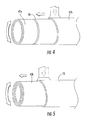
- Figure 4 is a perspective view of the outer base layer being applied over the inner base layer and sensors of the roll of Figure 1 .
- Figure 5 is a perspective view of the topstock layer being applied over the outer base layer of Figure 4 .
- Figure 6 is a schematic diagram of the electronics unit of the roll of Figure 1 .
- Figure 7 is a graph plotting nip pressure as a function of nip angle to demonstrate how a roll surface bump that causes vibration can be detected.
- Figure 8 is a graph plotting nip pressure as a function of nip angle to demonstrate how a non-concentric roll cover that causes vibration can be detected.
- Figure 9 is a schematic perspective view of a roll with a vibration detecting system according to additional embodiments of the present invention.
- a roll designated broadly at 20, is shown in Figures 1-3 .
- the roll 20 is typically positioned adjacent to a mating structure; such as a mating roll or shoe of a shoe press, to form a nip through which a web can pass.
- the roll 20 includes a hollow cylindrical shell or core 22 (see Figure 3 ) and a cover 24 (typically formed of one or more polymeric materials) that encircles the core 22 .
- the core 22 is typically formed of a corrosion-resistant metallic material, such as steel or cast iron.
- the core 22 can be solid or hollow, and if hollow may include devices that can vary pressure or roll profile.
- the cover 24 can take any form and can be formed of any polymeric and/or elastomeric material recognized by those skilled in this art to be suitable for use with a roll.
- Exemplary materials include natural rubber, synthetic rubbers such as neoprene, styrene-butadiene (SBR), nitrile rubber, chlorosulfonated polyethylene (“CSPE” - also known under the trade name HYPALON), EDPM (the name given to an ethylene-propylene terpolymer formed of ethylene-propylene diene monomer), epoxy, and polyurethane.
- SBR styrene-butadiene
- CSPE chlorosulfonated polyethylene
- EDPM the name given to an ethylene-propylene terpolymer formed of ethylene-propylene diene monomer
- epoxy and polyurethane.
- the cover 24 may also include reinforcing and filler materials, additives, and the like. Exemplary additional materials are discussed
- the cover 24 will comprise multiple layers.
- Figures 4 and 5 illustrate the application of an inner base layer 42a, an outer base layer 42b and a topstock layer 70; Figure 3 shows these layers in cross-section. Additional layers, such as a "tie-in" layer between the outer base and topstock layers 42b, 70 and an adhesive layer between the shell 22 and the inner base layer 42a, may also be included.
- Construction of the cover 24 may be carried out in any manner known to those skilled in this art to be suitable for the application of a roll cover. Exemplary methods are discussed in U.S. Patent Publication No. 2005/0261115 , the disclosure of which is hereby incorporated herein in its entirety.
- a vibration sensing system 26 for sensing vibration in the roll 20 includes a plurality of nip condition sensors 30, each of which is embedded in the cover 24.
- a sensor being “embedded” in the cover means that the sensor is entirely contained within the cover, and a sensor being “embedded” in a particular layer or set of layers of the cover means that the sensor is entirely contained within that layer or set of layers.
- the vibration sensing system 26 also includes a processor 32 and, in the illustrated embodiment, the sensors 30 are connected via electrical leads (not shown) to an electronics unit 31 that is mounted to one end of the roll 20.
- the electronics unit 31 is included to convert signals produced by the sensors 30 into easily-processed data; in some embodiments, each of the sensors 30 includes a transceiver that can transmit the signals wirelessly to the electronics unit 31 or to a remote receiver for processing ( see, e.g., U.S. Patent No. 7,392,715 ). The electronics unit 31 transmits the signals (typically wirelessly) to the processor 32 for subsequent processing and display.
- the system 26 includes seven nip condition sensors 30 spaced generally equidistant from each other along the length of the roll 20, although typically more sensors 30 would be included at different axial locations to provide additional data.
- Each sensor 30 is annular and substantially encircles the roll 20 at one axial location.
- the pressure profile can be measured completely around the circumference of the roll 20.
- each continuous sensor 30 may be replaced by an annular ring of discrete, relatively closely spaced sensors 30'.
- the sensors 30 measure a nip condition (typically pressure) either directly or indirectly. Any sensor that can measure pressure or another nip condition may be used. For example, the sensor 30 may directly measure pressure, displacement, proximity, strain, electrical charge, voltage, resistance, attenuation, capacitance or inductance, and this measurement can be correlated to nip pressure and/or nip width.
- Typical sensors include piezoelectric sensors, piezoceramic sensors, force sensitive resistor (FSR) sensors, resistive sensors, quantum tunneling composite (QTC) sensors, piezoresistive sensors, capacitive sensors, inductive sensors, optical fibers sensors, and EMFi film sensors. These sensor types are discussed below.
- Piezoelectric sensors produce a charge or a voltage that is proportional to dynamic pressure.
- Suitable piezoelectric sensors can be obtained in the form of a cable from Measurement Specialties, Inc. (Valley Forge, Pennsylvania). KynarTM PVDF film may be used as a piezoelectric sensor and may also be obtained from Measurement Specialties, Inc.
- Piezoceramic materials may be used at higher temperatures than the PDVF films.
- Material PSI-5A4E has a 350°C Curie temperature. In many embodiments, these sensors would be arranged in a discrete array, as shown in Figure 9 . Exemplary sensors are available from Piezo Systems, Inc. Cambridge, Massachusetts.
- FSR sensors have a resistance that is nearly inversely proportional to pressure.
- FSR sensors may be obtained from Interlink Electronics, Inc. (Camarillo, California) or from Tekscan, Inc. (South Boston, Massachusetts)..
- Resistive sensors include all sensors whose resistance is affected by the nip conditions.
- Very short strain gages may be oriented radially and would measure radial strain, which is closely related to radial pressure. Strain gages may be used to measure the circumferential strains in the nip. The axial strain may be near-zero away from the ends of the rolls, but could be non-zero if packaged to decouple the nearly plane strain conditions. These strains are related to pressure level, so strain gages are generally considered an indirect measurement method. Suitable strain gages may be obtained from Vishay Measurements Group ( www.vishaymg.com ). A QTC material is one for which resistance decreases as pressure is increased. QTC pills may be obtained from Peratech Ltd., Durham, United Kingdom.
- Piezoresistive sensors also exhibit a coupling between resistance and applied stress or strain. These sensors could be oriented radially to measure radial pressure.
- An exemplary piezoresistive sensor is HSPPAR, available from Alps Electric Co., Ltd., Campbell, California.
- Capacitive sensors measure pressure by measuring the change in capacitance between two plates or two objects. Capacitive pressure sensors can be obtained from Loadstar Sensors Inc., Sunnyvale, California.
- Inductive sensors are commonly used for displacement measurements, which would be considered an indirect measurement.
- An exemplary inductive sensor is the 2402 sensor, available from Micro-Epsilon, Raleigh, NC.
- Optical fiber sensors have a number of available configurations.
- a microbend fiber may be wrapped around the circumference of the roll. This sensor is sensitive to radial strain. The change in strength/intensity of the light indicates the pressure or strain applied to the sensor.
- An exemplary device is shown in U.S. Patent 6,429,421 .
- An EFPI (extrinsic Fabry-Perot interferometric) sensor is a point sensor and acts as a highly sensitive displacement gauge. Several discrete EFPI sensors would be used in this case.
- Fiber Bragg grating sensors have a grating etched inside the fiber that acts to shift the wavelength of the light that passes through the sensor. In a typical application within a roll cover, the shift would indicate the level of circumferential strain in the cover material.
- Multi-mode and elliptical core (e-core) fibers will experience frequency shifts and intensity changes as the fiber is compressed.
- EMFi films respond to pressure like an active capacitor. They may be suitable for low temperature and low pressure applications. Sensor material may be obtained from Emfit Ltd, Vaajakoski, Finland.
- Temperature compensation may improve the accuracy of the sensor readings. Temperature compensation can be built into some of the sensor types. Separate temperature measuring sensors would be used for other sensors. Common temperature sensors include thermocouples, RTDs, and thermistors. Exemplary temperature compensation techniques are discussed in U.S. Patent Publication No. 2005/0278135 , the disclosure of which is hereby incorporated herein in its entirety.
- the sensors are annular and may be configured as either substantially continuous (as with sensors 30 ) or discrete (as with sensors 30' ).
- a substantially continuous ring may have a gap between the start and stop positions in that it spans only a large part of the circumference, 355 degrees, for example. Such a gap can be used to help locate the position of a reading with the angular position. Alternately, a separate encoder or trigger can be used to keep the readings in sync with absolute position. For pure vibrations measurements, no synchronization may be needed.
- a gap also can help piezoelectric sensors remove the DC component of the signal.
- the discrete sensors 30' shown in Figure 9 may be used where it is convenient in terms of sensor availability or fabrication.
- ceramic piezoelectric sensors may not be readily available in pre-made rings, so a sequence of sensors 30' may be used instead.
- the sensors 30' may be connected in parallel.
- sensors 30, 30' are illustrated as being located beneath the surface of the roll 20 embedded in the base layer 42, in other embodiments sensors may be located at the roll outside surface or beneath the surface at other depths, such as on top of the metal core, over the base, or over intermediate layers.
- the electronics unit 31 may include a signal conditioning module 52.
- Different sensors require different signal conditioning systems.
- resistance sensors often have Wheatstone bridge circuitry.
- Other resistance-based circuits use a precision voltage or current source and measure the voltage over a known resistance element.
- Piezoelectric sensors typically use charge amplifiers.
- Capacitive sensors measure resonant frequencies or use a capacitance to voltage converter.
- Optical fiber sensors measure optical signal strength or frequency shifts.
- the signal conditioning module 52 converts the sensor output to a form that can be read by a data acquisition system 54 (below) or data logging system.
- the electronics unit 31 may also include a data acquisition module 54.
- the data acquisition module 54 converts the sensor signal into a digital measurement. In many cases, the system uses an analog voltage to digital number (A/D) converter.
- A/D analog voltage to digital number
- a controller 56 drives the sensors 30, the signal conditioning and data acquisition modules 52, 54 and any other electronics, and communicates wirelessly with the processor 32.
- the embedded controller 56 may shut down sections of the system at times to conserve power.
- the embedded controller 56 may also multiplex among the many available sensors 30.
- the sensor measurements are communicated by the electronics unit 31 to the processor 32 at a location remote from the roll 20.
- the processor 32 converts the pressure signals into pressure readings for the multiple circumferential locations for each axially-located sensor. In many cases, this off-roll site is in an operator control room.
- the signal is typically transferred using RF communication.
- An exemplary RF transceiver is available from RF Monolithics, Inc., Dallas, Texas.
- the roll communication could be one-way in that signals are transmitted from the roll 20, but no communication is transmitted to the roll 20.
- the roll-based system would have a transmitter, and the off-roll site would use a receiver.
- IR communication and slip rings may also be used to communicate to and from the roll 20. Except for the mesh configuration discussed below, most of the electronics would be mounted on the head of the roll.
- Another embodiment for communication is a wireless mesh configuration, where each sensor has a transceiver near its site, and the many sensors form a mesh configuration for communication.
- This approach is robust in that one weak site may reach a nearby site and have its information transmitted by a stronger wireless site. The robustness is also demonstrated when one site fails and the mesh reconfigures automatically to maintain the communication among the remaining sites.
- Wireless mesh products are available from Crossbow Technology, Inc. San Jose, California.
- one roll of a nipped pair has a flat spot or bump at its surface.
- the pressure profile would be fairly level until the region near the bump passes through the nip, as shown in Figure 7 .
- the offending bump/flat spot can be identified and corrected.
- a cover may be eccentric to its rotational axis.
- the outside diameter could be out of round, or the cover thickness could vary.
- a gently varying pressure profile would be seen for such a case, as is illustrated in Figure 8 .
- the ratio of the rolls dictates the angular period if the mating roll is instrumented with sensors, rather than the eccentric roll.
- the regions with a thicker cover layer would act softer and have lower nip pressures than the thinner regions.
- the structure of the roll 20 may be adjusted (by grinding or the like) based on the pressure measurements to reduce vibration.
- the above examples demonstrate that the machine-direction nip pressure is measured along with vibrations. Accelerometers output vibrations levels as a function of frequency and cannot distinguish between the two cases shown in Figures 7 and 8 .
- the proposed sensing system can provide more pinpoint accuracy for the source of the problems.
- the system may also measure the magnitude of the direct effect of the vibrations on the paper product. That is, whereas an accelerometer can detect that significant vibrations are present, the proposed measurement system produces a measure of the direct effect of these vibrations on the nip pressure seen by the sheet. This direct approach can measure operational problems before the covers are worn or before damage or excessive vibrations develop.
Abstract
Description
- This application claims priority from
U.S. Provisional Patent Application No. 61/114,604, filed November 14, 2008 - The present invention relates generally to industrial rolls, and more particularly to industrial rolls with vibration measurement capability.
- Vibrations are commonly experienced in rotating machine components. In many cases, these vibrations can lead to product irregularities during manufacture, premature wear and failure of machine components, and unbearable environments. At the design level, the components are often sized so that their natural frequencies are well above the frequencies expected from vibration sources. To further reduce or prevent significant vibrations, balancing of individual components is often performed. Quite often, these preventative measures are insufficient at reducing the vibration levels to tolerable levels. Other techniques must be applied after the fact. In some corrective measures, damping is added to the components. With rotating machinery, the operational speeds are often adjusted to reduce certain frequencies of vibrations. In many cases, such measures are insufficient at controlling vibration, so more active techniques are required.
- Paper machine rolls have specific challenges with vibrations. The rolls turn at certain rotational speeds, which will produce a level of vibration at the same frequency for any level of imbalance. Nipped rolls have additional challenges as follows:
- 1) Vibrations may occur at frequencies related to common multiples of roll diameters or felt length. For example, if one roll were three-fifths the diameter of its mating roll, there could be 15 locations on the larger roll where the same dot of the smaller roll touches. The larger roll could then vibrate at frequencies 15 times that of its rotational frequency. Felt seams of press felts often employed in paper machines have been blamed for inducing these types of vibrations and wear. This effect is sometimes called barring.
- 2) Other sources of wear can increase the levels of vibrations. If the nip is considered as a stiff spring, and the roll bodies as masses, this spring-mass system will typically vibrate at its natural frequency. If a roll vibrates at a frequency that is 15 times greater than its rotational frequency, fifteen worn or barred regions would be generated.
- 3) A paper sheet that is traveling into the nip may itself have irregularities, such as cyclical density, stiffness, or thickness variations. As such a sheet passes through the nip, the nip pressures will have a cyclical variation and vibrations may result. This source is often reported in calender stacks.
- 4) The roll could have beam bending vibrations.
- 5) Coatings on the rolls can be eccentric to the core or with the journal which causes vibrations at the same frequency as the roll rotation. Even when such a roll is dynamically balanced, the roll cover thickness variation causes a cyclical variation in the nip pressure. For example, if the cover is thickest at zero degrees and thinnest at 180 degrees, the rolls will deflect more at zero degrees than at 180 degrees. A vibration will result in addition to the pressure variation seen by the paper sheet.
- Common reactions to excessive vibration levels include adjusting the operational speed, resurfacing the rolls, and changing the roll cover material. Changes to the operational speed are typically undesirable, since the other sections of the paper machine are optimized for a different speed; also, slower speeds reduce productivity and higher speeds may reduce quality. Resurfacing the rolls by regrinding the finish and final diameters usually involves substantial downtime and resurfacing costs. Roll covers having increased damping properties have also been developed to decrease the levels of vibrations; however, changing to a different cover material involves significant downtime to replace the rolls, and significant time and financial costs to replace the covering.
- Present monitoring techniques usually involve placing vibration sensors at the bearing mounts and near the ends of the rolls. These sensors can pick up the major effects of the vibrations, but can not always pinpoint the source. It may be desirable to provide a vibration detection system that can generate more and better information about the vibrations of the roll.
- As a first aspect, embodiments of the present invention are directed to a system for determining the source of vibration of a nipped roll assembly. The system comprises: a first substantially cylindrical roll; a mating structure positioned relative to the first roll to form a nip therewith; a plurality of annular nip condition sensor units mounted on the first roll; each of the annular nip condition sensor units being positioned at different axial locations along the first roll and configured to provide nip condition signals from the nip, the signals indicating a nip condition at multiple circumferential locations; and a processor associated with the sensor units that receives signals from the sensor units. The processor is configured to convert the signals from the sensor units into nip condition readings for the multiple circumferential locations at each axial location. In some embodiment, the nip condition sensor units are pressure sensors. Such a system can detect irregularities in a roll or the mating structure that can cause undesired vibration.
- As a second aspect, embodiments of the present invention are directed to a method of assessing vibration in an industrial roll, comprising the steps of: providing a roll that includes a plurality of annular nip condition sensor units mounted thereon, each of the annular nip condition sensor units being positioned at different axial locations along the roll and configured to provide nip condition signals from a nip formed by the roll and a mating structure, rotating the roll; measuring a nip condition at multiple circumferential locations on each sensor unit; and determining the source of vibration in the roll based on the nip condition measurements.
-
Figure 1 is a schematic front view of a roll with a vibration detecting system according to embodiments of the present invention. -
Figure 2 is a perspective view of the roll ofFigure 1 with part of the cover removed to show the sensors of the vibration detecting system. -
Figure 3 is a section view of the roll ofFigure 1 taken along lines 3-3 thereof. -
Figure 4 is a perspective view of the outer base layer being applied over the inner base layer and sensors of the roll ofFigure 1 . -
Figure 5 is a perspective view of the topstock layer being applied over the outer base layer ofFigure 4 . -
Figure 6 is a schematic diagram of the electronics unit of the roll ofFigure 1 . -
Figure 7 is a graph plotting nip pressure as a function of nip angle to demonstrate how a roll surface bump that causes vibration can be detected. -
Figure 8 is a graph plotting nip pressure as a function of nip angle to demonstrate how a non-concentric roll cover that causes vibration can be detected. -
Figure 9 is a schematic perspective view of a roll with a vibration detecting system according to additional embodiments of the present invention. - The present invention will be described more particularly hereinafter with reference to the accompanying drawings. The invention is not intended to be limited to the illustrated embodiments; rather, these embodiments are intended to fully and completely disclose the invention to those skilled in this art. In the drawings, like numbers refer to like elements throughout. Thicknesses and dimensions of some components may be exaggerated for clarity.
- Well-known functions or constructions may not be described in detail for brevity and/or clarity.
- Unless otherwise defined, all technical and scientific terms used herein have the same meaning as commonly understood by one of ordinary skill in the art to which this invention belongs. The terminology used in the description of the invention herein is for the purpose of describing particular embodiments only and is not intended to be limiting of the invention. As used in the description of the invention and the appended claims, the singular forms "a", "an" and "the" are intended to include the plural forms as well, unless the context clearly indicates otherwise. As used herein, the term "and/or" includes any and all combinations of one or more of the associated listed items. Where used, the terms "attached", "connected", "interconnected", "contacting", "coupled", "mounted," "overlying" and the like can mean either direct or indirect attachment or contact between elements, unless stated otherwise.
- Referring now to the drawings, a roll, designated broadly at 20, is shown in
Figures 1-3 . Theroll 20 is typically positioned adjacent to a mating structure; such as a mating roll or shoe of a shoe press, to form a nip through which a web can pass. - The
roll 20 includes a hollow cylindrical shell or core 22 (seeFigure 3 ) and a cover 24 (typically formed of one or more polymeric materials) that encircles thecore 22. Thecore 22 is typically formed of a corrosion-resistant metallic material, such as steel or cast iron. The core 22 can be solid or hollow, and if hollow may include devices that can vary pressure or roll profile. - The
cover 24 can take any form and can be formed of any polymeric and/or elastomeric material recognized by those skilled in this art to be suitable for use with a roll. Exemplary materials include natural rubber, synthetic rubbers such as neoprene, styrene-butadiene (SBR), nitrile rubber, chlorosulfonated polyethylene ("CSPE" - also known under the trade name HYPALON), EDPM (the name given to an ethylene-propylene terpolymer formed of ethylene-propylene diene monomer), epoxy, and polyurethane. Thecover 24 may also include reinforcing and filler materials, additives, and the like. Exemplary additional materials are discussed inU.S. Patent Nos. 6,328,681 to Stephens ,6,375,602 to Jones , and6,981,935 to Gustafson , the disclosures of each of which are hereby incorporated herein in their entireties. - In many instances, the
cover 24 will comprise multiple layers.Figures 4 and 5 illustrate the application of aninner base layer 42a, anouter base layer 42b and atopstock layer 70;Figure 3 shows these layers in cross-section. Additional layers, such as a "tie-in" layer between the outer base andtopstock layers shell 22 and theinner base layer 42a, may also be included. - Construction of the
cover 24 may be carried out in any manner known to those skilled in this art to be suitable for the application of a roll cover. Exemplary methods are discussed inU.S. Patent Publication No. 2005/0261115 , the disclosure of which is hereby incorporated herein in its entirety. - Referring now to
Figures 1 and2 , avibration sensing system 26 for sensing vibration in theroll 20 includes a plurality ofnip condition sensors 30, each of which is embedded in thecover 24. As used herein, a sensor being "embedded" in the cover means that the sensor is entirely contained within the cover, and a sensor being "embedded" in a particular layer or set of layers of the cover means that the sensor is entirely contained within that layer or set of layers. Thevibration sensing system 26 also includes aprocessor 32 and, in the illustrated embodiment, thesensors 30 are connected via electrical leads (not shown) to anelectronics unit 31 that is mounted to one end of theroll 20. Theelectronics unit 31 is included to convert signals produced by thesensors 30 into easily-processed data; in some embodiments, each of thesensors 30 includes a transceiver that can transmit the signals wirelessly to theelectronics unit 31 or to a remote receiver for processing (see, e.g.,U.S. Patent No. 7,392,715 ). Theelectronics unit 31 transmits the signals (typically wirelessly) to theprocessor 32 for subsequent processing and display. - Referring still to
Figure 2 , the arrangement of thesensors 30 of thesensing system 26 is shown therein. In the illustrated embodiment, thesystem 26 includes seven nipcondition sensors 30 spaced generally equidistant from each other along the length of theroll 20, although typicallymore sensors 30 would be included at different axial locations to provide additional data. Eachsensor 30 is annular and substantially encircles theroll 20 at one axial location. For the case of acontinuous sensor 30 that wraps virtually 360 degrees around a roll, the pressure profile can be measured completely around the circumference of theroll 20. Alternatively, and as shown inFigure 9 , eachcontinuous sensor 30 may be replaced by an annular ring of discrete, relatively closely spaced sensors 30'. - The
sensors 30 measure a nip condition (typically pressure) either directly or indirectly. Any sensor that can measure pressure or another nip condition may be used. For example, thesensor 30 may directly measure pressure, displacement, proximity, strain, electrical charge, voltage, resistance, attenuation, capacitance or inductance, and this measurement can be correlated to nip pressure and/or nip width. Typical sensors include piezoelectric sensors, piezoceramic sensors, force sensitive resistor (FSR) sensors, resistive sensors, quantum tunneling composite (QTC) sensors, piezoresistive sensors, capacitive sensors, inductive sensors, optical fibers sensors, and EMFi film sensors. These sensor types are discussed below. - Piezoelectric sensors produce a charge or a voltage that is proportional to dynamic pressure. Suitable piezoelectric sensors can be obtained in the form of a cable from Measurement Specialties, Inc. (Valley Forge, Pennsylvania). Kynar™ PVDF film may be used as a piezoelectric sensor and may also be obtained from Measurement Specialties, Inc.
- Piezoceramic materials may be used at higher temperatures than the PDVF films. Material PSI-5A4E has a 350°C Curie temperature. In many embodiments, these sensors would be arranged in a discrete array, as shown in
Figure 9 . Exemplary sensors are available from Piezo Systems, Inc. Cambridge, Massachusetts. - FSR sensors have a resistance that is nearly inversely proportional to pressure. FSR sensors may be obtained from Interlink Electronics, Inc. (Camarillo, California) or from Tekscan, Inc. (South Boston, Massachusetts)..
- Resistive sensors include all sensors whose resistance is affected by the nip conditions. Very short strain gages may be oriented radially and would measure radial strain, which is closely related to radial pressure. Strain gages may be used to measure the circumferential strains in the nip. The axial strain may be near-zero away from the ends of the rolls, but could be non-zero if packaged to decouple the nearly plane strain conditions. These strains are related to pressure level, so strain gages are generally considered an indirect measurement method. Suitable strain gages may be obtained from Vishay Measurements Group (www.vishaymg.com). A QTC material is one for which resistance decreases as pressure is increased. QTC pills may be obtained from Peratech Ltd., Durham, United Kingdom.
- Piezoresistive sensors also exhibit a coupling between resistance and applied stress or strain. These sensors could be oriented radially to measure radial pressure. An exemplary piezoresistive sensor is HSPPAR, available from Alps Electric Co., Ltd., Campbell, California.
- Capacitive sensors measure pressure by measuring the change in capacitance between two plates or two objects. Capacitive pressure sensors can be obtained from Loadstar Sensors Inc., Sunnyvale, California.
- Inductive sensors are commonly used for displacement measurements, which would be considered an indirect measurement. An exemplary inductive sensor is the 2402 sensor, available from Micro-Epsilon, Raleigh, NC.
- Optical fiber sensors have a number of available configurations. A microbend fiber may be wrapped around the circumference of the roll. This sensor is sensitive to radial strain. The change in strength/intensity of the light indicates the pressure or strain applied to the sensor. An exemplary device is shown in
U.S. Patent 6,429,421 . An EFPI (extrinsic Fabry-Perot interferometric) sensor is a point sensor and acts as a highly sensitive displacement gauge. Several discrete EFPI sensors would be used in this case. Fiber Bragg grating sensors have a grating etched inside the fiber that acts to shift the wavelength of the light that passes through the sensor. In a typical application within a roll cover, the shift would indicate the level of circumferential strain in the cover material. Multi-mode and elliptical core (e-core) fibers will experience frequency shifts and intensity changes as the fiber is compressed. - EMFi films respond to pressure like an active capacitor. They may be suitable for low temperature and low pressure applications. Sensor material may be obtained from Emfit Ltd, Vaajakoski, Finland.
- For many applications, temperature compensation may improve the accuracy of the sensor readings. Temperature compensation can be built into some of the sensor types. Separate temperature measuring sensors would be used for other sensors. Common temperature sensors include thermocouples, RTDs, and thermistors. Exemplary temperature compensation techniques are discussed in
U.S. Patent Publication No. 2005/0278135 , the disclosure of which is hereby incorporated herein in its entirety. - As discussed above, the sensors are annular and may be configured as either substantially continuous (as with sensors 30) or discrete (as with sensors 30'). A substantially continuous ring may have a gap between the start and stop positions in that it spans only a large part of the circumference, 355 degrees, for example. Such a gap can be used to help locate the position of a reading with the angular position. Alternately, a separate encoder or trigger can be used to keep the readings in sync with absolute position. For pure vibrations measurements, no synchronization may be needed. A gap also can help piezoelectric sensors remove the DC component of the signal.
- The discrete sensors 30' shown in
Figure 9 may be used where it is convenient in terms of sensor availability or fabrication. For example, ceramic piezoelectric sensors may not be readily available in pre-made rings, so a sequence of sensors 30' may be used instead. The sensors 30' may be connected in parallel. - Although the
sensors 30, 30' are illustrated as being located beneath the surface of theroll 20 embedded in the base layer 42, in other embodiments sensors may be located at the roll outside surface or beneath the surface at other depths, such as on top of the metal core, over the base, or over intermediate layers. - Referring now to
Figure 6 , theelectronics unit 31 may include asignal conditioning module 52. Different sensors require different signal conditioning systems. For example, resistance sensors often have Wheatstone bridge circuitry. Other resistance-based circuits use a precision voltage or current source and measure the voltage over a known resistance element. Piezoelectric sensors typically use charge amplifiers. Capacitive sensors, measure resonant frequencies or use a capacitance to voltage converter. Optical fiber sensors measure optical signal strength or frequency shifts. Thus, thesignal conditioning module 52 converts the sensor output to a form that can be read by a data acquisition system 54 (below) or data logging system. - The
electronics unit 31 may also include adata acquisition module 54. Thedata acquisition module 54 converts the sensor signal into a digital measurement. In many cases, the system uses an analog voltage to digital number (A/D) converter. - A
controller 56 drives thesensors 30, the signal conditioning anddata acquisition modules processor 32. The embeddedcontroller 56 may shut down sections of the system at times to conserve power. The embeddedcontroller 56 may also multiplex among the manyavailable sensors 30. - The sensor measurements are communicated by the
electronics unit 31 to theprocessor 32 at a location remote from theroll 20. Theprocessor 32 converts the pressure signals into pressure readings for the multiple circumferential locations for each axially-located sensor. In many cases, this off-roll site is in an operator control room. The signal is typically transferred using RF communication. An exemplary RF transceiver is available from RF Monolithics, Inc., Dallas, Texas. - Other communication techniques are available. For example, the roll communication could be one-way in that signals are transmitted from the
roll 20, but no communication is transmitted to theroll 20. Thus, the roll-based system would have a transmitter, and the off-roll site would use a receiver. - In some embodiments, IR communication and slip rings may also be used to communicate to and from the
roll 20. Except for the mesh configuration discussed below, most of the electronics would be mounted on the head of the roll. - Another embodiment for communication is a wireless mesh configuration, where each sensor has a transceiver near its site, and the many sensors form a mesh configuration for communication. This approach is robust in that one weak site may reach a nearby site and have its information transmitted by a stronger wireless site. The robustness is also demonstrated when one site fails and the mesh reconfigures automatically to maintain the communication among the remaining sites. Wireless mesh products are available from Crossbow Technology, Inc. San Jose, California.
- An arrangement of nip condition sensors such as discussed above would be especially helpful at pinpointing particular vibration problems, as discussed by the following examples.
- In some instances one roll of a nipped pair has a flat spot or bump at its surface. As sensor readings are taken, the pressure profile would be fairly level until the region near the bump passes through the nip, as shown in
Figure 7 . There would be one such bump during each revolution for the defective roll, and the mating roll would see one bump at a rotational period that is related to the ratios of the diameters of the rolls. As a result, the offending bump/flat spot can be identified and corrected. - In other instances, a cover may be eccentric to its rotational axis. The outside diameter could be out of round, or the cover thickness could vary. After pressure readings are taken, a gently varying pressure profile would be seen for such a case, as is illustrated in
Figure 8 . As before, the ratio of the rolls dictates the angular period if the mating roll is instrumented with sensors, rather than the eccentric roll. The regions with a thicker cover layer would act softer and have lower nip pressures than the thinner regions. - In either instance, the structure of the
roll 20 may be adjusted (by grinding or the like) based on the pressure measurements to reduce vibration. - The above examples demonstrate that the machine-direction nip pressure is measured along with vibrations. Accelerometers output vibrations levels as a function of frequency and cannot distinguish between the two cases shown in
Figures 7 and8 . Thus, the proposed sensing system can provide more pinpoint accuracy for the source of the problems. The system may also measure the magnitude of the direct effect of the vibrations on the paper product. That is, whereas an accelerometer can detect that significant vibrations are present, the proposed measurement system produces a measure of the direct effect of these vibrations on the nip pressure seen by the sheet. This direct approach can measure operational problems before the covers are worn or before damage or excessive vibrations develop. - The foregoing is illustrative of the present invention and is not to be construed as limiting thereof. Although exemplary embodiments of this invention have been described, those skilled in the art will readily appreciate that many modifications are possible in the exemplary embodiments without materially departing from the novel teachings and advantages of this invention. Accordingly, all such modifications are intended to be included within the scope of this invention as defined in the claims. The invention is defined by the following claims, with equivalents of the claims to be included therein.
Claims (17)
- A system for determining the source of vibration of a nipped roll assembly, comprising:a first substantially cylindrical roll;a mating structure positioned relative to the first roll to form a nip therewitha plurality of annular nip condition sensor units mounted on the first roll; each of the annular sensor units being positioned at different axial locations along the first roll and configured to provide nip condition signals from the nip, the signals indicating a nip condition at multiple circumferential locations; anda processor associated with the sensor units that receives signals from the sensor units;wherein the processor is configured to convert the signals from the sensor units into nip condition readings for the multiple circumferential locations at each axial location.
- The system defined in Claim 1, wherein the mating structure is a second substantially cylindrical roll.
- The system defined in Claim 1, wherein the pressure sensor units comprise substantially continuous annular sensors.
- The system defined in Claim 1, wherein the pressure sensor units are multiple discrete sensors arranged in an annular pattern.
- The system defined in Claim 1, wherein the first roll includes a polymeric cover, and wherein the sensor units are at least partially embedded in the cover.
- The system defined in Claim 5, wherein the polymeric cover is formed of a material selected from the group consisting of: natural rubber, neoprene, styrene-butadiene, nitrile rubber, chlorosulfonated polyethylene, EDPM, epoxy, and polyurethane.
- The system defined in Claim 1, wherein the nip condition sensor detects a condition selected from the group consisting of: pressure, displacement, proximity, strain, electrical charge, voltage, resistance, attenuation, capacitance and inductance.
- The system defined in Claim 7, wherein the detected condition is pressure.
- A method of assessing vibration in an industrial roll, comprising the steps of:providing a roll that includes a plurality of annular nip condition sensor units mounted thereon, each of the annular nip condition sensor units being positioned at different axial locations along the roll and configured to provide nip condition signals from a nip formed by the roll and a mating structure,rotating the roll;measuring a nip condition at multiple circumferential locations on each nip condition sensor unit; anddetermining the source of vibration in the roll based on the nip condition measurements.
- The method defined in Claim 9, further comprising the step of adjusting the structure of the roll based on the determining step.
- The method defined in Claim 9, wherein the mating structure is a second substantially cylindrical roll.
- The method defined in Claim 9, wherein the pressure sensor units are substantially continuous annular sensors.
- The method defined in Claim 9, wherein the pressure sensor units are multiple discrete sensors arranged in an annular pattern.
- The method defined in Claim 9, wherein the roll includes a polymeric cover, and wherein the sensor units are at least partially embedded in the cover.
- The method defined in Claim 14, wherein the polymeric cover is formed of a material selected from the group consisting of: natural rubber, neoprene, styrene-butadiene, nitrile rubber, chlorosulfonated polyethylene, EDPM, epoxy, and polyurethane.
- The method defined in Claim 9, wherein the nip condition sensor detects a condition selected from the group consisting of: pressure, displacement, proximity, strain, electrical charge, voltage, resistance, attenuation, capacitance and inductance.
- The method defined in Claim 16, wherein the nip condition sensor is a pressure sensor.
Applications Claiming Priority (2)
| Application Number | Priority Date | Filing Date | Title |
|---|---|---|---|
| US11460408P | 2008-11-14 | 2008-11-14 | |
| US12/577,389 US9097595B2 (en) | 2008-11-14 | 2009-10-12 | System and method for detecting and measuring vibration in an industrial roll |
Publications (3)
| Publication Number | Publication Date |
|---|---|
| EP2187190A2 true EP2187190A2 (en) | 2010-05-19 |
| EP2187190A3 EP2187190A3 (en) | 2014-04-02 |
| EP2187190B1 EP2187190B1 (en) | 2016-08-03 |
Family
ID=42172675
Family Applications (1)
| Application Number | Title | Priority Date | Filing Date |
|---|---|---|---|
| EP09175910.0A Active EP2187190B1 (en) | 2008-11-14 | 2009-11-13 | System and method for detecting and measuring vibration in an industrial roll |
Country Status (6)
| Country | Link |
|---|---|
| US (1) | US9097595B2 (en) |
| EP (1) | EP2187190B1 (en) |
| CN (1) | CN101762316A (en) |
| BR (1) | BRPI0904633A2 (en) |
| CA (1) | CA2684341C (en) |
| MX (1) | MX2009012334A (en) |
Cited By (1)
| Publication number | Priority date | Publication date | Assignee | Title |
|---|---|---|---|---|
| US11008190B2 (en) | 2016-02-25 | 2021-05-18 | Valmet Technologies Oy | Method, system and a computer program product for condition monitoring of a fiber web or paper finishing machine |
Families Citing this family (20)
| Publication number | Priority date | Publication date | Assignee | Title |
|---|---|---|---|---|
| US9863917B2 (en) * | 2006-03-20 | 2018-01-09 | Clarkson University | Method and system for real-time vibroacoustic condition monitoring and fault diagnostics in solid dosage compaction presses |
| GB0701558D0 (en) * | 2007-01-26 | 2007-03-07 | Insensys Oil & Gas Ltd | Fluid composition monitoring |
| US20100276862A1 (en) * | 2009-04-29 | 2010-11-04 | Muller Martini Mailroom Systems, Inc. | Apparatus and method for detecting thickness of paper product |
| US9540769B2 (en) | 2013-03-11 | 2017-01-10 | International Paper Company | Method and apparatus for measuring and removing rotational variability from a nip pressure profile of a covered roll of a nip press |
| US9804044B2 (en) | 2014-05-02 | 2017-10-31 | International Paper Company | Method and system associated with a sensing roll and a mating roll for collecting data including first and second sensor arrays |
| US9797788B2 (en) * | 2014-05-02 | 2017-10-24 | International Paper Company | Method and system associated with a sensing roll including pluralities of sensors and a mating roll for collecting roll data |
| US10378980B2 (en) * | 2014-05-02 | 2019-08-13 | International Paper Company | Method and system associated with a sensing roll and a mating roll for collecting roll data |
| US9945755B2 (en) | 2014-09-30 | 2018-04-17 | Marquip, Llc | Methods for using digitized sound patterns to monitor operation of automated machinery |
| CN104340647B (en) * | 2014-10-11 | 2017-01-18 | 滕州力华米泰克斯胶辊有限公司 | Rubber roller running state monitoring device |
| US9677225B2 (en) | 2015-06-10 | 2017-06-13 | International Paper Company | Monitoring applicator rods |
| US9863827B2 (en) | 2015-06-10 | 2018-01-09 | International Paper Company | Monitoring machine wires and felts |
| US9534970B1 (en) | 2015-06-10 | 2017-01-03 | International Paper Company | Monitoring oscillating components |
| US9696226B2 (en) | 2015-06-10 | 2017-07-04 | International Paper Company | Count-based monitoring machine wires and felts |
| US9816232B2 (en) | 2015-06-10 | 2017-11-14 | International Paper Company | Monitoring upstream machine wires and felts |
| US10370795B2 (en) | 2015-06-10 | 2019-08-06 | International Paper Company | Monitoring applicator rods and applicator rod nips |
| CN107462356B (en) * | 2017-08-08 | 2023-03-14 | 贵州大学 | Mine pressure gauge protection device |
| EP3663011A1 (en) * | 2018-12-05 | 2020-06-10 | Primetals Technologies Austria GmbH | Recording and transfer of data of a bearing of a steelworks or rolling machine |
| CN215262190U (en) * | 2021-07-26 | 2021-12-21 | 宁德时代新能源科技股份有限公司 | Detection device and pole piece extension equipment |
| CN114226472A (en) * | 2021-11-24 | 2022-03-25 | 首钢京唐钢铁联合有限责任公司 | Screwdown system oscillation detection method and device |
| CN114691463B (en) * | 2022-04-20 | 2022-11-11 | 北京建工集团有限责任公司 | Cloud-based structural health monitoring and evaluating method and system and storage medium |
Citations (6)
| Publication number | Priority date | Publication date | Assignee | Title |
|---|---|---|---|---|
| US6328681B1 (en) | 1999-01-21 | 2001-12-11 | Stowe Woodward Inc. | Elastomeric roll cover with ultra high molecular weight polyethylene filler |
| US6375602B1 (en) | 1998-07-23 | 2002-04-23 | Sw Paper Inc. | Supercalendar roll with composite cover |
| US20050261115A1 (en) | 2004-05-14 | 2005-11-24 | Myers Bigel Sibley & Sajovec, P.A. | Industrial roll with piezoelectric sensors for detecting pressure |
| US20050278135A1 (en) | 2004-05-14 | 2005-12-15 | Murphy David L | NIP width sensing system and method for elevated temperature environments |
| US6981935B2 (en) | 2002-09-12 | 2006-01-03 | Stowe Woodward, L.L.C. | Suction roll with sensors for detecting temperature and/or pressure |
| US7392715B2 (en) | 2004-10-29 | 2008-07-01 | Stowe Woodward Ag | Wireless sensors in roll covers |
Family Cites Families (61)
| Publication number | Priority date | Publication date | Assignee | Title |
|---|---|---|---|---|
| DE863133C (en) | 1951-07-19 | 1953-01-15 | Schoppe & Faeser Feinmechanik | Temperature sensor |
| US2815907A (en) * | 1955-01-20 | 1957-12-10 | Cons Electrodynamics Corp | Tape transport system |
| US3308476A (en) * | 1964-01-21 | 1967-03-07 | Kleesattel Claus | Resonant sensing devices |
| US3562883A (en) * | 1968-06-26 | 1971-02-16 | Shogo Kobayashi | Suction press roll for papermaking |
| US3665650A (en) * | 1969-10-22 | 1972-05-30 | Murray Way Corp | Abrasive belt control apparatus and method |
| US4016756A (en) * | 1972-06-08 | 1977-04-12 | Beloit Corporation | Nip load sensing device |
| US3962911A (en) * | 1974-11-21 | 1976-06-15 | Beloit Corporation | Method and apparatus for coupling signals from a rotating device with end shafts exposed |
| DE2837913C2 (en) * | 1978-08-31 | 1982-10-21 | ER-WE-PA Maschinenfabrik und Eisengießerei GmbH, 4006 Erkrath | Roller with controllable deflection, in particular for machines for producing and processing webs made of paper or plastic |
| US4352481A (en) * | 1980-03-13 | 1982-10-05 | Hughes Aircraft Company | Apparatus and method for electronic damping of resonances |
| DE3117398A1 (en) * | 1981-05-02 | 1982-11-18 | Escher Wyss AG, Zürich | "ASSEMBLY WITH A DEFLECTION ROLLER AND ASSOCIATED CONTROLLER" |
| US4366025A (en) * | 1981-06-04 | 1982-12-28 | Beloit Corporation | Suction press roll |
| DE3131799C2 (en) * | 1981-08-12 | 1984-08-30 | Kleinewefers Gmbh, 4150 Krefeld | Roller press for paper and similar webs, in particular calenders |
| US4445349A (en) * | 1981-11-17 | 1984-05-01 | White Consolidated Industries, Inc. | Variable crown roll shape control systems |
| DE3516535A1 (en) * | 1985-05-08 | 1986-11-13 | Kleinewefers Gmbh | ROLLER UNIT WITH BENT CONTROLLABLE AND TEMPERATURE ROLLER |
| US4871908A (en) * | 1986-02-03 | 1989-10-03 | The Babcock & Wilcox Company | Overload protection for fiber optic microbend sensor |
| CA1284681C (en) * | 1986-07-09 | 1991-06-04 | Alcan International Limited | Methods and apparatus for the detection and correction of roll eccentricity in rolling mills |
| DE3767476D1 (en) * | 1987-05-09 | 1991-02-21 | Kleinewefers Gmbh | METHOD FOR OPERATING A ROLLING MACHINE AND CONTROL ARRANGEMENT FOR CARRYING OUT THIS METHOD. |
| DE3736999A1 (en) * | 1987-10-31 | 1989-06-01 | Rosenstock Hans G | METHOD FOR MEASURING THE ROLLING FORCE ON ROLLING MILLS |
| US4898012A (en) * | 1988-04-22 | 1990-02-06 | United Engineering, Inc. | Roll bite gauge and profile measurement system for rolling mills |
| US5048353A (en) * | 1990-03-01 | 1991-09-17 | Beloit Corporation | Method and apparatus for roll profile measurement |
| US5086220A (en) * | 1991-02-05 | 1992-02-04 | The Babcock & Wilcox Company | Radiation imaging fiber optic temperature distribution monitor |
| US5739626A (en) * | 1991-04-27 | 1998-04-14 | Ngk Spark Plug Co., Ltd. | Piezoelectric sensor |
| FI86771C (en) * | 1991-10-14 | 1992-10-12 | Valmet Paper Machinery Inc | FOERFARANDE OCH ANORDNING FOER MAETNING AV NYPKRAFTEN OCH / ELLER -TRYCKET AV ETT NYP SOM BILDAS AV EN ROTERANDE VALS ELLER ETT BAND SOM ANVAENDS VID FRAMSTAELLNING AV PAPPER |
| FI89308C (en) * | 1992-09-16 | 1993-09-10 | Valmet Paper Machinery Inc | FOERFARANDE OCH ANORDNING FOER MAETNING AV NYPKRAFTEN OCH / ELLER -TRYCKET AV ETT NYP SOM BILDAS AV EN ROTERANDE VALS ELLER ETT BAND SOM ANVAENDS VID FRAMSTAELLNING AV PAPPER |
| FI93755C (en) * | 1993-07-07 | 1995-05-26 | Valmet Paper Machinery Inc | Suction roll of a paper machine |
| US5592875A (en) * | 1994-09-16 | 1997-01-14 | Stowe Woodward Licensco, Inc. | Roll having means for determining pressure distribution |
| US5562027A (en) * | 1995-02-16 | 1996-10-08 | Stowe Woodward Licensco, Inc. | Dynamic nip pressure and temperature sensing system |
| DE29506620U1 (en) * | 1995-04-19 | 1995-06-08 | Voith Sulzer Papiermasch Gmbh | Suction roll |
| FR2733591B1 (en) | 1995-04-26 | 1997-06-13 | Honeywell | PRESSURE SENSITIVE OPTICAL DEVICE AND PRESENCE DETECTION FLOOR |
| CA2177803A1 (en) * | 1995-06-01 | 1996-12-02 | Robert H. Moore | Nip pressure sensing system |
| US5684912A (en) * | 1995-10-18 | 1997-11-04 | Fico, Inc. | Optical fiber signal attenuator |
| US5614676A (en) * | 1996-03-08 | 1997-03-25 | The Goodyear Tire & Rubber Company | Method of machine vibration analysis for tire uniformity machine |
| CN1180163A (en) | 1996-03-08 | 1998-04-29 | 固特异轮胎和橡胶公司 | Method of machine vibration analysis for tire uniformity machine |
| DE19647919A1 (en) * | 1996-11-20 | 1998-05-28 | Voith Sulzer Papiermasch Gmbh | Moving paper or cardboard web guide |
| US6341522B1 (en) * | 1996-12-13 | 2002-01-29 | Measurex Corporation | Water weight sensor array imbedded in a sheetmaking machine roll |
| FI101320B1 (en) | 1997-04-30 | 1998-05-29 | Valmet Corp | Method and plant for damping oscillation in a paper machine or in a paper finishing device |
| US5961899A (en) | 1997-07-15 | 1999-10-05 | Lord Corporation | Vibration control apparatus and method for calender rolls and the like |
| FR2769379B1 (en) | 1997-10-03 | 2000-02-11 | France Telecom | DEVICE FOR THE OPERATION AND MAINTENANCE OF FIBER OPTIC NETWORKS |
| US5947401A (en) * | 1997-10-14 | 1999-09-07 | Niccum; Richard E | Motion picture film platter assembly for theatres |
| US6568285B1 (en) * | 1998-02-19 | 2003-05-27 | Stowe Woodward Llc | Nip width sensing system and method |
| CA2279609C (en) * | 1998-08-06 | 2007-05-01 | Voith Sulzer Papiertechnik Patent Gmbh | Device to actively weaken undesirable vibrations in a rotating roll; device for treatment of a material web; specifically a paper or cardboard web |
| US6441904B1 (en) * | 1999-03-04 | 2002-08-27 | Metso Paper Automation Oy | Method and apparatus for measuring properties of a moving fiber web |
| DE19918699B4 (en) * | 1999-04-26 | 2008-03-27 | Betriebsforschungsinstitut VDEh - Institut für angewandte Forschung GmbH | Measuring roller for determining flatness deviations |
| DE19920133A1 (en) | 1999-05-03 | 2000-11-09 | Voith Sulzer Papiertech Patent | Measurement of nip force in pressure nip gap between two web press rollers, has roller mantle fitted with one or more piezo quartz units |
| US6284103B1 (en) * | 1999-07-21 | 2001-09-04 | Voith Sulzer Paper Technology North America, Inc. | Suction roll shell in a paper-making machine and method of manufacturing same |
| US6361483B1 (en) * | 1999-10-22 | 2002-03-26 | Morrison Berkshire, Inc. | System for controlling vibration of a dynamic surface |
| US6429421B1 (en) | 2000-01-21 | 2002-08-06 | Luna Innovations, Inc. | Flexible fiber optic microbend device, with interlocking flexible fibers, sensors, and method use |
| US6617764B2 (en) * | 2000-09-13 | 2003-09-09 | University Of Dayton | High temperature piezoelectric sensor |
| WO2002066239A1 (en) * | 2001-02-22 | 2002-08-29 | Metso Paper, Inc. | Measurement method and system in the manufacture of paper or paperboard |
| FI110712B (en) | 2001-04-19 | 2003-03-14 | Erno Keskinen | Plant for controlling the oscillation of rotating rollers |
| US6752908B2 (en) * | 2001-06-01 | 2004-06-22 | Stowe Woodward, Llc | Shoe press belt with system for detecting operational parameters |
| FI113466B (en) * | 2001-12-20 | 2004-04-30 | Metso Paper Inc | Method and apparatus for observing the edge of a web |
| US6892563B2 (en) * | 2002-11-26 | 2005-05-17 | Stowe Woodward Llc | Calibration apparatus and method for roll covers with embedded sensors |
| DE10305433B4 (en) | 2003-02-11 | 2007-12-06 | Koenig & Bauer Aktiengesellschaft | Rubber cylinder with vibration damping |
| FI114571B (en) | 2003-05-13 | 2004-11-15 | Metso Paper Inc | Hardware and method for monitoring the condition of the machine body |
| US7185537B2 (en) * | 2003-06-04 | 2007-03-06 | Metso Paper, Inc. | Nip and loading analysis system |
| DE10329430B4 (en) | 2003-07-01 | 2005-05-04 | Koenig & Bauer Ag | Roller with integrated pressure sensor |
| US7572214B2 (en) | 2005-05-04 | 2009-08-11 | Stowe Woodward L.L.C. | Suction roll with sensors for detecting operational parameters having apertures |
| US20070006644A1 (en) * | 2005-07-06 | 2007-01-11 | Alcoa Inc. | Continuous web stress distribution measurement sensor |
| FI20065189L (en) | 2006-03-23 | 2007-09-24 | Metso Paper Inc | Measurement of forces from a rotating roller |
| CN1825082B (en) | 2006-03-31 | 2010-04-14 | 洛阳轴研科技股份有限公司 | Automatic diagnosing system for rolling bearing fault |
-
2009
- 2009-10-12 US US12/577,389 patent/US9097595B2/en active Active
- 2009-11-04 CA CA2684341A patent/CA2684341C/en active Active
- 2009-11-11 BR BRPI0904633-0A patent/BRPI0904633A2/en not_active IP Right Cessation
- 2009-11-13 CN CN200910222039A patent/CN101762316A/en active Pending
- 2009-11-13 EP EP09175910.0A patent/EP2187190B1/en active Active
- 2009-11-13 MX MX2009012334A patent/MX2009012334A/en active IP Right Grant
Patent Citations (6)
| Publication number | Priority date | Publication date | Assignee | Title |
|---|---|---|---|---|
| US6375602B1 (en) | 1998-07-23 | 2002-04-23 | Sw Paper Inc. | Supercalendar roll with composite cover |
| US6328681B1 (en) | 1999-01-21 | 2001-12-11 | Stowe Woodward Inc. | Elastomeric roll cover with ultra high molecular weight polyethylene filler |
| US6981935B2 (en) | 2002-09-12 | 2006-01-03 | Stowe Woodward, L.L.C. | Suction roll with sensors for detecting temperature and/or pressure |
| US20050261115A1 (en) | 2004-05-14 | 2005-11-24 | Myers Bigel Sibley & Sajovec, P.A. | Industrial roll with piezoelectric sensors for detecting pressure |
| US20050278135A1 (en) | 2004-05-14 | 2005-12-15 | Murphy David L | NIP width sensing system and method for elevated temperature environments |
| US7392715B2 (en) | 2004-10-29 | 2008-07-01 | Stowe Woodward Ag | Wireless sensors in roll covers |
Cited By (1)
| Publication number | Priority date | Publication date | Assignee | Title |
|---|---|---|---|---|
| US11008190B2 (en) | 2016-02-25 | 2021-05-18 | Valmet Technologies Oy | Method, system and a computer program product for condition monitoring of a fiber web or paper finishing machine |
Also Published As
| Publication number | Publication date |
|---|---|
| EP2187190B1 (en) | 2016-08-03 |
| CN101762316A (en) | 2010-06-30 |
| BRPI0904633A2 (en) | 2011-06-14 |
| CA2684341A1 (en) | 2010-05-14 |
| CA2684341C (en) | 2015-04-28 |
| EP2187190A3 (en) | 2014-04-02 |
| MX2009012334A (en) | 2010-05-24 |
| US9097595B2 (en) | 2015-08-04 |
| US20100125428A1 (en) | 2010-05-20 |
Similar Documents
| Publication | Publication Date | Title |
|---|---|---|
| EP2187190B1 (en) | System and method for detecting and measuring vibration in an industrial roll | |
| US11629461B2 (en) | Method and apparatus for measuring and removing rotational variability from a nip pressure profile of a covered roll of a nip press | |
| US9080287B2 (en) | Industrial roll with multiple sensor arrays | |
| EP1653207B1 (en) | Wireless sensors in roll covers | |
| CA2691059C (en) | Industrial roll with sensors arranged to self-identify angular location | |
| CA2211260C (en) | Dynamic nip pressure sensing system | |
| CA2279609C (en) | Device to actively weaken undesirable vibrations in a rotating roll; device for treatment of a material web; specifically a paper or cardboard web | |
| AU2005245846A1 (en) | Industrial roll with piezoelectric sensors for detecting pressure | |
| EP2986775A1 (en) | Industrial roll with triggering system for sensors for operational parameters |
Legal Events
| Date | Code | Title | Description |
|---|---|---|---|
| PUAI | Public reference made under article 153(3) epc to a published international application that has entered the european phase |
Free format text: ORIGINAL CODE: 0009012 |
|
| 17P | Request for examination filed |
Effective date: 20091113 |
|
| AK | Designated contracting states |
Kind code of ref document: A2 Designated state(s): AT BE BG CH CY CZ DE DK EE ES FI FR GB GR HR HU IE IS IT LI LT LU LV MC MK MT NL NO PL PT RO SE SI SK SM TR |
|
| PUAL | Search report despatched |
Free format text: ORIGINAL CODE: 0009013 |
|
| AK | Designated contracting states |
Kind code of ref document: A3 Designated state(s): AT BE BG CH CY CZ DE DK EE ES FI FR GB GR HR HU IE IS IT LI LT LU LV MC MK MT NL NO PL PT RO SE SI SK SM TR |
|
| RIC1 | Information provided on ipc code assigned before grant |
Ipc: G01L 5/04 20060101ALI20140221BHEP Ipc: G01L 5/00 20060101AFI20140221BHEP |
|
| RIC1 | Information provided on ipc code assigned before grant |
Ipc: G01L 5/04 20060101ALI20160111BHEP Ipc: G01N 29/14 20060101ALI20160111BHEP Ipc: G01L 5/00 20060101AFI20160111BHEP |
|
| GRAP | Despatch of communication of intention to grant a patent |
Free format text: ORIGINAL CODE: EPIDOSNIGR1 |
|
| INTG | Intention to grant announced |
Effective date: 20160229 |
|
| GRAS | Grant fee paid |
Free format text: ORIGINAL CODE: EPIDOSNIGR3 |
|
| GRAA | (expected) grant |
Free format text: ORIGINAL CODE: 0009210 |
|
| AK | Designated contracting states |
Kind code of ref document: B1 Designated state(s): AT BE BG CH CY CZ DE DK EE ES FI FR GB GR HR HU IE IS IT LI LT LU LV MC MK MT NL NO PL PT RO SE SI SK SM TR |
|
| REG | Reference to a national code |
Ref country code: GB Ref legal event code: FG4D |
|
| REG | Reference to a national code |
Ref country code: CH Ref legal event code: EP Ref country code: AT Ref legal event code: REF Ref document number: 817646 Country of ref document: AT Kind code of ref document: T Effective date: 20160815 |
|
| REG | Reference to a national code |
Ref country code: IE Ref legal event code: FG4D |
|
| REG | Reference to a national code |
Ref country code: DE Ref legal event code: R096 Ref document number: 602009040082 Country of ref document: DE |
|
| REG | Reference to a national code |
Ref country code: SE Ref legal event code: TRGR |
|
| REG | Reference to a national code |
Ref country code: FR Ref legal event code: PLFP Year of fee payment: 8 |
|
| REG | Reference to a national code |
Ref country code: NL Ref legal event code: MP Effective date: 20160803 |
|
| REG | Reference to a national code |
Ref country code: LT Ref legal event code: MG4D |
|
| PG25 | Lapsed in a contracting state [announced via postgrant information from national office to epo] |
Ref country code: NL Free format text: LAPSE BECAUSE OF FAILURE TO SUBMIT A TRANSLATION OF THE DESCRIPTION OR TO PAY THE FEE WITHIN THE PRESCRIBED TIME-LIMIT Effective date: 20160803 Ref country code: LT Free format text: LAPSE BECAUSE OF FAILURE TO SUBMIT A TRANSLATION OF THE DESCRIPTION OR TO PAY THE FEE WITHIN THE PRESCRIBED TIME-LIMIT Effective date: 20160803 Ref country code: HR Free format text: LAPSE BECAUSE OF FAILURE TO SUBMIT A TRANSLATION OF THE DESCRIPTION OR TO PAY THE FEE WITHIN THE PRESCRIBED TIME-LIMIT Effective date: 20160803 Ref country code: IS Free format text: LAPSE BECAUSE OF FAILURE TO SUBMIT A TRANSLATION OF THE DESCRIPTION OR TO PAY THE FEE WITHIN THE PRESCRIBED TIME-LIMIT Effective date: 20161203 Ref country code: NO Free format text: LAPSE BECAUSE OF FAILURE TO SUBMIT A TRANSLATION OF THE DESCRIPTION OR TO PAY THE FEE WITHIN THE PRESCRIBED TIME-LIMIT Effective date: 20161103 |
|
| PG25 | Lapsed in a contracting state [announced via postgrant information from national office to epo] |
Ref country code: LV Free format text: LAPSE BECAUSE OF FAILURE TO SUBMIT A TRANSLATION OF THE DESCRIPTION OR TO PAY THE FEE WITHIN THE PRESCRIBED TIME-LIMIT Effective date: 20160803 Ref country code: PT Free format text: LAPSE BECAUSE OF FAILURE TO SUBMIT A TRANSLATION OF THE DESCRIPTION OR TO PAY THE FEE WITHIN THE PRESCRIBED TIME-LIMIT Effective date: 20161205 Ref country code: GR Free format text: LAPSE BECAUSE OF FAILURE TO SUBMIT A TRANSLATION OF THE DESCRIPTION OR TO PAY THE FEE WITHIN THE PRESCRIBED TIME-LIMIT Effective date: 20161104 Ref country code: BE Free format text: LAPSE BECAUSE OF NON-PAYMENT OF DUE FEES Effective date: 20161130 Ref country code: PL Free format text: LAPSE BECAUSE OF FAILURE TO SUBMIT A TRANSLATION OF THE DESCRIPTION OR TO PAY THE FEE WITHIN THE PRESCRIBED TIME-LIMIT Effective date: 20160803 Ref country code: ES Free format text: LAPSE BECAUSE OF FAILURE TO SUBMIT A TRANSLATION OF THE DESCRIPTION OR TO PAY THE FEE WITHIN THE PRESCRIBED TIME-LIMIT Effective date: 20160803 |
|
| PG25 | Lapsed in a contracting state [announced via postgrant information from national office to epo] |
Ref country code: RO Free format text: LAPSE BECAUSE OF FAILURE TO SUBMIT A TRANSLATION OF THE DESCRIPTION OR TO PAY THE FEE WITHIN THE PRESCRIBED TIME-LIMIT Effective date: 20160803 Ref country code: EE Free format text: LAPSE BECAUSE OF FAILURE TO SUBMIT A TRANSLATION OF THE DESCRIPTION OR TO PAY THE FEE WITHIN THE PRESCRIBED TIME-LIMIT Effective date: 20160803 |
|
| REG | Reference to a national code |
Ref country code: DE Ref legal event code: R097 Ref document number: 602009040082 Country of ref document: DE |
|
| PG25 | Lapsed in a contracting state [announced via postgrant information from national office to epo] |
Ref country code: DK Free format text: LAPSE BECAUSE OF FAILURE TO SUBMIT A TRANSLATION OF THE DESCRIPTION OR TO PAY THE FEE WITHIN THE PRESCRIBED TIME-LIMIT Effective date: 20160803 Ref country code: CZ Free format text: LAPSE BECAUSE OF FAILURE TO SUBMIT A TRANSLATION OF THE DESCRIPTION OR TO PAY THE FEE WITHIN THE PRESCRIBED TIME-LIMIT Effective date: 20160803 Ref country code: BG Free format text: LAPSE BECAUSE OF FAILURE TO SUBMIT A TRANSLATION OF THE DESCRIPTION OR TO PAY THE FEE WITHIN THE PRESCRIBED TIME-LIMIT Effective date: 20161103 Ref country code: BE Free format text: LAPSE BECAUSE OF FAILURE TO SUBMIT A TRANSLATION OF THE DESCRIPTION OR TO PAY THE FEE WITHIN THE PRESCRIBED TIME-LIMIT Effective date: 20160803 Ref country code: SM Free format text: LAPSE BECAUSE OF FAILURE TO SUBMIT A TRANSLATION OF THE DESCRIPTION OR TO PAY THE FEE WITHIN THE PRESCRIBED TIME-LIMIT Effective date: 20160803 Ref country code: SK Free format text: LAPSE BECAUSE OF FAILURE TO SUBMIT A TRANSLATION OF THE DESCRIPTION OR TO PAY THE FEE WITHIN THE PRESCRIBED TIME-LIMIT Effective date: 20160803 |
|
| PLBE | No opposition filed within time limit |
Free format text: ORIGINAL CODE: 0009261 |
|
| STAA | Information on the status of an ep patent application or granted ep patent |
Free format text: STATUS: NO OPPOSITION FILED WITHIN TIME LIMIT |
|
| REG | Reference to a national code |
Ref country code: CH Ref legal event code: PL |
|
| 26N | No opposition filed |
Effective date: 20170504 |
|
| PG25 | Lapsed in a contracting state [announced via postgrant information from national office to epo] |
Ref country code: CH Free format text: LAPSE BECAUSE OF NON-PAYMENT OF DUE FEES Effective date: 20161130 Ref country code: LI Free format text: LAPSE BECAUSE OF NON-PAYMENT OF DUE FEES Effective date: 20161130 |
|
| REG | Reference to a national code |
Ref country code: IE Ref legal event code: MM4A |
|
| PG25 | Lapsed in a contracting state [announced via postgrant information from national office to epo] |
Ref country code: SI Free format text: LAPSE BECAUSE OF FAILURE TO SUBMIT A TRANSLATION OF THE DESCRIPTION OR TO PAY THE FEE WITHIN THE PRESCRIBED TIME-LIMIT Effective date: 20160803 |
|
| PG25 | Lapsed in a contracting state [announced via postgrant information from national office to epo] |
Ref country code: LU Free format text: LAPSE BECAUSE OF NON-PAYMENT OF DUE FEES Effective date: 20161130 |
|
| REG | Reference to a national code |
Ref country code: FR Ref legal event code: PLFP Year of fee payment: 9 |
|
| PG25 | Lapsed in a contracting state [announced via postgrant information from national office to epo] |
Ref country code: IE Free format text: LAPSE BECAUSE OF NON-PAYMENT OF DUE FEES Effective date: 20161113 |
|
| PG25 | Lapsed in a contracting state [announced via postgrant information from national office to epo] |
Ref country code: HU Free format text: LAPSE BECAUSE OF FAILURE TO SUBMIT A TRANSLATION OF THE DESCRIPTION OR TO PAY THE FEE WITHIN THE PRESCRIBED TIME-LIMIT; INVALID AB INITIO Effective date: 20091113 Ref country code: CY Free format text: LAPSE BECAUSE OF FAILURE TO SUBMIT A TRANSLATION OF THE DESCRIPTION OR TO PAY THE FEE WITHIN THE PRESCRIBED TIME-LIMIT Effective date: 20160803 |
|
| PG25 | Lapsed in a contracting state [announced via postgrant information from national office to epo] |
Ref country code: MC Free format text: LAPSE BECAUSE OF FAILURE TO SUBMIT A TRANSLATION OF THE DESCRIPTION OR TO PAY THE FEE WITHIN THE PRESCRIBED TIME-LIMIT Effective date: 20160803 Ref country code: MK Free format text: LAPSE BECAUSE OF FAILURE TO SUBMIT A TRANSLATION OF THE DESCRIPTION OR TO PAY THE FEE WITHIN THE PRESCRIBED TIME-LIMIT Effective date: 20160803 |
|
| PG25 | Lapsed in a contracting state [announced via postgrant information from national office to epo] |
Ref country code: MT Free format text: LAPSE BECAUSE OF NON-PAYMENT OF DUE FEES Effective date: 20161113 |
|
| REG | Reference to a national code |
Ref country code: AT Ref legal event code: UEP Ref document number: 817646 Country of ref document: AT Kind code of ref document: T Effective date: 20160803 |
|
| PGFP | Annual fee paid to national office [announced via postgrant information from national office to epo] |
Ref country code: TR Payment date: 20191030 Year of fee payment: 11 |
|
| PG25 | Lapsed in a contracting state [announced via postgrant information from national office to epo] |
Ref country code: TR Free format text: LAPSE BECAUSE OF NON-PAYMENT OF DUE FEES Effective date: 20201113 |
|
| P01 | Opt-out of the competence of the unified patent court (upc) registered |
Effective date: 20230524 |
|
| PGFP | Annual fee paid to national office [announced via postgrant information from national office to epo] |
Ref country code: GB Payment date: 20231127 Year of fee payment: 15 |
|
| PGFP | Annual fee paid to national office [announced via postgrant information from national office to epo] |
Ref country code: SE Payment date: 20231127 Year of fee payment: 15 Ref country code: IT Payment date: 20231122 Year of fee payment: 15 Ref country code: FR Payment date: 20231127 Year of fee payment: 15 Ref country code: FI Payment date: 20231127 Year of fee payment: 15 Ref country code: DE Payment date: 20231129 Year of fee payment: 15 Ref country code: AT Payment date: 20231019 Year of fee payment: 15 |