EP2187617A1 - Assembly for airplane-supported image data recording of the surface of a celestial body - Google Patents
Assembly for airplane-supported image data recording of the surface of a celestial body Download PDFInfo
- Publication number
- EP2187617A1 EP2187617A1 EP09176181A EP09176181A EP2187617A1 EP 2187617 A1 EP2187617 A1 EP 2187617A1 EP 09176181 A EP09176181 A EP 09176181A EP 09176181 A EP09176181 A EP 09176181A EP 2187617 A1 EP2187617 A1 EP 2187617A1
- Authority
- EP
- European Patent Office
- Prior art keywords
- sensor arrays
- cameras
- field
- sensor
- view
- Prior art date
- Legal status (The legal status is an assumption and is not a legal conclusion. Google has not performed a legal analysis and makes no representation as to the accuracy of the status listed.)
- Withdrawn
Links
Images


Classifications
-
- G—PHYSICS
- G01—MEASURING; TESTING
- G01C—MEASURING DISTANCES, LEVELS OR BEARINGS; SURVEYING; NAVIGATION; GYROSCOPIC INSTRUMENTS; PHOTOGRAMMETRY OR VIDEOGRAMMETRY
- G01C11/00—Photogrammetry or videogrammetry, e.g. stereogrammetry; Photographic surveying
- G01C11/02—Picture taking arrangements specially adapted for photogrammetry or photographic surveying, e.g. controlling overlapping of pictures
- G01C11/025—Picture taking arrangements specially adapted for photogrammetry or photographic surveying, e.g. controlling overlapping of pictures by scanning the object
-
- H—ELECTRICITY
- H04—ELECTRIC COMMUNICATION TECHNIQUE
- H04N—PICTORIAL COMMUNICATION, e.g. TELEVISION
- H04N25/00—Circuitry of solid-state image sensors [SSIS]; Control thereof
- H04N25/40—Extracting pixel data from image sensors by controlling scanning circuits, e.g. by modifying the number of pixels sampled or to be sampled
- H04N25/41—Extracting pixel data from a plurality of image sensors simultaneously picking up an image, e.g. for increasing the field of view by combining the outputs of a plurality of sensors
Definitions
- the invention relates to an arrangement for missile-based image data recording of the surface of a celestial body, in which an optically imaging instrument has a plurality of sensor arrays in order to increase the field of view of the image recording in the flight direction or transversely thereto while maintaining the required resolution for each flyover It finds predominantly application for facilitating the co-registration of multi-channel (eg spectrally or polarization optically different) recorded image data from the surface of a celestial body, in particular the earth.
- multi-channel eg spectrally or polarization optically different
- swathing is introduced and understood that in addition to the conventionally used term of swath width as the width of the Abtastspur satellite-based instruments transverse to the direction of flight (accross track - ACT) defines a scan length in the direction of flight (ALT) is to describe the entire field of view of a sensor array readout.
- the width of the scanning track (ACT) is hereinafter referred to as "ACT swath width” and the length of the scanning window (ALT) is referred to as "ALT swath width”.
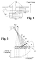
- FIG. 3 schematically shows the resulting from the inclination of the optical axes of the cameras distortion ratios within the total field of view for an off-center, tilted camera analogous to the mentioned in the above ESA report constellation of five fan-shaped cameras.
- Figure 3 neglected the surface curvature of the celestial body and considered only the tangent plane, so that the influence of the curvature of the celestial body on the image distortion in this description initially ignored.
- the superposition (assignment of pixels of the same spatial position on the surface of the celestial body) of the individual image recordings is referred to as co-registration, which must have a certain quality of coverage of the PSFs of the individual recordings of the same target area.
- the distortion effects due to the above-described inclination of the optical axis result in constant size of the sensor elements in the sensor plane to different sized object pixels, which are detected in the projection of the surface of the celestial body, and thus to different PSFs of the pixels.
- Already due to the different size of the PSFs inevitably results in a poor co-registration of the individual overlapping, overlapping images.
- the fan-shaped arrangement of cameras to increase the swath size thus leads due to the tilt (inclination) of the optical axes of the cameras to unnecessary image distortion, which significantly complicates a co-registration of the image data.
- the invention has for its object to find a new way for image capture for remote sensing of celestial bodies, which allows a large swath, without that in the combination of several separate recording systems within the male scanning field (Field of View - FoV) different distortions of the individual images arise that complicate a subsequent co-registration of the image data.
- an optically imaging instrument has a plurality of sensor arrays in order to increase the field of view of the image acquisition in the flight direction or transversely thereto while maintaining the required resolution for each flyover
- that at least two separate cameras are arranged with mutually parallel optical axes for receiving the same field of view so that they have focal planes with same content images of the field of view of the surface of the celestial body
- that in the focal plane of each camera sensor chips are arranged so that due to the limited area of the active Sensor array of at least one sensor chip in the focal plane within a first camera sampling gap is filled by arranging at least one complementarily positioned positioned active sensor array of a sensor chip in the same image focal plane of at least one second camera, so that the entire image of the field of view for each application is completely recordable.
- the sensor arrays are advantageously arranged such that the combination of image recordings of the separate cameras seamlessly images the entire field of view to be recorded for the respective application without overlaps.
- the sensor arrays can also be expediently arranged such that the combination of image recordings of the separate cameras so completely maps the entire field of view to be recorded for the respective application that at least edge regions of the combined image recordings of the sensor arrays from different cameras overlap.
- the increased ALT swath width is preferably composed by a combination of at least two sensor arrays within at least two cameras .
- the increase of the ACT swath width becomes advantageous by composing a combination of at least two sensors within at least reached two cameras.
- the entire field of view for the respective application is composed of both ALT and ACT swaths by a combination of at least two sensor arrays within at least two cameras.
- the field of view is advantageously absorbable in the ACT swath width by gaplessly arranged sensor arrays and in the ALT swath width is at least one gap between sensor arrays for recording the measured variables at different angles to the surface of the celestial body in the direction of flight available.
- all sensor arrays of the separate cameras are read out at the same time.
- at least some groups of sensor arrays covering the field of view in ACT swath width are successively readable (e.g., to successively multiply expensive optical filters for all camera beam paths).
- the parallel aligned optical axes of the separate cameras can be advantageously realized by means of a common optical system and at least a subsequent beam splitter to produce the same image focal planes are divided.
- this design can be realized only for a few separate cameras due to the light pipe in the beam splitter.
- all cameras have one and the same optical imaging system, which has the same optically corrected image field in the focal plane.
- At least one camera preferably has an optical system which has an only partially optically corrected image field for the region of the focal plane occupied by sensor arrays and thereby differs from at least one second camera used in the optical instrument, in which another region of the Focal plane (corresponding to the complementary to the first camera existing assembly with sensor arrays) is corrected.
- the invention is based on the basic idea that the disadvantage of image distortion can be circumvented by using a plurality of mutually inclined cameras to increase the field of view of a satellite-based optical instrument only if an optical system images the entire swath width to be imaged corrected to a correspondingly large focal plane.
- the optically corrected image field can be covered by a photosensitive sensor array with cost-effective available size only to a fraction, so that multiple sensor arrays must be used, but can be installed only with considerable gaps between the sensor arrays due to the connection conditions of a sensor chip.
- the invention solves this problem by the entire corrected image field is taken by a plurality of tilted (tilted) cameras with object-side parallel optical axes, each camera in another part of the same image focal planes is equipped with a photosensitive sensor array.
- the image field can be additionally corrected. It is particularly advantageous that existing instruments for the observation of celestial bodies can be retrofitted by only the optics is adjusted according to an enlarged Schwadweite, the existing, expensive and complex in the development Fokalebenenbau devise but with modified positioning of the sensors can continue to be used.
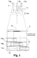
- the arrangement consists - as in Fig. 1 for three cameras 1 shown - in its basic structure of several cameras 1, which are arranged such that their optical axes 11 parallel to each other.
- the offset of the cameras 1 to each other due to the large distance (> 1 km) from the object to be imaged (surface of the celestial body 2) to no offset of the field of view 21 of the individual cameras 1 with each other.
- all the cameras 1 have the same field of view 21 on the surface of the celestial body 2 to be observed.
- the focal planes of the cameras 1 are each equipped with sensor arrays 14 only in partial areas 13a, 13b and 13c, the position of these measurable partial areas 13a, 13b and 13c in the respective focal plane 12 of each camera 1 is so different that the photosensitive surfaces of the sensor chips 14 (sensor arrays 14a, 14b and 14c) in at least one dimension of the swath width (ACT and / or ALT) cover the content-identical focal plane 12 without gaps by row by row ( ALT) or line by line (ACT) systematically (preferably with low overlap).
- the differently positioned sensor arrays 14a, 14b and 14c thus cover a larger part of the common field of view 21 (which is identical for all cameras 1) without distortions.
- Fig. 1 The generalized principle of the invention can be applied both in the direction of flight (ALT) and in the transverse direction (ACT).
- ALT direction of flight
- ACT transverse direction
- at least two focal planes 12 are required in which differently positioned sensor arrays 14 provide image data of a completely extended image field from the same visual field 21 which can be combined during co-registration of the image data without significant arithmetical equalization effort.
- combinations of the array of sensor arrays 14 for increasing the ACT swath width 31 and the ALT swath width 32 are also possible.
- At least four focal planes 21 are necessary in order to cover the extended field of view 21 without gaps. The latter will become apparent in the description below Fig. 6 explained in more detail.
- a sensor array 14 inserted in the cameras 1. This is not the case for the desired ACT error range 31.
- three sensor arrays 14 are necessary.
- the three sensor arrays 14a, 14b and 14c are arranged linearly in the ACT direction in order to record the field of view 21, which is identically imaged in the focal planes 12 of separate cameras 1, with the required ACT swath width 31.
- the sensor arrays 14a, 14b and 14c must be distributed to at least two focal planes 12 of different cameras 1, since the photosensitive sensor arrays 14 are only a fraction of the area of the sensor chips 15 and therefore can not be positioned completely within the focal plane 12 of a single camera 1, without a temporal offset of the sample (as in Fig. 2 shown) must be accepted.
- the ratio of the ACT dimension of the sensor array 14 to the ACT dimension of the entire sensor chip 15 is greater than 1: 2.
- the optically corrected focal plane 12 is elliptical in shape and sufficiently dimensioned for three sensor arrays 14 lined up.
- the described gapless arrangement of the sensor arrays 14a-14c within the virtually superimposed focal planes 12 of the separate cameras 1 does not exclude that slight overlapping of the scanned subregions 13a, 13b and 13c may occur within the same-like image of the same field of view 21.
- the distance between the sensor arrays 14a and 14c would then be smaller than an ACT sensor array length in order to close the gap in the cover of the focal plane 12 of the first camera 1 by "overlapping arrangement" of the sensor array 14b in the second camera 1 in each of the focal planes 12 of both cameras 1 the same field of view 21 is imaged by the surface of the celestial body 2.
- the simultaneously read image data from the three sensor arrays 14a-14c result in the composition in the subsequent process of co-registration a distortion-free mapping of the required swath width 3 of the dimension of an ALT sensor array width and three ACT sensor array lengths.
- the in Fig. 5 2 it is assumed that the total required ACT swath width 31 can be covered by the sensor array 14 used in the cameras 1. For the desired ALT-Schadweite 3 this was not fulfilled. In order to cover the desired total swath width 3 in the visual field 21, four sensor arrays 14 should be sufficient. In this example, the four sensor arrays 14 may also be distributed to two focal planes 12. It is assumed that the ratio of ALT dimensions from sensor array 14 to sensor chip 15 is significantly greater than 1: 2, so that a problem-free contacting of two adjacent sensor chips 15 is possible if their sensor arrays 14 have a spacing of exactly one ALT dimension of the sensor arrays 14.
- the sensor arrays 14 a and 14 c in a first camera 1 are positioned so that they are arranged in ALT swath width 32 in a row (column) and have a pitch of at most one ALT sensor dimension.
- the second camera 1 (right view of Figure 5 ) contains the sensor arrays 14b and 14d, which are arranged with respect to an existing in the focal planes 12 ALT center line 121 mirror-symmetrical to the position of the sensor arrays 14a and 14c.
- the required gap-free arrangement of the sensor arrays 14a-14d within the focal planes 12 of the separate cameras 1 virtually superimposed on the same visual field 21 also includes a slight overlap of the subareas 13a to 13d (in FIGS Fig. 5 not indicated), especially since a smaller distance between the sensor arrays 14a and 14c and 14b and 14d of less than an ALT sensor array width may be useful, for example, to check and correct the co-registration in the further processing of the image data.
- the simultaneously read-out image data from the four sensor arrays 14a-14d result in the composition in the subsequent process of co-registration a distortion-free mapping of the required swath width 3 of the dimension of an ACT sensor array length and four ALT sensor array widths.
- the total required ACT swath width 31 can be covered by two sensor array 14 inserted in the cameras 1.
- two cameras 1 top left and bottom left or right top and bottom right with respect to an ACT center line 122 of the respective focal planes 12 mirror symmetrically positioned sensor arrays 14 in the ACT direction without distance (or even with a slight overlap) and, therefore, due to the dimensions of the sensor chips 15 in the ALT direction, must have a pitch which, however, is at most an ALT sensor array width.
- eight sensor arrays 14 are required for the desired ALT Schadwte 32 in the field of view 21 (not shown) eight sensor arrays 14 are required.
- sixteen sensor arrays 14 are necessary, which are distributed on four focal planes 12 of separate cameras 1.
- two cameras 1 top left and top right, left bottom and bottom right with respect to an ALT center line 121 of the respective focal planes 12 have mirror symmetrically alternately positioned sensor arrays 14 with an ALT distance from an ALT sensor array width.
- a distortion-free imaging of the required swath width 3 of the dimension of eight ALT sensor array widths and two ACT sensor array lengths results.
- the covering of a part of the above-mentioned visual field 21 may be sufficient. This case may occur, for example, in the detection of a viewing angle-dependent reflectivity of the surface of a celestial body 2
- the cameras 1 with mutually parallel optical axes 11 may have the same or different optical imaging properties.
- the image correction of the middle camera 1 to be limited to the central part of the focal plane 12 and the image correction of the two outer cameras 1 may be limited to the correction of the lateral areas away from the optical axis 11. This can simplify the design of the individual optics.
- adapted distortion characteristics eg to take into account the surface curvature of the celestial body 2 can be adjusted.
- Another advantage of this embodiment is that the number of different camera types used can be reduced. Thus, it is possible to use a specific camera type for the respective edge region of a large swath width 3 and to use a different type of camera for the regions to be recorded which are closer to the sampling point of the nadir.
- the scan subregions 13a, 13b, 13c, etc. covered by the cameras 1 may also not be contiguously contiguous or overlapping, as the application permits, for example, in applications that detect the angular dependence of the albedo.
- This embodiment can be generated, for example, by the fact that in Fig. 7 it is assumed that the cameras 1 with the sensors 14a to 14c are arranged in the direction of flight and the central camera 1 with the sensor 14 is inactive or absent.
- the ACT swath width 31 is to be recorded as a continuous, ie continuous scanning strip. If this is the case, ACT has to perform a gapless imaging by overlapping or gapless arrangement of the sensor arrays 14 distributed over the individual cameras 1.
Abstract
Description
Die Erfindung betrifft eine Anordnung zur flugkörpergestützten Bilddatenaufnahme von der Oberfläche eines Himmelskörpers, bei der ein optisch abbildendes Instrument mehrere Sensorarrays aufweist, um für jeden Überflug das Gesichtsfeld der Bildaufnahme in Flugrichtung oder quer dazu unter Beibehaltung der erforderlichen Auflösung zu vergrößern
Sie findet vorwiegend Anwendung zur Erleichterung der Co-Registrierung von mehrkanalig (z.B. spektral oder polarisationsoptisch unterschiedlich) aufgenommenen Bilddaten von der Oberfläche eines Himmelskörpers, insbesondere der Erde.The invention relates to an arrangement for missile-based image data recording of the surface of a celestial body, in which an optically imaging instrument has a plurality of sensor arrays in order to increase the field of view of the image recording in the flight direction or transversely thereto while maintaining the required resolution for each flyover
It finds predominantly application for facilitating the co-registration of multi-channel (eg spectrally or polarization optically different) recorded image data from the surface of a celestial body, in particular the earth.
Für satellitengestützte optische Beobachtungsinstrumente zur Aufnahme der Oberfläche von Himmelskörpern wird häufig eine hohe Flächenabdeckung gefordert.
Zur Charakterisierung des Abtastfeldes bei einer Sensorauslesung wird der Begriff Schwadweite eingeführt und so verstanden, dass zusätzlich zum herkömmlich benutzten Begriff der Schwadbreite als Breite der Abtastspur satellitengestützter Instrumente quer zur Flugrichtung (accross track - ACT)eine Abtastlänge in Flugrichtung (along track - ALT) definiert ist, um das gesamte Gesichtsfeld (Field of View) einer Sensorarrayauslesung zu beschreiben. Die Breite der Abtastspur (ACT) wird im Folgenden mit "ACT-Schwadweite" und die Länge der Abtastfensters (ALT) mit "ALT-Schwadweite" bezeichnet.For satellite-based optical observation instruments for recording the surface of celestial bodies, a high surface coverage is often required.
For characterizing the scanning field in a sensor reading, the term swathing is introduced and understood that in addition to the conventionally used term of swath width as the width of the Abtastspur satellite-based instruments transverse to the direction of flight (accross track - ACT) defines a scan length in the direction of flight (ALT) is to describe the entire field of view of a sensor array readout. The width of the scanning track (ACT) is hereinafter referred to as "ACT swath width" and the length of the scanning window (ALT) is referred to as "ALT swath width".
Im Stand der Technik der satellitengestützten Instrumente kommen beispielsweise Pushbroom-Abtastsysteme zum Einsatz, die auf einer Kamera mit einem einzelnen Sensor (Matrix- oder Zeilenarray) basieren. Diese sind häufig nicht ausreichend, so dass mehrere Sensorarrays aneinandergesetzt werden, um beispielsweise die ACT-Schwadweite zu vergrößern.
Eine solche Maßnahme, wie sie z.B.
Such a measure, such as
Ein anderer Lösungsansatz, um eine größere ACT-Schwadweite zu erreichen, wird in einem ESA-Report ("
Der Begriff "optische Achse" stellt dabei im klassischen Sinne eine Gerade dar, die mit der Symmetrieachse eines reflektierenden oder refraktiven optischen Elements übereinstimmt (siehe z.B.
- 1) Die Gesamtheit der Abbildungseigenschaften eines realen optischen Systems sei durch ein virtuelles symmetrisches System darstellbar.
- 2) Für das virtuelle symmetrische System wird die optische Achse im klassischen Sinne als Symmetrieachse des Systems definiert.
- 1) The entirety of the imaging properties of a real optical system can be represented by a virtual symmetrical system.
- 2) For the virtual symmetric system, the optical axis is defined in the classical sense as the symmetry axis of the system.
Bei einem System, das das geforderte Gesamtgesichtsfeld mit einer einzelnen Kamera abdeckt, würden keinerlei Verzerrungen auftreten und somit die Bildpunkte a5, a6, a7 und a8 gleich groß sein. Diese Verzerrungsfreiheit ist innerhalb des Gesichtsfeldes einer um den Winkel α geneigten Kamera nicht mehr gegeben. Wie in
Viele Aufgaben der Fernerkundung von Himmelskörpern lassen sich jedoch nur lösen, indem ein- und dasselbe Objektpixel auf der Oberfläche des Himmelskörpers unter verschiedenen Bedingungen (Spektralbereich, Polarisationsrichtung, Blickrichtung) aufgenommen wird. Dabei ist es essentiell wichtig, dass die in unterschiedlichen Wellenlängen und gegebenenfalls bei optisch unterschiedlicher Polarisationsrichtung aufgenommenen Pixeldaten vor der weiteren Verarbeitung exakt übereinander gelegt werden. Ziel ist es also, die Punkt-Verwaschungs-Funktionen (PSF - Point Spread Function) der einzelnen Aufnahmen zu einem möglichst großen Prozentsatz in Übereinstimmung zu bringen. Die Überlagerung (Zuordnung von Pixeln gleicher Ortslage auf der Oberfläche des Himmelskörpers) der einzelnen Bildaufnahmen wird als Co-Registrierung bezeichnet, die eine bestimmte Güte der Überdeckung der PSFs der einzelnen Aufnahmen ein- und desselben Zielbereiches aufweisen muss.
Die Verzerrungseffekte durch die oben beschriebene Neigung der optischen Achse führen bei konstanter Größe der Sensorelemente in der Sensorebene zu unterschiedlich großen Objektpixeln, die bei der Projektion von der Oberfläche des Himmelskörpers erfasst werden, und damit zu unterschiedlichen PSFs der Pixel. Bereits durch die unterschiedliche Größe der PSFs ergibt sich zwangsläufig eine schlechte Co-Registrierung der einzelnen zu überlagernden, sich überlappenden Bildaufnahmen.In a system covering the required total field of view with a single camera, no distortion would occur and thus the pixels a5, a6, a7 and a8 would be the same size. This freedom from distortion is no longer present within the field of view of a camera inclined by the angle α. As in
However, many tasks of remote sensing of celestial bodies can only be solved by taking one and the same object pixel on the surface of the celestial body under different conditions (spectral range, polarization direction, viewing direction). In this case, it is essential that the pixel data recorded in different wavelengths and optionally in optically different polarization directions are exactly superimposed before further processing. So the goal is to use the point-blurring features (PSF - Point Spread Function) of the individual recordings to the largest possible percentage match. The superposition (assignment of pixels of the same spatial position on the surface of the celestial body) of the individual image recordings is referred to as co-registration, which must have a certain quality of coverage of the PSFs of the individual recordings of the same target area.
The distortion effects due to the above-described inclination of the optical axis result in constant size of the sensor elements in the sensor plane to different sized object pixels, which are detected in the projection of the surface of the celestial body, and thus to different PSFs of the pixels. Already due to the different size of the PSFs inevitably results in a poor co-registration of the individual overlapping, overlapping images.
Die fächerförmige Anordnung von Kameras zur Vergrößerung der Schwadweite führt also aufgrund der Verkippung (Neigung) der optischen Achsen der Kameras zu unnötigen Abbildungsverzerrungen, die eine Co-Registrierung der Bilddaten erheblich erschweren.The fan-shaped arrangement of cameras to increase the swath size thus leads due to the tilt (inclination) of the optical axes of the cameras to unnecessary image distortion, which significantly complicates a co-registration of the image data.
Der Erfindung liegt die Aufgabe zugrunde, eine neue Möglichkeit für die Bildaufnahme zur Fernerkundung von Himmelskörpern zu finden, die eine große Schwadweite gestattet, ohne dass bei der Verknüpfung von mehreren separaten Aufnahmesystemen innerhalb des aufzunehmenden Abtastfeldes (Field of View - FoV) unterschiedliche Verzerrungen der Einzelaufnahmen entstehen, die eine nachfolgende Co-Registrierung der Bilddaten erschweren.The invention has for its object to find a new way for image capture for remote sensing of celestial bodies, which allows a large swath, without that in the combination of several separate recording systems within the male scanning field (Field of View - FoV) different distortions of the individual images arise that complicate a subsequent co-registration of the image data.
Erfindungsgemäß wird die Aufgabe bei einer Anordnung zur flugkörpergestützten Bilddatenaufnahme von der Oberfläche eines Himmelskörpers, bei der ein optisch abbildendes Instrument mehrere Sensorarrays aufweist, um für jeden Überflug das Gesichtsfeld der Bildaufnahme in Flugrichtung oder quer dazu unter Beibehaltung der erforderlichen Auflösung zu vergrößern, dadurch gelöst, dass mindestens zwei separate Kameras mit zueinander parallelen optischen Achsen zur Aufnahme desselben Gesichtsfeldes angeordnet sind, so dass sie Fokalebenen mit inhaltsgleichen Bildern des Gesichtsfeldes von der Oberfläche des Himmelskörpers aufweisen, und dass in der Fokalebene jeder Kamera Sensorchips so angeordnet sind, dass eine aufgrund der beschränkten Fläche des aktiven Sensorarrays des mindestens einen Sensorchips in der Fokalebene innerhalb einer ersten Kamera vorhandene Abtastlücke durch das Anordnen von wenigstens einem komplementär versetzt positionierten aktiven Sensorarray eines Sensorchips in der abbildungsgleichen Fokalebene mindestens einer zweiten Kamera ausgefüllt ist, so dass das gesamte für die jeweilige Anwendung aufzunehmende Bild des Gesichtsfeldes lückenlos aufnehmbar ist.According to the invention, in an arrangement for missile-supported image data acquisition from the surface of a celestial body, in which an optically imaging instrument has a plurality of sensor arrays in order to increase the field of view of the image acquisition in the flight direction or transversely thereto while maintaining the required resolution for each flyover, that at least two separate cameras are arranged with mutually parallel optical axes for receiving the same field of view so that they have focal planes with same content images of the field of view of the surface of the celestial body, and that in the focal plane of each camera sensor chips are arranged so that due to the limited area of the active Sensor array of at least one sensor chip in the focal plane within a first camera sampling gap is filled by arranging at least one complementarily positioned positioned active sensor array of a sensor chip in the same image focal plane of at least one second camera, so that the entire image of the field of view for each application is completely recordable.
Vorteilhaft sind die Sensorarrays so angeordnet, dass die Kombination von Bildaufnahmen der separaten Kameras das gesamte für die jeweilige Anwendung aufzunehmende Gesichtsfeld ohne Überlappungen lückenlos abbildet. Die Sensorarrays können aber auch zweckmäßig so angeordnet sein, dass die Kombination von Bildaufnahmen der separaten Kameras das gesamte für die jeweilige Anwendung aufzunehmende Gesichtsfeld derart lückenlos abbildet, dass sich mindestens Randbereiche der kombinierten Bildaufnahmen der Sensorarrays aus unterschiedlichen Kameras überlappen.The sensor arrays are advantageously arranged such that the combination of image recordings of the separate cameras seamlessly images the entire field of view to be recorded for the respective application without overlaps. However, the sensor arrays can also be expediently arranged such that the combination of image recordings of the separate cameras so completely maps the entire field of view to be recorded for the respective application that at least edge regions of the combined image recordings of the sensor arrays from different cameras overlap.
In einer Ausführung zur Erhöhung der Schwadweite in Flugrichtung, bei der das gesamte für die jeweilige Anwendung abzubildende Gesichtsfeld als ACT-Schwadweite mittels nur einer Sensorarraylänge aufnehmbar ist, wird die erhöhte ALT-Schwadweite vorzugsweise durch eine Kombination von mindestens zwei Sensorarrays innerhalb mindestens zweier Kameras zusammengesetzt.
In einer Ausführung zur Erhöhung der Schwadweite quer zur Flugrichtung, bei der das gesamte für die jeweilige Anwendung abzubildende Gesichtsfeld als ALT-Schwadweite mittels nur einer Sensorarraybreite aufnehmbar ist, wird die Erhöhung der ACT-Schwadweite vorteilhaft durch Zusammensetzung einer Kombination von mindestens zwei Sensoren innerhalb mindestens zweier Kameras erreicht.In an embodiment for increasing the swath width in the direction of flight, in which the entire field of view for the respective application can be recorded as ACT swath width by means of only one sensor array length, the increased ALT swath width is preferably composed by a combination of at least two sensor arrays within at least two cameras ,
In an embodiment for increasing the swath width transversely to the direction of flight, in which the entire field of view for the respective application can be recorded as ALT swath width by means of only one sensor array width, the increase of the ACT swath width becomes advantageous by composing a combination of at least two sensors within at least reached two cameras.
Für eine erhöhte Schwadweite in Flugrichtung und quer dazu ist das gesamte für die jeweilige Anwendung abzubildende Gesichtsfeld sowohl in ALT- als auch in ACT-Schwadweite jeweils durch eine Kombination von mindestens zwei Sensorarrays innerhalb mindestens zweier Kameras zusammengesetzt.For an increased swath width in the direction of flight and across, the entire field of view for the respective application is composed of both ALT and ACT swaths by a combination of at least two sensor arrays within at least two cameras.
In einer speziellen Gestaltung zur Aufnahme winkelabhängiger optischer Messgrößen ist das abzubildende Gesichtsfeld vorteilhaft in der ACT-Schwadweite durch lückenlos angeordnete Sensorarrays aufnehmbar und in der ALT-Schwadweite ist wenigstens eine Lücke zwischen Sensorarrays für die Aufnahme der Messgrößen unter unterschiedlichen Winkeln zur Oberfläche des Himmelskörpers in Flugrichtung vorhanden.In a special design for recording angle-dependent optical measurement quantities, the field of view is advantageously absorbable in the ACT swath width by gaplessly arranged sensor arrays and in the ALT swath width is at least one gap between sensor arrays for recording the measured variables at different angles to the surface of the celestial body in the direction of flight available.
In einer besonderen Vorzugsvariante werden alle Sensorarrays der separaten Kameras zeitgleich ausgelesen. Es kann sich jedoch aus technologischen und/oder Kostengründen als zweckmäßig erweisen, dass wenigstens einige Gruppen von Sensorarrays, die das Gesichtsfeld in ACT-Schwadweite lückenlos abdecken, aufeinanderfolgend auslesbar sind (z.B. um teure optische Filter für alle Kamerastrahlengänge aufeinanderfolgend mehrfach zu nutzen).In a special preferred variant, all sensor arrays of the separate cameras are read out at the same time. However, for technological and / or cost reasons, it may prove expedient that at least some groups of sensor arrays covering the field of view in ACT swath width are successively readable (e.g., to successively multiply expensive optical filters for all camera beam paths).
Um die für das Grundprinzip der Erfindung erforderlichen inhaltsgleichen Fokalebenen zu schaffen, können die parallel ausgerichteten optischen Achsen der separaten Kameras vorteilhaft mittels eines gemeinsamen optischen System realisiert und mindestens ein nachfolgender Strahlteiler zur Erzeugung der abbildungsgleichen Fokalebenen aufgeteilt werden. Diese Gestaltung lässt sich jedoch aufgrund der Lichtleitung im Strahlteiler nur für wenige separate Kameras realisieren.
In einer anderen zweckmäßigen Realisierungsform haben alle Kameras ein und dasselbe optische Abbildungssystem, das in der Fokalebene das gleiche optisch korrigierte Bildfeld aufweist.
Besonders vorteilhaft erweist es sich jedoch, wenn die optischen Systeme der separaten Kameras, da deren Fokalebenen nur teilweise mit abtastenden Sensorarrays bestückt sind, nicht flächendeckend vollständig optisch korrigierte Fokalebenen aufweisen. In einem solchen Fall weist vorzugsweise mindestens eine Kamera ein optisches System auf, das ein nur teilweise optisch korrigiertes Bildfeld für den mit Sensorarrays belegten Bereich der Fokalebene besitzt und sich dadurch von mindestens einer zweiten im optischen Instrument verwendeten Kamera unterscheidet, in der ein anderer Bereich der Fokalebene (entsprechend der komplementär zur ersten Kamera vorhandenen Bestückung mit Sensorarrays) korrigiert ist.In order to provide the same content focal planes required for the basic principle of the invention, the parallel aligned optical axes of the separate cameras can be advantageously realized by means of a common optical system and at least a subsequent beam splitter to produce the same image focal planes are divided. However, this design can be realized only for a few separate cameras due to the light pipe in the beam splitter.
In another expedient embodiment, all cameras have one and the same optical imaging system, which has the same optically corrected image field in the focal plane.
However, it proves particularly advantageous if the optical systems of the separate cameras, since their focal planes only partially with scanning Sensor arrays are populated, not full coverage have completely optically corrected focal planes. In such a case, at least one camera preferably has an optical system which has an only partially optically corrected image field for the region of the focal plane occupied by sensor arrays and thereby differs from at least one second camera used in the optical instrument, in which another region of the Focal plane (corresponding to the complementary to the first camera existing assembly with sensor arrays) is corrected.
Die Erfindung basiert auf der Grundüberlegung, dass der Nachteil der Bildverzerrung durch Einsatz mehrerer gegeneinander geneigter Kameras zur Gesichtsfeldvergrößerung eines satellitengestützten optischen Instruments nur umgangen werden kann, wenn eine Optik die gesamte abzubildende Schwadweite auf eine entsprechend große Fokalebene korrigiert abbildet. Das optisch korrigierte Bildfeld kann dabei jedoch von einem lichtempfindlichen Sensorarray mit kostengünstiger verfügbarer Größe nur zu einem Bruchteil abgedeckt werden, so dass mehrere Sensorarrays eingesetzt werden müssen, die sich jedoch aufgrund der Anschlussbedingungen eines Sensorchips nur mit erheblichen Lücken zwischen den Sensorarrays installieren lassen. die Erfindung löst dieses Problem, indem das gesamte korrigierte Bildfeld durch mehrere nicht zueinander verkippte (geneigte) Kameras mit objektseitig parallelen optischen Achsen aufgenommen wird, wobei in jeder Kamera jeweils ein anderer Teil der abbildungsgleichen Fokalebenen mit einem lichtempfindlichen Sensorarray bestückt wird. Mit Hilfe von weiteren Methoden zur Unterdrückung nicht erwünschter Abbildungsverzerrungen (z.B. zur Kompensation der Oberflächenkrümmung des Himmelskörpers gemäß der nicht vorveröffentlichten Patentanmeldung
Mit der erfindungsgemäßen Lösung ist es möglich, eine Bildaufnahme zur Fernerkundung von Himmelskörpern zu realisieren, die eine große Schwadweite gestattet, ohne dass bei der Verknüpfung von mehreren separaten Aufnahmesystemen innerhalb des aufzunehmenden Gesichtsfeldes unterschiedliche Verzerrungen der Einzelaufnahmen entstehen, die eine nachfolgende Co-Registrierung der Bilddaten erschweren.With the solution according to the invention, it is possible to realize an image acquisition for remote sensing of celestial bodies, which allows a large swath width, without resulting in the combination of several separate recording systems within the male field of vision different distortions of the individual images, the subsequent co-registration of the image data difficult.
Die Erfindung soll nachstehend anhand von Ausführungsbeispielen näher erläutert werden. Die Zeichnungen zeigen:
- Fig. 1:
- eine Prinzipansicht der erfindungsgemäßen Anordnung,
- Fig.2:
- eine Darstellung des Standes der Technik mit überlappenden Sensorschaltkreisen,
- Fig. 3:
- eine Darstellung der Verzerrung der optischen Abbildung bei geneigter optischer Achse gemäß dem Stand der Technik, [ehem. Abb. 2a]
- Fig.4:
- eine Variante der Erfindung unter Verwendung von zwei Kameras, bei denen die ACT-Schwadweite durch eine ALT einzeilige Anordnung von Sensorarrays erhöht wird, bei der eine Kamera zwei äußere Teilbereiche und die andere Kamera den dazwischen liegenden mittleren Teilbereich der Fokalebene abdeckt,
- Fig. 5:
- eine Ausgestaltung der Erfindung unter Verwendung von zwei Kameras, bei denen die ALT-Schwadweite durch eine ALT vierzeilige Anordnung von Sensorarrays erhöht wird, bei der jede Kamera zwei ALT außermittig angeordnete Sensorarrays so aufweist, dass die technologisch bedingte ALT-Lücke jeweils durch die andere spiegelsymmetrisch mit Sensorarrays bestückte Kamera geschlossen wird,
- Fig. 6:
- eine Ausgestaltung der Erfindung mit erhöhter ACT- und ALT-Schwadweite unter Verwendung von vier Kameras, bei denen sich vier Kameras mit jeweils vier versetzt angeordneten Sensorarrays zu einer ACT zweireihigen und ALT achtzeiligen lückenlosen Konfiguration ergänzen,
- Fig. 7:
- eine Darstellung mit drei Kameras, die bei gleichem Gesichtsfeld (FoV) zur Erhöhung der Schadweite so angeordnet und aufgebaut sind, dass die Kameras aufgrund ihrer unterschiedlichen Abtastbereiche innerhalb der äquivalenten Fokalebenen lediglich partiell vollständig korrigierte Abbildungsoptiken aufweisen.
- Fig. 1:
- a schematic view of the arrangement according to the invention,
- Figure 2:
- a representation of the prior art with overlapping sensor circuits,
- 3:
- a representation of the distortion of the optical image with inclined optical axis according to the prior art, [ehem. Fig. 2a]
- Figure 4:
- a variant of the invention using two cameras, in which the ACT swath width is increased by an ALT single-row arrangement of sensor arrays, in which one camera covers two outer subareas and the other camera covers the intermediate subarea of the focal plane,
- Fig. 5:
- an embodiment of the invention using two cameras in which the ALT swath is increased by an ALT four-line array of sensor arrays in which each camera has two ALT eccentrically arranged sensor arrays so that the technologically induced ALT gap in each case by the other mirror-symmetrical camera equipped with sensor arrays is closed,
- Fig. 6:
- an embodiment of the invention with increased ACT and ALT swath width using four cameras, in which four cameras, each with four staggered sensor arrays to complement an ACT double-row and ALT eight-row gapless configuration,
- Fig. 7:
- a representation with three cameras, which are arranged and constructed with the same field of view (FoV) to increase the FOV so that the cameras have only partially completely corrected imaging optics due to their different scanning within the equivalent focal planes.
Die Anordnung besteht - wie in
In Summe decken die unterschiedlich positionierten Sensorarrays 14a, 14b und 14c somit einen größeren Teil des gemeinsamen (für alle Kameras 1 übereinstimmenden) Gesichtsfeldes 21 ohne Verzerrungen ab. In
In sum, the differently positioned
Das in
Natürlich sind auch Kombinationen der Anordnung von Sensorarrays 14 für die Vergrößerung der ACT-Schwadweite 31 und der ALT-Schwadweite 32 möglich. Dabei sind mindestens vier Fokalebenen 21 notwendig, um das erweiterte Gesichtsfeld 21 lückenlos abzudecken. Letzteres wird in der nachfolgenden Beschreibung zu
Of course, combinations of the array of
Für die Ausführung gemäß
Die drei Sensorarrays 14a, 14b und 14c sind in ACT-Richtung linear angeordnet, um das Gesichtsfeld 21, das in den Fokalebenen 12 separater Kameras 1 identisch abgebildet wird, lückenlos mit der geforderten ACT-Schwadweite 31 aufzunehmen. Dazu müssen die Sensorarrays 14a, 14b und 14c auf wenigstens zwei Fokalebenen 12 unterschiedlicher Kameras 1 verteilt werden, da die lichtempfindlichen Sensorarrays 14 nur einen Bruchteil der Fläche der Sensorchips 15 betragen und sich deshalb nicht innerhalb der Fokalebene 12 einer einzigen Kamera 1 lückenlos positionieren lassen, ohne dass ein zeitlicher Versatz der Abtastung (wie in
In der in
The three
In the in
Für das in
Die beschriebene lückenlose Anordnung der Sensorarrays 14a-14c innerhalb der virtuell überlagerten Fokalebenen 12 der separaten Kameras 1, schließt nicht aus, dass geringfügige Überlappung der abgetasteten Teilbereiche 13a, 13b und 13c innerhalb der inhaltsgleichen Abbildung desselben Gesichtsfeldes 21 auftreten dürfen. Dabei wäre dann der Abstand zwischen den Sensorarrays 14a und 14c kleiner als eine ACT-Sensorarraylänge zu wählen, um die Lücke in der Abdeckung der Fokalebene 12 der ersten Kamera 1 durch "überlappende Anordnung" des Sensorarrays 14b in der zweiten Kamera 1 zu schließen, da in die Fokalebenen 12 beider Kameras 1 jeweils dasselbe Gesichtsfeld 21 von der Oberfläche des Himmelskörpers 2 abgebildet wird.The described gapless arrangement of the
Die gleichzeitig ausgelesenen Bilddaten aus den drei Sensorarrays 14a-14c ergeben bei der Zusammensetzung im nachfolgenden Prozess der Co-Registrierung eine verzerrungsfreie Abbildung der geforderten Schwadweite 3 von der Dimension einer ALT-Sensorarraybreite und drei ACT-Sensorarraylängen.The simultaneously read image data from the three
In der Ausführung, die in
In diesem Beispiel können die vier Sensorarrays 14 ebenfalls auf zwei Fokalebenen 12 verteilt werden. Dabei wird unterstellt, dass das Verhältnis der ALT-Dimensionen von Sensorarray 14 zu Sensorchip 15 deutlich größer als 1:2 ist, so dass eine problemlose Kontaktierung von zwei benachbarten Sensorchips 15 möglich ist, wenn deren Sensorarrays 14 einen Abstand von genau einer ALT-Dimension der Sensorarrays 14 aufweisen.
In den Fokalebenen 12 von zwei separaten, ACT benachbart positionierten Kameras 1 werden die Sensorarrays 14a und 14c in einer ersten Kamera 1 (linke Darstellung von
Die geforderte lückenlose Anordnung der Sensorarrays 14a-14d innerhalb der aufgrund desselben abgebildeten Gesichtsfeldes 21 virtuell überlagerten Fokalebenen 12 der separaten Kameras 1 schließt auch hier geringfügige Überlappung der von den Sensorarrays 14a bis 14d abgetasteten Teilbereiche 13a bis 13d (in
Die gleichzeitig ausgelesenen Bilddaten aus den vier Sensorarrays 14a-14d ergeben bei der Zusammensetzung im nachfolgenden Prozess der Co-Registrierung eine verzerrungsfreie Abbildung der geforderten Schwadweite 3 von der Dimension einer ACT-Sensorarraylänge und vier ALT-Sensorarraybreiten.In the design, the in
In this example, the four
In the
The required gap-free arrangement of the
The simultaneously read-out image data from the four
In der Ausgestaltung gemäß
Für die gewünschte ALT-Schadwte 32 im Gesichtsfeld 21 (nicht dargestellt) sollen acht Sensorarrays 14 erforderlich sein. Um die gesamte Schwadweite 3 lückenlos abzudecken, sind sechzehn Sensorarrays 14 notwendig, die auf vier Fokalebenen 12 separater Kameras 1 verteilt werden. Dabei haben je zwei Kameras 1 (links oben und rechts oben bzw. links unten und rechts unten) bezüglich einer ALT-Mittellinie 121 der jeweiligen Fokalebenen 12 spiegelsymmetrisch abwechselnd positionierte Sensorarrays 14 mit einem ALT-Abstand von einer ALT-Sensorarraybreite.
Beim gleichzeitigen Auslesen der Bilddaten aus allen sechzehn Sensorarrays 14 ergibt sich im nachfolgenden Prozess der Co-Registrierung eine verzerrungsfreie Abbildung der geforderten Schwadweite 3 der Dimension von acht ALT-Sensorarraybreiten und zwei ACT-Sensorarraylängen.In the embodiment according to
For the desired ALT Schadwte 32 in the field of view 21 (not shown) eight
In the case of the simultaneous readout of the image data from all sixteen
Natürlich muss nicht das gesamte von den Optiken der Kameras 1 in den Fokalebenen 12 zur Verfügung gestellte Gesichtsfeld 21 durch die Gesamtheit aller Sensorarrays 14 abgedeckt werden. Je nach Anwendung kann auch die Abdeckung eines Teils des oben genannten Gesichtsfeldes 21 ausreichend sein. Dieser Fall kann beispielsweise bei der Erfassung eines blickwinkelabhängigen Reflexionsvermögens der Oberfläche eines Himmelskörpers 2 auftretenOf course, not all the
In verschiedenen Ausprägungen der Erfindung können die Kameras 1 mit zueinander parallelen optischen Achsen 11 gleiche oder auch unterschiedliche optische Abbildungseigenschaften besitzen. So muss für jede einzelne Kamera 1 lediglich das von ihrem Sensorarray 14 genutzte Teilgesichtsfeld optisch korrigiert werden, nicht jedoch das gesamte Gesichtsfeld 21 der gesamten Kamera 1. Für die in
Ein weiterer Vorteil dieser Ausgestaltung liegt darin, dass die Anzahl der verschiedenen eingesetzten Kameratypen reduziert werden kann. So ist es möglich, für den jeweiligen Randbereich einer großen Schwadweite 3 einen bestimmten Kameratyp zu benutzen und für die aufzunehmenden Gebiete, die näher am Abtastpunkt des Nadir sind, einen anderen Kameratyp zu verwenden.Another advantage of this embodiment is that the number of different camera types used can be reduced. Thus, it is possible to use a specific camera type for the respective edge region of a large swath width 3 and to use a different type of camera for the regions to be recorded which are closer to the sampling point of the nadir.
Natürlich können die von den Kameras 1 abgedeckten Abtast-Teilbereiche 13a, 13b, 13c usw. auch nicht lückenlos aneinandergrenzend oder überlappend sein, wenn die Anwendung dies zulässt, zum Beispiel bei Anwendungen, die die Winkelabhängigkeit des Albedo erfassen. Hierbei kann es ausreichend sein, dass durch einzelne (oder auch zusammenwirkende) Sensorflächen gebildete Teilbereiche 13a und 13c der abgebildeten Schwadweite 3 in ALT-Richtung ein nicht lückenloses Gesamtbild erzeugen. Diese Ausführung kann z.B. dadurch erzeugt werden, dass in
In ACT Richtung muss dagegen eine lückenlose Abdeckung gegeben sein, insofern dies zur Erfüllung der Beobachtungsaufgabe vonnöten ist. In der Regel soll die ACT-Schwadweite 31 ein durchgehender, d.h. lückenloser Abtaststreifen aufgenommen werden. Ist dies der Fall, so muss ACT eine lückenlose Abbildung durch Überlappung oder lückenlose Anordnung der Sensorarrays 14 verteilt über die einzelnen Kameras 1 erfolgen.Of course, the
In the ACT direction, on the other hand, there must be complete coverage, insofar as this is necessary to fulfill the observation task. As a rule, the ACT swath width 31 is to be recorded as a continuous, ie continuous scanning strip. If this is the case, ACT has to perform a gapless imaging by overlapping or gapless arrangement of the
Im Idealfall werden alle Sensorarrays 14a, 14b, 14c usw. innerhalb aller Kameras 1 gleichzeitig belichtet. In diesem Fall ergibt sich eine nahezu perfekte Co-Registrierung der Rohdaten. Konstruktive Randbedingungen können dazu führen, dass von diesem Idealfall abgewichen werden muss.
Ist in einem Abtastsystem aus beispielsweise zwei Kameras 1 die Möglichkeit zur Aufnahme unterschiedlicher Spektralkanäle oder Polarisationsrichtungen über ein Filterrad implementiert, müssten - um den Idealfall der gleichzeitigen Bildaufnahme einzustellen - die verschiedenen Filter im Filterrad dupliziert vorliegen, um im selben Spektralbereich die gleichzeitige Aufnahme der Kameras 1 zu ermöglichen. Hierbei ergibt sich der Nachteil, dass für die beiden Kameras 1 unterschiedliche Filterpaare Verwendung finden, zwischen denen erhöhte Anforderungen an die Homogenität der Filter zu stellen sind, so dass der Vorteil der gleichzeitigen Bildaufnahme gegenüber dem Nachteil der wesentlich erhöhten Aufwendungen für die doppelte Filterausstattung abgewägt werden muss.Ideally, all
If the possibility for recording different spectral channels or polarization directions via a filter wheel is implemented in a scanning system comprising, for example, two
Letztendlich kann es also vorteilhaft sein, abweichend vom Idealfall der gleichzeitigen Aufnahme, komplementäre Bildbereiche 13a, 13b, usw. zeitversetzt aufzunehmen und den aufgrund der translatorischen Flugbewegung des das Kamerasystem tragenden Flugkörpers eingefügten räumlichen Versatz zwischen den Aufnahmen der einzelnen Kameras 1 durch angepasste Platzierung der Sensorarrays 14a, 14b usw. und eine zeit- bzw. ortsgerecht verkämmte Bilddatenverknüpfung zu kompensieren, so dass im Ergebnis wiederum eine der Anwendung entsprechende, lückenlose (oder überlappende) Gesamtbildaufnahme aus den Einzelabtastungen der Sensorarrays 14a, 14b usw. der separaten Kameras 1 entsteht.Ultimately, it may thus be advantageous, unlike the ideal case of simultaneous recording, to record
- 11
- Kameracamera
- 1111
- optische Achseoptical axis
- 1212
- Fokalebenefocal plane
- 121121
- ALT-MittellinieALT centerline
- 122122
- ACT-MittellinieACT centerline
- 13a, b, c13a, b, c
- Teilbereich (der Fokalebene)Partial area (the focal plane)
- 1414
- Sensorarraysensor array
- 14a, b, c, d14a, b, c, d
- Sensorarraysensor array
- 1515
- Sensorchipsensor chip
- 1616
- Anschlüsseconnections
- 22
- Oberfläche (des Himmelskörpers)Surface (of the celestial body)
- 2121
- Gesichtsfeld (Field of View)Field of View
- 33
- SchwadweiteSchwadweite
- 3131
- ACT-SchwadweiteACT Schwadweite
- 3232
- ALT-SchwadweiteALT Schwadweite
Claims (12)
die Sensorarrays (14) so angeordnet sind, dass die Kombination von Bildaufnahmen der separaten Kameras (1) das gesamte für die jeweilige Anwendung aufzunehmende Gesichtsfeld (21) ohne Überlappungen lückenlos abbildet.Arrangement according to claim 1, characterized in that
the sensor arrays (14) are arranged such that the combination of image recordings of the separate cameras (1) seamlessly images the entire field of view (21) to be recorded for the respective application without overlaps.
die Sensorarrays (14) so angeordnet sind, dass die Kombination von Bildaufnahmen der separaten Kameras (1) das gesamte für die jeweilige Anwendung aufzunehmende Gesichtsfeld (21) derart lückenlos abbildet, dass sich mindestens Randbereiche der kombinierten Bildaufnahmen der Sensorarrays (14) aus unterschiedlichen Kameras (1) überlappen.Arrangement according to claim 1, characterized in that
the sensor arrays (14) are arranged in such a way that the combination of image recordings of the separate cameras (1) so completely maps the entire field of view (21) to be recorded for the respective application that At least edge regions of the combined image recordings of the sensor arrays (14) from different cameras (1) overlap.
das gesamte für die jeweilige Anwendung abzubildende Gesichtsfeld (21) als ALT-Schwadweite (32) mittels eines Sensorarrays (14) aufnehmbar ist und die ACT-Schwadweite (31) durch eine Kombination von mindestens zwei Sensorarrays (14a, 14c; 14b) innerhalb mindestens zweier Kameras (1) zusammengesetzt ist.Arrangement according to claim 1, characterized in that
the entire field of view (21) to be imaged for the respective application can be recorded as ALT swath width (32) by means of a sensor array (14) and the ACT swath width (31) by a combination of at least two sensor arrays (14a, 14c, 14b) within at least two cameras (1) is composed.
das gesamte für die jeweilige Anwendung abzubildende Gesichtsfeld (21) als ACT-Schwadweite (31) mittels eines Sensorarrays (14) aufnehmbar ist und die ALT-Schwadweite (32) durch eine Kombination von mindestens zwei Sensorarrays (14a, 14c; 14b, 14d) innerhalb mindestens zweier Kameras (1) zusammengesetzt ist.Arrangement according to claim 1, characterized in that
the total field of view (21) to be imaged for the respective application is recordable as an ACT swath (31) by means of a sensor array (14) and the ALT swath (32) by a combination of at least two sensor arrays (14a, 14c, 14b, 14d) within at least two cameras (1) is composed.
das gesamte für die jeweilige Anwendung abzubildende Gesichtsfeld (21) sowohl in ACT- als auch in ALT-Schwadweite (31; 32) jeweils durch eine Kombination von mindestens zwei Sensorarrays (14a, 14b, ...) innerhalb mindestens zweier Kameras (1) zusammengesetzt ist.Arrangement according to claim 1, characterized in that
the entire field of view (21) to be imaged for the respective application both in the ACT and ALT swaths (31; 32) in each case by a combination of at least two sensor arrays (14a, 14b, ...) within at least two cameras (1) is composed.
das abzubildende Gesichtsfeld (21) für die Aufnahme winkelabhängiger optischer Messgrößen in der ACT-Schwadweite (31) durch lückenlos angeordnete Sensorarrays (14) aufnehmbar ist und in der ALT-Schwadweite (32) wenigstens eine Lücke zwischen Sensorarrays (14) für die Aufnahme von Messgrößen unter unterschiedlichen Winkeln zur Oberfläche des Himmelskörpers (2) vorhanden ist.Arrangement according to claim 1, characterized in that
the visual field (21) to be imaged for recording angle-dependent optical measured variables in the ACT swath (31) can be accommodated by gapless sensor arrays (14) and at least one gap between sensor arrays (14) in the ALT swath width (32) for recording Measured variables at different angles to the surface of the celestial body (2) is present.
alle Sensorarrays (14) zeitgleich auslesbar sind.Arrangement according to claim 1, characterized in that
all sensor arrays (14) are simultaneously readable.
wenigstens Gruppen von Sensorarrays (14), die das Gesichtsfeld (21) in ACT-Schwadweite (31) lückenlos abdecken, aufeinanderfolgend auslesbar sind.Arrangement according to claim 1, characterized in that
at least groups of sensor arrays (14), which cover the field of view (21) in the ACT swath width (31) without gap, are successively readable.
die parallel ausgerichteten optischen Achsen (11) der separaten Kameras (1) mittels eines gemeinsamen optischen Systems realisiert sind und mindestens ein nachfolgender Strahlteiler zur Erzeugung der abbildungsgleichen Fokalebenen (12) vorhanden ist.Arrangement according to claim 1, characterized in that
the parallel aligned optical axes (11) of the separate cameras (1) are realized by means of a common optical system and at least one subsequent beam splitter for generating the imaging-identical focal planes (12) is present.
alle Kameras (1) in der Fokalebene (12) das gleiche optisch korrigierte Bildfeld aufweisen.Arrangement according to claim 1, characterized in that
all cameras (1) in the focal plane (12) have the same optically corrected image field.
mindestens eine Kamera (1) ein optisches System aufweist, das ein nur teilweise optisch korrigiertes Bildfeld für den mit Sensorarrays (14) belegten Bereich der Fokalebene besitzt und sich dadurch von mindestens einer zweiten im optischen Instrument verwendeten Kamera (1) unterscheidet.Arrangement according to claim 1, characterized in that
at least one camera (1) has an optical system which has an only partially optically corrected image field for the region of the focal plane occupied by sensor arrays (14) and thereby differs from at least one second camera (1) used in the optical instrument.
Applications Claiming Priority (1)
| Application Number | Priority Date | Filing Date | Title |
|---|---|---|---|
| DE102008058311A DE102008058311A1 (en) | 2008-11-18 | 2008-11-18 | Arrangement for missile-based image data recording from the surface of a celestial body |
Publications (1)
| Publication Number | Publication Date |
|---|---|
| EP2187617A1 true EP2187617A1 (en) | 2010-05-19 |
Family
ID=41509790
Family Applications (1)
| Application Number | Title | Priority Date | Filing Date |
|---|---|---|---|
| EP09176181A Withdrawn EP2187617A1 (en) | 2008-11-18 | 2009-11-17 | Assembly for airplane-supported image data recording of the surface of a celestial body |
Country Status (2)
| Country | Link |
|---|---|
| EP (1) | EP2187617A1 (en) |
| DE (1) | DE102008058311A1 (en) |
Cited By (2)
| Publication number | Priority date | Publication date | Assignee | Title |
|---|---|---|---|---|
| EP2851748A4 (en) * | 2012-11-22 | 2015-09-30 | Aleksandr Nikolaevich Baryshnikov | Optoelectronic photodetector (variants) |
| CN110971788A (en) * | 2018-09-28 | 2020-04-07 | 中国科学院长春光学精密机械与物理研究所 | Infinite rotation type large-view-field scanning imaging system and control system |
Citations (5)
| Publication number | Priority date | Publication date | Assignee | Title |
|---|---|---|---|---|
| US4833724A (en) * | 1986-08-14 | 1989-05-23 | Amada Engineering & Service Co., Inc. | Imaging device |
| US5999211A (en) * | 1995-05-24 | 1999-12-07 | Imageamerica, Inc. | Direct digital airborne panoramic camera system and method |
| WO2000066976A2 (en) * | 1999-04-29 | 2000-11-09 | Teuchert Wolf D | Method of recording images and corresponding photogrammetric camera |
| US20020163582A1 (en) * | 2001-05-04 | 2002-11-07 | Gruber Michael A. | Self-calibrating, digital, large format camera with single or mulitiple detector arrays and single or multiple optical systems |
| WO2007014293A1 (en) * | 2005-07-25 | 2007-02-01 | The Regents Of The University Of California | Digital imaging system and method to produce mosaic images |
Family Cites Families (1)
| Publication number | Priority date | Publication date | Assignee | Title |
|---|---|---|---|---|
| DE102008030727A1 (en) | 2008-06-27 | 2009-12-31 | Jena-Optronik Gmbh | Method of image data acquisition in the observation of celestial bodies by satellite-based instruments |
-
2008
- 2008-11-18 DE DE102008058311A patent/DE102008058311A1/en not_active Ceased
-
2009
- 2009-11-17 EP EP09176181A patent/EP2187617A1/en not_active Withdrawn
Patent Citations (5)
| Publication number | Priority date | Publication date | Assignee | Title |
|---|---|---|---|---|
| US4833724A (en) * | 1986-08-14 | 1989-05-23 | Amada Engineering & Service Co., Inc. | Imaging device |
| US5999211A (en) * | 1995-05-24 | 1999-12-07 | Imageamerica, Inc. | Direct digital airborne panoramic camera system and method |
| WO2000066976A2 (en) * | 1999-04-29 | 2000-11-09 | Teuchert Wolf D | Method of recording images and corresponding photogrammetric camera |
| US20020163582A1 (en) * | 2001-05-04 | 2002-11-07 | Gruber Michael A. | Self-calibrating, digital, large format camera with single or mulitiple detector arrays and single or multiple optical systems |
| WO2007014293A1 (en) * | 2005-07-25 | 2007-02-01 | The Regents Of The University Of California | Digital imaging system and method to produce mosaic images |
Non-Patent Citations (3)
| Title |
|---|
| "MERIS Detailed Instrument Description", ESA-REPORT, vol. 1.0, 14 April 2006 (2006-04-14), pages 17 |
| C.J. DIGENIS ET AL.: "NASA-Report", August 2001, MIT LINCOLN LABORATORY, article "Advanced Land Imager", pages: 2 |
| PROF GORDON PETRIE: "Airborne Pushbroom Line Scan An Alternative to Digital Frame Cameras A -Introduction - Heritage & Development", 1 October 2003 (2003-10-01), XP055221267, Retrieved from the Internet <URL:http://srv2.lemig.umontreal.ca/donnees/geo6343/references/PETRIE_PUSHBROOM.pdf> * |
Cited By (3)
| Publication number | Priority date | Publication date | Assignee | Title |
|---|---|---|---|---|
| EP2851748A4 (en) * | 2012-11-22 | 2015-09-30 | Aleksandr Nikolaevich Baryshnikov | Optoelectronic photodetector (variants) |
| CN110971788A (en) * | 2018-09-28 | 2020-04-07 | 中国科学院长春光学精密机械与物理研究所 | Infinite rotation type large-view-field scanning imaging system and control system |
| CN110971788B (en) * | 2018-09-28 | 2022-06-21 | 中国科学院长春光学精密机械与物理研究所 | Unlimited rotary type large-view-field scanning imaging system and control system |
Also Published As
| Publication number | Publication date |
|---|---|
| DE102008058311A1 (en) | 2010-07-22 |
Similar Documents
| Publication | Publication Date | Title |
|---|---|---|
| EP2507662B1 (en) | Device for optical imaging | |
| DE102009000550B4 (en) | Wide-angle imaging system for providing an image of the surroundings of a vehicle, in particular of a motor vehicle | |
| EP3085070B1 (en) | Multichannel optics image capture apparatus | |
| EP0529200B1 (en) | Image sensor arrangement for a camera with multi-sensors | |
| EP2506027B1 (en) | Mapping system for star sensors with two focal lengths | |
| DE102006058057B3 (en) | Method and device for optically detecting a structure | |
| DE4035145A1 (en) | OPTICAL SYSTEM FOR DIVIDING A REAL IMAGE | |
| DE60215223T2 (en) | SATELLITE-BASED OPTICAL OBSERVATION INSTRUMENT WITH TWO TELESCOPES | |
| DE102019008472B4 (en) | Multi-lens camera system and method for hyperspectral imaging | |
| EP3403404A1 (en) | Stereo image capturing system | |
| EP2187617A1 (en) | Assembly for airplane-supported image data recording of the surface of a celestial body | |
| DE102017123320A1 (en) | stereo endoscope | |
| EP2195624A1 (en) | Spectrometer | |
| WO2021115531A1 (en) | Method and device for parallax determination of images captured by a multi-lens camera system | |
| DE19919487C2 (en) | Recording process and photogrammetric camera therefor | |
| EP0916971A2 (en) | Switchable microoptical beam deviation system | |
| DE3927158C2 (en) | ||
| DE102021202164B3 (en) | Tandem diaphragm architecture for increasing the filling factor of compact multi-channel imaging systems | |
| DE102019101324B4 (en) | Multi-lens camera system and method for hyperspectral recording of images | |
| DE19816561C1 (en) | Camera for taking aerial photos | |
| DE102011116791B4 (en) | Optical test method with multiple reading / freezing | |
| DE10247742B4 (en) | High resolution spectrometer | |
| DE19726877A1 (en) | Image processing system for endoscope | |
| DE102014105222A1 (en) | Camera with integrated spectrometer | |
| DE10318580B4 (en) | Method and receiver for the simultaneous detection and evaluation of at least two electromagnetic signals |
Legal Events
| Date | Code | Title | Description |
|---|---|---|---|
| PUAI | Public reference made under article 153(3) epc to a published international application that has entered the european phase |
Free format text: ORIGINAL CODE: 0009012 |
|
| AK | Designated contracting states |
Kind code of ref document: A1 Designated state(s): AT BE BG CH CY CZ DE DK EE ES FI FR GB GR HR HU IE IS IT LI LT LU LV MC MK MT NL NO PL PT RO SE SI SK SM TR |
|
| AX | Request for extension of the european patent |
Extension state: AL BA RS |
|
| 17P | Request for examination filed |
Effective date: 20101105 |
|
| 17Q | First examination report despatched |
Effective date: 20101129 |
|
| RIN1 | Information on inventor provided before grant (corrected) |
Inventor name: FRITSCH, HOLGER Inventor name: VOSS, BURKART |
|
| STAA | Information on the status of an ep patent application or granted ep patent |
Free format text: STATUS: THE APPLICATION IS DEEMED TO BE WITHDRAWN |
|
| 18D | Application deemed to be withdrawn |
Effective date: 20160105 |