EP2196248A2 - Robot toy and assembling method thereof - Google Patents
Robot toy and assembling method thereof Download PDFInfo
- Publication number
- EP2196248A2 EP2196248A2 EP10156604A EP10156604A EP2196248A2 EP 2196248 A2 EP2196248 A2 EP 2196248A2 EP 10156604 A EP10156604 A EP 10156604A EP 10156604 A EP10156604 A EP 10156604A EP 2196248 A2 EP2196248 A2 EP 2196248A2
- Authority
- EP
- European Patent Office
- Prior art keywords
- block
- servo
- output shaft
- robot toy
- shaft hole
- Prior art date
- Legal status (The legal status is an assumption and is not a legal conclusion. Google has not performed a legal analysis and makes no representation as to the accuracy of the status listed.)
- Granted
Links
Images


Classifications
-
- A—HUMAN NECESSITIES
- A63—SPORTS; GAMES; AMUSEMENTS
- A63H—TOYS, e.g. TOPS, DOLLS, HOOPS OR BUILDING BLOCKS
- A63H29/00—Drive mechanisms for toys in general
- A63H29/24—Details or accessories for drive mechanisms, e.g. means for winding-up or starting toy engines
-
- A—HUMAN NECESSITIES
- A63—SPORTS; GAMES; AMUSEMENTS
- A63H—TOYS, e.g. TOPS, DOLLS, HOOPS OR BUILDING BLOCKS
- A63H11/00—Self-movable toy figures
- A63H11/18—Figure toys which perform a realistic walking motion
-
- A—HUMAN NECESSITIES
- A63—SPORTS; GAMES; AMUSEMENTS
- A63H—TOYS, e.g. TOPS, DOLLS, HOOPS OR BUILDING BLOCKS
- A63H3/00—Dolls
- A63H3/36—Details; Accessories
- A63H3/46—Connections for limbs
-
- B—PERFORMING OPERATIONS; TRANSPORTING
- B25—HAND TOOLS; PORTABLE POWER-DRIVEN TOOLS; MANIPULATORS
- B25J—MANIPULATORS; CHAMBERS PROVIDED WITH MANIPULATION DEVICES
- B25J17/00—Joints
-
- B—PERFORMING OPERATIONS; TRANSPORTING
- B25—HAND TOOLS; PORTABLE POWER-DRIVEN TOOLS; MANIPULATORS
- B25J—MANIPULATORS; CHAMBERS PROVIDED WITH MANIPULATION DEVICES
- B25J9/00—Programme-controlled manipulators
- B25J9/08—Programme-controlled manipulators characterised by modular constructions
-
- A—HUMAN NECESSITIES
- A63—SPORTS; GAMES; AMUSEMENTS
- A63H—TOYS, e.g. TOPS, DOLLS, HOOPS OR BUILDING BLOCKS
- A63H2200/00—Computerized interactive toys, e.g. dolls
-
- A—HUMAN NECESSITIES
- A63—SPORTS; GAMES; AMUSEMENTS
- A63H—TOYS, e.g. TOPS, DOLLS, HOOPS OR BUILDING BLOCKS
- A63H30/00—Remote-control arrangements specially adapted for toys, e.g. for toy vehicles
- A63H30/02—Electrical arrangements
- A63H30/04—Electrical arrangements using wireless transmission
-
- Y—GENERAL TAGGING OF NEW TECHNOLOGICAL DEVELOPMENTS; GENERAL TAGGING OF CROSS-SECTIONAL TECHNOLOGIES SPANNING OVER SEVERAL SECTIONS OF THE IPC; TECHNICAL SUBJECTS COVERED BY FORMER USPC CROSS-REFERENCE ART COLLECTIONS [XRACs] AND DIGESTS
- Y10—TECHNICAL SUBJECTS COVERED BY FORMER USPC
- Y10T—TECHNICAL SUBJECTS COVERED BY FORMER US CLASSIFICATION
- Y10T29/00—Metal working
- Y10T29/53—Means to assemble or disassemble
- Y10T29/53978—Means to assemble or disassemble including means to relatively position plural work parts
Definitions
- a leg of the humanoid robot toy one block in which an RC turbo is installed and the other block which is to be joined thereto are included as components of the leg.
- a center position (servo zero position) is provided by applying an initial pulse to the signal wire of the servo, and a shaft hole which is formed on the other block is fitted to an output shaft of the servo at the position where the joining unit of the one block and the other block is extended (mechanical zero position).
- the adjacent blocks are assembled. Accordingly, the entire leg is assembled.
- the mechanical zero position and the basic starting position (home position) of the robot toy are different.
- the upright posture position is the mechanical zero position
- a position in which the hip of the robot toy is slightly lowered is the home position.
- the legs of the robot toy will first take the upright posture position when the initial pulse is applied to the signal wire of the servo because the servo zero position matches with the mechanical zero position. Subsequently, the robot toy slightly lowers the hip, and then, walks by alternatively stepping out the left leg and the right leg forwardly.
- the present invention is to solve the above problem, and an object is to provide a robot toy which can easily match the home position with the servo zero position of the robot toy and an assembling method thereof.
- a robot toy comprises one block to which a servo is installed, another block joined to the one block by fitting an output shaft of the servo to a shaft hole, and a shaft hole diameter adjustment member to change a diameter of the shaft hole so as to be in a condition where the shaft hole is loosely fitted to the output shaft or a condition where the shaft hole is tightly fitted to the output shaft.
- FIG. 1 is a front view of a robot body
- FIG. 2 is a right side view of the robot body.
- the movement of a robot toy 1 is remotely controlled by the operation of a controller which is omitted from the drawings.
- the robot toy 1 is constructed so that the movements of limbs of the robot toy 1 are controlled by the operation of the controller.
- the gear 32j and the output shaft 34 are constructed so as to rotate independently from one another.
- the gears 32a to 32j two half-column shaped protrusions 32j-1, 32j-1 are provided on the end face of the gear 32j as shown in FIG. 4 .
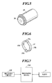
- a gear 36 is provided on the end face of the output shaft 34 as shown in FIG. 5 .
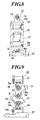
- the gear 32j and the gear 35 are joined via a clutch member 37 which is shown in FIG. 6 .
- a battery (omitted from the drawing), a processing device 100, and a receiving circuit 110 are installed in the body unit of the robot toy 1 (see FIG. 7 ).
- the processing device 100 is connected to the receiving circuit 110 and the servo motor 31.
- the processing device 100 processes the signals and the like from the receiving circuit 110 and the servo 3, and controls the operation of the servo motor 31. For example, when the power of the robot toy 1 is turned on, the processing device 100 applies the initial pulse to the servo motor 31 and moves the servo 3 to the center position (servo zero position).
- the robot toy 1 comprises a body unit 10, a head unit 11, leg units 12, and hand and arm units 13.
- the servo 3 is installed in each joining unit of the robot toy 1.
- the block 22 is joined to the block 21. That is, the servo 3b (a reference numeral 3b is used to discriminate the servo 3b from other servos) is installed in the block 21.
- the shaft hole at the joining unit of the block 22 fits to the output shaft 34 of the servo 3b, and thereby the block 22 is joined to the block 21. Therefore, when the servo motor 31 of the servo 3b is rotationally driven, the block 22 operates with respect to the block 21.
- the joining structure of the output shaft 34 and the block 22 in the above described case is same as the joining structure of the output shaft 34 of the servo 3c which is installed in the body unit 10 and the block 21. That is, the slot 50b is formed at the joining unit of the block 22, and the space of the slot 50b is adjustable by a screw.
- the joining unit is constructed so that the diameter of the shaft hole 50a of the block 22 can be changed so as to be in the play fit condition or the tight fit condition with respect to the output shaft 34 of the servo 3c by adjusting the space of the slot 50b.
- the joining structure of the output shaft 34 and the block 24 in the above described case is same as the joining structure of the output shaft 34 of the servo 3d which is installed in the body unit 10 and the block 21. That is, the slot 50b is formed at the joining unit of the block 24, and the space of the slot 50b is adjustable by a screw.
- the joining unit is constructed so that the diameter of the shaft hole 50a of the block 24 can be changed so as to be in the play fit condition or the tight fit condition with respect to the output shaft 34 of the servo 3d by adjusting the space of the slot 50b.
- the joining structure of the output shaft 34 and the block 25 in the above described case is same as the joining structure of the output shaft 34 of the servo 3e which is installed in the body unit 10 and the block 21. That is, the slot 50b is formed at the joining unit of the block 25, and the space of the slot 50b is adjustable by a screw.
- the joining unit is structured so that the diameter of the shaft hole 50a of the block 25 can be changed so as to be in the play fit condition or the tight fit condition with respect to the output shaft 34 of the servo 3e by adjusting the space of the slot 50b.
- the present invention is described above. However, the present invention is not limited to the embodiment, and can be variously modified within the gist of the invention.
- the position adjustment jig is a fit-in type, and the positional relationship of the blocks may be automatically adjusted to match with the home position of the robot toy 1 itself when the robot toy 1 is set.
Abstract
Description
- The present invention relates to a robot toy and an assembling method thereof, and more particularly, to a robot toy providing a servo and an assembling method thereof.
- Conventionally, there is known a robot toy having a structure in which one block and another block are joined via a servo. The robot toy is generally assembled in the following manner.
- First, a description will be given regarding a leg of the humanoid robot toy. Here, one block in which an RC turbo is installed and the other block which is to be joined thereto are included as components of the leg. In this case, first, a center position (servo zero position) is provided by applying an initial pulse to the signal wire of the servo, and a shaft hole which is formed on the other block is fitted to an output shaft of the servo at the position where the joining unit of the one block and the other block is extended (mechanical zero position). In such way, the adjacent blocks are assembled. Accordingly, the entire leg is assembled.
- Further, the components of hand and arm, a body unit and a head unit, and the body unit and the limbs are joined in the same manner as in the case of the leg.
- Here, "mechanical zero position" is a position of each component when the robot toy is in a basic posture. In general, an upright posture is the basic posture in the case of the robot toy walking with two legs (for example, see "Nisokuhoko robotto seisaku chonyuumon". Kabushikigaisha Ohmsha. 2006, October 5. Third impression of the first edition, pp.140-141).
- However, there are many cases where the mechanical zero position and the basic starting position (home position) of the robot toy are different. For example, regarding the robot toy walking with two legs, the upright posture position is the mechanical zero position, and a position in which the hip of the robot toy is slightly lowered is the home position. In the case of the robot toy walking with two legs, it is natural to walk by alternatively stepping out the left leg and the right leg forwardly from the position in which the hip of the robot toy is slightly lowered (home position).
- Further, as described above, the legs of the robot toy will first take the upright posture position when the initial pulse is applied to the signal wire of the servo because the servo zero position matches with the mechanical zero position. Subsequently, the robot toy slightly lowers the hip, and then, walks by alternatively stepping out the left leg and the right leg forwardly.
- Such a movement of the robot toy is unnatural.
- Consequently, there is a need for matching the servo zero position with the basic starting position. For example, in the case of the robot toy walking with two legs, there is a need for an adjustment so that the robot toy immediately takes the posture position in which the hip of the robot toy is slightly lowered (basic starting position; home position) when the initial pulse is applied to the signal wire of the servo.
- Therefore, conventionally, the servo zero position and the home position were adjusted to match with one another by connecting an IC for control inside the robot toy to a personal computer and changing the pulse width of the initial pulse by an editor.
- However, such an operation is complicated.
- Such a matter also occurs in a case where there are designing errors in the components of the robot toy.
- The present invention is to solve the above problem, and an object is to provide a robot toy which can easily match the home position with the servo zero position of the robot toy and an assembling method thereof.
- In accordance with a first aspect of the present invention, a robot toy comprises one block to which a servo is installed, another block joined to the one block by fitting an output shaft of the servo to a shaft hole, and a shaft hole diameter adjustment member to change a diameter of the shaft hole so as to be in a condition where the shaft hole is loosely fitted to the output shaft or a condition where the shaft hole is tightly fitted to the output shaft.
- Preferably, the robot toy further comprises a position adjustment jig to match a positional relationship between the one block and the another block with a home position when the another block is joined to the one block.
- Preferably, a slot communicating with the shaft hole of the another block is provided, and the shaft hole diameter adjustment member is a space adjustment member to change the diameter of the shaft hole so as to be in the condition where the shaft hole is loosely fitted to the output shaft or the condition where the shaft hole is tightly fitted to the output shaft by adjusting a space of the slot.
- In accordance with a second aspect of the present invention, an assembling method of the robot toy comprises fitting the shaft hole loosely to the output shaft, providing a center position of the servo in the condition where the shaft hole is loosely fitted to the output shaft, matching a positional relationship between the one block and the another block with a home position by a position adjustment jig in the condition where the shaft hole is loosely fitted to the output shaft, and fitting the shaft hole to the output shaft by adjusting the diameter of the shaft hole with the shaft hole diameter adjustment member.
- According to the present invention, the one block and the other block can be easily joined in the state where the robot toy is in the servo zero position.
- The above and other aspects of the present invention will become fully understood from the detailed description given hereinafter and the accompanying drawings, which are given by way of illustration only and thus are not intended as a definition of the limits of the present invention, wherein:
-
FIG. 1 is a front view of an embodiment of a robot toy according to the embodiment; -
FIG. 2 is a right side view of the robot toy ofFigure 1 ; -
FIG. 3 is a sectional view showing an example of a servo according to the embodiment ofFigure 1 ; -
FIG. 4 is a perspective view of one gear in a decelerating gear mechanism which composes a servo according to the embodiment ofFigure 1 ; -
FIG. 5 is a perspective view of an output shaft of a servo according to the embodiment ofFigure 1 ; -
FIG. 6 is a perspective view of a clutch member of a servo according to the embodiment ofFigure 1 ; -
FIG. 7 is a control block diagram according to the embodiment ofFigure 1 ; -
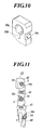
FIG. 8 is a front view of a leg unit of a robot toy according to the embodiment ofFigure 1 ; -
FIG. 9 is a right side view of a leg unit of a robot toy according to the embodiment ofFigure 1 ; -
FIG. 10 is a perspective view of a joining unit of blocks of a robot toy according to the embodiment ofFigure 1 ; -
FIG. 11 is a front view of a hand and arm unit of a robot toy according to the embodiment ofFigure 1 ; -
FIG. 12 is a right side view of a hand and arm unit of a robot toy according to the embodiment ofFigure 1 ; and -
FIG. 13 is a diagram showing an example of a position adjustment jig. -
FIG. 1 is a front view of a robot body, andFIG. 2 is a right side view of the robot body. The movement of arobot toy 1 is remotely controlled by the operation of a controller which is omitted from the drawings. Particularly, therobot toy 1 is constructed so that the movements of limbs of therobot toy 1 are controlled by the operation of the controller. - A
servo 3 shown inFIG. 3 is installed in the joining units of the limbs of therobot toy 1. Theservo 3 comprises aservo motor 31 which is housed in acase 30, a deceleratinggear mechanism 32, and arotary encoder 33. The deceleratinggear mechanism 32 is constructed by includinggears 32a to 32j. - Further, a
clutch mechanism 35 is installed between thelast gear 32j of thedecelerating gear mechanism 32 and theoutput shaft 34. - That is, the
gear 32j and theoutput shaft 34 are constructed so as to rotate independently from one another. Among thegears 32a to 32j, two half-column shapedprotrusions 32j-1, 32j-1 are provided on the end face of thegear 32j as shown inFIG. 4 . On the other hand, agear 36 is provided on the end face of theoutput shaft 34 as shown inFIG. 5 . Thegear 32j and thegear 35 are joined via aclutch member 37 which is shown inFIG. 6 . Theclutch member 37 is in a ring shape, and twoconcaved units protrusions 32j-1, 32j-1 and two convexedunits gear 36 are formed on the inner periphery of theclutch member 37. When theoutput shaft 34 is forcibly stopped due to some kinds of causes while the shaft of aservo motor 31 is rotating, theclutch member 37 elastically deforms and the power transmission to thegear 36 and therefore to theoutput shaft 34 from thegear 32j is blocked. - Moreover, a battery (omitted from the drawing), a processing device 100, and a
receiving circuit 110 are installed in the body unit of the robot toy 1 (seeFIG. 7 ). The processing device 100 is connected to thereceiving circuit 110 and theservo motor 31. In compliance with the program stored in the inner storage device, the processing device 100 processes the signals and the like from thereceiving circuit 110 and theservo 3, and controls the operation of theservo motor 31. For example, when the power of therobot toy 1 is turned on, the processing device 100 applies the initial pulse to theservo motor 31 and moves theservo 3 to the center position (servo zero position). - Subsequently, an outer structure of the
robot toy 1 is described. Therobot toy 1 comprises abody unit 10, ahead unit 11,leg units 12, and hand andarm units 13. The servo 3 is installed in each joining unit of therobot toy 1. - Here, the construction of the
leg unit 12 is described. Theleg unit 12 of therobot toy 1 comprises fiveblocks FIG. 8 (front view) andFIG. 9 (right side view). - Among these blocks, the
block 21 is joined to the body unit (block) 10. That is, theservo 3a (areference numeral 3a is used to discriminate theservo 3a from other servos) is installed in thebody unit 10. Further, theblock 21 fits to theoutput shaft 34 of theservo 3a, and thereby theblock 21 is joined to thebody unit 10. Therefore, when theservo motor 31 of theservo 3a is rotationally driven, theblock 21 operates with respect to thebody unit 10. - The joining structure of the
block 21 and thebody unit 10 is described in the above described case in detail. A slot (slit) 50b which reaches theshaft hole 50a is formed at the joining unit of theblock 21 as shown inFIG. 10 . The space of theslot 50b is constructed so as to be adjustable by ascrew 50c. Further, the joining unit is constructed so that the diameter of theshaft hole 50a can be changed by adjusting the space of theslot 50b according to the fastening level of thescrew 50c. In such case, thescrew 50c composes a space adjustment member and therefore a shaft hole diameter adjustment member. As the shaft hole diameter adjustment member, a clamp or a clip which holds the parts facing each other across theslot 50b from outside can be considered other than a mere screw. The followings are in the same manner. - Particularly, when the
screw 50c is loosened, theshaft hole 50a is in a condition where it is loosely fitted (play fit condition) to theoutput shaft 34. In this condition, theoutput shaft 34 is not integrated with theblock 21, and theoutput shaft 34 can run idle in theshaft hole 50a. On the other hand, when thescrew 50c is tightened, theshaft hole 50a is in a condition where it is tightly fitted (tight fit condition) to theoutput shaft 34. In such condition, theoutput shaft 34 is integrated with theblock 21 and theblock 21 rotates centering on theoutput shaft 34 when theoutput shaft 34 rotates. - Moreover, the
block 22 is joined to theblock 21. That is, theservo 3b (areference numeral 3b is used to discriminate theservo 3b from other servos) is installed in theblock 21. The shaft hole at the joining unit of theblock 22 fits to theoutput shaft 34 of theservo 3b, and thereby theblock 22 is joined to theblock 21. Therefore, when theservo motor 31 of theservo 3b is rotationally driven, theblock 22 operates with respect to theblock 21. - The joining structure of the
output shaft 34 and theblock 22 in the above described case is the same as the joining structure of theoutput shaft 34 of theservo 3b which is installed in thebody unit 10 and theblock 21. That is, theslot 50b is formed at the joining unit of theblock 22, and the space of theslot 50b is adjustable by a screw. The joining unit is constructed so that the diameter of theshaft hole 50a of theblock 22 can be changed so as to be in the play fit condition or the tight fit condition with respect to theoutput shaft 34 of theservo 3b by adjusting the space of theslot 50b. - Further, the
block 23 is joined to theblock 22. That is, theservo 3c (areference numeral 3c is used to discriminate theservo 3c from other servos) is installed in theblock 23. Theblock 22 fits to theoutput shaft 34 of theservo 3c, and thereby theblock 23 is joined to theblock 22. Therefore, when theservo motor 31 of theservo 3c is rotationally driven, theblock 23 operates with respect to theblock 22. - The joining structure of the
output shaft 34 and theblock 22 in the above described case is same as the joining structure of theoutput shaft 34 of theservo 3c which is installed in thebody unit 10 and theblock 21. That is, theslot 50b is formed at the joining unit of theblock 22, and the space of theslot 50b is adjustable by a screw. The joining unit is constructed so that the diameter of theshaft hole 50a of theblock 22 can be changed so as to be in the play fit condition or the tight fit condition with respect to theoutput shaft 34 of theservo 3c by adjusting the space of theslot 50b. - Further, the
block 24 is joined to theblock 23. That is, theservo 3d (areference numeral 3d is used to discriminate theservo 3d from other servos) is installed in theblock 23. Theblock 24 fits to theoutput shaft 34 of theservo 3d, and thereby theblock 24 is joined to theblock 23. Therefore, when theservo motor 31 of theservo 3d is rotationally driven, theblock 24 operates with respect to theblock 23. - The joining structure of the
output shaft 34 and theblock 24 in the above described case is same as the joining structure of theoutput shaft 34 of theservo 3d which is installed in thebody unit 10 and theblock 21. That is, theslot 50b is formed at the joining unit of theblock 24, and the space of theslot 50b is adjustable by a screw. The joining unit is constructed so that the diameter of theshaft hole 50a of theblock 24 can be changed so as to be in the play fit condition or the tight fit condition with respect to theoutput shaft 34 of theservo 3d by adjusting the space of theslot 50b. - Further, the
block 25 is joined to theblock 24. That is, the servo 3e (areference numeral 3e is used to discriminate theservo 3e from other servos) is installed in theblock 24. Theblock 25 fits to theoutput shaft 34 of theservo 3e, and thereby theblock 25 is linked to theblock 24. Therefore, when theservo motor 31 of theservo 3e is rotationally driven, theblock 25 operates with respect to theblock 24. - The joining structure of the
output shaft 34 and theblock 25 in the above described case is same as the joining structure of theoutput shaft 34 of theservo 3e which is installed in thebody unit 10 and theblock 21. That is, theslot 50b is formed at the joining unit of theblock 25, and the space of theslot 50b is adjustable by a screw. The joining unit is structured so that the diameter of theshaft hole 50a of theblock 25 can be changed so as to be in the play fit condition or the tight fit condition with respect to theoutput shaft 34 of theservo 3e by adjusting the space of theslot 50b. - Subsequently, the structure of the hand and
arm unit 13 is described. The hand andarm unit 13 comprises fiveblocks FIG. 11 (front view) andFIG. 12 (right side view). Theblocks leg unit 12. Here, the joining structure of the body unit (block) 10 and theblock 41 may be the same as the joining structure of the blocks of the hand andarm unit 13, or theblock 41 may be fixed to thebody unit 10. - Next, an assembling method of the
robot toy 1 will be described with theleg unit 12 as an example. - For example, in the case where the
body unit 10 and theblock 21 are being joined to one another, thescrew 50c is loosened and theshaft hole 50a of theblock 21 is loosely fitted to theoutput shaft 34 of theservo 3 which is installed in thebody unit 10. In such condition, theoutput shaft 34 is not integrated with theblock 21, and theoutput shaft 34 can run idle in theshaft hole 50a. The angle between thebody unit 10 and theblock 21 is adjusted by using a position adjustment jig in the above described condition. Particularly, the angle between thebody unit 10 and theblock 21 is adjusted to match with the home position. While maintaining the above described condition, theservo 3 is energized and thescrew 50c is tightened after the center position (servo zero position) of theservo 3 is provided. In such way, the servo zero position and the home position of thebody unit 10 and theblock 21 can be matched with one another. - In the same manner as described above, the adjacent blocks of the
leg unit 12 are joined to one another, and the adjacent blocks of the hand andarm unit 13 are joined to one another. - The embodiment of the present invention is described above. However, the present invention is not limited to the embodiment, and can be variously modified within the gist of the invention.
- For example, in the above embodiment, a description is given for the case where the blocks are joined one by one in order. However, for example, the positional relationship between the adjacent blocks of the
leg unit 12 can be adjusted to match with the home position of therobot toy 1 itself by the position adjustment jig, and theoutput shaft 34 and theshaft hole 50a may be adjusted to be in the tight fit condition by the space adjustment member in a state where theservo 3 is at the center position after the power of therobot toy 1 is turned on while pushing the reset button in a condition where the entire construction blocks of theleg unit 12 are loosely joined to one another (the condition where theshaft 34 of theservo 3 and theshaft hole 50a are loosely fitted to one another). - An example of the
position adjustment jig 60 which is used in the above described case is shown inFIG. 12 . InFIG. 12 , thereference numeral 60a is an indicator showing the position which corresponds to theoutput shaft 34 of theservo 3. When theoutput shaft 34 of theservo 3 is adjusted to match with theindicator 60a, the positional relationship between the blocks can be automatically adjusted to match with the home position of therobot toy 1 itself. - Here, the position adjustment jig is a fit-in type, and the positional relationship of the blocks may be automatically adjusted to match with the home position of the
robot toy 1 itself when therobot toy 1 is set. - The entire disclosures of Japanese Patent Application No.
2006-352818 filed on December 27, 2006
Claims (1)
- A robot toy (1), comprising:a first block;a second block; anda servo (3) installed at a joint portion of the first block and second block, the servo comprising a servo motor (31), a decelerating gear mechanism (32), a rotary encoder (33) and a clutch mechanism (35) which are housed in a case, whereina last gear (32j) of the decelerating gear mechanism (32) and an output shaft (34) of the servo (3) in which a shaft center matches with a shaft center of the last gear are structured so as to rotate independently, andthe clutch mechanism (35) installed between the last gear (32j) and the output shaft (34), comprises:a gear (36) provided at the output shaft (34);a half-column shaped protrusion (32j-1) in which an outside surface thereof is curved and which is provided so as to stand at a position separating from a shaft of an end face of the last gear (32j); anda ring shaped clutch member (37) which is elastically deformable and which has a concaved unit (37a) which engages with the half-column shaped protrusion (32j-1) and a convexed unit (37b) which engages with teeth of the gear (36) provided at the output shaft (34) formed at an inner periphery.
Applications Claiming Priority (2)
| Application Number | Priority Date | Filing Date | Title |
|---|---|---|---|
| JP2006352818A JP4551893B2 (en) | 2006-12-27 | 2006-12-27 | Robot toy |
| EP07122348A EP1938877B1 (en) | 2006-12-27 | 2007-12-05 | Robot toy and assembling method thereof |
Related Parent Applications (1)
| Application Number | Title | Priority Date | Filing Date |
|---|---|---|---|
| EP07122348.1 Division | 2007-12-05 |
Publications (3)
| Publication Number | Publication Date |
|---|---|
| EP2196248A2 true EP2196248A2 (en) | 2010-06-16 |
| EP2196248A3 EP2196248A3 (en) | 2011-03-16 |
| EP2196248B1 EP2196248B1 (en) | 2012-04-04 |
Family
ID=39292819
Family Applications (2)
| Application Number | Title | Priority Date | Filing Date |
|---|---|---|---|
| EP10156604A Expired - Fee Related EP2196248B1 (en) | 2006-12-27 | 2007-12-05 | Robot toy and assembling method thereof |
| EP07122348A Expired - Fee Related EP1938877B1 (en) | 2006-12-27 | 2007-12-05 | Robot toy and assembling method thereof |
Family Applications After (1)
| Application Number | Title | Priority Date | Filing Date |
|---|---|---|---|
| EP07122348A Expired - Fee Related EP1938877B1 (en) | 2006-12-27 | 2007-12-05 | Robot toy and assembling method thereof |
Country Status (6)
| Country | Link |
|---|---|
| US (1) | US7862398B2 (en) |
| EP (2) | EP2196248B1 (en) |
| JP (1) | JP4551893B2 (en) |
| KR (1) | KR20080061277A (en) |
| CN (1) | CN101209383A (en) |
| DE (1) | DE602007007718D1 (en) |
Families Citing this family (20)
| Publication number | Priority date | Publication date | Assignee | Title |
|---|---|---|---|---|
| JP4551893B2 (en) | 2006-12-27 | 2010-09-29 | 株式会社タカラトミー | Robot toy |
| JP4397412B2 (en) | 2007-12-07 | 2010-01-13 | 株式会社タカラトミー | Robot toy and its assembly method |
| CN203620240U (en) * | 2012-01-31 | 2014-06-04 | 株式会社多美 | Robot toy |
| CN103252093B (en) * | 2012-06-21 | 2015-04-29 | 上海未来伙伴机器人有限公司 | Steering engine component |
| US10695686B2 (en) * | 2013-09-27 | 2020-06-30 | Innovation First, Inc. | Mechanical spinning robot toy |
| JP6039702B2 (en) * | 2014-03-31 | 2016-12-07 | 株式会社アーテック | Assembly block with servo motor and assembly block kit |
| US9618937B1 (en) | 2014-08-25 | 2017-04-11 | Google Inc. | Slip detection using robotic limbs |
| US10081098B1 (en) | 2014-08-25 | 2018-09-25 | Boston Dynamics, Inc. | Generalized coordinate surrogates for integrated estimation and control |
| US9387588B1 (en) | 2014-08-25 | 2016-07-12 | Google Inc. | Handling gait disturbances with asynchronous timing |
| US9446518B1 (en) * | 2014-11-11 | 2016-09-20 | Google Inc. | Leg collision avoidance in a robotic device |
| US9499218B1 (en) | 2014-12-30 | 2016-11-22 | Google Inc. | Mechanically-timed footsteps for a robotic device |
| US9594377B1 (en) * | 2015-05-12 | 2017-03-14 | Google Inc. | Auto-height swing adjustment |
| US10317872B2 (en) * | 2015-08-07 | 2019-06-11 | Spm Automation (Canada) Inc. | Method of self-adjusting a machine to compensate for part-to-part variations |
| US9586316B1 (en) | 2015-09-15 | 2017-03-07 | Google Inc. | Determination of robotic step path |
| US9789919B1 (en) | 2016-03-22 | 2017-10-17 | Google Inc. | Mitigating sensor noise in legged robots |
| USD835214S1 (en) * | 2017-06-13 | 2018-12-04 | Ubtech Education (Shenzhen) Co., Ltd | Robot |
| USD832373S1 (en) * | 2017-10-06 | 2018-10-30 | Kma Concepts Limited | Posable toy gorilla |
| CN107791242A (en) * | 2017-11-23 | 2018-03-13 | 深圳市优必选科技有限公司 | Steering wheel and robot |
| KR20210143461A (en) * | 2020-05-20 | 2021-11-29 | 로보티즈 인코포레이티드 | Small actuator for robot |
| CN117018639A (en) * | 2023-08-18 | 2023-11-10 | 蔡泽銮 | Assembling robot toy |
Citations (1)
| Publication number | Priority date | Publication date | Assignee | Title |
|---|---|---|---|---|
| US6032548A (en) | 1997-08-08 | 2000-03-07 | Del Castillo; Leonardo | System and method for creating movement utilizing a servo mechanism with a self-aligning clutch |
Family Cites Families (26)
| Publication number | Priority date | Publication date | Assignee | Title |
|---|---|---|---|---|
| US3547240A (en) * | 1968-09-19 | 1970-12-15 | Frank Holper | Clutch means for selectively coupling a single input to one or more plural outputs |
| US5155423A (en) * | 1986-02-18 | 1992-10-13 | Robotics Research Corporation | Industrial robot with servo |
| JP2602815B2 (en) * | 1986-08-08 | 1997-04-23 | 株式会社東芝 | Joint device |
| JPH061193Y2 (en) * | 1987-09-14 | 1994-01-12 | 精工研株式会社 | Bidirectional clutch for mainspring power unit |
| JPH0377754A (en) | 1989-08-18 | 1991-04-03 | Kawasaki Steel Corp | Method for preventing drift stream of molten steel poured into continuous casting mold |
| US5280981A (en) * | 1991-02-01 | 1994-01-25 | Odetics, Inc. | End effector with load-sensitive digit actuation mechanisms |
| US5158493A (en) * | 1991-05-30 | 1992-10-27 | Richard Morgrey | Remote controlled, multi-legged, walking robot |
| US5318471A (en) * | 1991-12-06 | 1994-06-07 | Glovier Lloyd H | Robotic joint movement device |
| JPH09193059A (en) | 1996-01-17 | 1997-07-29 | Canon Inc | Origin position calibrating method of robot, its origin position calibrating device, calibrating jig and arm positioning device of robot |
| US5823845A (en) * | 1996-03-12 | 1998-10-20 | Kieran Bergin, Inc. | Mobile, gyroscopically stabilized toy with controlled multi-action movements |
| KR100639900B1 (en) * | 1999-01-28 | 2006-10-31 | 소니 가부시끼 가이샤 | Joint device for robot device and leg-walking robot device |
| US6902048B1 (en) * | 1999-04-14 | 2005-06-07 | Caleb Chung | Clutch |
| JP2002059388A (en) * | 2000-08-23 | 2002-02-26 | Sony Corp | Rotary actuator and walking robot with rotary actuator |
| JP3854926B2 (en) | 2000-11-17 | 2006-12-06 | 本田技研工業株式会社 | Legged walking robot |
| US6454624B1 (en) * | 2001-08-24 | 2002-09-24 | Xerox Corporation | Robotic toy with posable joints |
| JP3757147B2 (en) * | 2001-10-31 | 2006-03-22 | オムロン株式会社 | Robot joint structure |
| JP3558220B2 (en) * | 2002-03-18 | 2004-08-25 | ソニー株式会社 | Hand device and robot device used for robot device |
| US6989645B2 (en) * | 2002-12-18 | 2006-01-24 | Sony Corporation | Robot apparatus, and load absorbing apparatus and method |
| KR100578342B1 (en) * | 2003-01-03 | 2006-05-11 | 주식회사 메가로보틱스 | Method control for and robot toy type artificial intelligence |
| JP2004255475A (en) | 2003-02-24 | 2004-09-16 | Oki Electric Ind Co Ltd | Servo apparatus |
| JP4299567B2 (en) * | 2003-03-31 | 2009-07-22 | 本田技研工業株式会社 | Legged mobile robot |
| JP2006035405A (en) * | 2004-07-30 | 2006-02-09 | Sanko Gosei Ltd | Joint device for robot |
| JP4305323B2 (en) * | 2004-08-11 | 2009-07-29 | ソニー株式会社 | Robot apparatus motion control device and motion control method |
| JP4506512B2 (en) | 2005-03-07 | 2010-07-21 | トヨタ自動車株式会社 | Offset adjustment system and offset adjustment method for walking robot with supporting legs |
| JP4254804B2 (en) * | 2006-05-15 | 2009-04-15 | 双葉電子工業株式会社 | Coupling mechanism of connecting member for robot and walking robot |
| JP4551893B2 (en) | 2006-12-27 | 2010-09-29 | 株式会社タカラトミー | Robot toy |
-
2006
- 2006-12-27 JP JP2006352818A patent/JP4551893B2/en not_active Expired - Fee Related
-
2007
- 2007-07-03 US US11/822,300 patent/US7862398B2/en not_active Expired - Fee Related
- 2007-12-05 EP EP10156604A patent/EP2196248B1/en not_active Expired - Fee Related
- 2007-12-05 EP EP07122348A patent/EP1938877B1/en not_active Expired - Fee Related
- 2007-12-05 DE DE602007007718T patent/DE602007007718D1/en active Active
- 2007-12-12 KR KR1020070128782A patent/KR20080061277A/en not_active Application Discontinuation
- 2007-12-27 CN CNA2007101608654A patent/CN101209383A/en active Pending
Patent Citations (1)
| Publication number | Priority date | Publication date | Assignee | Title |
|---|---|---|---|---|
| US6032548A (en) | 1997-08-08 | 2000-03-07 | Del Castillo; Leonardo | System and method for creating movement utilizing a servo mechanism with a self-aligning clutch |
Also Published As
| Publication number | Publication date |
|---|---|
| EP1938877B1 (en) | 2010-07-14 |
| DE602007007718D1 (en) | 2010-08-26 |
| US7862398B2 (en) | 2011-01-04 |
| EP2196248B1 (en) | 2012-04-04 |
| JP4551893B2 (en) | 2010-09-29 |
| EP1938877A1 (en) | 2008-07-02 |
| JP2008161350A (en) | 2008-07-17 |
| CN101209383A (en) | 2008-07-02 |
| US20080160873A1 (en) | 2008-07-03 |
| EP2196248A3 (en) | 2011-03-16 |
| KR20080061277A (en) | 2008-07-02 |
Similar Documents
| Publication | Publication Date | Title |
|---|---|---|
| EP1938877B1 (en) | Robot toy and assembling method thereof | |
| JP4254804B2 (en) | Coupling mechanism of connecting member for robot and walking robot | |
| US6454624B1 (en) | Robotic toy with posable joints | |
| US6575802B2 (en) | Robotic toy modular system with distributed program | |
| JP5972346B2 (en) | Robot apparatus, robot control method, program, and recording medium | |
| EP2599590A1 (en) | Tangless helical coil insert inserting tool | |
| EP2068219A2 (en) | Robot toy and assembling method thereof | |
| EP2108418A1 (en) | Joint structure of toy | |
| KR100639900B1 (en) | Joint device for robot device and leg-walking robot device | |
| JP2003145476A (en) | Robot hinge device | |
| CN107309907B (en) | Robot joint limit structure and robot | |
| KR910003624B1 (en) | Operating change-over apparatus of active toy and active toy using the same | |
| US8819940B2 (en) | Method for manufacturing a linear actuator | |
| KR20220077848A (en) | Apparatus for feedind insert | |
| US20030047017A1 (en) | Gear structure for a figurine | |
| KR101399096B1 (en) | Method for setting zero-point of modular robot and the modular robot thereof | |
| JP4278015B2 (en) | Gear head mounting mechanism | |
| AU7214500A (en) | Gear drive for an electric motor | |
| JP2001138144A5 (en) | ||
| JP2000280195A (en) | Joint device, leg type traveling device and arm device for robot device, leg type traveling robot device, and driving force transmitting device | |
| JP2005297080A (en) | Robot device and joint device of robot | |
| KR0183689B1 (en) | Method and apparatus to decide origin point | |
| JP2003002241A (en) | Cowl top for vehicle, and its attaching method | |
| Bessent | Structure Climbing Monkey Robot | |
| JPH0677786U (en) | Ball device for pachinko machines |
Legal Events
| Date | Code | Title | Description |
|---|---|---|---|
| PUAI | Public reference made under article 153(3) epc to a published international application that has entered the european phase |
Free format text: ORIGINAL CODE: 0009012 |
|
| AC | Divisional application: reference to earlier application |
Ref document number: 1938877 Country of ref document: EP Kind code of ref document: P |
|
| AK | Designated contracting states |
Kind code of ref document: A2 Designated state(s): DE FR GB |
|
| PUAL | Search report despatched |
Free format text: ORIGINAL CODE: 0009013 |
|
| AK | Designated contracting states |
Kind code of ref document: A3 Designated state(s): DE FR GB |
|
| GRAP | Despatch of communication of intention to grant a patent |
Free format text: ORIGINAL CODE: EPIDOSNIGR1 |
|
| 17P | Request for examination filed |
Effective date: 20110909 |
|
| RIC1 | Information provided on ipc code assigned before grant |
Ipc: B25J 9/08 20060101ALI20110929BHEP Ipc: A63H 30/04 20060101ALN20110929BHEP Ipc: B62D 57/032 20060101ALI20110929BHEP Ipc: A63H 11/18 20060101AFI20110929BHEP Ipc: B62D 57/00 20060101ALI20110929BHEP |
|
| GRAS | Grant fee paid |
Free format text: ORIGINAL CODE: EPIDOSNIGR3 |
|
| GRAA | (expected) grant |
Free format text: ORIGINAL CODE: 0009210 |
|
| AC | Divisional application: reference to earlier application |
Ref document number: 1938877 Country of ref document: EP Kind code of ref document: P |
|
| AK | Designated contracting states |
Kind code of ref document: B1 Designated state(s): DE FR GB |
|
| REG | Reference to a national code |
Ref country code: GB Ref legal event code: FG4D |
|
| REG | Reference to a national code |
Ref country code: DE Ref legal event code: R096 Ref document number: 602007021810 Country of ref document: DE Effective date: 20120606 |
|
| PLBE | No opposition filed within time limit |
Free format text: ORIGINAL CODE: 0009261 |
|
| STAA | Information on the status of an ep patent application or granted ep patent |
Free format text: STATUS: NO OPPOSITION FILED WITHIN TIME LIMIT |
|
| 26N | No opposition filed |
Effective date: 20130107 |
|
| REG | Reference to a national code |
Ref country code: DE Ref legal event code: R097 Ref document number: 602007021810 Country of ref document: DE Effective date: 20130107 |
|
| GBPC | Gb: european patent ceased through non-payment of renewal fee |
Effective date: 20121205 |
|
| REG | Reference to a national code |
Ref country code: FR Ref legal event code: ST Effective date: 20130830 |
|
| REG | Reference to a national code |
Ref country code: DE Ref legal event code: R119 Ref document number: 602007021810 Country of ref document: DE Effective date: 20130702 |
|
| PG25 | Lapsed in a contracting state [announced via postgrant information from national office to epo] |
Ref country code: DE Free format text: LAPSE BECAUSE OF NON-PAYMENT OF DUE FEES Effective date: 20130702 |
|
| PG25 | Lapsed in a contracting state [announced via postgrant information from national office to epo] |
Ref country code: FR Free format text: LAPSE BECAUSE OF NON-PAYMENT OF DUE FEES Effective date: 20130102 Ref country code: GB Free format text: LAPSE BECAUSE OF NON-PAYMENT OF DUE FEES Effective date: 20121205 |