EP2196845A1 - Method for preparing an ophthalmic lens in order to mount it on a curved spectacle frame - Google Patents
Method for preparing an ophthalmic lens in order to mount it on a curved spectacle frame Download PDFInfo
- Publication number
- EP2196845A1 EP2196845A1 EP09290889A EP09290889A EP2196845A1 EP 2196845 A1 EP2196845 A1 EP 2196845A1 EP 09290889 A EP09290889 A EP 09290889A EP 09290889 A EP09290889 A EP 09290889A EP 2196845 A1 EP2196845 A1 EP 2196845A1
- Authority
- EP
- European Patent Office
- Prior art keywords
- frame
- curve
- ophthalmic lens
- parameter
- circle
- Prior art date
- Legal status (The legal status is an assumption and is not a legal conclusion. Google has not performed a legal analysis and makes no representation as to the accuracy of the status listed.)
- Granted
Links
- 238000000034 method Methods 0.000 title abstract description 23
- 239000013598 vector Substances 0.000 claims description 35
- 239000011521 glass Substances 0.000 claims description 18
- 238000009966 trimming Methods 0.000 claims description 18
- 238000002360 preparation method Methods 0.000 claims description 17
- 230000000903 blocking effect Effects 0.000 claims description 11
- 238000004519 manufacturing process Methods 0.000 claims 1
- 230000003287 optical effect Effects 0.000 abstract description 30
- 238000006073 displacement reaction Methods 0.000 abstract 1
- 210000001747 pupil Anatomy 0.000 description 14
- 230000001179 pupillary effect Effects 0.000 description 13
- 238000003754 machining Methods 0.000 description 11
- 239000000523 sample Substances 0.000 description 8
- 238000004458 analytical method Methods 0.000 description 6
- 230000000694 effects Effects 0.000 description 6
- 238000012545 processing Methods 0.000 description 6
- 239000003550 marker Substances 0.000 description 5
- 230000037230 mobility Effects 0.000 description 4
- 238000012937 correction Methods 0.000 description 3
- 230000000750 progressive effect Effects 0.000 description 3
- 201000009310 astigmatism Diseases 0.000 description 2
- 210000000887 face Anatomy 0.000 description 2
- 238000005286 illumination Methods 0.000 description 2
- 230000007246 mechanism Effects 0.000 description 2
- 230000002123 temporal effect Effects 0.000 description 2
- 206010052143 Ocular discomfort Diseases 0.000 description 1
- 230000009471 action Effects 0.000 description 1
- 238000004891 communication Methods 0.000 description 1
- 230000000295 complement effect Effects 0.000 description 1
- 238000005520 cutting process Methods 0.000 description 1
- 238000000151 deposition Methods 0.000 description 1
- 238000001514 detection method Methods 0.000 description 1
- 238000010586 diagram Methods 0.000 description 1
- 238000005553 drilling Methods 0.000 description 1
- 230000004438 eyesight Effects 0.000 description 1
- 230000004907 flux Effects 0.000 description 1
- 238000005259 measurement Methods 0.000 description 1
- DJWYOLJPSHDSAL-ROUUACIJSA-N pantethine Chemical compound OCC(C)(C)[C@@H](O)C(=O)NCCC(=O)NCCSSCCNC(=O)CCNC(=O)[C@H](O)C(C)(C)CO DJWYOLJPSHDSAL-ROUUACIJSA-N 0.000 description 1
- 229960000903 pantethine Drugs 0.000 description 1
- 230000008569 process Effects 0.000 description 1
- 238000011160 research Methods 0.000 description 1
- 238000013519 translation Methods 0.000 description 1
- 238000012795 verification Methods 0.000 description 1
- 230000004304 visual acuity Effects 0.000 description 1
Images


Classifications
-
- G—PHYSICS
- G02—OPTICS
- G02C—SPECTACLES; SUNGLASSES OR GOGGLES INSOFAR AS THEY HAVE THE SAME FEATURES AS SPECTACLES; CONTACT LENSES
- G02C13/00—Assembling; Repairing; Cleaning
- G02C13/003—Measuring during assembly or fitting of spectacles
- G02C13/005—Measuring geometric parameters required to locate ophtalmic lenses in spectacles frames
Definitions
- the present invention relates generally to the field of eyewear and more specifically the mounting of ophthalmic lenses of a pair of corrective glasses on a frame.
- It relates more particularly to a method for preparing an ophthalmic lens for mounting in a circle of a spectacle frame.
- the invention finds a particularly advantageous application in the centering of ophthalmic lenses to be mounted on heavily curved eyeglass frames.
- This operation consists, initially, in positioning the final contour of the lens on the centering point of the lens, so that once centered, the wearer's line of sight passes through the centering point of the lens.
- This operation then consists, in a second step, in orienting the final contour of the lens around the centering point of the lens, so that once oriented, the reference axis of the lens (typically its cylinder axis or its axis of the horizontal) has a desired angle with respect to the horizon line of the frame.
- the reference axis of the lens typically its cylinder axis or its axis of the horizontal
- An object of the present invention is to provide a method of preparation to avoid or at least reduce the centering error and orientation of the ophthalmic lenses on the spectacle frame chosen by the wearer.
- the optical market is evolving and offers a growing number of highly curved frame frames, that is to say highly curved to wrap the wearer's face.
- the average plane of each circle is strongly inclined relative to the general plane of the frame.
- the Applicant has analyzed, as part of its research, that the centering errors stemmed from the fact that the acquisition of the position of the skyline of the frame was made in the general plane of the frame, whereas the orientation of the final contour of the lens was made in the plane of the lens, that is to say in the plane of the circle of the frame.
- the orientation of the final contour is then calculated according to a general parameter relative to the curvature of the frame, so as to cancel these centering errors.
- This general parameter is preferably a curve parameter, that is to say a parameter relating to the curve angle formed between the average plane of each circle and the general plane of the frame.
- This general parameter may also, alternatively, be a curve compensation parameter, that is to say a parameter relating to the angular correction to be made to the orientation of the final contour to compensate for the centering error due to the curve. of the mount.
- a curve compensation parameter that is to say a parameter relating to the angular correction to be made to the orientation of the final contour to compensate for the centering error due to the curve. of the mount.
- the objective of the preparation method according to the invention is to determine the position that two ophthalmic lenses 10, namely a left ophthalmic lens and a right ophthalmic lens, must occupy on a spectacle frame 20 in order to be properly centered with respect to each other. eye pupils of the wearer, so that they perform properly the optical functions for which they were designed.
- the preparation process used to center the left ophthalmic lens on the left circle 21 of the frame 20 will be described more precisely here.
- the implementation of the method finds a particularly advantageous application by the implementation of a program capable of performing the steps of the centering method described in a software integrated in a centering device or a blocking device or a trimming device provided with a processing unit and possibly a control screen.
- FIG 7 schematically shows an embodiment of a center-and-clamp device 100 which comprises a work console 101 on which is disposed a centering mechanism 102 of an ophthalmic lens 10.
- the centering and blocking device 100 further comprises a display screen 105 fixed on the frame 104 so as to be oriented to be visible to the user working on the work console 101.
- the centering mechanism 102 of the work console 101 here comprises a set of three jaws 114 with concentric clamping each carried by an arm 115 pivoting about an axis (not visible on the figure 7 )
- the arms are arranged so that their joint rotation about their respective axis allows the approximation of the three jaws 114.
- Clamping jaws 114 is controlled by a motor 117 whose axis is integral with a pinion 118 meshing on a ring 119 adapted to drive the arms 115 in rotation about their axis.
- the arms 115 in fact each comprise a semi-circular toothed portion (not shown) meshing with the outer periphery of the ring 119.
- a cell 120 optical or electromagnetic, allows the engine 117 to know the position of the crown 119.
- the assembly formed by the arms 115 carrying the jaws 114, and the ring 119 is disposed above a support plate 121 adapted to let the light.
- the centering-locking device comprises a positioning arm 106, preferably automated, connected to the frame 104, and adapted to take with the aid of a clamp a locking member disposed on a receptacle 107 and to come and deposit it at a location determined by calculation on the front face of said ophthalmic lens 10.
- the center-and-clamp device 100 is adapted to detect the position of a centering and / or axle mark of the ophthalmic lens 10.
- the reception means is constituted here by the support plate 121 transparent to light.
- the illumination means comprise a light source So which emits a diverging light beam 201 towards a deflection system comprising a mirror 126 inclined at 45 ° and a convergent lens 123 adapted to form a flux light ray 202 with parallel rays in the direction of the ophthalmic lens 10 deposited on the support plate 121 with its front face, provided with one or more centering and / or centering marks, facing said convergent lens 123.
- the acquisition and analysis means here comprise a digital camera Ca, image processing means (not shown) adapted to process the signal obtained at the output of the digital camera Ca and display means of the processed signal constituted by the display screen 105.
- Said acquisition and analysis means comprise between the transparent sign support 124 and the digital camera Ca an optical system for returning the light beam transmitted by the ophthalmic lens 10 comprising a frosted plate 122 forming screen and a mirror 125 inclined at 45 °.
- the digital camera Ca collects, via the optical angular return made by the inclined mirror 125, the images or shadows projected onto the frosted screen 122.
- the eyeglass frame 20 is of the rim type.
- this method will also be applicable to centering lenses on semi-rimmed (arcade) or pierced eyeglass frames.
- the optician Prior to the implementation of the centering method, the optician has the future wearer choose the shape of the frame 20 he desires. This choice is made among spectacle frames 20 that the optician possesses. Alternatively, this choice could also be made on a computer screen, by means of a database register storing a plurality of spectacle frame shapes.
- each eyeglass frame 20 comprises two circles 21 each intended to receive a right or left ophthalmic lens.
- These two circles 21 each comprise internally a longitudinal groove (called bezel) intended to fit on an interlocking rib (called bevel) running along the edge of the corresponding lens.
- the two circles 21 are connected to each other by a bridge or bridge 22 and are each provided with a branch 23.
- a substantially horizontal plane C2 corresponding to the plane passing through the two branches 23 of the frame 20 when they are in the unfolded position is defined relative to the frame 20.
- a vertical plane C3 corresponding to the plane of symmetry of the frame 20 is also defined.
- the general plane C1 of the frame 20 is also defined as the plane passing through the top of the bridge 22 of the frame 20 and which is orthogonal, firstly, at the vertical plane C3 of the frame 20, and secondly at the horizontal plane C2 of the frame 20.
- the average plane C4 of each circle 21 is defined as the plane which passes as close as possible to the all the points of the bottom of the bezel of this circle.
- the coordinates of this plane can for example be obtained by applying the least squares method to the coordinates of a plurality of points of the bottom of the bezel.
- the optician acquires the geometry of a longitudinal profile 30 corresponding to the bottom line of the bezel of the left circle 21 of the frame 20.
- a reading device contours such as for example that described in the patent US 5,802,731 .
- An example of such a device is that marketed by Essilor International under the trademark Kappa or Kappa CT.
- the optician blocks the eyeglass frame in the device, then starts the scanning sequence of the two circles of the spectacle frame 20.
- a probe follows, with or without contact, the bottom of the bezel of the first and the second circle, so as to identify a three-dimensional digital image of the first longitudinal profiles 30 of the two circles.
- probing with or without contact is meant probing by mechanical sliding of the probe along the bezel or by optical reading.
- the solution envisaged then consists in palpating separately each circle of the frame, by first inclining the frame so that the average plane of the circle to be probed is substantially perpendicular to the axis of rotation of the probe.
- This solution is effective since it reduces the inclination of the bezel seen by the probe in the temporal area of the circle, which prevents the probe from coming out of the bezel.
- two digital three-dimensional images are obtained on each of which the longitudinal profile 30 of one of the two circles of the frame 20 appears.
- the shape of the longitudinal profile 30 is stored in the processing unit of the centering device.
- This processing unit also stores the position of a horizon line 32 of the eyeglass frame 20 to allow the identification of the angular orientation of the longitudinal profile 30 relative to the horizontal.
- a boxing frame 33 defined relative to the longitudinal profile 30 a boxing frame 33 well known to those skilled in the art, which corresponds to the virtual rectangular frame circumscribed longitudinal profile 30.
- This boxing frame 33 is oriented relative to the longitudinal profile 30 of so that two of its edges are parallel to the horizon line 32. It has a length A and a height B.
- This frame 33 has an upper left corner Pn (bridge side 22), a top right corner Pn1 (branch side 23) , a lower left corner Pn2 and a lower right corner Pn3.
- the optician also acquires characteristic values of the overall shape of the frame chosen by the wearer.
- the angle of curve ⁇ curve corresponds to the angle formed, in the horizontal plane C2, between the mean plane C4 of the left circle 21 and the general plane C1 of the frame 20.
- the pantoscopic angle ⁇ panto corresponds to the angle formed, in the plane of symmetry C3, between the mean plane C4 of the left circle 21 and the general plane C1 of the frame 20.
- a first method consists, when the first two longitudinal profiles 30 appear on one and the same three-dimensional digital image, to compare the relative positions of these two first longitudinal profiles 30 so as to deduce the curve angle ⁇ curve .
- a second method consists of measuring or estimating these angle values, and manually entering them on a human-machine interface of the centering device.
- the optician can use a measuring chart.
- Such an abacus comprises for example two bundles of lines separated from each other by a length equal to that of the bridge. Each line of each beam has a determined inclination which corresponds to a particular curve angle of the frame.
- the user must position the spectacle frame on the screen, so that the two circles of the frame are superimposed on two of the lines of the abacus. In this way, by reading the relative inclination of these two lines, he can accurately determine the angle of curvature of the frame and store it in order to trim the lenses.
- the optician may use tools such as "mounting clips" which are elements to be fixed to the branches of the frames and which read, from the side, the inclination of circles in relation to the branches.
- a third method is to use a database register accessible to the optician or the centering device.
- a database register accessible to the optician or the centering device.
- Such a register comprises a plurality of records each associated with a type of glasses frames referenced.
- Each record then comprises an identifier of this type of frames, as well as the values of the curved ⁇ curve and pantoscopic angles ⁇ panto associated with this type of frames.
- the curvature and pantoscopic angle values of the spectacle frame 20 selected by the wearer are then acquired by searching the register for a record corresponding to this eyeglass frame, and, if such a corresponding record is found, by reading in this recording angles ⁇ curve curvature and pantoscopic ⁇ panto associated.
- the identifier may be constituted by the reference of the frame or by the name of the model of the frame.
- the optician then proceeds to locate the position of a pupil point Pc of the wearer relative to the longitudinal profile 30 ( figure 3 ).
- This pupillary point Pc corresponds to the point disposed opposite the pupil of the eye of the wearer, on the front face of the lens, when the wearer is wearing the eyeglass frame 20.
- the position of the pupillary point Pc is generally marked with respect to the boxing frame 33.
- the optician equips the wearer of the spectacle frame 20 that he has chosen, then he manually points on each of the presentation lenses delivered with the frame the pupillary point Pc corresponding to the point positioned next to the pupil of the wearer's eye.
- the optician To locate the position of the pupillary point Pc with respect to the boxing frame 33, the optician then measures with a ruler, in the general plane C1 of the frame 20, two parameters related to the morphology of the wearer. It acquires the interpupillary half-distance dPD defined as the distance horizontally separating the pupillary point Pc and the left edge of the boxing frame 33. It also acquires the pupillary height H of the wearer's left pupil by determining the distance vertically separating the point Pupillary Pc of the lower edge of the boxing frame 33. The knowledge of these two parameters and allows to locate the position of the longitudinal profile 30 relative to the pupillary point Pc.
- dPD interpupillary half-distance
- the optician could perform this operation using a pupillometer or a digital image acquisition and processing software as described in the documents US 5617155A and ES 2043546 , which realizes an identification of the pupil point Pc from a digital photo of the wearer's face equipped with his eyeglass frame.
- the optician also has an ophthalmic lens 10 not cut off, whose refractive properties correspond to the prescription of the wearer.
- This prescription corresponds to the correction to be made to each eye of the wearer so that he finds good visual acuity in close and / or far vision, depending on whether the lens is a unifocal, bi-focal or progressive addition lens. powers.
- the refractive properties of the lens are generally defined in terms of refractive powers. Only two of these refractive powers will be defined here, namely its spherical refractive power and its cylindrical refractive power.
- the "spherical refractive power" of a lens for an incident ray beam passing through this lens is defined as the magnitude that characterizes and quantifies the first effect of spherical refraction ("magnifying" effect) of the lens on the ray beam considered: if it is positive, the lens has a convergent effect on the ray beam; if it is negative, the effect on the beam of rays is divergent.
- the point of the lens where the magnifying effect is zero is called optical centering point.
- the "cylindrical refractive power" of a lens for an incident ray passing through this lens is itself defined as the magnitude that characterizes and quantifies the cylindrical refraction effect exerted by the lens on the beam. considered, according to which it is formed not one but two focal areas, located in different planes, generally perpendicular to each other and called focal tangential and sagittal focal.
- This cylindrical power also called “astigmatism power” or simply “astigmatism” corresponds to the difference of the spherical powers according to the two focal areas.
- the two areas are identified by an axis passing through their “optical centering point", commonly called cylinder axis. This cylinder axis is generally defined in degrees, relative to a line of registration of the lens.
- the ophthalmic lens 10 not cut off has an initial contour of known shape, generally circular, and an optical centering point P1 of known position.
- the ophthalmic lens 10 not cut off is spotted in space by its optical centering point P1 and by a registration line 11 for locating its orientation around its optical centering point P1.
- the detection of the position of the optical centering point P1 of the ophthalmic lens 10 can be carried out by various techniques, depending on the type of the ophthalmic lens and the equipment available to the optician.
- this technique can be deflectometric, interferometric or image processing. It will here preferably be implemented by means of the centraliser-blocker device 100 mentioned above.
- the device used will make it possible to determine the orientation of the cylinder axis of the lens relative to its registration line 11.
- the device used will determine the position of the markings engraved in the lens or printed on one of its faces, so as to determine the orientation of its axis called the horizontal.
- the processing software has thus acquired and memorized the optical reference system of the ophthalmic lens 10 defined by its centering point P1 and by its registration line 11.
- This reference frame is therefore defined in a reference plane, which is in the orthogonal species to an optical axis of the lens (axis which passes through the front and rear faces of the lens) and coincides with the average plane C4 of the circle 21 of the spectacle frame 20 (when the lens 10 is mounted on the spectacle frame 20).
- the processing software has also acquired and memorized, on the one hand, the reference frame of the circle 21 of the eyeglass frame 20 defined by the pupil point Pc and by the horizon line 32, and, on the other hand, part, the position and the orientation of the longitudinal profile 30 in the reference frame of the circle 21.
- the reference frame of the circle 21 is also defined in a reference plane of the eyeglass frame, which corresponds here to the general plane C1 of the frame 20.
- the next step is then to position and orient the longitudinal profile 30 in the optical reference of the ophthalmic lens 10, so as to determine which contour will be cut the lens.
- the processing software then proceeds to coincide the references of the ophthalmic lens 10 and the circle 21, so as to define the position and orientation of the longitudinal profile 30 no longer in the frame of reference of the circle, but directly in the frame of reference. ophthalmic lens optics 10.
- This coincidence is performed in two stages, including a step of superposition of the two reference frames ( figure 5 ), and a step of shifting the two reference frames to take into account that the measurements made in these two frames of reference were made in two reference planes C1, C4 inclined with respect to each other.
- the software virtually superimposes the two reference frames, so that the centering point P1 of the lens 10 is superimposed on the pupillary point Pc, and so that the registration line 11 is properly oriented relative to the line Horizon 32, according to a prescription of the future bearer of the spectacle frame.
- the registration line is "suitably oriented" when it is superimposed on the horizon line 32.
- the registration line will be "suitably oriented” when its orientation corresponds to the orientation of the axis of registration. cylinder or the axis of the horizontal prescribed to the carrier.
- the software controls the display of the longitudinal profile 30 on the display screen 105 of the centering-and-clamping device 100 ( figure 10 ).
- the references of the lens and the frame of the frame are marked in planes inclined relative to each other. More specifically, the plane of the optical lens of the repository is tilted horizontally to the plane of the reference circle 21 at an angle corresponding to the angle of curvature ⁇ contour and is inclined vertically relative to the plane of the reference circle 21 an angle corresponding to pantoscopic angle ⁇ panto .
- This inclination therefore produces a shift that must be taken into account to ensure optimal centering of the ophthalmic lens in the circle of the spectacle frame.
- the processing software shifts the pupillary point Pc with respect to the centering point P1 of an offset vector comprising a horizontal component dx and a vertical component dy. he angularly shifts the horizon line 32 relative to the registration line 11 of an offset angle d ⁇ .
- a second reference (O, Va, Vb, Vc) attached to the reference frame of the lens 10 is also considered.
- the origin O of this marker coincides with the origin of the first marker.
- the director vector Va corresponds to the transformant of the vector PnPn1 in the plane C4 of the marker of the lens 10, according to the rotations of ⁇ - curved and pantoscopic ⁇ - panto curve angles.
- the director vector Vb corresponds to the transformant of the vector PnPn2 in the plane C4 of the marker of the lens 10, according to the rotations of ⁇ - curved and pantoscopic ⁇ - panto curve angles.
- the director vector Vc is defined as the vector product of the first two leading vectors Va and Vb.
- V at ⁇ burp ⁇ panto ⁇ burp ⁇ curved ⁇ AT 0 0
- V b ⁇ burp ⁇ panto ⁇ burp ⁇ curved ⁇ 0 - B 0
- V ⁇ at AT ⁇ cos ⁇ curved AT ⁇ sin ⁇ curved ⁇ sin ⁇ panto AT ⁇ sin ⁇ curved ⁇ cos ⁇ panto
- V b ⁇ 0 - B ⁇ cos at panto B ⁇ sin ⁇ panto
- dx DPDC - DPD
- d ⁇ there H ⁇ vs - H .
- V axis ⁇ cos ⁇ - ⁇ AxeVerre sin ⁇ - ⁇ AxeVerre 0
- the coordinate t can be calculated by considering the director vector Vc, which is equal to the vector product of the vectors Va and Vb. Indeed, the vector product of this vector Vc vector Vaxe2 vector is zero.
- the centering method is followed anyway, a blocking step and a step of trimming the ophthalmic lens 10.
- the blocking step is performed by the centering blocker device 100 of the figure 7 by means of its positioning arm 106.
- the lens is centered before being locked.
- the choice of the blocking point and the blocking orientation already takes into account the offset of the reference frame of the circle 21 with respect to the reference frame of the lens 10. Consequently, this offset no longer has to be taken into account.
- the locking member is already correctly centered with respect to the longitudinal profile 30 '.
- the position and the orientation of the locking member are determined according to the position of the longitudinal profile 30. It is then advisable, at the trimming stage, to machine the lens by shifting the position and orientation of the longitudinal profile. 30 'with respect to the locking member.
- the "pad” is first glued on the sticker, centering it and possibly orienting it properly, then the glans is stuck on the “pad”, and finally, the whole is stuck on the lens after the centering operation.
- This trimming apparatus 130 here comprises support means formed by shafts 131 for holding and rotating the ophthalmic lens 10 about a locking pin A4.
- Such a trimming apparatus further comprises trimming means formed by a machining tool 132 rotatably mounted about a machining axis A5 which is here substantially parallel to the locking axis A4, but which could also be inclined relative to this axis.
- the machining tool 132 and / or the shafts 131 are provided with two relative mobilities, including a radial mobility for modifying the spacing between the machining axis A5 and the locking axis A4, and a mobility of axial translation along an axis parallel to the locking axis A4.
- the trimming apparatus 130 further comprises an electronic and / or computer device (not shown) which is provided, on the one hand, with communication means with the centering-and-clamping device 100, and on the other hand with means for controlling the mobilities of the shafts 131 and of the machining tool 132.
- This electronic and / or computer device makes it possible in particular to control, for each angular position of the lens 10 around the locking pin A4, the radial spacing between the machining tool 132 and the locking pin A4, as well as the axial position of the edge of the lens with respect to the working surface of the machining tool 132.
- the machining tool 132 is in this case constituted by a main form of grinding wheel, that is to say by a grinding wheel having recessed, in the manner of a negative, a complementary machining profile of the section of the interlocking rib 39 to be raised on the edge of the lens to be machined.
- the calculation of the offset between the two reference frames is carried out by the centering-blocking device 100.
- this calculation could also be performed by the electronic and / or computer device of the trimming apparatus 130.
- the positions of the piercing holes will advantageously be determined in the reference system of the ophthalmic lens 10, after it has been in coincidence with the reference frame the circle 21 of the eyeglass frame 20. It will also be possible to calculate the orientation of the drilling axis of each of the drill holes in the same frame, to take account of the curve angle ⁇ curve and of the pantoscopic angle ⁇ panto of the eyeglass frame.
- provision may be made to use a database register to determine the components dx, dy of the offset vector and the offset angle d ⁇ .
- This database register will then comprise a plurality of records each associated with a type of glasses frames referenced.
- Each record will include an identifier of the type of glasses frames referenced, a curvature parameter or curve compensation specific to this type of glasses frames referenced, and a pantoscopic parameter or pantoscopic compensation specific to this type of glasses frames referenced.
- This curve parameter will preferably be formed by the curve angle ⁇ curve of the frame.
- the pantoscopic parameter will be preferentially formed by the pantoscopic angle ⁇ panto of the frame.
- the database register may include an identifier of the type of glasses frames referenced, a curve compensation parameter specific to this type of glasses frames referenced, and a pantoscopic compensation parameter specific to this type of frames of glasses. glasses referenced.
- the stored parameters are no longer angles ⁇ contour curve and / or ⁇ pantoscopic panto of the spectacle frame 20, but directly from the components dx, dy of the offset vector and the offset angle d ⁇ .
- This register thus makes it possible to dispense with the step of calculating these components dx, dy and the offset angle d ⁇ .
- each record of the database register is associated with a spectacle frame and has a plurality of fields each associated with a prescription of the wearer. More precisely, each field is associated with a given angle ⁇ givenGlass , with a given pupil half-distance dPD and with a given pupil height H.
- the optician can thus, from the identifier of the mount, search the register for a record corresponding to the mount chosen by the wearer, then, from the prescriptions ⁇ AxEdge , dPD and H of the wearer, determine the field corresponding to these requirements, in order to acquire the components dx, dy of the offset vector and the corresponding offset angle d ⁇ .
Abstract
Description
La présente invention concerne de manière générale le domaine de la lunetterie et plus précisément le montage de lentilles ophtalmiques d'une paire de lunettes correctrices sur une monture.The present invention relates generally to the field of eyewear and more specifically the mounting of ophthalmic lenses of a pair of corrective glasses on a frame.
Elle concerne plus particulièrement un procédé de préparation d'une lentille ophtalmique en vue de son montage dans un cercle d'une monture de lunettes.It relates more particularly to a method for preparing an ophthalmic lens for mounting in a circle of a spectacle frame.
L'invention trouve une application particulièrement avantageuse dans le centrage des lentilles ophtalmiques à monter sur des montures de lunettes fortement cambrées.The invention finds a particularly advantageous application in the centering of ophthalmic lenses to be mounted on heavily curved eyeglass frames.
La partie technique du métier de l'opticien consiste à monter une paire de lentilles ophtalmiques sur une monture sélectionnée par un porteur. Ce montage se décompose en quatre opérations principales :
- la lecture du contour des drageoirs des cercles de la monture sélectionnée par le porteur, c'est-à-dire du contour des rainures qui parcourent l'intérieur de chaque cercle de la monture, ladite lecture fournissant une image de la forme du contour final selon lequel chaque lentille ophtalmique devra être détourée ;
- le centrage de chaque lentille qui consiste à déterminer la position qu'occupera chaque lentille sur la monture afin d'être convenablement centrée en regard de la pupille de l'oeil du porteur, de manière à ce qu'elle exerce convenablement la fonction optique pour laquelle elle a été conçue ;
- le blocage de chaque lentille qui consiste à déposer un organe de blocage sur chaque lentille en une position déduite des paramètres de centrage définis ; et
- le détourage de chaque lentille qui consiste à usiner ou à découper la lentille selon le contour palpé sur la monture, alors qu'elle est maintenue au moyen de l'organe de blocage.
- reading the outline of the bevels of the circles of the frame selected by the wearer, that is to say the contour of the grooves that run through the inside of each frame of the frame, said reading providing an image of the shape of the final outline according to which each ophthalmic lens will have to be cut off;
- the centering of each lens which consists in determining the position that each lens will occupy on the frame so as to be properly centered facing the pupil of the wearer's eye, so that it properly exerts the optical function for which it was conceived;
- blocking each lens which consists in depositing a locking member on each lens in a position deduced from the defined centering parameters; and
- the trimming of each lens which consists in machining or cutting the lens according to the contour palpated on the frame, while it is maintained by means of the locking member.
Dans le cadre de la présente invention, on s'intéresse à la deuxième opération dite de centrage. Il s'agit, concrètement, pour l'opticien, de définir la position que devra occuper le contour final (dont la position est repérée par un point pupillaire) par rapport au référentiel optique de ladite lentille (dont la position est repérée par un point de centrage optique), de manière à ce que la lentille soit convenablement positionnée en regard de la pupille de l'oeil du porteur pour exercer au mieux la fonction optique pour laquelle elle a été conçue.In the context of the present invention, we are interested in the second so-called centering operation. This is, concretely, for the optician, to define the position that will occupy the final contour (whose position is marked by a pupillary point) relative to the optical reference of said lens (whose position is marked by a point optical centering), so that the lens is suitably positioned facing the pupil of the eye of the wearer to best perform the optical function for which it was designed.
Cette opération consiste, dans un premier temps, à positionner le contour final de la lentille sur le point de centrage de la lentille, de manière qu'une fois centrée, la ligne du regard du porteur passe par le point de centrage de la lentille.This operation consists, initially, in positioning the final contour of the lens on the centering point of the lens, so that once centered, the wearer's line of sight passes through the centering point of the lens.
Cette opération consiste ensuite, dans un second temps, à orienter le contour final de la lentille autour du point de centrage de la lentille, de manière qu'une fois orientée, l'axe de référence de la lentille (typiquement son axe de cylindre ou son axe de l'horizontale) présente un angle voulu par rapport à la ligne d'horizon de la monture.This operation then consists, in a second step, in orienting the final contour of the lens around the centering point of the lens, so that once oriented, the reference axis of the lens (typically its cylinder axis or its axis of the horizontal) has a desired angle with respect to the horizon line of the frame.
La demanderesse a constaté que, malgré le soin apporté à la réalisation de ces quatre opérations, il arrive que les lentilles ophtalmiques ne soient pas correctement positionnées par rapport à la monture, entraînant alors une gêne visuelle pour le porteur.The Applicant has found that, despite the care taken in carrying out these four operations, it sometimes happens that the ophthalmic lenses are not correctly positioned relative to the frame, thus causing visual discomfort for the wearer.
On connaît par ailleurs du document
Un but de la présente invention est de proposer un procédé de préparation permettant d'éviter ou tout au moins de réduire l'erreur de centrage et d'orientation des lentilles ophtalmiques sur la monture de lunettes choisie par le porteur.An object of the present invention is to provide a method of preparation to avoid or at least reduce the centering error and orientation of the ophthalmic lenses on the spectacle frame chosen by the wearer.
Plus particulièrement, on propose selon l'invention un procédé de préparation d'une lentille ophtalmique en vue de son montage dans un cercle d'une monture de lunettes, comportant les étapes énumérées dans la revendication 1.More particularly, there is provided according to the invention a method for preparing an ophthalmic lens for mounting in a circle of an eyeglass frame, comprising the steps listed in claim 1.
Le marché de l'optique évolue et propose un nombre croissant de montures de lunettes de vue fortement cambrées, c'est-à-dire fortement galbées pour envelopper le visage du porteur. Dans ces montures, le plan moyen de chaque cercle est fortement incliné par rapport au plan général de la monture.The optical market is evolving and offers a growing number of highly curved frame frames, that is to say highly curved to wrap the wearer's face. In these frames, the average plane of each circle is strongly inclined relative to the general plane of the frame.
La demanderesse a analysé, dans le cadre de ses travaux de recherche, que les erreurs de centrage provenaient du fait que l'acquisition de la position de la ligne d'horizon de la monture était réalisée dans le plan général de la monture, alors que l'orientation du contour final de la lentille était réalisée dans le plan de la lentille, c'est-à-dire dans le plan du cercle de la monture.The Applicant has analyzed, as part of its research, that the centering errors stemmed from the fact that the acquisition of the position of the skyline of the frame was made in the general plane of the frame, whereas the orientation of the final contour of the lens was made in the plane of the lens, that is to say in the plane of the circle of the frame.
Ces deux plans pouvant être fortement inclinés l'un par rapport à l'autre et l'orientation du contour sur la lentille ne tenant pas compte de cette inclinaison, la cambrure de la monture induisait alors une erreur de centrage.These two planes can be strongly inclined relative to each other and the orientation of the contour on the lens does not take into account this inclination, the camber of the frame then induced a centering error.
Autant cette erreur de centrage n'avait aucune influence sur les lentilles ophtalmiques à puissance sphérique, autant elle entraînait une gêne pour les porteurs de lunettes dont les lentilles ophtalmiques présentaient des puissances ophtalmiques cylindriques et/ou prismatiques. De telles lentilles doivent en effet être orientées avec soin sur la monture de lunettes du porteur pour parfaitement exercer les fonctions optiques pour lesquelles elles ont été conçues.As much as this centering error had no influence on spherical power ophthalmic lenses, it also caused discomfort for spectacle wearers whose ophthalmic lenses had cylindrical and / or prismatic ophthalmic powers. Such lenses must indeed be carefully oriented on the eyeglass frame of the wearer to fully exercise the optical functions for which they were designed.
Ici, grâce à l'invention, l'orientation du contour final est alors calculée en fonction d'un paramètre général relatif au galbe de la monture, de manière à annuler ces erreurs de centrage.Here, thanks to the invention, the orientation of the final contour is then calculated according to a general parameter relative to the curvature of the frame, so as to cancel these centering errors.
Ce paramètre général est préférentiellement un paramètre de galbe, c'est-à-dire un paramètre relatif à l'angle de galbe formé entre le plan moyen de chaque cercle et le plan général de la monture.This general parameter is preferably a curve parameter, that is to say a parameter relating to the curve angle formed between the average plane of each circle and the general plane of the frame.
Ce paramètre général pourra également, en variante, être un paramètre de compensation de galbe, c'est-à-dire un paramètre relatif à la correction angulaire à apporter à l'orientation du contour final pour compenser l'erreur de centrage due au galbe de la monture.This general parameter may also, alternatively, be a curve compensation parameter, that is to say a parameter relating to the angular correction to be made to the orientation of the final contour to compensate for the centering error due to the curve. of the mount.
D'autres caractéristiques avantageuses et non limitatives de l'invention sont énumérées dans les revendications 2 à 15.Other advantageous and non-limiting features of the invention are listed in claims 2 to 15.
La description qui va suivre en regard des dessins annexés donnés à titre d'exemples non limitatifs, fera bien comprendre en quoi consiste l'invention et comment elle peut être réalisée.The following description with reference to the accompanying drawings given as non-limiting examples, will make it clear what the invention is and how it can be achieved.
Sur les dessins annexés :
- la
figure 1 est une vue schématique de côté d'une paire de lunettes cerclée ; - la
figure 2 est une vue schématique en coupe selon le plan E-E de la paire de lunettes de lafigure 1 ; - la
figure 3 est une projection dans le plan d'un profil longitudinal représentatif de la forme de l'un des cercles de la monture de la paire de lunettes de lafigure 1 ; - la
figure 4 est une vue schématique de face d'une lentille ophtalmique non détourée ; - la
figure 5 est une vue schématique de face de la lentille ophtalmique de lafigure 4 , sur laquelle le profil longitudinal de lafigure 3 a été superposé ; - la
figure 6 est une vue schématique de face de la lentille ophtalmique de lafigure 4 , sur laquelle le profil longitudinal de lafigure 3 a été mis en coïncidence ; - la
figure 7 est une vue générale en perspective d'un dispositif centreur-bloqueur ; - la
figure 8 est un schéma optique du dispositif de lafigure 7 ; - la
figure 9 est une vue schématique d'un appareil de détourage ; et - la
figure 10 est une vue schématique de l'écran du dispositif de lafigure 7 .
- the
figure 1 is a schematic side view of a pair of rimmed glasses; - the
figure 2 is a schematic sectional view according to the EE plane of the pair of glasses of thefigure 1 ; - the
figure 3 is a projection in the plane of a longitudinal profile representative of the shape of one of the circles of the frame of the pair of glasses of thefigure 1 ; - the
figure 4 is a schematic front view of an ophthalmic lens not cut off; - the
figure 5 is a schematic front view of the ophthalmic lens of thefigure 4 , on which the longitudinal profile of thefigure 3 has been superimposed; - the
figure 6 is a schematic front view of the ophthalmic lens of thefigure 4 , on which the longitudinal profile of thefigure 3 was put in coincidence; - the
figure 7 is a general perspective view of a center-and-blocker device; - the
figure 8 is an optical diagram of the device of thefigure 7 ; - the
figure 9 is a schematic view of a trimming apparatus; and - the
figure 10 is a schematic view of the screen of the device of thefigure 7 .
L'objectif du procédé de préparation selon l'invention est de déterminer la position que doivent occuper deux lentilles ophtalmiques 10, à savoir une lentille ophtalmique gauche et une lentille ophtalmique droite, sur une monture 20 de lunettes afin d'être convenablement centrées en regard des pupilles des yeux du porteur, de manière à ce qu'elles exercent convenablement les fonctions optiques pour lesquelles elles ont été conçues. On décrira ici plus précisément le procédé de préparation utilisé pour centrer la lentille ophtalmique 10 gauche sur le cercle 21 gauche de la monture 20.The objective of the preparation method according to the invention is to determine the position that two
Comme le montre la
La mise en oeuvre du procédé trouve une application particulièrement avantageuse par l'implémentation d'un programme apte à exécuter les étapes du procédé de centrage décrit, dans un logiciel intégré à un dispositif de centrage ou à un dispositif de blocage ou à un dispositif de détourage pourvu d'une unité de traitement et éventuellement d'un écran de contrôle.The implementation of the method finds a particularly advantageous application by the implementation of a program capable of performing the steps of the centering method described in a software integrated in a centering device or a blocking device or a trimming device provided with a processing unit and possibly a control screen.
Sur la
Le dispositif centreur-bloqueur 100 comporte en outre un écran de visualisation 105 fixé sur le bâti 104 de manière à être orienté pour être visible de l'utilisateur travaillant au pupitre de travail 101.The centering and blocking
Le mécanisme de centrage 102 du pupitre de travail 101 comporte ici un jeu de trois mors 114 à serrage concentrique portés chacun par un bras 115 pivotant autour d'un axe (non visible sur la
Le serrage des mors 114 est commandé par un moteur 117 dont l'axe est solidaire d'un pignon 118 engrenant sur une couronne 119 adaptée à entraîner les bras 115 en rotation autour de leur axe.Clamping
Les bras 115 comportent en effet chacun une portion dentée semi-circulaire (non représentée) engrenant avec la périphérie externe de la couronne 119.The
La rotation du pignon 118, sous l'action du moteur 117, entraîne ainsi en rotation la couronne 119 pour provoquer le serrage ou le desserrage des mors 114, en fonction du sens dans lequel est entraînée la couronne 119. Une cellule 120, optique ou électromagnétique, permet au moteur 117 de connaître la position de la couronne 119.The rotation of the
L'ensemble formé par les bras 115 portant les mors 114, et par la couronne 119 est disposé au-dessus d'une plaque support 121 adaptée à laisser passer la lumière.The assembly formed by the
Par ailleurs, le dispositif centreur-bloqueur comporte un bras de positionnement 106, préférentiellement automatisé, relié au bâti 104, et adapté à prendre à l'aide d'une pince un organe de blocage disposé sur un réceptacle 107 et à venir le déposer à un emplacement déterminé par calcul sur la face avant de ladite lentille ophtalmique 10.Furthermore, the centering-locking device comprises a
Dans cette optique, le dispositif centreur-bloqueur 100 est adapté à détecter la position d'un repère de centrage et/ou d'axage de la lentille ophtalmique 10.In this respect, the center-and-
Pour cela, comme le montre schématiquement la
- un moyen d'accueil de la lentille ophtalmique 10,
- de part et d'autre dudit moyen d'accueil, d'une part, des moyens d'éclairement de la lentille ophtalmique 10 installée sur ledit moyen d'accueil et, d'autre part, des moyens d'acquisition et d'analyse de la lumière transmise par ladite lentille ophtalmique 10, et
- un support transparent 124 pour afficher un signe opaque, activable et désactivable, disposé entre ledit moyen d'accueil et lesdits moyens d'acquisition et d'analyse.
- a means for accommodating the
ophthalmic lens 10, - on either side of said reception means, on the one hand, illumination means of the
ophthalmic lens 10 installed on said reception means and, on the other hand, acquisition and analysis means light transmitted by saidophthalmic lens 10, and - a
transparent medium 124 for displaying an opaque, activatable and deactivatable sign disposed between said reception means and said acquisition and analysis means.
Le moyen d'accueil est constitué ici par la plaque support 121 transparente à la lumière.The reception means is constituted here by the
Selon l'exemple représenté, les moyens d'éclairement comprennent une source de lumière So qui émet un faisceau lumineux divergent 201 en direction d'un système de renvoi comportant un miroir 126 incliné à 45° et une lentille convergente 123 adaptée à former un flux lumineux 202 à rayons parallèles en direction de la lentille ophtalmique 10 déposée sur la plaque support 121 avec sa face avant, pourvue du ou des repères de centrage et/ou d'axage, tournée vers ladite lentille convergente 123.According to the example shown, the illumination means comprise a light source So which emits a diverging
Les moyens d'acquisition et d'analyse comprennent ici une caméra numérique Ca, des moyens de traitement d'image (non représentés) adaptés à traiter le signal obtenu en sortie de la caméra numérique Ca et des moyens d'affichage du signal traité constitué par l'écran de visualisation 105. Lesdits moyens d'acquisition et d'analyse comprennent entre le support de signe transparent 124 et la caméra numérique Ca un système optique de renvoi du faisceau lumineux transmis par la lentille ophtalmique 10 comportant une plaque dépolie 122 formant écran et un miroir 125 incliné à 45°. La caméra numérique Ca recueille, via le renvoi angulaire optique opéré par le miroir incliné 125, les images ou ombres projetées sur l'écran dépoli 122.The acquisition and analysis means here comprise a digital camera Ca, image processing means (not shown) adapted to process the signal obtained at the output of the digital camera Ca and display means of the processed signal constituted by the
Telle que représentée sur les
Préalablement à la mise en oeuvre du procédé de centrage, l'opticien fait choisir au futur porteur la forme de la monture 20 qu'il désire. Ce choix est réalisé parmi des montures 20 de lunettes de présentation que possède l'opticien. En variante, ce choix pourrait également être réalisé sur un écran d'ordinateur, au moyen d'un registre de base de données mémorisant une pluralité de formes de montures de lunettes.Prior to the implementation of the centering method, the optician has the future wearer choose the shape of the
Comme le montrent plus particulièrement les
On définit relativement à la monture 20 un plan sensiblement horizontal C2 correspondant au plan passant par les deux branches 23 de la monture 20 lorsqu'elles sont en position dépliée. On définit également un plan vertical C3 correspondant au plan de symétrie de la monture 20. On définit aussi le plan général C1 de la monture 20 comme le plan qui passe par le sommet du pontet 22 de la monture 20 et qui est orthogonal, d'une part, au plan vertical C3 de la monture 20, et, d'autre part, au plan horizontal C2 de la monture 20. On définit enfin le plan moyen C4 de chaque cercle 21 comme le plan qui passe au plus près de l'ensemble des points du fond du drageoir de ce cercle. Les coordonnées de ce plan peuvent par exemple être obtenues en appliquant la méthode des moindres carrés aux coordonnées d'une pluralité de points du fond du drageoir.A substantially horizontal plane C2 corresponding to the plane passing through the two
Consécutivement au choix de la monture par le porteur, l'opticien acquiert la géométrie d'un profil longitudinal 30 correspondant à la ligne de fond du drageoir du cercle gauche 21 de la monture 20. Préférentiellement, il utilise à cet effet un appareil de lecture de contours tel que par exemple celui décrit dans le brevet
Pour acquérir la géométrie de ce profil longitudinal 30, l'opticien bloque la monture de lunettes dans l'appareil, puis démarre la séquence de palpage des deux cercles de la monture de lunettes 20. Au cours de cette opération, un palpeur vient suivre, avec ou sans contact, le fond du drageoir du premier puis du second cercle, de manière à relever une image numérique tridimensionnelle des premiers profils longitudinaux 30 des deux cercles. Par palpage avec ou sans contact, on entend un palpage par glissement mécanique du palpeur le long du drageoir ou par lecture optique.To acquire the geometry of this
Dans le cas des montures fortement galbées, c'est-à-dire fortement cambrées, une telle lecture n'est pas possible. En effet, lorsque le palpeur palpe les zones temporales de la monture, la forte inclinaison du drageoir provoque la sortie du palpeur hors de ce drageoir.In the case of highly curved frames, that is to say strongly arched, such a reading is not possible. Indeed, when the probe probes the temporal zones of the frame, the steep inclination of the bezel causes the probe to exit from this bezel.
La solution envisagée consiste alors à palper séparément chaque cercle de la monture, en inclinant au préalable la monture de manière que le plan moyen du cercle à palper soit sensiblement perpendiculaire à l'axe de rotation du palpeur. Cette solution s'avère efficace puisqu'elle réduit l'inclinaison du drageoir vu par le palpeur dans la zone temporale du cercle, ce qui évite que le palpeur ne sorte du drageoir. En utilisant cette méthode, on obtient alors deux images numériques tridimensionnelles sur chacune desquelles apparaît le profil longitudinal 30 de l'un des deux cercles de la monture 20.The solution envisaged then consists in palpating separately each circle of the frame, by first inclining the frame so that the average plane of the circle to be probed is substantially perpendicular to the axis of rotation of the probe. This solution is effective since it reduces the inclination of the bezel seen by the probe in the temporal area of the circle, which prevents the probe from coming out of the bezel. Using this method, two digital three-dimensional images are obtained on each of which the
Une fois ce palpage réalisé, la forme du profil longitudinal 30 est mémorisée dans l'unité de traitement du dispositif de centrage. Cette unité de traitement mémorise également la position d'un trait d'horizon 32 de la monture de lunettes 20 pour permettre le repérage de l'orientation angulaire du profil longitudinal 30 par rapport à l'horizontale.Once this feeling is achieved, the shape of the
Par convention, comme le montre la
L'opticien acquiert également des valeurs caractéristiques de la forme globale de la monture 20 choisie par le porteur.The optician also acquires characteristic values of the overall shape of the frame chosen by the wearer.
On définit pour cela, en référence aux
L'angle de galbe αgalbe correspond à l'angle formé, dans le plan horizontal C2, entre le plan moyen C4 du cercle gauche 21 et le plan général C1 de la monture 20.The angle of curve α curve corresponds to the angle formed, in the horizontal plane C2, between the mean plane C4 of the
L'angle pantoscopique αpanto correspond à l'angle formé, dans le plan de symétrie C3, entre le plan moyen C4 du cercle gauche 21 et le plan général C1 de la monture 20.The pantoscopic angle α panto corresponds to the angle formed, in the plane of symmetry C3, between the mean plane C4 of the
Ces valeurs d'angles peuvent être obtenues de différentes manières.These angle values can be obtained in different ways.
Une première méthode consiste, lorsque les deux premiers profils longitudinaux 30 apparaissent sur une seule et même image numérique tridimensionnelle, à comparer les positions relatives de ces deux premiers profils longitudinaux 30 de manière à déduire l'angle de galbe αgalbe.A first method consists, when the first two
Une seconde méthode consiste à mesurer ou à estimer ces valeurs d'angles, et à les saisir manuellement sur une interface homme-machine du dispositif de centrage. Pour mesurer l'angle de galbe αgalbe, l'opticien pourra s'aider d'un abaque de mesure. Un tel abaque comporte par exemple deux faisceaux de traits séparés l'un de l'autre d'une longueur égale à celle du pontet. Chaque trait de chaque faisceau présente une inclinaison déterminée qui correspond à un angle de galbe particulier de la monture. Pour utiliser cet abaque, l'utilisateur doit positionner la monture de lunettes sur l'écran, de telle sorte que les deux cercles de la monture se superposent à deux des traits de l'abaque. De cette manière, il peut, en lisant l'inclinaison relative de ces deux traits, déterminer avec précision l'angle de galbe de la monture et le mémoriser en vue du détourage des lentilles. Pour mesurer l'angle pantoscopique αpanto, l'opticien pourra s'aider d'outils tels que des « clips de monturisation » qui sont des éléments à fixer aux branches des montures et qui permettent de lire, de côté, l'inclinaison des cercles par rapport aux branches.A second method consists of measuring or estimating these angle values, and manually entering them on a human-machine interface of the centering device. To measure the curve angle α curve , the optician can use a measuring chart. Such an abacus comprises for example two bundles of lines separated from each other by a length equal to that of the bridge. Each line of each beam has a determined inclination which corresponds to a particular curve angle of the frame. To use this abacus, the user must position the spectacle frame on the screen, so that the two circles of the frame are superimposed on two of the lines of the abacus. In this way, by reading the relative inclination of these two lines, he can accurately determine the angle of curvature of the frame and store it in order to trim the lenses. To measure the pantoscopic angle α panto , the optician may use tools such as "mounting clips" which are elements to be fixed to the branches of the frames and which read, from the side, the inclination of circles in relation to the branches.
Une troisième méthode consiste à utiliser un registre de base de données accessible à l'opticien ou au dispositif de centrage. Un tel registre comporte une pluralité d'enregistrements chacun associés à un type de montures de lunettes référencé. Chaque enregistrement comprend alors un identifiant de ce type de montures, ainsi que les valeurs des angles de galbe αgalbe et pantoscopique αpanto associés à ce type de montures.A third method is to use a database register accessible to the optician or the centering device. Such a register comprises a plurality of records each associated with a type of glasses frames referenced. Each record then comprises an identifier of this type of frames, as well as the values of the curved α curve and pantoscopic angles α panto associated with this type of frames.
Les valeurs d'angles de galbe et pantoscopique de la monture de lunettes 20 sélectionnée par le porteur sont alors acquises en recherchant dans le registre un enregistrement correspondant à cette monture de lunettes, et, si un tel enregistrement correspondant est trouvé, en lisant dans cet enregistrement les angles de galbe αgalbe et pantoscopique αpanto associés. A titre d'exemple, l'identifiant pourra être constitué par la référence de la monture ou par le nom du modèle de la monture.The curvature and pantoscopic angle values of the
Quoi qu'il en soit, l'opticien procède ensuite au repérage de la position d'un point pupillaire Pc du porteur par rapport au profil longitudinal 30 (
Pour repérer la position du point pupillaire Pc par rapport au cadre boxing 33, l'opticien mesure ensuite à l'aide d'un réglet, dans le plan général C1 de la monture 20, deux paramètres liés à la morphologie du porteur. Il acquiert le demi-écart inter-pupillaire dPD défini comme la distance séparant horizontalement le point pupillaire Pc et le bord gauche du cadre boxing 33. Il acquiert également la hauteur pupillaire H de la pupille gauche du porteur en déterminant la distance séparant verticalement le point pupillaire Pc du bord inférieur du cadre boxing 33. La connaissance de ces deux paramètres permet ainsi de situer la position du profil longitudinal 30 relativement au point pupillaire Pc.To locate the position of the pupillary point Pc with respect to the
En variante, l'opticien pourrait réaliser cette opération à l'aide d'un pupillomètre ou d'un logiciel d'acquisition et de traitement numérique d'images tel que décrit dans les documents
Comme le montre la
Les propriétés de réfringence de la lentille sont généralement définies en termes de puissances de réfringence. On ne définira ici que deux de ces puissances de réfringence, à savoir sa puissance de réfringence sphérique et sa puissance de réfringence cylindrique.The refractive properties of the lens are generally defined in terms of refractive powers. Only two of these refractive powers will be defined here, namely its spherical refractive power and its cylindrical refractive power.
La « puissance de réfringence sphérique » d'une lentille pour un faisceau de rayons incident traversant cette lentille (également appelée puissance totale ou puissance réfringente ou puissance de focalisation ou puissance optique sphérique), est définie comme la grandeur qui caractérise et quantifie le premier effet de réfringence sphérique (effet « loupe ») de la lentille sur le faisceau de rayons considéré : si elle est positive, la lentille a un effet convergent sur le faisceau de rayons ; si elle est négative, l'effet sur le faisceau de rayons est divergent. Le point de la lentille où l'effet loupe est nul (c'est-à-dire, dans le cas d'une lentille ayant une puissance optique exclusivement sphérique, le point où le rayon incident et le rayon transmis ont même axe) est appelé point de centrage optique.The "spherical refractive power" of a lens for an incident ray beam passing through this lens (also called total power or refractive power or focusing power or spherical optical power) is defined as the magnitude that characterizes and quantifies the first effect of spherical refraction ("magnifying" effect) of the lens on the ray beam considered: if it is positive, the lens has a convergent effect on the ray beam; if it is negative, the effect on the beam of rays is divergent. The point of the lens where the magnifying effect is zero (that is, in the case of a lens having an exclusively spherical optical power, the point where the incident ray and the transmitted ray have the same axis) is called optical centering point.
La « puissance de réfringence cylindrique » d'une lentille pour un rayon incident traversant cette lentille (également appelée puissance optique cylindrique) est quant à elle définie comme la grandeur qui caractérise et quantifie l'effet de réfringence cylindrique exercé par la lentille sur le rayon considéré, selon lequel il se forme non pas une seule mais deux aires focales, situées dans des plans différents, généralement perpendiculaires entre elles et appelées focales tangentielle et focale sagittale. Cette puissance cylindrique, également appelée « puissance d'astigmatisme » ou simplement « astigmatisme », correspond à la différence des puissances sphériques suivant les deux aires focales. Les deux aires sont repérées par un axe passant par leur « point de centrage optique », communément appelé axe de cylindre. Cet axe de cylindre est généralement défini en degrés, par rapport à une ligne de repérage de la lentille.The "cylindrical refractive power" of a lens for an incident ray passing through this lens (also called cylindrical optical power) is itself defined as the magnitude that characterizes and quantifies the cylindrical refraction effect exerted by the lens on the beam. considered, according to which it is formed not one but two focal areas, located in different planes, generally perpendicular to each other and called focal tangential and sagittal focal. This cylindrical power, also called "astigmatism power" or simply "astigmatism", corresponds to the difference of the spherical powers according to the two focal areas. The two areas are identified by an axis passing through their "optical centering point", commonly called cylinder axis. This cylinder axis is generally defined in degrees, relative to a line of registration of the lens.
La lentille ophtalmique 10 non détourée présente un contour initial de forme connue, généralement circulaire, et un point de centrage optique P1 de position connue. La lentille ophtalmique 10 non détourée est repérée dans l'espace par son point de centrage optique P1 et par une ligne de repérage 11 permettant de repérer son orientation autour de son point de centrage optique P1.The
La détection de la position du point de centrage optique P1 de la lentille ophtalmique 10 (généralement distinct de son centre géométrique) et de celle de sa ligne de repérage 11 peuvent être effectuées par diverses techniques, en fonction du type de la lentille ophtalmique et du matériel à la disposition de l'opticien. Par exemple, cette technique peut être de type déflectométrique, interférométrique ou encore traitement d'images. Elle sera ici préférentiellement mise en oeuvre au moyen du dispositif centreur-bloqueur 100 précité.The detection of the position of the optical centering point P1 of the ophthalmic lens 10 (generally distinct from its geometric center) and that of its
Dans le cas d'une lentille ophtalmique unifocale, le dispositif utilisé permettra de déterminer l'orientation de l'axe de cylindre de la lentille par rapport à sa ligne de repérage 11. Dans le cas d'une lentille ophtalmique à variation progressive de puissance (verre progressif), le dispositif utilisé permettra de déterminer la position des marquages gravés dans la lentille ou imprimés sur l'une de ses faces, de manière à déterminer l'orientation de son axe dit de l'horizontale.In the case of a unifocal ophthalmic lens, the device used will make it possible to determine the orientation of the cylinder axis of the lens relative to its
A ce stade, le logiciel de traitement a donc acquis et mémorisé le référentiel optique de la lentille ophtalmique 10 défini par son point de centrage P1 et par sa ligne de repérage 11. Ce référentiel est donc défini dans un plan de référence, qui est en l'espèce orthogonal à un axe optique de la lentille (axe qui traverse les faces avant et arrière de la lentille) et qui est confondu avec le plan moyen C4 du cercle 21 de la monture de lunettes 20 (lorsque la lentille 10 est montée sur la monture de lunettes 20).At this stage, the processing software has thus acquired and memorized the optical reference system of the
A ce stade, le logiciel de traitement a également acquis et mémorisé, d'une part, le référentiel du cercle 21 de la monture de lunettes 20 défini par le point pupillaire Pc et par le trait d'horizon 32, et, d'autre part, la position et l'orientation du profil longitudinal 30 dans le référentiel du cercle 21. Le référentiel du cercle 21 est également défini dans un plan de référence de la monture de lunettes, qui correspond ici au plan général C1 de la monture 20.At this stage, the processing software has also acquired and memorized, on the one hand, the reference frame of the
L'étape suivante consiste alors à positionner et à orienter le profil longitudinal 30 dans le référentiel optique de la lentille ophtalmique 10, de manière à déterminer suivant quel contour il faudra détourer la lentille.The next step is then to position and orient the
Le logiciel de traitement procède alors à la mise en coïncidence des référentiels de la lentille ophtalmique 10 et du cercle 21, de manière à définir la position et l'orientation du profil longitudinal 30 non plus dans le référentiel du cercle, mais directement dans le référentiel optique de la lentille ophtalmique 10.The processing software then proceeds to coincide the references of the
Cette mise en coïncidence est réalisée en deux étapes, dont une étape de superposition des deux référentiels (
Au cours de la première étape, le logiciel superpose virtuellement les deux référentiels, de manière que le point de centrage P1 de la lentille 10 se superpose au point pupillaire Pc, et de manière que la ligne de repérage 11 soit convenablement orientée par rapport au trait d'horizon 32, conformément à une prescription du futur porteur de la monture de lunettes. Tel que représenté sur la
Une fois les deux référentiels superposés, le logiciel commande l'affichage du profil longitudinal 30 sur l'écran de visualisation 105 du dispositif centreur-bloqueur 100 (
Comme expliqué supra, les référentiels de la lentille et du cercle de la monture sont repérés dans des plans inclinés l'un par rapport à l'autre. Plus précisément, le plan du référentiel optique de la lentille est incliné horizontalement par rapport au plan du référentiel du cercle 21 d'un angle correspondant à l'angle de galbe αgalbe et il est incliné verticalement par rapport au plan du référentiel du cercle 21 d'un angle correspondant à l'angle pantoscopique αpanto.As explained above, the references of the lens and the frame of the frame are marked in planes inclined relative to each other. More specifically, the plane of the optical lens of the repository is tilted horizontally to the plane of the
Cette inclinaison produit donc un décalage dont il convient de tenir compte pour assurer un centrage optimal de la lentille ophtalmique dans le cercle de la monture de lunettes.This inclination therefore produces a shift that must be taken into account to ensure optimal centering of the ophthalmic lens in the circle of the spectacle frame.
Pour tenir compte de cette inclinaison, le logiciel de traitement décale le point pupillaire Pc par rapport au point de centrage P1 d'un vecteur de décalage comportant une composante horizontale dx et une composante verticale dy. Il décale en outre angulairement le trait d'horizon 32 par rapport à la ligne de repérage 11 d'un angle de décalage dθ.To take account of this inclination, the processing software shifts the pupillary point Pc with respect to the centering point P1 of an offset vector comprising a horizontal component dx and a vertical component dy. he angularly shifts the
Ces composantes horizontale dx et verticale dy du vecteur de décalage et cet angle de décalage dθ sont ici déduits non seulement de l'angle de galbe αgalbe, mais aussi de l'angle pantoscopique αpanto.These vertical and horizontal components dx dy of the offset vector and the offset angle dθ are deducted here not only of the angle of curvature α curve, but also the pantoscopic angle α panto.
Pour calculer ces valeurs, on considère un premier repère orthonormé (O, X, Y, Z) représenté sur la
On considère également un second repère (O, Va, Vb, Vc) attaché au référentiel de la lentille 10. L'origine O de ce repère est confondue avec l'origine du premier repère. Le vecteur directeur Va correspond au transformé du vecteur PnPn1 dans le plan C4 du repère de la lentille 10, suivant les rotations d'angles de galbe αgalbe et pantoscopique αpanto. Le vecteur directeur Vb correspond au transformé du vecteur PnPn2 dans le plan C4 du repère de la lentille 10, suivant les rotations d'angles de galbe αgalbe et pantoscopique αpanto. Le vecteur directeur Vc est défini comme le produit vectoriel des deux premiers vecteurs directeurs Va et Vb.A second reference (O, Va, Vb, Vc) attached to the reference frame of the
On peut définir deux matrices de rotation qui permettent de passer du premier au second repère, et qui sont donc associées à l'angle de galbe αgalbe et à l'angle pantoscopique αpanto. Ces deux matrices de rotation présentent les formes suivantes : 

Les vecteurs Va et Vb s'expriment alors de la manière suivante : 

Soit, formulés autrement : 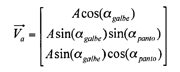

En faisant l'hypothèse que la face avant de la lentille ophtalmique 10 est circonscrite à une sphère de rayon R et que cette sphère passe par les deux points milieux P20, P21 des deux petits côtés du cadre boxing 33, on en déduit que le centre C de cette sphère présente, dans le premier repère, les coordonnées suivantes : 
Ces coordonnées, exprimées dans le second repère, s'expriment alors ainsi : 
Connaissant les coordonnées de cette sphère, il est alors possible de déterminer la position du point pupillaire Pc dans le premier repère. Ses coordonnées sont les suivantes : 
Le point de projection du point pupillaire Pc dans le second repère est appelé point pupillaire projeté Pcp. Ses coordonnées s'expriment ainsi : 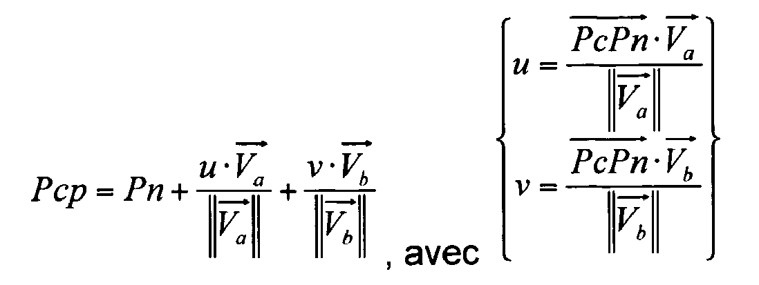
Le demi-écart pupillaire dPDc et la hauteur pupillaire Hc corrigés en tenant compte des angles de galbe et pantoscopique peuvent donc être calculés ainsi : ![]()
![]()
![]()
![]()
Par conséquent, les composantes dx et dy du vecteur de décalage s'expriment ainsi : ![]()
![]()
![]()
![]()
A titre illustratif, la composante dx du vecteur de décalage atteint une valeur de 0,7 millimètre pour une monture de lunettes fortement galbée, présentant les caractéristiques suivantes : A = 60mm ; B = 26mm ; dPD = 33 mm ; H = 13mm ; D = 18mm ; αpanto = 10° ; αgalbe = 25°.As an illustration, the dx component of the offset vector reaches a value of 0.7 millimeters for a highly curved spectacle frame, having the following characteristics: A = 60 mm; B = 26mm; dPD = 33 mm; H = 13mm; D = 18mm; α panto = 10 °; α curve = 25 °.
Le calcul de l'angle de décalage dθ est réalisé de manière homologue. On considère pour ce calcul le vecteur Vaxe comme le vecteur qui définit la direction de l'axe de la lentille dans le premier repère. Ce vecteur s'exprime ainsi : 
On définit le vecteur Vaxe2 comme le projeté du vecteur Vaxe dans le second repère. Ce vecteur Vaxe2 s'exprime ainsi : 
La coordonnée t peut être calculée en considérant le vecteur directeur Vc, qui égal au produit vectoriel des vecteurs Va et Vb. En effet, le produit vectoriel de ce vecteur directeur Vc par le vecteur Vaxe2 est nul. La coordonnée t du vecteur Vaxe2 peut donc être calculée au moyen de la formule suivante : 
Grâce à ce vecteur Vaxe2, on peut alors déduire l'angle de décalage dθ en considérant deux cas.With this vector Vaxe2, we can then deduce the offset angle dθ by considering two cases.
Si l'angle pantoscopique αpanto est non nul, ![]()

![]()
Si l'angle pantoscopique αpanto est nul, ![]()
![]()
![]()
![]()
A titre illustratif, l'angle de décalage dθ pour la monture de lunettes précitée est égal 4,26 degrés.As an illustration, the offset angle dθ for the above-mentioned spectacle frame is equal to 4.26 degrees.
A ce stade, grâce aux valeurs des composantes horizontale dx et verticale dy du vecteur de décalage et grâce à l'angle de décalage dθ, l'unité de traitement peut précisément déterminer, comme cela apparaît sur la
Une fois les deux référentiels mis en coïncidence, le logiciel commande l'affichage sur l'écran de visualisation 105 du profil longitudinal 30', qui est alors décalé par rapport au profil longitudinal 30 déjà affiché (
Préférentiellement, le logiciel commande également l'affichage sur l'écran de visualisation 105 du contour initial (circulaire) de la lentille ophtalmique 10. De cette manière, l'opticien peut vérifier que le profil longitudinal 30' ne sort pas du contour de la lentille ophtalmique 10. Cette vérification peut bien sur également être réalisée automatiquement par le logiciel.Preferably, the software also controls the display on the
Si le profil longitudinal 30' sort du contour circulaire de la lentille ophtalmique 10, alors l'opticien ou le logiciel peut mettre en oeuvre un procédé de correction de la position et/ou de l'orientation du profil longitudinal 30', du type de celui décrit dans le document
Le procédé de centrage est quoi qu'il en soit suivi, d'une étape de blocage et d'une étape de détourage de la lentille ophtalmique 10.The centering method is followed anyway, a blocking step and a step of trimming the
L'étape de blocage est réalisée par le dispositif centreur bloqueur 100 de la
Au cours de cette étape, le bras de positionnement 106 positionne l'organe de blocage sur la face avant de la lentille ophtalmique 10, en un point de blocage donné et avec une orientation de blocage donnée par rapport au référentiel de la lentille ophtalmique. Ainsi, lorsque la lentille munie de son organe de blocage est transférée sur l'appareil de détourage, ce dernier peut connaître la position et l'orientation du référentiel de la lentille et détourer la lentille dans ce référentiel.During this step, the
Le point de blocage est généralement choisi pour correspondre au centre du cadre boxing 33, c'est-à-dire au point d'intersection des diagonales de ce cadre. Cette position permet de s'assurer que lorsque la lentille est usinée, l'outil d'usinage reste à distance de l'organe de blocage et le contourne sans venir l'usiner.The locking point is generally chosen to correspond to the center of the
Dans ce mode de réalisation de l'invention, la lentille est centrée avant d'être bloquée. De cette manière, le choix du point de blocage et de l'orientation de blocage tient déjà compte du décalage du référentiel du cercle 21 par rapport au référentiel de la lentille 10. Par conséquent, ce décalage n'a plus à être pris en compte au stade du détourage de la lentille, puisque l'organe de blocage est déjà correctement centré par rapport au profil longitudinal 30'.In this embodiment of the invention, the lens is centered before being locked. In this way, the choice of the blocking point and the blocking orientation already takes into account the offset of the reference frame of the
En variante, selon un second mode de réalisation, on pourrait prévoir de bloquer la lentille avant même d'avoir mis le référentiel de la lentille 10 en coïncidence avec le référentiel du cercle 21 de la monture de lunettes 20. On comprend que dans ce cas, la position et l'orientation de l'organe de blocage sont déterminées en fonction de la position du profil longitudinal 30. Il convient alors, au stade du détourage, d'usiner la lentille en décalant la position et l'orientation du profil longitudinal 30' par rapport à l'organe de blocage.In a variant, according to a second embodiment, it would be possible to block the lens even before having set the reference frame of the
L'organe de blocage est ici réalisé en trois parties, dont un gland adapté à être bloqué sur l'appareil de détourage, un élément intermédiaire appelé « pad », et un autocollant « appelé sticker » à coller sur la face avant de la lentille. Ici, le « sticker » est collé sur la lentille en même temps que le « pad » et que le gland. En effet, s'il était collé sur la lentille avant le centrage de cette lentille, il risquerait de gêner les mesures optiques de centrage. Plus précisément, quand bien même il serait transparent, ce « sticker » risquerait de rendre plus difficile et moins précise l'acquisition de la position du point de centrage P1 et de l'orientation de sa ligne de repérage 11.The locking member is here made in three parts, including an acorn adapted to be blocked on the trimming apparatus, an intermediate element called "pad", and a sticker called "sticker" to be adhered to the front face of the lens . Here, the "sticker" is stuck on the lens at the same time as the "pad" and that the glans. Indeed, if it was stuck on the lens before the centering of this lens, it may interfere with the optical centering measures. More specifically, even though it would be transparent, this "sticker" could make it more difficult and less accurate to acquire the position of the centering point P1 and the orientation of its
Par conséquent, ici, le « pad » est tout d'abord collé sur le sticker, en le centrant et éventuellement en l'orientant convenable, puis le gland est collé sur le « pad », et enfin, l'ensemble est collé sur la lentille après l'opération de centrage.Therefore, here, the "pad" is first glued on the sticker, centering it and possibly orienting it properly, then the glans is stuck on the "pad", and finally, the whole is stuck on the lens after the centering operation.
L'étape de détourage de la lentille ophtalmique est quant à elle réalisée au moyen d'un appareil de détourage 130 du type de celui représenté schématiquement sur la
Cet appareil de détourage 130 comprend ici des moyens de support formés par des arbres 131 de maintien et d'entraînement en rotation de la lentille ophtalmique 10 autour d'un axe de blocage A4. Un tel appareil de détourage comprend en outre des moyens de détourage formés par un outil d'usinage 132 monté rotatif autour d'un axe d'usinage A5 qui est ici sensiblement parallèle à l'axe de blocage A4, mais qui pourrait également être incliné par rapport à cet axe.This
L'outil d'usinage 132 et/ou les arbres 131 sont pourvus de deux mobilités relatives, dont une mobilité radiale permettant de modifier l'écartement entre l'axe d'usinage A5 et l'axe de blocage A4, et une mobilité de translation axiale selon un axe parallèle à l'axe de blocage A4.The
L'appareil de détourage 130 comporte en outre un dispositif électronique et/ou informatique (non représenté) qui est pourvu, d'une part, de moyens de communication avec le dispositif centreur-bloqueur 100, et, d'autre part, de moyens de pilotage des mobilités des arbres 131 et de l'outil d'usinage 132. Ce dispositif électronique et/ou informatique permet en particulier de piloter, pour chaque position angulaire de la lentille 10 autour de l'axe de blocage A4, l'écartement radial entre l'outil d'usinage 132 et l'axe de blocage A4, ainsi que la position axiale de la tranche de la lentille par rapport à la surface de travail de l'outil d'usinage 132.The
Comme le montre plus particulièrement la
Dans le mode de réalisation exposé, le calcul du décalage entre les deux référentiels est réalisé par le dispositif centreur-bloqueur 100. Bien sûr, ce calcul pourrait également être réalisé par le dispositif électronique et/ou informatique de l'appareil de détourage 130.In the embodiment shown, the calculation of the offset between the two reference frames is carried out by the centering-blocking
La présente invention n'est nullement limitée aux modes de réalisation décrits et représentés, mais l'homme du métier saura y apporter toute variante conforme à son esprit.The present invention is not limited to the embodiments described and shown, but the skilled person will be able to make any variant within his mind.
En particulier, dans le cas où la monture de lunettes choisie par le porteur est du type percé (sans cercle), les positions des trous de perçage seront avantageusement déterminées dans le référentiel de la lentille ophtalmique 10, après sa mise en coïncidence avec le référentiel du cercle 21 de la monture de lunettes 20. On pourra également prévoir de calculer l'orientation de l'axe de perçage de chacun des trous de perçage dans ce même référentiel, afin de tenir compte de l'angle de galbe αgalbe et de l'angle pantoscopique αpanto de la monture de lunettes.In particular, in the case where the eyeglass frame chosen by the wearer is of the pierced type (without a circle), the positions of the piercing holes will advantageously be determined in the reference system of the
Dans un autre mode de réalisation de l'invention, on peut prévoir d'utiliser un registre de base de données pour déterminer les composantes dx, dy du vecteur de décalage et l'angle de décalage dθ.In another embodiment of the invention, provision may be made to use a database register to determine the components dx, dy of the offset vector and the offset angle dθ.
Ce registre de base de données comportera alors une pluralité d'enregistrements chacun associés à un type de montures de lunettes référencé. Chaque enregistrement comprendra un identifiant du type de montures de lunettes référencé, un paramètre de galbe ou de compensation de galbe propre à ce type de montures de lunettes référencé, et un paramètre pantoscopique ou de compensation pantoscopique propre à ce type de montures de lunettes référencé.This database register will then comprise a plurality of records each associated with a type of glasses frames referenced. Each record will include an identifier of the type of glasses frames referenced, a curvature parameter or curve compensation specific to this type of glasses frames referenced, and a pantoscopic parameter or pantoscopic compensation specific to this type of glasses frames referenced.
Ce paramètre de galbe sera préférentiellement formé par l'angle de galbe αgalbe de la monture. Le paramètre pantoscopique sera quant à lui préférentiellement formé par l'angle pantoscopique αpanto de la monture.This curve parameter will preferably be formed by the curve angle α curve of the frame. The pantoscopic parameter will be preferentially formed by the pantoscopic angle α panto of the frame.
De cette manière, pour acquérir le paramètre de galbe de la monture 20 choisie par le porteur, il faudra chercher dans le registre un enregistrement correspondant à cette monture de lunettes 20, puis lire dans cet enregistrement le paramètre de galbe associé.In this way, in order to acquire the curvature parameter of the frame chosen by the wearer, it will be necessary to look in the register for a record corresponding to this
On pourra éventuellement prévoir, si aucun enregistrement n'est trouvé, d'acquérir les angles de galbe αgalbe et/ou pantoscopique αpanto de la monture de lunettes 20 par l'une des méthodes décrites précédemment, puis de créer dans le registre un nouvel enregistrement correspondant à la monture de lunettes 20 choisie, afin d'y mémoriser le paramètre de galbe acquis.If no record is found, it may be possible to predict the α- curve and / or pantoscopic α- panto curve angles of the
Par la suite, les calculs des composantes dx, dy du vecteur de décalage et de l'angle de décalage dθ pourront être effectués selon la même méthode que celle décrite supra.Subsequently, the computations of the components dx, dy of the offset vector and the offset angle dθ can be performed according to the same method as that described above.
En variante, le registre de base de données pourra comporter un identifiant du type de montures de lunettes référencé, un paramètre de compensation de galbe propre à ce type de montures de lunettes référencé, et un paramètre de compensation pantoscopique propre à ce type de montures de lunettes référencé.As a variant, the database register may include an identifier of the type of glasses frames referenced, a curve compensation parameter specific to this type of glasses frames referenced, and a pantoscopic compensation parameter specific to this type of frames of glasses. glasses referenced.
Dans cette variante, les paramètres mémorisés ne sont donc plus les angles de galbe αgalbe et/ou pantoscopique αpanto de la monture de lunettes 20, mais directement les composantes dx, dy du vecteur de décalage et l'angle de décalage dθ. Ce registre permet ainsi de se passer de l'étape de calcul de ces composantes dx, dy et de l'angle de décalage dθ.In this variant, the stored parameters are no longer angles α contour curve and / or α pantoscopic panto of the
Dans cette variante, chaque enregistrement du registre de base de données est associé à une monture de lunettes et comporte une pluralité de champs chacun associés à une prescription du porteur. Plus précisément, chaque champ est associé à un angle θAxeVerre donné, à un demi-écart pupillaire dPD donné et à une hauteur pupillaire H donnée.In this variant, each record of the database register is associated with a spectacle frame and has a plurality of fields each associated with a prescription of the wearer. More precisely, each field is associated with a given angle θ givenGlass , with a given pupil half-distance dPD and with a given pupil height H.
L'opticien pourra ainsi, à partir de l'identifiant de la monture, rechercher dans le registre un enregistrement correspondant à la monture choisie par le porteur, puis, à partir des prescriptions θAxeVerre, dPD et H du porteur, déterminer le champ correspondant à ces prescriptions, afin d'acquérir les composantes dx, dy du vecteur de décalage et l'angle de décalage dθ correspondant.The optician can thus, from the identifier of the mount, search the register for a record corresponding to the mount chosen by the wearer, then, from the prescriptions θ AxEdge , dPD and H of the wearer, determine the field corresponding to these requirements, in order to acquire the components dx, dy of the offset vector and the corresponding offset angle dθ.
Bien sûr, ici également, si ces données ne sont pas déjà mémorisées dans le registre de base de données, on pourra prévoir de les acquérir suivant l'une des méthodes décrites précédemment, afin de les mémoriser dans un nouveau champ d'un enregistrement du registre de base de données.Of course, here too, if these data are not already stored in the database register, provision can be made to acquire them according to one of the methods described above, in order to store them in a new field of a record of database register.
Claims (15)
Applications Claiming Priority (1)
| Application Number | Priority Date | Filing Date | Title |
|---|---|---|---|
| FR0806986A FR2939915B1 (en) | 2008-12-12 | 2008-12-12 | PROCESS FOR PREPARING AN OPHTHALMIC LENS FOR MOUNTING ON A CAMBREE GOGGLE FRAME |
Publications (2)
| Publication Number | Publication Date |
|---|---|
| EP2196845A1 true EP2196845A1 (en) | 2010-06-16 |
| EP2196845B1 EP2196845B1 (en) | 2015-06-03 |
Family
ID=40473366
Family Applications (1)
| Application Number | Title | Priority Date | Filing Date |
|---|---|---|---|
| EP09290889.6A Active EP2196845B1 (en) | 2008-12-12 | 2009-11-30 | Method for preparing an ophthalmic lens in order to mount it on a curved spectacle frame |
Country Status (3)
| Country | Link |
|---|---|
| US (1) | US8419183B2 (en) |
| EP (1) | EP2196845B1 (en) |
| FR (1) | FR2939915B1 (en) |
Families Citing this family (5)
| Publication number | Priority date | Publication date | Assignee | Title |
|---|---|---|---|---|
| FR2959831B1 (en) * | 2010-05-10 | 2013-02-15 | Essilor Int | PROCESS FOR PREPARING AN OPHTHALMIC LENS EQUIPPED WITH A MEMORY MARK |
| FR3013620B1 (en) * | 2013-11-26 | 2015-12-25 | Essilor Int | METHOD FOR BEVELING AN OPHTHALMIC LENS |
| TWI756600B (en) * | 2019-12-12 | 2022-03-01 | 華碩電腦股份有限公司 | Measuring method of lens frame wearing parameters and measuring equipment thereof |
| EP3876026A1 (en) | 2020-03-06 | 2021-09-08 | Carl Zeiss Vision International GmbH | Method and devices for determining inclination angle |
| CN113608363B (en) * | 2021-08-24 | 2023-04-14 | 江苏康耐特光学有限公司 | Front bending degree design method for preparing high-refractive-index resin lens |
Citations (9)
| Publication number | Priority date | Publication date | Assignee | Title |
|---|---|---|---|---|
| ES2043546A2 (en) | 1992-04-24 | 1993-12-16 | Indo Int Sa | Apparatus for measuring optical parameters for ophthalmic lenses |
| US5617155A (en) | 1994-05-03 | 1997-04-01 | Essilor International | Method for determining measurement parameters for a spectacle wearer |
| US5802731A (en) | 1995-06-23 | 1998-09-08 | Essilor International Compagnie Generale D'optique | Calibration gage for calibrating a device for reading off eyeglass frame contours, and corresponding calibration method |
| WO2007012713A1 (en) * | 2005-07-26 | 2007-02-01 | Essilor International (Compagnie Generale D'optique) | Method for trimming an ophthalmologic lens with reacquisition of an initial centering reference frame |
| WO2007026058A1 (en) | 2005-08-31 | 2007-03-08 | Essilor International (Compagnie Generale D'optique) | Method for centering an uncut ophthalmic lens whose center point is offset with regard to the geometric center |
| WO2007128925A1 (en) | 2006-05-10 | 2007-11-15 | Essilor International (Compagnie Générale d'Optique) | Method for centering an ophthalmic lens on a curved spectacle frame |
| FR2906047A1 (en) * | 2006-09-14 | 2008-03-21 | Essilor Int | METHOD AND DEVICE FOR DETERMINING THE ORIENTATION OF A PERFECT OPHTHALMIC LENS AND METHOD FOR OPTICALLY DESIGNING THE CORRECTING LENS |
| FR2910647A1 (en) * | 2007-05-29 | 2008-06-27 | Essilor Int | Ophthalmic lens trimming method for use in spectacles, involves storing focusing and trimming characteristics of frame in new recordings of central register associated to type of frame, and acquiring characteristics of another frame |
| FR2915290A1 (en) * | 2007-04-18 | 2008-10-24 | Essilor Int | METHOD FOR MEASURING AT LEAST ONE GEOMETRICAL-PHYSIOMICAL PARAMETER FOR IMPLANTATION OF A FRAME OF VISUAL CORRECTION GLASSES ON THE FACE OF A BEARER |
Family Cites Families (1)
| Publication number | Priority date | Publication date | Assignee | Title |
|---|---|---|---|---|
| FR2910674A1 (en) | 2006-12-21 | 2008-06-27 | France Telecom | Building's frontage structured image analyzing method, involves merging vertical or horizontal basic histogram with vertical or horizontal contour histogram, in vertical window histogram or horizontal window histogram |
-
2008
- 2008-12-12 FR FR0806986A patent/FR2939915B1/en active Active
-
2009
- 2009-11-30 EP EP09290889.6A patent/EP2196845B1/en active Active
- 2009-12-10 US US12/634,774 patent/US8419183B2/en active Active
Patent Citations (9)
| Publication number | Priority date | Publication date | Assignee | Title |
|---|---|---|---|---|
| ES2043546A2 (en) | 1992-04-24 | 1993-12-16 | Indo Int Sa | Apparatus for measuring optical parameters for ophthalmic lenses |
| US5617155A (en) | 1994-05-03 | 1997-04-01 | Essilor International | Method for determining measurement parameters for a spectacle wearer |
| US5802731A (en) | 1995-06-23 | 1998-09-08 | Essilor International Compagnie Generale D'optique | Calibration gage for calibrating a device for reading off eyeglass frame contours, and corresponding calibration method |
| WO2007012713A1 (en) * | 2005-07-26 | 2007-02-01 | Essilor International (Compagnie Generale D'optique) | Method for trimming an ophthalmologic lens with reacquisition of an initial centering reference frame |
| WO2007026058A1 (en) | 2005-08-31 | 2007-03-08 | Essilor International (Compagnie Generale D'optique) | Method for centering an uncut ophthalmic lens whose center point is offset with regard to the geometric center |
| WO2007128925A1 (en) | 2006-05-10 | 2007-11-15 | Essilor International (Compagnie Générale d'Optique) | Method for centering an ophthalmic lens on a curved spectacle frame |
| FR2906047A1 (en) * | 2006-09-14 | 2008-03-21 | Essilor Int | METHOD AND DEVICE FOR DETERMINING THE ORIENTATION OF A PERFECT OPHTHALMIC LENS AND METHOD FOR OPTICALLY DESIGNING THE CORRECTING LENS |
| FR2915290A1 (en) * | 2007-04-18 | 2008-10-24 | Essilor Int | METHOD FOR MEASURING AT LEAST ONE GEOMETRICAL-PHYSIOMICAL PARAMETER FOR IMPLANTATION OF A FRAME OF VISUAL CORRECTION GLASSES ON THE FACE OF A BEARER |
| FR2910647A1 (en) * | 2007-05-29 | 2008-06-27 | Essilor Int | Ophthalmic lens trimming method for use in spectacles, involves storing focusing and trimming characteristics of frame in new recordings of central register associated to type of frame, and acquiring characteristics of another frame |
Also Published As
| Publication number | Publication date |
|---|---|
| US20100157243A1 (en) | 2010-06-24 |
| FR2939915B1 (en) | 2011-01-14 |
| US8419183B2 (en) | 2013-04-16 |
| FR2939915A1 (en) | 2010-06-18 |
| EP2196845B1 (en) | 2015-06-03 |
Similar Documents
| Publication | Publication Date | Title |
|---|---|---|
| EP1817562B9 (en) | Device for automatically measuring characteristics of an ophthalmic lens | |
| EP1825243B1 (en) | Method and device for measuring the power of an ophthalmic lens by global contact-free optical measuring and tracing | |
| EP1827756B1 (en) | Device for automatic mounting preparation of ophthalmic lenses enabling several lenses to be processed at the same time | |
| EP2139642B1 (en) | Device and method for preparing an ophthalmic lens for machining | |
| EP1836025B1 (en) | Method and device for automatically preparing an ophthalmic lens to be mounted | |
| EP1827757B1 (en) | Method and device for mounting preparation for a job of two ophthalmic lenses for the same pair of glasses | |
| EP1833639B1 (en) | Method and device for automatic mounting preparation an ophthalmic lens | |
| EP2196845B1 (en) | Method for preparing an ophthalmic lens in order to mount it on a curved spectacle frame | |
| EP2091689B1 (en) | Device for determining the position and/or transverse dimension of a drill hole in a lens for the presentation of spectacles with a rimless frame | |
| EP2210703B1 (en) | Eyeglass lens processing apparatus | |
| EP1722923B1 (en) | Method for manually centering an ophthalmic lens in a centering/locking device and associated centering/locking device | |
| EP2091690B9 (en) | Method for determining the position of a drill hole to be formed in an ophthalmic lens | |
| WO2007128925A1 (en) | Method for centering an ophthalmic lens on a curved spectacle frame | |
| WO2006061477A1 (en) | Method and device for automatic mounting preparation for an ophthalmic lens with the aid of a pair of gripping, transferring and locking noses | |
| WO2006061475A1 (en) | Method for locking an ophthalmic lens for the trimming thereof and device for automatic mounting preparation of an ophthalmic lens | |
| EP1882207B1 (en) | Method for recording geometrical characteristics of a second lens by means of scanning a first lens both lenses being from the same batch | |
| FR2878969A1 (en) | DEVICE FOR AUTOMATICALLY PREPARING THE MOUNTING OF OPHTHALMIC LENSES COMPRISING IMMOBILIZATION AND TRANSFER MEANS | |
| FR2878976A1 (en) | Ophthalmic lens locking method for spectacles, involves fixing reference mallet on lens by adhesive application surface and cooperating non adhesive application surface of locking nose by friction with lens for immobilizing lens | |
| FR2878974A1 (en) | ORGAN FOR HANDLING AND PALPING AN OPHTHALMIC LENS OF GOGGLES AND DEVICE FOR AUTOMATICALLY PREPARING THE MOUNTING OF OPHTHALMIC LENSES COMPRISING SUCH A BODY |
Legal Events
| Date | Code | Title | Description |
|---|---|---|---|
| PUAI | Public reference made under article 153(3) epc to a published international application that has entered the european phase |
Free format text: ORIGINAL CODE: 0009012 |
|
| AK | Designated contracting states |
Kind code of ref document: A1 Designated state(s): AT BE BG CH CY CZ DE DK EE ES FI FR GB GR HR HU IE IS IT LI LT LU LV MC MK MT NL NO PL PT RO SE SI SK SM TR |
|
| AX | Request for extension of the european patent |
Extension state: AL BA RS |
|
| 17P | Request for examination filed |
Effective date: 20100706 |
|
| GRAP | Despatch of communication of intention to grant a patent |
Free format text: ORIGINAL CODE: EPIDOSNIGR1 |
|
| RIC1 | Information provided on ipc code assigned before grant |
Ipc: G02C 13/00 20060101AFI20150113BHEP |
|
| INTG | Intention to grant announced |
Effective date: 20150213 |
|
| RIN1 | Information on inventor provided before grant (corrected) |
Inventor name: BOUTINON, STEPHANE |
|
| GRAS | Grant fee paid |
Free format text: ORIGINAL CODE: EPIDOSNIGR3 |
|
| GRAA | (expected) grant |
Free format text: ORIGINAL CODE: 0009210 |
|
| AK | Designated contracting states |
Kind code of ref document: B1 Designated state(s): AT BE BG CH CY CZ DE DK EE ES FI FR GB GR HR HU IE IS IT LI LT LU LV MC MK MT NL NO PL PT RO SE SI SK SM TR |
|
| REG | Reference to a national code |
Ref country code: GB Ref legal event code: FG4D Free format text: NOT ENGLISH |
|
| REG | Reference to a national code |
Ref country code: CH Ref legal event code: EP |
|
| REG | Reference to a national code |
Ref country code: AT Ref legal event code: REF Ref document number: 730204 Country of ref document: AT Kind code of ref document: T Effective date: 20150715 Ref country code: IE Ref legal event code: FG4D Free format text: LANGUAGE OF EP DOCUMENT: FRENCH |
|
| REG | Reference to a national code |
Ref country code: DE Ref legal event code: R096 Ref document number: 602009031528 Country of ref document: DE |
|
| REG | Reference to a national code |
Ref country code: AT Ref legal event code: MK05 Ref document number: 730204 Country of ref document: AT Kind code of ref document: T Effective date: 20150603 |
|
| PG25 | Lapsed in a contracting state [announced via postgrant information from national office to epo] |
Ref country code: HR Free format text: LAPSE BECAUSE OF FAILURE TO SUBMIT A TRANSLATION OF THE DESCRIPTION OR TO PAY THE FEE WITHIN THE PRESCRIBED TIME-LIMIT Effective date: 20150603 Ref country code: FI Free format text: LAPSE BECAUSE OF FAILURE TO SUBMIT A TRANSLATION OF THE DESCRIPTION OR TO PAY THE FEE WITHIN THE PRESCRIBED TIME-LIMIT Effective date: 20150603 Ref country code: NO Free format text: LAPSE BECAUSE OF FAILURE TO SUBMIT A TRANSLATION OF THE DESCRIPTION OR TO PAY THE FEE WITHIN THE PRESCRIBED TIME-LIMIT Effective date: 20150903 Ref country code: ES Free format text: LAPSE BECAUSE OF FAILURE TO SUBMIT A TRANSLATION OF THE DESCRIPTION OR TO PAY THE FEE WITHIN THE PRESCRIBED TIME-LIMIT Effective date: 20150603 Ref country code: LT Free format text: LAPSE BECAUSE OF FAILURE TO SUBMIT A TRANSLATION OF THE DESCRIPTION OR TO PAY THE FEE WITHIN THE PRESCRIBED TIME-LIMIT Effective date: 20150603 |
|
| REG | Reference to a national code |
Ref country code: NL Ref legal event code: MP Effective date: 20150603 |
|
| REG | Reference to a national code |
Ref country code: FR Ref legal event code: PLFP Year of fee payment: 7 |
|
| REG | Reference to a national code |
Ref country code: LT Ref legal event code: MG4D |
|
| PG25 | Lapsed in a contracting state [announced via postgrant information from national office to epo] |
Ref country code: AT Free format text: LAPSE BECAUSE OF FAILURE TO SUBMIT A TRANSLATION OF THE DESCRIPTION OR TO PAY THE FEE WITHIN THE PRESCRIBED TIME-LIMIT Effective date: 20150603 Ref country code: GR Free format text: LAPSE BECAUSE OF FAILURE TO SUBMIT A TRANSLATION OF THE DESCRIPTION OR TO PAY THE FEE WITHIN THE PRESCRIBED TIME-LIMIT Effective date: 20150904 Ref country code: BG Free format text: LAPSE BECAUSE OF FAILURE TO SUBMIT A TRANSLATION OF THE DESCRIPTION OR TO PAY THE FEE WITHIN THE PRESCRIBED TIME-LIMIT Effective date: 20150903 Ref country code: LV Free format text: LAPSE BECAUSE OF FAILURE TO SUBMIT A TRANSLATION OF THE DESCRIPTION OR TO PAY THE FEE WITHIN THE PRESCRIBED TIME-LIMIT Effective date: 20150603 |
|
| PG25 | Lapsed in a contracting state [announced via postgrant information from national office to epo] |
Ref country code: EE Free format text: LAPSE BECAUSE OF FAILURE TO SUBMIT A TRANSLATION OF THE DESCRIPTION OR TO PAY THE FEE WITHIN THE PRESCRIBED TIME-LIMIT Effective date: 20150603 |
|
| PG25 | Lapsed in a contracting state [announced via postgrant information from national office to epo] |
Ref country code: PT Free format text: LAPSE BECAUSE OF FAILURE TO SUBMIT A TRANSLATION OF THE DESCRIPTION OR TO PAY THE FEE WITHIN THE PRESCRIBED TIME-LIMIT Effective date: 20151006 Ref country code: CZ Free format text: LAPSE BECAUSE OF FAILURE TO SUBMIT A TRANSLATION OF THE DESCRIPTION OR TO PAY THE FEE WITHIN THE PRESCRIBED TIME-LIMIT Effective date: 20150603 Ref country code: PL Free format text: LAPSE BECAUSE OF FAILURE TO SUBMIT A TRANSLATION OF THE DESCRIPTION OR TO PAY THE FEE WITHIN THE PRESCRIBED TIME-LIMIT Effective date: 20150603 Ref country code: IS Free format text: LAPSE BECAUSE OF FAILURE TO SUBMIT A TRANSLATION OF THE DESCRIPTION OR TO PAY THE FEE WITHIN THE PRESCRIBED TIME-LIMIT Effective date: 20151003 Ref country code: SK Free format text: LAPSE BECAUSE OF FAILURE TO SUBMIT A TRANSLATION OF THE DESCRIPTION OR TO PAY THE FEE WITHIN THE PRESCRIBED TIME-LIMIT Effective date: 20150603 Ref country code: RO Free format text: LAPSE BECAUSE OF NON-PAYMENT OF DUE FEES Effective date: 20150603 |
|
| REG | Reference to a national code |
Ref country code: DE Ref legal event code: R097 Ref document number: 602009031528 Country of ref document: DE |
|
| PLBE | No opposition filed within time limit |
Free format text: ORIGINAL CODE: 0009261 |
|
| STAA | Information on the status of an ep patent application or granted ep patent |
Free format text: STATUS: NO OPPOSITION FILED WITHIN TIME LIMIT |
|
| PG25 | Lapsed in a contracting state [announced via postgrant information from national office to epo] |
Ref country code: IT Free format text: LAPSE BECAUSE OF FAILURE TO SUBMIT A TRANSLATION OF THE DESCRIPTION OR TO PAY THE FEE WITHIN THE PRESCRIBED TIME-LIMIT Effective date: 20150603 Ref country code: DK Free format text: LAPSE BECAUSE OF FAILURE TO SUBMIT A TRANSLATION OF THE DESCRIPTION OR TO PAY THE FEE WITHIN THE PRESCRIBED TIME-LIMIT Effective date: 20150603 |
|
| 26N | No opposition filed |
Effective date: 20160304 |
|
| PG25 | Lapsed in a contracting state [announced via postgrant information from national office to epo] |
Ref country code: SI Free format text: LAPSE BECAUSE OF FAILURE TO SUBMIT A TRANSLATION OF THE DESCRIPTION OR TO PAY THE FEE WITHIN THE PRESCRIBED TIME-LIMIT Effective date: 20150603 |
|
| PG25 | Lapsed in a contracting state [announced via postgrant information from national office to epo] |
Ref country code: LU Free format text: LAPSE BECAUSE OF FAILURE TO SUBMIT A TRANSLATION OF THE DESCRIPTION OR TO PAY THE FEE WITHIN THE PRESCRIBED TIME-LIMIT Effective date: 20151130 Ref country code: MC Free format text: LAPSE BECAUSE OF FAILURE TO SUBMIT A TRANSLATION OF THE DESCRIPTION OR TO PAY THE FEE WITHIN THE PRESCRIBED TIME-LIMIT Effective date: 20150603 |
|
| REG | Reference to a national code |
Ref country code: CH Ref legal event code: PL |
|
| PG25 | Lapsed in a contracting state [announced via postgrant information from national office to epo] |
Ref country code: CH Free format text: LAPSE BECAUSE OF NON-PAYMENT OF DUE FEES Effective date: 20151130 Ref country code: LI Free format text: LAPSE BECAUSE OF NON-PAYMENT OF DUE FEES Effective date: 20151130 |
|
| REG | Reference to a national code |
Ref country code: IE Ref legal event code: MM4A |
|
| PG25 | Lapsed in a contracting state [announced via postgrant information from national office to epo] |
Ref country code: IE Free format text: LAPSE BECAUSE OF NON-PAYMENT OF DUE FEES Effective date: 20151130 |
|
| REG | Reference to a national code |
Ref country code: FR Ref legal event code: PLFP Year of fee payment: 8 |
|
| PG25 | Lapsed in a contracting state [announced via postgrant information from national office to epo] |
Ref country code: SM Free format text: LAPSE BECAUSE OF FAILURE TO SUBMIT A TRANSLATION OF THE DESCRIPTION OR TO PAY THE FEE WITHIN THE PRESCRIBED TIME-LIMIT Effective date: 20150603 Ref country code: HU Free format text: LAPSE BECAUSE OF FAILURE TO SUBMIT A TRANSLATION OF THE DESCRIPTION OR TO PAY THE FEE WITHIN THE PRESCRIBED TIME-LIMIT; INVALID AB INITIO Effective date: 20091130 |
|
| PG25 | Lapsed in a contracting state [announced via postgrant information from national office to epo] |
Ref country code: CY Free format text: LAPSE BECAUSE OF FAILURE TO SUBMIT A TRANSLATION OF THE DESCRIPTION OR TO PAY THE FEE WITHIN THE PRESCRIBED TIME-LIMIT Effective date: 20150603 Ref country code: SE Free format text: LAPSE BECAUSE OF FAILURE TO SUBMIT A TRANSLATION OF THE DESCRIPTION OR TO PAY THE FEE WITHIN THE PRESCRIBED TIME-LIMIT Effective date: 20150603 Ref country code: NL Free format text: LAPSE BECAUSE OF FAILURE TO SUBMIT A TRANSLATION OF THE DESCRIPTION OR TO PAY THE FEE WITHIN THE PRESCRIBED TIME-LIMIT Effective date: 20150603 |
|
| PG25 | Lapsed in a contracting state [announced via postgrant information from national office to epo] |
Ref country code: BE Free format text: LAPSE BECAUSE OF NON-PAYMENT OF DUE FEES Effective date: 20151130 |
|
| PG25 | Lapsed in a contracting state [announced via postgrant information from national office to epo] |
Ref country code: MT Free format text: LAPSE BECAUSE OF FAILURE TO SUBMIT A TRANSLATION OF THE DESCRIPTION OR TO PAY THE FEE WITHIN THE PRESCRIBED TIME-LIMIT Effective date: 20150603 Ref country code: TR Free format text: LAPSE BECAUSE OF FAILURE TO SUBMIT A TRANSLATION OF THE DESCRIPTION OR TO PAY THE FEE WITHIN THE PRESCRIBED TIME-LIMIT Effective date: 20150603 |
|
| REG | Reference to a national code |
Ref country code: FR Ref legal event code: PLFP Year of fee payment: 9 |
|
| REG | Reference to a national code |
Ref country code: DE Ref legal event code: R081 Ref document number: 602009031528 Country of ref document: DE Owner name: ESSILOR INTERNATIONAL, FR Free format text: FORMER OWNER: ESSILOR INTERNATIONAL (COMPAGNIE GENERALE D'OPTIQUE), CHARENTON-LE-PONT, FR |
|
| PG25 | Lapsed in a contracting state [announced via postgrant information from national office to epo] |
Ref country code: MK Free format text: LAPSE BECAUSE OF FAILURE TO SUBMIT A TRANSLATION OF THE DESCRIPTION OR TO PAY THE FEE WITHIN THE PRESCRIBED TIME-LIMIT Effective date: 20150603 |
|
| REG | Reference to a national code |
Ref country code: FR Ref legal event code: TP Owner name: ESSILOR INTERNATIONAL, FR Effective date: 20180601 |
|
| P01 | Opt-out of the competence of the unified patent court (upc) registered |
Effective date: 20230525 |
|
| PGFP | Annual fee paid to national office [announced via postgrant information from national office to epo] |
Ref country code: GB Payment date: 20231127 Year of fee payment: 15 |
|
| PGFP | Annual fee paid to national office [announced via postgrant information from national office to epo] |
Ref country code: FR Payment date: 20231127 Year of fee payment: 15 Ref country code: DE Payment date: 20231129 Year of fee payment: 15 |