EP2196880B1 - Plant control system and method - Google Patents
Plant control system and method Download PDFInfo
- Publication number
- EP2196880B1 EP2196880B1 EP08835525.0A EP08835525A EP2196880B1 EP 2196880 B1 EP2196880 B1 EP 2196880B1 EP 08835525 A EP08835525 A EP 08835525A EP 2196880 B1 EP2196880 B1 EP 2196880B1
- Authority
- EP
- European Patent Office
- Prior art keywords
- arithmetic
- data
- programmable logic
- logic controller
- result data
- Prior art date
- Legal status (The legal status is an assumption and is not a legal conclusion. Google has not performed a legal analysis and makes no representation as to the accuracy of the status listed.)
- Active
Links
- 238000000034 method Methods 0.000 title claims description 37
- 238000012545 processing Methods 0.000 claims description 65
- 230000005540 biological transmission Effects 0.000 claims description 18
- 238000009628 steelmaking Methods 0.000 description 22
- 238000011161 development Methods 0.000 description 11
- 238000012795 verification Methods 0.000 description 10
- 238000004458 analytical method Methods 0.000 description 9
- 238000004519 manufacturing process Methods 0.000 description 9
- 238000004088 simulation Methods 0.000 description 7
- 230000006870 function Effects 0.000 description 5
- XEEYBQQBJWHFJM-UHFFFAOYSA-N Iron Chemical compound [Fe] XEEYBQQBJWHFJM-UHFFFAOYSA-N 0.000 description 4
- 229910000831 Steel Inorganic materials 0.000 description 3
- 238000004590 computer program Methods 0.000 description 3
- 230000010365 information processing Effects 0.000 description 3
- 238000005096 rolling process Methods 0.000 description 3
- 239000010959 steel Substances 0.000 description 3
- 238000010586 diagram Methods 0.000 description 2
- 238000005516 engineering process Methods 0.000 description 2
- 238000011156 evaluation Methods 0.000 description 2
- 239000000284 extract Substances 0.000 description 2
- 229910052742 iron Inorganic materials 0.000 description 2
- 230000000737 periodic effect Effects 0.000 description 2
- 230000002093 peripheral effect Effects 0.000 description 2
- 238000004886 process control Methods 0.000 description 2
- 230000002159 abnormal effect Effects 0.000 description 1
- 238000006243 chemical reaction Methods 0.000 description 1
- 238000004891 communication Methods 0.000 description 1
- 238000007405 data analysis Methods 0.000 description 1
- 239000003814 drug Substances 0.000 description 1
- 230000010354 integration Effects 0.000 description 1
- 238000005259 measurement Methods 0.000 description 1
- 238000012544 monitoring process Methods 0.000 description 1
- 239000004065 semiconductor Substances 0.000 description 1
- 238000003860 storage Methods 0.000 description 1
- 239000000126 substance Substances 0.000 description 1
- 238000012360 testing method Methods 0.000 description 1
Images


Classifications
-
- G—PHYSICS
- G05—CONTROLLING; REGULATING
- G05B—CONTROL OR REGULATING SYSTEMS IN GENERAL; FUNCTIONAL ELEMENTS OF SUCH SYSTEMS; MONITORING OR TESTING ARRANGEMENTS FOR SUCH SYSTEMS OR ELEMENTS
- G05B19/00—Programme-control systems
- G05B19/02—Programme-control systems electric
- G05B19/418—Total factory control, i.e. centrally controlling a plurality of machines, e.g. direct or distributed numerical control [DNC], flexible manufacturing systems [FMS], integrated manufacturing systems [IMS], computer integrated manufacturing [CIM]
- G05B19/41835—Total factory control, i.e. centrally controlling a plurality of machines, e.g. direct or distributed numerical control [DNC], flexible manufacturing systems [FMS], integrated manufacturing systems [IMS], computer integrated manufacturing [CIM] characterised by programme execution
-
- G—PHYSICS
- G05—CONTROLLING; REGULATING
- G05B—CONTROL OR REGULATING SYSTEMS IN GENERAL; FUNCTIONAL ELEMENTS OF SUCH SYSTEMS; MONITORING OR TESTING ARRANGEMENTS FOR SUCH SYSTEMS OR ELEMENTS
- G05B2219/00—Program-control systems
- G05B2219/10—Plc systems
- G05B2219/13—Plc programming
- G05B2219/13167—Personal computer pc
-
- G—PHYSICS
- G05—CONTROLLING; REGULATING
- G05B—CONTROL OR REGULATING SYSTEMS IN GENERAL; FUNCTIONAL ELEMENTS OF SUCH SYSTEMS; MONITORING OR TESTING ARRANGEMENTS FOR SUCH SYSTEMS OR ELEMENTS
- G05B2219/00—Program-control systems
- G05B2219/10—Plc systems
- G05B2219/15—Plc structure of the system
- G05B2219/15101—Personal computer pc and plc, slot plc, same kernel
-
- G—PHYSICS
- G05—CONTROLLING; REGULATING
- G05B—CONTROL OR REGULATING SYSTEMS IN GENERAL; FUNCTIONAL ELEMENTS OF SUCH SYSTEMS; MONITORING OR TESTING ARRANGEMENTS FOR SUCH SYSTEMS OR ELEMENTS
- G05B2219/00—Program-control systems
- G05B2219/30—Nc systems
- G05B2219/31—From computer integrated manufacturing till monitoring
- G05B2219/31225—System structure, plc's and pc's communicate over lan
-
- G—PHYSICS
- G05—CONTROLLING; REGULATING
- G05B—CONTROL OR REGULATING SYSTEMS IN GENERAL; FUNCTIONAL ELEMENTS OF SUCH SYSTEMS; MONITORING OR TESTING ARRANGEMENTS FOR SUCH SYSTEMS OR ELEMENTS
- G05B2219/00—Program-control systems
- G05B2219/30—Nc systems
- G05B2219/32—Operator till task planning
- G05B2219/32413—Pc generates control strategy, download in plc to monitor and react to events
-
- Y—GENERAL TAGGING OF NEW TECHNOLOGICAL DEVELOPMENTS; GENERAL TAGGING OF CROSS-SECTIONAL TECHNOLOGIES SPANNING OVER SEVERAL SECTIONS OF THE IPC; TECHNICAL SUBJECTS COVERED BY FORMER USPC CROSS-REFERENCE ART COLLECTIONS [XRACs] AND DIGESTS
- Y02—TECHNOLOGIES OR APPLICATIONS FOR MITIGATION OR ADAPTATION AGAINST CLIMATE CHANGE
- Y02P—CLIMATE CHANGE MITIGATION TECHNOLOGIES IN THE PRODUCTION OR PROCESSING OF GOODS
- Y02P90/00—Enabling technologies with a potential contribution to greenhouse gas [GHG] emissions mitigation
- Y02P90/02—Total factory control, e.g. smart factories, flexible manufacturing systems [FMS] or integrated manufacturing systems [IMS]
Definitions
- the present invention relates to a plant control system and method suitable for controlling, for example, a steelmaking plant.
- a LAN In a plant control system controlling, for example, a steelmaking plant, a LAN is often constructed with a process computer managing and controlling the steelmaking plant as an upper layer and a programmable logic controller interposed between the process computer and various kinds of equipment of the steelmaking plant and a DCS being an instrumentation controller as a lower layer.
- the programmable logic controller controls actuators of the manufacturing apparatus and acquires sensor information from sensors for performing process measurement of the temperature, pressure, speed and so on of manufacturing process according to the output from the process computer, so as to mainly take charge of real-time control at a high speed in a period of about several milliseconds to several hundreds of milliseconds.
- Patent Document 1 Japanese Laid-open Patent Publication No. 2000-137662
- the programmable logic controller has the reliability and stability secured for the operation but has a problem of a low development efficiency of software for complicated or large-scale arithmetic processing accompanied by convergent arithmetic and learning arithmetic.
- the arithmetic processing ability of the general-purpose personal computer and the ease of developing software are drastically improved due to the development of the recent computer technology. From the viewpoints, there are many advantages in that the general-purpose personal computer is introduced into the same layer on the plant control system as that of the programmable logic controller to take charge of the arithmetic processing.
- the general-purpose personal computer is superior in the arithmetic processing ability and the ease of developing software, but is inferior in reliability of punctuality and so on in the industrial application. Therefore, the general-purpose personal computer is in danger of causing a trouble when it is just connected to the various kinds of equipment of the steelmaking plant and controls them.
- Patent Document 1 discloses that the programmable logic controller is not directly connected to the host computer but is connected to the host computer via a display device having an arithmetic processing ability and a data communication suitability higher than those of the programmable logic controller.
- the display device performs protocol conversion so that programmable logic controllers can be controlled by a common program on the host computer side.
- EP 0 800 126A discloses an information processing unit including a general-purpose personal computer and a sequence engine having a ladder interpreter connected to the general-purpose personal computer through an expansion bus, the ladder interpreter executing a sequence command on the basis of a predetermined sequence program requested by the general-purpose personal computer, and the general-purpose personal computer executing information processing on the basis of a predetermined information processing program and peripheral processing in accordance with a peripheral processing request from the ladder interpreter.
- DE 103 32 793A discloses a system for accessing a programmable logic controller (PLC) having at least a computer that is coupled to the PLC via a PLC interface, whereby the computer can make a read access to a first process image of the input signals to the PLC and a write access to a second process image of the output signals of the PLC.
- PLC programmable logic controller
- EP 1 693 725A discloses a development system for process control systems and corresponding method and computer program product, the system having a computer program loadable in a process close component of a process control system and another computer program is executable on a computer to control and/or manage a process that is designed to execute a real-time compatible program code of a standard algorithm for a controller on the computer, wherein the process replaces data with one of the programs that is residing in the system.
- An object of the present invention is to introduce a high-speed or highly-functional information processor such as a general-purpose personal computer or the like into a plant control system so that functions to be processed are divided between the programmable logic controller and the information processor to suit their data processing abilities, and to compensate the reliability of the information processor in the industrial application, for example, in the operation timing between the apparatuses and equipment constituting a manufacturing plant, that is, in punctuality.
- a high-speed or highly-functional information processor such as a general-purpose personal computer or the like into a plant control system so that functions to be processed are divided between the programmable logic controller and the information processor to suit their data processing abilities, and to compensate the reliability of the information processor in the industrial application, for example, in the operation timing between the apparatuses and equipment constituting a manufacturing plant, that is, in punctuality.
- a plant control system of the present invention includes: a process computer managing a plant; a programmable logic controller interposed between the process computer and equipment of the plant; and an information processor executing arithmetic processing based on arithmetic data received from the programmable logic controller and transmitting arithmetic result data thereof to the programmable logic controller, wherein the programmable logic controller includes a transmission processing unit extracting the arithmetic data from data inputted from the equipment of the plant into the programmable logic controller and transmitting the arithmetic data to the information processor; and a consistency check unit checking consistency with a predetermined reference for evaluating validity of the arithmetic result data received from the information processor.
- the plant control method of the present invention is a plant control method by a plant control system, the plant control system including: a process computer managing a plant; a programmable logic controller interposed between the process computer and equipment of the plant; and an information processor executing arithmetic processing based on arithmetic data received from the programmable logic controller and transmitting arithmetic result data thereof to the programmable logic controller, wherein the programmable logic controller executes a transmission processing procedure of extracting the arithmetic data from data inputted from the equipment of the plant into the programmable logic controller and transmitting the arithmetic data to the information processor; and a consistency check procedure of checking consistency with a predetermined reference for evaluating validity of the arithmetic result data received from the information processor.
- the functions can be divided such that sequential control logic is executed by the programmable logic controller and complicated arithmetic processing is executed by the information processor such as the general-purpose personal computer or the like. This makes it possible to increase the accuracy and the speed of the plant control and to separate the development environments of software so as to improve the development efficiencies of software.
- the arithmetic result data outputted from the information processor always passes through the programmable logic controller so that the consistency of the arithmetic result data is checked in the programmable logic controller. Therefore, the reliability of the information processor in the industrial application can be compensated, for example, in terms of punctuality.
- Fig. 1 shows a schematic structure of a plant control system according to this embodiment.
- a steelmaking plant including iron and steel manufacturing facilities (a rolling plant including spindle, gear, shaft, motor and so on for driving a rolling mill roll for rolling a steel plate in the illustrated example) will be described as an example.
- a process computer 1 on an upper layer and a programmable logic controller (PLC) 2 on a lower layer constitute a LAN under Ethernet (registered trademark) standards in the plant control system.
- PLC programmable logic controller
- the process computer 1 on the upper layer which manages the steelmaking plant, for example, issues a manufacturing instruction to an operator based on a manufacturing plan, collects various kinds of sensor information, and transmits information necessary for control to the PLC 2.
- the PLC 2 on the lower layer which is interposed between the process computer 1 and various kinds of equipment 3 (actuators, sensors and so on) of the steelmaking plant, controls the actuators according to the output from the process computer 1, acquires sensor information from the sensors, and so on.
- the PLC 2 on the lower layer mainly takes charge of real-time control at a high speed in a period of about several milliseconds to several hundreds of milliseconds.
- An input/output module (I/O) 4 such as an RIO or the like into/from which data is inputted/outputted when the PLC 2 communicates with the equipment 3 of the steelmaking plant
- a human-machine interface (HMI) 5 displaying various kinds of information such as the state and a work instruction relating to the steelmaking plant are included in the lower layer to constitute a LAN 6. Note that depending on the PLC 2, it may be directly connected to the equipment 3 of the steelmaking plant without passing through the input/output module (I/O) 4.
- a general-purpose personal computer (general-purpose PC) 7 is connected to the PLC 2 via the LAN 6.
- the general-purpose PC 7 is a computer installed separately from the process computer 1 on the upper layer.
- the general-purpose PC 7 is also connected to the process computer 1, but the general-purpose PC 7 only needs to be connected at least to the PLC 2 in the present invention.
- the general-purpose PC 7 may be installed for each PLC 2, or may be shared among a plurality of PLCs 2. In the case where the general-purpose PC 7 is shared among the plural PLCs 2, for example, the general-purpose PC 7 may be configured to be able to perform integration arithmetic using arithmetic data received from one of the PLCs 2 and arithmetic data received from another of the PLCs 2 and transmit the arithmetic result data to both of the PLCs 2.
- the PLC 2 here is a kind of a small-sized computer but is different from a standard computer in the way of operation, and uses, as the operation model, a state machine on the basis of a relay circuit as a prototype.
- the PLC 2 is not different from the standard computer in that it operates with software, but does not easily implement complicated arithmetic because it is programmed in a ladder language in many cases.
- the reliability and stability are ensured for the PLC 2 because it has been developed and used essentially for the industrial application for a long time.
- the general-purpose PC 7 uses the general-purpose operating system (OS) such as Windows (registered trademark) or the like and is superior in arithmetic processing ability and ease of developing software.
- OS general-purpose operating system
- the general-purpose PC 7 is often inferior to the PLC in reliability in terms of punctuality (ensuring that information is transmitted within a predetermined control period) and so on in the industrial application.
- punctuality ensuring that information is transmitted within a predetermined control period
- the arithmetic processing time may vary.
- the general-purpose PC 7 is not necessarily to be made for a continuous operation for a long time, and therefore may cause a failure such as hang-up and so on in 24-hour operation or the like.
- Fig. 2 denotes an input processing unit into which data is inputted from the equipment 3 of the steelmaking plant via the I/O 4.
- 22 denotes a main sequence processing unit which executes sequential control logic.
- the transmission processing unit 24 adds a counter value which is made by adding +1 every transmission of the arithmetic data, as the time management information in the present invention when transmitting the arithmetic data to the general-purpose PC 7.
- 25 denotes a reception processing unit which receives the arithmetic result data from the general-purpose PC 7.
- 26 denotes a consistency check unit which checks the consistency with a predetermined reference for evaluating the validity of the arithmetic result data received from the general-purpose PC 7 though it will be described later in detail.
- 27 denotes an output processing unit which outputs data (for example, the data processed by the main sequence processing unit 22 and the arithmetic result data received by the reception processing unit 25 or data created by a simple arithmetic such as addition, subtraction, multiplication and division from the above-described data) to the equipment 3 of the steelmaking plant via the I/O 4.
- 71 denotes a reception processing unit which receives the arithmetic data from the PLC 2.
- 72 denotes an application processing unit which executes arithmetic processing based on the arithmetic data received from the PLC 2.
- the application processing unit 72 has a counter value setting unit 72a to just set and add the counter value, which has been added to the arithmetic data that is the base of the arithmetic result data, to the arithmetic result data to be transmitted to the PLC 2.
- 73 denotes a transmission processing unit which transmits the arithmetic result data to the PLC 2.
- Fig. 3 shows a hardware configuration example of the general-purpose PC 7.
- the general-purpose PC 7 is composed of a CPU 101 being a central processing unit controlling the whole apparatus, a display unit 102 displaying various input conditions, analysis results and so on, a storage unit 103 such as a hard disk or the like saving the analysis result and so on, a ROM (read only memory) 104 storing a control program, various application programs, data and so on, a RAM (random access memory) 105 being a working area used when the CPU 101 executes processing, and an input unit 106 such as a keyboard, a mouse and so on.
- a CPU 101 being a central processing unit controlling the whole apparatus
- a display unit 102 displaying various input conditions, analysis results and so on
- a storage unit 103 such as a hard disk or the like saving the analysis result and so on
- ROM read only memory
- RAM random access memory
- Fig. 4 is a flowchart showing the processing operation in the PLC 2.
- the PLC 2 executes the operations such as collection of data in the fixed period T and so on. Data is inputted into the input processing unit 21 from the equipment 3 of the steelmaking plant via the I/O 4 (Step S41), and the main sequence processing unit 22 executes the sequential control logic (Step S42).
- the transmission processing unit 24 extracts the predetermined arithmetic data from the data inputted from the equipment 3 of the steelmaking plant (Step S43). The transmission processing unit 24 then adds the counter value to the arithmetic data (Step S44), and transmits the arithmetic data to the general-purpose PC 7 (Step S45). It is assumed here that the transmission processing unit 24 adds, for example, a count value X (X is an integer number) to the arithmetic data and transmits the resulting data to the general-purpose PC 7.
- the consistency check unit 26 checks the consistency with the predetermined reference for evaluating the validity of the arithmetic result data (Step S47).
- the arithmetic result data may be judged to have constant periodic consistency.
- the consistencies such as whether the arithmetic result data received at Step S46 lies between predetermined upper/lower limit values, and whether the arithmetic result data has the same polarity (positive or negative) envisioned in the PLC 2, are also checked.
- the arithmetic result data is not used but is discarded. Further, when the arithmetic result data corresponding to the arithmetic data is not returned in a long time, the operator may be notified of the fact because some abnormal condition could occur in the general-purpose PC 7.
- the output unit 27 adds the arithmetic result data which has been judged to have the consistency by the consistency check unit 26 or the data created by a simple arithmetic such as addition, subtraction, multiplication and division from the arithmetic result data, if existing, to the data processed by the main sequence processing unit 22, and outputs the resulting data to the equipment 3 of the steelmaking plant via the I/O 4.
- Step S49 The above-described processing at Steps S41 to S48 is repeated in a fixed period T until an end instruction is issued.
- Fig. 5 is a flowchart showing the processing operation in the general-purpose PC 7.
- the general-purpose PC 7 operates by occurrence of an event asynchronously with the clock of the PLC 2.
- the reception processing unit 71 receives the arithmetic data from the PLC 2 (Step S51)
- the application processing unit 72 executes the arithmetic processing (Step S52).
- the counter value setting unit 72a just sets and adds the counter value, which has been added to the arithmetic data that is the base of the arithmetic result data, to the arithmetic result data to be transmitted to the PLC 2 (Step S53), and the transmission processing unit 73 transmits the arithmetic result data to the PLC 2 (Step S54).
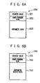
- Fig. 6A shows a configuration example of an arithmetic data file 200 to be transmitted from the PLC 2 to the general-purpose PC 7
- Fig. 6B shows a configuration example of an arithmetic result data file 700 to be transmitted from the general-purpose PC 7 to the PLC 2.
- the arithmetic data file 200 and the arithmetic result data file 700 are composed including counter values 201 and 701, hand-shaking flags 202 and 702, and real data (arithmetic data 203 and arithmetic result data 703), respectively.
- the hand-shaking flags 202 and 702 are for surely linking the sequence processing in the PLC 2 and the arithmetic processing in the general-purpose PC 7.
- the unique number is transmitted together with the arithmetic data at the time when the arithmetic data is transmitted from the PLC 2 to the general-purpose PC 7 (that is, the timing of starting the operation of the general-purpose PC 7) to latch the sequence processing.
- the latch is released and the sequence processing is advanced.
- the functions can be divided such that sequential control logic is executed by the PLC 2 and complicated arithmetic processing is executed by the general-purpose PC 7. This makes it possible to increase the accuracy and the speed of the plant control and to separate the development environments of software so as to improve the development efficiencies of software.
- the arithmetic result data outputted from the general-purpose PC 7 always passes through the PLC 2 so that the consistency of the arithmetic result data is checked in the PLC 2. Therefore, the reliability of the general-purpose PC 7 in the industrial application can be compensated, for example, in terms of punctuality. This makes it possible to secure the punctuality of the general-purpose PC 7 (general-purpose OS) in which the punctuality of the arithmetic processing is secured, so as to apply the general-purpose PC 7 to the plant control.
- Fig. 7 is a view explaining a usage example of the plant control system to which the present invention is applied.
- the PLC 2 is connected to an analysis PC 7a, a simulation PC 7b and a control PC 7c which are general purpose PCs.
- the three PCs 7a to 7c are illustrated as separate PCs for explaining the functions, but those may not be separate PCs.
- This example is an example of making, more efficient, development of the following steps: (1) task analysis, (2) development of a solution and off-line verification, (3) experimental manufacture, verification and evaluation, and (4) permanent use.
- the analysis PC 7a collects the process data from the steelmaking plant and synchronously replays image information from an industrial television (ITV) 8 monitoring the steelmaking plant to analyze the data in real time. Then, the data analyzed by the analysis PC 7a is inputted into the simulation PC 7b and subjected to data analysis at a higher level. Though the data is inputted into the general-purpose PC 7 from the steelmaking plant via the PLC 2 in the description of the above-described embodiment, the data may be directly inputted from the steelmaking plant for the purpose of collecting the process data. As a matter of course, process data selected by the PLC 2 may be inputted.
- a measure consideration model is performed as shown in a state (b) of Fig. 7 .
- the process data collected by the analysis PC 7a is compared to the simulation data simulated by the simulation PC 7b so that the simulation PC 7b performs the model verification by the simulation and verification by estimation of unpredictable data.
- a verification logic using a general-purpose PC easily programmed is created as shown in a state (c) of Fig. 7 .
- the simulation PC 7b is used to perform a parallel-running verification and to perform an actual device test and verification in cooperation with the PLC 2.
- the present invention has been described with the embodiment hereinabove.
- the present invention is not limited only to that embodiment, but may be modified within the scope of the present invention.
- the counter value which has been added to the arithmetic data that is the base of the arithmetic result data to be transmitted to the PLC 2 (namely, the same counter value)
- the counter values do not need be the same as long as time management information associated with the time management information which has been added to the arithmetic data that is the base can be added.
- the present invention is applicable to the case of controlling various kinds of plants for gas, food and medicine, chemical product, automobile, semiconductor and so on.
Description
- The present invention relates to a plant control system and method suitable for controlling, for example, a steelmaking plant.
- In a plant control system controlling, for example, a steelmaking plant, a LAN is often constructed with a process computer managing and controlling the steelmaking plant as an upper layer and a programmable logic controller interposed between the process computer and various kinds of equipment of the steelmaking plant and a DCS being an instrumentation controller as a lower layer. The programmable logic controller controls actuators of the manufacturing apparatus and acquires sensor information from sensors for performing process measurement of the temperature, pressure, speed and so on of manufacturing process according to the output from the process computer, so as to mainly take charge of real-time control at a high speed in a period of about several milliseconds to several hundreds of milliseconds.
- Patent Document 1: Japanese Laid-open Patent Publication No.
2000-137662 - Besides, the programmable logic controller has the reliability and stability secured for the operation but has a problem of a low development efficiency of software for complicated or large-scale arithmetic processing accompanied by convergent arithmetic and learning arithmetic. On the other hand, the arithmetic processing ability of the general-purpose personal computer and the ease of developing software are drastically improved due to the development of the recent computer technology. From the viewpoints, there are many advantages in that the general-purpose personal computer is introduced into the same layer on the plant control system as that of the programmable logic controller to take charge of the arithmetic processing.
- However, the general-purpose personal computer is superior in the arithmetic processing ability and the ease of developing software, but is inferior in reliability of punctuality and so on in the industrial application. Therefore, the general-purpose personal computer is in danger of causing a trouble when it is just connected to the various kinds of equipment of the steelmaking plant and controls them.
- Relating to this kind of technology, Patent Document 1 discloses that the programmable logic controller is not directly connected to the host computer but is connected to the host computer via a display device having an arithmetic processing ability and a data communication suitability higher than those of the programmable logic controller. In Patent Document 1, the display device performs protocol conversion so that programmable logic controllers can be controlled by a common program on the host computer side.
-
EP 0 800 126A discloses an information processing unit including a general-purpose personal computer and a sequence engine having a ladder interpreter connected to the general-purpose personal computer through an expansion bus, the ladder interpreter executing a sequence command on the basis of a predetermined sequence program requested by the general-purpose personal computer, and the general-purpose personal computer executing information processing on the basis of a predetermined information processing program and peripheral processing in accordance with a peripheral processing request from the ladder interpreter. -
DE 103 32 793A discloses a system for accessing a programmable logic controller (PLC) having at least a computer that is coupled to the PLC via a PLC interface, whereby the computer can make a read access to a first process image of the input signals to the PLC and a write access to a second process image of the output signals of the PLC. -
EP 1 693 725A discloses a development system for process control systems and corresponding method and computer program product, the system having a computer program loadable in a process close component of a process control system and another computer program is executable on a computer to control and/or manage a process that is designed to execute a real-time compatible program code of a standard algorithm for a controller on the computer, wherein the process replaces data with one of the programs that is residing in the system. - An object of the present invention is to introduce a high-speed or highly-functional information processor such as a general-purpose personal computer or the like into a plant control system so that functions to be processed are divided between the programmable logic controller and the information processor to suit their data processing abilities, and to compensate the reliability of the information processor in the industrial application, for example, in the operation timing between the apparatuses and equipment constituting a manufacturing plant, that is, in punctuality.
- To attain the above objects, a plant control system of the present invention includes: a process computer managing a plant; a programmable logic controller interposed between the process computer and equipment of the plant; and an information processor executing arithmetic processing based on arithmetic data received from the programmable logic controller and transmitting arithmetic result data thereof to the programmable logic controller, wherein the programmable logic controller includes a transmission processing unit extracting the arithmetic data from data inputted from the equipment of the plant into the programmable logic controller and transmitting the arithmetic data to the information processor; and a consistency check unit checking consistency with a predetermined reference for evaluating validity of the arithmetic result data received from the information processor.
- The plant control method of the present invention is a plant control method by a plant control system, the plant control system including: a process computer managing a plant; a programmable logic controller interposed between the process computer and equipment of the plant; and an information processor executing arithmetic processing based on arithmetic data received from the programmable logic controller and transmitting arithmetic result data thereof to the programmable logic controller, wherein the programmable logic controller executes a transmission processing procedure of extracting the arithmetic data from data inputted from the equipment of the plant into the programmable logic controller and transmitting the arithmetic data to the information processor; and a consistency check procedure of checking consistency with a predetermined reference for evaluating validity of the arithmetic result data received from the information processor.
- According to the present invention, the functions can be divided such that sequential control logic is executed by the programmable logic controller and complicated arithmetic processing is executed by the information processor such as the general-purpose personal computer or the like. This makes it possible to increase the accuracy and the speed of the plant control and to separate the development environments of software so as to improve the development efficiencies of software.
- In addition, the arithmetic result data outputted from the information processor always passes through the programmable logic controller so that the consistency of the arithmetic result data is checked in the programmable logic controller. Therefore, the reliability of the information processor in the industrial application can be compensated, for example, in terms of punctuality.
-
-
Fig. 1 is a view showing a schematic structure of a plant control system according to this embodiment; -
Fig. 2 is a block diagram showing functional configurations of a PLC and a general purpose PC according to this embodiment; -
Fig. 3 is a block diagram showing a hardware configuration example of the general-purpose PC according to this embodiment; -
Fig. 4 is a flowchart showing the processing operation in the PLC according to this embodiment; -
Fig. 5 is a flowchart showing the processing operation in the general-purpose PC according to this embodiment; -
Fig. 6A is an illustration showing a configuration example of an arithmetic data file to be transmitted from the PLC to the general-purpose PC according to this embodiment; -
Fig. 6B is an illustration showing a configuration example of an arithmetic result data file to be transmitted from the general-purpose PC to the PLC according to this embodiment; and -
Fig. 7 is a view explaining a usage example of the plant control system to which the present invention is applied. - Hereinafter, a preferred embodiment of the present invention will be described with reference to the accompanying drawings.
-
Fig. 1 shows a schematic structure of a plant control system according to this embodiment. In this embodiment, a steelmaking plant including iron and steel manufacturing facilities (a rolling plant including spindle, gear, shaft, motor and so on for driving a rolling mill roll for rolling a steel plate in the illustrated example) will be described as an example. - As shown in
Fig. 1 , a process computer 1 on an upper layer and a programmable logic controller (PLC) 2 on a lower layer constitute a LAN under Ethernet (registered trademark) standards in the plant control system. - The process computer 1 on the upper layer, which manages the steelmaking plant, for example, issues a manufacturing instruction to an operator based on a manufacturing plan, collects various kinds of sensor information, and transmits information necessary for control to the PLC 2.
- The PLC 2 on the lower layer, which is interposed between the process computer 1 and various kinds of equipment 3 (actuators, sensors and so on) of the steelmaking plant, controls the actuators according to the output from the process computer 1, acquires sensor information from the sensors, and so on. The PLC 2 on the lower layer mainly takes charge of real-time control at a high speed in a period of about several milliseconds to several hundreds of milliseconds.
- An input/output module (I/O) 4 such as an RIO or the like into/from which data is inputted/outputted when the PLC 2 communicates with the
equipment 3 of the steelmaking plant, a human-machine interface (HMI) 5 displaying various kinds of information such as the state and a work instruction relating to the steelmaking plant are included in the lower layer to constitute aLAN 6. Note that depending on the PLC 2, it may be directly connected to theequipment 3 of the steelmaking plant without passing through the input/output module (I/O) 4. - Further, a general-purpose personal computer (general-purpose PC) 7 is connected to the PLC 2 via the
LAN 6. The general-purpose PC 7 is a computer installed separately from the process computer 1 on the upper layer. The general-purpose PC 7, which mainly executes arithmetic processing necessary for real-time control based on arithmetic data received from the PLC 2 and transmits the arithmetic result data to the PLC 2, corresponds to the information processor in the present invention. InFig. 1 , the general-purpose PC 7 is also connected to the process computer 1, but the general-purpose PC 7 only needs to be connected at least to the PLC 2 in the present invention. - Note that though only one PLC 2 is shown in
Fig. 1 , a plurality of PLCs 2 can be of course connected to the process computer. - In addition, the general-
purpose PC 7 may be installed for each PLC 2, or may be shared among a plurality of PLCs 2. In the case where the general-purpose PC 7 is shared among the plural PLCs 2, for example, the general-purpose PC 7 may be configured to be able to perform integration arithmetic using arithmetic data received from one of the PLCs 2 and arithmetic data received from another of the PLCs 2 and transmit the arithmetic result data to both of the PLCs 2. - The PLC 2 here is a kind of a small-sized computer but is different from a standard computer in the way of operation, and uses, as the operation model, a state machine on the basis of a relay circuit as a prototype. The PLC 2 is not different from the standard computer in that it operates with software, but does not easily implement complicated arithmetic because it is programmed in a ladder language in many cases. However, the reliability and stability are ensured for the PLC 2 because it has been developed and used essentially for the industrial application for a long time.
- On the other hand, the general-purpose PC 7 uses the general-purpose operating system (OS) such as Windows (registered trademark) or the like and is superior in arithmetic processing ability and ease of developing software. However, the general-
purpose PC 7 is often inferior to the PLC in reliability in terms of punctuality (ensuring that information is transmitted within a predetermined control period) and so on in the industrial application. For example, depending on a complexity, the arithmetic processing time may vary. Further, the general-purpose PC 7 is not necessarily to be made for a continuous operation for a long time, and therefore may cause a failure such as hang-up and so on in 24-hour operation or the like. - In the plant control system to which the present invention is applied, functions to be processed are divided such that a sequential control logic (various kinds of judgment or the like) is executed by the PLC 2 and complicated arithmetic processing (numerical arithmetic such as convergence arithmetic or the like) is executed by the general-
purpose PC 7. In addition, the arithmetic result data outputted from the general-purpose PC 7 always passes through the PLC 2 so that the consistency of the arithmetic result data is checked in the PLC 2 to compensate the reliability of the general-purpose PC 7 in the industrial application, for example, in terms of punctuality. - Hereinafter, functional configurations of the PLC 2 and the general-
purpose PC 7 will be described with reference toFig. 2 . In thePLC 2, 21 denotes an input processing unit into which data is inputted from theequipment 3 of the steelmaking plant via the I/O 4. 22 denotes a main sequence processing unit which executes sequential control logic. - 23 denotes a fixed period clock processing unit which counts up in a fixed period T (for example, every 30 ms). 24 denotes a transmission processing unit which extracts predetermined arithmetic data from the data inputted into the PLC 2, typically, the data inputted from the
equipment 3 of the steelmaking plant, and transmits it to the general-purpose PC 7. Thetransmission processing unit 24 adds a counter value which is made by adding +1 every transmission of the arithmetic data, as the time management information in the present invention when transmitting the arithmetic data to the general-purpose PC 7. - 25 denotes a reception processing unit which receives the arithmetic result data from the general-
purpose PC 7. 26 denotes a consistency check unit which checks the consistency with a predetermined reference for evaluating the validity of the arithmetic result data received from the general-purpose PC 7 though it will be described later in detail. 27 denotes an output processing unit which outputs data (for example, the data processed by the mainsequence processing unit 22 and the arithmetic result data received by thereception processing unit 25 or data created by a simple arithmetic such as addition, subtraction, multiplication and division from the above-described data) to theequipment 3 of the steelmaking plant via the I/O 4. - In the general-
purpose PC application processing unit 72 has a countervalue setting unit 72a to just set and add the counter value, which has been added to the arithmetic data that is the base of the arithmetic result data, to the arithmetic result data to be transmitted to the PLC 2. 73 denotes a transmission processing unit which transmits the arithmetic result data to the PLC 2. -
Fig. 3 shows a hardware configuration example of the general-purpose PC 7. The general-purpose PC 7 is composed of aCPU 101 being a central processing unit controlling the whole apparatus, adisplay unit 102 displaying various input conditions, analysis results and so on, astorage unit 103 such as a hard disk or the like saving the analysis result and so on, a ROM (read only memory) 104 storing a control program, various application programs, data and so on, a RAM (random access memory) 105 being a working area used when theCPU 101 executes processing, and aninput unit 106 such as a keyboard, a mouse and so on. -
Fig. 4 is a flowchart showing the processing operation in the PLC 2. The PLC 2 executes the operations such as collection of data in the fixed period T and so on. Data is inputted into theinput processing unit 21 from theequipment 3 of the steelmaking plant via the I/O 4 (Step S41), and the mainsequence processing unit 22 executes the sequential control logic (Step S42). - In parallel with the main sequence processing at Step S42, the
transmission processing unit 24 extracts the predetermined arithmetic data from the data inputted from theequipment 3 of the steelmaking plant (Step S43). Thetransmission processing unit 24 then adds the counter value to the arithmetic data (Step S44), and transmits the arithmetic data to the general-purpose PC 7 (Step S45). It is assumed here that thetransmission processing unit 24 adds, for example, a count value X (X is an integer number) to the arithmetic data and transmits the resulting data to the general-purpose PC 7. - Afterward, when the
reception processing unit 25 receives the arithmetic result data from the general-purpose PC 7 (Step S46), theconsistency check unit 26 checks the consistency with the predetermined reference for evaluating the validity of the arithmetic result data (Step S47). - The check for the consistency at Step S47 will be described here. As has been described, in the general-
purpose PC 7, the same counter value as the counter value, which has been added to the arithmetic data that is the base of the arithmetic result data, is added to the arithmetic result data to be transmitted to the PLC 2. Accordingly, if the counter value added to the arithmetic result data received at Step S46 is X, the arithmetic result data corresponds to the arithmetic data which has been recently transmitted, so that the data can be judged to have constant periodic consistency (the fixed periodicity is maintained). - As a matter of course, it is unnecessary to set the transmission of the arithmetic data and the reception of the arithmetic result data in the same period, and the reception of the arithmetic result data even after lapse of several periods may be allowed depending on the kind of data, the contents of arithmetic and so on. More specifically, as long as the counter value added to the arithmetic result data received at Step S46 is X-n (n is a predetermined integer number), the arithmetic result data may be judged to have constant periodic consistency.
- Further, the consistencies such as whether the arithmetic result data received at Step S46 lies between predetermined upper/lower limit values, and whether the arithmetic result data has the same polarity (positive or negative) envisioned in the PLC 2, are also checked.
- When it is judged that there is no consistency as a result of the check for consistency at Step S47, for example, the arithmetic result data is not used but is discarded. Further, when the arithmetic result data corresponding to the arithmetic data is not returned in a long time, the operator may be notified of the fact because some abnormal condition could occur in the general-
purpose PC 7. - At Step S48, the
output unit 27 adds the arithmetic result data which has been judged to have the consistency by theconsistency check unit 26 or the data created by a simple arithmetic such as addition, subtraction, multiplication and division from the arithmetic result data, if existing, to the data processed by the mainsequence processing unit 22, and outputs the resulting data to theequipment 3 of the steelmaking plant via the I/O 4. - The above-described processing at Steps S41 to S48 is repeated in a fixed period T until an end instruction is issued (Step S49).
-
Fig. 5 is a flowchart showing the processing operation in the general-purpose PC 7. The general-purpose PC 7 operates by occurrence of an event asynchronously with the clock of the PLC 2. When thereception processing unit 71 receives the arithmetic data from the PLC 2 (Step S51), theapplication processing unit 72 executes the arithmetic processing (Step S52). Then, the countervalue setting unit 72a just sets and adds the counter value, which has been added to the arithmetic data that is the base of the arithmetic result data, to the arithmetic result data to be transmitted to the PLC 2 (Step S53), and thetransmission processing unit 73 transmits the arithmetic result data to the PLC 2 (Step S54). -
Fig. 6A shows a configuration example of an arithmetic data file 200 to be transmitted from the PLC 2 to the general-purpose PC 7, andFig. 6B shows a configuration example of an arithmetic result data file 700 to be transmitted from the general-purpose PC 7 to the PLC 2. The arithmetic data file 200 and the arithmetic result data file 700 are composed including counter values 201 and 701, hand-shakingflags arithmetic data 203 and arithmetic result data 703), respectively. - The hand-shaking
flags purpose PC 7. By adding an unique number to the operation at the time of sequence when the general-purpose PC 7 needs to operate in conjunction, the unique number is transmitted together with the arithmetic data at the time when the arithmetic data is transmitted from the PLC 2 to the general-purpose PC 7 (that is, the timing of starting the operation of the general-purpose PC 7) to latch the sequence processing. Then, using the number transmitted together with the arithmetic result data at the time of completion of the operation of the general-purpose PC 7, the latch is released and the sequence processing is advanced. - As described above, the functions can be divided such that sequential control logic is executed by the PLC 2 and complicated arithmetic processing is executed by the general-
purpose PC 7. This makes it possible to increase the accuracy and the speed of the plant control and to separate the development environments of software so as to improve the development efficiencies of software. - In addition, the arithmetic result data outputted from the general-
purpose PC 7 always passes through the PLC 2 so that the consistency of the arithmetic result data is checked in the PLC 2. Therefore, the reliability of the general-purpose PC 7 in the industrial application can be compensated, for example, in terms of punctuality. This makes it possible to secure the punctuality of the general-purpose PC 7 (general-purpose OS) in which the punctuality of the arithmetic processing is secured, so as to apply the general-purpose PC 7 to the plant control. -
Fig. 7 is a view explaining a usage example of the plant control system to which the present invention is applied. As shown inFig. 7 , the PLC 2 is connected to ananalysis PC 7a, asimulation PC 7b and acontrol PC 7c which are general purpose PCs. Note that the threePCs 7a to 7c are illustrated as separate PCs for explaining the functions, but those may not be separate PCs. This example is an example of making, more efficient, development of the following steps: (1) task analysis, (2) development of a solution and off-line verification, (3) experimental manufacture, verification and evaluation, and (4) permanent use. - As shown in a state (a) of
Fig. 7 , theanalysis PC 7a collects the process data from the steelmaking plant and synchronously replays image information from an industrial television (ITV) 8 monitoring the steelmaking plant to analyze the data in real time. Then, the data analyzed by theanalysis PC 7a is inputted into thesimulation PC 7b and subjected to data analysis at a higher level. Though the data is inputted into the general-purpose PC 7 from the steelmaking plant via the PLC 2 in the description of the above-described embodiment, the data may be directly inputted from the steelmaking plant for the purpose of collecting the process data. As a matter of course, process data selected by the PLC 2 may be inputted. - If some measures are necessary as a result of analysis, development and verification of a measure consideration model are performed as shown in a state (b) of
Fig. 7 . Specifically, the process data collected by theanalysis PC 7a is compared to the simulation data simulated by thesimulation PC 7b so that thesimulation PC 7b performs the model verification by the simulation and verification by estimation of unpredictable data. - Next, a verification logic using a general-purpose PC easily programmed is created as shown in a state (c) of
Fig. 7 . Then, thesimulation PC 7b is used to perform a parallel-running verification and to perform an actual device test and verification in cooperation with the PLC 2. - Next, as shown in a state (d) of
Fig. 7 , the logic for which the validity has been verified is applied to an actual apparatus via the PLC 2 (sharing is made such that I/L and the upper/lower limit check are performed by the PLC 2 and complicated model arithmetic is performed by the PC). - The present invention has been described with the embodiment hereinabove. The present invention is not limited only to that embodiment, but may be modified within the scope of the present invention. For example, though the counter value, which has been added to the arithmetic data that is the base of the arithmetic result data to be transmitted to the PLC 2 (namely, the same counter value), is just set and added to the arithmetic result data to be transmitted to the PLC 2, in the general-
purpose PC 7 in the above-described embodiment, the counter values do not need be the same as long as time management information associated with the time management information which has been added to the arithmetic data that is the base can be added. - Though the steelmaking plant including the iron and steel manufacturing facilities has been described as an example in the above embodiment, the present invention is applicable to the case of controlling various kinds of plants for gas, food and medicine, chemical product, automobile, semiconductor and so on.
Claims (4)
- A plant control system comprising:a process computer (1) configured to manage a plant;a programmable logic controller (2) interposed between said process computer (1) and equipment of the plant and configured to execute an operation in a fixed period; andan information processor (7) composed of a personal computer which is inferior in reliability in terms of punctuality as compared with said programmable logic controller (2) and configured to execute arithmetic processing based on arithmetic data received from said programmable logic controller (2) and transmit arithmetic result data thereof to said programmable logic controller (2),wherein said programmable logic controller comprises a transmission processing unit (24) configured to extract the arithmetic data from data inputted from the equipment of the plant into said programmable logic controller (2) and transmit the arithmetic data to said information processor; characterized in that the programmable logic controller (2) comprises a unit configured to add a counter value, which is counted up in every transmission of the arithmetic data, to the arithmetic data to be transmitted by the transmission processing unit,wherein said information processor (7) comprises a unit configured to add the same counter value as the counter value, which has been added to the arithmetic data being a base of the arithmetic result data, to the arithmetic result data to be transmitted to said programmable logic controller (2), andwherein said programmable logic controller comprises a consistency check unit (26) configured to examine whether or not the arithmetic result data corresponding to the transmitted arithmetic data is received within a predetermined time period, based on the counter value added to the arithmetic result data received from said information processor (7) and the counter value added to the arithmetic data which has been transmitted by the transmission processing unit for evaluating validity of the arithmetic result data received from said information processor (7).
- The plant control system according to claim 1, wherein said consistency check unit is configured to check consistency of at least any one of upper/lower limits and a polarity of the arithmetic result data received from said information processor (7).
- The plant control system according to claim 1,
wherein said programmable logic controller comprises a sequence processing unit adapted to execute sequential control logic, and
wherein, in said programmable logic controller, the transmission processing unit, the unit to add the counter value and the consistency check unit are adapted to execute in parallel with the sequence processing unit. - A plant control method by using a plant control system, the plant control system comprising:a process computer (1) managing a plant;a programmable logic controller (2) interposed between the process computer and equipment of the plant and configured to execute an operation in a fixed period; andan information processor (7) composed of a personal computer which is inferior in reliability in terms of punctuality as compared with said programmable logic controller (2) and configured for executing arithmetic processing based on arithmetic data received from the programmable logic controller (2) and transmitting arithmetic result data thereof to the programmable logic controller (2),characterized in that the programmable logic controller (2) executes a transmission processing procedure of extracting the arithmetic data from data inputted from the equipment of the plant into the programmable logic controller (2) and transmitting the arithmetic data together with a counter value, which is counted up in every transmission of the arithmetic data, as time management information to the information processor (7); and in that a consistency check unit (26) of said programmable logic controller (2) examines whether or not the arithmetic result data corresponding to the transmitted arithmetic data is received within a predetermined time period for evaluating validity of the arithmetic result data received from the information processor (7), the arithmetic result data being the result of adding the same counter value as the counter value which has been added to the arithmetic data being a base of the arithmetic result data to be transmitted to said programmable logic controller (2).
Applications Claiming Priority (2)
| Application Number | Priority Date | Filing Date | Title |
|---|---|---|---|
| JP2007262632A JP4383476B2 (en) | 2007-10-05 | 2007-10-05 | Plant control system and method |
| PCT/JP2008/068063 WO2009044864A1 (en) | 2007-10-05 | 2008-10-03 | Plant control system and method |
Publications (3)
| Publication Number | Publication Date |
|---|---|
| EP2196880A1 EP2196880A1 (en) | 2010-06-16 |
| EP2196880A4 EP2196880A4 (en) | 2014-04-23 |
| EP2196880B1 true EP2196880B1 (en) | 2016-11-30 |
Family
ID=40526286
Family Applications (1)
| Application Number | Title | Priority Date | Filing Date |
|---|---|---|---|
| EP08835525.0A Active EP2196880B1 (en) | 2007-10-05 | 2008-10-03 | Plant control system and method |
Country Status (7)
| Country | Link |
|---|---|
| US (1) | US8352787B2 (en) |
| EP (1) | EP2196880B1 (en) |
| JP (1) | JP4383476B2 (en) |
| KR (1) | KR101135274B1 (en) |
| CN (1) | CN101815972B (en) |
| BR (1) | BRPI0818404A2 (en) |
| WO (1) | WO2009044864A1 (en) |
Families Citing this family (12)
| Publication number | Priority date | Publication date | Assignee | Title |
|---|---|---|---|---|
| US8818757B2 (en) * | 2008-09-30 | 2014-08-26 | Rockwell Automation Technologies, Inc. | Modular object and host matching |
| JP5371674B2 (en) * | 2009-10-08 | 2013-12-18 | 東芝三菱電機産業システム株式会社 | Test equipment |
| CN101832090B (en) * | 2010-04-27 | 2011-12-21 | 北方工业大学 | Warehouse and automatic ventilation control system thereof |
| WO2012020468A1 (en) * | 2010-08-09 | 2012-02-16 | 東芝三菱電機産業システム株式会社 | Data retrieval system |
| WO2012131909A1 (en) * | 2011-03-29 | 2012-10-04 | 三菱電機株式会社 | Fault diagnosis device and fault diagnosis system for servo control device |
| CN102621922B (en) * | 2012-03-23 | 2015-05-27 | 上海板机电气制造有限公司 | Adhesive making control system |
| US8839664B2 (en) * | 2012-04-06 | 2014-09-23 | Siemens Energy, Inc. | Detection and classification of failures of power generating equipment during transient conditions |
| JP6160781B2 (en) * | 2015-05-27 | 2017-07-12 | 三菱電機株式会社 | Control device and data reproduction device |
| JP6524920B2 (en) * | 2016-01-08 | 2019-06-05 | 東芝三菱電機産業システム株式会社 | Inter-PLC communication data complementing apparatus, inter-PLC communication data complementing method and inter-PLC communication data complementing program |
| KR102046147B1 (en) | 2018-12-28 | 2019-11-18 | 플랜트에셋 주식회사 | The consistency examination method of engineering data of 3D CAD model for plant engineering |
| JP7132257B2 (en) * | 2020-02-04 | 2022-09-06 | 株式会社日立製作所 | control system |
| CN115210659A (en) * | 2021-02-04 | 2022-10-18 | 东芝三菱电机产业系统株式会社 | Operation auxiliary system for industrial plant |
Family Cites Families (37)
| Publication number | Priority date | Publication date | Assignee | Title |
|---|---|---|---|---|
| JPS61131134A (en) | 1984-11-30 | 1986-06-18 | Fujitsu Ltd | Response time supervisory system of data processing system |
| WO1990008988A1 (en) * | 1989-01-25 | 1990-08-09 | Hitachi, Ltd. | Method and apparatus for automatically generating control program for computer controlled systems |
| US5185708A (en) * | 1990-06-18 | 1993-02-09 | Ge Fanuc Automation North America, Inc. | Method for collecting data by a manufacturing process manager from a plurality of programmable logic controllers |
| US5453926A (en) * | 1994-05-25 | 1995-09-26 | Quad/Tech, Inc. | Touch screen system for a web folder |
| JPH08307442A (en) * | 1995-05-12 | 1996-11-22 | Toshiba Corp | Data transfer system |
| EP0800126B1 (en) * | 1995-09-26 | 2002-11-27 | Omron Corporation | Method and apparatus for information processing |
| KR100191024B1 (en) * | 1995-12-21 | 1999-06-15 | 이구택 | Data acquisition system in plc |
| JPH09179608A (en) * | 1995-12-22 | 1997-07-11 | Shimadzu Corp | Distributed controller |
| US6032203A (en) * | 1997-04-07 | 2000-02-29 | General Electric Company | System for interfacing between a plurality of processors having different protocols in switchgear and motor control center applications by creating description statements specifying rules |
| JP2000137662A (en) | 1998-10-30 | 2000-05-16 | Digital Electronics Corp | Controller |
| US6411863B1 (en) * | 1998-11-02 | 2002-06-25 | The Minster Machine Company | Auxiliary control system for use with programmable logic controller in a press machine |
| US7206646B2 (en) * | 1999-02-22 | 2007-04-17 | Fisher-Rosemount Systems, Inc. | Method and apparatus for performing a function in a plant using process performance monitoring with process equipment monitoring and control |
| US7474929B2 (en) * | 2000-01-20 | 2009-01-06 | Fisher-Rosemount Systems, Inc. | Enhanced tool for managing a process control network |
| AU4733601A (en) * | 2000-03-10 | 2001-09-24 | Cyrano Sciences Inc | Control for an industrial process using one or more multidimensional variables |
| EP1410195A4 (en) * | 2001-06-22 | 2008-03-19 | Wonderware Corp | A customizable system for creating supervisory process control and manufacturing information applications |
| DE10304706A1 (en) * | 2002-07-24 | 2004-02-05 | Kuka Roboter Gmbh | Control of a plant in which there are a number of different machine systems linked onto a data bus and using programmable controllers that store historical data |
| US20050004781A1 (en) * | 2003-04-21 | 2005-01-06 | National Gypsum Properties, Llc | System and method for plant management |
| JP2004350086A (en) * | 2003-05-23 | 2004-12-09 | Renesas Technology Corp | Communication control method |
| DE10332793A1 (en) * | 2003-07-18 | 2005-02-17 | Siemens Ag | Programmable logic controller access system, especially for program testing purposes, has a computer with read access to the PLC input signals and write access to its output signals |
| JP4115958B2 (en) * | 2004-03-26 | 2008-07-09 | 株式会社東芝 | Plant operation schedule optimization method and optimization system |
| US7685128B2 (en) * | 2004-06-10 | 2010-03-23 | International Business Machines Corporation | Remote access agent for caching in a SAN file system |
| US8595652B2 (en) * | 2004-09-29 | 2013-11-26 | Rockwell Automation Technologies, Inc. | System status visualization method and system |
| US20060069459A1 (en) * | 2004-09-29 | 2006-03-30 | Retlich Kevin A | Industrial control and monitoring system status visualization method and system |
| DE102005008136A1 (en) * | 2005-02-21 | 2006-08-24 | Siemens Ag | Development system for process control systems and associated method and computer program product |
| JP2007043256A (en) * | 2005-08-01 | 2007-02-15 | Calsonic Kansei Corp | Gateway apparatus |
| US20080012724A1 (en) * | 2006-01-30 | 2008-01-17 | Corcoran Kevin F | Power line communications module and method |
| US8656160B2 (en) * | 2006-06-21 | 2014-02-18 | Ebay Inc. | Computer system authentication using security indicator |
| CN101523317B (en) * | 2006-08-08 | 2011-09-21 | 西门子工业公司 | Devices, systems, and methods regarding a plc system fault |
| KR20090042951A (en) * | 2006-08-08 | 2009-05-04 | 지멘스 에너지 앤드 오토메이션 인코포레이티드 | Devices, systems, and methods regarding a plc |
| US7821220B2 (en) * | 2006-09-29 | 2010-10-26 | Rockwell Automation Technologies, Inc. | Motor having integral programmable logic controller |
| US7966151B2 (en) * | 2006-10-24 | 2011-06-21 | Ford Motor Company | Method for analyzing operation of a machine |
| US7894460B2 (en) * | 2007-07-26 | 2011-02-22 | Air Liquide Large Industries U.S. Lp | Programmable logic controller protocol converter |
| US20090043415A1 (en) * | 2007-08-06 | 2009-02-12 | Chevron U.S.A. Inc. | System and Method for Distributed Control of a Plant Process |
| US8195844B2 (en) * | 2007-09-20 | 2012-06-05 | Siemens Aktiengesellschaft | Systems, devices, and/or methods for managing communications |
| US20100076724A1 (en) * | 2008-09-23 | 2010-03-25 | Harold Lee Brown | Method for capturing and analyzing test result data |
| JP5196573B2 (en) * | 2009-01-05 | 2013-05-15 | パナソニック株式会社 | COMMUNICATION METHOD, COMMUNICATION DEVICE, AND COMMUNICATION SYSTEM |
| US8843221B2 (en) * | 2009-12-09 | 2014-09-23 | Comau Spa | Automation management system and method |
-
2007
- 2007-10-05 JP JP2007262632A patent/JP4383476B2/en active Active
-
2008
- 2008-10-03 BR BRPI0818404 patent/BRPI0818404A2/en not_active Application Discontinuation
- 2008-10-03 CN CN2008801102236A patent/CN101815972B/en active Active
- 2008-10-03 WO PCT/JP2008/068063 patent/WO2009044864A1/en active Application Filing
- 2008-10-03 KR KR1020107009851A patent/KR101135274B1/en active IP Right Grant
- 2008-10-03 US US12/677,176 patent/US8352787B2/en active Active
- 2008-10-03 EP EP08835525.0A patent/EP2196880B1/en active Active
Also Published As
| Publication number | Publication date |
|---|---|
| JP4383476B2 (en) | 2009-12-16 |
| JP2009093375A (en) | 2009-04-30 |
| CN101815972B (en) | 2012-09-05 |
| CN101815972A (en) | 2010-08-25 |
| EP2196880A1 (en) | 2010-06-16 |
| BRPI0818404A2 (en) | 2015-04-22 |
| KR20100061577A (en) | 2010-06-07 |
| WO2009044864A1 (en) | 2009-04-09 |
| US20100318199A1 (en) | 2010-12-16 |
| EP2196880A4 (en) | 2014-04-23 |
| US8352787B2 (en) | 2013-01-08 |
| KR101135274B1 (en) | 2012-04-12 |
Similar Documents
| Publication | Publication Date | Title |
|---|---|---|
| EP2196880B1 (en) | Plant control system and method | |
| EP3336638B1 (en) | Controller, control program, and control method | |
| US9869993B2 (en) | System and method for monitoring and/or diagnosing operation of a production line of an industrial plant | |
| EP3557354B1 (en) | Control device, control program, and control method | |
| US10591886B2 (en) | Control system, control program, and control method for device switching responsive to abnormality detection | |
| EP3540532B1 (en) | Control system and control method | |
| US20060142873A1 (en) | Method to increase the safety integrity level of a control system | |
| US10452033B2 (en) | Process control system | |
| KR19990083781A (en) | Web Monitoring System | |
| JP2018097839A (en) | Control device, control program and control method | |
| EP2960735A1 (en) | Programmable indicator | |
| US10890889B2 (en) | Method of monitoring and assessing the operation of an industrial installation driven by a programmable controller and equipment implementing said method | |
| CN101340357B (en) | Debugging simulation system and method for remote monitoring terminal of subway safe door system | |
| US11520302B2 (en) | Control system and control device | |
| KR20230032675A (en) | System for collecting data using computerized numerical control mother machine | |
| CN115176208A (en) | Control device, program, and control method | |
| TR2021008830U5 (en) | AN AUTOMATION SYSTEM DEVELOPED TO REALIZE THE AUTOMATIC CONTROL OF INDUSTRIAL FACILITIES | |
| CN106940540A (en) | Controller, the control of equipment and state monitoring method | |
| TW202316220A (en) | Control system, information processing method, and information processing device | |
| CN116339246A (en) | Integrated control system platform and implementation method thereof | |
| JP2023151936A (en) | Data collection device and program | |
| BG3446U1 (en) | Monitoring system for machinery performance |
Legal Events
| Date | Code | Title | Description |
|---|---|---|---|
| PUAI | Public reference made under article 153(3) epc to a published international application that has entered the european phase |
Free format text: ORIGINAL CODE: 0009012 |
|
| 17P | Request for examination filed |
Effective date: 20100303 |
|
| AK | Designated contracting states |
Kind code of ref document: A1 Designated state(s): AT BE BG CH CY CZ DE DK EE ES FI FR GB GR HR HU IE IS IT LI LT LU LV MC MT NL NO PL PT RO SE SI SK TR |
|
| AX | Request for extension of the european patent |
Extension state: AL BA MK RS |
|
| DAX | Request for extension of the european patent (deleted) | ||
| RAP1 | Party data changed (applicant data changed or rights of an application transferred) |
Owner name: NIPPON STEEL & SUMITOMO METAL CORPORATION |
|
| A4 | Supplementary search report drawn up and despatched |
Effective date: 20140325 |
|
| RIC1 | Information provided on ipc code assigned before grant |
Ipc: G05B 19/05 20060101AFI20140319BHEP Ipc: G05B 19/418 20060101ALI20140319BHEP |
|
| 17Q | First examination report despatched |
Effective date: 20150409 |
|
| GRAP | Despatch of communication of intention to grant a patent |
Free format text: ORIGINAL CODE: EPIDOSNIGR1 |
|
| INTG | Intention to grant announced |
Effective date: 20160530 |
|
| GRAS | Grant fee paid |
Free format text: ORIGINAL CODE: EPIDOSNIGR3 |
|
| GRAA | (expected) grant |
Free format text: ORIGINAL CODE: 0009210 |
|
| RIN1 | Information on inventor provided before grant (corrected) |
Inventor name: HOSHINO, TAKEO Inventor name: SORAO, KENJI |
|
| AK | Designated contracting states |
Kind code of ref document: B1 Designated state(s): AT BE BG CH CY CZ DE DK EE ES FI FR GB GR HR HU IE IS IT LI LT LU LV MC MT NL NO PL PT RO SE SI SK TR |
|
| REG | Reference to a national code |
Ref country code: CH Ref legal event code: EP Ref country code: GB Ref legal event code: FG4D |
|
| REG | Reference to a national code |
Ref country code: AT Ref legal event code: REF Ref document number: 850368 Country of ref document: AT Kind code of ref document: T Effective date: 20161215 |
|
| REG | Reference to a national code |
Ref country code: IE Ref legal event code: FG4D |
|
| REG | Reference to a national code |
Ref country code: DE Ref legal event code: R096 Ref document number: 602008047685 Country of ref document: DE |
|
| REG | Reference to a national code |
Ref country code: CH Ref legal event code: NV Representative=s name: E. BLUM AND CO. AG PATENT- UND MARKENANWAELTE , CH |
|
| PG25 | Lapsed in a contracting state [announced via postgrant information from national office to epo] |
Ref country code: LV Free format text: LAPSE BECAUSE OF FAILURE TO SUBMIT A TRANSLATION OF THE DESCRIPTION OR TO PAY THE FEE WITHIN THE PRESCRIBED TIME-LIMIT Effective date: 20161130 |
|
| REG | Reference to a national code |
Ref country code: LT Ref legal event code: MG4D |
|
| REG | Reference to a national code |
Ref country code: NL Ref legal event code: MP Effective date: 20161130 |
|
| PG25 | Lapsed in a contracting state [announced via postgrant information from national office to epo] |
Ref country code: LT Free format text: LAPSE BECAUSE OF FAILURE TO SUBMIT A TRANSLATION OF THE DESCRIPTION OR TO PAY THE FEE WITHIN THE PRESCRIBED TIME-LIMIT Effective date: 20161130 Ref country code: GR Free format text: LAPSE BECAUSE OF FAILURE TO SUBMIT A TRANSLATION OF THE DESCRIPTION OR TO PAY THE FEE WITHIN THE PRESCRIBED TIME-LIMIT Effective date: 20170301 Ref country code: NO Free format text: LAPSE BECAUSE OF FAILURE TO SUBMIT A TRANSLATION OF THE DESCRIPTION OR TO PAY THE FEE WITHIN THE PRESCRIBED TIME-LIMIT Effective date: 20170228 Ref country code: SE Free format text: LAPSE BECAUSE OF FAILURE TO SUBMIT A TRANSLATION OF THE DESCRIPTION OR TO PAY THE FEE WITHIN THE PRESCRIBED TIME-LIMIT Effective date: 20161130 |
|
| PG25 | Lapsed in a contracting state [announced via postgrant information from national office to epo] |
Ref country code: HR Free format text: LAPSE BECAUSE OF FAILURE TO SUBMIT A TRANSLATION OF THE DESCRIPTION OR TO PAY THE FEE WITHIN THE PRESCRIBED TIME-LIMIT Effective date: 20161130 Ref country code: PT Free format text: LAPSE BECAUSE OF FAILURE TO SUBMIT A TRANSLATION OF THE DESCRIPTION OR TO PAY THE FEE WITHIN THE PRESCRIBED TIME-LIMIT Effective date: 20170330 Ref country code: ES Free format text: LAPSE BECAUSE OF FAILURE TO SUBMIT A TRANSLATION OF THE DESCRIPTION OR TO PAY THE FEE WITHIN THE PRESCRIBED TIME-LIMIT Effective date: 20161130 Ref country code: PL Free format text: LAPSE BECAUSE OF FAILURE TO SUBMIT A TRANSLATION OF THE DESCRIPTION OR TO PAY THE FEE WITHIN THE PRESCRIBED TIME-LIMIT Effective date: 20161130 |
|
| PG25 | Lapsed in a contracting state [announced via postgrant information from national office to epo] |
Ref country code: NL Free format text: LAPSE BECAUSE OF FAILURE TO SUBMIT A TRANSLATION OF THE DESCRIPTION OR TO PAY THE FEE WITHIN THE PRESCRIBED TIME-LIMIT Effective date: 20161130 |
|
| PG25 | Lapsed in a contracting state [announced via postgrant information from national office to epo] |
Ref country code: CZ Free format text: LAPSE BECAUSE OF FAILURE TO SUBMIT A TRANSLATION OF THE DESCRIPTION OR TO PAY THE FEE WITHIN THE PRESCRIBED TIME-LIMIT Effective date: 20161130 Ref country code: DK Free format text: LAPSE BECAUSE OF FAILURE TO SUBMIT A TRANSLATION OF THE DESCRIPTION OR TO PAY THE FEE WITHIN THE PRESCRIBED TIME-LIMIT Effective date: 20161130 Ref country code: SK Free format text: LAPSE BECAUSE OF FAILURE TO SUBMIT A TRANSLATION OF THE DESCRIPTION OR TO PAY THE FEE WITHIN THE PRESCRIBED TIME-LIMIT Effective date: 20161130 Ref country code: EE Free format text: LAPSE BECAUSE OF FAILURE TO SUBMIT A TRANSLATION OF THE DESCRIPTION OR TO PAY THE FEE WITHIN THE PRESCRIBED TIME-LIMIT Effective date: 20161130 Ref country code: RO Free format text: LAPSE BECAUSE OF FAILURE TO SUBMIT A TRANSLATION OF THE DESCRIPTION OR TO PAY THE FEE WITHIN THE PRESCRIBED TIME-LIMIT Effective date: 20161130 |
|
| PG25 | Lapsed in a contracting state [announced via postgrant information from national office to epo] |
Ref country code: BE Free format text: LAPSE BECAUSE OF FAILURE TO SUBMIT A TRANSLATION OF THE DESCRIPTION OR TO PAY THE FEE WITHIN THE PRESCRIBED TIME-LIMIT Effective date: 20161130 Ref country code: BG Free format text: LAPSE BECAUSE OF FAILURE TO SUBMIT A TRANSLATION OF THE DESCRIPTION OR TO PAY THE FEE WITHIN THE PRESCRIBED TIME-LIMIT Effective date: 20170228 |
|
| REG | Reference to a national code |
Ref country code: DE Ref legal event code: R097 Ref document number: 602008047685 Country of ref document: DE |
|
| REG | Reference to a national code |
Ref country code: FR Ref legal event code: PLFP Year of fee payment: 10 |
|
| PLBE | No opposition filed within time limit |
Free format text: ORIGINAL CODE: 0009261 |
|
| STAA | Information on the status of an ep patent application or granted ep patent |
Free format text: STATUS: NO OPPOSITION FILED WITHIN TIME LIMIT |
|
| 26N | No opposition filed |
Effective date: 20170831 |
|
| PG25 | Lapsed in a contracting state [announced via postgrant information from national office to epo] |
Ref country code: SI Free format text: LAPSE BECAUSE OF FAILURE TO SUBMIT A TRANSLATION OF THE DESCRIPTION OR TO PAY THE FEE WITHIN THE PRESCRIBED TIME-LIMIT Effective date: 20161130 |
|
| PG25 | Lapsed in a contracting state [announced via postgrant information from national office to epo] |
Ref country code: MC Free format text: LAPSE BECAUSE OF FAILURE TO SUBMIT A TRANSLATION OF THE DESCRIPTION OR TO PAY THE FEE WITHIN THE PRESCRIBED TIME-LIMIT Effective date: 20161130 |
|
| REG | Reference to a national code |
Ref country code: IE Ref legal event code: MM4A |
|
| PG25 | Lapsed in a contracting state [announced via postgrant information from national office to epo] |
Ref country code: LU Free format text: LAPSE BECAUSE OF NON-PAYMENT OF DUE FEES Effective date: 20171003 |
|
| REG | Reference to a national code |
Ref country code: FR Ref legal event code: PLFP Year of fee payment: 11 |
|
| PG25 | Lapsed in a contracting state [announced via postgrant information from national office to epo] |
Ref country code: MT Free format text: LAPSE BECAUSE OF NON-PAYMENT OF DUE FEES Effective date: 20171003 |
|
| PG25 | Lapsed in a contracting state [announced via postgrant information from national office to epo] |
Ref country code: IE Free format text: LAPSE BECAUSE OF NON-PAYMENT OF DUE FEES Effective date: 20171003 |
|
| REG | Reference to a national code |
Ref country code: AT Ref legal event code: UEP Ref document number: 850368 Country of ref document: AT Kind code of ref document: T Effective date: 20161130 |
|
| REG | Reference to a national code |
Ref country code: DE Ref legal event code: R082 Ref document number: 602008047685 Country of ref document: DE Representative=s name: VOSSIUS & PARTNER PATENTANWAELTE RECHTSANWAELT, DE Ref country code: DE Ref legal event code: R081 Ref document number: 602008047685 Country of ref document: DE Owner name: NIPPON STEEL CORPORATION, JP Free format text: FORMER OWNER: NIPPON STEEL & SUMITOMO METAL CORP., TOKYO, JP |
|
| PG25 | Lapsed in a contracting state [announced via postgrant information from national office to epo] |
Ref country code: HU Free format text: LAPSE BECAUSE OF FAILURE TO SUBMIT A TRANSLATION OF THE DESCRIPTION OR TO PAY THE FEE WITHIN THE PRESCRIBED TIME-LIMIT; INVALID AB INITIO Effective date: 20081003 |
|
| PG25 | Lapsed in a contracting state [announced via postgrant information from national office to epo] |
Ref country code: CY Free format text: LAPSE BECAUSE OF NON-PAYMENT OF DUE FEES Effective date: 20161130 |
|
| PGFP | Annual fee paid to national office [announced via postgrant information from national office to epo] |
Ref country code: FR Payment date: 20190913 Year of fee payment: 12 |
|
| PGFP | Annual fee paid to national office [announced via postgrant information from national office to epo] |
Ref country code: FI Payment date: 20191009 Year of fee payment: 12 |
|
| PGFP | Annual fee paid to national office [announced via postgrant information from national office to epo] |
Ref country code: IT Payment date: 20191009 Year of fee payment: 12 |
|
| PG25 | Lapsed in a contracting state [announced via postgrant information from national office to epo] |
Ref country code: TR Free format text: LAPSE BECAUSE OF FAILURE TO SUBMIT A TRANSLATION OF THE DESCRIPTION OR TO PAY THE FEE WITHIN THE PRESCRIBED TIME-LIMIT Effective date: 20161130 |
|
| PGFP | Annual fee paid to national office [announced via postgrant information from national office to epo] |
Ref country code: AT Payment date: 20190925 Year of fee payment: 12 |
|
| PGFP | Annual fee paid to national office [announced via postgrant information from national office to epo] |
Ref country code: GB Payment date: 20191003 Year of fee payment: 12 |
|
| PG25 | Lapsed in a contracting state [announced via postgrant information from national office to epo] |
Ref country code: IS Free format text: LAPSE BECAUSE OF FAILURE TO SUBMIT A TRANSLATION OF THE DESCRIPTION OR TO PAY THE FEE WITHIN THE PRESCRIBED TIME-LIMIT Effective date: 20170330 |
|
| REG | Reference to a national code |
Ref country code: FI Ref legal event code: MAE |
|
| REG | Reference to a national code |
Ref country code: AT Ref legal event code: MM01 Ref document number: 850368 Country of ref document: AT Kind code of ref document: T Effective date: 20201003 |
|
| GBPC | Gb: european patent ceased through non-payment of renewal fee |
Effective date: 20201003 |
|
| PG25 | Lapsed in a contracting state [announced via postgrant information from national office to epo] |
Ref country code: FR Free format text: LAPSE BECAUSE OF NON-PAYMENT OF DUE FEES Effective date: 20201031 Ref country code: FI Free format text: LAPSE BECAUSE OF NON-PAYMENT OF DUE FEES Effective date: 20201003 |
|
| PG25 | Lapsed in a contracting state [announced via postgrant information from national office to epo] |
Ref country code: GB Free format text: LAPSE BECAUSE OF NON-PAYMENT OF DUE FEES Effective date: 20201003 Ref country code: AT Free format text: LAPSE BECAUSE OF NON-PAYMENT OF DUE FEES Effective date: 20201003 |
|
| PG25 | Lapsed in a contracting state [announced via postgrant information from national office to epo] |
Ref country code: IT Free format text: LAPSE BECAUSE OF NON-PAYMENT OF DUE FEES Effective date: 20201003 |
|
| PGFP | Annual fee paid to national office [announced via postgrant information from national office to epo] |
Ref country code: DE Payment date: 20230830 Year of fee payment: 16 Ref country code: CH Payment date: 20231102 Year of fee payment: 16 |