EP2197654B1 - Injection molding apparatus with replaceable gate insert - Google Patents
Injection molding apparatus with replaceable gate insert Download PDFInfo
- Publication number
- EP2197654B1 EP2197654B1 EP09717630.9A EP09717630A EP2197654B1 EP 2197654 B1 EP2197654 B1 EP 2197654B1 EP 09717630 A EP09717630 A EP 09717630A EP 2197654 B1 EP2197654 B1 EP 2197654B1
- Authority
- EP
- European Patent Office
- Prior art keywords
- nozzle
- chamber
- insert
- sidewall
- tip
- Prior art date
- Legal status (The legal status is an assumption and is not a legal conclusion. Google has not performed a legal analysis and makes no representation as to the accuracy of the status listed.)
- Active
Links
- 238000001746 injection moulding Methods 0.000 title claims description 12
- 239000012943 hotmelt Substances 0.000 claims description 12
- 239000011800 void material Substances 0.000 claims description 9
- 238000007789 sealing Methods 0.000 claims description 3
- 230000037431 insertion Effects 0.000 claims 1
- 238000003780 insertion Methods 0.000 claims 1
- 238000002347 injection Methods 0.000 description 12
- 239000007924 injection Substances 0.000 description 12
- 238000000034 method Methods 0.000 description 5
- 238000010102 injection blow moulding Methods 0.000 description 4
- 230000008569 process Effects 0.000 description 3
- 229910000760 Hardened steel Inorganic materials 0.000 description 2
- 238000010276 construction Methods 0.000 description 2
- 230000008602 contraction Effects 0.000 description 2
- 239000000155 melt Substances 0.000 description 2
- 238000000465 moulding Methods 0.000 description 2
- 229910000984 420 stainless steel Inorganic materials 0.000 description 1
- 230000009471 action Effects 0.000 description 1
- 230000008878 coupling Effects 0.000 description 1
- 238000010168 coupling process Methods 0.000 description 1
- 238000005859 coupling reaction Methods 0.000 description 1
- 230000000694 effects Effects 0.000 description 1
- 239000000463 material Substances 0.000 description 1
- 230000013011 mating Effects 0.000 description 1
- 230000002093 peripheral effect Effects 0.000 description 1
- 230000000750 progressive effect Effects 0.000 description 1
- 230000002035 prolonged effect Effects 0.000 description 1
- 238000009877 rendering Methods 0.000 description 1
- 230000008439 repair process Effects 0.000 description 1
- 230000000717 retained effect Effects 0.000 description 1
Images


Classifications
-
- B—PERFORMING OPERATIONS; TRANSPORTING
- B29—WORKING OF PLASTICS; WORKING OF SUBSTANCES IN A PLASTIC STATE IN GENERAL
- B29C—SHAPING OR JOINING OF PLASTICS; SHAPING OF MATERIAL IN A PLASTIC STATE, NOT OTHERWISE PROVIDED FOR; AFTER-TREATMENT OF THE SHAPED PRODUCTS, e.g. REPAIRING
- B29C45/00—Injection moulding, i.e. forcing the required volume of moulding material through a nozzle into a closed mould; Apparatus therefor
- B29C45/17—Component parts, details or accessories; Auxiliary operations
- B29C45/26—Moulds
- B29C45/27—Sprue channels ; Runner channels or runner nozzles
- B29C45/2701—Details not specific to hot or cold runner channels
- B29C45/2708—Gates
- B29C45/2711—Gate inserts
-
- B—PERFORMING OPERATIONS; TRANSPORTING
- B29—WORKING OF PLASTICS; WORKING OF SUBSTANCES IN A PLASTIC STATE IN GENERAL
- B29K—INDEXING SCHEME ASSOCIATED WITH SUBCLASSES B29B, B29C OR B29D, RELATING TO MOULDING MATERIALS OR TO MATERIALS FOR MOULDS, REINFORCEMENTS, FILLERS OR PREFORMED PARTS, e.g. INSERTS
- B29K2105/00—Condition, form or state of moulded material or of the material to be shaped
- B29K2105/25—Solid
- B29K2105/253—Preform
Definitions
- This invention relates to injection blow molding machines and, more particularly, to improvements in tooling for the injection molding station of such a machine.
- US 2007/141195 A1 relates to an injection molding apparatus having upper and lower mold halves that split along the center line of the parison cavity and the gate opening leading thereto.
- Each hot melt injection nozzle is received within a tubular insert cup having a reduced diameter tip that is seated within the gate opening.
- the cup is mounted to the lower mold half so as to remain secured thereto as the upper mold half opens and closes the mold.
- the base end of each nozzle has a swivel ball and socket relationship with the manifold block which supplies it with hot melt, while the tip end of each injection nozzle has a swivel ball and socket type interface with the interior front end of the insert cup, thus providing for dimensional variations in the parts of the tooling that arise during non-uniform thermal expansion and contraction thereof.
- the parison molding cavity at the injection molding station of a typical injection blow molding machine is formed in part by a pair of superimposed mold halves that split or separate along the center line of each gate opening and parison cavity.
- Hot melt injection nozzles have discharge tips that are seated in the gate openings.
- the upper mold halves are raised off the bottom mold halves, and the cores that carry the new parisons are then lifted and rotated out of the mold.
- a new set of cores is placed in the cavities of the bottom mold halves and the mold is closed, creating a diametrical sealing relationship between each nozzle tip and the wall of its gate opening and preparing the mold cavities to receive hot melt through the nozzles.
- Another problem with conventional tooling involves the start up procedure following prolonged shut down of the machine. Initially, the nozzles and the hot manifold block to which they are attached are disposed in a retracted position with the nozzles pulled back out of the mold. To begin the start up procedure, mounting bolts on a retainer block that attach each nozzle to the manifold block are intentionally loosened so that there is some slight freedom of movement of the nozzles relative to the manifold block. The manifold block and nozzles are then heated up to their operating temperature, while the mold cavities are maintained at their operating temperatures. Then, the manifold block and nozzles are pushed forward to properly seat the nozzle tips in their respective gate openings leading to the cavities.
- Figures 1-4 illustrate conventional machine parts at the injection molding station of a typical injection blow molding machine, as well as tooling in accordance with the present invention.
- the mold halves are designed to split and separate along the center line of the parison mold cavity and the gate opening leading thereto, as described more fully below.
- the machine parts include a lower plate-like die set member 10 secured to the bed of the machine (not shown), and an upper plate-like die set member 12 that overlies member 10 and is moveable by means not illustrated vertically toward and away from member 10 on upright guides 14.
- the tooling includes an elongated manifold block 16 that is secured to lower member 10 and has an inlet sprue 18 ( Fig. 4 ) that is disposed to receive hot molten plastic material from a source of supply (not shown).
- Such hot melt is directed through internal passages in manifold block 16 to a series of injection nozzles 20 that project forwardly from the front side of manifold block 16.
- nozzles 20 have at their base ends a ball and socket coupling relationship with the manifold block 16 in accordance with the principles set forth in U.S. Patent 6,726,467 assigned to the assignee of the present invention.
- each nozzle 20 has a generally spherical base 22 that is received by a concave swivel seat 24 in manifold block 16.
- the nozzle 20 is retained in its seat by a retainer block 26 that is bolted against the front face of manifold block 16 by a pair of long bolts 28.
- the back side of retainer block 26 has a concave face 30 that overlies spherical base 22 of nozzle 20 so as to permit nozzle 20 to swivel to a certain extent as may become necessary during molding operations.
- Nozzle 20 is also provided with a tip 35 at its front, discharge end.
- Nozzle tip 35 has a forwardly facing end face 37 that surrounds an outlet 39 from passage 32. End face 37 slopes rearwardly away from outlet 39 as a radially outermost edge 41 of tip 35 is approached, thereby rendering end face 37 generally convex.
- end face 37 is arcuate.
- the radius of curvature of end face 37 shares the same center point as the radius of curvature of spherical base 22.
- a continuous, circumferential groove 43 is formed in nozzle 20 between tip 35 and a main shank portion 45 of the nozzle for thermal purposes.
- Manifold block 16 with its nozzles 20 is moveable horizontally toward and away from additional tooling in the form of a series of parison molds 36, each of which includes an upper mold half 38 bolted to the upper member 12 and a lower mold half 40 bolted to the lower member 10.
- mold halves 38, 40 cooperatively form a parison cavity 42 that receives an elongated core 44 from the opposite side of the apparatus.
- injection nozzles 20 are disposed for injecting hot melt into the cavities 42.
- the nozzles 20 are withdrawn from between the upper and lower mold halves 38, 40.
- each pair of mold halves 38, 40 also cooperatively defines a gate passage 46 at the manifold end of cavity 42 that is of significantly reduced dimensions relative to cavity 42.
- Gate passage 46 leads to cavity 42 from an enlarged void or well 48 formed in the manifold side of mold 36 when the latter is closed.
- Well 48 has a front end wall 50 formed by corresponding end wall surfaces in upper and lower mold halves 38, 40.
- Well 48 also includes an annular sidewall 52 that is formed by corresponding sidewall surfaces of upper and lower mold halves 38, 40 when mold 36 is closed.
- the upper and lower sidewall surfaces are substantially identical to one another.
- Each lower mold half 40 supports a nozzle-receiving insert cup 56 that occupies the well 48 when the mold 36 is closed.
- Each insert cup 56 is tubular and hollow, having a relative large diameter, generally cylindrical body portion 58 presenting front and rear ends 57 and 59, respectively.
- a smaller diameter tip portion 60 projects forwardly from front end 57.
- Tip portion 60 is cylindrical throughout its length so as to provide a diametrical sealing fit with the surrounding sidewalls of gate passage 46 when mold 38 is closed as illustrated in Figs. 14 and 15 .
- Each insert cup 56 is held against rotation within well 48 by its own keeper 62.
- Each keeper 62 includes a relatively small washer 64 that is secured to lower mold half 40 by a screw 66.
- a peripheral portion of each washer 64 projects laterally into well 48 and is disposed to be received within a mating notch 68 in a rearwardly facing annular rear edge 70 of rear end 59 of insert cup 56.
- Body portion 58 has a nozzle-receiving chamber 72 therein that extends axially inwardly from open rear end 59.
- Chamber 72 has a relatively large diameter clearance sidewall 74 closest to rear end 59, a relatively smaller diameter locating sidewall 76 closest to front end 57, and a forwardly tapering guiding sidewall 78 intermediate sidewalls 74 and 76.
- Locating sidewall 76 is disposed at the radially outer extremity of a rearwardly facing front end wall 80 in chamber 72.
- End wall 80 is generally slightly concave and surrounds a centrally disposed opening 82 that leads to a flow passage 84 through tip 60.
- Body portion 58 of insert cup 56 has a cylindrical exterior sidewall 86 that corresponds in configuration with the sidewall 52 of well 48 and is only slightly smaller in diameter than sidewall 52 to adapt insert cup 56 to be snugly received within well 48.
- Front end 57 of body portion 58 presents a slightly convexly curved front face 88 that matches the curvature of front end wall 50 of well 48 so that front face 88 abuts end wall 50 when insert cup 56 is disposed within well 48.
- insert cup 56 is constructed from 420 stainless steel, while mold halves 38, 40 are constructed from P20 hardened steel and nozzle 20 is constructed from 4140 hardened steel. In accordance with the invention, insert cup 56 thus has a lower thermal conductivity than nozzle 20 and mold 36.
- nozzles 20 project forwardly into the chambers 72 of insert cups 56 with the front end faces 37 of nozzle tips 35 spaced slightly rearwardly away from front end wall 80 to define a relatively narrow void 90 as shown in Figs. 14 and 15 .
- the thickness of void 90 may vary, depending upon a number of factors, but will typically range from 0.00 inches to 0.010 inches.
- the radius of curvature of front end wall 80 is greater than that of front end face 37 and has its center point axially offset from the center point of the radius of curvature of end face 37 so that void 90 progressively increases in width as locating sidewall 76 and nozzle tip outer edge 41 are approached.
- the diameter of locating sidewall 76 is slightly greater than the diameter of nozzle tip 35 at edge 41 such that edge 41 does not seal against locating side wall 76 but is only confined thereby so as to locate nozzle outlet 39 in axial alignment with gate passage 46.
- melt As hot melt is supplied by manifold block 16 to each nozzle 20, the melt emanates from nozzle tip 35, flows across void 90, moves through passage 84 in insert tip 60, and enters cavity 42. A portion of the melt flow backfills toward the radially outer extremity of void 90 and becomes somewhat cooler than the main flow. This cooler melt solidifies and creates a seal between nozzle tip 35 and insert 56.
- upper mold half 3 8 lifts off lower mold half 40 with upper die set member 12, leaving behind insert cup 56 with nozzle 20 received therein.
- the new parison within cavity 42 on core 44 also remains behind. Core 44, with the parison thereon, is then raised and moved away from the lower mold half 40 to provide room for a new core 44.
- the new core is inserted into the lower mold half 40 and upper mold half 38 is then lowered into operating position, whereupon the injection cycle is repeated.
- gate passage 46 may require less frequent repair than in the past due to the fact that no nozzle tip is directly bearing against and wearing on the surfaces of the gate passage 46 as in prior constructions.
- nozzles 20 can realign and skew to the extent necessary to accommodate dimensional misalignment in the tooling caused by thermal differentials and otherwise.
- nozzle tips 35 simply swivel within locating sidewall 76 as may be necessary.
- the progressive widening of void 90 provides clearance for front nozzle face 37 to pivot relative to front end wall 80 during this process.
- the enlarged nature of clearance sidewall 74 relative to shank portion 45 of nozzle 20 provides clearance for shank portion 45 during this action.
- Such realignment is accomplished without in any way restricting the flow of hot melt through the nozzles and into the cavities of mold 36.
- nozzle tips 35 and insert cups 56 also provides significant time and labor savings during start up and shut down of the machine.
- the manifold block and nozzles were heated up to their operating temperatures and then inserted into the molds, which were also at their operating temperatures.
- the loose mounting bolts accommodated slight realignment of the nozzles as necessary for the particular seats involved, whereupon the bolts were retightened to retain the nozzles in such positions.
- shut down the nozzles were withdrawn and allowed to cool separately from the molds in order to prevent bind up or damage within the molds.
- nozzles 20 can simply remain fully inserted within their insert cups 56.
- nozzles 20 simply swivel as need be at both their base ends 22 and their tip ends 35.
- nozzles 20 can remain fully inserted within their insert cups 56 as all components of the tooling are brought up to their operating temperatures.
- the nozzles 20 can swivel at their opposite ends as need be to accommodate dimensional variations that arise.
Description
- This invention relates to injection blow molding machines and, more particularly, to improvements in tooling for the injection molding station of such a machine.
-
US 2007/141195 A1 relates to an injection molding apparatus having upper and lower mold halves that split along the center line of the parison cavity and the gate opening leading thereto. Each hot melt injection nozzle is received within a tubular insert cup having a reduced diameter tip that is seated within the gate opening. The cup is mounted to the lower mold half so as to remain secured thereto as the upper mold half opens and closes the mold. The base end of each nozzle has a swivel ball and socket relationship with the manifold block which supplies it with hot melt, while the tip end of each injection nozzle has a swivel ball and socket type interface with the interior front end of the insert cup, thus providing for dimensional variations in the parts of the tooling that arise during non-uniform thermal expansion and contraction thereof. - The parison molding cavity at the injection molding station of a typical injection blow molding machine is formed in part by a pair of superimposed mold halves that split or separate along the center line of each gate opening and parison cavity. Hot melt injection nozzles have discharge tips that are seated in the gate openings. To remove a set of newly formed parisons from the mold, the upper mold halves are raised off the bottom mold halves, and the cores that carry the new parisons are then lifted and rotated out of the mold. A new set of cores is placed in the cavities of the bottom mold halves and the mold is closed, creating a diametrical sealing relationship between each nozzle tip and the wall of its gate opening and preparing the mold cavities to receive hot melt through the nozzles.
- For a variety of reasons, it is difficult to maintain both the upper and lower mold halves at uniform temperatures at all times. Consequently, the upper and lower mold halves experience different degrees of expansion and contraction, and perfect alignment between upper and lower mold halves is rarely achieved. This condition is aggravated by the fact that the hot injection nozzles typically run at significantly higher temperatures than either of the mold halves.
- These thermal expansion and misalignment issues inherent in split parison cavity design typically produce wear and plastic leakage at the interface between the nozzle tip and the parison cavity. The typical fix involves replacing the nozzles and repairing the gate opening region where the interface occurs.
- Another problem with conventional tooling involves the start up procedure following prolonged shut down of the machine. Initially, the nozzles and the hot manifold block to which they are attached are disposed in a retracted position with the nozzles pulled back out of the mold. To begin the start up procedure, mounting bolts on a retainer block that attach each nozzle to the manifold block are intentionally loosened so that there is some slight freedom of movement of the nozzles relative to the manifold block. The manifold block and nozzles are then heated up to their operating temperature, while the mold cavities are maintained at their operating temperatures. Then, the manifold block and nozzles are pushed forward to properly seat the nozzle tips in their respective gate openings leading to the cavities. As the top mold halves are subsequently lowered against the bottom halves, the loose nozzles are engaged and realigned as need be by the lowering mold halves. Once the mold is fully closed, all of the bolts on every nozzle are retightened to secure the nozzles in their adjusted positions. Depending upon the number of mold cavities involved, this can be a laborious and time-consuming process. At shut down, the manifold and nozzles must be pulled away from the parison cavities to prevent the nozzles from binding up in the mold and/or becoming damaged as the mold halves and nozzles cool down at different rates.
- There is also a problem with leakage at the base end of each nozzle and the manifold block. The repeated impact from the upper mold half during closing of the mold and effects of significant temperature differentials, as well as loosening and retightening operations of the mounting blocks for the nozzles, necessarily result in leakage problems for the rear areas of the nozzle as well as the discharge tips.
-
-
Figure 1 is an isometric view of tooling that incorporates the principles of the present invention at the injection molding station of an injection blow molding machine, the cavity molds being illustrated in an open condition; -
Fig. 2 is an isometric view similar toFig. 1 with the cavity molds closed; -
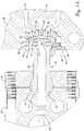
Fig. 3 is an isometric view similar toFigs. 1 and2 but with the top die set member and other components removed to reveal the manifold block and its injection nozzles; -
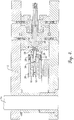
Fig. 4 is a vertical cross-sectional view through the tooling and machine components with the cavity molds closed; -
Fig. 5 is a fragmentary rear exploded view of the tooling; -
Fig. 6 is a fragmentary isometric view of the molds in an open condition illustrating how gate insert cups for receiving the injection nozzles remain with the bottom mold halves when the molds open; -
Fig. 7 is a fragmentary front exploded view of the tooling; -
Fig. 8 is a rear isometric view of an injection nozzle constructed in accordance with the principles of the present invention; -
Fig. 9 is a front isometric view thereof; -
Fig. 10 is a longitudinal cross-sectional view thereof; -
Fig. 11 is a rear isometric view of an insert cup constructed in accordance with the principles of the present invention; -
Fig. 12 is a front isometric view thereof; -
Fig. 13 is a longitudinal cross-sectional view thereof; -
Fig. 14 is an enlarged, fragmentary vertical cross-sectional view through one cavity of the tooling with the mold closed and the injection nozzle fully inserted into the insert cup; and -
Fig. 15 is a further enlarged view of the subject matter ofFig. 14 . - The present invention is susceptible of embodiment in many different forms, as defined by the scope of the appended claims. While the drawings illustrate and the specification describes certain preferred embodiments of the invention, it is to be understood that such disclosure is by way of example only. There is no intent to limit the principles of the present invention to the particular disclosed embodiments.
-
Figures 1-4 illustrate conventional machine parts at the injection molding station of a typical injection blow molding machine, as well as tooling in accordance with the present invention. In this type of machine, the mold halves are designed to split and separate along the center line of the parison mold cavity and the gate opening leading thereto, as described more fully below. - The machine parts include a lower plate-like die
set member 10 secured to the bed of the machine (not shown), and an upper plate-like dieset member 12 that overliesmember 10 and is moveable by means not illustrated vertically toward and away frommember 10 onupright guides 14. The tooling includes anelongated manifold block 16 that is secured tolower member 10 and has an inlet sprue 18 (Fig. 4 ) that is disposed to receive hot molten plastic material from a source of supply (not shown). Such hot melt is directed through internal passages inmanifold block 16 to a series ofinjection nozzles 20 that project forwardly from the front side ofmanifold block 16. Preferably,nozzles 20 have at their base ends a ball and socket coupling relationship with themanifold block 16 in accordance with the principles set forth inU.S. Patent 6,726,467 assigned to the assignee of the present invention. - Briefly described, and with reference also to
Figs. 5-15 , eachnozzle 20 has a generallyspherical base 22 that is received by a concaveswivel seat 24 inmanifold block 16. Thenozzle 20 is retained in its seat by aretainer block 26 that is bolted against the front face ofmanifold block 16 by a pair oflong bolts 28. The back side ofretainer block 26 has aconcave face 30 that overliesspherical base 22 ofnozzle 20 so as to permitnozzle 20 to swivel to a certain extent as may become necessary during molding operations. An axially extending throughpassage 32 innozzle 20 communicates with asupply passage 34 withinmanifold block 16 in all positions of swivelled movement ofnozzle 20 to provide for the discharge of hot melt fromnozzles 20 in all positions thereof. Nozzle 20 is also provided with atip 35 at its front, discharge end. -
Nozzle tip 35 has a forwardly facingend face 37 that surrounds anoutlet 39 frompassage 32.End face 37 slopes rearwardly away fromoutlet 39 as a radiallyoutermost edge 41 oftip 35 is approached, thereby renderingend face 37 generally convex. In a preferred embodiment,end face 37 is arcuate. Preferably also, but not necessarily, the radius of curvature ofend face 37 shares the same center point as the radius of curvature ofspherical base 22. A continuous,circumferential groove 43 is formed innozzle 20 betweentip 35 and amain shank portion 45 of the nozzle for thermal purposes. - Manifold
block 16 with itsnozzles 20 is moveable horizontally toward and away from additional tooling in the form of a series ofparison molds 36, each of which includes anupper mold half 38 bolted to theupper member 12 and alower mold half 40 bolted to thelower member 10. When eachmold 36 is closed,mold halves parison cavity 42 that receives anelongated core 44 from the opposite side of the apparatus. When themanifold block 16 is in its forward operating position as illustrated throughout the figures,injection nozzles 20 are disposed for injecting hot melt into thecavities 42. When manifold 16 is backed away from its forward position, thenozzles 20 are withdrawn from between the upper and lower mold halves 38, 40. - As illustrated particularly in
Figs. 14 and15 , each pair ofmold halves gate passage 46 at the manifold end ofcavity 42 that is of significantly reduced dimensions relative tocavity 42.Gate passage 46 leads tocavity 42 from an enlarged void or well 48 formed in the manifold side ofmold 36 when the latter is closed. Well 48 has afront end wall 50 formed by corresponding end wall surfaces in upper and lower mold halves 38, 40. Well 48 also includes anannular sidewall 52 that is formed by corresponding sidewall surfaces of upper and lower mold halves 38, 40 whenmold 36 is closed. The upper and lower sidewall surfaces are substantially identical to one another. - Each
lower mold half 40 supports a nozzle-receivinginsert cup 56 that occupies the well 48 when themold 36 is closed. Eachinsert cup 56 is tubular and hollow, having a relative large diameter, generallycylindrical body portion 58 presenting front andrear ends diameter tip portion 60 projects forwardly fromfront end 57.Tip portion 60 is cylindrical throughout its length so as to provide a diametrical sealing fit with the surrounding sidewalls ofgate passage 46 whenmold 38 is closed as illustrated inFigs. 14 and15 . - Each
insert cup 56 is held against rotation within well 48 by itsown keeper 62. Eachkeeper 62 includes a relativelysmall washer 64 that is secured tolower mold half 40 by ascrew 66. A peripheral portion of eachwasher 64 projects laterally into well 48 and is disposed to be received within amating notch 68 in a rearwardly facing annularrear edge 70 ofrear end 59 ofinsert cup 56. -
Body portion 58 has a nozzle-receivingchamber 72 therein that extends axially inwardly from openrear end 59.Chamber 72 has a relatively largediameter clearance sidewall 74 closest torear end 59, a relatively smallerdiameter locating sidewall 76 closest tofront end 57, and a forwardlytapering guiding sidewall 78intermediate sidewalls sidewall 76 is disposed at the radially outer extremity of a rearwardly facingfront end wall 80 inchamber 72.End wall 80 is generally slightly concave and surrounds a centrally disposedopening 82 that leads to aflow passage 84 throughtip 60. -
Body portion 58 ofinsert cup 56 has acylindrical exterior sidewall 86 that corresponds in configuration with thesidewall 52 of well 48 and is only slightly smaller in diameter thansidewall 52 to adaptinsert cup 56 to be snugly received within well 48.Front end 57 ofbody portion 58 presents a slightly convexly curvedfront face 88 that matches the curvature offront end wall 50 of well 48 so thatfront face 88 abutsend wall 50 wheninsert cup 56 is disposed within well 48. - In one preferred embodiment of the invention, insert
cup 56 is constructed from 420 stainless steel, while mold halves 38, 40 are constructed from P20 hardened steel andnozzle 20 is constructed from 4140 hardened steel. In accordance with the invention, insertcup 56 thus has a lower thermal conductivity thannozzle 20 andmold 36. - During injection molding operations,
nozzles 20 project forwardly into thechambers 72 of insert cups 56 with the front end faces 37 ofnozzle tips 35 spaced slightly rearwardly away fromfront end wall 80 to define a relativelynarrow void 90 as shown inFigs. 14 and15 . The thickness ofvoid 90 may vary, depending upon a number of factors, but will typically range from 0.00 inches to 0.010 inches. Preferably, the radius of curvature offront end wall 80 is greater than that offront end face 37 and has its center point axially offset from the center point of the radius of curvature of end face 37 so that void 90 progressively increases in width as locatingsidewall 76 and nozzle tipouter edge 41 are approached. Preferably also, the diameter of locatingsidewall 76 is slightly greater than the diameter ofnozzle tip 35 atedge 41 such thatedge 41 does not seal against locatingside wall 76 but is only confined thereby so as to locatenozzle outlet 39 in axial alignment withgate passage 46. - As hot melt is supplied by
manifold block 16 to eachnozzle 20, the melt emanates fromnozzle tip 35, flows acrossvoid 90, moves throughpassage 84 ininsert tip 60, and enterscavity 42. A portion of the melt flow backfills toward the radially outer extremity ofvoid 90 and becomes somewhat cooler than the main flow. This cooler melt solidifies and creates a seal betweennozzle tip 35 andinsert 56. At the completion of the injection cycle, upper mold half 3 8 lifts offlower mold half 40 with upper die setmember 12, leaving behindinsert cup 56 withnozzle 20 received therein. The new parison withincavity 42 oncore 44 also remains behind.Core 44, with the parison thereon, is then raised and moved away from thelower mold half 40 to provide room for anew core 44. The new core is inserted into thelower mold half 40 andupper mold half 38 is then lowered into operating position, whereupon the injection cycle is repeated. - As each
upper mold half 38 comes down into superimposed relationship withlower mold half 40,upper mold half 38 closes aboutinsert cup 56 without contactingnozzle 20. Thus, whileinsert cup 56 may become worn over time from repeated engagements with theupper mold half 38, the worn insert cup can be quickly and easily removed and replaced with a new cup. Moreover,gate passage 46 may require less frequent repair than in the past due to the fact that no nozzle tip is directly bearing against and wearing on the surfaces of thegate passage 46 as in prior constructions. - In this respect, it will be appreciated that the relationship between the
nozzles 20 and insert cups 56 is such thatnozzles 20 can realign and skew to the extent necessary to accommodate dimensional misalignment in the tooling caused by thermal differentials and otherwise. Thus, rather than binding up within thegate passages 46 or damaging such areas when misalignment and thermal conditions would otherwise tend to cause such,nozzle tips 35 simply swivel within locatingsidewall 76 as may be necessary. The progressive widening ofvoid 90 provides clearance forfront nozzle face 37 to pivot relative tofront end wall 80 during this process. Likewise, the enlarged nature ofclearance sidewall 74 relative toshank portion 45 ofnozzle 20 provides clearance forshank portion 45 during this action. Such realignment is accomplished without in any way restricting the flow of hot melt through the nozzles and into the cavities ofmold 36. - It will be appreciated that the swiveling relationship between
nozzle tips 35 and insert cups 56 also provides significant time and labor savings during start up and shut down of the machine. In prior constructions, it was typically necessary to pull the nozzles completely back out of the molds prior to start up. With the bolts of the mounting blocks for the nozzles loosened, the manifold block and nozzles were heated up to their operating temperatures and then inserted into the molds, which were also at their operating temperatures. As the nozzles seated themselves within the molds, the loose mounting bolts accommodated slight realignment of the nozzles as necessary for the particular seats involved, whereupon the bolts were retightened to retain the nozzles in such positions. At shut down, the nozzles were withdrawn and allowed to cool separately from the molds in order to prevent bind up or damage within the molds. - With the present invention, however, there is no need for this time-consuming process. Instead, at shut down the
nozzles 20 can simply remain fully inserted within their insert cups 56. As various parts of the tooling cool at non-uniform rates causing dimensional variations to arise,nozzles 20 simply swivel as need be at both their base ends 22 and their tip ends 35. At the other extreme, when the operation is started up,nozzles 20 can remain fully inserted within their insert cups 56 as all components of the tooling are brought up to their operating temperatures. Once again, thenozzles 20 can swivel at their opposite ends as need be to accommodate dimensional variations that arise.
Claims (5)
- Injection molding apparatus comprising:a hot melt distribution block (16),a hot melt discharge nozzle (20) secured to said block (16),said nozzle (20) having a base end (22) configured to permit the nozzle (20) to swivel with respect to the block,said nozzle (20) further having a discharge end comprising a nozzle tip (35),a mold (36) having a pair of opposed mold halves (38, 40) that cooperatively define, when the mold (36) is closed, a cavity (42) and a gate passage (46) leading to the cavity (42),at least one of said mold halves (38, 40) being movable away from the other mold half to open the mold (36) along a split line that longitudinally bisects the gate passage (46) and the cavity (42), anda tubular insert (56) mounted on one of said mold halves (38, 40) and having an insert tip (60) projecting into the gate passage (46) in sealing engagement with sidewalls thereof,said insert (56) having a chamber (72) disposed to receive the nozzle (20) for delivery of hot melt from the nozzle tip (35) into the cavity (42) through the insert tip (60),said chamber (72) having an end wall (80) surrounding an opening (82) into said insert tip (60),said chamber (72) further having an axially extending locating sidewall (76) at the radially outer limit of said end wall (80),said nozzle tip (35) having an end face (37) and an outer edge (41) confined radially by said locating sidewall (76) of the chamber (72) for locating the nozzle tip (35) in axial alignment with said opening (82) and permitting the nozzle tip (35) to swivel relative to the insert (56) during swiveling of the nozzle (20) relative to the block (16), whereby said insert (56) has a lower thermal conductivity than said nozzle (20) and said mold (36), characterized in that said end face (37) of the nozzle tip (35) is spaced away from said end wall (80) of the chamber (72) to define a void (90).
- Injection molding apparatus as claimed in claim 1, characterized in that said nozzle tip (35) is confined within said chamber (72) by contact of said outer edge (41) of the nozzle tip (35) against said locating sidewall (76) of the chamber (72), and said nozzle tip (35) is permitted to swivel relative to said insert (56) during swiveling of said nozzle (20) relative to said block.
- Injection molding apparatus as claimed in claim 2, characterized in thatsaid chamber (72) having a clearance sidewall (74) spaced axially from the locating sidewall (76) in a direction away from said end wall (80), andsaid clearance sidewall (74) being larger in diameter than said locating sidewall (76) to provide clearance between a shank (45) of the nozzle (20) and the insert (56) during swivelling of the nozzle (20) when the nozzle (20) is received within said chamber (72).
- Injection molding apparatus as claimed in claim 3, characterized in thatsaid chamber (72) having a tapering sidewall (78) interconnecting the clearance sidewall (74) and the locating sidewall (76) for guiding the nozzle (20) during insertion of the nozzle (20) into the insert (56).
- Injection molding apparatus as claimed in claim 1, characterized in that said end wall (80) of the chamber (72) and said end face (37) of the nozzle tip (35) are curved, and the radius of curvature of said end wall (80) is greater than the radius of curvature of the end face (37) so as to present a void (90) that progressively increases in width as the locating sidewall (76) of said chamber (72) and the outer edge (41) of said nozzle tip (35) are approached.
Applications Claiming Priority (2)
| Application Number | Priority Date | Filing Date | Title |
|---|---|---|---|
| US12/041,467 US7771189B2 (en) | 2008-03-03 | 2008-03-03 | Injection molding apparatus with replaceable gate insert |
| PCT/US2009/030317 WO2009111091A1 (en) | 2008-03-03 | 2009-01-07 | Injection molding apparatus with replaceable gate insert |
Publications (3)
| Publication Number | Publication Date |
|---|---|
| EP2197654A1 EP2197654A1 (en) | 2010-06-23 |
| EP2197654A4 EP2197654A4 (en) | 2012-11-28 |
| EP2197654B1 true EP2197654B1 (en) | 2017-05-10 |
Family
ID=41013359
Family Applications (1)
| Application Number | Title | Priority Date | Filing Date |
|---|---|---|---|
| EP09717630.9A Active EP2197654B1 (en) | 2008-03-03 | 2009-01-07 | Injection molding apparatus with replaceable gate insert |
Country Status (3)
| Country | Link |
|---|---|
| US (1) | US7771189B2 (en) |
| EP (1) | EP2197654B1 (en) |
| WO (1) | WO2009111091A1 (en) |
Families Citing this family (4)
| Publication number | Priority date | Publication date | Assignee | Title |
|---|---|---|---|---|
| US8475157B2 (en) | 2011-01-25 | 2013-07-02 | R&D Tool & Engineering Co. | Injection nozzle with enhanced heat transfer characteristics |
| US9597831B2 (en) * | 2014-06-27 | 2017-03-21 | R&D Tool & Engineering Co. | Blow molding tooling for high cavitation applications |
| US9272453B1 (en) | 2014-08-29 | 2016-03-01 | Husky Injection Molding Systems Ltd. | Hot runner with removable gate pad |
| EP3894161A4 (en) * | 2018-12-11 | 2022-09-07 | Husky Injection Molding Systems Luxembourg IP Development S.à.r.l | Molds, mold assemblies and stack components |
Family Cites Families (51)
| Publication number | Priority date | Publication date | Assignee | Title |
|---|---|---|---|---|
| US2814831A (en) | 1955-12-27 | 1957-12-03 | Dow Chemical Co | Injection molding apparatus |
| US3535742A (en) | 1967-07-31 | 1970-10-27 | Paul Marcus | Molding apparatus valve and nozzle |
| US3512216A (en) | 1968-03-26 | 1970-05-19 | Bischoff Chemical Corp | Injection molding nozzle support |
| US3559245A (en) | 1968-04-02 | 1971-02-02 | George R Ryan | Molding apparatus |
| US3718166A (en) | 1970-10-02 | 1973-02-27 | Midland Ross Corp | Manifold and adjustable nozzle assembly for molding machines |
| US3758252A (en) | 1971-11-08 | 1973-09-11 | A Kohler | Nozzle head assembly for injection mold |
| US3940226A (en) | 1973-07-02 | 1976-02-24 | Werner Lehara, Inc. | Apparatus for dispensing dough in a pattern utilizing moveable nozzles |
| US4076475A (en) | 1974-10-29 | 1978-02-28 | Trueblood, Inc. | Pressure injection machine and method |
| US4299791A (en) | 1979-07-18 | 1981-11-10 | Katashi Aoki | Method for the prevention of drooling from a plastic injection molding mold and injection nozzles |
| HU184903B (en) * | 1981-11-20 | 1984-11-28 | Reanal Finomvegyszergyar | Paint composition for biopsy examinations |
| US4416608A (en) | 1982-10-13 | 1983-11-22 | Owens-Illinois, Inc. | Apparatus for forming parisons |
| US4595552A (en) | 1984-12-13 | 1986-06-17 | Adolph Coors Company | Injection mold gate apparatus |
| US4751037A (en) | 1986-03-21 | 1988-06-14 | Daniel Faneuf | Injection molding process with movable mold core and injection nozzle assembly |
| CA1265907A (en) * | 1987-02-17 | 1990-02-20 | Jobst U. Gellert | Injection molding system having manifold with side mounted nozzles and method |
| CA1266358A (en) * | 1987-10-16 | 1990-03-06 | Jobst Ulrich Gellert | Injection molding system having clamped rotatable nozzles and method |
| US5254305A (en) | 1987-12-10 | 1993-10-19 | Otto Hofstetter Ag | Injection nozzle and method for charging an injection nozzle |
| DE3833868A1 (en) | 1988-10-05 | 1990-04-12 | Hofstetter Ag Otto | METHOD FOR INJECTION MOLDING PET SHAPES AND GATE SYSTEM |
| CA1274369A (en) * | 1989-02-28 | 1990-09-25 | Jobst Ulrich Gellert | Injection molding nozzle with self-supporting actuating mechanism |
| CA2008171C (en) * | 1990-01-19 | 1997-05-20 | Jobst Ulrich Gellert | Method of making a selected size injection molding nozzle |
| US5000675A (en) * | 1990-02-09 | 1991-03-19 | Mold-Masters Limited | Injection molding manifold and nozzle having laterally clamped flanges |
| JP2627814B2 (en) | 1990-09-20 | 1997-07-09 | ファナック株式会社 | Injection molding machine with display |
| US5374182A (en) | 1992-09-30 | 1994-12-20 | Husky Injection Molding Systems Ltd. | Hot runner manifold bushing |
| DE4313473C2 (en) | 1993-03-20 | 1996-12-19 | Karl Hehl | Closing unit for an injection molding machine |
| US5299928A (en) | 1993-07-26 | 1994-04-05 | Gellert Jobst U | Two-piece injection molding nozzle seal |
| US5443381A (en) | 1994-07-18 | 1995-08-22 | Gellert; Jobst U. | Injection molding one-piece insert having cooling chamber with radial rib portions |
| US5522720A (en) | 1994-10-24 | 1996-06-04 | Husky Injection Molding Systems Ltd. | Injector nozzle with pivotally movable surfaces |
| US5533882A (en) | 1994-11-29 | 1996-07-09 | Husky Injection Molding Systems Ltd. | Hot runner valve gated system |
| US5635227A (en) | 1995-06-07 | 1997-06-03 | R & D Tool And Engineering, Inc. | Replaceable air cylinder unit and valve gate for injection molding machines |
| US5716540A (en) | 1996-02-09 | 1998-02-10 | Johnson & Johnson Vision Products, Inc. | Apparatus and method for producing center gated lens molds for contact lens manufacture |
| CA2175634C (en) | 1996-05-02 | 2007-08-21 | Klaus Bauer | Injection molding valve member with head and neck portions |
| US5919430A (en) | 1996-06-19 | 1999-07-06 | Degussa Aktiengesellschaft | Preparation of crystalline microporous and mesoporous metal silicates, products produced thereby and use thereof |
| US5879727A (en) | 1997-01-21 | 1999-03-09 | Husky Injection Molding Systems, Ltd. | Insulated modular injection nozzle system |
| ID24359A (en) | 1997-05-16 | 2000-07-13 | Unilever Nv | PROCESS FOR PRODUCING A DETERGENT COMPOSITION |
| US5980234A (en) | 1998-04-29 | 1999-11-09 | R & D Tool & Engineering Co., | Blow mold apparatus for minimal gate |
| US6305923B1 (en) | 1998-06-12 | 2001-10-23 | Husky Injection Molding Systems Ltd. | Molding system using film heaters and/or sensors |
| US6261084B1 (en) | 1998-08-28 | 2001-07-17 | Synventive Moldings Solutions Canada, Inc. | Elastically deformable nozzle for injection molding |
| CA2262175C (en) | 1999-02-16 | 2008-02-12 | Mold-Masters Limited | Injection molding apparatus with removable nozzle seal |
| US6245278B1 (en) | 1999-06-03 | 2001-06-12 | Husky Injection Molding Systems Ltd. | Injection nozzle and method |
| US6264460B1 (en) | 1999-12-09 | 2001-07-24 | Pechiney Emballage Flexible Europe | Injection gate insulating and cooling apparatus |
| DE10024625B4 (en) * | 2000-05-18 | 2010-12-23 | Mht Mold & Hotrunner Technology Ag | Mold nest for plastics processing |
| US6394785B1 (en) * | 2000-11-20 | 2002-05-28 | Top Grade Molds Ltd. | Nozzle for injection mold |
| JP4221545B2 (en) | 2001-01-05 | 2009-02-12 | 信越化学工業株式会社 | Silicone rubber adhesive composition, integral molded body of silicone rubber and thermoplastic resin, and method for producing the same |
| JP3875851B2 (en) | 2001-04-20 | 2007-01-31 | 日精エー・エス・ビー機械株式会社 | Preform molding equipment |
| ITRM20010693A1 (en) | 2001-11-26 | 2003-05-26 | Sipa Spa | IMPROVEMENT IN PLASTIC INJECTION MOLDING MACHINES AND RELATED IMPLEMENTATION PROCESS. |
| JP3872022B2 (en) | 2002-03-05 | 2007-01-24 | 株式会社名機製作所 | Injection compression molding apparatus and injection compression molding die |
| US6726467B1 (en) | 2002-10-16 | 2004-04-27 | R&D Tool & Engineering Co. | Injection molding nozzle |
| US6923638B2 (en) | 2003-01-03 | 2005-08-02 | R & D Tool & Engineering Co. | Apparatus for obtaining balanced flow of hot melt in a distribution manifold |
| US6722011B1 (en) | 2003-05-09 | 2004-04-20 | Bradley Bacon | Apparatus and method for installing a c-clip |
| US7381050B2 (en) * | 2004-10-20 | 2008-06-03 | Mold-Masters (2007) Limited | Snap on flange for injection molding nozzle |
| US7704069B2 (en) | 2005-12-20 | 2010-04-27 | R&D Tool & Engineering Co. | Injection molding apparatus having swiveling nozzles |
| US7566216B2 (en) * | 2007-04-29 | 2009-07-28 | Husky Injection Molding Systems Ltd. | Mold assembly using inserts |
-
2008
- 2008-03-03 US US12/041,467 patent/US7771189B2/en active Active
-
2009
- 2009-01-07 EP EP09717630.9A patent/EP2197654B1/en active Active
- 2009-01-07 WO PCT/US2009/030317 patent/WO2009111091A1/en active Application Filing
Also Published As
| Publication number | Publication date |
|---|---|
| WO2009111091A1 (en) | 2009-09-11 |
| US20090220634A1 (en) | 2009-09-03 |
| EP2197654A1 (en) | 2010-06-23 |
| EP2197654A4 (en) | 2012-11-28 |
| US7771189B2 (en) | 2010-08-10 |
Similar Documents
| Publication | Publication Date | Title |
|---|---|---|
| EP1963073B1 (en) | Insert cup for a mold and injection apparatus comprising the same | |
| CN101687350B (en) | Mold assembly using inserts | |
| US8714965B2 (en) | Injection nozzle with enhanced heat transfer characteristics | |
| US7025586B2 (en) | Valve pin guidance and alignment system for an injection molding apparatus | |
| EP2180989B1 (en) | A compensating mold stack | |
| US7628605B2 (en) | Mold stack | |
| CN101873916B (en) | Compensating core for use with molding system and the molding system incorporating same | |
| US7364131B2 (en) | Non-return valve for use in a molding system | |
| EP2197654B1 (en) | Injection molding apparatus with replaceable gate insert | |
| CA2686630C (en) | A compensating retaining member for use with a molding system and the molding system incorporating same | |
| EP1578581B1 (en) | Injection molding nozzle | |
| US20160059458A1 (en) | Hot runner with removable gate pad | |
| CN103507226A (en) | Valve bushing for an injection molding apparatus | |
| CN100542777C (en) | Injection device | |
| CN111086153B (en) | Automobile thick-wall automobile logo and injection molding process | |
| US20120319334A1 (en) | Internal gas pressure method for producing plastic parts | |
| WO2022211136A1 (en) | Casting mold | |
| JP3047382B2 (en) | Valve gate device for injection molding die and valve gate forming method | |
| JPH0664833U (en) | Injection mold equipment |
Legal Events
| Date | Code | Title | Description |
|---|---|---|---|
| PUAI | Public reference made under article 153(3) epc to a published international application that has entered the european phase |
Free format text: ORIGINAL CODE: 0009012 |
|
| 17P | Request for examination filed |
Effective date: 20100331 |
|
| AK | Designated contracting states |
Kind code of ref document: A1 Designated state(s): AT BE BG CH CY CZ DE DK EE ES FI FR GB GR HR HU IE IS IT LI LT LU LV MC MK MT NL NO PL PT RO SE SI SK TR |
|
| AX | Request for extension of the european patent |
Extension state: AL BA RS |
|
| DAX | Request for extension of the european patent (deleted) | ||
| A4 | Supplementary search report drawn up and despatched |
Effective date: 20121026 |
|
| RIC1 | Information provided on ipc code assigned before grant |
Ipc: B29C 45/27 20060101ALI20121022BHEP Ipc: B29C 49/00 20060101AFI20121022BHEP |
|
| 17Q | First examination report despatched |
Effective date: 20150819 |
|
| GRAP | Despatch of communication of intention to grant a patent |
Free format text: ORIGINAL CODE: EPIDOSNIGR1 |
|
| INTG | Intention to grant announced |
Effective date: 20161208 |
|
| GRAS | Grant fee paid |
Free format text: ORIGINAL CODE: EPIDOSNIGR3 |
|
| GRAA | (expected) grant |
Free format text: ORIGINAL CODE: 0009210 |
|
| AK | Designated contracting states |
Kind code of ref document: B1 Designated state(s): AT BE BG CH CY CZ DE DK EE ES FI FR GB GR HR HU IE IS IT LI LT LU LV MC MK MT NL NO PL PT RO SE SI SK TR |
|
| REG | Reference to a national code |
Ref country code: GB Ref legal event code: FG4D |
|
| REG | Reference to a national code |
Ref country code: AT Ref legal event code: REF Ref document number: 891836 Country of ref document: AT Kind code of ref document: T Effective date: 20170515 Ref country code: CH Ref legal event code: EP |
|
| REG | Reference to a national code |
Ref country code: IE Ref legal event code: FG4D |
|
| REG | Reference to a national code |
Ref country code: DE Ref legal event code: R096 Ref document number: 602009045984 Country of ref document: DE |
|
| REG | Reference to a national code |
Ref country code: NL Ref legal event code: FP |
|
| REG | Reference to a national code |
Ref country code: LT Ref legal event code: MG4D |
|
| REG | Reference to a national code |
Ref country code: AT Ref legal event code: MK05 Ref document number: 891836 Country of ref document: AT Kind code of ref document: T Effective date: 20170510 |
|
| PG25 | Lapsed in a contracting state [announced via postgrant information from national office to epo] |
Ref country code: LT Free format text: LAPSE BECAUSE OF FAILURE TO SUBMIT A TRANSLATION OF THE DESCRIPTION OR TO PAY THE FEE WITHIN THE PRESCRIBED TIME-LIMIT Effective date: 20170510 Ref country code: FI Free format text: LAPSE BECAUSE OF FAILURE TO SUBMIT A TRANSLATION OF THE DESCRIPTION OR TO PAY THE FEE WITHIN THE PRESCRIBED TIME-LIMIT Effective date: 20170510 Ref country code: ES Free format text: LAPSE BECAUSE OF FAILURE TO SUBMIT A TRANSLATION OF THE DESCRIPTION OR TO PAY THE FEE WITHIN THE PRESCRIBED TIME-LIMIT Effective date: 20170510 Ref country code: GR Free format text: LAPSE BECAUSE OF FAILURE TO SUBMIT A TRANSLATION OF THE DESCRIPTION OR TO PAY THE FEE WITHIN THE PRESCRIBED TIME-LIMIT Effective date: 20170811 Ref country code: AT Free format text: LAPSE BECAUSE OF FAILURE TO SUBMIT A TRANSLATION OF THE DESCRIPTION OR TO PAY THE FEE WITHIN THE PRESCRIBED TIME-LIMIT Effective date: 20170510 Ref country code: HR Free format text: LAPSE BECAUSE OF FAILURE TO SUBMIT A TRANSLATION OF THE DESCRIPTION OR TO PAY THE FEE WITHIN THE PRESCRIBED TIME-LIMIT Effective date: 20170510 Ref country code: NO Free format text: LAPSE BECAUSE OF FAILURE TO SUBMIT A TRANSLATION OF THE DESCRIPTION OR TO PAY THE FEE WITHIN THE PRESCRIBED TIME-LIMIT Effective date: 20170810 |
|
| PG25 | Lapsed in a contracting state [announced via postgrant information from national office to epo] |
Ref country code: LV Free format text: LAPSE BECAUSE OF FAILURE TO SUBMIT A TRANSLATION OF THE DESCRIPTION OR TO PAY THE FEE WITHIN THE PRESCRIBED TIME-LIMIT Effective date: 20170510 Ref country code: IS Free format text: LAPSE BECAUSE OF FAILURE TO SUBMIT A TRANSLATION OF THE DESCRIPTION OR TO PAY THE FEE WITHIN THE PRESCRIBED TIME-LIMIT Effective date: 20170910 Ref country code: BG Free format text: LAPSE BECAUSE OF FAILURE TO SUBMIT A TRANSLATION OF THE DESCRIPTION OR TO PAY THE FEE WITHIN THE PRESCRIBED TIME-LIMIT Effective date: 20170810 Ref country code: SE Free format text: LAPSE BECAUSE OF FAILURE TO SUBMIT A TRANSLATION OF THE DESCRIPTION OR TO PAY THE FEE WITHIN THE PRESCRIBED TIME-LIMIT Effective date: 20170510 Ref country code: PL Free format text: LAPSE BECAUSE OF FAILURE TO SUBMIT A TRANSLATION OF THE DESCRIPTION OR TO PAY THE FEE WITHIN THE PRESCRIBED TIME-LIMIT Effective date: 20170510 |
|
| REG | Reference to a national code |
Ref country code: FR Ref legal event code: PLFP Year of fee payment: 10 |
|
| PG25 | Lapsed in a contracting state [announced via postgrant information from national office to epo] |
Ref country code: CZ Free format text: LAPSE BECAUSE OF FAILURE TO SUBMIT A TRANSLATION OF THE DESCRIPTION OR TO PAY THE FEE WITHIN THE PRESCRIBED TIME-LIMIT Effective date: 20170510 Ref country code: EE Free format text: LAPSE BECAUSE OF FAILURE TO SUBMIT A TRANSLATION OF THE DESCRIPTION OR TO PAY THE FEE WITHIN THE PRESCRIBED TIME-LIMIT Effective date: 20170510 Ref country code: SK Free format text: LAPSE BECAUSE OF FAILURE TO SUBMIT A TRANSLATION OF THE DESCRIPTION OR TO PAY THE FEE WITHIN THE PRESCRIBED TIME-LIMIT Effective date: 20170510 Ref country code: RO Free format text: LAPSE BECAUSE OF FAILURE TO SUBMIT A TRANSLATION OF THE DESCRIPTION OR TO PAY THE FEE WITHIN THE PRESCRIBED TIME-LIMIT Effective date: 20170510 Ref country code: DK Free format text: LAPSE BECAUSE OF FAILURE TO SUBMIT A TRANSLATION OF THE DESCRIPTION OR TO PAY THE FEE WITHIN THE PRESCRIBED TIME-LIMIT Effective date: 20170510 |
|
| REG | Reference to a national code |
Ref country code: DE Ref legal event code: R097 Ref document number: 602009045984 Country of ref document: DE |
|
| PLBE | No opposition filed within time limit |
Free format text: ORIGINAL CODE: 0009261 |
|
| STAA | Information on the status of an ep patent application or granted ep patent |
Free format text: STATUS: NO OPPOSITION FILED WITHIN TIME LIMIT |
|
| 26N | No opposition filed |
Effective date: 20180213 |
|
| PG25 | Lapsed in a contracting state [announced via postgrant information from national office to epo] |
Ref country code: SI Free format text: LAPSE BECAUSE OF FAILURE TO SUBMIT A TRANSLATION OF THE DESCRIPTION OR TO PAY THE FEE WITHIN THE PRESCRIBED TIME-LIMIT Effective date: 20170510 |
|
| REG | Reference to a national code |
Ref country code: CH Ref legal event code: PL |
|
| GBPC | Gb: european patent ceased through non-payment of renewal fee |
Effective date: 20180107 |
|
| PG25 | Lapsed in a contracting state [announced via postgrant information from national office to epo] |
Ref country code: LU Free format text: LAPSE BECAUSE OF NON-PAYMENT OF DUE FEES Effective date: 20180107 |
|
| REG | Reference to a national code |
Ref country code: IE Ref legal event code: MM4A |
|
| REG | Reference to a national code |
Ref country code: BE Ref legal event code: MM Effective date: 20180131 |
|
| PG25 | Lapsed in a contracting state [announced via postgrant information from national office to epo] |
Ref country code: CH Free format text: LAPSE BECAUSE OF NON-PAYMENT OF DUE FEES Effective date: 20180131 Ref country code: GB Free format text: LAPSE BECAUSE OF NON-PAYMENT OF DUE FEES Effective date: 20180107 Ref country code: LI Free format text: LAPSE BECAUSE OF NON-PAYMENT OF DUE FEES Effective date: 20180131 Ref country code: BE Free format text: LAPSE BECAUSE OF NON-PAYMENT OF DUE FEES Effective date: 20180131 |
|
| PG25 | Lapsed in a contracting state [announced via postgrant information from national office to epo] |
Ref country code: IE Free format text: LAPSE BECAUSE OF NON-PAYMENT OF DUE FEES Effective date: 20180107 |
|
| PG25 | Lapsed in a contracting state [announced via postgrant information from national office to epo] |
Ref country code: MC Free format text: LAPSE BECAUSE OF FAILURE TO SUBMIT A TRANSLATION OF THE DESCRIPTION OR TO PAY THE FEE WITHIN THE PRESCRIBED TIME-LIMIT Effective date: 20170510 |
|
| PG25 | Lapsed in a contracting state [announced via postgrant information from national office to epo] |
Ref country code: MT Free format text: LAPSE BECAUSE OF NON-PAYMENT OF DUE FEES Effective date: 20180107 |
|
| PG25 | Lapsed in a contracting state [announced via postgrant information from national office to epo] |
Ref country code: TR Free format text: LAPSE BECAUSE OF FAILURE TO SUBMIT A TRANSLATION OF THE DESCRIPTION OR TO PAY THE FEE WITHIN THE PRESCRIBED TIME-LIMIT Effective date: 20170510 |
|
| PG25 | Lapsed in a contracting state [announced via postgrant information from national office to epo] |
Ref country code: HU Free format text: LAPSE BECAUSE OF FAILURE TO SUBMIT A TRANSLATION OF THE DESCRIPTION OR TO PAY THE FEE WITHIN THE PRESCRIBED TIME-LIMIT; INVALID AB INITIO Effective date: 20090107 Ref country code: PT Free format text: LAPSE BECAUSE OF FAILURE TO SUBMIT A TRANSLATION OF THE DESCRIPTION OR TO PAY THE FEE WITHIN THE PRESCRIBED TIME-LIMIT Effective date: 20170510 |
|
| PG25 | Lapsed in a contracting state [announced via postgrant information from national office to epo] |
Ref country code: CY Free format text: LAPSE BECAUSE OF FAILURE TO SUBMIT A TRANSLATION OF THE DESCRIPTION OR TO PAY THE FEE WITHIN THE PRESCRIBED TIME-LIMIT Effective date: 20170510 Ref country code: MK Free format text: LAPSE BECAUSE OF NON-PAYMENT OF DUE FEES Effective date: 20170510 |
|
| PGFP | Annual fee paid to national office [announced via postgrant information from national office to epo] |
Ref country code: FR Payment date: 20230125 Year of fee payment: 15 |
|
| PGFP | Annual fee paid to national office [announced via postgrant information from national office to epo] |
Ref country code: IT Payment date: 20230120 Year of fee payment: 15 Ref country code: DE Payment date: 20230127 Year of fee payment: 15 |
|
| PGFP | Annual fee paid to national office [announced via postgrant information from national office to epo] |
Ref country code: NL Payment date: 20230126 Year of fee payment: 15 |
|
| P01 | Opt-out of the competence of the unified patent court (upc) registered |
Effective date: 20230529 |
|
| PGFP | Annual fee paid to national office [announced via postgrant information from national office to epo] |
Ref country code: NL Payment date: 20240126 Year of fee payment: 16 |