EP2204125B1 - Surgical stapler anvil assembly - Google Patents
Surgical stapler anvil assembly Download PDFInfo
- Publication number
- EP2204125B1 EP2204125B1 EP10250004A EP10250004A EP2204125B1 EP 2204125 B1 EP2204125 B1 EP 2204125B1 EP 10250004 A EP10250004 A EP 10250004A EP 10250004 A EP10250004 A EP 10250004A EP 2204125 B1 EP2204125 B1 EP 2204125B1
- Authority
- EP
- European Patent Office
- Prior art keywords
- anvil
- assembly
- shaft
- circular
- projections
- Prior art date
- Legal status (The legal status is an assumption and is not a legal conclusion. Google has not performed a legal analysis and makes no representation as to the accuracy of the status listed.)
- Not-in-force
Links
Images


Classifications
-
- A—HUMAN NECESSITIES
- A61—MEDICAL OR VETERINARY SCIENCE; HYGIENE
- A61B—DIAGNOSIS; SURGERY; IDENTIFICATION
- A61B17/00—Surgical instruments, devices or methods, e.g. tourniquets
- A61B17/068—Surgical staplers, e.g. containing multiple staples or clamps
-
- A—HUMAN NECESSITIES
- A61—MEDICAL OR VETERINARY SCIENCE; HYGIENE
- A61B—DIAGNOSIS; SURGERY; IDENTIFICATION
- A61B17/00—Surgical instruments, devices or methods, e.g. tourniquets
- A61B17/11—Surgical instruments, devices or methods, e.g. tourniquets for performing anastomosis; Buttons for anastomosis
- A61B17/115—Staplers for performing anastomosis in a single operation
- A61B17/1155—Circular staplers comprising a plurality of staples
-
- A—HUMAN NECESSITIES
- A61—MEDICAL OR VETERINARY SCIENCE; HYGIENE
- A61B—DIAGNOSIS; SURGERY; IDENTIFICATION
- A61B17/00—Surgical instruments, devices or methods, e.g. tourniquets
- A61B17/068—Surgical staplers, e.g. containing multiple staples or clamps
- A61B17/072—Surgical staplers, e.g. containing multiple staples or clamps for applying a row of staples in a single action, e.g. the staples being applied simultaneously
- A61B2017/07214—Stapler heads
- A61B2017/07257—Stapler heads characterised by its anvil
-
- A—HUMAN NECESSITIES
- A61—MEDICAL OR VETERINARY SCIENCE; HYGIENE
- A61B—DIAGNOSIS; SURGERY; IDENTIFICATION
- A61B17/00—Surgical instruments, devices or methods, e.g. tourniquets
- A61B17/11—Surgical instruments, devices or methods, e.g. tourniquets for performing anastomosis; Buttons for anastomosis
- A61B2017/1142—Purse-string sutures
Definitions
- the present disclosure relates to a surgical stapling device and more particularly to a surgical stapling device suitable for treatment of internal hemorrhoids.
- Anastomosis is the surgical joining of separate hollow organ sections.
- two ends of organ sections are joined by means of a stapling device which drives a circular array of staples through each organ section and simultaneously cores any tissue interior of the driven circular array of staples to free a tubular passage.
- a stapling device which drives a circular array of staples through each organ section and simultaneously cores any tissue interior of the driven circular array of staples to free a tubular passage. Examples of such devices are described n U.S. Patent Nos. 7,234,624 , 6,945,444 , 6,053,390 , 5,588,579 , 5,119,983 , 4,646,745 , 4,576,167 , 4,473,077 .
- the circular stapling device has an elongated shaft having a handle portion at a proximal end and a staple cartridge at a distal end.
- An anvil assembly including an anvil rod with an attached anvil head is mounted to the distal end of the device. The anvil is approximated to clamp tissue between the staple holding component and the anvil. The clamped tissue is stapled by actuation of the handle portion to drive circular arrays of staples through the tissue and into anvil depressions on the anvil head to form the staples.
- An annular knife is advanced with the handle actuation to core tissue inboard of the staple array.
- Hemorrhoids are masses of tissue in the anus containing enlarged blood vessels. Internal hemorrhoids are inside the anal canal; external hemorrhoids lie outside the anal canal. Hemorrhoidectomy is a surgical procedure in which the hemorrhoids are removed. Stapled hemorrhoidopexy is a surgical procedure in which a stapling device is used to remove tissue just above the hemorrhoids in order to pull the hemorrhoids back up inside the rectum and reduce the symptoms. The staples interrupt the blood flow of the superior hemorrhoidal arterial branches, cutting off the blood supply, thus causing the hemorrhoids to shrink. This is used for treatment of internal hemorrhoids.
- the anvil head and the staple holding component of the device are inserted through and into the rectum with the anvil head and the stapling holding component in an open or unapproximated position. Thereafter, a purse string suture is used to pull the internal hemorrhoidal tissue and/or mucosal tissue toward the anvil rod. Next, the anvil head and the staple holding component are approximated to clamp the hemorrhoidal tissue and/or mucosal tissue between the anvil head and the staple holding component. The stapling device is fired to remove the hemorrhoidal tissue and/or mucosal tissue and staple the cut tissue.
- WO 2008/107 918 discloses a circular anvil assembly according to the preamble of the appended independent claim.
- the present disclosure provides a circular anvil assembly comprising an anvil shaft and an anvil head.
- the anvil head has anvil depression for forming surgical staples and is mounted to the anvil shaft.
- the anvil shaft has a longitudinal axis and first and second longitudinally spaced apart elongated projections attached to the anvil shaft and extending outwardly therefrom, the projections configured and dimensioned to retain a purse string suture.
- the projections are positioned at an acute angle with respect to the longitudinal axis of the anvil shaft, preferably angling away from the anvil head toward a proximal end of the anvil shaft.
- the plurality of projections are substantially equidistantly axially spaced.
- the projections comprise a plurality of elongated pins.
- the present disclosure also provides in another aspect a circular surgical stapler comprising a handle assembly, an elongated body portion extending distally from the handle assembly, and a head portion disposed adjacent a distal end of the elongated body portion and including the anvil assembly as above and a shell assembly.
- the anvil assembly is movable in relation to the shell assembly between spaced and approximated positions and has an anvil head and a plurality of elongated projections for receiving a purse string suture.
- the projections extend at an angle with respect to a longitudinal axis of the anvil shaft such that longitudinal axis of the projections are angled with respect to the longitudinal axis of the anvil shaft.
- the anvil assembly includes an anvil shaft extending proximally of the anvil head and removably mountable to an anvil retainer of the stapler.
- proximal will refer to the portion of the stapler closer to the operator and the term “distal” will refer to the portion of the instrument further from the operator.
- distal will refer to the portion of the instrument further from the operator.
- the presently disclosed stapler is particularly suited for surgical procedures for the treatment of colon prolapse and hemorrhoids, although it can be used for other procedures.
- FIGS. 1 and 1A illustrate one embodiment of the presently disclosed hemorrhoid stapler 10.
- surgical stapler 10 includes a handle assembly 12, a central body or elongated portion 14 and a distal head portion 15. Head portion 15 includes an anvil assembly 18 and a shell assembly 20.
- the components of stapler 10 are generally formed from thermoplastics including polycarbonates, and metals including stainless steel and aluminum. The particular material selected to form a particular component will depend upon the strength requirements of the particular component.
- the anvil may be formed from a metal such as stainless steel
- portions of handle assembly 12 may be formed from thermoplastic such as a polycarbonate.
- other materials having the requisite strength requirements which are suitable for surgical use may be used to form the components of stapler 10.
- Handle assembly 12 includes a stationary handle 22, a firing trigger 24, an approximation knob 26, an indicator assembly 28, and a lockout mechanism 30.
- Approximation knob 26 functions to retract and advance a drive screw 32 to advance or retract anvil assembly 18 in relation to shell assembly 20.
- Firing trigger 24 functions to advance a pusher link 34 to actuate a pusher to eject staples from shell assembly 20.
- an anvil retainer 36 is secured to a distal end of drive screw 32 by a connector 38.
- Anvil retainer 36 includes a body 40 defining an elongated bore 42.
- a proximal end 40a of body 40 includes a longitudinal slot 44 and a pair of transverse throughbores 46.
- a distal end 40b of body 40 includes three segmented flexible arms 48. Each of the arms 48 has an inner retention surface 50 which will be described in further detail below.
- Connector 38 includes a central body 52 having a proximal extension 54 and a distal extension 56.
- Proximal extension 54 is dimensioned to be received within a slot (not shown) formed in the distal end of drive screw 32.
- Extension 54 and the distal end of drive screw 32 each define a transverse throughbore for receiving a pin, rivet, screw or the like 39A for fixedly securing connector 38 to drive screw 32.
- Distal extension 56 is dimensioned to be received within slot 44 of body 40 of anvil retainer 36.
- Extension 56 includes a pair of spaced throughbores which align with throughbores 46 of anvil retainer 36 and are dimensioned to receive pins, screws, rivets or the like 39B to fixedly secure anvil retainer 36 to connector 38.
- connector 38 can be replaced with a single part, e.g. an elongated anvil retainer, having an extended length to function similarly to the extended length resulting from the provision of connector 38.
- anvil assembly 18 includes an anvil shaft or center rod 64 and an anvil head 66.
- Anvil shaft 64 includes a tapered proximal blunt end 64a ( Figure 1A ) and an opposite distal end for mounting to anvil post 68 of anvil head 66.
- a pin 72 (or alternatively a screw, rivet or the like) mounts the anvil post 68 to anvil shaft 64.
- anvil post 68 can be pivotally mounted to anvil shaft 64 so that the anvil can move between an operative non-tilted position to a tilted position. This is described in detail in U.S. Patent 7,303,106 .
- the anvil can be fixedly (non-pivotably) mounted to the anvil shaft 64. This is shown for example in the embodiment of Figures 6 and 7 described below.
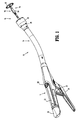
- Anvil shaft 64 includes a stepped surface or ring 74 which is configured to engage retention surfaces 50 ( FIG. 1B ) of flexible arms 48 to releasably secure anvil shaft 64 to anvil retainer 36.
- An orientation groove or grooves is provided in anvil shaft 64 beneath splines 76 to effect proper alignment of splines 76 about shaft 64 to facilitate proper alignment of anvil assembly 18 and shell assembly 20 when anvil assembly 18 is retracted (approximated) towards shell assembly 20.
- Anvil shaft 64 can have over-molded splines 76, or alternatively, the anvil shaft can have machined splines.
- Anvil shaft 64 has a series of longitudinally spaced projections in the form of pins 78 as shown.
- the pins 78 provide for a purse-string attachment location.
- the projections are shown in the form of pins, other outwardly extending elongated structure for retaining purse string suture is also contemplated. As shown, five pins are provided, although a fewer or greater number of pins are also contemplated.
- the pins 78 extend radially outwardly from the anvil shaft 64 and are positioned at an angle to a longitudinal axis of the anvil shaft. That is, a longitudinal axis of the pins is angled with respect to a longitudinal axis of the anvil shaft 64. In a preferred embodiment, the angle of the pins with respect to the longitudinal axis is between about 30 degrees and about 60 degrees, although other angles are also contemplated as long as they are sufficient to capture the suture.
- the pins 78 preferably angle toward the proximal end of the anvil shaft 64 to help retain the suture therebetween, but can alternatively be angled in other directions. Also, although shown as straight, the projections can be curved and/or have multiple angles.
- the pins can be pressed, machined or attached by other techniques to the anvil shaft 64.
- the projections e.g. pins, can be formed integrally/monolithically with the anvil shaft or separate components attached to the shaft.
- the pins are configured to receive a purse-string suture therebetween, thereby creating a catch or capturing region to retain the suture between two adjacent pins 78.
- the series of pins 78 enables the user to decide the amount of tissue desired for purse stringing, e.g. placing the suture between the two proximal pins 78a, 78b would enable additional tissue to be taken and presented for stapling compared to distal pins.
- suture can also be retained by wrapping around the individual pin or pins 78 instead of placement between two adjacent pins.
- pins are shown as substantially identical, the size and configuration of the pins can vary along the length of the anvil shaft 64. Also, although shown substantially equidistantly axially spaced, the distance between adjacent pins can vary.
- the anvil shaft is of circular cross-section with the pins extending radially from the circumferential surface of the anvil shaft.
- the anvil shaft 164 has a series of cutouts 178 forming cinch spots to grasp the suture. As shown, each of the cutouts 178 is arcuate and cut in a direction toward a distal end 165 of the anvil shaft 164. This angled cut forms a plurality of projecting surfaces or projections extending toward a proximal end 167 of the anvil shaft 164. The cutouts 178 narrow in dimension as they extend toward an opposing wall of the shaft, such that inner region 180 is narrower than outer region 181.
- the inner regions 180 preferably narrow to a dimension smaller than an outer dimension of the purse string suture so the suture is cinched within the inner region 180 when placed through the cutout 178.
- the user can select the amount of tissue desired by selecting the appropriate cutout 178 in which to cinch the suture, e.g. the more proximal the cutout, the more tissue to be taken and presented for stapling (the proximalmost cutouts 178a providing the most tissue). Although five cutouts are shown, a fewer or greater number of cutouts are also contemplated.
- the cutouts are also shown as extending to a depth approximately up to the central longitudinal axis of the shaft; cutouts of different depths are also contemplated. Also, although the cutouts as shown are substantially identical, the configuration of the cutouts can vary along the anvil shaft 164. Also, although shown equidistantly axially spaced, the spacing between the cutouts 178 can be varied. The remaining components, e.g. anvil head, are identical to the embodiment of Figure 1 .
- anvil retainer 36 ( FIG. 1B ) defines an elongated bore 42 which is dimensioned to receive anvil shaft 64 such that stepped surface 74 of shaft 64 engages retention surface 50 to releasably secure anvil assembly 18 to anvil retainer 36.
- anvil shaft 64 is of a length to protrude from the anus when properly positioned during a surgical procedure to treat colon prolapse. By protruding from the anus, the interface between the anvil shaft 64 and anvil retainer 36 is exposed and visible for attachment.
- shaft 64 extends outwardly from a face 86 ( FIG.
- anvil head 66 a distance greater than about three inches, and for example extends outwardly from face 86 of anvil head 66 a distance of about 3.55 inches.
- the shaft extends outwardly a distance of greater than about five inches, and for example extends about 5.234 inches.
- Anvil head 66 is shown with a low distal profile, however, other shapes are contemplated such as the bulbous, smoothly contoured anvil 266 illustrated in Figure 3A . Bulbous portion 296 facilitates insertion of head 266 through a purse string suture.
- the anvil head 266 can be attached to the anvil shafts disclosed herein.
- Cutting ring 292 is shown attached to anvil head 266.
- the bulbous anvil head can be used with anvils pivotally attached to an anvil shaft via anvil post 270.
- the bulbous anvil head can be non-pivotably attached to the anvil shaft such as anvil head 366, 466, shown in Figures 7 and 8 , respectively.
- bulbous anvil head 366 has an anvil post 368 which receives proximal end 365 of anvil shaft or center rod 364 thereover.
- a pin 372 (or other fastening or attachment structure) extends though opening 367 and 369 of anvil shaft 364 and anvil post 368, respectively, to fixedly (non-pivotably) secure the anvil shaft 364 to anvil head assembly 366.
- Anvil 373 containing annular rows of anvil depressions is secured to anvil head 366.
- Cutting ring 375 is positioned in a recess of anvil 373.
- the anvil assembly 318 is identical to the anvil assembly of Figure 1 and has, e.g. angled projections 378 for reception of purse string sutures, splines 376, etc.
- a marking ring 380 adjacent the proximalmost suture receiving structure can also be provided as shown in the embodiment of Figure 6 , as well as in the other embodiments disclosed herein, to indicate to the user that a proximalmost pin or cutout is being utilized which present the largest amount of tissue for stapling.
- a bulbous anvil head can also be used in a non-pivoting anvil assembly such as illustrated in Figure 8 .
- the anvil assembly 418 of Figure 8 is identical to the anvil assembly 165 of Figure 4 , except that the anvil head is non-pivotally attached to anvil shaft 464, a bulbous head 466 is provided, and a marking ring 480 is provided on anvil shaft 464 adjacent the proximalmost cutout 478a of the series of cutouts 478 forming projections.
- anvil heads of Figures 1 and 4 can be used with anvil assemblies wherein the anvil heads non-pivotably mounted to the anvil shafts, such as those of Figures 7 and 8 .
- shell assembly 20 is secured to the distal end of central body portion 14 .
- Shell assembly 20 includes a shell or housing 98, a pusher back 100, a cylindrical knife 102, and a staple guide housing one or more rows of staples (not shown). Vent holes 29 ( FIG. 1 ) are provided in shell assembly 20.
- Shell 98 includes an outer housing portion 106 and an inner guide portion 108 having grooves 110 for mating with splines 76 on anvil shaft 64.
- Outer housing portion 106 defines a throughbore 112 having a distal cylindrical section 114, a central conical section 116 and a proximal smaller diameter cylindrical section 118.
- a plurality of openings 120 are formed in conical section 116. Openings 116 are dimensioned to permit fluid and tissue passage during operation of stapler 10.
- a pair of diametrically opposed flexible engagement members 122 are formed on proximal cylindrical section 118 of shell 98. Engagement members 122 are positioned to be received in openings formed on a distal end of body portion 14 to secure shell 98 to body portion 14.
- Pusher back 100 includes a central throughbore 124 which is slidably positioned about inner guide portion 108 of shell 98.
- Pusher back 100 includes a distal cylindrical section 126 which is slidably positioned within distal cylindrical section 114 of shell 98, a central conical section 128 and a proximal smaller diameter cylindrical section 130.
- the proximal end of pusher back 100 includes members 132 which are configured to lockingly engage with a pusher link of stapler 10.
- Pusher back 100 also defines a receptacle 133 for receiving excised tissue.
- Receptacle 133 is preferably configured to have a depth of substantially within the range of approximately .275 cm (approximately.75 inches) to approximately .79 cm (approximately 2.0 inches).
- the receptacle 215 is configured to define a depth of approximately .52 cm (approximately 1.33 inches)
- the distal end of pusher back 100 includes a pusher 134.
- Pusher 134 includes a multiplicity of distally extending fingers 136 dimensioned to be slidably received within slots (not shown) formed in staple guide 104 to eject staples (not shown) therefrom.
- Cylindrical knife 102 is retained within the central throughbore of pusher back 100 to fixedly secure knife 102 in relation to pusher 134. Knife 102 may be retained within pusher back 100 using adhesives, crimping, pins, friction, etc.
- the distal end of knife 102 includes a circular cutting edge.
- the rigid bushing 140 is supported in the proximal end of inner guide portion 108 of shell 98.
- Bushing 140 defines a throughbore dimensioned to slidably receive anvil retainer 36 and anvil shaft 64 of anvil assembly 18.
- Bushing 140 provides lateral support for flexible arms 48 of anvil retainer 36 when the anvil assembly 18 has been approximated to prevent disengagement of anvil assembly 18 from anvil retainer 36. In the unapproximated position, flexible arms 48 are positioned externally of bushing 140 to permit flexing of the arms for removal of anvil assembly 18 from retainer 36.
- stapler 10 is particularly suitable for use in surgical procedures for treating colon prolapse.
- an access port can be inserted into the anus to facilitate access to the prolapsed colon.
- a purse string suture S1 is placed into, above or in the vicinity of the colon prolapse and the anvil assembly 318 is inserted through the access port into the anus and rectum.
- the purse string suture S1 is placed between (or alternately wrapped around) selected adjacent pins 378 (or pins 78) as shown in Figure 9 .
- Pins 378 are longitudinally spaced along shaft 364 such that the amount of tissue drawn into the shell assembly can be controlled by properly selecting the two pins 378 (or 78) to which the purse string suture is inserted between.
- a greater amount of tissue will be drawn into shell assembly by capturing and retaining the purse string suture between the two proximalmost pins 378a, 378b.
- the suture ends are tightened and pulled toward the user, therefore pulling the tissue proximally.
- the surgeon can then visualize the tissue to be stapled, i.e. the tissue donut to be removed.
- the stapling instrument e.g. instrument 10 of Figure 1 , is inserted through the port and attached to the anvil assembly, with the elongated anvil shaft and elongated instrument shaft providing increased visibility.
- Anvil assembly 318 and the shell assembly 20 are then approximated via knob 26 to draw the prolapsed colon into shell assembly 20.
- firing trigger 24 can be actuated or fired in a manner described in the '106 patent to staple, sever and allow removal of a portion of the prolapsed colon. Thereafter, the stapler is at least partially unapproximated and removed from the anus with the excised tissue contained within receptacle 133 of pusher back 100 within shell assembly 20. In the embodiments where a tilting anvil is used, after the firing step and sufficient movement of the anvil away from the shell assembly 20, the anvil will tilt (not shown) to its inoperative position to facilitate removal.
- Figure 10 illustrates a purse string suture S1 placed within a cutout 478 of anvil shaft 474 of anvil assembly 418 of Figure 8 .
- Figure 10 also illustrates the shell assembly 20 containing the staples with the procedural steps similar to that described above with reference to Figure 9 .
Abstract
Description
- The present disclosure relates to a surgical stapling device and more particularly to a surgical stapling device suitable for treatment of internal hemorrhoids.
- Anastomosis is the surgical joining of separate hollow organ sections. In known circular anastomosis procedures, two ends of organ sections are joined by means of a stapling device which drives a circular array of staples through each organ section and simultaneously cores any tissue interior of the driven circular array of staples to free a tubular passage. Examples of such devices are described n
U.S. Patent Nos. 7,234,624 ,6,945,444 ,6,053,390 ,5,588,579 ,5,119,983 ,4,646,745 ,4,576,167 ,4,473,077 . - Typically the circular stapling device has an elongated shaft having a handle portion at a proximal end and a staple cartridge at a distal end. An anvil assembly including an anvil rod with an attached anvil head is mounted to the distal end of the device. The anvil is approximated to clamp tissue between the staple holding component and the anvil. The clamped tissue is stapled by actuation of the handle portion to drive circular arrays of staples through the tissue and into anvil depressions on the anvil head to form the staples. An annular knife is advanced with the handle actuation to core tissue inboard of the staple array.
- Surgical stapling devices for performing circular anastomosis have also been used to treat hemorrhoids in the rectum. Hemorrhoids are masses of tissue in the anus containing enlarged blood vessels. Internal hemorrhoids are inside the anal canal; external hemorrhoids lie outside the anal canal. Hemorrhoidectomy is a surgical procedure in which the hemorrhoids are removed. Stapled hemorrhoidopexy is a surgical procedure in which a stapling device is used to remove tissue just above the hemorrhoids in order to pull the hemorrhoids back up inside the rectum and reduce the symptoms. The staples interrupt the blood flow of the superior hemorrhoidal arterial branches, cutting off the blood supply, thus causing the hemorrhoids to shrink. This is used for treatment of internal hemorrhoids.
- During the use of a circular stapling device for hemorrhoid treatment, the anvil head and the staple holding component of the device are inserted through and into the rectum with the anvil head and the stapling holding component in an open or unapproximated position. Thereafter, a purse string suture is used to pull the internal hemorrhoidal tissue and/or mucosal tissue toward the anvil rod. Next, the anvil head and the staple holding component are approximated to clamp the hemorrhoidal tissue and/or mucosal tissue between the anvil head and the staple holding component. The stapling device is fired to remove the hemorrhoidal tissue and/or mucosal tissue and staple the cut tissue.
- It would be advantageous to provide a device with an option to adjust the amount of tissue for purse stringing to enhance control over the amount of tissue removed.
-
WO 2008/107 918 discloses a circular anvil assembly according to the preamble of the appended independent claim. - The present disclosure provides a circular anvil assembly comprising an anvil shaft and an anvil head. The anvil head has anvil depression for forming surgical staples and is mounted to the anvil shaft. The anvil shaft has a longitudinal axis and first and second longitudinally spaced apart elongated projections attached to the anvil shaft and extending outwardly therefrom, the projections configured and dimensioned to retain a purse string suture.
- In a preferred embodiment, the projections are positioned at an acute angle with respect to the longitudinal axis of the anvil shaft, preferably angling away from the anvil head toward a proximal end of the anvil shaft. In one embodiment, the plurality of projections are substantially equidistantly axially spaced. In one embodiment, the projections comprise a plurality of elongated pins.
- The present disclosure also provides in another aspect a circular surgical stapler comprising a handle assembly, an elongated body portion extending distally from the handle assembly, and a head portion disposed adjacent a distal end of the elongated body portion and including the anvil assembly as above and a shell assembly. The anvil assembly is movable in relation to the shell assembly between spaced and approximated positions and has an anvil head and a plurality of elongated projections for receiving a purse string suture. The projections extend at an angle with respect to a longitudinal axis of the anvil shaft such that longitudinal axis of the projections are angled with respect to the longitudinal axis of the anvil shaft.
- In one embodiment, the anvil assembly includes an anvil shaft extending proximally of the anvil head and removably mountable to an anvil retainer of the stapler.
- Various embodiments of the present disclosure are described hereinbelow with reference to the drawings, wherein:
-
Figure 1 is a perspective view of a first embodiment of the surgical stapler of the present disclosure; -
Figure 1A is a longitudinal cross-sectional view of the surgical stapler ofFigure 1 ; -
Figure 1B is a cross-sectional view of the anvil retainer of the stapler ofFigure 1 ; -
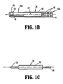
Figure 1C is a side view of the connector of the stapler ofFigure 1 ; -
Figures 1D and 1E are cross-sectional views of portions of the shell assembly ofFigure 1 ; -
Figures 2 and3 are close up perspective and side views, respectively, of the anvil assembly and shell assembly ofFigure 1 ; -
Figure 3A is a cross-sectional view of an alternate embodiment of the anvil head; -
Figure 4 is a side view of an alternative anvil assembly for use with the surgical stapler ofFigure 1 ; -
Figure 5 is a top view of a portion of the anvil shaft ofFigure 4 ; -
Figure 6 is an exploded view of an alternate embodiment of the anvil assembly of the present disclosure; -
Figure 7 is a perspective view of the anvil assembly ofFigure 6 ; -
Figure 8 is a perspective view of an alternative anvil assembly of the present disclosure; -
Figure 9 is a side view illustrating placement of the purse string suture in an anvil assembly of the present invention; and -
Figure 10 is a side view illustrating placement of the purse string suture in an alternative anvil assembly. - The presently disclosed surgical stapler will now be described in detail with reference to the drawings in which like reference numerals designate identical or corresponding elements in each of the several views. Throughout this description, the term "proximal" will refer to the portion of the stapler closer to the operator and the term "distal" will refer to the portion of the instrument further from the operator. The presently disclosed stapler is particularly suited for surgical procedures for the treatment of colon prolapse and hemorrhoids, although it can be used for other procedures.
-
FIGS. 1 and1A illustrate one embodiment of the presently disclosedhemorrhoid stapler 10. Briefly,surgical stapler 10 includes ahandle assembly 12, a central body orelongated portion 14 and adistal head portion 15.Head portion 15 includes ananvil assembly 18 and ashell assembly 20. Except where otherwise noted, the components ofstapler 10 are generally formed from thermoplastics including polycarbonates, and metals including stainless steel and aluminum. The particular material selected to form a particular component will depend upon the strength requirements of the particular component. For example, the anvil may be formed from a metal such as stainless steel, whereas portions ofhandle assembly 12 may be formed from thermoplastic such as a polycarbonate. Alternately, other materials having the requisite strength requirements which are suitable for surgical use may be used to form the components ofstapler 10. - Handle
assembly 12 includes astationary handle 22, a firingtrigger 24, anapproximation knob 26, anindicator assembly 28, and alockout mechanism 30.Approximation knob 26 functions to retract and advance adrive screw 32 to advance or retractanvil assembly 18 in relation toshell assembly 20. Firingtrigger 24 functions to advance apusher link 34 to actuate a pusher to eject staples fromshell assembly 20. Each of the components ofhandle assembly 12 identified above are substantially as described inU.S. Patent No. 7,303,106 ("'106 patent") entitled "Surgical Stapling Device With Visual Indicator" which issued on December 4, 2007. - Referring to
FIGS. 1A-1C , ananvil retainer 36 is secured to a distal end ofdrive screw 32 by aconnector 38.Anvil retainer 36 includes abody 40 defining anelongated bore 42. Aproximal end 40a ofbody 40 includes alongitudinal slot 44 and a pair oftransverse throughbores 46. Adistal end 40b ofbody 40 includes three segmentedflexible arms 48. Each of thearms 48 has aninner retention surface 50 which will be described in further detail below. -
Connector 38 includes acentral body 52 having aproximal extension 54 and adistal extension 56.Proximal extension 54 is dimensioned to be received within a slot (not shown) formed in the distal end ofdrive screw 32.Extension 54 and the distal end ofdrive screw 32 each define a transverse throughbore for receiving a pin, rivet, screw or the like 39A for fixedly securingconnector 38 to drivescrew 32.Distal extension 56 is dimensioned to be received withinslot 44 ofbody 40 ofanvil retainer 36.Extension 56 includes a pair of spaced throughbores which align withthroughbores 46 ofanvil retainer 36 and are dimensioned to receive pins, screws, rivets or the like 39B to fixedly secureanvil retainer 36 toconnector 38. Although pins, screws, rivets or the like are specifically disclosed for securingconnector 38 to drivescrew 32 andanvil retainer 36, other known fastening techniques are envisioned, e.g., welding, crimping, and interlocking structure. In an alternate embodiment, the connector and anvil retainer can be replaced with a single part, e.g. an elongated anvil retainer, having an extended length to function similarly to the extended length resulting from the provision ofconnector 38. - Referring to
FIGS. 2 and3 ,anvil assembly 18 includes an anvil shaft orcenter rod 64 and ananvil head 66.Anvil shaft 64 includes a tapered proximalblunt end 64a (Figure 1A ) and an opposite distal end for mounting toanvil post 68 ofanvil head 66. A pin 72 (or alternatively a screw, rivet or the like) mounts theanvil post 68 toanvil shaft 64. It should be appreciated, thatanvil post 68 can be pivotally mounted toanvil shaft 64 so that the anvil can move between an operative non-tilted position to a tilted position. This is described in detail inU.S. Patent 7,303,106 . Alternatively, the anvil can be fixedly (non-pivotably) mounted to theanvil shaft 64. This is shown for example in the embodiment ofFigures 6 and7 described below. -
Anvil shaft 64 includes a stepped surface orring 74 which is configured to engage retention surfaces 50 (FIG. 1B ) offlexible arms 48 to releasablysecure anvil shaft 64 toanvil retainer 36. An orientation groove or grooves is provided inanvil shaft 64 beneathsplines 76 to effect proper alignment ofsplines 76 aboutshaft 64 to facilitate proper alignment ofanvil assembly 18 andshell assembly 20 whenanvil assembly 18 is retracted (approximated) towardsshell assembly 20. -
Anvil shaft 64 can haveover-molded splines 76, or alternatively, the anvil shaft can have machined splines. -
Anvil shaft 64 has a series of longitudinally spaced projections in the form ofpins 78 as shown. Thepins 78 provide for a purse-string attachment location. Although the projections are shown in the form of pins, other outwardly extending elongated structure for retaining purse string suture is also contemplated. As shown, five pins are provided, although a fewer or greater number of pins are also contemplated. - The
pins 78 extend radially outwardly from theanvil shaft 64 and are positioned at an angle to a longitudinal axis of the anvil shaft. That is, a longitudinal axis of the pins is angled with respect to a longitudinal axis of theanvil shaft 64. In a preferred embodiment, the angle of the pins with respect to the longitudinal axis is between about 30 degrees and about 60 degrees, although other angles are also contemplated as long as they are sufficient to capture the suture. Thepins 78 preferably angle toward the proximal end of theanvil shaft 64 to help retain the suture therebetween, but can alternatively be angled in other directions. Also, although shown as straight, the projections can be curved and/or have multiple angles. The pins can be pressed, machined or attached by other techniques to theanvil shaft 64. The projections, e.g. pins, can be formed integrally/monolithically with the anvil shaft or separate components attached to the shaft. - The pins are configured to receive a purse-string suture therebetween, thereby creating a catch or capturing region to retain the suture between two
adjacent pins 78. The series ofpins 78 enables the user to decide the amount of tissue desired for purse stringing, e.g. placing the suture between the twoproximal pins - It should be appreciated that the suture can also be retained by wrapping around the individual pin or pins 78 instead of placement between two adjacent pins.
- Although the pins are shown as substantially identical, the size and configuration of the pins can vary along the length of the
anvil shaft 64. Also, although shown substantially equidistantly axially spaced, the distance between adjacent pins can vary. - In the illustrated embodiment, the anvil shaft is of circular cross-section with the pins extending radially from the circumferential surface of the anvil shaft.
- In the alternate anvil of
Figures 4 and 5 , a different structure is disclosed for capturing and retaining the purse string suture. Except for the suture retaining structure, the anvil assembly and shell assembly are identical to that described with respect to the embodiment ofFigure 1 . Theanvil shaft 164 is mountable to the surgical staplers disclosed herein. For brevity, the description of these identical components will not be repeated. - Turning to the structure for receiving the purse string suture of
Figures 4 and 5 , theanvil shaft 164 has a series ofcutouts 178 forming cinch spots to grasp the suture. As shown, each of thecutouts 178 is arcuate and cut in a direction toward adistal end 165 of theanvil shaft 164. This angled cut forms a plurality of projecting surfaces or projections extending toward aproximal end 167 of theanvil shaft 164. Thecutouts 178 narrow in dimension as they extend toward an opposing wall of the shaft, such thatinner region 180 is narrower thanouter region 181. Theinner regions 180 preferably narrow to a dimension smaller than an outer dimension of the purse string suture so the suture is cinched within theinner region 180 when placed through thecutout 178. As with thepins 78 described above, the user can select the amount of tissue desired by selecting theappropriate cutout 178 in which to cinch the suture, e.g. the more proximal the cutout, the more tissue to be taken and presented for stapling (theproximalmost cutouts 178a providing the most tissue). Although five cutouts are shown, a fewer or greater number of cutouts are also contemplated. The cutouts are also shown as extending to a depth approximately up to the central longitudinal axis of the shaft; cutouts of different depths are also contemplated. Also, although the cutouts as shown are substantially identical, the configuration of the cutouts can vary along theanvil shaft 164. Also, although shown equidistantly axially spaced, the spacing between thecutouts 178 can be varied. The remaining components, e.g. anvil head, are identical to the embodiment ofFigure 1 . - As discussed above, anvil retainer 36 (
FIG. 1B ) defines anelongated bore 42 which is dimensioned to receiveanvil shaft 64 such that steppedsurface 74 ofshaft 64 engagesretention surface 50 to releasablysecure anvil assembly 18 toanvil retainer 36. In one embodiment,anvil shaft 64 is of a length to protrude from the anus when properly positioned during a surgical procedure to treat colon prolapse. By protruding from the anus, the interface between theanvil shaft 64 andanvil retainer 36 is exposed and visible for attachment. For example, in one embodiment,shaft 64 extends outwardly from a face 86 (FIG. 2 ) of anvil head 66 a distance greater than about three inches, and for example extends outwardly fromface 86 of anvil head 66 a distance of about 3.55 inches. In another embodiment, the shaft extends outwardly a distance of greater than about five inches, and for example extends about 5.234 inches. -
Anvil head 66 is shown with a low distal profile, however, other shapes are contemplated such as the bulbous, smoothly contouredanvil 266 illustrated inFigure 3A .Bulbous portion 296 facilitates insertion ofhead 266 through a purse string suture. Theanvil head 266 can be attached to the anvil shafts disclosed herein. Cuttingring 292 is shown attached toanvil head 266. - The bulbous anvil head can be used with anvils pivotally attached to an anvil shaft via
anvil post 270. Alternatively, the bulbous anvil head can be non-pivotably attached to the anvil shaft such asanvil head Figures 7 and 8 , respectively. In the embodiment ofFigures 6 and7 ,bulbous anvil head 366 has ananvil post 368 which receivesproximal end 365 of anvil shaft orcenter rod 364 thereover. A pin 372 (or other fastening or attachment structure) extends though opening 367 and 369 ofanvil shaft 364 andanvil post 368, respectively, to fixedly (non-pivotably) secure theanvil shaft 364 toanvil head assembly 366.Anvil 373 containing annular rows of anvil depressions is secured toanvil head 366. Cuttingring 375 is positioned in a recess ofanvil 373. In all other respects, theanvil assembly 318 is identical to the anvil assembly ofFigure 1 and has, e.g. angledprojections 378 for reception of purse string sutures, splines 376, etc. A markingring 380 adjacent the proximalmost suture receiving structure can also be provided as shown in the embodiment ofFigure 6 , as well as in the other embodiments disclosed herein, to indicate to the user that a proximalmost pin or cutout is being utilized which present the largest amount of tissue for stapling. - A bulbous anvil head can also be used in a non-pivoting anvil assembly such as illustrated in
Figure 8 . Theanvil assembly 418 ofFigure 8 is identical to theanvil assembly 165 ofFigure 4 , except that the anvil head is non-pivotally attached toanvil shaft 464, abulbous head 466 is provided, and amarking ring 480 is provided onanvil shaft 464 adjacent the proximalmost cutout 478a of the series ofcutouts 478 forming projections. - It should be appreciated that the anvil heads of
Figures 1 and4 , respectively, can be used with anvil assemblies wherein the anvil heads non-pivotably mounted to the anvil shafts, such as those ofFigures 7 and 8 . - Referring to
FIGS. 1A ,1D and 1E ,shell assembly 20 is secured to the distal end ofcentral body portion 14 .Shell assembly 20 includes a shell or housing 98, a pusher back 100, acylindrical knife 102, and a staple guide housing one or more rows of staples (not shown). Vent holes 29 (FIG. 1 ) are provided inshell assembly 20. - Shell 98 includes an
outer housing portion 106 and aninner guide portion 108 havinggrooves 110 for mating withsplines 76 onanvil shaft 64.Outer housing portion 106 defines athroughbore 112 having a distalcylindrical section 114, a centralconical section 116 and a proximal smaller diametercylindrical section 118. A plurality ofopenings 120 are formed inconical section 116.Openings 116 are dimensioned to permit fluid and tissue passage during operation ofstapler 10. A pair of diametrically opposedflexible engagement members 122 are formed on proximalcylindrical section 118 of shell 98.Engagement members 122 are positioned to be received in openings formed on a distal end ofbody portion 14 to secure shell 98 tobody portion 14. - Pusher back 100 includes a
central throughbore 124 which is slidably positioned aboutinner guide portion 108 of shell 98. Pusher back 100 includes a distalcylindrical section 126 which is slidably positioned within distalcylindrical section 114 of shell 98, a centralconical section 128 and a proximal smaller diametercylindrical section 130. The proximal end of pusher back 100 includesmembers 132 which are configured to lockingly engage with a pusher link ofstapler 10. Pusher back 100 also defines areceptacle 133 for receiving excised tissue.Receptacle 133 is preferably configured to have a depth of substantially within the range of approximately .275 cm (approximately.75 inches) to approximately .79 cm (approximately 2.0 inches). For example, in one embodiment, the receptacle 215 is configured to define a depth of approximately .52 cm (approximately 1.33 inches) - The distal end of pusher back 100 includes a
pusher 134.Pusher 134 includes a multiplicity of distally extendingfingers 136 dimensioned to be slidably received within slots (not shown) formed in staple guide 104 to eject staples (not shown) therefrom.Cylindrical knife 102 is retained within the central throughbore of pusher back 100 to fixedlysecure knife 102 in relation topusher 134.Knife 102 may be retained within pusher back 100 using adhesives, crimping, pins, friction, etc. The distal end ofknife 102 includes a circular cutting edge. - The rigid bushing 140 is supported in the proximal end of
inner guide portion 108 of shell 98. Bushing 140 defines a throughbore dimensioned to slidably receiveanvil retainer 36 andanvil shaft 64 ofanvil assembly 18. Bushing 140 provides lateral support forflexible arms 48 ofanvil retainer 36 when theanvil assembly 18 has been approximated to prevent disengagement ofanvil assembly 18 fromanvil retainer 36. In the unapproximated position,flexible arms 48 are positioned externally of bushing 140 to permit flexing of the arms for removal ofanvil assembly 18 fromretainer 36. - As discussed above,
stapler 10 is particularly suitable for use in surgical procedures for treating colon prolapse. During such procedure, an access port can be inserted into the anus to facilitate access to the prolapsed colon. Next, a purse string suture S1 is placed into, above or in the vicinity of the colon prolapse and theanvil assembly 318 is inserted through the access port into the anus and rectum. Thereafter, the purse string suture S1 is placed between (or alternately wrapped around) selected adjacent pins 378 (or pins 78) as shown inFigure 9 .Pins 378 are longitudinally spaced alongshaft 364 such that the amount of tissue drawn into the shell assembly can be controlled by properly selecting the two pins 378 (or 78) to which the purse string suture is inserted between. A greater amount of tissue will be drawn into shell assembly by capturing and retaining the purse string suture between the twoproximalmost pins e.g. instrument 10 ofFigure 1 , is inserted through the port and attached to the anvil assembly, with the elongated anvil shaft and elongated instrument shaft providing increased visibility.Anvil assembly 318 and theshell assembly 20 are then approximated viaknob 26 to draw the prolapsed colon intoshell assembly 20. - When
surgical stapler 10 is fully approximated, firingtrigger 24 can be actuated or fired in a manner described in the '106 patent to staple, sever and allow removal of a portion of the prolapsed colon. Thereafter, the stapler is at least partially unapproximated and removed from the anus with the excised tissue contained withinreceptacle 133 of pusher back 100 withinshell assembly 20. In the embodiments where a tilting anvil is used, after the firing step and sufficient movement of the anvil away from theshell assembly 20, the anvil will tilt (not shown) to its inoperative position to facilitate removal. -
Figure 10 illustrates a purse string suture S1 placed within acutout 478 of anvil shaft 474 ofanvil assembly 418 ofFigure 8 .Figure 10 also illustrates theshell assembly 20 containing the staples with the procedural steps similar to that described above with reference toFigure 9 . - It will be understood that various modifications may be made to the embodiments disclosed herein. Therefore, the above description should not be construed as limiting, but merely as exemplifications of preferred embodiments.
Claims (9)
- A circular anvil assembly 18;318 comprising an anvil shaft 64;364 and an anvil head 66;366 the anvil head having anvil depressions for forming surgical staples, the anvil head mounted to the anvil shaft, the anvil shaft having a longitudinal axis; characterized in that the anvil shaft has first and second longitudinally spaced apart elongated projections 78;378 attached to the anvil shaft and extending outwardly therefrom, the projections configured and dimensioned to retain a purse string suture.
- The circular anvil assembly 18;318of claim 1, wherein the projections 78;378are positioned at an acute angle with respect to the longitudinal axis of the anvil shaft 64;364.
- The circular anvil assembly 18;318 of claims 1 or 2, wherein the plurality of projections 78;378 angle away from the anvil head 66;366 toward a proximal end of the anvil shaft 64;364.
- The circular anvil assembly 18;318 of any preceding claim, further comprising mounting structure on the anvil shaft 64;364 for releasably mounting the anvil shaft to a stapling instrument 10;310.
- The circular anvil assembly 18;318 of any preceding claim, wherein the plurality of projections 78;378 are substantially equidistantly axially spaced.
- The circular anvil assembly 18;318of any preceding claim, wherein the projections 78;378 comprise a plurality of elongated pins.
- A circular surgical stapler 10 comprising;
a handle assembly 12;
an elongated body portion 14 extending distally from the handle assembly; and
a head portion 15 disposed adjacent a distal end of the elongated body portion and including the circular anvil assembly (18;318) according to claim 1 and a shell assembly (20), the anvil assembly being movable in relation to the shell assembly between spaced and approximated positions. - The circular surgical stapler 10 of claim 7, wherein the anvil shaft 64;364 extends proximally of the anvil head 66;366, the anvil shaft being removably mounted to an anvil retainer of the stapler.
- The circular surgical stapler (10) of claim 7 or claim 8, wherein the projections 78;378 are attached to the anvil shaft 64;364 and comprise a plurality of pins angling toward the proximal end of the anvil shaft.
Priority Applications (1)
| Application Number | Priority Date | Filing Date | Title |
|---|---|---|---|
| EP12155451.3A EP2455008B1 (en) | 2009-01-06 | 2010-01-05 | Surgical stapler |
Applications Claiming Priority (2)
| Application Number | Priority Date | Filing Date | Title |
|---|---|---|---|
| US14266009P | 2009-01-06 | 2009-01-06 | |
| US12/637,841 US8408441B2 (en) | 2009-01-06 | 2009-12-15 | Surgical stapler |
Related Child Applications (2)
| Application Number | Title | Priority Date | Filing Date |
|---|---|---|---|
| EP12155451.3A Division EP2455008B1 (en) | 2009-01-06 | 2010-01-05 | Surgical stapler |
| EP12155451.3 Division-Into | 2012-02-14 |
Publications (3)
| Publication Number | Publication Date |
|---|---|
| EP2204125A2 EP2204125A2 (en) | 2010-07-07 |
| EP2204125A3 EP2204125A3 (en) | 2010-10-06 |
| EP2204125B1 true EP2204125B1 (en) | 2012-04-04 |
Family
ID=42115899
Family Applications (2)
| Application Number | Title | Priority Date | Filing Date |
|---|---|---|---|
| EP10250004A Not-in-force EP2204125B1 (en) | 2009-01-06 | 2010-01-05 | Surgical stapler anvil assembly |
| EP12155451.3A Not-in-force EP2455008B1 (en) | 2009-01-06 | 2010-01-05 | Surgical stapler |
Family Applications After (1)
| Application Number | Title | Priority Date | Filing Date |
|---|---|---|---|
| EP12155451.3A Not-in-force EP2455008B1 (en) | 2009-01-06 | 2010-01-05 | Surgical stapler |
Country Status (5)
| Country | Link |
|---|---|
| US (3) | US8408441B2 (en) |
| EP (2) | EP2204125B1 (en) |
| AT (1) | ATE551954T1 (en) |
| CA (1) | CA2689395C (en) |
| ES (2) | ES2556430T3 (en) |
Families Citing this family (160)
| Publication number | Priority date | Publication date | Assignee | Title |
|---|---|---|---|---|
| WO2006078694A2 (en) * | 2005-01-21 | 2006-07-27 | Mayo Foundation For Medical Education And Research | Thorascopic heart valve repair method and apparatus |
| US8231042B2 (en) * | 2008-11-06 | 2012-07-31 | Tyco Healthcare Group Lp | Surgical stapler |
| US8408441B2 (en) * | 2009-01-06 | 2013-04-02 | Covidien Lp | Surgical stapler |
| US8281974B2 (en) | 2009-01-14 | 2012-10-09 | Tyco Healthcare, Group LP | Surgical stapler with suture locator |
| US8418909B2 (en) * | 2009-06-02 | 2013-04-16 | Covidien Lp | Surgical instrument and method for performing a resection |
| US8146790B2 (en) | 2009-07-11 | 2012-04-03 | Tyco Healthcare Group Lp | Surgical instrument with safety mechanism |
| US8430292B2 (en) | 2009-10-28 | 2013-04-30 | Covidien Lp | Surgical fastening apparatus |
| US8322590B2 (en) * | 2009-10-28 | 2012-12-04 | Covidien Lp | Surgical stapling instrument |
| CN102029013B (en) * | 2010-12-14 | 2012-11-07 | 苏州天臣国际医疗科技有限公司 | Anus expander seat for surgery |
| US8708212B2 (en) | 2011-10-18 | 2014-04-29 | Covidien Lp | Tilt top anvil with torsion spring |
| US9016547B2 (en) | 2011-10-26 | 2015-04-28 | Covidien Lp | EEA tilt top anvil with ratchet/locking mechanism |
| US9010605B2 (en) | 2012-01-12 | 2015-04-21 | Covidien Lp | Sliding sleeve for circular stapling instrument reloads |
| US9022274B2 (en) | 2012-02-15 | 2015-05-05 | Covidien Lp | Circular stapler with increased lumen diameter |
| US9351734B2 (en) | 2012-06-19 | 2016-05-31 | Covidien Lp | Spring loaded anvil retainer |
| US10213205B2 (en) * | 2012-07-06 | 2019-02-26 | Covidien Lp | T-slot tilt anvil for circular stapling instrument |
| US9675359B2 (en) | 2012-10-10 | 2017-06-13 | Covidien Lp | Surgical instrument with preload assembly |
| US9572572B2 (en) | 2012-11-09 | 2017-02-21 | Covidien Lp | Circular stapler mechanical lockout |
| US9351724B2 (en) | 2013-01-11 | 2016-05-31 | Covidien Lp | Circular stapling instrument |
| US9592056B2 (en) | 2013-03-14 | 2017-03-14 | Covidien Lp | Powered stapling apparatus |
| CN104042292A (en) | 2013-03-15 | 2014-09-17 | 柯惠Lp公司 | Surgical anastomosis device comprising assemblies capable of being repeatedly utilized |
| US9532780B2 (en) | 2013-06-12 | 2017-01-03 | Covidien Lp | EEA anvil snap ring activator |
| US9668740B2 (en) | 2013-06-14 | 2017-06-06 | Covidien Lp | Anvil assembly with sliding sleeve |
| CA2911179C (en) | 2013-06-17 | 2022-03-29 | Covidien Lp | Surgical instrument with lockout mechanism |
| US9750503B2 (en) | 2013-07-11 | 2017-09-05 | Covidien Lp | Methods and devices for performing a surgical anastomosis |
| US9693773B2 (en) | 2013-09-11 | 2017-07-04 | Covidien Lp | Anvil assembly with sliding sleeve |
| US10709452B2 (en) | 2013-09-23 | 2020-07-14 | Ethicon Llc | Methods and systems for performing circular stapling |
| US10980542B2 (en) | 2016-11-14 | 2021-04-20 | Ethicon Llc | Circular surgical stapler with recessed deck |
| US9554802B2 (en) | 2013-11-13 | 2017-01-31 | Covidien Lp | Anvil assembly with frangible retaining member |
| US9517070B2 (en) | 2013-11-13 | 2016-12-13 | Covidien Lp | Anvil assembly and delivery system |
| US9913643B2 (en) | 2014-05-09 | 2018-03-13 | Covidien Lp | Interlock assemblies for replaceable loading unit |
| JP6377775B2 (en) | 2014-06-12 | 2018-08-22 | コヴィディエン リミテッド パートナーシップ | Surgical stapling device |
| US9867619B2 (en) | 2014-06-24 | 2018-01-16 | Covidien Lp | System for delivering an anvil assembly to a surgical site |
| US9861367B2 (en) | 2014-06-24 | 2018-01-09 | Covidien Lp | Anvil assembly delivery systems |
| EP3164084B1 (en) | 2014-07-04 | 2020-02-19 | Covidien LP | Loading unit with shipping member for surgical stapling device |
| US9757133B2 (en) | 2014-07-09 | 2017-09-12 | Covidien Lp | Methods and devices for performing a surgical anastomosis |
| CN104188701A (en) * | 2014-08-04 | 2014-12-10 | 北京中法派尔特医疗设备有限公司 | Stapler with suture fixing device |
| US10085744B2 (en) | 2014-12-08 | 2018-10-02 | Covidien Lp | Loading unit attachment band for surgical stapling instrument |
| US9855045B2 (en) | 2014-12-09 | 2018-01-02 | Covidien Lp | Anvil assembly delivery system |
| WO2016090600A1 (en) | 2014-12-11 | 2016-06-16 | Covidien Lp | Stapler with auto-matic lockout mechanism |
| US10499916B2 (en) | 2014-12-11 | 2019-12-10 | Covidien Lp | Surgical stapling loading unit |
| JP6518766B2 (en) | 2014-12-17 | 2019-05-22 | コヴィディエン リミテッド パートナーシップ | Surgical stapling device with firing indicator |
| US10039549B2 (en) | 2015-01-07 | 2018-08-07 | Covidien Lp | Loading unit retention clip for surgical stapling instrument |
| US10117656B2 (en) | 2015-01-07 | 2018-11-06 | Covidien Lp | Loading unit locking collar |
| US10022126B2 (en) | 2015-01-07 | 2018-07-17 | Covidien Lp | Loading unit locking collar |
| WO2016127433A1 (en) | 2015-02-15 | 2016-08-18 | Covidien Lp | Surgical stapling device with firing indicator of unitary construction |
| US10881408B2 (en) | 2015-04-22 | 2021-01-05 | Covidien Lp | Interlock assembly for replaceable loading units |
| US10426480B2 (en) | 2015-04-29 | 2019-10-01 | Covidien Lp | Cutting ring assembly with rigid cutting member |
| US9987001B2 (en) | 2015-06-12 | 2018-06-05 | Covidien Lp | Surgical anastomosis apparatus |
| US9974536B2 (en) | 2015-07-02 | 2018-05-22 | Covidien Lp | Anvil assemblies and delivery systems |
| US10111668B2 (en) | 2015-07-02 | 2018-10-30 | Covidien Lp | Anvil assembly with snap backup ring |
| US10117655B2 (en) | 2015-07-22 | 2018-11-06 | Covidien Lp | Loading unit locking band for surgical stapling instrument |
| US10085756B2 (en) | 2015-07-24 | 2018-10-02 | Covidien Lp | Anvil assembly and anvil assembly delivery system |
| US10117675B2 (en) | 2015-07-28 | 2018-11-06 | Covidien Lp | Trocar tip protector |
| US9980730B2 (en) | 2015-09-21 | 2018-05-29 | Covidien Lp | Loading unit locking collar with rotational actuated release |
| US10111684B2 (en) | 2015-09-25 | 2018-10-30 | Covidien Lp | Adapter assembly including a removable trocar assembly |
| US10542992B2 (en) | 2015-10-19 | 2020-01-28 | Covidien Lp | Loading unit with stretchable bushing |
| EP3364885B1 (en) | 2015-10-20 | 2020-12-02 | Covidien LP | Circular stapler with tissue gap indicator assembly |
| WO2017066939A1 (en) | 2015-10-21 | 2017-04-27 | Covidien Lp | Annular knife for surgical stapler |
| US10512466B2 (en) | 2015-11-05 | 2019-12-24 | Covidien Lp | Adapter assembly for surgical device |
| CN108289683B (en) | 2015-11-13 | 2021-06-25 | 柯惠有限合伙公司 | Circular stapler with audible indicator mechanism |
| WO2017096502A1 (en) | 2015-12-07 | 2017-06-15 | Covidien Lp | Anvil assembly and delivery system |
| US10390835B2 (en) | 2015-12-10 | 2019-08-27 | Covidien Lp | Surgical fastener apparatus with linear position sensor |
| US10524797B2 (en) | 2016-01-13 | 2020-01-07 | Covidien Lp | Adapter assembly including a removable trocar assembly |
| US10874399B2 (en) | 2016-02-04 | 2020-12-29 | Covidien Lp | Circular stapler with visual indicator mechanism |
| US10603042B2 (en) | 2016-02-10 | 2020-03-31 | Covidien Lp | Flexible circular stapler |
| US10398439B2 (en) | 2016-02-10 | 2019-09-03 | Covidien Lp | Adapter, extension, and connector assemblies for surgical devices |
| US10595871B2 (en) | 2016-05-10 | 2020-03-24 | Covidien Lp | Insertion instrument, adapter assemblies and protector assemblies for a flexible circular stapler |
| US11141162B2 (en) | 2016-07-08 | 2021-10-12 | Covidien Lp | Loading unit locking collar with linearly actuated release |
| US11452522B2 (en) | 2016-08-15 | 2022-09-27 | Covidien Lp | Circular stapling device with articulating anvil retainer assembly |
| US10426470B2 (en) | 2016-11-04 | 2019-10-01 | Covidien Lp | Stapling device with releasable knife carrier |
| US10499922B2 (en) | 2016-11-04 | 2019-12-10 | Covidien Lp | Stapling device with self-releasing knife carrier pusher |
| USD833608S1 (en) | 2016-11-14 | 2018-11-13 | Ethicon Llc | Stapling head feature for surgical stapler |
| USD830550S1 (en) * | 2016-11-14 | 2018-10-09 | Ethicon Llc | Surgical stapler |
| USD837373S1 (en) | 2016-11-14 | 2019-01-01 | Ethicon Llc | Surgical stapler |
| US10603041B2 (en) * | 2016-11-14 | 2020-03-31 | Ethicon Llc | Circular surgical stapler with angularly asymmetric deck features |
| US11241232B2 (en) | 2017-01-24 | 2022-02-08 | Covidien Lp | Surgical stapling device with resettable anvil assembly |
| CN110198674A (en) | 2017-01-25 | 2019-09-03 | 柯惠Lp公司 | Circular stapling device and application method |
| US10542993B2 (en) | 2017-02-24 | 2020-01-28 | Covidien Lp | Anvil assembly of circular stapling device including alignment splines |
| WO2018161301A1 (en) | 2017-03-09 | 2018-09-13 | Covidien Lp | End effector assembly for circular stapler apparatus |
| WO2018161314A1 (en) | 2017-03-09 | 2018-09-13 | Covidien Lp | Surgical stapling device with audible indicator mechanism |
| ES2924630T3 (en) | 2017-03-23 | 2022-10-10 | Covidien Lp | Circular stapling device with alignment serrations |
| US10342534B2 (en) | 2017-03-23 | 2019-07-09 | Covidien Lp | Surgical stapling device with releasable knife carrier |
| US10881409B2 (en) | 2017-05-02 | 2021-01-05 | Covidien Lp | Rotation assembly for a surgical device |
| US11596400B2 (en) | 2017-06-09 | 2023-03-07 | Covidien Lp | Handheld electromechanical surgical system |
| US10932784B2 (en) | 2017-06-09 | 2021-03-02 | Covidien Lp | Handheld electromechanical surgical system |
| US11045199B2 (en) | 2017-06-09 | 2021-06-29 | Covidien Lp | Handheld electromechanical surgical system |
| US10987107B2 (en) | 2017-07-05 | 2021-04-27 | Covidien Lp | Surgical stapling device |
| US11090054B2 (en) | 2017-08-07 | 2021-08-17 | Covidien Lp | Stapling device with resettable tilt anvil assembly |
| US10828026B2 (en) | 2017-08-08 | 2020-11-10 | Covidien Lp | Tiltable anvil assembly |
| US10695069B2 (en) | 2017-08-23 | 2020-06-30 | Covidien Lp | Circular stapling device with offset spline tip |
| US11234703B2 (en) | 2017-09-01 | 2022-02-01 | Covidien Lp | Circular stapling device with position ribs |
| US11324507B2 (en) | 2017-11-03 | 2022-05-10 | Covidien Lp | Device and method for attachment of a stomal sleeve |
| US11497501B2 (en) | 2018-03-26 | 2022-11-15 | Covidien Lp | Circular stapling device with A-frame splines |
| US10952734B2 (en) | 2018-04-23 | 2021-03-23 | Covidien Lp | Stapling device with cut ring biasing member |
| US11197676B2 (en) | 2018-06-28 | 2021-12-14 | Covidien Lp | Tie-down method for anvil assembly delivery system |
| US11241234B2 (en) | 2018-08-14 | 2022-02-08 | Covidien Lp | Anvil assembly with self-retaining backup member |
| CN112584780A (en) | 2018-08-24 | 2021-03-30 | 柯惠有限合伙公司 | Electric circular nailing device |
| US10973544B2 (en) | 2018-10-02 | 2021-04-13 | Covidien Lp | Retaining mechanism for trocar assembly |
| US11141163B2 (en) | 2018-10-04 | 2021-10-12 | Covidien Lp | Circular stapling device with anvil rotation locking structure |
| US11065005B2 (en) | 2018-11-07 | 2021-07-20 | Covidien Lp | Reload assembly for a circular stapling device |
| US11147561B2 (en) | 2018-11-28 | 2021-10-19 | Covidien Lp | Reload assembly for a circular stapling device |
| US11389263B2 (en) | 2018-12-13 | 2022-07-19 | Covidien Lp | Lockout mechanisms for surgical instruments |
| US11166728B2 (en) | 2019-02-08 | 2021-11-09 | Covidien Lp | Reload assembly for a circular stapling device |
| US11547411B2 (en) | 2019-02-22 | 2023-01-10 | Covidien Lp | Anastomosis wound protector |
| US11529144B2 (en) | 2019-02-22 | 2022-12-20 | Covidien Lp | Encapsulated plug assembly for electromechanical surgical devices |
| US11337701B2 (en) | 2019-03-01 | 2022-05-24 | Covidien Lp | Devices and methods for assembling adapter assemblies |
| US11331782B2 (en) | 2019-03-01 | 2022-05-17 | Covidien Lp | Reload assembly for a circular stapling device |
| US11457921B2 (en) | 2019-03-26 | 2022-10-04 | Covidien Lp | Anvil assembly for surgical stapling instrument |
| US11596410B2 (en) | 2019-04-05 | 2023-03-07 | Covidien Lp | Surgical stapling device |
| US11534164B2 (en) | 2019-04-05 | 2022-12-27 | Covidien Lp | Strain gauge stabilization in a surgical device |
| US11344330B2 (en) | 2019-04-16 | 2022-05-31 | Covidien Lp | Trocar assemblies for adapter assemblies for surgical stapling instruments |
| US11419631B2 (en) | 2019-04-16 | 2022-08-23 | Covidien Lp | Trocar assemblies for adapter assemblies for surgical stapling instruments |
| US11317945B2 (en) | 2019-04-16 | 2022-05-03 | Covidien Lp | Trocar assemblies for adapter assemblies for surgical stapling instruments |
| US11660116B2 (en) | 2019-04-16 | 2023-05-30 | Covidien Lp | Trocar assemblies for adapter assemblies for surgical stapling instruments |
| US11839378B2 (en) | 2019-04-19 | 2023-12-12 | Covidien Lp | Circular stapling instruments |
| US11399838B2 (en) | 2019-04-22 | 2022-08-02 | Covidien Lp | Reload assembly for circular stapling devices |
| US11246599B2 (en) | 2019-04-25 | 2022-02-15 | Covidien Lp | End effector for circular stapling instrument |
| US11896233B2 (en) | 2019-05-31 | 2024-02-13 | Covidien Lp | Circular stapling device |
| US11690624B2 (en) | 2019-06-21 | 2023-07-04 | Covidien Lp | Reload assembly injection molded strain gauge |
| US11446035B2 (en) | 2019-06-24 | 2022-09-20 | Covidien Lp | Retaining mechanisms for trocar assemblies |
| US11123101B2 (en) | 2019-07-05 | 2021-09-21 | Covidien Lp | Retaining mechanisms for trocar assemblies |
| US11357509B2 (en) | 2019-07-11 | 2022-06-14 | Covidien Lp | Reload assembly for a circular stapling device |
| US11192227B2 (en) | 2019-07-16 | 2021-12-07 | Covidien Lp | Reload assembly for circular stapling devices |
| US11464510B2 (en) | 2019-07-26 | 2022-10-11 | Covidien Lp | Reload assembly with knife carrier lockout |
| US11253255B2 (en) | 2019-07-26 | 2022-02-22 | Covidien Lp | Knife lockout wedge |
| US11399825B2 (en) | 2019-10-28 | 2022-08-02 | Covidien Lp | Reload assembly with knife carrier lockout |
| US11553918B2 (en) | 2019-12-16 | 2023-01-17 | Covidien Lp | Reload assembly with knife carrier lockout |
| US11730481B2 (en) | 2020-01-06 | 2023-08-22 | Covidien Lp | Assemblies for retaining a trocar assembly |
| US11517317B2 (en) | 2020-01-06 | 2022-12-06 | Covidien Lp | Trocar release assemblies for a surgical stapler |
| US11911038B2 (en) | 2020-01-13 | 2024-02-27 | Covidien Lp | Cut optimization for excessive tissue conditions |
| US11523828B2 (en) | 2020-01-28 | 2022-12-13 | Covidien Lp | Sealed reload assembly for stapling device |
| US11622767B2 (en) | 2020-02-19 | 2023-04-11 | Covidien Lp | Sealed trocar assembly for stapling device |
| US11547438B2 (en) | 2020-02-24 | 2023-01-10 | Covidien Lp | Tip protector for ensuring trocar insertion |
| US11382630B2 (en) | 2020-02-25 | 2022-07-12 | Covidien Lp | Surgical stapling device with two part knife assembly |
| US11779343B2 (en) | 2020-02-26 | 2023-10-10 | Covidien Lp | Staple reload assembly with releasable knife |
| US11298152B2 (en) | 2020-02-28 | 2022-04-12 | Covidien Lp | Trocar retaining mechanism including band support |
| US11272998B2 (en) | 2020-03-04 | 2022-03-15 | Covidien Lp | Strain gage fixation in tension |
| US11426169B2 (en) | 2020-03-24 | 2022-08-30 | Covidien Lp | Retaining mechanisms for trocar assemblies |
| US11350939B2 (en) | 2020-03-24 | 2022-06-07 | Covidien Lp | Retaining mechanisms for trocar assemblies |
| US11426170B2 (en) | 2020-03-24 | 2022-08-30 | Covidien Lp | Retaining mechanisms for trocar assemblies |
| US11653925B2 (en) | 2020-05-21 | 2023-05-23 | Covidien Lp | Tissue relaxation monitoring for optimized tissue stapling |
| US11547405B2 (en) | 2020-05-22 | 2023-01-10 | Covidien Lp | Surgical stapling device |
| US11553921B2 (en) | 2020-07-15 | 2023-01-17 | Covidien Lp | Surgical stapling device with flexible shaft |
| US11547412B2 (en) | 2020-07-22 | 2023-01-10 | Covidien Lp | Surgical instruments and methods of assembly |
| US11877744B2 (en) | 2020-08-14 | 2024-01-23 | Covidien Lp | Low-cost powered stapler with end stop selection |
| US11627966B2 (en) | 2020-08-26 | 2023-04-18 | Covidien Lp | Surgical stapling device |
| US11801054B2 (en) | 2020-09-22 | 2023-10-31 | Covidien Lp | Surgical stapler with oval tool assembly |
| US11712509B2 (en) | 2020-10-02 | 2023-08-01 | Covidien Lp | Seal assembly for circular stapling instrument |
| US11627967B2 (en) | 2020-11-23 | 2023-04-18 | Covidien Lp | Trans-anastomotic insertion device |
| US11877750B2 (en) | 2021-01-21 | 2024-01-23 | Covidien Lp | Surgical stapler with powered and manual functions |
| US11786241B2 (en) | 2021-02-16 | 2023-10-17 | Covidien Lp | Surgical stapling device including a hydraulic staple formation mechanism |
| US11553920B2 (en) | 2021-05-03 | 2023-01-17 | Covidien Lp | Trocar retainer assembly for surgical stapler |
| US11490894B1 (en) | 2021-05-12 | 2022-11-08 | Covidien Lp | Surgical device with grease filter |
| US11642131B2 (en) | 2021-05-17 | 2023-05-09 | Covidien Lp | Devices and methods for shortening a rectal stump during a lower anterior resection procedure |
| US11612400B2 (en) | 2021-05-24 | 2023-03-28 | Covidien Lp | Trocar assembly with bearing assembly for load sharing |
| US11819208B2 (en) | 2021-08-05 | 2023-11-21 | Covidien Lp | Handheld electromechanical surgical device with strain gauge drift detection |
| US11744592B2 (en) | 2021-08-05 | 2023-09-05 | Covidien Lp | Handheld electromechanical stapler with tissue thickness detection |
| US11737759B2 (en) | 2021-08-05 | 2023-08-29 | Covidien Lp | Surgical stapling device accommodating prolapsed tissue |
| US11883028B2 (en) | 2021-09-08 | 2024-01-30 | Covidien Lp | Systems and methods for post-operative anastomotic leak detection |
| US11717299B2 (en) | 2021-10-12 | 2023-08-08 | Covidien Lp | Surgical stapling device with probiotics |
Family Cites Families (81)
| Publication number | Priority date | Publication date | Assignee | Title |
|---|---|---|---|---|
| US4576167A (en) | 1981-09-03 | 1986-03-18 | United States Surgical Corporation | Surgical stapler apparatus with curved shaft |
| US4473077A (en) | 1982-05-28 | 1984-09-25 | United States Surgical Corporation | Surgical stapler apparatus with flexible shaft |
| US4592354A (en) * | 1983-10-11 | 1986-06-03 | Senmed, Inc. | Tissue retention spool for intraluminal anastomotic surgical stapling instrument and methods |
| US4703887A (en) * | 1985-01-28 | 1987-11-03 | Ethicon, Inc. | Collapsible purse string aid for use with intraluminal stapling device |
| US4665917A (en) * | 1985-01-28 | 1987-05-19 | Ethicon, Inc. | Tissue gripper for use with intraluminal stapling device |
| AU7286587A (en) | 1986-04-21 | 1987-11-24 | Globe Control Finanzaktiengesellschaft | Anastomosis process and device |
| US5119983A (en) | 1987-05-26 | 1992-06-09 | United States Surgical Corporation | Surgical stapler apparatus |
| SU1509052A1 (en) | 1988-01-18 | 1989-09-23 | С. А. Попов | Surgical suturing apparatus |
| US5350104A (en) * | 1991-08-23 | 1994-09-27 | Ethicon, Inc. | Sealing means for endoscopic surgical anastomosis stapling instrument |
| US5355897A (en) * | 1992-04-16 | 1994-10-18 | Ethicon, Inc. | Method of performing a pyloroplasty/pylorectomy using a stapler having a shield |
| US5344059A (en) | 1992-05-19 | 1994-09-06 | United States Surgical Corporation | Surgical apparatus and anvil delivery system therefor |
| US5261920A (en) * | 1992-08-21 | 1993-11-16 | Ethicon, Inc. | Anvil bushing for circular stapler |
| US5309927A (en) * | 1992-10-22 | 1994-05-10 | Ethicon, Inc. | Circular stapler tissue retention spring method |
| CA2146508C (en) | 1994-08-25 | 2006-11-14 | Robert H. Schnut | Anvil for circular stapler |
| US5839639A (en) * | 1995-08-17 | 1998-11-24 | Lasersurge, Inc. | Collapsible anvil assembly and applicator instrument |
| US6083241A (en) * | 1998-11-23 | 2000-07-04 | Ethicon Endo-Surgery, Inc. | Method of use of a circular stapler for hemorrhoidal procedure |
| US6102271A (en) * | 1998-11-23 | 2000-08-15 | Ethicon Endo-Surgery, Inc. | Circular stapler for hemorrhoidal surgery |
| US6193129B1 (en) * | 2000-01-24 | 2001-02-27 | Ethicon Endo-Surgery, Inc. | Cutting blade for a surgical anastomosis stapling instrument |
| US6945444B2 (en) | 2001-04-03 | 2005-09-20 | Tyco Healthcare Group, Lp | Surgical stapling device for performing circular anastomoses |
| US7128748B2 (en) * | 2002-03-26 | 2006-10-31 | Synovis Life Technologies, Inc. | Circular stapler buttress combination |
| EP2228018B1 (en) * | 2002-06-17 | 2012-05-09 | Tyco Healthcare Group LP | Annular support structures |
| EP1545338B1 (en) | 2002-10-04 | 2009-04-15 | Tyco Healthcare Group Lp | Surgical stapling device |
| US20040217146A1 (en) * | 2002-12-20 | 2004-11-04 | Joachim Beck | Surgical stapler apparatus and method |
| CA2508935C (en) * | 2002-12-20 | 2011-03-15 | Tyco Healthcare Group, Lp | Vacuum assisted surgical stapler |
| ES2550808T3 (en) * | 2003-06-20 | 2015-11-12 | Covidien Lp | Surgical stapling instrument |
| EP2620104A3 (en) * | 2003-07-16 | 2014-05-14 | Covidien LP | Surgical stapling device with tissue tensioner |
| US20050059997A1 (en) * | 2003-09-17 | 2005-03-17 | Bauman Ann M. | Circular stapler buttress |
| US7547312B2 (en) * | 2003-09-17 | 2009-06-16 | Gore Enterprise Holdings, Inc. | Circular stapler buttress |
| US8181840B2 (en) * | 2004-03-19 | 2012-05-22 | Tyco Healthcare Group Lp | Tissue tensioner assembly and approximation mechanism for surgical stapling device |
| US7318830B2 (en) * | 2004-04-12 | 2008-01-15 | Mayoral Jaime L | Apparatus and method of use of a circular surgical stapler |
| JP4257270B2 (en) * | 2004-07-14 | 2009-04-22 | オリンパス株式会社 | Biological tissue suturing method and biological tissue suturing device |
| US7410086B2 (en) * | 2004-07-28 | 2008-08-12 | Ethicon Endo-Surgery, Inc. | Electroactive polymer-based actuation mechanism for circular stapler |
| US8372094B2 (en) * | 2004-10-15 | 2013-02-12 | Covidien Lp | Seal element for anastomosis |
| WO2006044194A2 (en) * | 2004-10-18 | 2006-04-27 | Tyco Healthcare Group, Lp | Compression anastomosis device and method |
| US7455682B2 (en) * | 2004-10-18 | 2008-11-25 | Tyco Healthcare Group Lp | Structure containing wound treatment material |
| US7938307B2 (en) * | 2004-10-18 | 2011-05-10 | Tyco Healthcare Group Lp | Support structures and methods of using the same |
| CA2584019C (en) * | 2004-10-18 | 2014-09-16 | Tyco Healthcare Group Lp | Structure for applying sprayable wound treatment material |
| AU2005295811B2 (en) * | 2004-10-18 | 2011-03-03 | Covidien Lp | Adhesive suture structure and methods of using the same |
| US7717313B2 (en) * | 2004-10-18 | 2010-05-18 | Tyco Healthcare Group Lp | Surgical apparatus and structure for applying sprayable wound treatment material |
| US7845536B2 (en) * | 2004-10-18 | 2010-12-07 | Tyco Healthcare Group Lp | Annular adhesive structure |
| WO2006044490A2 (en) * | 2004-10-18 | 2006-04-27 | Tyco Healthcare Group, Lp | Annular adhesive structure |
| US7942890B2 (en) * | 2005-03-15 | 2011-05-17 | Tyco Healthcare Group Lp | Anastomosis composite gasket |
| US20070203510A1 (en) * | 2006-02-28 | 2007-08-30 | Bettuchi Michael J | Annular disk for reduction of anastomotic tension and methods of using the same |
| US20100016888A1 (en) * | 2005-05-05 | 2010-01-21 | Allison Calabrese | Surgical Gasket |
| DE602006010845D1 (en) * | 2006-07-07 | 2010-01-14 | Ethicon Endo Surgery Inc | Surgical stapling device |
| US8205782B2 (en) * | 2006-07-12 | 2012-06-26 | Niti Surgical Solutions Ltd. | Compression assemblies and applicators for use therewith |
| US7708180B2 (en) * | 2006-11-09 | 2010-05-04 | Ethicon Endo-Surgery, Inc. | Surgical fastening device with initiator impregnation of a matrix or buttress to improve adhesive application |
| US8177798B2 (en) * | 2006-12-05 | 2012-05-15 | Tyco Healthcare Group Lp | Adhesive coated stent and insertion instrument |
| AU2007348492B9 (en) * | 2007-03-07 | 2013-04-18 | Covidien Ag | Stapler for mucosectomy |
| US8038045B2 (en) * | 2007-05-25 | 2011-10-18 | Tyco Healthcare Group Lp | Staple buttress retention system |
| US7832408B2 (en) * | 2007-06-04 | 2010-11-16 | Ethicon Endo-Surgery, Inc. | Surgical instrument having a directional switching mechanism |
| US7967181B2 (en) * | 2007-08-29 | 2011-06-28 | Tyco Healthcare Group Lp | Rotary knife cutting systems |
| US8181838B2 (en) * | 2008-09-10 | 2012-05-22 | Tyco Healthcare Group Lp | Surgical stapling device |
| US7837080B2 (en) * | 2008-09-18 | 2010-11-23 | Ethicon Endo-Surgery, Inc. | Surgical stapling instrument with device for indicating when the instrument has cut through tissue |
| US7918377B2 (en) * | 2008-10-16 | 2011-04-05 | Ethicon Endo-Surgery, Inc. | Surgical stapling instrument with apparatus for providing anvil position feedback |
| US8231042B2 (en) * | 2008-11-06 | 2012-07-31 | Tyco Healthcare Group Lp | Surgical stapler |
| US8408441B2 (en) * | 2009-01-06 | 2013-04-02 | Covidien Lp | Surgical stapler |
| US8281974B2 (en) * | 2009-01-14 | 2012-10-09 | Tyco Healthcare, Group LP | Surgical stapler with suture locator |
| US8418909B2 (en) * | 2009-06-02 | 2013-04-16 | Covidien Lp | Surgical instrument and method for performing a resection |
| US8276802B2 (en) * | 2009-07-11 | 2012-10-02 | Tyco Healthcare Group Lp | Surgical instrument with double cartridge and anvil assemblies |
| US8474679B2 (en) * | 2009-07-13 | 2013-07-02 | C.R. Bard, Inc. | Instrument for applying a surgical fastener |
| US8267301B2 (en) * | 2009-08-19 | 2012-09-18 | Tyco Healthcare Group Lp | Surgical stapler |
| US8646674B2 (en) * | 2010-05-11 | 2014-02-11 | Ethicon Endo-Surgery, Inc. | Methods and apparatus for delivering tissue treatment compositions to stapled tissue |
| US8464925B2 (en) * | 2010-05-11 | 2013-06-18 | Ethicon Endo-Surgery, Inc. | Methods and apparatus for delivering tissue treatment compositions to stapled tissue |
| US8453906B2 (en) * | 2010-07-14 | 2013-06-04 | Ethicon Endo-Surgery, Inc. | Surgical instruments with electrodes |
| EP2613714B1 (en) * | 2010-09-09 | 2021-08-11 | Queen Mary & Westfield College, University of London | Apparatus for forming stoma trephines and anastomoses |
| US8870911B2 (en) * | 2010-09-09 | 2014-10-28 | Queen Mary & Westfield College | Forceps comprising a trocar tip |
| US8479968B2 (en) * | 2011-03-10 | 2013-07-09 | Covidien Lp | Surgical instrument buttress attachment |
| JP5220153B2 (en) * | 2011-03-29 | 2013-06-26 | 富士フイルム株式会社 | Tube anastomosis |
| US9649113B2 (en) * | 2011-04-27 | 2017-05-16 | Covidien Lp | Device for monitoring physiological parameters in vivo |
| US8490850B2 (en) * | 2011-04-29 | 2013-07-23 | Covidien Lp | Circular stapler with controlled tissue compression |
| US20130026209A1 (en) * | 2011-07-27 | 2013-01-31 | Patrick Mozdzierz | Surgical Fastener Applying Apparatus |
| US20130060258A1 (en) * | 2011-08-26 | 2013-03-07 | Carman Giacomantonio | Endoluminal Surgical Instrument for Stapling, Cutting and Dividing |
| US9010608B2 (en) * | 2011-12-14 | 2015-04-21 | Covidien Lp | Releasable buttress retention on a surgical stapler |
| US9113885B2 (en) * | 2011-12-14 | 2015-08-25 | Covidien Lp | Buttress assembly for use with surgical stapling device |
| US8967448B2 (en) * | 2011-12-14 | 2015-03-03 | Covidien Lp | Surgical stapling apparatus including buttress attachment via tabs |
| US9186148B2 (en) * | 2012-01-05 | 2015-11-17 | Ethicon Endo-Surgery, Inc. | Tissue stapler anvil feature to prevent premature jaw opening |
| US9010605B2 (en) * | 2012-01-12 | 2015-04-21 | Covidien Lp | Sliding sleeve for circular stapling instrument reloads |
| US9010612B2 (en) * | 2012-01-26 | 2015-04-21 | Covidien Lp | Buttress support design for EEA anvil |
| US9351734B2 (en) * | 2012-06-19 | 2016-05-31 | Covidien Lp | Spring loaded anvil retainer |
| US9572572B2 (en) * | 2012-11-09 | 2017-02-21 | Covidien Lp | Circular stapler mechanical lockout |
-
2009
- 2009-12-15 US US12/637,841 patent/US8408441B2/en not_active Expired - Fee Related
- 2009-12-31 CA CA2689395A patent/CA2689395C/en not_active Expired - Fee Related
-
2010
- 2010-01-05 AT AT10250004T patent/ATE551954T1/en active
- 2010-01-05 EP EP10250004A patent/EP2204125B1/en not_active Not-in-force
- 2010-01-05 ES ES12155451.3T patent/ES2556430T3/en active Active
- 2010-01-05 ES ES10250004T patent/ES2381483T3/en active Active
- 2010-01-05 EP EP12155451.3A patent/EP2455008B1/en not_active Not-in-force
-
2013
- 2013-02-19 US US13/769,961 patent/US8746531B2/en not_active Expired - Fee Related
-
2014
- 2014-04-30 US US14/265,792 patent/US20140236228A1/en not_active Abandoned
Also Published As
| Publication number | Publication date |
|---|---|
| US8408441B2 (en) | 2013-04-02 |
| EP2455008B1 (en) | 2015-11-18 |
| EP2204125A2 (en) | 2010-07-07 |
| EP2455008A1 (en) | 2012-05-23 |
| CA2689395A1 (en) | 2010-07-06 |
| US20140236228A1 (en) | 2014-08-21 |
| US20100170932A1 (en) | 2010-07-08 |
| ES2381483T3 (en) | 2012-05-28 |
| ATE551954T1 (en) | 2012-04-15 |
| EP2204125A3 (en) | 2010-10-06 |
| US20130186930A1 (en) | 2013-07-25 |
| ES2556430T3 (en) | 2016-01-15 |
| CA2689395C (en) | 2017-05-16 |
| US8746531B2 (en) | 2014-06-10 |
Similar Documents
| Publication | Publication Date | Title |
|---|---|---|
| EP2204125B1 (en) | Surgical stapler anvil assembly | |
| US8281974B2 (en) | Surgical stapler with suture locator | |
| EP2286740B1 (en) | Surgical stapler | |
| US10575847B2 (en) | Circular surgical stapler with mating anvil and shell assembly | |
| US9113871B2 (en) | Surgical stapling device | |
| EP1377222B1 (en) | Surgical stapling device | |
| EP2614786A1 (en) | Device for performing a surgical anastomosis | |
| AU2006246455B2 (en) | Surgical stapling device |
Legal Events
| Date | Code | Title | Description |
|---|---|---|---|
| PUAI | Public reference made under article 153(3) epc to a published international application that has entered the european phase |
Free format text: ORIGINAL CODE: 0009012 |
|
| AK | Designated contracting states |
Kind code of ref document: A2 Designated state(s): AT BE BG CH CY CZ DE DK EE ES FI FR GB GR HR HU IE IS IT LI LT LU LV MC MK MT NL NO PL PT RO SE SI SK SM TR |
|
| AX | Request for extension of the european patent |
Extension state: AL BA RS |
|
| PUAL | Search report despatched |
Free format text: ORIGINAL CODE: 0009013 |
|
| AK | Designated contracting states |
Kind code of ref document: A3 Designated state(s): AT BE BG CH CY CZ DE DK EE ES FI FR GB GR HR HU IE IS IT LI LT LU LV MC MK MT NL NO PL PT RO SE SI SK SM TR |
|
| AX | Request for extension of the european patent |
Extension state: AL BA RS |
|
| 17P | Request for examination filed |
Effective date: 20110405 |
|
| RIC1 | Information provided on ipc code assigned before grant |
Ipc: A61B 17/115 20060101AFI20110615BHEP |
|
| GRAP | Despatch of communication of intention to grant a patent |
Free format text: ORIGINAL CODE: EPIDOSNIGR1 |
|
| RAP1 | Party data changed (applicant data changed or rights of an application transferred) |
Owner name: TYCO HEALTHCARE GROUP LP |
|
| GRAS | Grant fee paid |
Free format text: ORIGINAL CODE: EPIDOSNIGR3 |
|
| GRAA | (expected) grant |
Free format text: ORIGINAL CODE: 0009210 |
|
| AK | Designated contracting states |
Kind code of ref document: B1 Designated state(s): AT BE BG CH CY CZ DE DK EE ES FI FR GB GR HR HU IE IS IT LI LT LU LV MC MK MT NL NO PL PT RO SE SI SK SM TR |
|
| REG | Reference to a national code |
Ref country code: GB Ref legal event code: FG4D |
|
| REG | Reference to a national code |
Ref country code: CH Ref legal event code: EP |
|
| REG | Reference to a national code |
Ref country code: AT Ref legal event code: REF Ref document number: 551954 Country of ref document: AT Kind code of ref document: T Effective date: 20120415 |
|
| REG | Reference to a national code |
Ref country code: IE Ref legal event code: FG4D |
|
| REG | Reference to a national code |
Ref country code: ES Ref legal event code: FG2A Ref document number: 2381483 Country of ref document: ES Kind code of ref document: T3 Effective date: 20120528 |
|
| REG | Reference to a national code |
Ref country code: DE Ref legal event code: R096 Ref document number: 602010001247 Country of ref document: DE Effective date: 20120531 |
|
| REG | Reference to a national code |
Ref country code: NL Ref legal event code: VDEP Effective date: 20120404 |
|
| REG | Reference to a national code |
Ref country code: AT Ref legal event code: MK05 Ref document number: 551954 Country of ref document: AT Kind code of ref document: T Effective date: 20120404 |
|
| LTIE | Lt: invalidation of european patent or patent extension |
Effective date: 20120404 |
|
| PG25 | Lapsed in a contracting state [announced via postgrant information from national office to epo] |
Ref country code: LT Free format text: LAPSE BECAUSE OF FAILURE TO SUBMIT A TRANSLATION OF THE DESCRIPTION OR TO PAY THE FEE WITHIN THE PRESCRIBED TIME-LIMIT Effective date: 20120404 Ref country code: SI Free format text: LAPSE BECAUSE OF FAILURE TO SUBMIT A TRANSLATION OF THE DESCRIPTION OR TO PAY THE FEE WITHIN THE PRESCRIBED TIME-LIMIT Effective date: 20120404 Ref country code: CY Free format text: LAPSE BECAUSE OF FAILURE TO SUBMIT A TRANSLATION OF THE DESCRIPTION OR TO PAY THE FEE WITHIN THE PRESCRIBED TIME-LIMIT Effective date: 20120404 Ref country code: PL Free format text: LAPSE BECAUSE OF FAILURE TO SUBMIT A TRANSLATION OF THE DESCRIPTION OR TO PAY THE FEE WITHIN THE PRESCRIBED TIME-LIMIT Effective date: 20120404 Ref country code: NO Free format text: LAPSE BECAUSE OF FAILURE TO SUBMIT A TRANSLATION OF THE DESCRIPTION OR TO PAY THE FEE WITHIN THE PRESCRIBED TIME-LIMIT Effective date: 20120704 Ref country code: SE Free format text: LAPSE BECAUSE OF FAILURE TO SUBMIT A TRANSLATION OF THE DESCRIPTION OR TO PAY THE FEE WITHIN THE PRESCRIBED TIME-LIMIT Effective date: 20120404 Ref country code: IS Free format text: LAPSE BECAUSE OF FAILURE TO SUBMIT A TRANSLATION OF THE DESCRIPTION OR TO PAY THE FEE WITHIN THE PRESCRIBED TIME-LIMIT Effective date: 20120804 Ref country code: FI Free format text: LAPSE BECAUSE OF FAILURE TO SUBMIT A TRANSLATION OF THE DESCRIPTION OR TO PAY THE FEE WITHIN THE PRESCRIBED TIME-LIMIT Effective date: 20120404 |
|
| PG25 | Lapsed in a contracting state [announced via postgrant information from national office to epo] |
Ref country code: LV Free format text: LAPSE BECAUSE OF FAILURE TO SUBMIT A TRANSLATION OF THE DESCRIPTION OR TO PAY THE FEE WITHIN THE PRESCRIBED TIME-LIMIT Effective date: 20120404 Ref country code: PT Free format text: LAPSE BECAUSE OF FAILURE TO SUBMIT A TRANSLATION OF THE DESCRIPTION OR TO PAY THE FEE WITHIN THE PRESCRIBED TIME-LIMIT Effective date: 20120806 Ref country code: HR Free format text: LAPSE BECAUSE OF FAILURE TO SUBMIT A TRANSLATION OF THE DESCRIPTION OR TO PAY THE FEE WITHIN THE PRESCRIBED TIME-LIMIT Effective date: 20120404 Ref country code: GR Free format text: LAPSE BECAUSE OF FAILURE TO SUBMIT A TRANSLATION OF THE DESCRIPTION OR TO PAY THE FEE WITHIN THE PRESCRIBED TIME-LIMIT Effective date: 20120705 |
|
| RAP2 | Party data changed (patent owner data changed or rights of a patent transferred) |
Owner name: COVIDIEN LP |
|
| PG25 | Lapsed in a contracting state [announced via postgrant information from national office to epo] |
Ref country code: BE Free format text: LAPSE BECAUSE OF FAILURE TO SUBMIT A TRANSLATION OF THE DESCRIPTION OR TO PAY THE FEE WITHIN THE PRESCRIBED TIME-LIMIT Effective date: 20120404 |
|
| PG25 | Lapsed in a contracting state [announced via postgrant information from national office to epo] |
Ref country code: EE Free format text: LAPSE BECAUSE OF FAILURE TO SUBMIT A TRANSLATION OF THE DESCRIPTION OR TO PAY THE FEE WITHIN THE PRESCRIBED TIME-LIMIT Effective date: 20120404 Ref country code: CZ Free format text: LAPSE BECAUSE OF FAILURE TO SUBMIT A TRANSLATION OF THE DESCRIPTION OR TO PAY THE FEE WITHIN THE PRESCRIBED TIME-LIMIT Effective date: 20120404 Ref country code: SK Free format text: LAPSE BECAUSE OF FAILURE TO SUBMIT A TRANSLATION OF THE DESCRIPTION OR TO PAY THE FEE WITHIN THE PRESCRIBED TIME-LIMIT Effective date: 20120404 Ref country code: NL Free format text: LAPSE BECAUSE OF FAILURE TO SUBMIT A TRANSLATION OF THE DESCRIPTION OR TO PAY THE FEE WITHIN THE PRESCRIBED TIME-LIMIT Effective date: 20120404 Ref country code: RO Free format text: LAPSE BECAUSE OF FAILURE TO SUBMIT A TRANSLATION OF THE DESCRIPTION OR TO PAY THE FEE WITHIN THE PRESCRIBED TIME-LIMIT Effective date: 20120404 Ref country code: DK Free format text: LAPSE BECAUSE OF FAILURE TO SUBMIT A TRANSLATION OF THE DESCRIPTION OR TO PAY THE FEE WITHIN THE PRESCRIBED TIME-LIMIT Effective date: 20120404 Ref country code: AT Free format text: LAPSE BECAUSE OF FAILURE TO SUBMIT A TRANSLATION OF THE DESCRIPTION OR TO PAY THE FEE WITHIN THE PRESCRIBED TIME-LIMIT Effective date: 20120404 |
|
| PLBE | No opposition filed within time limit |
Free format text: ORIGINAL CODE: 0009261 |
|
| STAA | Information on the status of an ep patent application or granted ep patent |
Free format text: STATUS: NO OPPOSITION FILED WITHIN TIME LIMIT |
|
| 26N | No opposition filed |
Effective date: 20130107 |
|
| PGFP | Annual fee paid to national office [announced via postgrant information from national office to epo] |
Ref country code: ES Payment date: 20130128 Year of fee payment: 4 |
|
| REG | Reference to a national code |
Ref country code: DE Ref legal event code: R097 Ref document number: 602010001247 Country of ref document: DE Effective date: 20130107 |
|
| PG25 | Lapsed in a contracting state [announced via postgrant information from national office to epo] |
Ref country code: BG Free format text: LAPSE BECAUSE OF FAILURE TO SUBMIT A TRANSLATION OF THE DESCRIPTION OR TO PAY THE FEE WITHIN THE PRESCRIBED TIME-LIMIT Effective date: 20120704 |
|
| PG25 | Lapsed in a contracting state [announced via postgrant information from national office to epo] |
Ref country code: MC Free format text: LAPSE BECAUSE OF NON-PAYMENT OF DUE FEES Effective date: 20130131 |
|
| PG25 | Lapsed in a contracting state [announced via postgrant information from national office to epo] |
Ref country code: MT Free format text: LAPSE BECAUSE OF FAILURE TO SUBMIT A TRANSLATION OF THE DESCRIPTION OR TO PAY THE FEE WITHIN THE PRESCRIBED TIME-LIMIT Effective date: 20120404 |
|
| REG | Reference to a national code |
Ref country code: CH Ref legal event code: PL |
|
| PG25 | Lapsed in a contracting state [announced via postgrant information from national office to epo] |
Ref country code: CH Free format text: LAPSE BECAUSE OF NON-PAYMENT OF DUE FEES Effective date: 20140131 Ref country code: LI Free format text: LAPSE BECAUSE OF NON-PAYMENT OF DUE FEES Effective date: 20140131 |
|
| REG | Reference to a national code |
Ref country code: ES Ref legal event code: FD2A Effective date: 20150327 |
|
| PG25 | Lapsed in a contracting state [announced via postgrant information from national office to epo] |
Ref country code: ES Free format text: LAPSE BECAUSE OF NON-PAYMENT OF DUE FEES Effective date: 20140106 |
|
| PG25 | Lapsed in a contracting state [announced via postgrant information from national office to epo] |
Ref country code: SM Free format text: LAPSE BECAUSE OF FAILURE TO SUBMIT A TRANSLATION OF THE DESCRIPTION OR TO PAY THE FEE WITHIN THE PRESCRIBED TIME-LIMIT Effective date: 20120404 |
|
| PG25 | Lapsed in a contracting state [announced via postgrant information from national office to epo] |
Ref country code: TR Free format text: LAPSE BECAUSE OF FAILURE TO SUBMIT A TRANSLATION OF THE DESCRIPTION OR TO PAY THE FEE WITHIN THE PRESCRIBED TIME-LIMIT Effective date: 20120404 |
|
| PG25 | Lapsed in a contracting state [announced via postgrant information from national office to epo] |
Ref country code: MK Free format text: LAPSE BECAUSE OF FAILURE TO SUBMIT A TRANSLATION OF THE DESCRIPTION OR TO PAY THE FEE WITHIN THE PRESCRIBED TIME-LIMIT Effective date: 20120404 Ref country code: HU Free format text: LAPSE BECAUSE OF FAILURE TO SUBMIT A TRANSLATION OF THE DESCRIPTION OR TO PAY THE FEE WITHIN THE PRESCRIBED TIME-LIMIT; INVALID AB INITIO Effective date: 20100105 Ref country code: LU Free format text: LAPSE BECAUSE OF NON-PAYMENT OF DUE FEES Effective date: 20130105 |
|
| REG | Reference to a national code |
Ref country code: FR Ref legal event code: PLFP Year of fee payment: 7 |
|
| PG25 | Lapsed in a contracting state [announced via postgrant information from national office to epo] |
Ref country code: IT Free format text: LAPSE BECAUSE OF NON-PAYMENT OF DUE FEES Effective date: 20140105 |
|
| REG | Reference to a national code |
Ref country code: FR Ref legal event code: PLFP Year of fee payment: 8 |
|
| PGFP | Annual fee paid to national office [announced via postgrant information from national office to epo] |
Ref country code: IE Payment date: 20161220 Year of fee payment: 8 Ref country code: GB Payment date: 20161228 Year of fee payment: 8 |
|
| PGFP | Annual fee paid to national office [announced via postgrant information from national office to epo] |
Ref country code: FR Payment date: 20161221 Year of fee payment: 8 |
|
| PGFP | Annual fee paid to national office [announced via postgrant information from national office to epo] |
Ref country code: DE Payment date: 20161219 Year of fee payment: 8 |
|
| REG | Reference to a national code |
Ref country code: DE Ref legal event code: R119 Ref document number: 602010001247 Country of ref document: DE |
|
| GBPC | Gb: european patent ceased through non-payment of renewal fee |
Effective date: 20180105 |
|
| PG25 | Lapsed in a contracting state [announced via postgrant information from national office to epo] |
Ref country code: DE Free format text: LAPSE BECAUSE OF NON-PAYMENT OF DUE FEES Effective date: 20180801 Ref country code: FR Free format text: LAPSE BECAUSE OF NON-PAYMENT OF DUE FEES Effective date: 20180131 |
|
| REG | Reference to a national code |
Ref country code: IE Ref legal event code: MM4A |
|
| REG | Reference to a national code |
Ref country code: FR Ref legal event code: ST Effective date: 20180928 |
|
| PG25 | Lapsed in a contracting state [announced via postgrant information from national office to epo] |
Ref country code: GB Free format text: LAPSE BECAUSE OF NON-PAYMENT OF DUE FEES Effective date: 20180105 |
|
| PG25 | Lapsed in a contracting state [announced via postgrant information from national office to epo] |
Ref country code: IE Free format text: LAPSE BECAUSE OF NON-PAYMENT OF DUE FEES Effective date: 20180105 |