EP2204805B1 - A content reproducing apparatus, a content recording medium, a control program and a computer-readable recording medium - Google Patents
A content reproducing apparatus, a content recording medium, a control program and a computer-readable recording medium Download PDFInfo
- Publication number
- EP2204805B1 EP2204805B1 EP10158506A EP10158506A EP2204805B1 EP 2204805 B1 EP2204805 B1 EP 2204805B1 EP 10158506 A EP10158506 A EP 10158506A EP 10158506 A EP10158506 A EP 10158506A EP 2204805 B1 EP2204805 B1 EP 2204805B1
- Authority
- EP
- European Patent Office
- Prior art keywords
- program
- synchronization
- reproduction
- section
- video
- Prior art date
- Legal status (The legal status is an assumption and is not a legal conclusion. Google has not performed a legal analysis and makes no representation as to the accuracy of the status listed.)
- Expired - Fee Related
Links
- 238000000034 method Methods 0.000 claims description 183
- 230000015654 memory Effects 0.000 claims description 46
- 239000000872 buffer Substances 0.000 claims description 30
- 230000008569 process Effects 0.000 description 163
- 238000012545 processing Methods 0.000 description 64
- 230000003287 optical effect Effects 0.000 description 47
- 238000010586 diagram Methods 0.000 description 45
- 230000006870 function Effects 0.000 description 36
- 230000009471 action Effects 0.000 description 18
- 238000013475 authorization Methods 0.000 description 14
- 230000004044 response Effects 0.000 description 13
- 238000004891 communication Methods 0.000 description 12
- 238000002360 preparation method Methods 0.000 description 10
- 230000004043 responsiveness Effects 0.000 description 8
- 230000008859 change Effects 0.000 description 7
- 230000000694 effects Effects 0.000 description 7
- 238000007726 management method Methods 0.000 description 5
- 230000002730 additional effect Effects 0.000 description 4
- 230000002776 aggregation Effects 0.000 description 4
- 230000005540 biological transmission Effects 0.000 description 3
- 238000004590 computer program Methods 0.000 description 3
- 238000007796 conventional method Methods 0.000 description 3
- 238000003780 insertion Methods 0.000 description 3
- 230000037431 insertion Effects 0.000 description 3
- 239000000463 material Substances 0.000 description 3
- 238000012546 transfer Methods 0.000 description 3
- 239000000725 suspension Substances 0.000 description 2
- 238000012795 verification Methods 0.000 description 2
- 230000000007 visual effect Effects 0.000 description 2
- LZDYZEGISBDSDP-UHFFFAOYSA-N 2-(1-ethylaziridin-1-ium-1-yl)ethanol Chemical compound OCC[N+]1(CC)CC1 LZDYZEGISBDSDP-UHFFFAOYSA-N 0.000 description 1
- 101150012579 ADSL gene Proteins 0.000 description 1
- 102100020775 Adenylosuccinate lyase Human genes 0.000 description 1
- 108700040193 Adenylosuccinate lyases Proteins 0.000 description 1
- 238000004220 aggregation Methods 0.000 description 1
- 230000009286 beneficial effect Effects 0.000 description 1
- 230000008901 benefit Effects 0.000 description 1
- 230000004397 blinking Effects 0.000 description 1
- 239000003086 colorant Substances 0.000 description 1
- 238000013523 data management Methods 0.000 description 1
- 230000007547 defect Effects 0.000 description 1
- 230000003111 delayed effect Effects 0.000 description 1
- 230000008034 disappearance Effects 0.000 description 1
- 230000006872 improvement Effects 0.000 description 1
- 230000009191 jumping Effects 0.000 description 1
- 230000007246 mechanism Effects 0.000 description 1
- 238000010295 mobile communication Methods 0.000 description 1
- 238000012986 modification Methods 0.000 description 1
- 230000004048 modification Effects 0.000 description 1
- 238000009877 rendering Methods 0.000 description 1
- 239000004065 semiconductor Substances 0.000 description 1
- 230000003068 static effect Effects 0.000 description 1
Images


Classifications
-
- G—PHYSICS
- G11—INFORMATION STORAGE
- G11B—INFORMATION STORAGE BASED ON RELATIVE MOVEMENT BETWEEN RECORD CARRIER AND TRANSDUCER
- G11B20/00—Signal processing not specific to the method of recording or reproducing; Circuits therefor
- G11B20/10—Digital recording or reproducing
-
- G—PHYSICS
- G11—INFORMATION STORAGE
- G11B—INFORMATION STORAGE BASED ON RELATIVE MOVEMENT BETWEEN RECORD CARRIER AND TRANSDUCER
- G11B20/00—Signal processing not specific to the method of recording or reproducing; Circuits therefor
- G11B20/00086—Circuits for prevention of unauthorised reproduction or copying, e.g. piracy
- G11B20/00166—Circuits for prevention of unauthorised reproduction or copying, e.g. piracy involving measures which result in a restriction to authorised contents recorded on or reproduced from a record carrier, e.g. music or software
- G11B20/00173—Circuits for prevention of unauthorised reproduction or copying, e.g. piracy involving measures which result in a restriction to authorised contents recorded on or reproduced from a record carrier, e.g. music or software wherein the origin of the content is checked, e.g. determining whether the content has originally been retrieved from a legal disc copy or another trusted source
-
- G—PHYSICS
- G11—INFORMATION STORAGE
- G11B—INFORMATION STORAGE BASED ON RELATIVE MOVEMENT BETWEEN RECORD CARRIER AND TRANSDUCER
- G11B20/00—Signal processing not specific to the method of recording or reproducing; Circuits therefor
- G11B20/00086—Circuits for prevention of unauthorised reproduction or copying, e.g. piracy
- G11B20/0021—Circuits for prevention of unauthorised reproduction or copying, e.g. piracy involving encryption or decryption of contents recorded on or reproduced from a record carrier
- G11B20/00217—Circuits for prevention of unauthorised reproduction or copying, e.g. piracy involving encryption or decryption of contents recorded on or reproduced from a record carrier the cryptographic key used for encryption and/or decryption of contents recorded on or reproduced from the record carrier being read from a specific source
- G11B20/00253—Circuits for prevention of unauthorised reproduction or copying, e.g. piracy involving encryption or decryption of contents recorded on or reproduced from a record carrier the cryptographic key used for encryption and/or decryption of contents recorded on or reproduced from the record carrier being read from a specific source wherein the key is stored on the record carrier
- G11B20/00282—Circuits for prevention of unauthorised reproduction or copying, e.g. piracy involving encryption or decryption of contents recorded on or reproduced from a record carrier the cryptographic key used for encryption and/or decryption of contents recorded on or reproduced from the record carrier being read from a specific source wherein the key is stored on the record carrier the key being stored in the content area, e.g. program area, data area or user area
-
- G—PHYSICS
- G11—INFORMATION STORAGE
- G11B—INFORMATION STORAGE BASED ON RELATIVE MOVEMENT BETWEEN RECORD CARRIER AND TRANSDUCER
- G11B20/00—Signal processing not specific to the method of recording or reproducing; Circuits therefor
- G11B20/00086—Circuits for prevention of unauthorised reproduction or copying, e.g. piracy
- G11B20/0021—Circuits for prevention of unauthorised reproduction or copying, e.g. piracy involving encryption or decryption of contents recorded on or reproduced from a record carrier
- G11B20/00485—Circuits for prevention of unauthorised reproduction or copying, e.g. piracy involving encryption or decryption of contents recorded on or reproduced from a record carrier characterised by a specific kind of data which is encrypted and recorded on and/or reproduced from the record carrier
- G11B20/00492—Circuits for prevention of unauthorised reproduction or copying, e.g. piracy involving encryption or decryption of contents recorded on or reproduced from a record carrier characterised by a specific kind of data which is encrypted and recorded on and/or reproduced from the record carrier wherein content or user data is encrypted
-
- G—PHYSICS
- G11—INFORMATION STORAGE
- G11B—INFORMATION STORAGE BASED ON RELATIVE MOVEMENT BETWEEN RECORD CARRIER AND TRANSDUCER
- G11B20/00—Signal processing not specific to the method of recording or reproducing; Circuits therefor
- G11B20/00086—Circuits for prevention of unauthorised reproduction or copying, e.g. piracy
- G11B20/00681—Circuits for prevention of unauthorised reproduction or copying, e.g. piracy involving measures which prevent a specific kind of data access
- G11B20/00695—Circuits for prevention of unauthorised reproduction or copying, e.g. piracy involving measures which prevent a specific kind of data access said measures preventing that data are read from the recording medium
-
- G—PHYSICS
- G11—INFORMATION STORAGE
- G11B—INFORMATION STORAGE BASED ON RELATIVE MOVEMENT BETWEEN RECORD CARRIER AND TRANSDUCER
- G11B27/00—Editing; Indexing; Addressing; Timing or synchronising; Monitoring; Measuring tape travel
- G11B27/10—Indexing; Addressing; Timing or synchronising; Measuring tape travel
- G11B27/102—Programmed access in sequence to addressed parts of tracks of operating record carriers
- G11B27/105—Programmed access in sequence to addressed parts of tracks of operating record carriers of operating discs
-
- G—PHYSICS
- G11—INFORMATION STORAGE
- G11B—INFORMATION STORAGE BASED ON RELATIVE MOVEMENT BETWEEN RECORD CARRIER AND TRANSDUCER
- G11B27/00—Editing; Indexing; Addressing; Timing or synchronising; Monitoring; Measuring tape travel
- G11B27/10—Indexing; Addressing; Timing or synchronising; Measuring tape travel
- G11B27/19—Indexing; Addressing; Timing or synchronising; Measuring tape travel by using information detectable on the record carrier
- G11B27/28—Indexing; Addressing; Timing or synchronising; Measuring tape travel by using information detectable on the record carrier by using information signals recorded by the same method as the main recording
- G11B27/32—Indexing; Addressing; Timing or synchronising; Measuring tape travel by using information detectable on the record carrier by using information signals recorded by the same method as the main recording on separate auxiliary tracks of the same or an auxiliary record carrier
- G11B27/327—Table of contents
- G11B27/329—Table of contents on a disc [VTOC]
-
- G—PHYSICS
- G11—INFORMATION STORAGE
- G11B—INFORMATION STORAGE BASED ON RELATIVE MOVEMENT BETWEEN RECORD CARRIER AND TRANSDUCER
- G11B27/00—Editing; Indexing; Addressing; Timing or synchronising; Monitoring; Measuring tape travel
- G11B27/10—Indexing; Addressing; Timing or synchronising; Measuring tape travel
- G11B27/34—Indicating arrangements
-
- G—PHYSICS
- G11—INFORMATION STORAGE
- G11B—INFORMATION STORAGE BASED ON RELATIVE MOVEMENT BETWEEN RECORD CARRIER AND TRANSDUCER
- G11B27/00—Editing; Indexing; Addressing; Timing or synchronising; Monitoring; Measuring tape travel
- G11B27/36—Monitoring, i.e. supervising the progress of recording or reproducing
-
- H—ELECTRICITY
- H04—ELECTRIC COMMUNICATION TECHNIQUE
- H04N—PICTORIAL COMMUNICATION, e.g. TELEVISION
- H04N5/00—Details of television systems
- H04N5/76—Television signal recording
- H04N5/84—Television signal recording using optical recording
- H04N5/85—Television signal recording using optical recording on discs or drums
-
- G—PHYSICS
- G11—INFORMATION STORAGE
- G11B—INFORMATION STORAGE BASED ON RELATIVE MOVEMENT BETWEEN RECORD CARRIER AND TRANSDUCER
- G11B2220/00—Record carriers by type
- G11B2220/20—Disc-shaped record carriers
Definitions
- the present invention relates to (i) a reproducing apparatus using computer software for controlling video reproduction (playback), (ii) a content recording medium, (iii) a method for controlling the reproducing apparatus, (iv) a control program, and (v) a computer-readable recording medium storing the control program.
- Patent document 1 Japanese Unexamined Patent Publication Tokukai 2001-103383 (published on April 13, 2001 ; hereinafter, referred to as "Patent document 1"), for example.
- the television display apparatus includes: (i) a memory for storing a plurality of control images, and for continuously storing major files; (ii) an event selector for correlating an event with selected one of the control images; (iii) an action selector for correlating an action with the selected control image; (iv) a display section for detecting the event and for displaying, in accordance with the detected event, the selected control image during a predetermined period such that the selected control image is overlaid with a currently viewed television service; (v) a command section for starting the action in response to a control command supplied by an input apparatus during the predetermined period.
- the command section causes display of a content of a major file corresponding to each major image displayed in response to the major command supplied by the input apparatus during the predetermined period.
- the content of the major file is so displayed as to be overlaid with
- Patent document 1 is similar in that a computer program language such as Java® is used for the control of the video reproduction.
- a computer program language such as Java®
- Patent document 1 targets for broadcasting, whereas the present invention targets for a disk and the like.
- Patent document 1 does not disclose:
- Fig. 29 is a function block diagram schematically illustrating a structure of a conventional AV device having the versatile program language executing platform.
- the AV device is made up of a program executing section 101, a video reproducing section 102 for decoding video data, and a combining section 103.
- the combining section 103 overlays respective outputs of the program executing section 101 and the video reproducing section 102 with each other.
- the video reproducing section 102 is hardware installed in the AV device.
- the program executing section 101 controls the video reproducing section 102 of the conventional AV device in accordance with a specified program. Accordingly, the following problems (1) and (2) arise: (1) it takes longer time to start the video reproduction as compared with the time taken to reproduce conventional DVD Video with no use of Java® language; (2) a response to a user manipulation (such as "Jump to the next chapter") is slow.
- the problem (1) occurs as follows. That is, the program has a description for controlling the start of reproducing the video data. Therefore, until the program is launched and executed up to the description for controlling the start of reproducing the video data, no instruction for controlling the start of reproducing the video data is sent to the video reproducing section 102. In other words, the problem (1) occurs due to the overhead caused by the program executing section 101.
- the problem (2) occurs due to such an overhead that: the program executing section 101 receives the user manipulation, and then the program converts the user manipulation into a reproduction control instruction to be supplied to the video reproducing section 102, and then the reproduction is carried out. Further, in cases where the aforementioned garbage collection process is carried out during the reproduction start process and the user manipulation interpreting process, the response to the user manipulation is possibly further delayed.
- the conventional AV device does not allow for the "resuming" process currently realized in the DVD.
- the wording "resuming (resume)” refers to a function for resuming reproduction of a content from a point at which previous reproduction thereof was suspended due to menu readout carried out by the user. The reproduction of the content is resumed when the user carries out manipulation of returning from the menu to the previous reproduction condition.
- the conventional AV device does not take into consideration that contents respectively provided by a plurality of content providers are stored in the same recording medium.
- contents respectively provided by a plurality of content providers are stored in the same recording medium.
- providers A and B provide contents in one optical disk.
- video data of the provider B needs to be prevented from being intentionally reproduced without approval (authorization) by a program of the provider A, or from being reproduced without approval by a bug of the program thereof.
- the conventional AV device does not provide a structure for dealing with such a case.
- the present invention is made in light of the problems, and its first object is to provide (i) a reproducing apparatus which can effectively execute a program in synchronism with reproduction of AV data or the like; (ii) a content recording medium; (iii) a method for controlling the reproduction apparatus; (iv) a control program; and (v) a computer-readable recording medium storing the control program.
- EP 0898 279 A discloses a recording medium retaining data for menu control, a menu control method and an apparatus for creating a menu (1) highly expressive and attractive to the viewer.
- a menu button (2) When operation of a menu button (2) is determined on a menu created with a moving picture with sound, the menu button turns into action highlighting and the color of the button changes into a highlight color.
- a specific short moving picture (3) with a sound is automatically replayed. After the replay of the moving picture, the display jumps to a chapter of a title selected with the menu button and a replay is started (4).
- FIG. 1 One embodiment of the present invention will be explained below with reference to Fig. 1 through Fig. 11 .
- the present embodiment assumes a video disk player; however, the present invention is not limited to this, and is applicable to a PC (personal computer) having a hardware decoder.
- Fig. 1 is a functional block diagram schematically illustrating a structure of a video disk player 1 according to the present embodiment.
- the video disk player 1 (reproducing apparatus) is an apparatus for reproducing AV data stored in an optical disk 2. As shown in Fig. 1 , the video disk player 1 includes a program executing section 10, a video reproducing section 20, a combining section 30, an output control section 40, and disk reading section 50.
- the disk reading section 50 (data acquiring means; reading means) reads out video data (content data), programs (synchronization executing programs), and synchronization timing information from the optical disk 2 (content recording medium). Then, the disk reading section 50 sends each of the programs to the program executing section 10, and sends the video data and the below-described synchronization timing information to the video reproducing section 20.
- the program executing section 10 executes the program. Specifically, the program executing section 10 executes the program so as to control the video reproducing section 20, the disk reading section 50, and the output control section 40. Moreover, the program executing section 10 sends, to the output control section 40, bitmap data generated by executing the program.
- the video reproducing section 20 decodes the video data supplied from the disk reading section 50, and sends the decompressed video data to the combining section 30. Further, the video reproducing section 20 controls the program executing section 10 and the output control section 40 in accordance with the synchronization timing information supplied from the disk reading section 50.
- the output control section 40 retains the bitmap data sent from the program executing section 10, and sends the bitmap data to the combining section 30 in accordance with the control carried out by each of the video reproducing section 20 and the program executing section 10.
- the combining section 30 combines (i) the bitmap data sent from the output control section 40, with (ii) the decompressed video data sent from the video reproducing section 20. Then, the combine section 30 outputs an image (combined image) obtained by the combining.
- the program executing section 10 and the output control section 40 constitute a synchronization processing section (synchronization processing means) 60. That is, the synchronization processing section 60 is arranged such that: the program executing section 10 executes the program so as to generate the bitmap data (output data; second output data) in accordance with a synchronization control signal received from the video reproducing section 20, and the output control section 40 outputs the bitmap data in accordance with the synchronization control signal received from the video reproducing section 20.
- Fig. 2 is a functional block diagram fully illustrating a structure of the program executing section 10.
- the program executing section 10 executes a program in accordance with the synchronization control signal received from a synchronization control section 22 of the video reproducing section 20.
- the program executing section 10 executes a program specified by a field action_id contained in the synchronization control signal received from the synchronization control section 22.
- the program executing section 10 executes a program for generating image data to be overlaid with a video image.
- the program executing section 10 is made up of a memory 11, a CPU 12, and a video reproduction control section 13, and an interrupt control section 14.
- the memory 11 temporarily stores the program sent from the disk reading section 50.
- the CPU 12 reads out the program thus stored in the memory 11, and executes the program. In accordance with how the problem runs, the CPU 12 sends an instruction to the video reproduction control section 13, or sends the bitmap data to the output control section 40.
- the video reproduction control section 13 sends a control signal to the video reproducing section 20 in accordance with the program thus executed. Specific examples of the control signal include: (i) a control signal for controlling the reproduction such as reproduction start and reproduction suspending, and (ii) a control signal for acquiring a state such as a current reproduction time point.
- the interrupt control section 14 receives an interrupt from outside of the program executing section 10, and sends the interrupt to the CPU 12.
- the CPU 12 launches an interrupt handler upon the reception of the interrupt from the interrupt control section 14. Note that various types of information supplied from the member having sent the interrupt are stored in a register (not shown) of the interrupt control section 14.
- interrupt handler corresponds to method, which is an object registered as EventLisner in Java®, and corresponds to a callback function in the other program languages.
- Fig. 3 is a function block diagram fully illustrating a structure of the output control section 40.
- the output control section 40 is made up of an input side buffer switching section 41, a display buffer memories 42A(#1) and 42B(#2), and an output side buffer switching section 43.
- the input side buffer switching section 41 receives the bitmap data from the program executing section 10, and sends the bitmap data to either one of the display buffer memories 42A and 42B in accordance with the control of the program executing section 10.
- the output side buffer switching section 43 sends, to the combining section 30 in accordance with the control carried out by the video reproducing section 20, the data stored in either one of the display buffer memories 42A and 42B.
- Each of the display buffer memories 42A and 42B is a buffer memory for storing the bitmap data, and is controlled via the input side buffer switching section 41 and the output side buffer switching section 43 as described above.
- Fig. 4 is a function block diagram fully illustrating a structure of the video reproducing section 20.
- the video reproducing section 20 is made up of a memory 21, a synchronization control section 22, a clock 23, a decoder 24, and an interface section 25.
- the decoder 24 converts, in accordance with a clock signal, the video data into the decompressed video data. Specifically, the decoder 24 decodes, into the decompressed video data (video image), the video data which is specified by an instruction sent from the interface section 25 and which is read out from the optical disk 2 by the disk reading section 50. Then, the decoder 24 outputs the decompressed video data thus obtained.
- the clock (clock generating means) 23 produces timings at which the decoding and the output of the decompressed video data are carried out. That is, the clock 23 generates the clock signal.
- the present embodiment assumes that the video data is stored in the optical disk 2 in compliance with the ISO/IEC 13818-1 Program Stream format.
- the clock 23 has a value corresponding to an STC (System Time Clock) of the ISO/IEC 13818-1 Program Stream format.
- the memory 21 stores the synchronization timing information sent from the disk reading section 50.
- the synchronization control section (synchronization controlling means) 22 always compares (i) a value indicated by the synchronization timing information stored in the memory 21, with (ii) the value of the clock 23. In cases where the value indicated by the synchronization timing information coincides with the value of the clock 23, the synchronization control section 22 carries out specified control with respect to a process block (program executing section 10 or the output control section 40) specified by the synchronization timing information. Specifically, the synchronization control section 22 transmits the synchronization control signal to the program executing section 10 (program executing means; output generating means) in accordance with the clock signal, at a timing specified by a field timing (timing specifying information) contained in the synchronization timing information.
- the synchronization control section 22 When transmitting the synchronization control signal to the program executing section 10 at the timing specified by the field timing, the synchronization control section 22 adds, to the synchronization control signal, the field action_id corresponding to the field timing. Note that it is not essential in the present embodiment that the synchronization control section 22 monitors the state of the decoder 24.
- the synchronization control section 22 interrupts the interrupt control section 14 such that the information is set in the register of the interrupt control section 14.
- the synchronization control section 22 sends an instruction to the output side buffer switching section 43 such that switching is carried out between the display buffer memories 42A and 42B.
- This makes it possible to switch, at a frame precision, image outputs generated by using the program.
- a reason of this is as follows. That is, the switching is carried out between the hardware, i.e., between the display buffer memories 42A and 42B, so that the overhead due to the execution of the program is less likely to occur as compared with the conventional technique in which the switching between display and non-display is controlled by using a program. Examples of such an overhead include the function calling, the garbage collection, and the like.
- the interface section 25 of the video reproducing section 20 receives the control signal from the video reproduction control section 13 of the program executing section 10. In accordance with the control signal, the interface section 25 controls the decoder 24 and sends, to the video reproduction control section 13, information indicative of the current state of the video reproducing section 20.
- the optical disk 2 stores the video data, the program, and the synchronization timing information such that the video data, the program, and the synchronization timing information can be supplied to the video disk player 1.
- Fig. 5(a) and Fig. 5(b) is an explanatory diagram illustrating a data structure of the synchronization timing information.
- the synchronization timing information is made up of (i) number_of_sync_info indicating the number of entries, and (ii) zero or more entries sync_info(). See Fig. 5(b) .
- Each of the entries sync_info() is made up of three fields: timing, target, and action_id. That is, the synchronization timing information at least include (i) the field timing (timing specifying information) and (ii) the field action_id (action specifying information).
- the field timing indicates timing at which an instruction is supplied to either the program executing section 10 or the output control section 40.
- the field timing is used, by the synchronization control section 22, for the comparison with the value of the clock 23.
- the field target indicates a target to which the instruction is given.
- the field target specifies either one of the program executing section 10 and the output control section 40.
- the field action_id represents the instruction. Note that details about the field action_id will be described later.
- the synchronization timing information includes the field target indicating the target to which the instruction is given. This makes it possible to deal with a case where the instruction is supplied to a plurality of process blocks. Further, the field action_id representing the instruction is included in the synchronization timing information, with the result that a plurality of instructions can be given to one process block.
- Fig. 6 is an explanatory diagram illustrating data allocation in the optical disk 2.
- the optical disk 2 is made up of a management information region 61 and a video data region (content data storing region) 62.
- the management information region 61 is made up of (i) a program storing region (synchronization program storing region) 61A storing the programs, and (ii) a synchronization timing information storing region 61B storing the synchronization timing information.
- the video data region 62 stores the video data. Note that the synchronization timing information, the programs, and the video data are managed as files, individually.
- the synchronization timing information is stored separately from the video data. Moreover, the synchronization timing information is stored in the vicinity of the programs. Further, the synchronization timing information and each of the programs are stored in the same file.
- the video data and the synchronization timing information are separately managed. This makes it easier to share one video data with a plurality of programs. Further, the synchronization timing information and each of the programs are managed as different files, so that the program does not need to be rewritten even in cases where the video data is edited after creating the program.
- the supply of the video data, the program, and the synchronization timing information to the video disk player 1 can be carried out in various manners.
- the video disk player 1 may read out the video data, the program, and the synchronization timing information from the optical disk 2.
- any one of the video data, the program, and the synchronization timing information may be acquired via a network by using a communication section (communication means; not shown), and may be combined with the other data read out from the optical disk 2, with the result that the reproduction is carried out.
- a part or all of the programs stored in the optical disk 2 may be replaced with programs acquired via the network for the sake of the reproduction.
- a part or all of the video data stored in the optical disk 2 may be replaced with video data acquired via the network for the sake of the reproduction.
- a part or all of the synchronization timing information stored in the optical disk 2 may be replaced with synchronization timing information acquired via the network for the sake of the reproduction.
- the video disk player 1 shown in Fig. 1 may be arranged such that the program and the synchronization timing information are acquired via the network.
- Such a structure allows a manufacturer of the optical disk 2 to render, via the network, an additional value to the video data provided for the user by way of the optical disk 2.
- Each of the program and the synchronization timing information has a data amount much smaller than that of the video data. Therefore, such a way of rendering the additional value after providing the optical disk 2 for the user is beneficial in terms of communication cost such as time and a charge.
- Fig. 7 is a flowchart illustrating an entire flow of the reproducing process carried out by the video disk player 1.
- the video disk player 1 After being powered ON, the video disk player 1 reads out file system information (not shown) and the like from the optical disk 2, and initializes respective processing sections. In accordance with the file system information thus read out, the disk reading section 50 acquires information indicative of a position, which stores an automatic launch program, of the optical disk 2 (S11). Note that the automatic launch program can be identified in accordance with a filename.
- the automatic launch program is a program firstly launched from the optical disk 2 in response to either (i) insertion of the optical disk 2 to the video disk player 1, or (ii) the powering-ON of the video disk player 1.
- the automatic launch program may be any program which the manufacturer of the optical disk 2 would like to launch.
- normally used as the automatic launch program is a menu display program for use in selection of a plurality of contents stored in the optical disk 2.
- Information indicative of the position storing the automatic launch program can be acquired by the disk reading section 50 in accordance with the specific filename beforehand given to the file storing the automatic launch program.
- the disk reading section 50 reads out a program in accordance with information indicative of the position storing the program, and sends the readout program to the program executing section 10 (S12).
- the program executing section 10 receives and executes the program (S13).
- the disk reading section 50 acquires information indicative of a position, which stores a program to be executed next, in the optical disk 2 (S14).
- step S13 in which the program executing section 10 executes the program, with reference to Fig. 8 .
- the program executing section 10 registers the interrupt handler for dealing with the interrupt sent from the video reproducing section 20 (S21). Note that explanation about the interrupt handler will be made later.
- the program executing section 10 specifies a video data file to be reproduced, and instructs the video reproducing section 2 to start the reproduction thereof (S22). Finally, a process requiring no synchronization with the video reproduction is executed (S23).
- the registering of the interrupt handler can be realized by registering EventLisner in an object corresponding to an event concerning the video reproduction.
- the CPU 12 launches the interrupt handler. Then, in reference to the register of the interrupt control section 14, the CPU 12 acquires a value of the field action_id, which value is set by the video reproducing section 20 (S31). Thereafter, the CPU 12 carries out judgment on the field action_id (S32).
- the CPU 12 causes the still image to be generated and written in the display memory buffer 42A (S33).
- the CPU 12 causes the animation to be generated, and causes bitmap of the animation to be written in the memory buffer 42B (S34).
- the CPU 12 causes the generation of the animation to be ended (S35).
- Fig. 10 illustrates the synchronization timing information used in the present specific example. Note that "A1", “A2", and “A3" in the column indicating the field action_id correspond to the processes shown in Fig. 9 , respectively. Further, Fig. 11 is a timing chart of the present specific example. The timing chart has a horizontal axis representing a time period during which the video data is reproduced.
- the process for displaying the still image starts at time point T1.
- the writing of the still image in the display buffer memory 42A is finished, with the result that preparation for the display is completed.
- the image to be supplied to the combining section 30 is switched to the image written in the display buffer memory 42A(#1), with the result that the still image is displayed.
- the process for starting the display of the animation starts at a time point T3.
- the writing of first bitmap data of the animation in the display buffer memory is completed.
- the image to be supplied to the combining section 30 is switched to the image written in the display buffer memory 42B(#2), with the result that the animation is displayed.
- the video data has a large data amount. Therefore, in view of a memory amount and readout time, it is not realistic to read out the video data all at once before the decoding. For this reason, the readout of the video data is carried out concurrently with the decoding of the video data.
- each of the program and the synchronization timing information has a small data amount. Therefore, even when the program and the synchronization timing information are respectively read out to the memories 11 and 21 at the same time, no problem occurs in terms of the memory amount and the readout time. Therefore, the program and the synchronization timing information are read out at the same time before the start of the readout of the video data. This makes it possible to avoid (i) discontinuity of the video reproduction due to movement made by a pickup (not shown) of the disk reading section 50 that is reading out the video data, (ii) increase of power consumption, and (iii) occurrence of noise.
- the program and the synchronization timing information are positioned adjacent to each other in the optical disk 2, so that the pickup travels in a short distance so as to read out the program and the synchronization timing information. This makes it possible to (i) shorten latency time (waiting time) required for the start of the reproduction, and (ii) prevent the interruption of the video reproduction, and (iii) restrain the power consumption, and (iv) restrain the noise.
- the program deals with (i) the video reproducing process that is a main process, and (ii) the still image displaying process and the animation displaying process which are sub processes.
- the video reproducing process, the still image displaying process, and the animation displaying process may be handled by one program.
- the video reproducing process, the still image displaying process, and the animation displaying process may be handled by one main program and two sub programs.
- JAR Java ARchive
- the video disk player 1 of the present embodiment includes the program executing section 10, the video reproducing section 20, and the combining section 30 for combining (i) the output (bitmap data) of the program executing section 10 with (ii) the output (decompressed video data) of the video reproducing section 20. Moreover, the video disk player 1 controls the output of the program executing section 10 in accordance with the clock of the video reproducing section 20. On this account, no load is imposed during the process carried out by the program executing section 10, so that the outputting of the video data, i.e., the output generated by the video reproducing section 20, can be started and ended at a specified timing with a frame precision.
- the synchronization timing information is separated from the information (video data) for use in generating the output of the video reproducing section 20. This makes it possible that different items of synchronization timing information are given to the information for use in generating the output of the video reproducing section 20.
- the synchronization timing information includes (i) the information indicative of a time point in the time period during which the video reproduction is carried out by the video reproducing section 20; and (ii) at least either one of (a) the information indicative of the control target, and (b) the information indicative of the control to be carried out.
- the present embodiment is a modified example of Embodiment 1, and allows for reproduction starting from an arbitrary position of the video data. For this reason, the present embodiment and Embodiment 1 have a lot in common, so that the following description only deals with differences from Embodiment 1.
- the present embodiment has the same system structure as that of Embodiment 1, so that explanation thereof is omitted.
- the present embodiment has the same program executing section as that of Embodiment 1, so that explanation thereof is omitted.
- the present embodiment has the same output control section as that of Embodiment 1, so that explanation thereof is omitted.
- the present embodiment has substantially the same program executing section as that of Embodiment 1; however, the present embodiment and Embodiment 1 are different from each other in that: the present embodiment disregards an entry sync_info() which is contained in the synchronization timing information, and which has the below-mentioned field merged_flag whose value is set at "1 ".
- the synchronization control section 22 transmits synchronization control signals to the program executing section 10 in order from (i) a synchronization control signal corresponding to the earliest time point, to (ii) a synchronization control signal corresponding to the latest time point of the time points respectively indicated by the timing specifying information.
- the synchronization control signals are respectively transmitted in accordance with synchronization timing information respectively containing fields timing (timing specifying information) each indicating a time point preceding to the time from which the reproduction is started.
- the synchronization control section 22 transmits the synchronization control signals to the program executing section 10 in accordance with the following synchronization timing information items (1) and (2) each containing dependency information (below-mentioned field independent_flag ) indicating that the synchronization timing information is independent from the other synchronization timing information: (1) a synchronization timing information item containing timing specifying information indicating a time point that comes before but is the closest to the time point from which the reproduction is started; and (2) a synchronization timing information item containing timing specifying information indicating a time point coming after the time point indicated by the synchronization timing information item (1).
- the synchronization control signals are transmitted in order from (i) a synchronization control signal corresponding to the earliest time point, to (ii) a synchronization control signal corresponding to the latest time point of the time points respectively indicated by the timing specifying information.
- each of the synchronization timing information items contains such dependency information indicating a dependency relation with the other synchronization timing information.
- the synchronization control section 22 transmits the synchronization control signals to the program executing section 10 in accordance with the following synchronization timing information items each containing merged synchronization executing program identifying information (field merged_flag ) indicating that the program is a merged synchronization executing program allowing the same result as a result obtained by executing a plurality of synchronization executing programs: (1) a synchronization timing information item containing timing specifying information indicating a time point that comes before but is the closest to the time point from which the reproduction is started; and (2) a synchronization timing information item containing timing specifying information indicating a time point coming after the time point indicated by the synchronization timing information (1).
- the synchronization control signals are transmitted in order from (i) a synchronization control signal corresponding to the earliest time point, to (ii) a synchronization control signal corresponding to the latest time point of the time points respectively indicated by the timing specifying information items.
- the disk reading section 50 acquires the merged synchronization executing program allowing the same result as the result obtained by executing the plurality of synchronization executing programs. It is preferable that the merged synchronization executing program be stored in the optical disk 2 together with the synchronization executing programs corresponding to the merged synchronization executing program.
- the synchronization timing information contains (i) the timing specifying information; (ii) the field action_id (action specifying information) for indicating a synchronization executing program to be executed; and (iii) the merged synchronization executing program identifying information indicating whether or not the synchronization executing program is the merged synchronization executing program identifying information (field merged_flag ).
- FIG. 12(a) and Fig. 12(b) is an explanatory diagram illustrating the data structure of the synchronization timing information.
- the synchronization timing information is made up of (i) number_of_sync_info indicating the number of entries, and (ii) zero or more entries sync_info().
- each of the entries sync_info() is made up of five fields: timing , target , action_id, independent _ flag , and merged_flag.
- the fields timing (timing specifying information), target, and action_id (action specifying information) are identical to those of Embodiment 1, respectively. Therefore, explanation thereof is omitted here.
- the entries sync_info() of the synchronization timing information are arranged in order of the values indicated by the respective fields timing of the entries sync_info().
- the field independent_flag is a flag indicating whether or not each of (i) a process corresponding to an entry sync_info() including the flag, and (ii) a result of the process (hereinafter, referred to as "processing result") depend on each of the results of the processes corresponding to the fields action_id of entries sync_info() coming before the entry sync_info(). In cases where the process and the processing result depend thereon, the field independent _ flag is indicative of "0". On the other hand, in cases where the process and the processing result do not depend thereon, the independent _ flag is indicative of "1".
- FIG. 13(a) through Fig. 13(d) is an explanatory diagram illustrating an example of setting the field independent_flag.
- a process corresponding to an field action_id of an entry sync_info(1) coming first is a process of drawing graphics A
- a process corresponding to a field action_id of an entry sync_info(2) coming second is a process of drawing graphics B in addition to the graphics A
- a result of the process corresponding to the field action_id of the entry sync_info(2) depends on a result of the process corresponding to the field action_id of the entry sync_info(1). Therefore, the field independent_flag of the entry sync_info(2) is set at "0" (see Fig. 13(b) ).
- the process corresponding to the field action_id of the entry sync_info(2) is a process of drawing the graphics B after erasing (canceling) the graphics A
- the result of the process corresponding to the field action_id of the entry sync_info(2) is independent from the result of the process corresponding to the field action_id of the entry sync_info(1). Therefore, the field independent_flag of the entry sync _ info(2) is set at "1" (see Fig. 13(d) ).
- the i-th entry sync _ info() an entry sync_info() coming i-th
- the field merged_flag is a flag indicating whether or not a processing result of an entry sync_info() including the flag reflects respective processing results of all the entries sync_info() coming before the entry sync_info(). In cases where the processing result of the entry sync_info() reflects the respective processing results, the field merged_flag is set at "1". Otherwise, the field merged_flag is set at "0".
- FIG. 14(a) and Fig. 14(b) is an explanatory diagram illustrating an example of setting the field merged_flag.
- the process corresponding to the field action_id of the entry sync_info(1) is a process of drawing the graphics A
- the process corresponding to the field action_id of the entry sync_info(2) is a process of drawing graphics B in addition to the graphics A as shown in Fig. 14(a) .
- a result of a process corresponding to a field action_id of an entry sync_info(3) coincides with the results of the processes respectively corresponding to the fields action_id of the entries sync_info(1) and sync_info(2).
- the process corresponding to the field action_id of the entry sync_info(3) is a process of simultaneously drawing the graphics A and B.
- the field merged_flag is set at "1" (see Fig. 14(b) .
- a program for carrying out the process corresponding to the field action_id of the entry sync_info(3) is referred to as the merged synchronization executing program.
- the field dependent_flag and the field merged_flag are used so as to reduce the graphics overlaying display processing in cases where the reproduction is started from the certain point of the video data. This will be explained later.
- Data allocation and a file structure of the present embodiment is the same as those of Embodiment 1, so that explanation thereof is omitted.
- FIG. 15 is a flowchart illustrating the program executing process carried out by the program executing section 10 of the video disk player 1 shown in Fig. 1 .
- the program executing section 10 registers the interrupt handler for dealing with the interrupt sent from the video reproducing section 20 (S41).
- the program executing section 10 issues an interruption rerun instruction to the video reproducing section 20, and waits for completion of the interruption rerun (S42).
- the program executing section 10 specifies a video data file to be reproduced, and instructs start of reproducing the video data file (S43).
- a process requiring no synchronization with the video reproduction is executed (S44).
- Fig. 16 is a flowchart illustrating the interruption rerun process carried out by the video reproducing section 20.
- the video reproducing section 20 searches for an entry, which has an entry number p and which is contained in the synchronization timing information (S51).
- the entry having the entry number p is such an entry that has the maximum timing value among entries having timing values each corresponding to a time point coinciding with or coming before the reproduction start time point T.
- the video reproducing section 20 decrements the entry number by 1 so as to search for either (i) an entry whose field independent_flag is indicative of 1" (an entry depending on a result of a process corresponding to a field action_id of each of entries sync_info() coming before the entry), or (ii) an entry whose field merged_flag is indicative of "1" (an entry reflecting a processing result of each of entries sync_info() coming before the entry).
- the video reproducing section 20 carries out interruption in order from (i) interruption corresponding to the found entry, to (ii) interruption corresponding to the entry having entry number p (S57 through S59).
- the video reproducing section 20 carries out interruption in order from (i) interruption corresponding to the entry having the entry number 1, to (ii) the interruption corresponding to the entry having the entry number p (S57 through S59).
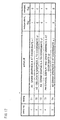
- Fig. 17 is an explanatory diagram illustrating a specific example of the synchronization timing information.
- the video reproducing section 20 interrupts the program executing section 10 at such a timing that each of values respectively indicated by fields timing of the entries whose entry numbers are 1 through 5 coincide with a value of the clock 23.
- the interruption is carried out in order from (i) interruption corresponding to the entry having the entry number 1, to (ii) interruption corresponding to the entry having entry number 5.
- the entry whose entry number is 3 has a field merged_flag indicative of "1", so that no interruption corresponding to the entry number 3 is carried out.
- the entry sync_info(1) has a field timing indicating a value corresponding to time coming before the time point T1, and has a field independent_flag indicative of "1".
- the entry sync_info(2) has a field independent_flag indicative of "0”, and has a field merged_flag indicative of "0". Therefore, in the interruption rerun process, interruption corresponding to the entry sync_info(1) and interruption corresponding to the entry sync_info(2) are carried out in this order.
- the entry sync_info(3) has a field merged_flag indicative of "1", so that interruption corresponding to the entry sync_info(3) is carried out in the interruption rerun process.
- the entry sync_info(3) does not require a process of relocating the graphics A, which process is required by the entry sync_info(2). Accordingly, the interruption corresponding to the entry sync_info(3) is executed with throughput lower than that in the case where the interruption corresponding to the entry sync_info(1) and the interruption corresponding to the entry sync_info(2) are carried out in this order. This makes it possible to shorten time required in actually starting the reproduction from the time point T.
- the entry sync_info(4) has an field independent_flag indicative of "1". Therefore, interruption corresponding to the entry sync_info(1), and interruption corresponding to the entry sync_info(2) do not need to be carried out in the interruption rerun process, but only interruption corresponding to the entry sync_info(4) is carried out therein.
- interruption corresponding to the entry sync_info(4), and interruption corresponding to the entry sync_info(5) are carried out in the interruption rerun process.
- the synchronization timing information is contained in the optical disk 2, so that a video clock change occurring until such an arbitrary time in the video data does not need to be produced again for generation of graphics corresponding to the arbitrary time point. This shortens time required in starting the reproduction.
- the field independent_flag is contained in the synchronization timing information, so that time taken for the display of the graphics can be further shortened. Further, the time taken for the display of the graphics can be further shortened by preparing a process allowing acquirement of the result obtained by merging the results of the individual processes.
- a reproducing apparatus of the present invention may be arranged such that: before starting reproduction from a specific time point of content data, synchronization control means respectively transmits regulation control signals in accordance with timing information items respectively including timing specifying information items each indicating a time point coming before the specific time point, in order from a regulation control signal corresponding to a timing specifying information item having a smallest number.
- each timing information item includes dependency information indicating a dependency relation with other timing information items of a timing information aggregation made up of timing information items; and before starting the reproduction form the specific time point of the content data, the synchronization control means checks the dependency information, and respectively transmits synchronization control signals in accordance with timing information items each of which does not depend on the other timing information items, and each of which includes a timing specifying information indicating a time point that comes before the specific time point and that is the closest to the specific time point, the synchronization control signals being sent in order from a regulation control signal corresponding to a timing specifying information item having a smallest number.
- the reproducing apparatus may be arranged such that: a plurality of synchronization executing programs constitute a synchronization executing program aggregation; and the synchronization executing program aggregation includes a synchronization executing program (merged synchronization executing program) which allows an identical result to a result obtained through processes carried out by other synchronization executing programs; and the synchronization executing program aggregation includes merged synchronization executing program identifying information for identifying whether or not a synchronization executing program specified by action specifying information is the merged synchronization executing program; and before starting the reproduction from the specific time, the synchronization control means checks the merged synchronization executing program identifying information, and makes a reference to the merged synchronization executing program so as to respectively transmit synchronization control signals in accordance with timing information items respectively including timing specifying information items each indicating a time point coming before the specific time point, in order from a synchronization control signal corresponding to timing specifying information having a
- the present embodiment is a modified example of Embodiment 1, and allows for "special reproduction” such as high speed reproduction. For this reason, the present embodiment and Embodiment 1 have a lot in common, so that the following description only deals with differences from Embodiment 1.
- the present embodiment has the same system structure as that of Embodiment 1, so that explanation thereof is omitted.
- the present embodiment has the same program executing section as that of Embodiment 1, so that explanation thereof is omitted.
- the present embodiment has the same output control section as that of Embodiment 1, so that explanation thereof is omitted.
- the video reproducing section of Embodiment 1 and that of the present embodiment are substantially the same, but are different from each other in that: in the present embodiment, the synchronization control section 22 monitors a condition of the decoder 24, and transmits the synchronization control signal in accordance with (i) the condition of the decoder 24 and (ii) execution condition information (below-mentioned field condition()).
- the synchronization timing information contains the execution condition information indicating the condition in which the decoder 24 is when the synchronization executing program should be executed.
- the synchronization control section 22 always monitors the reproduction condition (e.g., normal reproduction, high speed reproduction, reverse reproduction, and slow reproduction) of the decoder 24, and determines in accordance with the reproduction condition whether or not interruption corresponding to each of entries contained in the synchronization timing information is carried out. Specifically, in cases where, e.g., a field normal of the entry is indicative of "1", the synchronization control section 22 determines, in reference to below-mentioned fields normal, FF, FR, SF, and SR of the entry, that interruption is carried out during the normal reproduction. Meanwhile, in cases where the field FF is indicative of "1", the synchronization control section 22 determines, in reference to the fields, that interruption is carried out during the high speed reproduction.
- the reproduction condition e.g., normal reproduction, high speed reproduction, reverse reproduction, and slow reproduction
- FIG. 18 is an explanatory diagram illustrating the data structure of the synchronization timing information.
- each of the entries sync_info() is made up of four fields: timing, target, action_id, and condition().
- the fields timing, target, and action_id are the same as those of Embodiment 1, so that explanation thereof is omitted.
- the entries sync_info() contained in the synchronization timing information be arranged in order of values of respective fields timing of the entries.
- the field condition() (execution condition information) is made up of the sub fields: normal, FF, FR, SF , and SR .
- the sub field normal indicates whether or not interruption corresponding to the entry sync_info() including the sub field normal is carried out. Specifically, in cases where the sub field normal is indicative of "1", the interruption is carried out. On the other hand, in cases where the sub field normal is indicative of "2", no interruption is carried out.
- the sub field FF indicates whether or not interruption is carried out during forward high speed reproduction.
- the sub field FR indicates whether or not interruption is carried out during reverse high speed reproduction.
- the sub field SF indicates whether or not interruption is carried out during forward slow speed reproduction.
- the sub field SR indicates whether or not interruption is carried out during reverse slow speed reproduction.
- the interruption process can be selected in accordance with the reproduction condition.
- the reproducing apparatus of the present invention may be arranged such that: the timing information contains the execution condition information indicating the condition, in which the synchronization executing program should be executed, of the decoding means. Moreover, the reproducing apparatus of the present invention may be arranged such that: the synchronization control means monitors the condition of the decoding means, and transmits the synchronization control signal in accordance with the condition of the decoding means and the execution condition information.
- Fig. 19 is a functional block diagram schematically illustrating a structure of a video disk player 1' according to the present arrangement.
- the video disk player 1' (reproducing apparatus) is an apparatus for reproducing AV data stored in an optical disk 2. As shown in Fig. 19 , the video disk player 1' includes a user input section 3, a video reproducing section 20, a combining section 30, a disk reading section 50, a program executing section 70, a general control section (general control means; notifying means) 80, and a switching section (switching means) 90.
- a user input section 3 As shown in Fig. 19 , the video disk player 1' includes a user input section 3, a video reproducing section 20, a combining section 30, a disk reading section 50, a program executing section 70, a general control section (general control means; notifying means) 80, and a switching section (switching means) 90.
- the disk reading section 50 reads out video data (content data), programs (synchronization executing programs), synchronization timing information, and program management information from the optical disk 2 (content recording medium).
- the disk reading section 50 sends each of the programs to the program executing section 70, and sends the video data and the below-mentioned synchronization timing information to the video reproducing section 20, and sends the program management information to the general control section 80.
- the user input section 3 is a section via which the user manipulates the video disk player 1'. Specifically, the user input section 3 corresponds to a remote controller, and a button provided in a front panel of the device.
- the user input section 3 generates manipulation information (user input manipulation information; reproduction control information), and sends the manipulation information to the general control section 80. Examples of the user manipulation include: (i) reproduction control manipulation such as reproduction start manipulation and suspending manipulation; (ii) menu manipulation such as menu calling-up manipulation, manipulation of returning from the menu to the content; and (iii) GUI manipulation such as manipulation of moving a cursor in all the directions, and determining manipulation.
- the general control section 80 carries out general control over the video disk player 1'. Specifically, the general control section 80 controls the program executing section 70 and the switching section 90 in accordance with the program management information read out by the disk reading section 50. Further, the general control section 80 transfers, to the program executing section 70 and the switching section 90, a user input sent from the user input section 3.
- the program executing section 70 executes the program. Specifically, the program executing section 70 executes the program so as to control the video reproducing section 20 via the disk reading section 50 and the switching section 90. Moreover, the program executing section 70 executes the program so as to generate bitmap data, and sends the generated bitmap data to the combining section 30. Note that, in the present arrangement, the program executed by the program executing section 70 is not limited to such a program for generating the output data.
- the switching section 90 carries out switching between targets from which reproduction control information to be sent to the video reproducing section 20 is supplied. Specifically, the switching section 90 selects, in accordance with the control (reproduction control switching information) carried out by the general control section 80, either one of (i) reproduction control information sent from the general control section 80 and (ii) reproduction control information sent from the program executing section 70. Then, the switching section 90 sends the selected reproduction control information to the video reproducing section 20.
- the video reproducing section 20 decodes the video data sent from the disk reading section 50, and sends the decompressed video data to the combining section 30. Further, the video reproducing section 20 controls the program executing section 70 in accordance with the synchronization timing information sent from the disk reading section 50.
- the combining section 30 combines (i) the bitmap data sent from the program executing section 70, with (ii) the decompressed video data sent from the video reproducing section 20. Then, the combining section 30 outputs an image (combined image) obtained by the combining.
- Fig. 20 is a function block diagram fully illustrating a structure of the program executing section 70.
- the program executing section 70 executes the program in accordance with the synchronization control signal received from the synchronization control section 22. Specifically, the program executing section 70 executes the program specified by a field action_id contained in the synchronization control signal received from the synchronization control section 22. Particularly in the present arrangement, the program executing section 70 executes the program for generating the image data to be overlaid with the video image.
- the program executing section 70 is made up of a memory 11, a CPU 12, a video reproduction control section 13, an interrupt control section 14, a user input control section 15, an interface 16, and a disk reading control section 17.
- the memory 11 temporarily stores the program sent from the disk reading section 50.
- the CPU 12 reads out the program stored in the memory 11, and executes the program. In accordance with how the program runs, the CPU 12 sends an instruction to the video reproduction control section 13, or sends the bitmap data to the combining section 30.
- the video reproduction control section 13 sends a control signal to the video reproducing section 20 in accordance with the program thus executed.
- the control signal include: (i) a control signal for controlling the reproduction such as reproduction start and reproduction suspending, and (ii) a control signal for acquiring a state such as current reproduction time.
- the interrupt control section 14 receives an interrupt from outside of the program executing section 70, and sends the interrupt to the CPU 12.
- the CPU 12 launches an interrupt handler upon the reception of the interrupt from the interrupt control section 14. Note that various types of information supplied from the member having sent the interrupt are stored in a register (not shown) of the interrupt control section 14.
- the user input control section 15 receives, as the interrupt, the user input information transferred from the general control section 80, and sends the interrupt to the CPU 12.
- the CPU 12 launches the interrupt handler upon the reception of the interrupt from the user input control section 15. Note that various types of information supplied by way of the interruption are stored in a register (not shown) of the user input control section 15.
- the interface 16 serves as an interface between the general control section 80 and the program executing section 70. Via the interface 16, the general control section 80 instructs the program executing section 70 to read out and execute the program. In the meanwhile, when the execution of the program is finished, the program executing section 70 notifies the general control section 80 that the execution of the program is finished.
- the disk reading control section 17 controls the disk reading section 50 in accordance with an instruction sent from the CPU 12.
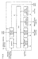
- Fig. 21 is a functional block diagram fully illustrating a structure of the general control section 80.
- the general control section 80 carries out general control over the video disk player 1' in accordance with the program management information read out by the disk reading section 50.
- the general control section 80 is made up of a memory 81, a user input control section 82, a CPU 83, a disk reading control section 84, a switching control section 85, a video reproduction control section 86, and a program execution control section 87.
- the memory 81 temporarily stores the program management information sent from the disk reading section 50.
- the CPU 83 reads out the program management information stored in the memory 81. In accordance with the program management information thus read out, the CPU 83 sends an instruction to each of the user input control section 82, the disk reading control section 84, the switching control section 85, the video reproduction control section 86, and the program execution control section 87.
- the user input control section 82 simultaneously sends, to the program executing section 70 and the CPU 83, the user input sent from the user input section 3.
- the CPU 83 interprets the user input in accordance with the program management information so as to control the program execution control section 87 and the video reproduction control section 86.
- the disk reading control section 84 controls the disk reading section 50 in accordance with the instruction sent from the CPU 83.
- the switching control section 85 controls the switching section 90 in accordance with the instruction sent from the CPU 83.
- the video reproduction control section 86 sends an control signal to the video reproducing section 20.
- the control signal includes: (i) a control signal for specifying video data to be reproduced; (ii) a control signal for starting the readout; (iii) a control signal for starting the decoding; (iv) a control signal for ending the decoding; (v) a control signal for jumping to either a preceding chapter or a subsequent chapter; and (vi) a control signal for starting high speed reproduction.
- the program execution control section 87 sends control information to the program executing section 70 in accordance with the instruction sent from the CPU 83.
- the video reproducing section 20 of the present arrangement is substantially the same as that of Embodiment 1; however, they are different in that the video reproducing section 20 of the present arrangement includes no output control section 40. Therefore, the video reproducing section 20 of the present arrangement does not control the output side buffer switching section 43 via the synchronization control section 22, unlike the one shown in Fig. 4 .
- the program management information is made up of various types of information required by the general control section 80 for the purpose of controlling the program execution.
- One program management information item is prepared for one program.
- All the program information items stored in the optical disk 2 are stored in a program management table shown in Fig. 22(a) . Indicated by number_of_pmi is the number of the program management information items stored in the program management table. Note that a first entry of the program management table indicates a program to be automatically executed in response to insertion of the optical disk 2.
- Fig. 22(b) is an explanatory diagram illustrating a data structure of the program management information.
- the program management information is made up of fields program_file_name, playback_control_mode, is_video_specified, video_file_name, start_mode, resume_flag, and menu_flag.
- the field program_file_name (program specifying information) is a field for specifying the filename of a file storing the program.
- the field playback_control_mode is a flag indicating whether or not a user input corresponding to the reproduction control manipulation is sent from the general control section 80 to the video reproducing section 20. In cases where the reproduction control manipulation is not sent thereto, the playback_control_mode is set at "0". On the other hand, in cases where the reproduction control manipulation is sent thereto, the playback_control_mode is set at "1". Such a flag allows a content creator to select whether (i) responsiveness to the reproduction control manipulation carried out by the user is taken into great consideration, or (ii) freedom in the program takes priority over the responsiveness. This will be described later.
- the field is_video_specified is a flag indicating whether or not video data to be reproduced concurrently with the execution of the program is specified. In cases where the video data is not specified, the field is_video_specified is set at "0". On the other hand, in cases where the video data is specified, the field is_video_specified is set at "1". In cases where the flag is indicative of "1", the field video_file_name and the field start_mode come after the field is_video_specified.
- the field video_file_name (content data specifying information) is a field for specifying the filename of the video data file to be reproduced concurrently with the execution of the program.
- the field video_file_name exists only when the field is_video_specified is indicative of "1".
- the video data and the synchronization timing information can be read out from the optical disk 2 prior to the execution of the program. Accordingly, time required in starting the reproduction of the video data can be shortened. This will be explained later.
- the field start_mode (reproduction start instruction necessity information) is a flag indicating whether (i) display of the video data specified by the field video_file_name will be started by an instruction contained in the program specified by the field program_file_name, or (ii) the display of the video data will be started irrespective of the program. In cases where the display of the video data specified by the field video_file_name will be started by the instruction contained in the program, the field start_mode is set at "0". On the other hand, in cases where the display of the video data will be started irrespective of the program, the field start_mode is set at "1". As described above, the field start_mode exists only when the field is_video_specified is indicative of "1".
- the field menu_flag is a flag indicating whether or not the program specified by the program management information containing the field menu_flag is a "menu content".
- the menu content refers to a content obtained by executing the program in response to the menu calling-up manipulation carried out by the user. In cases where the program is such a program that corresponds to the menu content, the field menu_flag is indicative of "1". Otherwise, the field menu_flag is indicative of "0".
- the field resume_flag (resuming capability information) is a flag indicating whether or not the program specified by the program management information containing the field resume_flag corresponds to a target content to be resumed.
- the wording "resuming (resume)" refers to a function for resuming reproduction of a content from a point at which previous reproduction thereof was suspended due to the menu readout carried out by the user. The reproduction of the content is resumed when the user carries out manipulation of returning from the menu to the previous reproduction condition.
- the field resume_flag is indicative of "1". Otherwise, the field resume_flag is indicative of "0". A reason why such a flag is required is explained as follows.
- contents are classified into the following two types (1) and (2): (1) a content in which the program is executed in synchronization with the video reproduction, and (2) a content in which the program is executed not in synchronization with the video reproduction.
- a specific example of the content (2) is a content in which video is reproduced as a part of a game program.
- the content (1) (former one) can be resumed with ease; however, it is difficult to resume the content (2).
- the flag resume_flag is provided so as to allow the general control section 80 to easily distinguish the contents (1) and (2). This makes it possible that: a content which cannot be resumed by using the resuming function never becomes a target to be resumed, and the user is notified that the content cannot be resumed.
- Fig. 23 is an explanatory diagram illustrating data allocation in the optical disk 2.
- the optical disk 2 is made up of a management information region 61 and a video data region (content data storing region) 62.
- the management information region 61 is made up of (i) a program management information storing region 61c storing the program management table, (ii) a program storing region (synchronization program storing region) 61A storing the programs, and (iii) a synchronization timing information storing region 61B storing the synchronization timing information.
- the video data region 62 stores the video data. Note that the program management table, the synchronization timing information, the programs, and the video data are managed as files, individually.
- the program management information is collectively stored in the program management information storing region 61C of the optical disk 2, in the form of the program management table. All the program management information is firstly read out in response to the insertion of the optical disk 2, so that seeking time, etc., required for the readout of the program management information can be shortened.
- Fig. 24 is a flowchart illustrating an entire flow of the reproducing process carried out by the general control section 80 of the video disk player 1'.
- the video disk player 1' is powered ON, and then file system information (not shown) is read out from the optical disk 2, and initialization of the respective processing sections is carried out (S61).
- the program management table is read out from the program management information storing region 61C, and the program management table thus read out is stored in the memory 81 (S62).
- the first one of the program management information in the program management table stored in the memory 81 is selected as "current program management information".
- the switching section 90 Carried out next is a setting of the switching section 90 (S63). Specifically, in cases where the field playnback_control_mode of the current program management information is indicative of "1", the switching section 90 is so set as to transfer, to the video reproducing section 20, (i) the reproduction control information supplied from the general control section 80, and (ii) the reproduction control information supplied from the program executing section 70. On the other hand, in cases where the field playnback_control_mode of the current program management information is indicative of "0", the switching section 90 is so set as to transfer, to the video reproducing section 20, only the reproduction control information supplied from the program executing section 70.
- the general control section 80 issues, to the video reproducing section 20, an instruction for starting the readout and the decoding of the video file (S65).
- the setting is carried out as follows. That is, in cases where the field start_mode is indicative of "0", the setting is carried out such that no display is carried out until the program gives an instruction. On the other hand, in cases where the field start_mode is indicative of "1", the setting is carried out such that the display is carried out upon the completion of the preparation irrespective of the instruction given from the program.
- the general control section 80 issues, to the program executing section 70 via the program executing control section 87, an instruction for executing the program file specified by the field program_file_name (S66).
- the general control section 80 waits for completion of the execution of the program (S67).
- the program management information corresponding to the menu content is set as the current program management information, and then the sequence jumps to the step S63.
- a search for the program management information corresponding to the menu content is carried out by searching for the program management information which has the field menu_flag indicating "1", and which is stored in the program management table of the memory 81.
- a menu calling-up instruction is sent from the user input section 3 to the general control section 80.
- the general control section 80 thus having received the menu calling-up instruction checks the field resume_flag of the program management information corresponding to the content currently being reproduced (S71). In cases where the field resume_flag is indicative of "0", the user is notified that the resuming cannot be carried out (S76). Then, the general control section 80 issues a reproduction halt instruction to the video reproducing section 20 (S77).
- a halt instruction is issued to the video reproducing section 20 (S72). Further, an instruction is issued so that a current value of the clock 23 (see Fig. 4 ) of the video reproducing section 20 is stored in a register (resuming register; not shown) (S73). Further, the general control section 80 sets "resuming target program management information" as the current program management information (S74).
- the general control section 80 issues a halt instruction to the program executing section 70 (S75).
- the general control section 80 sets, as the current program management information, the program management information corresponding to the menu content. Then, the menu content is executed in accordance with the processes of the steps S63 through S66 shown in Fig. 24 .
- the general control section 80 sets, as the current program management information, the program management information set as the resuming target program management information (S81).
- the general control section 80 instructs the program executing section 70 to specify the field program_file_name contained in the current program management information, and to execute the program specified by the field program_file_name (S82).
- the general control section 80 instructs the video reproducing section 20 to (i) set, as the reproduction start time point T, the value stored in the resuming register, and (ii) execute the interruption rerun process explained in Embodiment 2 with reference to Fig. 16 (S83).
- the general control section 80 instructs the video reproducing section 20 to start the reproduction from the point corresponding to the value stored in the resuming register (S84). This allows realization of the resuming process.
- the general control section 80 issues, to the video reproducing section 20, an instruction for (i) deleting the value stored in the resuming register, and (ii) canceling the setting in the resuming target program management information.
- the field playback_control_mode is set at "1", for attainment of faster responsiveness to the reproduction control manipulation. Further, the video data to be reproduced is determined in advance, so that the field is_video_specified is set at "1". Further, there is the program to be executed in synchronization with the video reproduction, so that the video reproduction needs to be started after the execution of the program starts. For this reason, the field start_mode is set at "0".
- the general control section 80 carries out the initializing during a period of time from time point T11 to time point T12. Then, the general control section 80 instructs the video reproducing section 20 to start the video reproduction, and instructs the program executing section 70 to start the program execution. From the time point T12, the video reproducing section 20 starts to read out and decode the video data. At time point T13, the preparation for the video display is completed.
- the program executing section 70 reads out the program, and prepares for the execution of the program, and starts executing the program. At time point T14 from which the video reproduction starts, the program executing section 70 that is executing the program issues a video reproduction start instruction to the video reproducing section 20.
- the video reproducing section 20 sends, to the program executing section 70, an interrupt for indicating the end of the video reproduction.
- the interrupt handler in the program causes a program ending process to be carried out, with the result that the end of the execution of the program is notified to the general control section 80.
- the structure of the present arrangement makes it possible that the program executing section 70 and the video reproducing section 20 carry out concurrently the program execution preparation and the video data reproduction preparation, respectively. Accordingly, time required in starting the video reproduction is shortened as compared with that in the conventional technique.
- the video reproduction can be started before the completion of the program execution preparation. Therefore, by setting the start_mode at 1, latency time between the time point T13 and T14 can be eliminated. Accordingly, the video reproduction can be started more quickly.
- the user carries out reproduction control manipulation "Reproduce from the next chapter".
- the reproduction control manipulation is sent to the general control section 80, and then is sent directly from the general control section 80 to the video reproducing section 20, i.e., is not sent thereto via the program executing section 60. This makes it possible that the overhead due to the execution of the program becomes small, with the result that the responsiveness to the user's manipulation is improved.
- a specific example of a program-based content in which video to be reproduced is just a part of the content is a game. See the following example of a setting of the program management information of such a program-based content:
- the field playback_control_mode is set at "0" such that the program freely controls the video reproduction.
- the video data to be reproduced depends on how the program runs, so that the video data to be reproduced is not determined in advance. For this reason, the field is_video_specified is set at "1".
- the data structure in the present arrangement is a data structure in which the field video_file_name of the program management information can specify only one filename; however, the data structure may be a data structure in which the field video_file_name thereof can specify a plurality of filenames.
- the order of the filenames specified by the field video_file_name corresponds to the order of data to be reproduced.
- the video reproducing section 20 can start to read out, decode, and reproduce the next video data. This allows such an additional effect that an interlude is short between the reproduction of the video data and the reproduction of the next video data of the content having such a plurality of video data to be reproduced continuously.
- a warning is given so as to notify that the reproduction of the content cannot be resumed.
- a warning may be given in response to a manipulation other than the menu calling-up, such as an attempt of the resuming.
- the general control section 80 simultaneously issues (i) the reproduction preparation start instruction to the video reproducing section 20, and (ii) the program execution start instruction to the program executing section 70.
- the issuing is not necessarily carried out simultaneously.
- the video reproducing section 20 is not used during reproduction of a content which consists of a program and which does not have any video data to be reproduced.
- the video reproduction preparation for the content coming just after the content is caused to start during the reproduction of the content consisting of the program. Accordingly, the latency time required in starting the video reproduction can be further shortened.
- a flag indicating whether or not the program specified by the field program_file_name of the program management information causes the video reproduction to be carried out may be added such that the general control section 80 can easily judge whether or not the program causes the video reproduction to be carried out.
- the video reproducing section 20 is instructed to start reading out and decoding the video data file; however, the disk reading section 50 may be instructed to start reading out the video data file, instead.
- the readout of the video data from the optical disk 2 can be carried out concurrently with the program execution preparation, with the result that the video reproduction can be started more quickly.
- the general control section 80 interprets and transmits the various types of information contained in the program management information; however, another function block such as the program executing section 70 may interpret and transmit the various types of information.
- the program management information corresponding to a program ⁇ is stored in another program b . Therefore, just before executing the program a , the program executing section 70 interprets and transmits the program management information which corresponds to the program a , and which is contained in the program b This makes it possible to realize the same function as that in the case where the general control section 80 carries out the interpretation and the transmission.
- the feature of the present invention lies in that program management information relevant to a program is stored in a place irrelevant to the program.
- the program management information corresponding to the program is stored in the different program.
- the program management information is allocated to a place other than any programs. Such allocation allows the following additional effect: no works such as rewriting of an existing program and re-compiling are required even when changing the order in which the programs are executed.
- the present arrangement assumes that an entire part of one video data is reproduced by executing a program; however, a part of the video program can be reproduced.
- a field indicating reproduction start time and reproduction end time of the video data is added to the program management information. This makes it possible to reproduce various parts of one video data.
- the switching control section 85 and the switching section 90 are provided in the present arrangement, however, the switching control section 85 and the switching section 90 are not required when handling only the video-based content. Even in this case, the program can be executed in synchronization with the video reproduction. Moreover, in this case, overhead is never caused by the program in response to the reproduction control manipulation. This attains the effect of the present invention, i.e., the responsiveness to the user's reproduction control manipulation is improved.
- the video reproducing section 20 send, to the program executing section 70, the interrupt indicating the end of the video reproduction; however, the video reproducing section 20 may directly notify the general control section 80 that the video reproduction is finished.
- the following procedures are carried out upon the end of the video reproduction: the end of the video reproduction is notified to the general control section 80, and the general control section 80 issues a program execution ending instruction to the program executing section 70 in response to the notification.
- the notification may be given to either the program executing section 70 or the general control section 80, depending on whether the content is the video-based content or the program-based content.
- FIG. 18 Another embodiment of the present invention will be explained below with reference to Fig. 18 .
- the present embodiment is similar to arrangement 1, so that only difference therebetween is explained.
- the present embodiment has the same data structure as the data structure shown in Fig. 18 . However, meanings respectively rendered to the fields are different as follows.
- a value ALWAYS which does not specify an interrupt timing is defined in the field timing.
- the sub fields in the field condition() are interpreted as interruption execution conditions, respectively. For example, in cases where the sub field normal is indicative of "1", interruption is carried out in accordance with the entry sync_info() containing the sub field normal, at the moment at which the synchronization control section 22 is brought into the normal reproduction state from the other reproduction state.
- the synchronization control section 22 checks the entry sync_info() in which the field timing has a value corresponding to the value ALWAYS, and carries out the interruption in accordance with the value of the field condition().
- Such a structure makes it possible to carry out the process in accordance with the change of the reproduction state. For example, a special graphics is displayed only during the fast-forwarding. This allows the user to enjoy the content repeatedly, with the result that an additional value of the content is improved.
- the process is carried out in the reproduction state resulted from the change of the reproduction state.
- the process may be carried out in a reproduction state selected before the change of the reproduction state.
- the process may be carried out in each of the reproduction states.
- the video data is directly referred in accordance with the program and the program management information; however, the present invention is not limited to this.
- the video disk player may make a reference to either (i) video data management information containing various types of information concerning the video data, or (ii) play list information indicating an order in which the video data is reproduced. Examples of the various types of information concerning the video data include: attribution information, random access information, and the like.
- the video data, the synchronization timing information, and the program are stored in the optical disk; however, the video data, the synchronization timing information, and the program may be stored in either (i) another recording medium such as a hard disk, or (ii) another recording medium connected to the video disk player via a network.
- the program and the synchronization timing information are managed by using different files, respectively; however, the program and the synchronization timing information may be managed by using the same file.
- the synchronization timing information is sent from the program executing section to the video reproducing section, unlike the foregoing embodiments. Accordingly, the number of files to be read out is reduced, with the result that the overhead is reduced. This is an additional effect.
- the outputs respectively sent from the program executing section and the video reproducing section i.e., the outputs to be combined together are images; however, a structure similar to the above structure is applicable to the case of combining sounds (audio).
- the program executing section executes a versatile program; however, the present invention is not limited to this.
- the program executing section is a process section having a single function such as a function of carrying out a still image slide show reproduction
- the effects of the present invention can be exhibited.
- the effects of the present invention also can be exhibited even when the program executing section is a WEB browser and deals with a combination of the HTML (Hyper Text Markup Language) and the ECMA Script.
- each of the processes executed by the program (synchronization executing program) and the interrupt handler is a process of outputting an image; however, the process may be any process executed at a certain timing in synchronization with the reproduction of the video data.
- the process excludes a process of using the output control section for the purpose of carrying out output control of an image and a sound each generated by the program executing section.
- a specific example of the process includes: (i) a process of (a) reading out data from the recording medium and (b) writing data therein; (ii) a process of making access to a network; or (iii) a process of incrementing a variable in the program.
- the program executing section and the output control section are controlled in accordance with the synchronization timing information; however, both the program executing section and the output control section are not necessarily controlled in accordance with the synchronization timing information.
- the control can be carried out at a frame rate, even when only the output control section is controlled in accordance with the synchronization timing information and when the program executing section uses an individual clock so as to set a timing at which the bitmap image is generated. Further, even when no output control section is provided and only the program is executed, no overhead occurs due to the polling process.
- the foregoing embodiments assume that the program executing section and the output control section are targets to be controlled; however, the combining section may be the target to be controlled.
- the control over the combining section is a control of changing an order of display planes; or the like.
- Fig. 28 is an example of another structure of the video disk player 1.
- the output control section switches the images generated by using the program executing section; however, the present invention is applicable to any structure as long as the image outputting and the sound outputting are controlled in accordance with the synchronization timing information.
- Fig. 28 illustrates one example of such a structure.
- the video reproducing section 20 receives data obtained by multiplexing bitmap data with video data, and outputs decompressed video data and the bitmap data. Therefore, the video reproducing section 20 includes two decoders: (i) a decoder for generating the decompressed video data, and (ii) a decoder (output generating means) for generating the bitmap data (second output data).
- the decoders operate in accordance with a clock generated by the clock 23. Further, the output control section 40 controls the outputting of the bitmap data, which outputting is carried out by the video reproducing section 20. Moreover, the output control section 40 causes the synchronization timing information to be supplied from the program executing section 10 to the video reproducing section 20. Such a structure makes it possible to control, at the video frame precision, the outputting of the bitmap data generated by using the program.
- the foregoing embodiment uses the two display buffer memories; however, the present invention is not limited to this.
- the effects of the present invention can be exhibited even when using one or not less than three display buffers.
- one block i.e., the program executing section is used to output the image concurrently with the video reproducing section; however, the effects of the present invention can be exhibited even when a plurality of image outputting blocks are used.
- the video reproducing section carries out the control in accordance with the synchronization timing information; however, the present invention is not limited to this.
- the effects of the present invention can be exhibited as long as a component using the same clock as that of the video reproducing section is used.
- the value of the field merged_flag of the entry sync_info() is set at "1" so as to specify a merged synchronization executing program allowing the same result as a result obtained by executing a plurality of synchronization executing programs; however, the present invention is not limited to this.
- the value of the field merged_flag may be set so as to specify either (i) a program for displaying a warning, or (ii) a program for displaying, when starting the reproduction from a certain point of the video, a graphics different from a graphics displayed when starting the video from the beginning.
- the reproducing apparatus of the present invention may be arranged such that: the data acquiring means acquires an arbitrary-point reproduction synchronization executing program, which is executed only when starting reproduction from a certain point of the content data, and the synchronization timing information including the timing specifying information includes (i) an action specifying information item indicating a synchronization executing program to be executed, and (ii) an arbitrary-point reproduction synchronization executing program identifying information item (e.g., setting a value other than "1" at the field merged_flag) indicating whether or not the synchronization executing program specified by the action specifying information is the arbitrary-point reproduction synchronization executing program, and for starting reproduction from a certain point of the content data, the synchronization control means transmits the synchronization control signals in accordance with (I) a synchronization timing information item that includes a timing specifying information item indicating a time point which comes before but is closest to a time point from which the reproduction is started, and that includes an arbitrary-point reproduction synchron
- the reproducing apparatus of the present invention may include the first output generating section and the second output generating section, and the means for controlling outputting of the second generating section in accordance with the synchronization timing information and the clock of the first output generating section.
- the reproducing apparatus of the present invention may be arranged such that the synchronization timing information is separated from the information for use in generating the output of the first output generating section.
- the reproducing apparatus of the present invention may be arranged such that the synchronization timing information at least include (i) information indicative of a time point in a time period of the first output generating section, and (ii) either one of (a) information indicative of a control target or (b) information indicative of what control is to be carried out.
- the reproducing apparatus of the present invention may be arranged such that: the first output generating section is a video reproducing section, and the second output generating section is a program executing section.
- the reproduction method of the reproducing apparatus which includes the first output generating section and the second output generating section, of the present invention may include: (i) a step of comparing the synchronization timing information with the clock of the first output generating section; and (ii) a step of outputting the control signal in accordance with the comparison result.
- the recording medium of the present invention may be a recording medium which stores (i) the information for use in generating the output of the first output generating section; (ii) the information for use in generating the output of the second output generating section; and (iii) the synchronization timing information for controlling the outputting of the second output generating section in accordance with the clock of the first output generating section.
- the recording medium of the present invention may be arranged such that the timing information is stored in the vicinity of the information for use in generating the output of the second output generating section.
- the recording medium of the present invention may be arranged such that the timing information and the program are stored in the same file.
- each of the video disk players 1, 1' and 1" may be constituted by hardware logic, or by software with the use of a CPU as follows.
- each of the video disk players 1, 1', and 1" has: (i) the CPU (central processing unit) for executing an instruction of a control program realizing various functions; (ii) a ROM storing the program; (iii) a RAM for expanding the program; (iv) a storage device (storage medium) such as a memory storing the program and various data; and (v) the like.
- the object of the present invention also can be achieved by (i) providing, for each of the video disk players 1, 1', and 1", a storage medium storing, in a computer readable manner, a program code (executable program; intermediate code; source program) of the control program for the video disk players 1, 1', and 1", and (ii) causing a computer (CPU or MPU) to read and execute the program code stored in the storage medium, the program code being the software realizing the aforementioned functions.
- a computer CPU or MPU
- Examples of the storage medium are: (i) tapes such as a magnetic tape and a cassette tape; (ii) magnetic disks such as a floppy® disk and a hard disk; (iii) optical disks such as a CD-ROM (compact disk read only memory), a magnetic optical disk (MO), a mini disk (MD), a digital video disk (DVD), and a CD-R (CD-Rewritable); (iv) cards such as an IC card (inclusive of a memory card) and an optical card; and (v) semiconductor memories such as a mask ROM, an EPROM (electrically programmable read only memory), an EEPROM (electrically erasable programmable read only memory), and a flash ROM.
- tapes such as a magnetic tape and a cassette tape
- magnetic disks such as a floppy® disk and a hard disk
- optical disks such as a CD-ROM (compact disk read only memory), a magnetic optical disk (MO), a mini disk (MD),
- Each of the video disk player 1, 1', and 1" may be connectable to the communication network, and the program code may be supplied via the communication network.
- the communication network is not particularly limited. Specific examples thereof are: the Internet, Intranet, Extranet, LAN (local area network), ISDN (integrated services digital network), VAN (value added network), CATV (cable TV) communication network, virtual private network, telephone network, mobile communication network, satellite communication network, and the like. Further, the transmission medium constituting the communication network is not particularly limited.
- the present invention can be realized by (i) a carrier wave realized by electronic transmission of the program code, or (ii) a form of a series of data signals.
- a reproducing apparatus includes: data acquiring means for acquiring content data and synchronization timing information items; clock generating means for generating a clock signal; decoding means for converting, in accordance with the clock signal, the content data into reproduction data for reproduction output; synchronization control means for transmitting synchronization control signals to synchronization processing means, in accordance with the clock signal, at timings specified by timing specifying information items included in the synchronization timing information items, respectively; and the synchronization processing means for carrying out a process in accordance with each of the synchronization control signals received from the synchronization control means.
- a method, for controlling a reproducing apparatus including data acquiring means, decoding means, and synchronization processing means includes the steps of: causing the data acquiring means to acquire content data and synchronization timing information; causing the decoding means to (i) convert, in accordance with the clock signal, the content data into reproduction data for reproduction output, and (ii) send a synchronization control signal to the synchronization processing means in accordance with the clock signal at a timing specified by timing specifying information included in the synchronization timing information; and causing the synchronization processing means to carry out a process in accordance with the synchronization control signal.
- the above arrangements make it possible to supply, to the synchronization processing means, the synchronization control signal (trigger) that specifies the timing at which the process is carried out.
- the supply of the synchronization control signal is carried out in synchronization with the reproduction process that the decoding means carries out with respect to the content data.
- examples of the "process" to be carried out by the synchronization processing means include: a process of controlling data outputting, a process of executing a program, and the like.
- the other examples of the "process” include: a process of making access to a network, a process of reading out from and writing in a recording medium, and the like.
- the reproducing apparatus may be arranged such that: the data acquiring means further acquires synchronization executing programs, and the synchronization processing means includes program executing means for executing each of the synchronization executing programs in accordance with the synchronization control signal received from the synchronization control means.
- the above arrangement makes it possible to supply, to the synchronization processing means, the synchronization control signal (trigger) that specifies the timing at which the output data is generated by executing the synchronization executing program.
- the supply of the synchronization control signal is carried out in synchronization with the reproduction process that the decoding means carries out with respect to the content data.
- the synchronization processing means does not need to check the reproduction clock of the decoding means, so that no load is imposed for the synchronization on the synchronization processing means. This makes it possible to effectively execute a program in synchronization with reproduction of AV data or the like.
- the reproducing apparatus may further include: output generating means for generating second output data which is an output other than the reproduction data, wherein: the synchronization processing means includes output control means for controlling outputting of the second output data in accordance with the synchronization control signal received from the synchronization control means.
- the above arrangement makes it possible to control the outputting of the second output data which is outputted in synchronization with the reproduction process that the decoding means carries out with respect to the content data.
- the examples of the "second output data" generated by the output generating means include: (i) graphics data generated by executing a program, and (ii) data obtained by decoding bitmap data multiplexed in the video data.
- the second output data is not limited to such a visual information output. That is, the other examples of the "second output data" include an auditory information output such as (i) audio data generated by executing a program, and (ii) data obtained by decoding audio data multiplexed in video data.
- the synchronization processing means does not need to check the reproduction clock of the decoding means, so that no load is imposed for the synchronization on the synchronization processing means. This allows the reproducing apparatus to efficiently control outputting of AV data in synchronization with reproduction of different AV data or the like.
- the clock does not need to be checked by using the software constituting the synchronization processing means, so that no overhead occurs due to the process. This makes it possible to coincide the timings at a frame rate. In other words, high-precision control can be carried out.
- the arrangement is excellent also in terms of process efficiency.
- the reproducing apparatus may be arranged such that the synchronization processing means executes the synchronization executing program so as to generate output data, and outputs the output data in accordance with the synchronization control signal received from the synchronization control means.
- the above arrangement makes it easier to display a graphics, by using the synchronization executing program, in synchronization with the reproduction process that the decoding means carries out with respect to the content data. Moreover, the above arrangement makes it possible to efficiently carry out the display of the graphics.
- the reproducing apparatus may be arranged such that: the synchronization processing means executes the synchronization executing program, in accordance with the synchronization control signal received from the synchronization control means, so as to generate output data, and outputs the output data.
- the above arrangement makes it easier to display a graphics, by using the synchronization executing program, in synchronization with the reproduction process that the decoding means carries out with respect to the content data. Moreover, the above arrangement makes it possible to efficiently carry out the display of the graphics.
- the reproducing apparatus may be arranged such that: the synchronization processing means includes output control means for controlling the outputting of the output data in accordance with the synchronization control signal received from the synchronization control means, which outputting is caused by the synchronization control program.
- the clock does not need to be checked by using the software constituting the synchronization processing means, so that no overhead occurs due to the process. This makes it possible to coincide the timings at a frame rate. In other words, high-precision control can be carried out.
- the arrangement is excellent also in terms of process efficiency.
- a reproducing apparatus may include: data acquiring means for acquiring content data, a synchronization executing program, and synchronization timing information items; clock generating means for generating a clock signal; decoding means for converting, in accordance with the clock signal, the content data into reproduction data for reproduction output; synchronization control means for transmitting synchronization control signals to synchronization processing means, in accordance with the clock signal, at timings specified by timing specifying information items included in the synchronization timing information items, respectively; and the synchronization processing means for generating output data by executing the synchronization executing program, and for outputting the output data in accordance with each of the synchronization control signals received from the synchronization control means.
- a method, according to the present invention, for controlling a reproducing apparatus including decoding means and synchronization processing means may include the steps of: (a) acquiring content data, a synchronization executing program, and synchronization timing information items; (b) causing the decoding means to (i) convert, in accordance with a clock signal, the content data into reproduction data for reproduction output, and (ii) transmit synchronization control signals to synchronization processing means, in accordance with the clock signal, at timings specified by timing specifying information items included in the synchronization timing information items, respectively; and (c) causing the synchronization processing means to (i) generating output data by executing the synchronization executing program, and (ii) output the output data in accordance with each of the synchronization control signals received from the synchronization control means.
- each synchronization control signal (trigger) that specifies the timing at which the result (output data) obtained by executing the synchronization executing program is outputted.
- the supply of the synchronization control signal is carried out in synchronization with the reproduction process that the decoding means carries out with respect to the content data.
- the synchronization processing means does not need to check the reproduction clock of the decoding means, so that no load is imposed for the synchronization on the synchronization processing means. This makes it possible to effectively execute a program in synchronization with reproduction of AV data or the like.
- the clock does not need to be checked by using the software constituting the synchronization processing means, so that no overhead occurs due to the process. This makes it possible to coincide the timings at a frame rate. In other words, high-precision control can be carried out.
- the arrangement is excellent also in terms of process efficiency.
- a reproducing apparatus may include: data acquiring means for acquiring content data, a synchronization executing program, and synchronization timing information items; clock generating means for generating a clock signal; decoding means for converting, in accordance with the clock signal, the content data into reproduction data for reproduction output; synchronization control means for transmitting synchronization control signals to synchronization processing means, in accordance with the clock signal, at timings specified by timing specifying information items included in the synchronization timing information items, respectively; and the synchronization processing means for generating output data by executing the synchronization executing program in accordance with each of the synchronization control signals received from the synchronization control means, and for outputting the output data.
- a method, according to the present invention, for controlling a reproducing apparatus including decoding means and synchronization processing means may include the steps of: (a) acquiring content data, a synchronization executing program, and synchronization timing information items; (b) causing the decoding means to (i) convert, in accordance with a clock signal, the content data into reproduction data for reproduction output, and (ii) transmit synchronization control signals to synchronization processing means, in accordance with the clock signal, at timings specified by timing specifying information items included in the synchronization timing information items, respectively; and (c) causing the synchronization processing means to (i) generating output data by executing the synchronization executing program in accordance with each of the synchronization control signals received from the synchronization control means, and (ii) output the output data.
- the above arrangement makes it possible to supply, to the synchronization processing means, the synchronization control signal (trigger) that specifies the timing at which the output data is generated by executing the synchronization executing program.
- the supply of the synchronization control signal is carried out in synchronization with the reproduction process that the decoding means carries out with respect to the content data.
- the synchronization processing means does not need to check the reproduction clock of the decoding means, so that no load is imposed for the synchronization on the synchronization processing means. This makes it possible to effectively execute a program in synchronization with reproduction of AV data or the like.
- the clock does not need to be checked by using the software constituting the synchronization processing means, so that no overhead occurs due to the process. This makes it possible to coincide the timings at a frame rate. In other words, high-precision control can be carried out.
- the arrangement is excellent also in terms of process efficiency.
- the data acquiring means may be either (i) means for reading out the content data, the synchronization executing program, and the synchronization timing information from the content recording medium, or (ii) communication means for acquiring the content data, the synchronization executing program, and the synchronization timing information via a network.
- the supply of the video data, the program, and the synchronization timing information to the reproducing apparatus can be carried out in various manners.
- the reproducing apparatus may read out the video data, the program, and the synchronization timing information from the content recording medium.
- any one of the video data, the synchronization executing program, and the synchronization timing information may be acquired via the network, and may be combined with the other data read out from the content recording medium, with the result that the reproduction is carried out.
- a part or all of the synchronization executing programs stored in the content recording medium may be replaced with programs acquired via the network for the sake of the reproduction.
- a part or all of the content data stored in the content recording medium may be replaced with content data acquired via the network for the sake of the reproduction.
- a part or all of the synchronization timing information stored in the content recording medium may be replaced with synchronization timing information acquired via the network for the sake of the reproduction.
- examples of the program include: (i) a program for generating data of an image (still image; animation) to be overlaid with a video image, (ii) a program for outputting only a sound such as a sound effect or narration.
- the reproducing apparatus may be arranged such that: the synchronization processing means includes program executing means for generating output data by executing the synchronization executing program in accordance with the synchronization control signal received from the synchronization control means.
- the above arrangement makes it possible to execute the synchronization executing program in accordance with the synchronization control signal generated in accordance with the clock signal used for the reproduction of the content data. Accordingly, the output data can be generated by executing the synchronization executing program in synchronization with the reproduction of the content data.
- the reproducing apparatus may be arranged such that: the synchronization processing means includes output control means for outputting, in accordance with the synchronization control signal received from the synchronization control means, the output data generated by using the program executing means.
- the above arrangement makes it possible to output, in accordance with the synchronization control signal generated in accordance with the clock signal used for the reproduction of the content data, the output data generated by using the synchronization executing program. Accordingly, the output caused by the synchronization executing program can be controlled in accordance with the reproduction of the content data.
- the reproducing apparatus may be arranged such that: the synchronization timing information items including the timing specifying information items includes action specifying information items, respectively and when respectively transmitting the synchronization control signals to the program executing means at the timings specified by the timing specified information items, the synchronization control means adds, to the synchronization control signals, action specifying information items corresponding to the timing specifying information items, respectively and the program executing means executes a synchronization executing program specified by each of the action specifying information items included in the synchronization control signals received from the synchronization control means.
- the above arrangement allows the synchronization control means to control the synchronization executing program at such a timing that the program executing means carries out the process. This makes it possible that the program executing means switchably executes a plurality of synchronization executing programs (instructions).
- the reproducing apparatus may be arranged such that: for starting reproduction from a certain point of the content data, the synchronization control means transmits, in accordance with synchronization timing information items respectively including timing specifying information items each indicating a time point coming before a time point from which the reproduction is started, the synchronization control signals in order from a synchronization control signal corresponding to earliest one of the time points respectively specified by the timing specifying information items.
- the reproducing apparatus may be arranged such that: each of the synchronization timing information items respectively including the timing specifying information items includes a dependency information item indicating a dependency relation with another synchronization timing information item, for starting reproduction from a certain point of the content data, the synchronization control means transmits the synchronization control signals in accordance with (I) a synchronization timing information item that includes a timing specifying information item indicating a time point which comes before but is closest to a time point from which the reproduction is started, and that includes a dependency information item indicating that the synchronization timing information item is independent from other synchronization timing information items, and (II) synchronization timing information items that include timing specifying information items each indicating a time point which comes after the time point specified by the synchronization timing information item (I), and that include dependency information items respectively indicating that the synchronization timing information items are independent from other synchronization timing information items, the synchronization control signals being transmitted in order from a synchronization control signal corresponding to earliest one of the
- the above arrangement makes it possible to immediately carry out the process when starting the reproduction from the certain point of the content data, so that unnecessary processes do not need to be carried out. This makes it possible to shorten time required in displaying a graphics and starting the reproduction. Examples of the process include: the process of displaying a graphics corresponding to the reproduction start time point, and the like.
- the reproducing apparatus may be arranged such that: the data acquiring means acquires a merged synchronization executing program allowing a result identical to a result obtained by executing a plurality of synchronization executing programs, and each of the synchronization timing information items respectively including the timing specifying information items includes (i) an action specifying information item indicating a synchronization executing program to be executed, and (ii) a merged synchronization executing program identifying information item indicating whether or not the synchronization executing program indicated by the action specifying information item is the merged synchronization executing program, and for starting reproduction from a certain point of the content data, the synchronization control means transmits the synchronization control signals in accordance with (I) a synchronization timing information item that includes a timing specifying information item specifying a time point which comes before but is closest to a time point from which the reproduction is started, and that includes a merged synchronization executing program identifying information item indicating that the synchronization executing program to
- the above arrangement makes it possible to immediately carry out the process when starting the reproduction from the certain point of the content data, so that unnecessary processes do not need to be carried out. This makes it possible to shorten time required in displaying a graphics and starting the reproduction. Examples of the process include: the process of displaying a graphics corresponding to the reproduction start time point, and the like.
- the reproducing apparatus may be arranged such that: the data acquiring means acquires an arbitrary-point reproduction synchronization executing program, which is executed only when starting reproduction from a certain point of the content data, and each of the synchronization timing information items respectively including the timing specifying information items includes (i) an action specifying information item indicating a synchronization executing program to be executed, and (ii) an arbitrary-point reproduction synchronization executing program identifying information item indicating whether or not the synchronization executing program specified by the action specifying information is the arbitrary-point reproduction synchronization executing program, and for starting reproduction from a certain point of the content data, the synchronization control means transmits the synchronization control signals in accordance with (I) a synchronization timing information item that includes a timing specifying information item indicating a time point which comes before but is closest to a time point from which the reproduction is started, and that includes an arbitrary-point reproduction synchronization executing program identifying information item indicating that the synchronization executing program to
- the arrangement makes it possible to select an interruption process in accordance with the reproduction start time point, with the result that a process can be carried out in accordance with the reproduction condition. For example, special graphics is displayed only when starting the reproduction from the certain time point. This allows the user to enjoy the content repeatedly, with the result that an additional value of the content is improved.
- each of the synchronization timing information items includes an execution condition information item indicating a condition in which the decoding means is when the synchronization executing program should be executed
- the synchronization control means monitors the condition of the decoding means, and transmits the synchronization control signal in accordance with (i) the condition of the decoding means and (ii) the execution condition information item.
- the above arrangement makes it possible to select an interruption process in accordance with the reproduction condition, with the result that a process can be carried out in accordance with the reproduction condition. For example, a special graphics is displayed only during the fast forwarding. This allows the user to enjoy the content repeatedly, with the result that an additional value of the content is improved.
- the reproducing apparatus may be arranged such that: the decoding means reproduces video data as the content data in order to output a video image, and the program executing means executes, as the synchronization executing program, a program for generating image data to be overlaid with the video image.
- the above arrangement makes it possible to overlay (i) the video image reproduced by the decoding means, with (ii) the image data generated by using the program executing means.
- the overlaying is carried out in synchronization with the reproduction of the video image.
- the image data generated by using the program executing means may be either a still image or an animation.
- a reproducing apparatus may include: data acquiring means for acquiring content data and a synchronization executing program; program executing means for executing the synchronization executing program; clock generating means for generating a clock signal; decoding means for converting, in accordance with the clock signal, the content data into reproduction data for reproduction output; synchronization control means for transmitting a synchronization control signal to the program executing means at a predetermined timing in accordance with the clock signal; and input means for receiving reproduction control manipulation from outside, and for converting the reproduction control manipulation into reproduction control information, the decoding means being controlled in accordance with the reproduction control information sent from the input means, the program executing means executing the synchronization executing program in accordance with at least the synchronization control signal sent from the synchronization control means.
- a method, for controlling a reproducing apparatus including data acquiring means, program executing means, clock generating means, decoding means, synchronization control means, and input means may include the steps of: (A) causing the data acquiring means to acquire content data and a synchronization executing program; (B) causing the program executing means to execute the synchronization executing program; (C) causing the clock generating means to generate a clock signal; (D) causing the decoding means to convert, in accordance with the clock signal, the content data into reproduction data for reproduction output; (E) causing the synchronization control means to transmit a synchronization control signal to the program executing means at a predetermined timing in accordance with the clock signal; and (F) causing the input means to (i) receive reproduction control manipulation from outside, and (ii) convert the reproduction control manipulation into reproduction control information, in the step (D), the decoding means being controlled in accordance with the reproduction control information sent from the input means, in the step (B), the program
- the above arrangements make it possible to (i) execute the synchronization executing program in synchronization with the reproduction of the content data; and (ii) control the content reproduction, without using the synchronization executing program, in accordance with the reproduction control manipulation (user's manipulation) supplied from outside.
- This eliminates the overhead occurring when the synchronization executing program is used for the control of the content reproduction, with the result that responsiveness to the user's reproduction control manipulation can be improved.
- the "predetermined timing" at which the synchronization control means sends the synchronization control signal to the program executing means corresponds to, e.g., either (i) a timing at which the reproduction of the content data is ended, or (ii) a timing specified by the synchronization timing information.
- a reproducing apparatus may include: data acquiring means for acquiring content data items, synchronization executing programs, and program management information items; decoding means for converting each of the content data items to reproduction data for reproduction output; and program executing means for executing each of the synchronization executing programs, each of the program management information items including (i) a program specifying information item for specifying a program to be simultaneously used for the reproduction output together with a content data item, and (ii) a content data specifying information item for specifying the content data item to be simultaneously used for the reproduction output together with the program, said reproducing apparatus, further comprising: general control means for (i) instructing the program executing means to execute the synchronization executing program specified by the program specifying information item, and either (ii) instructing the decoding means to convert the content data item specified by the content specified information item, or (iii) instructing the data acquiring means to acquire the content data item specified by the content specifying information item.
- a method, for controlling a reproducing apparatus including decoding means, program executing means, and data acquiring means may include the steps of: causing the data acquiring means to acquire content data items, synchronization executing programs, and program management information items; causing decoding means to convert each of the content data items to reproduction data for reproduction output; and causing the program executing means to execute each of the synchronization executing programs, each of the program management information items including (i) a program specifying information item for specifying a program to be simultaneously used for the reproduction output together with a content data item, and (ii) a content data specifying information item for specifying the content data item to be simultaneously used for the reproduction output together with the program, the method, further including the step of: instructing the program executing means to execute the synchronization executing program specified by the program specifying information item, and either (ii) instructing the decoding means to convert the content data item specified by the content specified information item, or (iii) instructing the data acquiring means to acquire
- the above arrangements make it possible that the readout of the content data item from the medium, the decoding thereof, the reproduction thereof are carried out independently from the execution of the synchronization executing program, with the result that time required in starting the reproduction of the content data item can be shortened.
- the content data item can be read out prior to the completion of the synchronization executing program by instructing the data acquiring means to acquire the content data item.
- the synchronization executing program is not limited to a program for generating the output data.
- each of the program management information items includes a reproduction start instruction necessity information item indicating whether or not an instruction from a synchronization executing program is required for start of reproduction of each of the content data items, and in cases where the reproduction start necessity information indicates that the instruction from the synchronization executing program is required, the decoding means do not start reproducing the content data item until the decoding means receives the instruction from the synchronization executing program.
- the above arrangement makes it possible that the readout of the content data item from the medium, the decoding thereof, the reproduction thereof are carried out independently from the execution of the synchronization executing program, with the result that time required in starting the reproduction of the content data item can be shortened. Moreover, the above arrangement makes it possible to coincide (i) a phase of starting the execution of the synchronization executing program with (ii) a phase of starting the reproduction of the content data.
- a reproducing apparatus may include: data acquiring means for acquiring content data, a synchronization executing program, and program management information; decoding means for converting the content data into reproduction data for reproduction output; program executing means for executing the synchronization executing program; input means for receiving reproduction control manipulation from outside, and for converting the reproduction control manipulation into reproduction control information; and switching means for (a) selecting, in accordance with reproduction control switching information included in the program management information, either one of (i) the reproduction control information sent from the input means and (ii) reproduction control information sent from the program executing means, and (b) sending the selected reproduction control information to the decoding means.
- the above arrangement makes it possible to switchably carry out (i) the reproduction control to be done by user and (ii) the reproduction control to be done by the synchronization executing program. This allows the content creator to select whether (i) responsiveness to the reproduction control manipulation carried out by the user is taken into great consideration, or (ii) freedom in the program takes priority over the responsiveness.
- the synchronization executing program is not limited to a program for generating output data.
- a reproducing apparatus may include: data acquiring means for acquiring content data, a synchronization executing program, and program management information; decoding means for converting the content data into reproduction data for reproduction output; program executing means for executing the synchronization executing program; and general control means for suspending the reproduction output obtained by using the content data and the synchronization executing program, and for resuming the reproduction from a point at which the reproduction output was suspended; the program management information including resuming capability information indicating whether or not a resuming function is enabled, which resuming function is a function for resuming the reproduction from the point at which the reproduction output obtained by using the content data and the synchronization executing program was suspended, in cases where the program management information indicates that the resuming function is not enabled, the general control means never instructing start of the reproduction from the point at which the reproduction output was suspended.
- a reproducing apparatus may include: data acquiring means for acquiring content data, a synchronization executing program, and program management information; decoding means for converting the content data into reproduction data for reproduction output; and program executing means for executing the synchronization executing program, the program management information including resuming capability information whether or not a resuming function is enabled, which resuming function is a function for resuming the reproduction from the point at which the reproduction output obtained by using the content data and the synchronization executing program was suspended, the reproducing apparatus, further including: notifying means for notifying, in cases where the resuming capability information indicates that the resuming function is not enabled, a user that the resuming function is not enabled, the notifying being carried out in response to any one of a user's suspending instruction, a user's instruction requiring suspending, and an instruction for resuming reproduction from a suspension point.
- the arrangement makes it possible that: upon reception of the user's suspending instruction, the user's instruction requiring suspending, and the instruction for resuming reproduction from the suspension point, a warning message or the like can be given to the user before carrying out the operations corresponding to the user's instructions. This allows the user to be less confused.
- Examples of the instructions for the operations include: (i) the user's menu calling-up instruction, and (ii) the user's instruction of returning from the menu to the previous reproduction state.
- the above arrangement is particularly suitable for these instructions.
- the notifying means carries out the notification by, e.g., blinking a lamp, making a warning sound, or displaying a message on a display screen.
- the synchronization executing program is not limited to a program for generating output data.
- a reproducing apparatus may include: data acquiring means for acquiring content data items, a synchronization executing program, and program management information; decoding means for converting each of the content data items into reproduction data for reproduction output; and program executing means for executing the synchronization executing program, the program management information including at least content data specifying information for specifying a content data item which is simultaneously used for the reproduction output together with the synchronization executing program, the reproducing apparatus, further including: verifying means for verifying whether or not the content data item which the synchronization executing program instructs the decoding means to decode is the content data item specified by the program management information.
- a method, for controlling a reproducing apparatus including decoding means, program executing means, data acquiring means, and verifying means may include the steps of: causing the data acquiring means to acquire content data items, a synchronization executing program, and program management information; causing the decoding means to convert each of the content data items into reproduction data for reproduction output; and causing the program executing means to execute the synchronization executing program, the program management information including at least content data specifying information for specifying a content data item which is simultaneously used for the reproduction output together with the synchronization executing program, the method, further including the step of: causing the verifying means to verify whether or not the content data item which the synchronization executing program instructs the decoding means to decode is the content data item specified by the program management information.
- the above arrangements make it possible to verify whether or not the content data item to be reproduced by using the synchronization executing program is the content data item specified by the content data specifying information. This makes it possible to detect a reproduction operation carried out by a program that is not approved to reproduce the content data, with the result that the content data can be prevented from being reproduced without authorization.
- the synchronization executing program is not limited to a program for generating output data.
- the following can be attained by arranging the reproducing apparatus such that the synchronization executing program can reproduce only the content data item specified (declared) by the content data specifying information of the content management information. That is, the copyright holder of the content data item does not need to execute the synchronization executing program so as to check unauthorized use of the content data. In other words, the copyright holder of the content data item can check the unauthorized use of the content data by merely checking the static information, i.e., the content data specifying information provided outside the synchronization executing program.
- a reproducing apparatus may include: data acquiring means for acquiring content data items, a synchronization executing program, program management information, and verification-use information; decoding means for converting each of the content data items into reproduction data for reproduction output; and program executing means for executing the synchronization executing program, the program management information including at least authorization information which approves use of a content data item that is simultaneously used for the reproduction output together with the synchronization executing program, the reproducing apparatus, further including: verifying means for verifying, by using the verification-use information, authorization information of the content data item which the synchronization executing program instructs the decoding means to decode.
- a method, according to the present invention, for controlling a reproducing apparatus including decoding means, program executing means, data acquiring means, and verifying means may include the steps of: causing the data acquiring means to acquire content data items, a synchronization executing program, program management information, and verification-use information; causing the decoding means to convert each of the content data items into reproduction data for reproduction output; and causing the program executing means to execute the synchronization executing program, the program management information including at least authorization information which approves use of a content data item that is simultaneously used for the reproduction output together with the synchronization executing program, the reproducing apparatus, further including: verifying means for verifying, by using the verification-use information, authorization information of the content data item which the synchronization executing program instructs the decoding means to decode.
- the above arrangements make it possible to verify, by using the verification-use information, whether or not the reproduction is carried out by using a synchronization executing program having program management information onto which appropriate authorization information is recorded. This makes it possible to verify whether or not the reproduction of the content data item is approved by the copyright holder of the content data item, which reproduction is carried out with the use of the currently executed synchronization executing program. This makes it possible to detect a reproduction operation carried out by a program that is not approved to reproduce the content data item, with the result that the content data item can be prevented from being reproduced without authorization.
- the synchronization executing program is not limited to a program for generating the output data for use in the reproduction output. Note that, in the above arrangements, the synchronization executing program is not limited to a program for generating output data.
- the reproducing apparatus such that: the verifying information is a public key, and the authorization information is information obtained by encrypting information specific to the synchronization executing program by using a private key corresponding to the public key, and the verifying means decrypts the authorization information by using the verification-use information, and carries out verification in accordance with a result obtained through the decrypting.
- Used as the "information specific to the synchronization executing program" can be (i) a code of the synchronization program, and (ii) a hash value obtained by carrying out a hash process with respect to the code of the synchronization program.
- the reproducing apparatus may be arranged such that: in cases where the authorization information is not so confirmed as to be appropriate as a result of the verification carried out by the verifying means, the program executing means terminates the execution of the synchronization executing program.
- the arrangement makes it possible to prevent the content data item from being intentionally reproduced by the program which is not approved to reproduce the content data item, or from being reproduced by a bug of the program which is not approved to reproduce the content data item.
- the reproducing apparatus may be realized by a computer.
- the present invention encompasses (i) a control program for causing a computer to operate as the aforementioned various means, particularly the synchronization control means and the synchronization processing means, so that the reproducing apparatus is realized by the computer; and (ii) a computer-readable recording medium storing the control program.
- a content recording medium may be so arranged as to store at least any one of content data, a synchronization executing program, and synchronization timing information such that the content data, the synchronization executing program, and the synchronization timing information are able to be supplied to the reproducing apparatus.
- a content recording medium may be so arranged as to store content data and synchronization timing information such that the content data and the synchronization timing information are able to be supplied to the reproducing apparatus, the synchronization timing information being separated from the content data.
- the content data (video data) and the synchronization timing information are separately managed. This makes it easier to share one content data with a plurality of synchronization executing programs. Further, the synchronization timing information and each of the synchronization executing programs are managed as different files, so that the synchronization executing program does not need to be rewritten even in cases where the video data is edited after creating the program.
- a content recording medium may be so arranged as to store a synchronization executing program and synchronization timing information such that the synchronization executing program and the synchronization timing information are able to be supplied to the reproducing apparatus, the synchronization timing information being stored in a vicinity of the synchronization executing program.
- the pickup travels only a short distance so as to read out these data when executing the synchronization executing program. This makes it possible to (i) shorten latency time required in starting the reproduction, and (ii) prevent discontinuity of the video reproduction, and (iii) restrain increase of power consumption and occurrence of noise.
- a content recording medium may be so arranged as to store a synchronization executing program and synchronization timing information such that the synchronization executing program and the synchronization timing information are able to be supplied to the reproducing apparatus, the synchronization timing information and the synchronization executing program being stored in a same file.
- the above arrangement makes it possible to reduce the number of files to be read out, with the result that overhead occurring due to the readout is reduced.
- a content recording medium may be so arranged as to store at least any one of content data, a synchronization executing program, and synchronization timing information such that the content data, the synchronization executing program, and the synchronization timing information are able to be supplied to the reproducing apparatus.
- a content recording medium may be so arranged as to store at least content data items, program management information, and verification-use information items such that the content data items, the program management information, and the verification-use information items are able to be supplied to the reproducing apparatus, the program management information including at least authorization information which approves use of a content data item that is simultaneously used for reproduction output together with the synchronization executing program, the verification-use information items being included in the content data items, respectively.
- the content recording medium according to the present invention may be arranged such that the verification-use information items are multiplexed in each of the content data items with predetermined intervals therebetween.
- the pickup does not travel for the sake of reading out the verification-use information items, with the result that the latency time required in starting the reproduction is shortened.
- the synchronization executing program may be stored in the content recording medium together with the content data items, the program management information, and the verification-use information items.
- each of the content data items has (i) a part in which a verification-use information item of the verification-use information items is used, and (ii) a part in which a different verification-use information item is used.
- a data structure may include: a content data storing region for storing content data to be reproduced by a reproducing apparatus; a synchronization executing program storing region for storing a synchronization executing program to be executed by the reproducing apparatus in synchronization with the reproduction of the content data; and a synchronization timing information storing region for storing synchronization timing information indicating a timing at which the synchronization executing program is executed.
- the arrangement allows realization of the content recording medium storing these data, with the result that these data can be supplied to the reproducing apparatus with ease.
- a data structure may include: a content data storing region for storing content data items to be reproduced by a reproducing apparatus; a synchronization executing program storing region for storing synchronization executing programs to be executed by the reproducing apparatus in synchronization with the reproduction of the content data items, respectively; and a program management information storing region for storing program management information items each including (i) a program specifying information item for specifying a program to be simultaneously used for reproduction output together with a content data item, and (ii) a content data specifying information item for specifying the content data item to be simultaneously used for the reproduction output together with the program.
- the arrangement allows realization of the content recording medium storing these data, with the result that these data can be supplied to the reproducing apparatus with ease.
- each of the program management information items includes at least authorization information which approves use of the content data item that is simultaneously used for the reproduction output together with the synchronization executing program, and each of the content data items includes verification-use information for verifying the authorization information.
- the arrangement allows realization of the content recording medium storing these data, with the result that these data can be supplied to the reproducing apparatus with ease.
- a reproducing apparatus of the present invention makes it possible to execute a program in synchronization with reproduction of AV data or the like. For this reason, the reproducing apparatus can be suitably used for a video player for overlaying, with currently reproduced video data, a graphic output generated by using a computer program; and the like.
Description
- The present invention relates to (i) a reproducing apparatus using computer software for controlling video reproduction (playback), (ii) a content recording medium, (iii) a method for controlling the reproducing apparatus, (iv) a control program, and (v) a computer-readable recording medium storing the control program.
- In recent years, for attainment of higher interactivity, AV (audio visual) devices have begun to adopt a platform in which a versatile program language can be executed. A typical example thereof is the MHP (Multimedia Home Platform) adopting Java® language. See Japanese Unexamined Patent Publication Tokukai
2001-103383 (published on April 13, 2001 Patent document 1"), for example. - Described in
Patent document 1 is a television display apparatus that is so made as to have (i) various control functions, and (ii) an interface which is simple for a user. Specifically, the television display apparatus includes: (i) a memory for storing a plurality of control images, and for continuously storing major files; (ii) an event selector for correlating an event with selected one of the control images; (iii) an action selector for correlating an action with the selected control image; (iv) a display section for detecting the event and for displaying, in accordance with the detected event, the selected control image during a predetermined period such that the selected control image is overlaid with a currently viewed television service; (v) a command section for starting the action in response to a control command supplied by an input apparatus during the predetermined period. The command section causes display of a content of a major file corresponding to each major image displayed in response to the major command supplied by the input apparatus during the predetermined period. The content of the major file is so displayed as to be overlaid with the currently viewed television service. - The present invention and
Patent document 1 are similar in that a computer program language such as Java® is used for the control of the video reproduction. However,Patent document 1 targets for broadcasting, whereas the present invention targets for a disk and the like. Moreover,Patent document 1 does not disclose: - an apparatus structure which makes it possible to control, at a video frame precision, start and end of a process to be done by the program while avoiding overhead occurring due to execution of the program.
-
Fig. 29 is a function block diagram schematically illustrating a structure of a conventional AV device having the versatile program language executing platform. In cases where such a versatile program language executing platform is adopted in the AV device as shown inFig. 29 , the AV device is made up of aprogram executing section 101, a video reproducing section 102 for decoding video data, and a combiningsection 103. The combiningsection 103 overlays respective outputs of theprogram executing section 101 and the video reproducing section 102 with each other. Generally, in view of cost and realtimeness, the video reproducing section 102 is hardware installed in the AV device. - However, it is difficult for such a conventional AV device to start displaying, from a specific video frame in time-sequential video reproduction, a graphics and an animation each generated by using the program, and to end the displaying at a specific video frame therein. This is because a program using an advanced computer language (high-level language) operates slowly in general. Especially, a program using Java® language is executed on a virtual machine. Moreover, a garbage collection process is carried out so as to free a used memory. This makes it difficult to secure real-time processing. Further, for synchronization of the graphics with the video at each frame, polling needs to be carried out at time shorter than the frame rate. Accordingly, the overhead due to the program becomes large. Further, software is required to check a clock value, for the sake of starting the display of the graphics from a specific timing and ending the display at a specific timing in the video reproduction. Accordingly, the overhead becomes large in the processing. This makes it difficult that each timing at which the display of the graphics is started and ended corresponds to the specific timing at each frame in the video reproduction. This is inefficient in terms of the processing.
- Further, when starting the reproduction from an arbitrary time point of the video, it is difficult for the conventional AV device to display the graphics on a target time point such that the graphics are accurately overlaid with the video. A reason of this is as follows. That is, each of timings of appearance (display) and disappearance (non-display) of the graphics is controlled in accordance with a value found by polling the clock during the video reproduction. Therefore, when starting the reproduction from the target time point, a clock change having occurred in starting the reproduction needs to be produced again. In other words, the display of the graphics at the target time point requires time corresponding to a period of time from the beginning of the video to the target reproduction start time.
- Further, the
program executing section 101 controls the video reproducing section 102 of the conventional AV device in accordance with a specified program. Accordingly, the following problems (1) and (2) arise: (1) it takes longer time to start the video reproduction as compared with the time taken to reproduce conventional DVD Video with no use of Java® language; (2) a response to a user manipulation (such as "Jump to the next chapter") is slow. The problem (1) occurs as follows. That is, the program has a description for controlling the start of reproducing the video data. Therefore, until the program is launched and executed up to the description for controlling the start of reproducing the video data, no instruction for controlling the start of reproducing the video data is sent to the video reproducing section 102. In other words, the problem (1) occurs due to the overhead caused by theprogram executing section 101. On the other hand, the problem (2) occurs due to such an overhead that: theprogram executing section 101 receives the user manipulation, and then the program converts the user manipulation into a reproduction control instruction to be supplied to the video reproducing section 102, and then the reproduction is carried out. Further, in cases where the aforementioned garbage collection process is carried out during the reproduction start process and the user manipulation interpreting process, the response to the user manipulation is possibly further delayed. - Further, the conventional AV device does not allow for the "resuming" process currently realized in the DVD. The wording "resuming (resume)" refers to a function for resuming reproduction of a content from a point at which previous reproduction thereof was suspended due to menu readout carried out by the user. The reproduction of the content is resumed when the user carries out manipulation of returning from the menu to the previous reproduction condition.
- Further, the conventional AV device does not take into consideration that contents respectively provided by a plurality of content providers are stored in the same recording medium. Consider an example in which providers A and B provide contents in one optical disk. In this case, video data of the provider B needs to be prevented from being intentionally reproduced without approval (authorization) by a program of the provider A, or from being reproduced without approval by a bug of the program thereof. However, the conventional AV device does not provide a structure for dealing with such a case.
- The present invention is made in light of the problems, and its first object is to provide (i) a reproducing apparatus which can effectively execute a program in synchronism with reproduction of AV data or the like; (ii) a content recording medium; (iii) a method for controlling the reproduction apparatus; (iv) a control program; and (v) a computer-readable recording medium storing the control program.
-
EP 0898 279 A discloses a recording medium retaining data for menu control, a menu control method and an apparatus for creating a menu (1) highly expressive and attractive to the viewer. When operation of a menu button (2) is determined on a menu created with a moving picture with sound, the menu button turns into action highlighting and the color of the button changes into a highlight color. In order to emphasize action highlighting of the menu button, a specific short moving picture (3) with a sound is automatically replayed. After the replay of the moving picture, the display jumps to a chapter of a title selected with the menu button and a replay is started (4). - "Digital Video Broadcasting (DVB); Submitting systems; Final draft ETSI EN 300 743" ETSI STANDARDS, LIS, SOPHIA ANTIPOLIS CEDEX, FRANCE, vol. BC, no. V1.2.1, 1 June 2002 (2002-06-01), XPO14001876 ISSN: 0000-0001 discloses a method by which subtitles, logos and other graphical elements may be coded and carried in DVB bitstreams. The system applies Colour Look-Up Tables (CLUTs) to define the colours of the graphical elements. The transport of the coded graphical elements is based on the MPEG-2 system described in ISO/IEC 13818-1 [1].
- Aspects of the present invention are defined in the appended claims.
- Additional objects, features, and strengths of the present invention will be made clear by the description below. Further, the advantages of the present invention will be evident from the following explanation in reference to the drawings.
-
-
Fig. 1 is a block diagram schematically illustrating a structure of a video disk player according to an embodiment of the present invention. -
Fig. 2 is a function block diagram fully illustrating a structure of a program executing section of the video disk player shown inFig. 1 . -
Fig. 3 is a function block diagram fully illustrating a structure of an output control section of the video disk player shown inFig. 1 . -
Fig. 4 is a function block diagram fully illustrating a structure of a video reproducing section of the video disk player shown inFig. 1 . -
Fig. 5(a) is an explanatory diagram illustrating a data structure of synchronization timing information. -
Fig. 5(b) is an explanatory diagram illustrating a data structure of synchronization timing information. -
Fig. 6 is an explanatory diagram illustrating data allocation in an optical disk reproduced by the video disk player shown inFig. 1 . -
Fig. 7 is a flowchart illustrating a reproducing process carried out by the video disk player shown inFig. 1 . -
Fig. 8 is a flowchart illustrating a program executing process carried out by a program executing section of the video disk player shown inFig. 1 . -
Fig. 9 is a flowchart illustrating a process which the program executing section of the video disk player shown inFig. 1 causes an interrupt handler to carry out. -
Fig. 10 is an explanatory diagram illustrating an specific example of the synchronization timing information. -
Fig. 11 is a timing chart corresponding to the specific example of the synchronization timing information shown inFig. 10 . -
Fig. 12(a) is an explanatory diagram illustrating a data structure of the synchronization timing information. -
Fig. 12(b) is an explanatory diagram illustrating a data structure of the synchronization timing information. -
Fig. 13(a) is an explanatory diagram illustrating (i) an example of setting a field independent_flag, and (ii) an example of display in this case. -
Fig. 13(b) is an explanatory diagram illustrating the example of setting the field independent_flag, i.e., illustrating entries sync_info() corresponding toFig. 13(a) . -
Fig. 13(c) is an explanatory diagram illustrating (i) an example of setting a field independent_flag, and (ii) an example of display in this case. -
Fig. 13(d) is an explanatory diagram illustrating the example of setting the field independent_flag, i.e., illustrating entries sync_info() corresponding toFig. 13(c) . -
Fig. 14(a) is an explanatory diagram illustrating (i) an example of setting a field merger_flag, and (ii) an example of display in this case. -
Fig. 14(b) is an explanatory diagram illustrating the example of setting the field merger_flag, i.e., illustrating entries sync_info() corresponding toFig. 14(a) . -
Fig. 15 is a flowchart illustrating a program executing process carried out by the program executing section of the video disk player shown inFig. 1 . -
Fig. 16 is a flowchart illustrating an interruption rerun process carried out by the video reproducing section of the video disk player shown inFig. 1 . -
Fig. 17 is an explanatory diagram illustrating a specific example of the synchronization timing information. -
Fig. 18(a) is an explanatory diagram illustrating a data structure of synchronization timing information. -
Fig. 18(b) is an explanatory diagram illustrating a data structure of synchronization timing information. -
Fig. 19 is a function block diagram fully illustrating a structure of a video disk player according to an arrangement described by way of background to the present invention -
Fig. 20 is a function block diagram fully illustrating a structure of a program executing section of the video disk player shown inFig. 19 . -
Fig. 21 is a function block diagram fully illustrating a structure of a general control section of the video disk player shown inFig. 19 . -
Fig. 22(a) is an explanatory diagram illustrating a data structure of program management information.
Fig. 22(b) is an explanatory diagram illustrating the data structure of program management information.
Fig. 23 is an explanatory diagram illustrating data allocation in an optical disk to be reproduced by the video disk player shown inFig. 19 .
Fig. 24 is a flowchart illustrating processes carried out by the general control section of the video disk player shown inFig. 19 .
Fig. 25 is a flowchart illustrating a menu calling-up process carried out by the general control section of the video disk player shown inFig. 19 .
Fig. 26 is a flowchart illustrating a resuming process carried out by the general control section of the video disk player shown inFig. 19 .
Fig. 27 is a sequence diagram illustrating (i) correlations among respective blocks of the video disk player shown inFig. 19 , and (ii) a case where a field is_video_specified is indicative of 1 and a field playback_control_mode is indicative of 1 and a field start_mode is indicative of 0. -
Fig. 28 is a function block diagram schematically illustrating a structure of a video disk player according to another embodiment of the present invention. -
Fig. 29 is a function block diagram schematically illustrating a structure of a conventional AV device. - One embodiment of the present invention will be explained below with reference to
Fig. 1 through Fig. 11 . Note that the present embodiment assumes a video disk player; however, the present invention is not limited to this, and is applicable to a PC (personal computer) having a hardware decoder. -
Fig. 1 is a functional block diagram schematically illustrating a structure of avideo disk player 1 according to the present embodiment. - The video disk player 1 (reproducing apparatus) is an apparatus for reproducing AV data stored in an
optical disk 2. As shown inFig. 1 , thevideo disk player 1 includes aprogram executing section 10, avideo reproducing section 20, a combiningsection 30, anoutput control section 40, anddisk reading section 50. - The disk reading section 50 (data acquiring means; reading means) reads out video data (content data), programs (synchronization executing programs), and synchronization timing information from the optical disk 2 (content recording medium). Then, the
disk reading section 50 sends each of the programs to theprogram executing section 10, and sends the video data and the below-described synchronization timing information to thevideo reproducing section 20. - The
program executing section 10 executes the program. Specifically, theprogram executing section 10 executes the program so as to control thevideo reproducing section 20, thedisk reading section 50, and theoutput control section 40. Moreover, theprogram executing section 10 sends, to theoutput control section 40, bitmap data generated by executing the program. - The
video reproducing section 20 decodes the video data supplied from thedisk reading section 50, and sends the decompressed video data to the combiningsection 30. Further, thevideo reproducing section 20 controls theprogram executing section 10 and theoutput control section 40 in accordance with the synchronization timing information supplied from thedisk reading section 50. - The
output control section 40 retains the bitmap data sent from theprogram executing section 10, and sends the bitmap data to the combiningsection 30 in accordance with the control carried out by each of thevideo reproducing section 20 and theprogram executing section 10. - The combining
section 30 combines (i) the bitmap data sent from theoutput control section 40, with (ii) the decompressed video data sent from thevideo reproducing section 20. Then, thecombine section 30 outputs an image (combined image) obtained by the combining. - The
program executing section 10 and theoutput control section 40 constitute a synchronization processing section (synchronization processing means) 60. That is, thesynchronization processing section 60 is arranged such that: theprogram executing section 10 executes the program so as to generate the bitmap data (output data; second output data) in accordance with a synchronization control signal received from thevideo reproducing section 20, and theoutput control section 40 outputs the bitmap data in accordance with the synchronization control signal received from thevideo reproducing section 20. -
Fig. 2 is a functional block diagram fully illustrating a structure of theprogram executing section 10. - As described above, the
program executing section 10 executes a program in accordance with the synchronization control signal received from asynchronization control section 22 of thevideo reproducing section 20. Theprogram executing section 10 executes a program specified by a field action_id contained in the synchronization control signal received from thesynchronization control section 22. Particularly in the present embodiment, theprogram executing section 10 executes a program for generating image data to be overlaid with a video image. - As shown in
Fig. 2 , theprogram executing section 10 is made up of amemory 11, aCPU 12, and a videoreproduction control section 13, and an interruptcontrol section 14. - The
memory 11 temporarily stores the program sent from thedisk reading section 50. TheCPU 12 reads out the program thus stored in thememory 11, and executes the program. In accordance with how the problem runs, theCPU 12 sends an instruction to the videoreproduction control section 13, or sends the bitmap data to theoutput control section 40. The videoreproduction control section 13 sends a control signal to thevideo reproducing section 20 in accordance with the program thus executed. Specific examples of the control signal include: (i) a control signal for controlling the reproduction such as reproduction start and reproduction suspending, and (ii) a control signal for acquiring a state such as a current reproduction time point. The interruptcontrol section 14 receives an interrupt from outside of theprogram executing section 10, and sends the interrupt to theCPU 12. TheCPU 12 launches an interrupt handler upon the reception of the interrupt from the interruptcontrol section 14. Note that various types of information supplied from the member having sent the interrupt are stored in a register (not shown) of the interruptcontrol section 14. - Here, the wording "interrupt handler" corresponds to method, which is an object registered as EventLisner in Java®, and corresponds to a callback function in the other program languages.
-
Fig. 3 is a function block diagram fully illustrating a structure of theoutput control section 40. - As shown in
Fig. 3 , theoutput control section 40 is made up of an input sidebuffer switching section 41, a display buffer memories 42A(#1) and 42B(#2), and an output sidebuffer switching section 43. - The input side
buffer switching section 41 receives the bitmap data from theprogram executing section 10, and sends the bitmap data to either one of the display buffer memories 42A and 42B in accordance with the control of theprogram executing section 10. The output sidebuffer switching section 43 sends, to the combiningsection 30 in accordance with the control carried out by thevideo reproducing section 20, the data stored in either one of the display buffer memories 42A and 42B. - Each of the display buffer memories 42A and 42B is a buffer memory for storing the bitmap data, and is controlled via the input side
buffer switching section 41 and the output sidebuffer switching section 43 as described above. -
Fig. 4 is a function block diagram fully illustrating a structure of thevideo reproducing section 20. - As shown in
Fig. 4 , thevideo reproducing section 20 is made up of amemory 21, asynchronization control section 22, aclock 23, adecoder 24, and aninterface section 25. - The decoder 24 (decoding means) converts, in accordance with a clock signal, the video data into the decompressed video data. Specifically, the
decoder 24 decodes, into the decompressed video data (video image), the video data which is specified by an instruction sent from theinterface section 25 and which is read out from theoptical disk 2 by thedisk reading section 50. Then, thedecoder 24 outputs the decompressed video data thus obtained. - The clock (clock generating means) 23 produces timings at which the decoding and the output of the decompressed video data are carried out. That is, the
clock 23 generates the clock signal. Note that: the present embodiment assumes that the video data is stored in theoptical disk 2 in compliance with the ISO/IEC 13818-1 Program Stream format. In this case, theclock 23 has a value corresponding to an STC (System Time Clock) of the ISO/IEC 13818-1 Program Stream format. - The
memory 21 stores the synchronization timing information sent from thedisk reading section 50. - The synchronization control section (synchronization controlling means) 22 always compares (i) a value indicated by the synchronization timing information stored in the
memory 21, with (ii) the value of theclock 23. In cases where the value indicated by the synchronization timing information coincides with the value of theclock 23, thesynchronization control section 22 carries out specified control with respect to a process block (program executing section 10 or the output control section 40) specified by the synchronization timing information. Specifically, thesynchronization control section 22 transmits the synchronization control signal to the program executing section 10 (program executing means; output generating means) in accordance with the clock signal, at a timing specified by a field timing (timing specifying information) contained in the synchronization timing information. When transmitting the synchronization control signal to theprogram executing section 10 at the timing specified by the field timing, thesynchronization control section 22 adds, to the synchronization control signal, the field action_id corresponding to the field timing. Note that it is not essential in the present embodiment that thesynchronization control section 22 monitors the state of thedecoder 24. - In cases where the process block specified by the synchronization timing information is the
program executing section 10, thesynchronization control section 22 interrupts the interruptcontrol section 14 such that the information is set in the register of the interruptcontrol section 14. - On this account, no load is imposed in executing the program, with the result that the processing can be carried out at an arbitrary timing in the video reproduction time period. A reason of this is as follows. That is, the interrupt mechanism is made up of the hardware, so that no polling processing for making a reference to the clock of the
video reproducing section 20 is required by the program unlike the conventional technique. Accordingly, overhead due to the polling processing never occurs. - On the other hand, in cases where the process block specified by the synchronization timing information is the
output control section 40, thesynchronization control section 22 sends an instruction to the output sidebuffer switching section 43 such that switching is carried out between the display buffer memories 42A and 42B. This makes it possible to switch, at a frame precision, image outputs generated by using the program. A reason of this is as follows. That is, the switching is carried out between the hardware, i.e., between the display buffer memories 42A and 42B, so that the overhead due to the execution of the program is less likely to occur as compared with the conventional technique in which the switching between display and non-display is controlled by using a program. Examples of such an overhead include the function calling, the garbage collection, and the like. - Further, the
interface section 25 of thevideo reproducing section 20 receives the control signal from the videoreproduction control section 13 of theprogram executing section 10. In accordance with the control signal, theinterface section 25 controls thedecoder 24 and sends, to the videoreproduction control section 13, information indicative of the current state of thevideo reproducing section 20. - Explained here is a data structure of the data stored in the
optical disk 2, with reference toFigs. 5 andFig. 6 . - The
optical disk 2 stores the video data, the program, and the synchronization timing information such that the video data, the program, and the synchronization timing information can be supplied to thevideo disk player 1. - Each of
Fig. 5(a) and Fig. 5(b) is an explanatory diagram illustrating a data structure of the synchronization timing information. As shown inFig. 5(a) , the synchronization timing information is made up of (i) number_of_sync_info indicating the number of entries, and (ii) zero or more entries sync_info(). SeeFig. 5(b) . Each of the entries sync_info() is made up of three fields: timing, target, and action_id. That is, the synchronization timing information at least include (i) the field timing (timing specifying information) and (ii) the field action_id (action specifying information). - The field timing indicates timing at which an instruction is supplied to either the
program executing section 10 or theoutput control section 40. The field timing is used, by thesynchronization control section 22, for the comparison with the value of theclock 23. - The field target indicates a target to which the instruction is given. The field target specifies either one of the
program executing section 10 and theoutput control section 40. - The field action_id represents the instruction. Note that details about the field action_id will be described later.
- As such, the synchronization timing information includes the field target indicating the target to which the instruction is given. This makes it possible to deal with a case where the instruction is supplied to a plurality of process blocks. Further, the field action_id representing the instruction is included in the synchronization timing information, with the result that a plurality of instructions can be given to one process block.
-
Fig. 6 is an explanatory diagram illustrating data allocation in theoptical disk 2. - As shown in
Fig. 6 , theoptical disk 2 is made up of amanagement information region 61 and a video data region (content data storing region) 62. Themanagement information region 61 is made up of (i) a program storing region (synchronization program storing region) 61A storing the programs, and (ii) a synchronization timinginformation storing region 61B storing the synchronization timing information. On the other hand, thevideo data region 62 stores the video data. Note that the synchronization timing information, the programs, and the video data are managed as files, individually. - Particularly in the present embodiment, the synchronization timing information is stored separately from the video data. Moreover, the synchronization timing information is stored in the vicinity of the programs. Further, the synchronization timing information and each of the programs are stored in the same file.
- As such, the video data and the synchronization timing information are separately managed. This makes it easier to share one video data with a plurality of programs. Further, the synchronization timing information and each of the programs are managed as different files, so that the program does not need to be rewritten even in cases where the video data is edited after creating the program.
- Note that the supply of the video data, the program, and the synchronization timing information to the
video disk player 1 can be carried out in various manners. For example, thevideo disk player 1 may read out the video data, the program, and the synchronization timing information from theoptical disk 2. Alternatively, any one of the video data, the program, and the synchronization timing information may be acquired via a network by using a communication section (communication means; not shown), and may be combined with the other data read out from theoptical disk 2, with the result that the reproduction is carried out. Further, a part or all of the programs stored in theoptical disk 2 may be replaced with programs acquired via the network for the sake of the reproduction. Further, a part or all of the video data stored in theoptical disk 2 may be replaced with video data acquired via the network for the sake of the reproduction. Further, a part or all of the synchronization timing information stored in theoptical disk 2 may be replaced with synchronization timing information acquired via the network for the sake of the reproduction. - For example, the
video disk player 1 shown inFig. 1 may be arranged such that the program and the synchronization timing information are acquired via the network. Such a structure allows a manufacturer of theoptical disk 2 to render, via the network, an additional value to the video data provided for the user by way of theoptical disk 2. Each of the program and the synchronization timing information has a data amount much smaller than that of the video data. Therefore, such a way of rendering the additional value after providing theoptical disk 2 for the user is beneficial in terms of communication cost such as time and a charge. - The following explains a reproducing process carried out by the
video disk player 1, with reference toFig. 7 . -
Fig. 7 is a flowchart illustrating an entire flow of the reproducing process carried out by thevideo disk player 1. - After being powered ON, the
video disk player 1 reads out file system information (not shown) and the like from theoptical disk 2, and initializes respective processing sections. In accordance with the file system information thus read out, thedisk reading section 50 acquires information indicative of a position, which stores an automatic launch program, of the optical disk 2 (S11). Note that the automatic launch program can be identified in accordance with a filename. - The automatic launch program is a program firstly launched from the
optical disk 2 in response to either (i) insertion of theoptical disk 2 to thevideo disk player 1, or (ii) the powering-ON of thevideo disk player 1. The automatic launch program may be any program which the manufacturer of theoptical disk 2 would like to launch. However, normally used as the automatic launch program is a menu display program for use in selection of a plurality of contents stored in theoptical disk 2. Information indicative of the position storing the automatic launch program can be acquired by thedisk reading section 50 in accordance with the specific filename beforehand given to the file storing the automatic launch program. - Next, the
disk reading section 50 reads out a program in accordance with information indicative of the position storing the program, and sends the readout program to the program executing section 10 (S12). Theprogram executing section 10 receives and executes the program (S13). On this occasion, thedisk reading section 50 acquires information indicative of a position, which stores a program to be executed next, in the optical disk 2 (S14). - Explained next is a step S13 in which the
program executing section 10 executes the program, with reference toFig. 8 . - Firstly, the
program executing section 10 registers the interrupt handler for dealing with the interrupt sent from the video reproducing section 20 (S21). Note that explanation about the interrupt handler will be made later. Next, theprogram executing section 10 specifies a video data file to be reproduced, and instructs thevideo reproducing section 2 to start the reproduction thereof (S22). Finally, a process requiring no synchronization with the video reproduction is executed (S23). - Here, in Java®, the registering of the interrupt handler can be realized by registering EventLisner in an object corresponding to an event concerning the video reproduction.
- Explained next is a specific example how the
video disk player 1 executes the program, with reference toFig. 9 through Fig. 11 . Exemplified here is a program which causes a still image to be displayed during a period of time from time point T2 to time point T4 in the video data reproduction, and which causes an animation to be displayed during a period of time from a time point T4 to a time point T5. - Now, a setting of the interrupt handler of the present specific example will be explained with reference to the flowchart shown in
Fig. 9 . - Firstly, the
CPU 12 launches the interrupt handler. Then, in reference to the register of the interruptcontrol section 14, theCPU 12 acquires a value of the field action_id, which value is set by the video reproducing section 20 (S31). Thereafter, theCPU 12 carries out judgment on the field action_id (S32). - In cases where the field action_id is indicative of "A1" in the step S32, the
CPU 12 causes the still image to be generated and written in the display memory buffer 42A (S33). On the other hand, in cases where the field action_id is indicative of "A2", theCPU 12 causes the animation to be generated, and causes bitmap of the animation to be written in the memory buffer 42B (S34). In the meanwhile, in cases where the field action_id is indicative of "A3", theCPU 12 causes the generation of the animation to be ended (S35). -
Fig. 10 illustrates the synchronization timing information used in the present specific example. Note that "A1", "A2", and "A3" in the column indicating the field action_id correspond to the processes shown inFig. 9 , respectively. Further,Fig. 11 is a timing chart of the present specific example. The timing chart has a horizontal axis representing a time period during which the video data is reproduced. - The process for displaying the still image starts at time point T1. At a time point t1, the writing of the still image in the display buffer memory 42A is finished, with the result that preparation for the display is completed. Next, at time point T2, the image to be supplied to the combining
section 30 is switched to the image written in the display buffer memory 42A(#1), with the result that the still image is displayed. - Important here is that time T2 - T1 is so set as to be longer than time d1 (= t1 - T1) required for the writing of the still image in the display buffer memory 42A. This allows the still image to be displayed at the specified time point T2.
- In the meanwhile, the process for starting the display of the animation starts at a time point T3. At a time point t2, the writing of first bitmap data of the animation in the display buffer memory is completed. Next, at a time point T4, the image to be supplied to the combining
section 30 is switched to the image written in the display buffer memory 42B(#2), with the result that the animation is displayed. - Important here is that time T4 - T3 is so set as to be longer than time d2 (= t2 - T3) required for the writing of the first bitmap data of the animation in the display buffer memory 42B. This makes it possible to switch the image display from the still image to the animation at a time point T4.
- Explained next are timings at which the various types of data of the present embodiment are read out from the
optical disk 2, respectively. The video data has a large data amount. Therefore, in view of a memory amount and readout time, it is not realistic to read out the video data all at once before the decoding. For this reason, the readout of the video data is carried out concurrently with the decoding of the video data. - On the other hand, each of the program and the synchronization timing information has a small data amount. Therefore, even when the program and the synchronization timing information are respectively read out to the
memories disk reading section 50 that is reading out the video data, (ii) increase of power consumption, and (iii) occurrence of noise. In the present embodiment, the program and the synchronization timing information are positioned adjacent to each other in theoptical disk 2, so that the pickup travels in a short distance so as to read out the program and the synchronization timing information. This makes it possible to (i) shorten latency time (waiting time) required for the start of the reproduction, and (ii) prevent the interruption of the video reproduction, and (iii) restrain the power consumption, and (iv) restrain the noise. - Explained next is a structure of the program of the present specific example. In the present specific example, the program deals with (i) the video reproducing process that is a main process, and (ii) the still image displaying process and the animation displaying process which are sub processes. The video reproducing process, the still image displaying process, and the animation displaying process may be handled by one program. Alternatively, the video reproducing process, the still image displaying process, and the animation displaying process may be handled by one main program and two sub programs.
- In cases where the processes are handled by the plural programs, the programs are possibly handled as different files. In this case, it is preferable that the programs be handled as one file for the purpose of reducing load to be imposed on the
disk reading section 50. A file format termed "JAR (Java ARchive) file defined in Java® language is a specific example for use in reducing the load. - As described above, the
video disk player 1 of the present embodiment includes theprogram executing section 10, thevideo reproducing section 20, and the combiningsection 30 for combining (i) the output (bitmap data) of theprogram executing section 10 with (ii) the output (decompressed video data) of thevideo reproducing section 20. Moreover, thevideo disk player 1 controls the output of theprogram executing section 10 in accordance with the clock of thevideo reproducing section 20. On this account, no load is imposed during the process carried out by theprogram executing section 10, so that the outputting of the video data, i.e., the output generated by thevideo reproducing section 20, can be started and ended at a specified timing with a frame precision. This makes it possible that: in cases where the computer program execution and the video reproduction are simultaneously carried out, the display of the graphics, the animation, and the like each generated by the program is started from a specific video frame in the video reproduction time period, and is ended at a specific video frame therein. - Further, in the
video disk player 1, the synchronization timing information is separated from the information (video data) for use in generating the output of thevideo reproducing section 20. This makes it possible that different items of synchronization timing information are given to the information for use in generating the output of thevideo reproducing section 20. - Further, in the
video disk player 1, the synchronization timing information includes (i) the information indicative of a time point in the time period during which the video reproduction is carried out by thevideo reproducing section 20; and (ii) at least either one of (a) the information indicative of the control target, and (b) the information indicative of the control to be carried out. This makes it possible to handle (i) a case where an instruction is given to a plurality of process blocks, and (ii) a case where a plurality of instructions are switchably given to one process block. - Another embodiment of the present invention will be explained below with reference to
Fig. 12 through Fig. 17 . For ease of explanation, materials having the equivalent functions as those shown in the drawings pertaining to the foregoingEmbodiment 1 will be given the same reference symbols, and explanation thereof will be omitted here. Further, the wordings defined inEmbodiment 1 are used in the present embodiment in accordance with the definition made inEmbodiment 1, unless otherwise noted. - The present embodiment is a modified example of
Embodiment 1, and allows for reproduction starting from an arbitrary position of the video data. For this reason, the present embodiment andEmbodiment 1 have a lot in common, so that the following description only deals with differences fromEmbodiment 1. - The present embodiment has the same system structure as that of
Embodiment 1, so that explanation thereof is omitted. - The present embodiment has the same program executing section as that of
Embodiment 1, so that explanation thereof is omitted. - The present embodiment has the same output control section as that of
Embodiment 1, so that explanation thereof is omitted. - The present embodiment has substantially the same program executing section as that of
Embodiment 1; however, the present embodiment andEmbodiment 1 are different from each other in that: the present embodiment disregards an entry sync_info() which is contained in the synchronization timing information, and which has the below-mentioned field merged_flag whose value is set at "1 ". - Further, in cases where the reproduction is started from a certain point of the content data, the
synchronization control section 22 transmits synchronization control signals to theprogram executing section 10 in order from (i) a synchronization control signal corresponding to the earliest time point, to (ii) a synchronization control signal corresponding to the latest time point of the time points respectively indicated by the timing specifying information. The synchronization control signals are respectively transmitted in accordance with synchronization timing information respectively containing fields timing (timing specifying information) each indicating a time point preceding to the time from which the reproduction is started. - Further, in the case where the reproduction is started from the certain point of the content data, the
synchronization control section 22 transmits the synchronization control signals to theprogram executing section 10 in accordance with the following synchronization timing information items (1) and (2) each containing dependency information (below-mentioned field independent_flag) indicating that the synchronization timing information is independent from the other synchronization timing information: (1) a synchronization timing information item containing timing specifying information indicating a time point that comes before but is the closest to the time point from which the reproduction is started; and (2) a synchronization timing information item containing timing specifying information indicating a time point coming after the time point indicated by the synchronization timing information item (1). The synchronization control signals are transmitted in order from (i) a synchronization control signal corresponding to the earliest time point, to (ii) a synchronization control signal corresponding to the latest time point of the time points respectively indicated by the timing specifying information. For attainment of this, each of the synchronization timing information items contains such dependency information indicating a dependency relation with the other synchronization timing information. - Further, in the case where the reproduction is started from the certain point of the content data, the
synchronization control section 22 transmits the synchronization control signals to theprogram executing section 10 in accordance with the following synchronization timing information items each containing merged synchronization executing program identifying information (field merged_flag) indicating that the program is a merged synchronization executing program allowing the same result as a result obtained by executing a plurality of synchronization executing programs: (1) a synchronization timing information item containing timing specifying information indicating a time point that comes before but is the closest to the time point from which the reproduction is started; and (2) a synchronization timing information item containing timing specifying information indicating a time point coming after the time point indicated by the synchronization timing information (1). The synchronization control signals are transmitted in order from (i) a synchronization control signal corresponding to the earliest time point, to (ii) a synchronization control signal corresponding to the latest time point of the time points respectively indicated by the timing specifying information items. For attainment of this, thedisk reading section 50 acquires the merged synchronization executing program allowing the same result as the result obtained by executing the plurality of synchronization executing programs. It is preferable that the merged synchronization executing program be stored in theoptical disk 2 together with the synchronization executing programs corresponding to the merged synchronization executing program. As such, the synchronization timing information contains (i) the timing specifying information; (ii) the field action_id (action specifying information) for indicating a synchronization executing program to be executed; and (iii) the merged synchronization executing program identifying information indicating whether or not the synchronization executing program is the merged synchronization executing program identifying information (field merged_flag). - Explained here is a data structure of the synchronization timing information of the present embodiment, with reference to
Figs. 12 . Each ofFig. 12(a) and Fig. 12(b) is an explanatory diagram illustrating the data structure of the synchronization timing information. - As shown in
Fig. 12(a) , the synchronization timing information is made up of (i) number_of_sync_info indicating the number of entries, and (ii) zero or more entries sync_info(). As shown inFig. 12(b) , each of the entries sync_info() is made up of five fields: timing, target, action_id, independent_flag, and merged_flag. The fields timing (timing specifying information), target, and action_id (action specifying information) are identical to those ofEmbodiment 1, respectively. Therefore, explanation thereof is omitted here. Note that, it is preferable that the entries sync_info() of the synchronization timing information are arranged in order of the values indicated by the respective fields timing of the entries sync_info(). - The field independent_flag is a flag indicating whether or not each of (i) a process corresponding to an entry sync_info() including the flag, and (ii) a result of the process (hereinafter, referred to as "processing result") depend on each of the results of the processes corresponding to the fields action_id of entries sync_info() coming before the entry sync_info(). In cases where the process and the processing result depend thereon, the field independent_flag is indicative of "0". On the other hand, in cases where the process and the processing result do not depend thereon, the independent_flag is indicative of "1".
- Here, each of
Fig. 13(a) through Fig. 13(d) is an explanatory diagram illustrating an example of setting the field independent_flag. - For example, consider a case where: a process corresponding to an field action_id of an entry sync_info(1) coming first is a process of drawing graphics A, and a process corresponding to a field action_id of an entry sync_info(2) coming second is a process of drawing graphics B in addition to the graphics A (see
Fig. 13(a) ). In this case, a result of the process corresponding to the field action_id of the entry sync_info(2) depends on a result of the process corresponding to the field action_id of the entry sync_info(1). Therefore, the field independent_flag of the entry sync_info(2) is set at "0" (seeFig. 13(b) ). - On the other hand, in cases where the process corresponding to the field action_id of the entry sync_info(2) is a process of drawing the graphics B after erasing (canceling) the graphics A, the result of the process corresponding to the field action_id of the entry sync_info(2) is independent from the result of the process corresponding to the field action_id of the entry sync_info(1). Therefore, the field independent_flag of the entry sync_info(2) is set at "1" (see
Fig. 13(d) ). Note that the i-th entry sync_info() (an entry sync_info() coming i-th) is referred to as entry "sync_info(i)". - Next, the field merged_flag is a flag indicating whether or not a processing result of an entry sync_info() including the flag reflects respective processing results of all the entries sync_info() coming before the entry sync_info(). In cases where the processing result of the entry sync_info() reflects the respective processing results, the field merged_flag is set at "1". Otherwise, the field merged_flag is set at "0".
- Here, each of
Fig. 14(a) and Fig. 14(b) is an explanatory diagram illustrating an example of setting the field merged_flag. - For example, assume that: the process corresponding to the field action_id of the entry sync_info(1) is a process of drawing the graphics A, and the process corresponding to the field action_id of the entry sync_info(2) is a process of drawing graphics B in addition to the graphics A as shown in
Fig. 14(a) . Under such conditions, consider a case where a result of a process corresponding to a field action_id of an entry sync_info(3) coincides with the results of the processes respectively corresponding to the fields action_id of the entries sync_info(1) and sync_info(2). In other words, consider a case where the process corresponding to the field action_id of the entry sync_info(3) is a process of simultaneously drawing the graphics A and B. In this case, the field merged_flag is set at "1" (seeFig. 14(b) . Here, a program for carrying out the process corresponding to the field action_id of the entry sync_info(3) is referred to as the merged synchronization executing program. - The field dependent_flag and the field merged_flag are used so as to reduce the graphics overlaying display processing in cases where the reproduction is started from the certain point of the video data. This will be explained later.
- Data allocation and a file structure of the present embodiment is the same as those of
Embodiment 1, so that explanation thereof is omitted. - A difference between the present embodiment and
Embodiment 1 lies in the program executing process, so that the program executing process is explained with reference toFig. 15 . Note that, the explanation here assumes that the reproduction is started from time point T of the time period during which the video data is reproduced.Fig. 15 is a flowchart illustrating the program executing process carried out by theprogram executing section 10 of thevideo disk player 1 shown inFig. 1 . - Firstly, the
program executing section 10 registers the interrupt handler for dealing with the interrupt sent from the video reproducing section 20 (S41). Next, theprogram executing section 10 issues an interruption rerun instruction to thevideo reproducing section 20, and waits for completion of the interruption rerun (S42). Then, theprogram executing section 10 specifies a video data file to be reproduced, and instructs start of reproducing the video data file (S43). Finally, a process requiring no synchronization with the video reproduction is executed (S44). - Explained next is the interruption rerun process with reference to
Fig. 16. Fig. 16 is a flowchart illustrating the interruption rerun process carried out by thevideo reproducing section 20. - Firstly, the
video reproducing section 20 searches for an entry, which has an entry number p and which is contained in the synchronization timing information (S51). The entry having the entry number p is such an entry that has the maximum timing value among entries having timing values each corresponding to a time point coinciding with or coming before the reproduction start time point T. Next, thevideo reproducing section 20 decrements the entry number by 1 so as to search for either (i) an entry whose field independent_flag is indicative of 1" (an entry depending on a result of a process corresponding to a field action_id of each of entries sync_info() coming before the entry), or (ii) an entry whose field merged_flag is indicative of "1" (an entry reflecting a processing result of each of entries sync_info() coming before the entry). In cases where such an entry is found by the search, thevideo reproducing section 20 carries out interruption in order from (i) interruption corresponding to the found entry, to (ii) interruption corresponding to the entry having entry number p (S57 through S59). On the other hand, in cases where such an entry is not found by the search, thevideo reproducing section 20 carries out interruption in order from (i) interruption corresponding to the entry having theentry number 1, to (ii) the interruption corresponding to the entry having the entry number p (S57 through S59). - The following explains a specific example of executing the program in the
video disk player 1 of the present embodiment, with reference toFig. 17. Fig. 17 is an explanatory diagram illustrating a specific example of the synchronization timing information. - First, consider a case where the time point (reproduction start time point) T from which the video data starts to be reproduced comes before time point T1. In this case, no interruption rerun needs to be carried out in the step S42. Therefore, while carrying out the video reproduction, the
video reproducing section 20 interrupts theprogram executing section 10 at such a timing that each of values respectively indicated by fields timing of the entries whose entry numbers are 1 through 5 coincide with a value of theclock 23. The interruption is carried out in order from (i) interruption corresponding to the entry having theentry number 1, to (ii) interruption corresponding to the entry havingentry number 5. However, the entry whose entry number is 3 has a field merged_flag indicative of "1", so that no interruption corresponding to theentry number 3 is carried out. - Next, consider a case where the time point T from which the video data starts to be reproduced coincides with or comes after the time point T1, and where the time point T comes before time point T2. The entry sync_info(1) has a field timing indicating a value corresponding to time coming before the time point T1, and has a field independent_flag indicative of "1". The entry sync_info(2) has a field independent_flag indicative of "0", and has a field merged_flag indicative of "0". Therefore, in the interruption rerun process, interruption corresponding to the entry sync_info(1) and interruption corresponding to the entry sync_info(2) are carried out in this order.
- Next, consider a case where the time point T from which the video data starts to be reproduced coincides with or comes after the time point T2, and where the time point T comes before time point T3. The entry sync_info(3) has a field merged_flag indicative of "1", so that interruption corresponding to the entry sync_info(3) is carried out in the interruption rerun process. The entry sync_info(3) does not require a process of relocating the graphics A, which process is required by the entry sync_info(2). Accordingly, the interruption corresponding to the entry sync_info(3) is executed with throughput lower than that in the case where the interruption corresponding to the entry sync_info(1) and the interruption corresponding to the entry sync_info(2) are carried out in this order. This makes it possible to shorten time required in actually starting the reproduction from the time point T.
- Next, consider a case where the time point T from which the video data starts to be reproduced coincides with or comes after the time point T3, and where the time point T comes before time point T4. The entry sync_info(4) has an field independent_flag indicative of "1". Therefore, interruption corresponding to the entry sync_info(1), and interruption corresponding to the entry sync_info(2) do not need to be carried out in the interruption rerun process, but only interruption corresponding to the entry sync_info(4) is carried out therein.
- Next, consider a case where the time point T from which the video data starts to be reproduced coincides with or comes after time point T4. In this case, interruption corresponding to the entry sync_info(4), and interruption corresponding to the entry sync_info(5) are carried out in the interruption rerun process.
- As explained above, the synchronization timing information is contained in the
optical disk 2, so that a video clock change occurring until such an arbitrary time in the video data does not need to be produced again for generation of graphics corresponding to the arbitrary time point. This shortens time required in starting the reproduction. Moreover, the field independent_flag is contained in the synchronization timing information, so that time taken for the display of the graphics can be further shortened. Further, the time taken for the display of the graphics can be further shortened by preparing a process allowing acquirement of the result obtained by merging the results of the individual processes. - As described above, a reproducing apparatus of the present invention may be arranged such that: before starting reproduction from a specific time point of content data, synchronization control means respectively transmits regulation control signals in accordance with timing information items respectively including timing specifying information items each indicating a time point coming before the specific time point, in order from a regulation control signal corresponding to a timing specifying information item having a smallest number.
- On this account, a clock change occurring until an arbitrary time does not need to be produced again when reproducing the content data from the arbitrary time. This makes it possible to shorten time required in starting the reproduction.
- Further, the reproducing apparatus of the present invention may be arranged such that: each timing information item includes dependency information indicating a dependency relation with other timing information items of a timing information aggregation made up of timing information items; and before starting the reproduction form the specific time point of the content data, the synchronization control means checks the dependency information, and respectively transmits synchronization control signals in accordance with timing information items each of which does not depend on the other timing information items, and each of which includes a timing specifying information indicating a time point that comes before the specific time point and that is the closest to the specific time point, the synchronization control signals being sent in order from a regulation control signal corresponding to a timing specifying information item having a smallest number.
- On this account, unnecessary processes do not need to be carried out. This makes it possible to shorten time required in displaying a graphics and starting the reproduction.
- Further, the reproducing apparatus according to the present invention may be arranged such that: a plurality of synchronization executing programs constitute a synchronization executing program aggregation; and the synchronization executing program aggregation includes a synchronization executing program (merged synchronization executing program) which allows an identical result to a result obtained through processes carried out by other synchronization executing programs; and the synchronization executing program aggregation includes merged synchronization executing program identifying information for identifying whether or not a synchronization executing program specified by action specifying information is the merged synchronization executing program; and before starting the reproduction from the specific time, the synchronization control means checks the merged synchronization executing program identifying information, and makes a reference to the merged synchronization executing program so as to respectively transmit synchronization control signals in accordance with timing information items respectively including timing specifying information items each indicating a time point coming before the specific time point, in order from a synchronization control signal corresponding to timing specifying information having a smallest number.
- On this account, unnecessary processes do not need to be carried out. This makes it possible to shorten time required in displaying a graphics and starting the reproduction.
- Another embodiment of the present invention will be explained below with reference to
Figs. 18 . For ease of explanation, materials having the equivalent functions as those shown in the drawings pertaining toEmbodiments Embodiments Embodiments - The present embodiment is a modified example of
Embodiment 1, and allows for "special reproduction" such as high speed reproduction. For this reason, the present embodiment andEmbodiment 1 have a lot in common, so that the following description only deals with differences fromEmbodiment 1. - The present embodiment has the same system structure as that of
Embodiment 1, so that explanation thereof is omitted. - The present embodiment has the same program executing section as that of
Embodiment 1, so that explanation thereof is omitted. - The present embodiment has the same output control section as that of
Embodiment 1, so that explanation thereof is omitted. - The video reproducing section of
Embodiment 1 and that of the present embodiment are substantially the same, but are different from each other in that: in the present embodiment, thesynchronization control section 22 monitors a condition of thedecoder 24, and transmits the synchronization control signal in accordance with (i) the condition of thedecoder 24 and (ii) execution condition information (below-mentioned field condition()). For attainment of this, the synchronization timing information contains the execution condition information indicating the condition in which thedecoder 24 is when the synchronization executing program should be executed. - Specifically, the
synchronization control section 22 always monitors the reproduction condition (e.g., normal reproduction, high speed reproduction, reverse reproduction, and slow reproduction) of thedecoder 24, and determines in accordance with the reproduction condition whether or not interruption corresponding to each of entries contained in the synchronization timing information is carried out. Specifically, in cases where, e.g., a field normal of the entry is indicative of "1", thesynchronization control section 22 determines, in reference to below-mentioned fields normal, FF, FR, SF, and SR of the entry, that interruption is carried out during the normal reproduction. Meanwhile, in cases where the field FF is indicative of "1", thesynchronization control section 22 determines, in reference to the fields, that interruption is carried out during the high speed reproduction. - Explained here is a data structure of the synchronization timing information of the present embodiment, with reference to
Figs. 18 . Each ofFig. 18(a) and Fig. 18(b) is an explanatory diagram illustrating the data structure of the synchronization timing information. - As shown in
Fig. 18(a) , each of the entries sync_info() is made up of four fields: timing, target, action_id, and condition(). The fields timing, target, and action_id are the same as those ofEmbodiment 1, so that explanation thereof is omitted. Note that, it is preferable that the entries sync_info() contained in the synchronization timing information be arranged in order of values of respective fields timing of the entries. - As shown in
Fig. 18(b) , the field condition() (execution condition information) is made up of the sub fields: normal, FF, FR, SF, and SR. The sub field normal indicates whether or not interruption corresponding to the entry sync_info() including the sub field normal is carried out. Specifically, in cases where the sub field normal is indicative of "1", the interruption is carried out. On the other hand, in cases where the sub field normal is indicative of "2", no interruption is carried out. Similarly, the sub field FF indicates whether or not interruption is carried out during forward high speed reproduction. The sub field FR indicates whether or not interruption is carried out during reverse high speed reproduction. The sub field SF indicates whether or not interruption is carried out during forward slow speed reproduction. The sub field SR indicates whether or not interruption is carried out during reverse slow speed reproduction. - As such, the interruption process can be selected in accordance with the reproduction condition. This makes it possible to carry out a process in accordance with the reproduction condition. For example, a special graphics is displayed only during the fast forwarding. This allows the user to enjoy the content repeatedly, with the result that an additional value of the content is improved.
- As described above, the reproducing apparatus of the present invention may be arranged such that: the timing information contains the execution condition information indicating the condition, in which the synchronization executing program should be executed, of the decoding means. Moreover, the reproducing apparatus of the present invention may be arranged such that: the synchronization control means monitors the condition of the decoding means, and transmits the synchronization control signal in accordance with the condition of the decoding means and the execution condition information.
- This makes it possible to select an interruption process in accordance with the reproduction condition, with the result that a process can be carried out in accordance with the reproduction condition. For example, special graphics is displayed only during the fast forwarding. This allows the user to enjoy the content repeatedly, with the result that an additional value of the content is improved.
- By way of background to the present invention an arrangement will be explained below with reference to
Fig. 19 through Fig. 27 . For ease of explanation, materials having the equivalent functions as those shown in the drawings pertaining toEmbodiments Embodiments Embodiments -
Fig. 19 is a functional block diagram schematically illustrating a structure of a video disk player 1' according to the present arrangement. - The video disk player 1' (reproducing apparatus) is an apparatus for reproducing AV data stored in an
optical disk 2. As shown inFig. 19 , the video disk player 1' includes auser input section 3, avideo reproducing section 20, a combiningsection 30, adisk reading section 50, aprogram executing section 70, a general control section (general control means; notifying means) 80, and a switching section (switching means) 90. - The
disk reading section 50 reads out video data (content data), programs (synchronization executing programs), synchronization timing information, and program management information from the optical disk 2 (content recording medium). Thedisk reading section 50 sends each of the programs to theprogram executing section 70, and sends the video data and the below-mentioned synchronization timing information to thevideo reproducing section 20, and sends the program management information to thegeneral control section 80. - The
user input section 3 is a section via which the user manipulates the video disk player 1'. Specifically, theuser input section 3 corresponds to a remote controller, and a button provided in a front panel of the device. Theuser input section 3 generates manipulation information (user input manipulation information; reproduction control information), and sends the manipulation information to thegeneral control section 80. Examples of the user manipulation include: (i) reproduction control manipulation such as reproduction start manipulation and suspending manipulation; (ii) menu manipulation such as menu calling-up manipulation, manipulation of returning from the menu to the content; and (iii) GUI manipulation such as manipulation of moving a cursor in all the directions, and determining manipulation. - The
general control section 80 carries out general control over the video disk player 1'. Specifically, thegeneral control section 80 controls theprogram executing section 70 and theswitching section 90 in accordance with the program management information read out by thedisk reading section 50. Further, thegeneral control section 80 transfers, to theprogram executing section 70 and theswitching section 90, a user input sent from theuser input section 3. - The
program executing section 70 executes the program. Specifically, theprogram executing section 70 executes the program so as to control thevideo reproducing section 20 via thedisk reading section 50 and theswitching section 90. Moreover, theprogram executing section 70 executes the program so as to generate bitmap data, and sends the generated bitmap data to the combiningsection 30. Note that, in the present arrangement, the program executed by theprogram executing section 70 is not limited to such a program for generating the output data. - The switching
section 90 carries out switching between targets from which reproduction control information to be sent to thevideo reproducing section 20 is supplied. Specifically, the switchingsection 90 selects, in accordance with the control (reproduction control switching information) carried out by thegeneral control section 80, either one of (i) reproduction control information sent from thegeneral control section 80 and (ii) reproduction control information sent from theprogram executing section 70. Then, the switchingsection 90 sends the selected reproduction control information to thevideo reproducing section 20. - The
video reproducing section 20 decodes the video data sent from thedisk reading section 50, and sends the decompressed video data to the combiningsection 30. Further, thevideo reproducing section 20 controls theprogram executing section 70 in accordance with the synchronization timing information sent from thedisk reading section 50. - The combining
section 30 combines (i) the bitmap data sent from theprogram executing section 70, with (ii) the decompressed video data sent from thevideo reproducing section 20. Then, the combiningsection 30 outputs an image (combined image) obtained by the combining. - For simplicity of explanation, no
output control section 40 described in each of the foregoing embodiments is not provided in the present arrangement; however, it is easy to provide such anoutput control section 40 in the video disk player 1' of the present arrangement. -
Fig. 20 is a function block diagram fully illustrating a structure of theprogram executing section 70. - As described above, the
program executing section 70 executes the program in accordance with the synchronization control signal received from thesynchronization control section 22. Specifically, theprogram executing section 70 executes the program specified by a field action_id contained in the synchronization control signal received from thesynchronization control section 22. Particularly in the present arrangement, theprogram executing section 70 executes the program for generating the image data to be overlaid with the video image. - As shown in
Fig. 20 , theprogram executing section 70 is made up of amemory 11, aCPU 12, a videoreproduction control section 13, an interruptcontrol section 14, a userinput control section 15, aninterface 16, and a diskreading control section 17. - The
memory 11 temporarily stores the program sent from thedisk reading section 50. TheCPU 12 reads out the program stored in thememory 11, and executes the program. In accordance with how the program runs, theCPU 12 sends an instruction to the videoreproduction control section 13, or sends the bitmap data to the combiningsection 30. - The video
reproduction control section 13 sends a control signal to thevideo reproducing section 20 in accordance with the program thus executed. Specific examples of the control signal include: (i) a control signal for controlling the reproduction such as reproduction start and reproduction suspending, and (ii) a control signal for acquiring a state such as current reproduction time. The interruptcontrol section 14 receives an interrupt from outside of theprogram executing section 70, and sends the interrupt to theCPU 12. TheCPU 12 launches an interrupt handler upon the reception of the interrupt from the interruptcontrol section 14. Note that various types of information supplied from the member having sent the interrupt are stored in a register (not shown) of the interruptcontrol section 14. - The user
input control section 15 receives, as the interrupt, the user input information transferred from thegeneral control section 80, and sends the interrupt to theCPU 12. TheCPU 12 launches the interrupt handler upon the reception of the interrupt from the userinput control section 15. Note that various types of information supplied by way of the interruption are stored in a register (not shown) of the userinput control section 15. - The
interface 16 serves as an interface between thegeneral control section 80 and theprogram executing section 70. Via theinterface 16, thegeneral control section 80 instructs theprogram executing section 70 to read out and execute the program. In the meanwhile, when the execution of the program is finished, theprogram executing section 70 notifies thegeneral control section 80 that the execution of the program is finished. - The disk
reading control section 17 controls thedisk reading section 50 in accordance with an instruction sent from theCPU 12. -
Fig. 21 is a functional block diagram fully illustrating a structure of thegeneral control section 80. - As described above, the
general control section 80 carries out general control over the video disk player 1' in accordance with the program management information read out by thedisk reading section 50. - As shown in
Fig. 21 , thegeneral control section 80 is made up of amemory 81, a userinput control section 82, aCPU 83, a diskreading control section 84, a switchingcontrol section 85, a videoreproduction control section 86, and a programexecution control section 87. - The
memory 81 temporarily stores the program management information sent from thedisk reading section 50. TheCPU 83 reads out the program management information stored in thememory 81. In accordance with the program management information thus read out, theCPU 83 sends an instruction to each of the userinput control section 82, the diskreading control section 84, the switchingcontrol section 85, the videoreproduction control section 86, and the programexecution control section 87. - The user
input control section 82 simultaneously sends, to theprogram executing section 70 and theCPU 83, the user input sent from theuser input section 3. TheCPU 83 interprets the user input in accordance with the program management information so as to control the programexecution control section 87 and the videoreproduction control section 86. - The disk
reading control section 84 controls thedisk reading section 50 in accordance with the instruction sent from theCPU 83. - The switching
control section 85 controls theswitching section 90 in accordance with the instruction sent from theCPU 83. - The video
reproduction control section 86 sends an control signal to thevideo reproducing section 20. Examples of the control signal includes: (i) a control signal for specifying video data to be reproduced; (ii) a control signal for starting the readout; (iii) a control signal for starting the decoding; (iv) a control signal for ending the decoding; (v) a control signal for jumping to either a preceding chapter or a subsequent chapter; and (vi) a control signal for starting high speed reproduction. - The program
execution control section 87 sends control information to theprogram executing section 70 in accordance with the instruction sent from theCPU 83. - The
video reproducing section 20 of the present arrangement is substantially the same as that ofEmbodiment 1; however, they are different in that thevideo reproducing section 20 of the present arrangement includes nooutput control section 40. Therefore, thevideo reproducing section 20 of the present arrangement does not control the output sidebuffer switching section 43 via thesynchronization control section 22, unlike the one shown inFig. 4 . - Explained here is a data structure of the program management information stored in the
optical disk 2, with reference toFig. 22(a) and Fig. 22(b) . - The program management information is made up of various types of information required by the
general control section 80 for the purpose of controlling the program execution. One program management information item is prepared for one program. - All the program information items stored in the
optical disk 2 are stored in a program management table shown inFig. 22(a) . Indicated by number_of_pmi is the number of the program management information items stored in the program management table. Note that a first entry of the program management table indicates a program to be automatically executed in response to insertion of theoptical disk 2. -
Fig. 22(b) is an explanatory diagram illustrating a data structure of the program management information. As shown inFig. 22(b) , the program management information is made up of fields program_file_name, playback_control_mode, is_video_specified, video_file_name, start_mode, resume_flag, and menu_flag. - The field program_file_name (program specifying information) is a field for specifying the filename of a file storing the program.
- The field playback_control_mode is a flag indicating whether or not a user input corresponding to the reproduction control manipulation is sent from the
general control section 80 to thevideo reproducing section 20. In cases where the reproduction control manipulation is not sent thereto, the playback_control_mode is set at "0". On the other hand, in cases where the reproduction control manipulation is sent thereto, the playback_control_mode is set at "1". Such a flag allows a content creator to select whether (i) responsiveness to the reproduction control manipulation carried out by the user is taken into great consideration, or (ii) freedom in the program takes priority over the responsiveness. This will be described later. - The field is_video_specified is a flag indicating whether or not video data to be reproduced concurrently with the execution of the program is specified. In cases where the video data is not specified, the field is_video_specified is set at "0". On the other hand, in cases where the video data is specified, the field is_video_specified is set at "1". In cases where the flag is indicative of "1", the field video_file_name and the field start_mode come after the field is_video_specified.
- The field video_file_name (content data specifying information) is a field for specifying the filename of the video data file to be reproduced concurrently with the execution of the program. As described above, the field video_file_name exists only when the field is_video_specified is indicative of "1". In reference to the field video_file_name, the video data and the synchronization timing information can be read out from the
optical disk 2 prior to the execution of the program. Accordingly, time required in starting the reproduction of the video data can be shortened. This will be explained later. - The field start_mode (reproduction start instruction necessity information) is a flag indicating whether (i) display of the video data specified by the field video_file_name will be started by an instruction contained in the program specified by the field program_file_name, or (ii) the display of the video data will be started irrespective of the program. In cases where the display of the video data specified by the field video_file_name will be started by the instruction contained in the program, the field start_mode is set at "0". On the other hand, in cases where the display of the video data will be started irrespective of the program, the field start_mode is set at "1". As described above, the field start_mode exists only when the field is_video_specified is indicative of "1". In reference to the field is_video_specified, it is possible to judge whether or not the start of the reproduction of the video data depends on synchronization with the execution of the program. In cases where the start of the reproduction of the video data does not depend on the synchronization, the time required in starting the video reproduction can be further shortened. This will be explained later.
- The field menu_flag is a flag indicating whether or not the program specified by the program management information containing the field menu_flag is a "menu content". The menu content refers to a content obtained by executing the program in response to the menu calling-up manipulation carried out by the user. In cases where the program is such a program that corresponds to the menu content, the field menu_flag is indicative of "1". Otherwise, the field menu_flag is indicative of "0".
- The field resume_flag (resuming capability information) is a flag indicating whether or not the program specified by the program management information containing the field resume_flag corresponds to a target content to be resumed. The wording "resuming (resume)" refers to a function for resuming reproduction of a content from a point at which previous reproduction thereof was suspended due to the menu readout carried out by the user. The reproduction of the content is resumed when the user carries out manipulation of returning from the menu to the previous reproduction condition. In cases where the program corresponds to the target content to be resumed, the field resume_flag is indicative of "1". Otherwise, the field resume_flag is indicative of "0". A reason why such a flag is required is explained as follows. That is, contents are classified into the following two types (1) and (2): (1) a content in which the program is executed in synchronization with the video reproduction, and (2) a content in which the program is executed not in synchronization with the video reproduction. A specific example of the content (2) (latter one) is a content in which video is reproduced as a part of a game program. The content (1) (former one) can be resumed with ease; however, it is difficult to resume the content (2). In light of this, the flag resume_flag is provided so as to allow the
general control section 80 to easily distinguish the contents (1) and (2). This makes it possible that: a content which cannot be resumed by using the resuming function never becomes a target to be resumed, and the user is notified that the content cannot be resumed. -
Fig. 23 is an explanatory diagram illustrating data allocation in theoptical disk 2. - As shown in
Fig. 23 , theoptical disk 2 is made up of amanagement information region 61 and a video data region (content data storing region) 62. Themanagement information region 61 is made up of (i) a program management information storing region 61c storing the program management table, (ii) a program storing region (synchronization program storing region) 61A storing the programs, and (iii) a synchronization timinginformation storing region 61B storing the synchronization timing information. Thevideo data region 62 stores the video data. Note that the program management table, the synchronization timing information, the programs, and the video data are managed as files, individually. - The program management information is collectively stored in the program management information storing region 61C of the
optical disk 2, in the form of the program management table. All the program management information is firstly read out in response to the insertion of theoptical disk 2, so that seeking time, etc., required for the readout of the program management information can be shortened. - Explained next is a reproducing process carried out by the video disk player 1', with reference to
Fig. 24 . -
Fig. 24 is a flowchart illustrating an entire flow of the reproducing process carried out by thegeneral control section 80 of the video disk player 1'. - Firstly, the video disk player 1' is powered ON, and then file system information (not shown) is read out from the
optical disk 2, and initialization of the respective processing sections is carried out (S61). - Next, the program management table is read out from the program management information storing region 61C, and the program management table thus read out is stored in the memory 81 (S62). The first one of the program management information in the program management table stored in the
memory 81 is selected as "current program management information". - Carried out next is a setting of the switching section 90 (S63). Specifically, in cases where the field playnback_control_mode of the current program management information is indicative of "1", the switching
section 90 is so set as to transfer, to thevideo reproducing section 20, (i) the reproduction control information supplied from thegeneral control section 80, and (ii) the reproduction control information supplied from theprogram executing section 70. On the other hand, in cases where the field playnback_control_mode of the current program management information is indicative of "0", the switchingsection 90 is so set as to transfer, to thevideo reproducing section 20, only the reproduction control information supplied from theprogram executing section 70. - Carried out next is check of the field is_video_specified contained in the current program management information (S64). In cases where the field is_video_specified is indicative of "1", the
general control section 80 issues, to thevideo reproducing section 20, an instruction for starting the readout and the decoding of the video file (S65). Carried out in addition to this is setting for an operation to be carried out upon the completion of the display preparation. Specifically, the setting is carried out as follows. That is, in cases where the field start_mode is indicative of "0", the setting is carried out such that no display is carried out until the program gives an instruction. On the other hand, in cases where the field start_mode is indicative of "1", the setting is carried out such that the display is carried out upon the completion of the preparation irrespective of the instruction given from the program. - Next, the
general control section 80 issues, to theprogram executing section 70 via the program executingcontrol section 87, an instruction for executing the program file specified by the field program_file_name (S66). - Next, the
general control section 80 waits for completion of the execution of the program (S67). When the completion of the execution of the program is notified by theprogram executing section 70, the program management information corresponding to the menu content is set as the current program management information, and then the sequence jumps to the step S63. A search for the program management information corresponding to the menu content is carried out by searching for the program management information which has the field menu_flag indicating "1", and which is stored in the program management table of thememory 81. - Explained next is the menu calling-up process and the resuming process each carried out by the video disk player 1', with reference to
Fig. 25 andFig. 26 . - Firstly explained is the menu calling-up process with reference to
Fig. 25 . - When the user carries out the menu calling-up manipulation during the reproduction of the content, a menu calling-up instruction is sent from the
user input section 3 to thegeneral control section 80. Thegeneral control section 80 thus having received the menu calling-up instruction checks the field resume_flag of the program management information corresponding to the content currently being reproduced (S71). In cases where the field resume_flag is indicative of "0", the user is notified that the resuming cannot be carried out (S76). Then, thegeneral control section 80 issues a reproduction halt instruction to the video reproducing section 20 (S77). - On the other hand, in cases where the field resume_flag is indicative of "1" in the step S71, a halt instruction is issued to the video reproducing section 20 (S72). Further, an instruction is issued so that a current value of the clock 23 (see
Fig. 4 ) of thevideo reproducing section 20 is stored in a register (resuming register; not shown) (S73). Further, thegeneral control section 80 sets "resuming target program management information" as the current program management information (S74). - Next, the
general control section 80 issues a halt instruction to the program executing section 70 (S75). - Thereafter, the
general control section 80 sets, as the current program management information, the program management information corresponding to the menu content. Then, the menu content is executed in accordance with the processes of the steps S63 through S66 shown inFig. 24 . - Explained next is the resuming process with reference to
Fig. 26 . - In cases where the user carries out the returning manipulation (resuming manipulation) during the execution of the menu content, the
general control section 80 sets, as the current program management information, the program management information set as the resuming target program management information (S81). Next, thegeneral control section 80 instructs theprogram executing section 70 to specify the field program_file_name contained in the current program management information, and to execute the program specified by the field program_file_name (S82). Next, thegeneral control section 80 instructs thevideo reproducing section 20 to (i) set, as the reproduction start time point T, the value stored in the resuming register, and (ii) execute the interruption rerun process explained inEmbodiment 2 with reference toFig. 16 (S83). Further, thegeneral control section 80 instructs thevideo reproducing section 20 to start the reproduction from the point corresponding to the value stored in the resuming register (S84). This allows realization of the resuming process. - On the other hand, consider a case where the user does not carry out the resuming manipulation and selects another content from displayed menu of the menu content. In this case, the
general control section 80 issues, to thevideo reproducing section 20, an instruction for (i) deleting the value stored in the resuming register, and (ii) canceling the setting in the resuming target program management information. - Note that the above processes can be carried out by using the apparatus structure and the data structure together, each of which makes it possible to reproduce the video data from an arbitrary point, and each of which is explained in
Embodiment 2. - The following explains specific examples of (i) the program management information and (ii) the processes of the present arrangement, with reference to
Fig. 27 . - See the following example of a setting of the program management information corresponding to the content, whereby video is reproduced when the content is selected, and the user can control the reproduction, and the program is executed in synchronization with the video reproduction:
- playback_control_mode = 1
- is_video_specified = 1
- start_mode = 0
- The following explains this setting. The user can control the reproduction. Therefore, the field playback_control_mode is set at "1", for attainment of faster responsiveness to the reproduction control manipulation. Further, the video data to be reproduced is determined in advance, so that the field is_video_specified is set at "1". Further, there is the program to be executed in synchronization with the video reproduction, so that the video reproduction needs to be started after the execution of the program starts. For this reason, the field start_mode is set at "0".
- Explained next is a specific example of the process carried out on this occasion, with reference to
Fig. 27 . - Firstly, the
general control section 80 carries out the initializing during a period of time from time point T11 to time point T12. Then, thegeneral control section 80 instructs thevideo reproducing section 20 to start the video reproduction, and instructs theprogram executing section 70 to start the program execution. From the time point T12, thevideo reproducing section 20 starts to read out and decode the video data. At time point T13, the preparation for the video display is completed. - Concurrently with the above processing carried out by the
video reproducing section 20, theprogram executing section 70 reads out the program, and prepares for the execution of the program, and starts executing the program. At time point T14 from which the video reproduction starts, theprogram executing section 70 that is executing the program issues a video reproduction start instruction to thevideo reproducing section 20. - When the video data is reproduced to the end, the
video reproducing section 20 sends, to theprogram executing section 70, an interrupt for indicating the end of the video reproduction. In response to the interrupt, the interrupt handler in the program causes a program ending process to be carried out, with the result that the end of the execution of the program is notified to thegeneral control section 80. - As such, the structure of the present arrangement makes it possible that the
program executing section 70 and thevideo reproducing section 20 carry out concurrently the program execution preparation and the video data reproduction preparation, respectively. Accordingly, time required in starting the video reproduction is shortened as compared with that in the conventional technique. - In cases where the synchronization timing for the program does not come in the vicinity of the beginning of the video reproduction, the video reproduction can be started before the completion of the program execution preparation. Therefore, by setting the start_mode at 1, latency time between the time point T13 and T14 can be eliminated. Accordingly, the video reproduction can be started more quickly.
- Further, at time point T15, the user carries out reproduction control manipulation "Reproduce from the next chapter". The reproduction control manipulation is sent to the
general control section 80, and then is sent directly from thegeneral control section 80 to thevideo reproducing section 20, i.e., is not sent thereto via theprogram executing section 60. This makes it possible that the overhead due to the execution of the program becomes small, with the result that the responsiveness to the user's manipulation is improved. - A specific example of a program-based content in which video to be reproduced is just a part of the content is a game. See the following example of a setting of the program management information of such a program-based content:
- playback_control_mode = 0
- is_video_specified = 0
- The following explains this setting. The field playback_control_mode is set at "0" such that the program freely controls the video reproduction. The video data to be reproduced depends on how the program runs, so that the video data to be reproduced is not determined in advance. For this reason, the field is_video_specified is set at "1".
- With such a setting, time is required in starting the video reproduction, as compared with that of Example 1; however, such a setting makes it possible to create a program having a high degree of freedom.
- The data structure in the present arrangement is a data structure in which the field video_file_name of the program management information can specify only one filename; however, the data structure may be a data structure in which the field video_file_name thereof can specify a plurality of filenames. Consider a case where the order of the filenames specified by the field video_file_name corresponds to the order of data to be reproduced. In this case, at an instant at which reproduction of certain video data is finished, the
video reproducing section 20 can start to read out, decode, and reproduce the next video data. This allows such an additional effect that an interlude is short between the reproduction of the video data and the reproduction of the next video data of the content having such a plurality of video data to be reproduced continuously. - In the present arrangement, when the menu calling-up is carried out during the reproduction of the content corresponding to the field resume_flag indicating "0", a warning is given so as to notify that the reproduction of the content cannot be resumed. In addition, a warning may be given in response to a manipulation other than the menu calling-up, such as an attempt of the resuming.
- In the present arrangement, the
general control section 80 simultaneously issues (i) the reproduction preparation start instruction to thevideo reproducing section 20, and (ii) the program execution start instruction to theprogram executing section 70. However, the issuing is not necessarily carried out simultaneously. For example, consider a case where thevideo reproducing section 20 is not used during reproduction of a content which consists of a program and which does not have any video data to be reproduced. In this case, the video reproduction preparation for the content coming just after the content is caused to start during the reproduction of the content consisting of the program. Accordingly, the latency time required in starting the video reproduction can be further shortened. In this case, a flag indicating whether or not the program specified by the field program_file_name of the program management information causes the video reproduction to be carried out may be added such that thegeneral control section 80 can easily judge whether or not the program causes the video reproduction to be carried out. - Further, in the present arrangement, in cases where a filename of a video data file is specified by the field video_file_name of the program management information, the
video reproducing section 20 is instructed to start reading out and decoding the video data file; however, thedisk reading section 50 may be instructed to start reading out the video data file, instead. In this case, the readout of the video data from theoptical disk 2 can be carried out concurrently with the program execution preparation, with the result that the video reproduction can be started more quickly. - Further, in the present arrangement, the
general control section 80 interprets and transmits the various types of information contained in the program management information; however, another function block such as theprogram executing section 70 may interpret and transmit the various types of information. In cases where theprogram executing section 70 carries out the interpretation, the program management information corresponding to a program α is stored in another program b. Therefore, just before executing the program a, theprogram executing section 70 interprets and transmits the program management information which corresponds to the program a, and which is contained in the program b This makes it possible to realize the same function as that in the case where thegeneral control section 80 carries out the interpretation and the transmission. In other words, the feature of the present invention lies in that program management information relevant to a program is stored in a place irrelevant to the program. - In the above case, the program management information corresponding to the program is stored in the different program. On the other hand, in the present arrangement, the program management information is allocated to a place other than any programs. Such allocation allows the following additional effect: no works such as rewriting of an existing program and re-compiling are required even when changing the order in which the programs are executed.
- Further, the present arrangement assumes that an entire part of one video data is reproduced by executing a program; however, a part of the video program can be reproduced. In this case, a field indicating reproduction start time and reproduction end time of the video data is added to the program management information. This makes it possible to reproduce various parts of one video data.
- Further, the switching
control section 85 and theswitching section 90 are provided in the present arrangement, however, the switchingcontrol section 85 and theswitching section 90 are not required when handling only the video-based content. Even in this case, the program can be executed in synchronization with the video reproduction. Moreover, in this case, overhead is never caused by the program in response to the reproduction control manipulation. This attains the effect of the present invention, i.e., the responsiveness to the user's reproduction control manipulation is improved. - Further, when the video data is reproduced to the end, the
video reproducing section 20 send, to theprogram executing section 70, the interrupt indicating the end of the video reproduction; however, thevideo reproducing section 20 may directly notify thegeneral control section 80 that the video reproduction is finished. In this case, the following procedures are carried out upon the end of the video reproduction: the end of the video reproduction is notified to thegeneral control section 80, and thegeneral control section 80 issues a program execution ending instruction to theprogram executing section 70 in response to the notification. This makes it possible to avoid such a trouble that the execution of the program is not terminated, due to a defect in the interrupt handler of the program, upon the reception of the interrupt indicating the end of the video reproduction. Accordingly, the following additional effect is obtained: the execution of the program is securely terminated. - Further, the notification may be given to either the
program executing section 70 or thegeneral control section 80, depending on whether the content is the video-based content or the program-based content. - Another embodiment of the present invention will be explained below with reference to
Fig. 18 . The present embodiment is similar toarrangement 1, so that only difference therebetween is explained. - The present embodiment has the same data structure as the data structure shown in
Fig. 18 . However, meanings respectively rendered to the fields are different as follows. - Firstly, a value ALWAYS which does not specify an interrupt timing is defined in the field timing. In cases where the field timing has a value coinciding with the value ALWAYS, the sub fields in the field condition() are interpreted as interruption execution conditions, respectively. For example, in cases where the sub field normal is indicative of "1", interruption is carried out in accordance with the entry sync_info() containing the sub field normal, at the moment at which the
synchronization control section 22 is brought into the normal reproduction state from the other reproduction state. - When the
synchronization control section 22 is brought into a reproduction state, thesynchronization control section 22 checks the entry sync_info() in which the field timing has a value corresponding to the value ALWAYS, and carries out the interruption in accordance with the value of the field condition(). - Such a structure makes it possible to carry out the process in accordance with the change of the reproduction state. For example, a special graphics is displayed only during the fast-forwarding. This allows the user to enjoy the content repeatedly, with the result that an additional value of the content is improved.
- In the present embodiment, the process is carried out in the reproduction state resulted from the change of the reproduction state. However, the process may be carried out in a reproduction state selected before the change of the reproduction state. Moreover, the process may be carried out in each of the reproduction states.
- The invention being thus described, it will be obvious that the same way may be varied in many ways. Such variations are not to be regarded as a departure from the spirit and scope of the invention, and all such modifications as would be obvious to one skilled in the art are intended to be included within the scope of the following claims.
- In each of the foregoing embodiments, the video data is directly referred in accordance with the program and the program management information; however, the present invention is not limited to this. For example, the video disk player may make a reference to either (i) video data management information containing various types of information concerning the video data, or (ii) play list information indicating an order in which the video data is reproduced. Examples of the various types of information concerning the video data include: attribution information, random access information, and the like.
- In each of the foregoing embodiments, the video data, the synchronization timing information, and the program are stored in the optical disk; however, the video data, the synchronization timing information, and the program may be stored in either (i) another recording medium such as a hard disk, or (ii) another recording medium connected to the video disk player via a network.
- In each of the foregoing embodiment, the program and the synchronization timing information are managed by using different files, respectively; however, the program and the synchronization timing information may be managed by using the same file. In this case, the synchronization timing information is sent from the program executing section to the video reproducing section, unlike the foregoing embodiments. Accordingly, the number of files to be read out is reduced, with the result that the overhead is reduced. This is an additional effect.
- The foregoing embodiments assume that the outputs respectively sent from the program executing section and the video reproducing section, i.e., the outputs to be combined together are images; however, a structure similar to the above structure is applicable to the case of combining sounds (audio).
- The foregoing embodiments assume that the program executing section executes a versatile program; however, the present invention is not limited to this. For example, even when the program executing section is a process section having a single function such as a function of carrying out a still image slide show reproduction, the effects of the present invention can be exhibited. The effects of the present invention also can be exhibited even when the program executing section is a WEB browser and deals with a combination of the HTML (Hyper Text Markup Language) and the ECMA Script.
- The foregoing embodiments assume that each of the processes executed by the program (synchronization executing program) and the interrupt handler is a process of outputting an image; however, the process may be any process executed at a certain timing in synchronization with the reproduction of the video data. Note that the process excludes a process of using the output control section for the purpose of carrying out output control of an image and a sound each generated by the program executing section. Specifically, a specific example of the process includes: (i) a process of (a) reading out data from the recording medium and (b) writing data therein; (ii) a process of making access to a network; or (iii) a process of incrementing a variable in the program.
- In the foregoing embodiments, the program executing section and the output control section are controlled in accordance with the synchronization timing information; however, both the program executing section and the output control section are not necessarily controlled in accordance with the synchronization timing information. For example, the control can be carried out at a frame rate, even when only the output control section is controlled in accordance with the synchronization timing information and when the program executing section uses an individual clock so as to set a timing at which the bitmap image is generated. Further, even when no output control section is provided and only the program is executed, no overhead occurs due to the polling process.
- In the foregoing embodiments, only the switching of the display buffer memories of the output control section is carried out in accordance with the field action_id; however, the present invention is not limited to this.
- Further, the foregoing embodiments assume that the program executing section and the output control section are targets to be controlled; however, the combining section may be the target to be controlled. In this case, a specific example of the control over the combining section is a control of changing an order of display planes; or the like.
-
Fig. 28 is an example of another structure of thevideo disk player 1. In the foregoing embodiments, the output control section switches the images generated by using the program executing section; however, the present invention is applicable to any structure as long as the image outputting and the sound outputting are controlled in accordance with the synchronization timing information.Fig. 28 illustrates one example of such a structure. In this example, thevideo reproducing section 20 receives data obtained by multiplexing bitmap data with video data, and outputs decompressed video data and the bitmap data. Therefore, thevideo reproducing section 20 includes two decoders: (i) a decoder for generating the decompressed video data, and (ii) a decoder (output generating means) for generating the bitmap data (second output data). The decoders operate in accordance with a clock generated by theclock 23. Further, theoutput control section 40 controls the outputting of the bitmap data, which outputting is carried out by thevideo reproducing section 20. Moreover, theoutput control section 40 causes the synchronization timing information to be supplied from theprogram executing section 10 to thevideo reproducing section 20. Such a structure makes it possible to control, at the video frame precision, the outputting of the bitmap data generated by using the program. - Further, the foregoing embodiment uses the two display buffer memories; however, the present invention is not limited to this. The effects of the present invention can be exhibited even when using one or not less than three display buffers.
- In the foregoing embodiments, one block, i.e., the program executing section is used to output the image concurrently with the video reproducing section; however, the effects of the present invention can be exhibited even when a plurality of image outputting blocks are used.
- In the foregoing embodiments, the video reproducing section carries out the control in accordance with the synchronization timing information; however, the present invention is not limited to this. The effects of the present invention can be exhibited as long as a component using the same clock as that of the video reproducing section is used.
- In the foregoing embodiments, the value of the field merged_flag of the entry sync_info() is set at "1" so as to specify a merged synchronization executing program allowing the same result as a result obtained by executing a plurality of synchronization executing programs; however, the present invention is not limited to this. For example, the value of the field merged_flag may be set so as to specify either (i) a program for displaying a warning, or (ii) a program for displaying, when starting the reproduction from a certain point of the video, a graphics different from a graphics displayed when starting the video from the beginning.
- The reproducing apparatus of the present invention may be arranged such that: the data acquiring means acquires an arbitrary-point reproduction synchronization executing program, which is executed only when starting reproduction from a certain point of the content data, and the synchronization timing information including the timing specifying information includes (i) an action specifying information item indicating a synchronization executing program to be executed, and (ii) an arbitrary-point reproduction synchronization executing program identifying information item (e.g., setting a value other than "1" at the field merged_flag) indicating whether or not the synchronization executing program specified by the action specifying information is the arbitrary-point reproduction synchronization executing program, and for starting reproduction from a certain point of the content data, the synchronization control means transmits the synchronization control signals in accordance with (I) a synchronization timing information item that includes a timing specifying information item indicating a time point which comes before but is closest to a time point from which the reproduction is started, and that includes an arbitrary-point reproduction synchronization executing program identifying information item indicating that the synchronization executing program to be executed is the arbitrary-point reproduction synchronization executing program, and (II) synchronization timing information items that include timing specifying information items each indicating a time point which comes after the time point specified by the synchronization timing information item (I), and that include arbitrary-point reproduction synchronization executing program identifying information items each indicating that the synchronization executing program to be executed is the arbitrary-point reproduction synchronization executing program, the synchronization control signals being transmitted in order from a synchronization control signal corresponding to earliest one of the time points respectively specified by the timing specifying information items. Note that the arbitrary-point reproduction synchronization executing program, and the other synchronization executing programs may be stored in the same optical disk.
- This makes it possible to obtain different outputs depending on reproduction start time points, with the result that the user can enjoy the content repeatedly. This allows improvement of the additional value of the content. In other words, this makes it possible to create a content which renders a result different from a result obtained when intentionally starting the reproduction from such a certain point.
- The reproducing apparatus of the present invention may include the first output generating section and the second output generating section, and the means for controlling outputting of the second generating section in accordance with the synchronization timing information and the clock of the first output generating section.
- Further, the reproducing apparatus of the present invention may be arranged such that the synchronization timing information is separated from the information for use in generating the output of the first output generating section.
- The reproducing apparatus of the present invention may be arranged such that the synchronization timing information at least include (i) information indicative of a time point in a time period of the first output generating section, and (ii) either one of (a) information indicative of a control target or (b) information indicative of what control is to be carried out.
- Further, the reproducing apparatus of the present invention may be arranged such that: the first output generating section is a video reproducing section, and the second output generating section is a program executing section.
- Further, the reproduction method of the reproducing apparatus, which includes the first output generating section and the second output generating section, of the present invention may include: (i) a step of comparing the synchronization timing information with the clock of the first output generating section; and (ii) a step of outputting the control signal in accordance with the comparison result.
- Further, the recording medium of the present invention may be a recording medium which stores (i) the information for use in generating the output of the first output generating section; (ii) the information for use in generating the output of the second output generating section; and (iii) the synchronization timing information for controlling the outputting of the second output generating section in accordance with the clock of the first output generating section.
- Further, the recording medium of the present invention may be arranged such that the timing information is stored in the vicinity of the information for use in generating the output of the second output generating section.
- Further, the recording medium of the present invention may be arranged such that the timing information and the program are stored in the same file.
- Here, the blocks of each of the
video disk players - That is, each of the
video disk players video disk players video disk players - Examples of the storage medium are: (i) tapes such as a magnetic tape and a cassette tape; (ii) magnetic disks such as a floppy® disk and a hard disk; (iii) optical disks such as a CD-ROM (compact disk read only memory), a magnetic optical disk (MO), a mini disk (MD), a digital video disk (DVD), and a CD-R (CD-Rewritable); (iv) cards such as an IC card (inclusive of a memory card) and an optical card; and (v) semiconductor memories such as a mask ROM, an EPROM (electrically programmable read only memory), an EEPROM (electrically erasable programmable read only memory), and a flash ROM.
- Each of the
video disk player - Finally, a reproducing apparatus according to the present invention includes: data acquiring means for acquiring content data and synchronization timing information items; clock generating means for generating a clock signal; decoding means for converting, in accordance with the clock signal, the content data into reproduction data for reproduction output; synchronization control means for transmitting synchronization control signals to synchronization processing means, in accordance with the clock signal, at timings specified by timing specifying information items included in the synchronization timing information items, respectively; and the synchronization processing means for carrying out a process in accordance with each of the synchronization control signals received from the synchronization control means.
- Further, a method, according to the present invention, for controlling a reproducing apparatus including data acquiring means, decoding means, and synchronization processing means, includes the steps of: causing the data acquiring means to acquire content data and synchronization timing information; causing the decoding means to (i) convert, in accordance with the clock signal, the content data into reproduction data for reproduction output, and (ii) send a synchronization control signal to the synchronization processing means in accordance with the clock signal at a timing specified by timing specifying information included in the synchronization timing information; and causing the synchronization processing means to carry out a process in accordance with the synchronization control signal.
- The above arrangements make it possible to supply, to the synchronization processing means, the synchronization control signal (trigger) that specifies the timing at which the process is carried out. The supply of the synchronization control signal is carried out in synchronization with the reproduction process that the decoding means carries out with respect to the content data. Here, examples of the "process" to be carried out by the synchronization processing means include: a process of controlling data outputting, a process of executing a program, and the like. The other examples of the "process" include: a process of making access to a network, a process of reading out from and writing in a recording medium, and the like.
- This makes it easier to (i) carry out a process to be carried out in synchronization with the reproduction process of the content data, and to be carried out concurrently with the supply of the content data; and (ii) add a process to be carried out in synchronization with the reproduction process of the content data, and to be carried out after the supply of the content data. Further, the stream synchronization processing means does not need to check the reproduction clock of the decoding means, so that no load is imposed for the synchronization on the synchronization processing means. This makes it possible to flexibly create a content.
- The reproducing apparatus according to the present invention may be arranged such that: the data acquiring means further acquires synchronization executing programs, and the synchronization processing means includes program executing means for executing each of the synchronization executing programs in accordance with the synchronization control signal received from the synchronization control means.
- The above arrangement makes it possible to supply, to the synchronization processing means, the synchronization control signal (trigger) that specifies the timing at which the output data is generated by executing the synchronization executing program. The supply of the synchronization control signal is carried out in synchronization with the reproduction process that the decoding means carries out with respect to the content data.
- Accordingly, the synchronization processing means does not need to check the reproduction clock of the decoding means, so that no load is imposed for the synchronization on the synchronization processing means. This makes it possible to effectively execute a program in synchronization with reproduction of AV data or the like.
- The reproducing apparatus may further include: output generating means for generating second output data which is an output other than the reproduction data, wherein: the synchronization processing means includes output control means for controlling outputting of the second output data in accordance with the synchronization control signal received from the synchronization control means.
- The above arrangement makes it possible to control the outputting of the second output data which is outputted in synchronization with the reproduction process that the decoding means carries out with respect to the content data. Here, the examples of the "second output data" generated by the output generating means include: (i) graphics data generated by executing a program, and (ii) data obtained by decoding bitmap data multiplexed in the video data. Further, the second output data is not limited to such a visual information output. That is, the other examples of the "second output data" include an auditory information output such as (i) audio data generated by executing a program, and (ii) data obtained by decoding audio data multiplexed in video data.
- Accordingly, the synchronization processing means does not need to check the reproduction clock of the decoding means, so that no load is imposed for the synchronization on the synchronization processing means. This allows the reproducing apparatus to efficiently control outputting of AV data in synchronization with reproduction of different AV data or the like.
- For example, in the case of starting/ending display of a graphics at a specific timing in the video reproduction, the clock does not need to be checked by using the software constituting the synchronization processing means, so that no overhead occurs due to the process. This makes it possible to coincide the timings at a frame rate. In other words, high-precision control can be carried out. The arrangement is excellent also in terms of process efficiency.
- Further, the reproducing apparatus according to the present invention may be arranged such that the synchronization processing means executes the synchronization executing program so as to generate output data, and outputs the output data in accordance with the synchronization control signal received from the synchronization control means.
- The above arrangement makes it easier to display a graphics, by using the synchronization executing program, in synchronization with the reproduction process that the decoding means carries out with respect to the content data. Moreover, the above arrangement makes it possible to efficiently carry out the display of the graphics.
- Further, the reproducing apparatus according to the present invention may be arranged such that: the synchronization processing means executes the synchronization executing program, in accordance with the synchronization control signal received from the synchronization control means, so as to generate output data, and outputs the output data.
- The above arrangement makes it easier to display a graphics, by using the synchronization executing program, in synchronization with the reproduction process that the decoding means carries out with respect to the content data. Moreover, the above arrangement makes it possible to efficiently carry out the display of the graphics.
- Further, the reproducing apparatus according to the present invention may be arranged such that: the synchronization processing means includes output control means for controlling the outputting of the output data in accordance with the synchronization control signal received from the synchronization control means, which outputting is caused by the synchronization control program.
- With this arrangement, in the case of starting/ending display of a graphics at a specific timing in the video reproduction, the clock does not need to be checked by using the software constituting the synchronization processing means, so that no overhead occurs due to the process. This makes it possible to coincide the timings at a frame rate. In other words, high-precision control can be carried out. The arrangement is excellent also in terms of process efficiency.
- Note that, a reproducing apparatus according to the present invention may include: data acquiring means for acquiring content data, a synchronization executing program, and synchronization timing information items; clock generating means for generating a clock signal; decoding means for converting, in accordance with the clock signal, the content data into reproduction data for reproduction output; synchronization control means for transmitting synchronization control signals to synchronization processing means, in accordance with the clock signal, at timings specified by timing specifying information items included in the synchronization timing information items, respectively; and the synchronization processing means for generating output data by executing the synchronization executing program, and for outputting the output data in accordance with each of the synchronization control signals received from the synchronization control means.
- Further, a method, according to the present invention, for controlling a reproducing apparatus including decoding means and synchronization processing means may include the steps of: (a) acquiring content data, a synchronization executing program, and synchronization timing information items; (b) causing the decoding means to (i) convert, in accordance with a clock signal, the content data into reproduction data for reproduction output, and (ii) transmit synchronization control signals to synchronization processing means, in accordance with the clock signal, at timings specified by timing specifying information items included in the synchronization timing information items, respectively; and (c) causing the synchronization processing means to (i) generating output data by executing the synchronization executing program, and (ii) output the output data in accordance with each of the synchronization control signals received from the synchronization control means.
- The above arrangement makes it possible to supply, to the synchronization processing means, each synchronization control signal (trigger) that specifies the timing at which the result (output data) obtained by executing the synchronization executing program is outputted. The supply of the synchronization control signal is carried out in synchronization with the reproduction process that the decoding means carries out with respect to the content data.
- Accordingly, the synchronization processing means does not need to check the reproduction clock of the decoding means, so that no load is imposed for the synchronization on the synchronization processing means. This makes it possible to effectively execute a program in synchronization with reproduction of AV data or the like.
- For example, in the case of starting/ending display of a graphics at a specific timing in the video reproduction, the clock does not need to be checked by using the software constituting the synchronization processing means, so that no overhead occurs due to the process. This makes it possible to coincide the timings at a frame rate. In other words, high-precision control can be carried out. The arrangement is excellent also in terms of process efficiency.
- Further, a reproducing apparatus according to the present invention may include: data acquiring means for acquiring content data, a synchronization executing program, and synchronization timing information items; clock generating means for generating a clock signal; decoding means for converting, in accordance with the clock signal, the content data into reproduction data for reproduction output; synchronization control means for transmitting synchronization control signals to synchronization processing means, in accordance with the clock signal, at timings specified by timing specifying information items included in the synchronization timing information items, respectively; and the synchronization processing means for generating output data by executing the synchronization executing program in accordance with each of the synchronization control signals received from the synchronization control means, and for outputting the output data.
- Further, a method, according to the present invention, for controlling a reproducing apparatus including decoding means and synchronization processing means may include the steps of: (a) acquiring content data, a synchronization executing program, and synchronization timing information items; (b) causing the decoding means to (i) convert, in accordance with a clock signal, the content data into reproduction data for reproduction output, and (ii) transmit synchronization control signals to synchronization processing means, in accordance with the clock signal, at timings specified by timing specifying information items included in the synchronization timing information items, respectively; and (c) causing the synchronization processing means to (i) generating output data by executing the synchronization executing program in accordance with each of the synchronization control signals received from the synchronization control means, and (ii) output the output data.
- The above arrangement makes it possible to supply, to the synchronization processing means, the synchronization control signal (trigger) that specifies the timing at which the output data is generated by executing the synchronization executing program. The supply of the synchronization control signal is carried out in synchronization with the reproduction process that the decoding means carries out with respect to the content data.
- Accordingly, the synchronization processing means does not need to check the reproduction clock of the decoding means, so that no load is imposed for the synchronization on the synchronization processing means. This makes it possible to effectively execute a program in synchronization with reproduction of AV data or the like.
- For example, in the case of starting/ending display of a graphics at a specific timing in the video reproduction, the clock does not need to be checked by using the software constituting the synchronization processing means, so that no overhead occurs due to the process. This makes it possible to coincide the timings at a frame rate. In other words, high-precision control can be carried out. The arrangement is excellent also in terms of process efficiency.
- Note that the data acquiring means may be either (i) means for reading out the content data, the synchronization executing program, and the synchronization timing information from the content recording medium, or (ii) communication means for acquiring the content data, the synchronization executing program, and the synchronization timing information via a network. In other words, the supply of the video data, the program, and the synchronization timing information to the reproducing apparatus can be carried out in various manners. For example, the reproducing apparatus may read out the video data, the program, and the synchronization timing information from the content recording medium. Alternatively, any one of the video data, the synchronization executing program, and the synchronization timing information may be acquired via the network, and may be combined with the other data read out from the content recording medium, with the result that the reproduction is carried out. Further, a part or all of the synchronization executing programs stored in the content recording medium may be replaced with programs acquired via the network for the sake of the reproduction. Further, a part or all of the content data stored in the content recording medium may be replaced with content data acquired via the network for the sake of the reproduction. Further, a part or all of the synchronization timing information stored in the content recording medium may be replaced with synchronization timing information acquired via the network for the sake of the reproduction.
- Further, examples of the program include: (i) a program for generating data of an image (still image; animation) to be overlaid with a video image, (ii) a program for outputting only a sound such as a sound effect or narration.
- Further, the reproducing apparatus according to the present invention may be arranged such that: the synchronization processing means includes program executing means for generating output data by executing the synchronization executing program in accordance with the synchronization control signal received from the synchronization control means.
- The above arrangement makes it possible to execute the synchronization executing program in accordance with the synchronization control signal generated in accordance with the clock signal used for the reproduction of the content data. Accordingly, the output data can be generated by executing the synchronization executing program in synchronization with the reproduction of the content data.
- Further, the reproducing apparatus according to the present invention may be arranged such that: the synchronization processing means includes output control means for outputting, in accordance with the synchronization control signal received from the synchronization control means, the output data generated by using the program executing means.
- The above arrangement makes it possible to output, in accordance with the synchronization control signal generated in accordance with the clock signal used for the reproduction of the content data, the output data generated by using the synchronization executing program. Accordingly, the output caused by the synchronization executing program can be controlled in accordance with the reproduction of the content data.
- The reproducing apparatus according to the present invention may be arranged such that: the synchronization timing information items including the timing specifying information items includes action specifying information items, respectively and when respectively transmitting the synchronization control signals to the program executing means at the timings specified by the timing specified information items, the synchronization control means adds, to the synchronization control signals, action specifying information items corresponding to the timing specifying information items, respectively and the program executing means executes a synchronization executing program specified by each of the action specifying information items included in the synchronization control signals received from the synchronization control means.
- The above arrangement allows the synchronization control means to control the synchronization executing program at such a timing that the program executing means carries out the process. This makes it possible that the program executing means switchably executes a plurality of synchronization executing programs (instructions).
- Further, the reproducing apparatus according to the present invention may be arranged such that: for starting reproduction from a certain point of the content data, the synchronization control means transmits, in accordance with synchronization timing information items respectively including timing specifying information items each indicating a time point coming before a time point from which the reproduction is started, the synchronization control signals in order from a synchronization control signal corresponding to earliest one of the time points respectively specified by the timing specifying information items.
- With the above arrangement, a video clock change occurring until the reproduction start time point of the content data does not need to be produced again. This shortens time required in starting the reproduction.
- The reproducing apparatus according to the present invention may be arranged such that: each of the synchronization timing information items respectively including the timing specifying information items includes a dependency information item indicating a dependency relation with another synchronization timing information item, for starting reproduction from a certain point of the content data, the synchronization control means transmits the synchronization control signals in accordance with (I) a synchronization timing information item that includes a timing specifying information item indicating a time point which comes before but is closest to a time point from which the reproduction is started, and that includes a dependency information item indicating that the synchronization timing information item is independent from other synchronization timing information items, and (II) synchronization timing information items that include timing specifying information items each indicating a time point which comes after the time point specified by the synchronization timing information item (I), and that include dependency information items respectively indicating that the synchronization timing information items are independent from other synchronization timing information items, the synchronization control signals being transmitted in order from a synchronization control signal corresponding to earliest one of the time points respectively specified by the timing specifying information items.
- The above arrangement makes it possible to immediately carry out the process when starting the reproduction from the certain point of the content data, so that unnecessary processes do not need to be carried out. This makes it possible to shorten time required in displaying a graphics and starting the reproduction. Examples of the process include: the process of displaying a graphics corresponding to the reproduction start time point, and the like.
- The reproducing apparatus according to the present invention may be arranged such that: the data acquiring means acquires a merged synchronization executing program allowing a result identical to a result obtained by executing a plurality of synchronization executing programs, and each of the synchronization timing information items respectively including the timing specifying information items includes (i) an action specifying information item indicating a synchronization executing program to be executed, and (ii) a merged synchronization executing program identifying information item indicating whether or not the synchronization executing program indicated by the action specifying information item is the merged synchronization executing program, and for starting reproduction from a certain point of the content data, the synchronization control means transmits the synchronization control signals in accordance with (I) a synchronization timing information item that includes a timing specifying information item specifying a time point which comes before but is closest to a time point from which the reproduction is started, and that includes a merged synchronization executing program identifying information item indicating that the synchronization executing program to be executed is the merged synchronization executing program, and (II) synchronization timing information items that include timing specifying information items each indicating a time point which comes after the time point specified by the synchronization timing information item (I), and that include merged synchronization executing program identifying information items each indicating that the synchronization executing program to be executed is the merged synchronization executing program, the synchronization control signals being transmitted in order from a synchronization control signal corresponding to earliest one of the time points respectively specified by the timing specifying information items.
- The above arrangement makes it possible to immediately carry out the process when starting the reproduction from the certain point of the content data, so that unnecessary processes do not need to be carried out. This makes it possible to shorten time required in displaying a graphics and starting the reproduction. Examples of the process include: the process of displaying a graphics corresponding to the reproduction start time point, and the like.
- The reproducing apparatus according to the present invention may be arranged such that: the data acquiring means acquires an arbitrary-point reproduction synchronization executing program, which is executed only when starting reproduction from a certain point of the content data, and each of the synchronization timing information items respectively including the timing specifying information items includes (i) an action specifying information item indicating a synchronization executing program to be executed, and (ii) an arbitrary-point reproduction synchronization executing program identifying information item indicating whether or not the synchronization executing program specified by the action specifying information is the arbitrary-point reproduction synchronization executing program, and for starting reproduction from a certain point of the content data, the synchronization control means transmits the synchronization control signals in accordance with (I) a synchronization timing information item that includes a timing specifying information item indicating a time point which comes before but is closest to a time point from which the reproduction is started, and that includes an arbitrary-point reproduction synchronization executing program identifying information item indicating that the synchronization executing program to be executed is the arbitrary-point reproduction synchronization executing program, and (II) synchronization timing information items that include timing specifying information items each indicating a time point which comes after the time point specified by the synchronization timing information item (I), and that include arbitrary-point reproduction synchronization executing program identifying information items each indicating that the synchronization executing program to be executed is the arbitrary-point reproduction synchronization executing program, the synchronization control signals being transmitted in order from a synchronization control signal corresponding to earliest one of the time points respectively specified by the timing specifying information items.
- The arrangement makes it possible to select an interruption process in accordance with the reproduction start time point, with the result that a process can be carried out in accordance with the reproduction condition. For example, special graphics is displayed only when starting the reproduction from the certain time point. This allows the user to enjoy the content repeatedly, with the result that an additional value of the content is improved.
- Further, the reproducing apparatus according to the present invention may be arranged such that: each of the synchronization timing information items includes an execution condition information item indicating a condition in which the decoding means is when the synchronization executing program should be executed, and the synchronization control means monitors the condition of the decoding means, and transmits the synchronization control signal in accordance with (i) the condition of the decoding means and (ii) the execution condition information item.
- The above arrangement makes it possible to select an interruption process in accordance with the reproduction condition, with the result that a process can be carried out in accordance with the reproduction condition. For example, a special graphics is displayed only during the fast forwarding. This allows the user to enjoy the content repeatedly, with the result that an additional value of the content is improved.
- Further, the reproducing apparatus according to the present invention may be arranged such that: the decoding means reproduces video data as the content data in order to output a video image, and the program executing means executes, as the synchronization executing program, a program for generating image data to be overlaid with the video image.
- The above arrangement makes it possible to overlay (i) the video image reproduced by the decoding means, with (ii) the image data generated by using the program executing means. The overlaying is carried out in synchronization with the reproduction of the video image. Note that the image data generated by using the program executing means may be either a still image or an animation.
- Further, a reproducing apparatus according to the present invention may include: data acquiring means for acquiring content data and a synchronization executing program; program executing means for executing the synchronization executing program; clock generating means for generating a clock signal; decoding means for converting, in accordance with the clock signal, the content data into reproduction data for reproduction output; synchronization control means for transmitting a synchronization control signal to the program executing means at a predetermined timing in accordance with the clock signal; and input means for receiving reproduction control manipulation from outside, and for converting the reproduction control manipulation into reproduction control information, the decoding means being controlled in accordance with the reproduction control information sent from the input means, the program executing means executing the synchronization executing program in accordance with at least the synchronization control signal sent from the synchronization control means.
- Further, a method, according to the present invention, for controlling a reproducing apparatus including data acquiring means, program executing means, clock generating means, decoding means, synchronization control means, and input means, may include the steps of: (A) causing the data acquiring means to acquire content data and a synchronization executing program; (B) causing the program executing means to execute the synchronization executing program; (C) causing the clock generating means to generate a clock signal; (D) causing the decoding means to convert, in accordance with the clock signal, the content data into reproduction data for reproduction output; (E) causing the synchronization control means to transmit a synchronization control signal to the program executing means at a predetermined timing in accordance with the clock signal; and (F) causing the input means to (i) receive reproduction control manipulation from outside, and (ii) convert the reproduction control manipulation into reproduction control information, in the step (D), the decoding means being controlled in accordance with the reproduction control information sent from the input means, in the step (B), the program executing means executing the synchronization executing program in accordance with at least the synchronization control signal sent from the synchronization control means.
- The above arrangements make it possible to (i) execute the synchronization executing program in synchronization with the reproduction of the content data; and (ii) control the content reproduction, without using the synchronization executing program, in accordance with the reproduction control manipulation (user's manipulation) supplied from outside. This eliminates the overhead occurring when the synchronization executing program is used for the control of the content reproduction, with the result that responsiveness to the user's reproduction control manipulation can be improved.
- Here, the "predetermined timing" at which the synchronization control means sends the synchronization control signal to the program executing means corresponds to, e.g., either (i) a timing at which the reproduction of the content data is ended, or (ii) a timing specified by the synchronization timing information.
- Further, a reproducing apparatus according to the present invention may include: data acquiring means for acquiring content data items, synchronization executing programs, and program management information items; decoding means for converting each of the content data items to reproduction data for reproduction output; and program executing means for executing each of the synchronization executing programs, each of the program management information items including (i) a program specifying information item for specifying a program to be simultaneously used for the reproduction output together with a content data item, and (ii) a content data specifying information item for specifying the content data item to be simultaneously used for the reproduction output together with the program, said reproducing apparatus, further comprising: general control means for (i) instructing the program executing means to execute the synchronization executing program specified by the program specifying information item, and either (ii) instructing the decoding means to convert the content data item specified by the content specified information item, or (iii) instructing the data acquiring means to acquire the content data item specified by the content specifying information item.
- Further, a method, according to the present invention, for controlling a reproducing apparatus including decoding means, program executing means, and data acquiring means, may include the steps of: causing the data acquiring means to acquire content data items, synchronization executing programs, and program management information items; causing decoding means to convert each of the content data items to reproduction data for reproduction output; and causing the program executing means to execute each of the synchronization executing programs, each of the program management information items including (i) a program specifying information item for specifying a program to be simultaneously used for the reproduction output together with a content data item, and (ii) a content data specifying information item for specifying the content data item to be simultaneously used for the reproduction output together with the program, the method, further including the step of: instructing the program executing means to execute the synchronization executing program specified by the program specifying information item, and either (ii) instructing the decoding means to convert the content data item specified by the content specified information item, or (iii) instructing the data acquiring means to acquire the content data item specified by the content specifying information item.
- The above arrangements make it possible that the readout of the content data item from the medium, the decoding thereof, the reproduction thereof are carried out independently from the execution of the synchronization executing program, with the result that time required in starting the reproduction of the content data item can be shortened. Especially, the content data item can be read out prior to the completion of the synchronization executing program by instructing the data acquiring means to acquire the content data item. Note that, in the above arrangement, the synchronization executing program is not limited to a program for generating the output data.
- Further, the reproducing apparatus according to the present invention may be arranged such that: each of the program management information items includes a reproduction start instruction necessity information item indicating whether or not an instruction from a synchronization executing program is required for start of reproduction of each of the content data items, and in cases where the reproduction start necessity information indicates that the instruction from the synchronization executing program is required, the decoding means do not start reproducing the content data item until the decoding means receives the instruction from the synchronization executing program.
- The above arrangement makes it possible that the readout of the content data item from the medium, the decoding thereof, the reproduction thereof are carried out independently from the execution of the synchronization executing program, with the result that time required in starting the reproduction of the content data item can be shortened. Moreover, the above arrangement makes it possible to coincide (i) a phase of starting the execution of the synchronization executing program with (ii) a phase of starting the reproduction of the content data.
- Further, a reproducing apparatus according to the present invention may include: data acquiring means for acquiring content data, a synchronization executing program, and program management information; decoding means for converting the content data into reproduction data for reproduction output; program executing means for executing the synchronization executing program; input means for receiving reproduction control manipulation from outside, and for converting the reproduction control manipulation into reproduction control information; and switching means for (a) selecting, in accordance with reproduction control switching information included in the program management information, either one of (i) the reproduction control information sent from the input means and (ii) reproduction control information sent from the program executing means, and (b) sending the selected reproduction control information to the decoding means.
- The above arrangement makes it possible to switchably carry out (i) the reproduction control to be done by user and (ii) the reproduction control to be done by the synchronization executing program. This allows the content creator to select whether (i) responsiveness to the reproduction control manipulation carried out by the user is taken into great consideration, or (ii) freedom in the program takes priority over the responsiveness. Note that, in the above arrangement, the synchronization executing program is not limited to a program for generating output data.
- Further, a reproducing apparatus according to the present invention may include: data acquiring means for acquiring content data, a synchronization executing program, and program management information; decoding means for converting the content data into reproduction data for reproduction output; program executing means for executing the synchronization executing program; and general control means for suspending the reproduction output obtained by using the content data and the synchronization executing program, and for resuming the reproduction from a point at which the reproduction output was suspended; the program management information including resuming capability information indicating whether or not a resuming function is enabled, which resuming function is a function for resuming the reproduction from the point at which the reproduction output obtained by using the content data and the synchronization executing program was suspended, in cases where the program management information indicates that the resuming function is not enabled, the general control means never instructing start of the reproduction from the point at which the reproduction output was suspended.
- With the above arrangement, no resuming is carried out with respect to a content whose reproduction cannot be resumed, with the result that the operation of the reproducing apparatus becomes stable and the user becomes less confused.
- Further, a reproducing apparatus according to the present invention may include: data acquiring means for acquiring content data, a synchronization executing program, and program management information; decoding means for converting the content data into reproduction data for reproduction output; and program executing means for executing the synchronization executing program, the program management information including resuming capability information whether or not a resuming function is enabled, which resuming function is a function for resuming the reproduction from the point at which the reproduction output obtained by using the content data and the synchronization executing program was suspended, the reproducing apparatus, further including: notifying means for notifying, in cases where the resuming capability information indicates that the resuming function is not enabled, a user that the resuming function is not enabled, the notifying being carried out in response to any one of a user's suspending instruction, a user's instruction requiring suspending, and an instruction for resuming reproduction from a suspension point.
- The arrangement makes it possible that: upon reception of the user's suspending instruction, the user's instruction requiring suspending, and the instruction for resuming reproduction from the suspension point, a warning message or the like can be given to the user before carrying out the operations corresponding to the user's instructions. This allows the user to be less confused.
- Examples of the instructions for the operations include: (i) the user's menu calling-up instruction, and (ii) the user's instruction of returning from the menu to the previous reproduction state. The above arrangement is particularly suitable for these instructions. The notifying means carries out the notification by, e.g., blinking a lamp, making a warning sound, or displaying a message on a display screen. Note that, in the above arrangement, the synchronization executing program is not limited to a program for generating output data.
- Further, a reproducing apparatus according to the present invention may include: data acquiring means for acquiring content data items, a synchronization executing program, and program management information; decoding means for converting each of the content data items into reproduction data for reproduction output; and program executing means for executing the synchronization executing program, the program management information including at least content data specifying information for specifying a content data item which is simultaneously used for the reproduction output together with the synchronization executing program, the reproducing apparatus, further including: verifying means for verifying whether or not the content data item which the synchronization executing program instructs the decoding means to decode is the content data item specified by the program management information.
- Further, a method, according to the present invention, for controlling a reproducing apparatus including decoding means, program executing means, data acquiring means, and verifying means, may include the steps of: causing the data acquiring means to acquire content data items, a synchronization executing program, and program management information; causing the decoding means to convert each of the content data items into reproduction data for reproduction output; and causing the program executing means to execute the synchronization executing program, the program management information including at least content data specifying information for specifying a content data item which is simultaneously used for the reproduction output together with the synchronization executing program, the method, further including the step of: causing the verifying means to verify whether or not the content data item which the synchronization executing program instructs the decoding means to decode is the content data item specified by the program management information.
- The above arrangements make it possible to verify whether or not the content data item to be reproduced by using the synchronization executing program is the content data item specified by the content data specifying information. This makes it possible to detect a reproduction operation carried out by a program that is not approved to reproduce the content data, with the result that the content data can be prevented from being reproduced without authorization. Note that, in the above arrangements, the synchronization executing program is not limited to a program for generating output data.
- Further, the following can be attained by arranging the reproducing apparatus such that the synchronization executing program can reproduce only the content data item specified (declared) by the content data specifying information of the content management information. That is, the copyright holder of the content data item does not need to execute the synchronization executing program so as to check unauthorized use of the content data. In other words, the copyright holder of the content data item can check the unauthorized use of the content data by merely checking the static information, i.e., the content data specifying information provided outside the synchronization executing program.
- Further, a reproducing apparatus according to the present invention may include: data acquiring means for acquiring content data items, a synchronization executing program, program management information, and verification-use information; decoding means for converting each of the content data items into reproduction data for reproduction output; and program executing means for executing the synchronization executing program, the program management information including at least authorization information which approves use of a content data item that is simultaneously used for the reproduction output together with the synchronization executing program, the reproducing apparatus, further including: verifying means for verifying, by using the verification-use information, authorization information of the content data item which the synchronization executing program instructs the decoding means to decode.
- Further, a method, according to the present invention, for controlling a reproducing apparatus including decoding means, program executing means, data acquiring means, and verifying means may include the steps of: causing the data acquiring means to acquire content data items, a synchronization executing program, program management information, and verification-use information; causing the decoding means to convert each of the content data items into reproduction data for reproduction output; and causing the program executing means to execute the synchronization executing program, the program management information including at least authorization information which approves use of a content data item that is simultaneously used for the reproduction output together with the synchronization executing program, the reproducing apparatus, further including: verifying means for verifying, by using the verification-use information, authorization information of the content data item which the synchronization executing program instructs the decoding means to decode.
- The above arrangements make it possible to verify, by using the verification-use information, whether or not the reproduction is carried out by using a synchronization executing program having program management information onto which appropriate authorization information is recorded. This makes it possible to verify whether or not the reproduction of the content data item is approved by the copyright holder of the content data item, which reproduction is carried out with the use of the currently executed synchronization executing program. This makes it possible to detect a reproduction operation carried out by a program that is not approved to reproduce the content data item, with the result that the content data item can be prevented from being reproduced without authorization. Note that the synchronization executing program is not limited to a program for generating the output data for use in the reproduction output. Note that, in the above arrangements, the synchronization executing program is not limited to a program for generating output data.
- Further, it is preferable to arrange the reproducing apparatus according to the present invention such that: the verifying information is a public key, and the authorization information is information obtained by encrypting information specific to the synchronization executing program by using a private key corresponding to the public key, and the verifying means decrypts the authorization information by using the verification-use information, and carries out verification in accordance with a result obtained through the decrypting. Used as the "information specific to the synchronization executing program" can be (i) a code of the synchronization program, and (ii) a hash value obtained by carrying out a hash process with respect to the code of the synchronization program.
- Further, the reproducing apparatus according to the present invention may be arranged such that: in cases where the authorization information is not so confirmed as to be appropriate as a result of the verification carried out by the verifying means, the program executing means terminates the execution of the synchronization executing program.
- The arrangement makes it possible to prevent the content data item from being intentionally reproduced by the program which is not approved to reproduce the content data item, or from being reproduced by a bug of the program which is not approved to reproduce the content data item.
- Note that the reproducing apparatus may be realized by a computer. In this case, the present invention encompasses (i) a control program for causing a computer to operate as the aforementioned various means, particularly the synchronization control means and the synchronization processing means, so that the reproducing apparatus is realized by the computer; and (ii) a computer-readable recording medium storing the control program.
- Further, a content recording medium according to the present invention may be so arranged as to store at least any one of content data, a synchronization executing program, and synchronization timing information such that the content data, the synchronization executing program, and the synchronization timing information are able to be supplied to the reproducing apparatus.
- Further, a content recording medium according to the present invention may be so arranged as to store content data and synchronization timing information such that the content data and the synchronization timing information are able to be supplied to the reproducing apparatus, the synchronization timing information being separated from the content data.
- With the arrangement, the content data (video data) and the synchronization timing information are separately managed. This makes it easier to share one content data with a plurality of synchronization executing programs. Further, the synchronization timing information and each of the synchronization executing programs are managed as different files, so that the synchronization executing program does not need to be rewritten even in cases where the video data is edited after creating the program.
- Further, a content recording medium may be so arranged as to store a synchronization executing program and synchronization timing information such that the synchronization executing program and the synchronization timing information are able to be supplied to the reproducing apparatus, the synchronization timing information being stored in a vicinity of the synchronization executing program.
- With the above arrangement, the pickup travels only a short distance so as to read out these data when executing the synchronization executing program. This makes it possible to (i) shorten latency time required in starting the reproduction, and (ii) prevent discontinuity of the video reproduction, and (iii) restrain increase of power consumption and occurrence of noise.
- Further, a content recording medium according to the present invention may be so arranged as to store a synchronization executing program and synchronization timing information such that the synchronization executing program and the synchronization timing information are able to be supplied to the reproducing apparatus, the synchronization timing information and the synchronization executing program being stored in a same file.
- The above arrangement makes it possible to reduce the number of files to be read out, with the result that overhead occurring due to the readout is reduced.
- Further, a content recording medium according to the present invention may be so arranged as to store at least any one of content data, a synchronization executing program, and synchronization timing information such that the content data, the synchronization executing program, and the synchronization timing information are able to be supplied to the reproducing apparatus.
- Further, a content recording medium according to the present invention may be so arranged as to store at least content data items, program management information, and verification-use information items such that the content data items, the program management information, and the verification-use information items are able to be supplied to the reproducing apparatus, the program management information including at least authorization information which approves use of a content data item that is simultaneously used for reproduction output together with the synchronization executing program, the verification-use information items being included in the content data items, respectively.
- Further, the content recording medium according to the present invention may be arranged such that the verification-use information items are multiplexed in each of the content data items with predetermined intervals therebetween.
- With the arrangement, the pickup does not travel for the sake of reading out the verification-use information items, with the result that the latency time required in starting the reproduction is shortened. Note that the synchronization executing program may be stored in the content recording medium together with the content data items, the program management information, and the verification-use information items.
- Further, the content recording medium according to the present invention may be arranged such that: each of the content data items has (i) a part in which a verification-use information item of the verification-use information items is used, and (ii) a part in which a different verification-use information item is used.
- The above arrangement allows only the required part to be reproduced by the program.
- Further, a data structure according to the present invention may include: a content data storing region for storing content data to be reproduced by a reproducing apparatus; a synchronization executing program storing region for storing a synchronization executing program to be executed by the reproducing apparatus in synchronization with the reproduction of the content data; and a synchronization timing information storing region for storing synchronization timing information indicating a timing at which the synchronization executing program is executed.
- The arrangement allows realization of the content recording medium storing these data, with the result that these data can be supplied to the reproducing apparatus with ease.
- Further, a data structure according to the present invention may include: a content data storing region for storing content data items to be reproduced by a reproducing apparatus; a synchronization executing program storing region for storing synchronization executing programs to be executed by the reproducing apparatus in synchronization with the reproduction of the content data items, respectively; and a program management information storing region for storing program management information items each including (i) a program specifying information item for specifying a program to be simultaneously used for reproduction output together with a content data item, and (ii) a content data specifying information item for specifying the content data item to be simultaneously used for the reproduction output together with the program.
- The arrangement allows realization of the content recording medium storing these data, with the result that these data can be supplied to the reproducing apparatus with ease.
- Further, the data structure according to the present invention may be arranged such that: each of the program management information items includes at least authorization information which approves use of the content data item that is simultaneously used for the reproduction output together with the synchronization executing program, and each of the content data items includes verification-use information for verifying the authorization information.
- The arrangement allows realization of the content recording medium storing these data, with the result that these data can be supplied to the reproducing apparatus with ease.
- The embodiments and concrete examples of implementation discussed in the foregoing detailed explanation serve solely to illustrate the technical details of the present invention, which should not be narrowly interpreted within the limits of such embodiments and concrete examples, but rather may be applied in many variations within the spirit of the present invention, provided such variations do not exceed the scope of the patent claims set forth below.
- A reproducing apparatus of the present invention makes it possible to execute a program in synchronization with reproduction of AV data or the like. For this reason, the reproducing apparatus can be suitably used for a video player for overlaying, with currently reproduced video data, a graphic output generated by using a computer program; and the like.
Claims (4)
- A content reproducing apparatus (1) for (i) acquiring content data, a program which generates bitmap data, and a plurality of synchronization timing information items each of which includes a time point (T1, T2, T3, T4) in a time period for reproducing the content data and (ii) displaying the bitmap data with use of the plurality of synchronization timing information items so that the bitmap data is overlaid on the content data being reproduced,
the content reproducing apparatus (1) being characterized in that:the content reproducing apparatus (1) comprises:synchronization control means (22) for performing control so that (i) the synchronization control means (22) transmits a synchronization control signal at a first time point (T1, T3) included in a synchronization timing information item and then (ii) bitmap data is outputted on the basis of a synchronization timing information item including a second time point (T2, T4) which is later than the first time point; andprogram executing means (10) configured to (i) execute, in accordance with the synchronization control signal, a program which is managed as a file different from the content data and which generates bitmap data so as to generate plural pieces of bitmap data and then (ii) store the generated plural pieces of bitmap data in respective different buffer memories (11); andthe content reproducing apparatus outputs, in accordance with the control by the synchronization control means, one of the plural pieces of bitmap data stored in one of the buffer memories. - A method for reproducing a content on a content reproducing apparatus (1) which (i) acquires content data, a program which generates bitmap data, and a plurality of synchronization timing information items each of which includes a time point (T1, T2, T3, T4) in a time period for reproducing the content data and (ii) displays the bitmap data with use of the plurality of synchronization timing information items so that the bitmap data is overlaid on the content data being reproduced,
the method being characterized in that:the method comprises the steps of:transmitting a synchronization control signal at a first time point (T1, T3) included in a synchronization timing information item;executing, in accordance with the synchronization control signal, a program which is managed as a file different from the content data and which generates bitmap data so as to generate plural pieces of bitmap data and then storing the generated plural pieces of bitmap data in respective different buffer memories (11); andoutputting, in accordance with a synchronization timing information item including a second time point (T2, T4) which is later than the first time point at which the synchronization control signal is transmitted, one of the plural pieces of bitmap data stored in one of the buffer memories. - A control program configured to cause a content reproducing apparatus to execute the method recited in claim 2.
- A computer-readable recording medium on which a control program as set forth in claim 3 is stored.
Applications Claiming Priority (8)
| Application Number | Priority Date | Filing Date | Title |
|---|---|---|---|
| JP2003352932 | 2003-10-10 | ||
| JP2004205234 | 2004-07-12 | ||
| JP2004231734 | 2004-08-06 | ||
| JP2004232677 | 2004-08-09 | ||
| JP2004264721 | 2004-09-10 | ||
| JP2004290771A JP5132871B2 (en) | 2003-10-10 | 2004-10-01 | CONTENT REPRODUCTION DEVICE, CONTENT REPRODUCTION DEVICE CONTROL METHOD, CONTENT RECORDING MEDIUM, CONTROL PROGRAM, COMPUTER-READABLE RECORDING MEDIUM CONTAINING CONTROL PROGRAM |
| JP2004296073A JP2006109317A (en) | 2003-10-10 | 2004-10-08 | Reproducing apparatus |
| EP04792222A EP1679706B1 (en) | 2003-10-10 | 2004-10-08 | Reproducing apparatus, reproducing apparatus control method, software, and computer-readable recording medium storing software |
Related Parent Applications (1)
| Application Number | Title | Priority Date | Filing Date |
|---|---|---|---|
| EP04792222.4 Division | 2004-10-08 |
Publications (3)
| Publication Number | Publication Date |
|---|---|
| EP2204805A2 EP2204805A2 (en) | 2010-07-07 |
| EP2204805A3 EP2204805A3 (en) | 2010-07-21 |
| EP2204805B1 true EP2204805B1 (en) | 2012-06-06 |
Family
ID=34437806
Family Applications (6)
| Application Number | Title | Priority Date | Filing Date |
|---|---|---|---|
| EP10000251.8A Expired - Fee Related EP2187396B1 (en) | 2003-10-10 | 2004-10-08 | A reproducing apparatus, a reproducing method, a system, a software and a computer-readable recording medium storing the software for prioritizing reproduction control information |
| EP04792222A Expired - Fee Related EP1679706B1 (en) | 2003-10-10 | 2004-10-08 | Reproducing apparatus, reproducing apparatus control method, software, and computer-readable recording medium storing software |
| EP10158506A Expired - Fee Related EP2204805B1 (en) | 2003-10-10 | 2004-10-08 | A content reproducing apparatus, a content recording medium, a control program and a computer-readable recording medium |
| EP10000250.0A Expired - Fee Related EP2182518B8 (en) | 2003-10-10 | 2004-10-08 | A reproducing apparatus, a system, a reproducing method, a control program and a computer-readable recording medium storing the software for content authentication |
| EP10000249.2A Expired - Fee Related EP2180478B1 (en) | 2003-10-10 | 2004-10-08 | A reproducing apparatus, a reproducing method, a content recording medium, a control program and a computer-readable recording medium |
| EP10158507A Ceased EP2202745A3 (en) | 2003-10-10 | 2004-10-08 | A reproducing apparatus, a reproducing method, a recording medium, a control program and a computer-readable recording medium |
Family Applications Before (2)
| Application Number | Title | Priority Date | Filing Date |
|---|---|---|---|
| EP10000251.8A Expired - Fee Related EP2187396B1 (en) | 2003-10-10 | 2004-10-08 | A reproducing apparatus, a reproducing method, a system, a software and a computer-readable recording medium storing the software for prioritizing reproduction control information |
| EP04792222A Expired - Fee Related EP1679706B1 (en) | 2003-10-10 | 2004-10-08 | Reproducing apparatus, reproducing apparatus control method, software, and computer-readable recording medium storing software |
Family Applications After (3)
| Application Number | Title | Priority Date | Filing Date |
|---|---|---|---|
| EP10000250.0A Expired - Fee Related EP2182518B8 (en) | 2003-10-10 | 2004-10-08 | A reproducing apparatus, a system, a reproducing method, a control program and a computer-readable recording medium storing the software for content authentication |
| EP10000249.2A Expired - Fee Related EP2180478B1 (en) | 2003-10-10 | 2004-10-08 | A reproducing apparatus, a reproducing method, a content recording medium, a control program and a computer-readable recording medium |
| EP10158507A Ceased EP2202745A3 (en) | 2003-10-10 | 2004-10-08 | A reproducing apparatus, a reproducing method, a recording medium, a control program and a computer-readable recording medium |
Country Status (5)
| Country | Link |
|---|---|
| US (7) | US8233770B2 (en) |
| EP (6) | EP2187396B1 (en) |
| KR (6) | KR100966668B1 (en) |
| CN (6) | CN101777363B (en) |
| WO (1) | WO2005036544A1 (en) |
Families Citing this family (24)
| Publication number | Priority date | Publication date | Assignee | Title |
|---|---|---|---|---|
| KR100966668B1 (en) * | 2003-10-10 | 2010-06-29 | 샤프 가부시키가이샤 | Content reproducing apparatus, content recording medium, content reproducing method and recording medium thereof |
| JP5013477B2 (en) | 2004-11-09 | 2012-08-29 | トムソン ライセンシング | Combining content on separate storage media |
| WO2007007454A1 (en) * | 2005-07-08 | 2007-01-18 | Matsushita Electric Industrial Co., Ltd. | Video/audio recording/reproducing device |
| JP2007179153A (en) * | 2005-12-27 | 2007-07-12 | Toshiba Corp | Script program execution device, script program execution method and optical disk device |
| KR101205716B1 (en) | 2008-12-19 | 2012-11-28 | 한국전자통신연구원 | Apparatus for controlling the using of broadcasting program and method for the same |
| CN102959979A (en) * | 2010-06-30 | 2013-03-06 | 松下电器产业株式会社 | Playback device, audio selection method and audio selection program |
| CA2814197C (en) | 2010-11-24 | 2016-11-01 | Lg Electronics Inc. | Video display device and method of controlling the same |
| JP5668512B2 (en) * | 2011-02-15 | 2015-02-12 | ソニー株式会社 | Information processing apparatus and information processing method |
| DE112012004368T5 (en) | 2011-10-21 | 2014-07-31 | Mitsubishi Electric Corp. | VIDEO IMAGE PLAY PROCEDURE AND VIDEO PLAY INFORMATION PLAYER |
| FR3004881B1 (en) | 2013-04-19 | 2015-04-17 | Kolor | METHOD FOR GENERATING AN OUTPUT VIDEO STREAM FROM A WIDE FIELD VIDEO STREAM |
| CN103474639B (en) * | 2013-09-08 | 2015-12-09 | 江西江特锂电池材料有限公司 | Lithium-rich manganese-based anode material and preparation method thereof |
| CN104978392B (en) * | 2014-04-03 | 2018-12-28 | 卡西欧计算机株式会社 | Export the content output apparatus of content |
| US10033928B1 (en) | 2015-10-29 | 2018-07-24 | Gopro, Inc. | Apparatus and methods for rolling shutter compensation for multi-camera systems |
| US9973696B1 (en) | 2015-11-23 | 2018-05-15 | Gopro, Inc. | Apparatus and methods for image alignment |
| US9792709B1 (en) | 2015-11-23 | 2017-10-17 | Gopro, Inc. | Apparatus and methods for image alignment |
| US9848132B2 (en) * | 2015-11-24 | 2017-12-19 | Gopro, Inc. | Multi-camera time synchronization |
| US9973746B2 (en) | 2016-02-17 | 2018-05-15 | Gopro, Inc. | System and method for presenting and viewing a spherical video segment |
| US9602795B1 (en) | 2016-02-22 | 2017-03-21 | Gopro, Inc. | System and method for presenting and viewing a spherical video segment |
| US10432855B1 (en) | 2016-05-20 | 2019-10-01 | Gopro, Inc. | Systems and methods for determining key frame moments to construct spherical images |
| US10592470B2 (en) * | 2016-08-10 | 2020-03-17 | Microsoft Technology Licensing, Llc | Discovery of calling application for control of file hydration behavior |
| US9934758B1 (en) | 2016-09-21 | 2018-04-03 | Gopro, Inc. | Systems and methods for simulating adaptation of eyes to changes in lighting conditions |
| US10268896B1 (en) | 2016-10-05 | 2019-04-23 | Gopro, Inc. | Systems and methods for determining video highlight based on conveyance positions of video content capture |
| US10194101B1 (en) | 2017-02-22 | 2019-01-29 | Gopro, Inc. | Systems and methods for rolling shutter compensation using iterative process |
| JP6752349B1 (en) * | 2019-12-26 | 2020-09-09 | 株式会社ドワンゴ | Content distribution system, content distribution method, and content distribution program |
Family Cites Families (115)
| Publication number | Priority date | Publication date | Assignee | Title |
|---|---|---|---|---|
| KR950703188A (en) | 1993-06-30 | 1995-08-23 | 이리마지리 쇼우이찌로 | Image Processing Device and Method There for, and Game Machine Having Image Processing Part |
| ES2155857T3 (en) * | 1993-10-29 | 2001-06-01 | Time Warner Entertainm Co Lp | SYSTEM TO CONTROL THE REPRODUCTION OF MULTIPLE VERSIONS OF A SAME CINEMATOGRAPHIC FILM STORED IN AN OPTICAL DISC. |
| US5463565A (en) | 1993-10-29 | 1995-10-31 | Time Warner Entertainment Co., L.P. | Data block format for software carrier and player therefor |
| ATE243880T1 (en) | 1993-12-18 | 2003-07-15 | Sony Corp | DATA REPRODUCTION DEVICE AND DATA RECORDING MEDIUM |
| JPH0917127A (en) | 1995-06-30 | 1997-01-17 | Pioneer Electron Corp | Medium recording method, and apparatus and medium reproducing apparatus |
| EP0915470A3 (en) * | 1995-08-21 | 2004-03-24 | Matsushita Electric Industrial Co., Ltd. | Multimedia optical disk, reproduction apparatus and method for achieving variable scene development based on interactive control |
| EP1134988A1 (en) | 1996-03-29 | 2001-09-19 | Matsushita Electric Industrial Co., Ltd. | Multimedia optical disc having improved interactive reproduction procedure, a reproduction apparatus and a method for such a disc |
| JP3345412B2 (en) | 1996-03-29 | 2002-11-18 | 松下電器産業株式会社 | Recording method, reproducing apparatus, and reproducing method for recording medium with improved performance of interactive reproduction progress |
| US5903775A (en) | 1996-06-06 | 1999-05-11 | International Business Machines Corporation | Method for the sequential transmission of compressed video information at varying data rates |
| US5931908A (en) * | 1996-12-23 | 1999-08-03 | The Walt Disney Corporation | Visual object present within live programming as an actionable event for user selection of alternate programming wherein the actionable event is selected by human operator at a head end for distributed data and programming |
| US6173317B1 (en) * | 1997-03-14 | 2001-01-09 | Microsoft Corporation | Streaming and displaying a video stream with synchronized annotations over a computer network |
| JP3356961B2 (en) | 1997-04-08 | 2002-12-16 | 直之 宮山 | TV program related information providing system |
| US20030113096A1 (en) | 1997-07-07 | 2003-06-19 | Kabushiki Kaisha Toshiba | Multi-screen display system for automatically changing a plurality of simultaneously displayed images |
| JP3615055B2 (en) | 1997-07-07 | 2005-01-26 | 株式会社東芝 | Multi-screen display system |
| JPH1141563A (en) | 1997-07-22 | 1999-02-12 | Toshiba Corp | Digital video image reproduction system |
| JPH1153528A (en) | 1997-07-31 | 1999-02-26 | Sony Corp | Digital image processor and digital image processing method |
| JP3114971B2 (en) | 1997-08-07 | 2000-12-04 | 松下電器産業株式会社 | Optical disc, reproducing apparatus and reproducing method |
| US6219488B1 (en) | 1997-08-07 | 2001-04-17 | Matushita Electric Industrial Co., Ltd. | Optical disk, reproduction apparatus, and reproduction method |
| JP2001110170A (en) | 1997-08-07 | 2001-04-20 | Matsushita Electric Ind Co Ltd | Optical disk, reproducing device, and reproducing method |
| JP4416846B2 (en) | 1997-08-22 | 2010-02-17 | ソニー株式会社 | Computer-readable recording medium recording menu control data, and menu control method and apparatus |
| KR20010023607A (en) * | 1997-09-05 | 2001-03-26 | 마츠시타 덴끼 산교 가부시키가이샤 | Decoding method and recording medium carrying recorded decoding program |
| KR100257917B1 (en) * | 1997-09-24 | 2000-06-01 | 구자홍 | Method for displaying selectable keys in an optical disc reproducing system and an apparatus thereof |
| JP3369935B2 (en) | 1997-10-27 | 2003-01-20 | 三洋電機株式会社 | Data broadcast receiver |
| JPH11196386A (en) * | 1997-10-30 | 1999-07-21 | Toshiba Corp | Computer system and closed caption display method |
| JPH11146362A (en) * | 1997-11-12 | 1999-05-28 | Sony Corp | Transmitter, transmission method, receiver, reception method, transmitter-receiver and transmission reception method |
| US6580870B1 (en) * | 1997-11-28 | 2003-06-17 | Kabushiki Kaisha Toshiba | Systems and methods for reproducing audiovisual information with external information |
| JP3885324B2 (en) | 1997-12-10 | 2007-02-21 | ソニー株式会社 | Data reproduction method, data reproduction system, and drive device |
| JPH11215460A (en) | 1998-01-22 | 1999-08-06 | Mitsubishi Electric Corp | Broadcast program receiver |
| JP3595151B2 (en) | 1998-02-20 | 2004-12-02 | 株式会社東芝 | Optical disk used in usable key display system, method and apparatus using this optical disk |
| US7162147B2 (en) | 1998-03-13 | 2007-01-09 | Matsushita Electric Industrial Co., Ltd. | Data storage medium and apparatus and method for reproducing the data from the same |
| AU3276099A (en) | 1998-03-13 | 1999-09-27 | Matsushita Electric Industrial Co., Ltd. | Data storage medium, and apparatus and method for reproducing the data from the same |
| JP3334802B1 (en) | 1998-03-13 | 2002-10-15 | 松下電器産業株式会社 | Optical disc, reproducing apparatus and reproducing method |
| JP3334803B1 (en) | 1998-03-13 | 2002-10-15 | 松下電器産業株式会社 | Optical disc, reproducing apparatus and reproducing method |
| EP0961279B1 (en) | 1998-05-26 | 2004-10-13 | Koninklijke Philips Electronics N.V. | Record carrier, apparatus and method |
| JP2000059724A (en) | 1998-08-11 | 2000-02-25 | Toshiba Syst Technol Corp | Multimedia authoring method, its system and recording medium thereof |
| JP2000067522A (en) * | 1998-08-25 | 2000-03-03 | Sony Corp | Information reproducing device/method, information recording device and its method, providing medium and recording medium |
| JP4109772B2 (en) | 1998-12-03 | 2008-07-02 | キヤノン株式会社 | Data processing method and apparatus |
| GB9901514D0 (en) * | 1999-01-25 | 1999-03-17 | Koninkl Philips Electronics Nv | Displaying images |
| EP1229545B1 (en) | 1999-03-12 | 2011-08-17 | Panasonic Corporation | Optical disk, reproduction apparatus, reproduction method, and recording medium |
| JP3334799B2 (en) | 1999-03-12 | 2002-10-15 | 松下電器産業株式会社 | Optical disc, reproducing apparatus, reproducing method, and recording medium |
| JP2000278635A (en) | 1999-03-26 | 2000-10-06 | Tokyo Electric Power Co Inc:The | Device for generating and editing explanation source, device for presenting explanation source and explanation aid system |
| JP2000353353A (en) | 1999-04-05 | 2000-12-19 | Nippon Columbia Co Ltd | Optical disk reproducing device |
| US7346920B2 (en) | 2000-07-07 | 2008-03-18 | Sonic Solutions, A California Corporation | System, method and article of manufacture for a common cross platform framework for development of DVD-Video content integrated with ROM content |
| US6239793B1 (en) * | 1999-05-20 | 2001-05-29 | Rotor Communications Corporation | Method and apparatus for synchronizing the broadcast content of interactive internet-based programs |
| FR2794602A1 (en) | 1999-06-02 | 2000-12-08 | Dassault Automatismes | DIGITAL TELEVISION RECEIVER / DECODER DEVICE WITH INTERACTIVE READING OF PREVIOUSLY RECORDED TELEVISION PROGRAMS |
| US7222155B1 (en) | 1999-06-15 | 2007-05-22 | Wink Communications, Inc. | Synchronous updating of dynamic interactive applications |
| US7634787B1 (en) | 1999-06-15 | 2009-12-15 | Wink Communications, Inc. | Automatic control of broadcast and execution of interactive applications to maintain synchronous operation with broadcast programs |
| ES2273460T3 (en) | 1999-08-26 | 2007-05-01 | Sony Service Centre (Europe) N.V. | TELEVISION PRESENTATION DEVICE AND METHOD FOR OPERATING A TELEVISION SYSTEM. |
| US6662060B1 (en) * | 1999-10-18 | 2003-12-09 | Intel Corporation | Method and apparatus for multimedia playback with title specific parameters |
| US8250617B2 (en) | 1999-10-29 | 2012-08-21 | Opentv, Inc. | System and method for providing multi-perspective instant replay |
| US7000245B1 (en) | 1999-10-29 | 2006-02-14 | Opentv, Inc. | System and method for recording pushed data |
| US6678463B1 (en) | 2000-08-02 | 2004-01-13 | Opentv | System and method for incorporating previously broadcast content into program recording |
| JP3590577B2 (en) | 1999-12-27 | 2004-11-17 | ヴィジョネア株式会社 | Playback mode switching method, multimedia information playback method, and multimedia information playback device |
| WO2001060053A2 (en) * | 2000-02-10 | 2001-08-16 | Chyron Corporation | Incorporating graphics and interactive triggers in a video stream |
| JP4264617B2 (en) | 2000-04-21 | 2009-05-20 | ソニー株式会社 | Recording apparatus and method, reproducing apparatus and method, recording medium, program, and recording medium |
| WO2001082610A1 (en) | 2000-04-21 | 2001-11-01 | Sony Corporation | Information processing apparatus and method, program, and recorded medium |
| WO2001082611A1 (en) | 2000-04-21 | 2001-11-01 | Sony Corporation | Information processing apparatus and method, recorded medium, and program |
| JP4682434B2 (en) | 2000-04-21 | 2011-05-11 | ソニー株式会社 | Information processing apparatus and method, recording medium, and program |
| CN1186930C (en) | 2000-04-21 | 2005-01-26 | 索尼公司 | Recording appts. and method, reproducing appts. and method, recorded medium, and program |
| JP4517267B2 (en) | 2000-04-21 | 2010-08-04 | ソニー株式会社 | Recording apparatus and method, reproducing apparatus and method, program, and recording medium |
| JP4517266B2 (en) | 2000-04-21 | 2010-08-04 | ソニー株式会社 | Information processing apparatus and method, recording medium, and program |
| JP4355988B2 (en) | 2000-04-21 | 2009-11-04 | ソニー株式会社 | Information processing apparatus, information processing method, program recording medium, program, and information recording medium |
| US7646967B2 (en) | 2000-04-21 | 2010-01-12 | Sony Corporation | Information processing apparatus and method, program and recorded medium |
| JP4127978B2 (en) | 2000-04-21 | 2008-07-30 | 松下電器産業株式会社 | Trick play method of digital storage media |
| JP4599740B2 (en) | 2000-04-21 | 2010-12-15 | ソニー株式会社 | Information processing apparatus and method, recording medium, program, and recording medium |
| JP2002159004A (en) | 2000-04-21 | 2002-05-31 | Sony Corp | Device and method for encoding, recording medium, and program |
| US7212727B2 (en) | 2000-04-21 | 2007-05-01 | Matsushita Electric Industrial Co., Ltd. | Trick play method for digital storage medium |
| WO2001082608A1 (en) | 2000-04-21 | 2001-11-01 | Sony Corporation | Information processing apparatus and method, program, and recorded medium |
| JP2001346144A (en) | 2000-06-06 | 2001-12-14 | Nec Corp | In-house network synchronization type transmission system |
| KR100424481B1 (en) * | 2000-06-24 | 2004-03-22 | 엘지전자 주식회사 | Apparatus and method for recording and reproducing a digital broadcasting service information on optical medium |
| CN100369903C (en) * | 2000-06-30 | 2008-02-20 | 大日本住友制药株式会社 | Five-membered-ring compound |
| JP2002044589A (en) | 2000-07-31 | 2002-02-08 | Sony Corp | Information reproducing device and video display control method |
| EP1266521B1 (en) | 2000-08-02 | 2007-08-22 | OpenTV, Inc. | System and method for providing multi-perspective instant replay |
| JP2002057990A (en) | 2000-08-09 | 2002-02-22 | Nec Corp | Video reproduction system and data synchronization system used therefor |
| JP2002091625A (en) | 2000-09-12 | 2002-03-29 | Sony Corp | Bus reset processing method and information processor and recording medium |
| AU2001288079A1 (en) | 2000-11-02 | 2002-05-15 | Fujiyama Co., Ltd. | Distribution system of digital image content and reproducing method and medium recording its reproduction program |
| US7451453B1 (en) | 2000-11-22 | 2008-11-11 | Microsoft Corporation | DVD navigator and application programming interfaces (APIs) |
| KR100399999B1 (en) * | 2001-02-05 | 2003-09-29 | 삼성전자주식회사 | Recording medium containing multi-stream recorded thereon, recording apparatus, recording method therefor, reproducing apparatus, and reproducing method therefor |
| AU2002214335B2 (en) | 2001-03-08 | 2007-05-31 | Sony Corporation | Data recorder |
| JP3824137B2 (en) | 2001-03-16 | 2006-09-20 | 日本電信電話株式会社 | DATA REPRODUCING METHOD, DATA REPRODUCING DEVICE, PROGRAM, AND RECORDING MEDIUM THEREOF |
| US20020194618A1 (en) | 2001-04-02 | 2002-12-19 | Matsushita Electric Industrial Co., Ltd. | Video reproduction apparatus, video reproduction method, video reproduction program, and package media for digital video content |
| JP2002369154A (en) | 2001-04-02 | 2002-12-20 | Matsushita Electric Ind Co Ltd | Image playback equipment for digital image contents, image playback method, image playback program, and package media |
| JP2002314929A (en) * | 2001-04-10 | 2002-10-25 | Victor Co Of Japan Ltd | Method of recording and reproducing video signal, video signal recorder, reproducing device and recording medium thereof |
| US7930624B2 (en) * | 2001-04-20 | 2011-04-19 | Avid Technology, Inc. | Editing time-based media with enhanced content |
| US20020188628A1 (en) * | 2001-04-20 | 2002-12-12 | Brian Cooper | Editing interactive content with time-based media |
| KR100771264B1 (en) * | 2001-05-12 | 2007-10-29 | 엘지전자 주식회사 | Medium on recorded script files, and method and apparatus for reproducing them |
| JP4409792B2 (en) | 2001-06-22 | 2010-02-03 | ソニー株式会社 | Data transmission apparatus and method, recording medium, and program |
| KR100965650B1 (en) | 2001-06-29 | 2010-06-23 | 소니 주식회사 | Information providing system, information providing device and method, information processing device and method |
| JP4329310B2 (en) | 2001-06-29 | 2009-09-09 | ソニー株式会社 | Information processing apparatus and method, information providing apparatus and method, recording medium, and program |
| JP2003091975A (en) | 2001-09-17 | 2003-03-28 | Pioneer Electronic Corp | Information reproduction device |
| JP3376367B2 (en) | 2001-09-18 | 2003-02-10 | 株式会社東芝 | Digital information medium, digital information recording / reproducing apparatus, and digital information processing method |
| JP3716920B2 (en) | 2001-10-16 | 2005-11-16 | ソニー株式会社 | Recording medium reproducing apparatus and method, recording medium, and program |
| CN100350489C (en) * | 2001-10-23 | 2007-11-21 | 三星电子株式会社 | Information storage medium containing event occurrence information, and method and apparatus therefor |
| TWI229557B (en) | 2001-10-23 | 2005-03-11 | Samsung Electronics Co Ltd | Method and apparatus for reproducing contents from information storage medium in interactive mode |
| JP2003250118A (en) | 2002-02-25 | 2003-09-05 | Sony Corp | Contents transmission server system, contents transmission method, contents transmission program, and storage medium |
| JP2003249057A (en) * | 2002-02-26 | 2003-09-05 | Toshiba Corp | Enhanced navigation system using digital information medium |
| JP3821020B2 (en) | 2002-03-08 | 2006-09-13 | 日本ビクター株式会社 | Recording method, recording apparatus, recording medium, reproducing apparatus, transmission method, and computer program |
| JP3990928B2 (en) | 2002-03-19 | 2007-10-17 | キヤノン株式会社 | Television broadcast receiving apparatus, reproducing method and program |
| US7886332B2 (en) | 2002-03-19 | 2011-02-08 | Canon Kabushiki Kaisha | Television broadcast receiving apparatus |
| US20040047588A1 (en) * | 2002-03-27 | 2004-03-11 | Tomoyuki Okada | Package medium, reproduction apparatus, and reproduction method |
| JP3814799B2 (en) | 2002-03-28 | 2006-08-30 | 日本電信電話株式会社 | Video / audio media and application synchronization management apparatus, synchronization management method, synchronization management program, and recording medium recording the synchronization management program |
| US8832754B2 (en) * | 2002-05-03 | 2014-09-09 | Tvworks, Llc | System and method for providing synchronized events to a television application |
| PL374881A1 (en) | 2002-08-26 | 2005-11-14 | Samsung Electronics Co, Ltd. | Apparatus for reproducing av data in interactive mode, method of handling user input, and information storage medium therefor |
| KR100607949B1 (en) * | 2002-09-11 | 2006-08-03 | 삼성전자주식회사 | Apparatus for recording or reproducing multimedia data using hierarchical infromation structure and information storage medium thereof |
| EP2246857A3 (en) | 2002-09-12 | 2010-12-01 | Panasonic Corporation | Recording medium, playback device, program, playback method, and recording method |
| KR100957799B1 (en) * | 2003-03-06 | 2010-05-13 | 엘지전자 주식회사 | Method of setting a system for reproducing an interactive disk |
| CN100438606C (en) * | 2003-03-13 | 2008-11-26 | 松下电器产业株式会社 | Data processing device |
| KR100561479B1 (en) * | 2003-03-13 | 2006-03-16 | 삼성전자주식회사 | Information storage medium storing a plurality of titles, reproducing apparatus and method thereof |
| CN102227140B (en) * | 2003-06-02 | 2012-10-24 | 迪斯尼实业公司 | System and method of video player commerce |
| US7945141B2 (en) * | 2003-10-06 | 2011-05-17 | Samsung Electronics Co., Ltd. | Information storage medium including event occurrence information, and apparatus and method for reproducing the information storage medium |
| KR100966668B1 (en) * | 2003-10-10 | 2010-06-29 | 샤프 가부시키가이샤 | Content reproducing apparatus, content recording medium, content reproducing method and recording medium thereof |
| WO2005043910A1 (en) | 2003-10-22 | 2005-05-12 | Video Networks Ltd. | Non-linear interactive video navigation |
| WO2006018932A1 (en) * | 2004-08-19 | 2006-02-23 | Sony Computer Entertainment Inc. | Video reproducing device and method, recording medium and video reproducing program |
| US7620895B2 (en) | 2004-09-08 | 2009-11-17 | Transcensus, Llc | Systems and methods for teaching a person to interact with a computer program having a graphical user interface |
| US7802212B2 (en) * | 2005-04-15 | 2010-09-21 | Rambus Inc. | Processor controlled interface |
-
2004
- 2004-10-08 KR KR1020107001972A patent/KR100966668B1/en active IP Right Grant
- 2004-10-08 KR KR1020077024077A patent/KR100844705B1/en active IP Right Grant
- 2004-10-08 CN CN2009102169032A patent/CN101777363B/en active Active
- 2004-10-08 US US10/575,431 patent/US8233770B2/en not_active Expired - Fee Related
- 2004-10-08 CN CN2004800368075A patent/CN1890745B/en active Active
- 2004-10-08 CN CN2009102169028A patent/CN101790068B/en active Active
- 2004-10-08 EP EP10000251.8A patent/EP2187396B1/en not_active Expired - Fee Related
- 2004-10-08 CN CN2010101300607A patent/CN101833967B/en active Active
- 2004-10-08 KR KR1020087008164A patent/KR100966670B1/en active IP Right Grant
- 2004-10-08 EP EP04792222A patent/EP1679706B1/en not_active Expired - Fee Related
- 2004-10-08 KR KR1020077024080A patent/KR100804380B1/en active IP Right Grant
- 2004-10-08 EP EP10158506A patent/EP2204805B1/en not_active Expired - Fee Related
- 2004-10-08 EP EP10000250.0A patent/EP2182518B8/en not_active Expired - Fee Related
- 2004-10-08 EP EP10000249.2A patent/EP2180478B1/en not_active Expired - Fee Related
- 2004-10-08 EP EP10158507A patent/EP2202745A3/en not_active Ceased
- 2004-10-08 CN CN2009102169047A patent/CN101777364B/en active Active
- 2004-10-08 CN CN2010101301224A patent/CN101833968B/en active Active
- 2004-10-08 KR KR1020067009084A patent/KR100848437B1/en active IP Right Grant
- 2004-10-08 KR KR1020077024079A patent/KR100844706B1/en active IP Right Grant
- 2004-10-08 WO PCT/JP2004/014954 patent/WO2005036544A1/en active Application Filing
-
2010
- 2010-03-30 US US12/798,245 patent/US8625962B2/en not_active Expired - Fee Related
- 2010-03-30 US US12/798,241 patent/US8625966B2/en not_active Expired - Fee Related
- 2010-03-30 US US12/798,242 patent/US8792026B2/en not_active Expired - Fee Related
- 2010-03-30 US US12/798,243 patent/US8798440B2/en active Active
- 2010-03-30 US US12/798,237 patent/US8565575B2/en active Active
-
2012
- 2012-03-27 US US13/430,967 patent/US20120189279A1/en not_active Abandoned
Also Published As
Similar Documents
| Publication | Publication Date | Title |
|---|---|---|
| EP2204805B1 (en) | A content reproducing apparatus, a content recording medium, a control program and a computer-readable recording medium | |
| JP4955111B2 (en) | REPRODUCTION DEVICE, CONTROL PROGRAM, RECORDING MEDIUM, AND REPRODUCTION DEVICE CONTROL METHOD | |
| JP5132871B2 (en) | CONTENT REPRODUCTION DEVICE, CONTENT REPRODUCTION DEVICE CONTROL METHOD, CONTENT RECORDING MEDIUM, CONTROL PROGRAM, COMPUTER-READABLE RECORDING MEDIUM CONTAINING CONTROL PROGRAM | |
| JP2006107586A5 (en) | ||
| JP2006109317A (en) | Reproducing apparatus |
Legal Events
| Date | Code | Title | Description |
|---|---|---|---|
| PUAI | Public reference made under article 153(3) epc to a published international application that has entered the european phase |
Free format text: ORIGINAL CODE: 0009012 |
|
| PUAL | Search report despatched |
Free format text: ORIGINAL CODE: 0009013 |
|
| AC | Divisional application: reference to earlier application |
Ref document number: 1679706 Country of ref document: EP Kind code of ref document: P |
|
| AK | Designated contracting states |
Kind code of ref document: A2 Designated state(s): DE FR GB |
|
| AK | Designated contracting states |
Kind code of ref document: A3 Designated state(s): DE FR GB |
|
| 17P | Request for examination filed |
Effective date: 20101221 |
|
| 17Q | First examination report despatched |
Effective date: 20110310 |
|
| REG | Reference to a national code |
Ref country code: DE Ref legal event code: R079 Ref document number: 602004038138 Country of ref document: DE Free format text: PREVIOUS MAIN CLASS: G11B0020100000 Ipc: G11B0020000000 |
|
| RIC1 | Information provided on ipc code assigned before grant |
Ipc: H04N 5/85 20060101ALI20110926BHEP Ipc: G11B 27/10 20060101ALI20110926BHEP Ipc: G11B 27/32 20060101ALI20110926BHEP Ipc: G11B 20/00 20060101AFI20110926BHEP Ipc: G11B 27/34 20060101ALI20110926BHEP Ipc: G11B 27/36 20060101ALI20110926BHEP Ipc: G11B 20/10 20060101ALI20110926BHEP |
|
| GRAP | Despatch of communication of intention to grant a patent |
Free format text: ORIGINAL CODE: EPIDOSNIGR1 |
|
| RTI1 | Title (correction) |
Free format text: A CONTENT REPRODUCING APPARATUS, A CONTENT RECORDING MEDIUM, A CONTROL PROGRAM AND A COMPUTER-READABLE RECORDING MEDIUM |
|
| GRAS | Grant fee paid |
Free format text: ORIGINAL CODE: EPIDOSNIGR3 |
|
| GRAA | (expected) grant |
Free format text: ORIGINAL CODE: 0009210 |
|
| AC | Divisional application: reference to earlier application |
Ref document number: 1679706 Country of ref document: EP Kind code of ref document: P |
|
| AK | Designated contracting states |
Kind code of ref document: B1 Designated state(s): DE FR GB |
|
| REG | Reference to a national code |
Ref country code: GB Ref legal event code: FG4D |
|
| REG | Reference to a national code |
Ref country code: DE Ref legal event code: R096 Ref document number: 602004038138 Country of ref document: DE Effective date: 20120802 |
|
| PLBE | No opposition filed within time limit |
Free format text: ORIGINAL CODE: 0009261 |
|
| STAA | Information on the status of an ep patent application or granted ep patent |
Free format text: STATUS: NO OPPOSITION FILED WITHIN TIME LIMIT |
|
| 26N | No opposition filed |
Effective date: 20130307 |
|
| REG | Reference to a national code |
Ref country code: DE Ref legal event code: R097 Ref document number: 602004038138 Country of ref document: DE Effective date: 20130307 |
|
| REG | Reference to a national code |
Ref country code: FR Ref legal event code: PLFP Year of fee payment: 12 |
|
| REG | Reference to a national code |
Ref country code: FR Ref legal event code: PLFP Year of fee payment: 13 |
|
| REG | Reference to a national code |
Ref country code: FR Ref legal event code: PLFP Year of fee payment: 14 |
|
| REG | Reference to a national code |
Ref country code: FR Ref legal event code: PLFP Year of fee payment: 15 |
|
| PGFP | Annual fee paid to national office [announced via postgrant information from national office to epo] |
Ref country code: DE Payment date: 20181019 Year of fee payment: 15 |
|
| PGFP | Annual fee paid to national office [announced via postgrant information from national office to epo] |
Ref country code: CH Payment date: 20181019 Year of fee payment: 4 |
|
| REG | Reference to a national code |
Ref country code: DE Ref legal event code: R119 Ref document number: 602004038138 Country of ref document: DE |
|
| PG25 | Lapsed in a contracting state [announced via postgrant information from national office to epo] |
Ref country code: DE Free format text: LAPSE BECAUSE OF NON-PAYMENT OF DUE FEES Effective date: 20200501 |
|
| GBPC | Gb: european patent ceased through non-payment of renewal fee |
Effective date: 20191008 |
|
| PG25 | Lapsed in a contracting state [announced via postgrant information from national office to epo] |
Ref country code: GB Free format text: LAPSE BECAUSE OF NON-PAYMENT OF DUE FEES Effective date: 20191008 |
|
| PGFP | Annual fee paid to national office [announced via postgrant information from national office to epo] |
Ref country code: FR Payment date: 20201022 Year of fee payment: 17 |
|
| PG25 | Lapsed in a contracting state [announced via postgrant information from national office to epo] |
Ref country code: FR Free format text: LAPSE BECAUSE OF NON-PAYMENT OF DUE FEES Effective date: 20211031 |