EP2208470A1 - Patella resectioning guide - Google Patents
Patella resectioning guide Download PDFInfo
- Publication number
- EP2208470A1 EP2208470A1 EP10150487A EP10150487A EP2208470A1 EP 2208470 A1 EP2208470 A1 EP 2208470A1 EP 10150487 A EP10150487 A EP 10150487A EP 10150487 A EP10150487 A EP 10150487A EP 2208470 A1 EP2208470 A1 EP 2208470A1
- Authority
- EP
- European Patent Office
- Prior art keywords
- guide
- patella
- patient
- resectioning
- cutting
- Prior art date
- Legal status (The legal status is an assumption and is not a legal conclusion. Google has not performed a legal analysis and makes no representation as to the accuracy of the status listed.)
- Granted
Links
- 210000004417 patella Anatomy 0.000 title claims abstract description 208
- 238000005520 cutting process Methods 0.000 claims abstract description 146
- 238000007373 indentation Methods 0.000 claims description 17
- 210000000689 upper leg Anatomy 0.000 claims description 17
- 239000000463 material Substances 0.000 claims description 10
- 239000006261 foam material Substances 0.000 claims description 7
- 210000003813 thumb Anatomy 0.000 claims description 4
- 210000005224 forefinger Anatomy 0.000 claims description 2
- 238000000034 method Methods 0.000 description 39
- 210000003484 anatomy Anatomy 0.000 description 19
- 210000000988 bone and bone Anatomy 0.000 description 10
- 210000003127 knee Anatomy 0.000 description 6
- 238000001356 surgical procedure Methods 0.000 description 6
- 210000002435 tendon Anatomy 0.000 description 6
- 239000007943 implant Substances 0.000 description 4
- 239000007769 metal material Substances 0.000 description 4
- 238000002591 computed tomography Methods 0.000 description 2
- 238000010586 diagram Methods 0.000 description 2
- 210000003811 finger Anatomy 0.000 description 2
- 238000003384 imaging method Methods 0.000 description 2
- 238000002513 implantation Methods 0.000 description 2
- 238000004519 manufacturing process Methods 0.000 description 2
- -1 polyethylene Polymers 0.000 description 2
- 238000012552 review Methods 0.000 description 2
- 229910000684 Cobalt-chrome Inorganic materials 0.000 description 1
- 239000004698 Polyethylene Substances 0.000 description 1
- 239000004743 Polypropylene Substances 0.000 description 1
- 229910000831 Steel Inorganic materials 0.000 description 1
- RTAQQCXQSZGOHL-UHFFFAOYSA-N Titanium Chemical compound [Ti] RTAQQCXQSZGOHL-UHFFFAOYSA-N 0.000 description 1
- WAIPAZQMEIHHTJ-UHFFFAOYSA-N [Cr].[Co] Chemical compound [Cr].[Co] WAIPAZQMEIHHTJ-UHFFFAOYSA-N 0.000 description 1
- 239000000853 adhesive Substances 0.000 description 1
- 230000001070 adhesive effect Effects 0.000 description 1
- 238000011882 arthroplasty Methods 0.000 description 1
- 210000000845 cartilage Anatomy 0.000 description 1
- 239000010952 cobalt-chrome Substances 0.000 description 1
- 238000011960 computer-aided design Methods 0.000 description 1
- 239000003814 drug Substances 0.000 description 1
- 229940079593 drug Drugs 0.000 description 1
- 239000000428 dust Substances 0.000 description 1
- 238000003708 edge detection Methods 0.000 description 1
- 239000012634 fragment Substances 0.000 description 1
- 210000000629 knee joint Anatomy 0.000 description 1
- 238000002595 magnetic resonance imaging Methods 0.000 description 1
- 238000003801 milling Methods 0.000 description 1
- 239000004033 plastic Substances 0.000 description 1
- 229920003023 plastic Polymers 0.000 description 1
- 229920000573 polyethylene Polymers 0.000 description 1
- 229920000642 polymer Polymers 0.000 description 1
- 229920001155 polypropylene Polymers 0.000 description 1
- 238000012545 processing Methods 0.000 description 1
- 238000009877 rendering Methods 0.000 description 1
- 238000004513 sizing Methods 0.000 description 1
- 239000010959 steel Substances 0.000 description 1
- 210000001519 tissue Anatomy 0.000 description 1
- 239000010936 titanium Substances 0.000 description 1
- 229910052719 titanium Inorganic materials 0.000 description 1
- 238000010200 validation analysis Methods 0.000 description 1
Images


Classifications
-
- A—HUMAN NECESSITIES
- A61—MEDICAL OR VETERINARY SCIENCE; HYGIENE
- A61B—DIAGNOSIS; SURGERY; IDENTIFICATION
- A61B17/00—Surgical instruments, devices or methods, e.g. tourniquets
- A61B17/14—Surgical saws ; Accessories therefor
- A61B17/15—Guides therefor
- A61B17/154—Guides therefor for preparing bone for knee prosthesis
- A61B17/158—Cutting patella
-
- A—HUMAN NECESSITIES
- A61—MEDICAL OR VETERINARY SCIENCE; HYGIENE
- A61B—DIAGNOSIS; SURGERY; IDENTIFICATION
- A61B90/00—Instruments, implements or accessories specially adapted for surgery or diagnosis and not covered by any of the groups A61B1/00 - A61B50/00, e.g. for luxation treatment or for protecting wound edges
- A61B90/10—Instruments, implements or accessories specially adapted for surgery or diagnosis and not covered by any of the groups A61B1/00 - A61B50/00, e.g. for luxation treatment or for protecting wound edges for stereotaxic surgery, e.g. frame-based stereotaxis
- A61B90/11—Instruments, implements or accessories specially adapted for surgery or diagnosis and not covered by any of the groups A61B1/00 - A61B50/00, e.g. for luxation treatment or for protecting wound edges for stereotaxic surgery, e.g. frame-based stereotaxis with guides for needles or instruments, e.g. arcuate slides or ball joints
-
- A—HUMAN NECESSITIES
- A61—MEDICAL OR VETERINARY SCIENCE; HYGIENE
- A61B—DIAGNOSIS; SURGERY; IDENTIFICATION
- A61B34/00—Computer-aided surgery; Manipulators or robots specially adapted for use in surgery
- A61B34/10—Computer-aided planning, simulation or modelling of surgical operations
- A61B2034/108—Computer aided selection or customisation of medical implants or cutting guides
-
- A—HUMAN NECESSITIES
- A61—MEDICAL OR VETERINARY SCIENCE; HYGIENE
- A61F—FILTERS IMPLANTABLE INTO BLOOD VESSELS; PROSTHESES; DEVICES PROVIDING PATENCY TO, OR PREVENTING COLLAPSING OF, TUBULAR STRUCTURES OF THE BODY, e.g. STENTS; ORTHOPAEDIC, NURSING OR CONTRACEPTIVE DEVICES; FOMENTATION; TREATMENT OR PROTECTION OF EYES OR EARS; BANDAGES, DRESSINGS OR ABSORBENT PADS; FIRST-AID KITS
- A61F2250/00—Special features of prostheses classified in groups A61F2/00 - A61F2/26 or A61F2/82 or A61F9/00 or A61F11/00 or subgroups thereof
- A61F2250/0014—Special features of prostheses classified in groups A61F2/00 - A61F2/26 or A61F2/82 or A61F9/00 or A61F11/00 or subgroups thereof having different values of a given property or geometrical feature, e.g. mechanical property or material property, at different locations within the same prosthesis
- A61F2250/0018—Special features of prostheses classified in groups A61F2/00 - A61F2/26 or A61F2/82 or A61F9/00 or A61F11/00 or subgroups thereof having different values of a given property or geometrical feature, e.g. mechanical property or material property, at different locations within the same prosthesis differing in elasticity, stiffness or compressibility
-
- A—HUMAN NECESSITIES
- A61—MEDICAL OR VETERINARY SCIENCE; HYGIENE
- A61F—FILTERS IMPLANTABLE INTO BLOOD VESSELS; PROSTHESES; DEVICES PROVIDING PATENCY TO, OR PREVENTING COLLAPSING OF, TUBULAR STRUCTURES OF THE BODY, e.g. STENTS; ORTHOPAEDIC, NURSING OR CONTRACEPTIVE DEVICES; FOMENTATION; TREATMENT OR PROTECTION OF EYES OR EARS; BANDAGES, DRESSINGS OR ABSORBENT PADS; FIRST-AID KITS
- A61F2250/00—Special features of prostheses classified in groups A61F2/00 - A61F2/26 or A61F2/82 or A61F9/00 or A61F11/00 or subgroups thereof
- A61F2250/0014—Special features of prostheses classified in groups A61F2/00 - A61F2/26 or A61F2/82 or A61F9/00 or A61F11/00 or subgroups thereof having different values of a given property or geometrical feature, e.g. mechanical property or material property, at different locations within the same prosthesis
- A61F2250/0019—Special features of prostheses classified in groups A61F2/00 - A61F2/26 or A61F2/82 or A61F9/00 or A61F11/00 or subgroups thereof having different values of a given property or geometrical feature, e.g. mechanical property or material property, at different locations within the same prosthesis differing in hardness, e.g. Vickers, Shore, Brinell
Definitions
- This invention relates to orthopaedic surgical instruments, especially to a patella resectioning guide.
- Joint arthroplasty is a well-known surgical procedure by which a diseased and/or damaged natural joint is replaced by a prosthetic joint.
- a typical knee prosthesis includes a tibial tray, a femoral component, and a polymer insert or bearing positioned between the tibial tray and the femoral component.
- the knee prosthesis may also include a prosthetic patella component, which is secured to a posterior side of the patient's surgically-prepared patella. To do so, an orthopaedic surgeon may resect the posterior side of the patient's natural patella to secure the prosthetic component thereto.
- the patella component articulates with the patient's natural or prosthetic femur during extension and flexion of the patient's knee.
- orthopaedic surgeons use a variety of orthopaedic surgical instruments such as, for example, cutting blocks, drill guides, milling guides, and other surgical instruments.
- orthopaedic surgical instruments are generic with respect to the patient such that the same orthopaedic surgical instrument may be used on a number of different patients during similar orthopaedic surgical procedures.
- the invention provides a patella resectioning guide, especially which is customised so that it is patient-specific.
- the patella resectioning guide may have a body including a bone-facing surface having a negative contour configured to receive a portion of a posterior side of a patient's patella that has a corresponding positive contour.
- the negative contour can be patient-specific.
- the patella resectioning guide may also include a cutting guide coupled to the body.
- the cutting guide may include a cutting slot defined therein and the cutting slot may define a resectioning plane. The cutting guide may be positioned such that the resectioning plane extends through the patient's patella when the patella is received in the negative contour of the body.
- the cutting guide may be formed from a material different from the material forming the body.
- the cutting guide may be formed from a metallic material or a non-metallic material.
- the body may be formed from a polymeric material.
- the cutting guide may be over-moulded with the body. Additionally, in some embodiments, the body may have an outer surface opposite the bone-facing surface.
- the resectioning guide may further include a medial side corresponding to the medial side of the patient's patella when patella is received in the negative contour of the body. Additionally, the resectioning guide may include a lateral side corresponding to the lateral side of the patient's patella when the patella is received in the negative contour of the body.
- the cutting slot of the cutting guide may include a first opening on the medial side of the resectioning guide. The first opening may be sized to receive a cutting saw blade.
- the cutting slot of the cutting guide may include a second opening on the lateral side of the resectioning guide. The second opening may also be sized to receive a cutting saw blade.
- the resectioning guide may include an indentation formed on the medial side of the resectioning guide. The indentation may extend from the outer surface of the body to the cutting slot of the cutting guide.
- the body of the resectioning guide may include a sidewall extending upwardly from the bone-facing surface and intersecting with the resectioning plane to prevent the cutting saw blade from extending beyond the body.
- the sidewall may be positioned on the lateral side of the resectioning guide in some embodiments.
- the cutting guide may be positioned on the medial side of the resectioning guide such that the negative contour of the body may be positioned between the cutting guide and the sidewall.
- the outer surface may have an indentation shaped to receive a clamp operable to secure the patella to the body. Additionally (or alternatively), the indentation may be sized to receive a thumb of a surgeon such that the body and patella may be held between the thumb and forefinger of the orthopaedic surgeon. Further, in some embodiments, the resectioning guide may further include compressible foam material secured to the outer surface of the body.
- the invention provides a resectioning guide which includes a body having a bone-facing surface including a negative contour configured to receive a portion of a posterior side of a patient's patella that has a corresponding positive contour.
- the negative contour can be customised so that it is patient-specific.
- the resectioning guide may also include a non-captured cutting guide.
- the non-captured cutting guide may include a cutting surface defining a resectioning plane. The cutting guide may be positioned such that the resectioning plane extends through the patient's patella when the patella is received in the negative contour of the body.
- the resectioning guide may include a medial side corresponding to the medial side of the patient's patella when the portion of the posterior side of the patient's patella is received in the negative contour of the body. Additionally, the resectioning guide may include a lateral side corresponding to the lateral side of the patient's patella when the portion of the posterior side of the patient's patella is received in the negative contour of the body.
- the body may also include a sidewall extending upwardly from the bone-facing surface and intersecting with the resectioning plane to prevent the cutting saw blade from extending beyond the body.
- the sidewall may be positioned on the lateral side of the resectioning guide. The cutting guide may then be positioned on the medial side of the resectioning guide such that the negative contour of the body is positioned between the cutting guide and the sidewall.
- the invention provides a patella resectioning guide which has a body including a first bone-facing surface having a negative contour configured to receive a portion of a posterior side of a patient's patella that has a corresponding positive contour and a second bone-facing surface opposite the first bone-facing surface.
- the second bone-facing surface may include a negative contour configured to receive a portion of a distal end of the patient's femur that has a corresponding positive contour. Either or each of the negative contours can be customised so that it is patient-specific.
- the resectioning guide may also include a cutting guide coupled to the body.
- the cutting guide may also include a cutting slot defined therein.
- the cutting slot may define a resectioning plane. The cutting guide may be positioned such that the resectioning plane extends through the patient's patella when the patella is received in the contour of the first bone-facing surface of the body.
- the resectioning guide may include a medial side corresponding to the medial side of the patient's patella when the portion of the posterior side of the patient's patella is received in the negative contour of the body. Additionally, the resectioning guide may include a lateral side corresponding to the lateral side of the patient's patella when the portion of the posterior side of the patient's patella is received in the negative contour of the body.
- the cutting slot of the cutting guide may include an opening on the lateral side of the resectioning guide. The opening may be sized to receive a cutting saw blade.
- the resectioning guide may further include an enclosed housing extending upwardly from the bone-facing surface of the body.
- the enclosed housing may be spaced apart from the cutting guide.
- the enclosed housing may have an aperture co-planar with the resectioning plane defined by the cutting slot.
- the enclosed housing may be positioned on the medial side of the resectioning guide, and the cutting guide may be positioned on the lateral side of the resectioning guide such that the negative contour is formed between the cutting guide and the enclosed housing.
- the resectioning guide includes an enclosed housing spaced apart from the cutting guide and extending upwardly from the bone-facing surface of the body, the enclosed housing having an aperture co-planar with the resectioning plane defined by the cutting slot.
- the enclosed housing is positioned on the medial side of the resectioning guide, and the cutting guide is positioned on the lateral side of the resectioning guide such that the negative contour is formed between the cutting guide and the enclosed housing.
- anatomical references such as anterior, posterior, medial, lateral, superior, inferior, etcetera
- terms representing anatomical references may be used throughout the specification in reference to the orthopaedic implants and surgical instruments described herein as well as in reference to the patient's natural anatomy.
- Such terms have well-understood meanings in both the study of anatomy and the field of orthopaedics. Use of such anatomical reference terms in the written description and claims is intended to be consistent with their well-understood meanings unless noted otherwise.
- FIG. 1 is a flow diagram with details of a method 10 which can be used to fabricate a customised patient-specific orthopaedic surgical instrument.
- customised patient-specific orthopaedic surgical instrument is used in this document to refer to a surgical tool for use by a surgeon in performing an orthopaedic surgical procedure that is intended, and configured, for use on a particular patient.
- a "customised patient-specific orthopaedic surgical instrument” is distinct from a standard, non-patient specific orthopaedic surgical instrument which is intended for use on a variety of different patients.
- customised patient-specific orthopaedic surgical instrument is distinct from orthopaedic prostheses, whether patient-specific or generic, which are surgically implanted in the body of the patient. Rather, customised patient-specific orthopaedic surgical instruments are used by an orthopaedic surgeon to assist in the implantation of orthopaedic prostheses.
- the customised patient-specific orthopaedic surgical instrument may be customised to the particular patient based on the location at which the instrument is to be coupled to one or more bones of the patient.
- the customised patient-specific orthopaedic instrument may be a customised patient-specific patella resectioning guide including one or more bone-contacting or facing surfaces having a negative contour that matches the contour of a portion of the patient's patella, which is discussed in more detail below with reference to FIGS. 2 to 10 .
- the customised patient-specific patella resectioning guide is configured to be coupled to the patient's patella at a unique location and position with respect to the patient's bony anatomy.
- the negative contours of the bone-contacting surfaces are configured to receive a matching contour surface of the portion of the patient's patella (and, in some cases, femur).
- the orthopaedic surgeon's guesswork and/or intra-operative decision-making with respect to the placement of the patient-specific patella resectioning guide are reduced.
- the orthopaedic surgeon may simply couple the customised patient-specific patella resectioning guide to the patient's patella. When so coupled, the customised patient-specific patella resectioning guide defines the thickness of bone the surgeon will resect from the posterior side of the patient's patella.
- the method 10 includes process steps 12, 14 in which an orthopaedic surgeon performs pre-operative planning of the patella resectioning procedure to be performed on a patient.
- the process steps 12, 14 may be performed in any order or contemporaneously with each other.
- a number of medical images of the patient's patella and the surrounding bony anatomy are generated.
- the orthopaedic surgeon or other healthcare provider may operate an imaging system to generate the medical images.
- the medical images may be embodied as any number and type of medical images capable of being used to generate a three-dimensional rendered model of the patient's patella and surrounding bony anatomy.
- the medical images may be embodied as any number of computed tomography (CT) images, magnetic resonance imaging (MRI) images, or other three-dimensional medical images.
- CT computed tomography
- MRI magnetic resonance imaging
- the medical images may be embodied as a number of X-ray images or other two-dimensional images from which a three-dimensional rendered model of the patient's patella and the surrounding bony anatomy may be generated.
- the orthopaedic surgeon may determine any additional pre-operative constraint data.
- the constraint data may be based on the orthopaedic surgeon's preferences, preferences of the patient, anatomical aspects of the patient, guidelines established by the healthcare facility, or the like.
- the constraint data may include the orthopaedic surgeon's preference for a particular prosthesis type, the thickness of the bone to resect, the size range of the orthopaedic implant, and/or the like.
- the orthopaedic surgeon's preferences are saved as a surgeon's profile, which may be used as a default constraint values for further surgical plans.
- the medical images and the constraint data are transmitted or otherwise provided to an orthopaedic surgical instrument vendor or manufacturer.
- the medical images and the constraint data may be transmitted to the vendor via electronic means such as a network or the like.
- the vendor processes the images in step 18.
- the orthopaedic surgical instrument vendor or manufacturer process the medical images to facilitate the determination of the proper positioning of the prosthetic component, implant sizing, and fabrication of the customised patient-specific patella resectioning guide as discussed in more detail below.
- the vendor may convert or otherwise generate three-dimensional images from the medical images.
- the vendor may use a suitable computer algorithm to generate one or more three-dimensional images from the number of two-dimensional images.
- the medical images may be generated based on an established standard such as the Digital Imaging and Communications in Medicine (DICOM) standard.
- DICOM Digital Imaging and Communications in Medicine
- an edge-detection, thresholding, watershed, or shape-matching algorithm may be used to convert or reconstruct images to a format acceptable in a computer aided design application or other image processing application.
- an algorithm may be used to account for tissue such as cartilage not discernable in the generated medical images.
- any three-dimensional model of the patient-specific instrument may be modified according to such algorithm to increase the fit and function of the instrument.
- the vendor may process the medical images, and/or the converted/reconstructed images from process step 20, to determine a number of aspects related to the bony anatomy of the patient such as the anatomical axis of the patient's bones, the mechanical axis of the patient's bone, other axes and various landmarks, and/or other aspects of the patient's bony anatomy.
- the vendor may use any suitable algorithm to process the images.
- the resectioning plane of the patient's patella is determined in process step 24.
- the planned resectioning plane is determined based on the type, size, and position of the prosthetic patella component to be used during the orthopaedic procedure, on the process images such as specific landmarks identified in the images, and on the constraint data supplied by the orthopaedic surgeon in previous process steps 14, 16.
- the type and/or size of the prosthetic patella component may be determined based on the patient's anatomy and the constraint data.
- the constraint data may dictate the type, make, model, size, or other characteristic of the prosthetic patella component.
- the selection of the prosthetic patella component may also be modified based on the medical images such that a prosthetic component usable with the bony anatomy of the patient and matching the constraint data or preferences of the orthopaedic surgeon is selected.
- a digital template of the prosthetic patella component may be overlaid onto one or more of the processed medical images.
- the vendor may use any suitable algorithm to determine a recommended location and orientation of the prosthetic patella component (i.e., the digital template) with respect to the patient's bone based on the processed medical images (e.g., landmarks of the patient's patella and/or femur defined in the images) and/or the constraint data. Additionally, any one or more other aspects of the patient's bony anatomy may be used to determine the proper positioning of the digital template.
- the digital template along with surgical alignment parameters may be presented to the orthopaedic surgeon for approval.
- the planned resectioning planes for the patient's patella may then be determined based on the determined size, location, and orientation of the prosthetic patella component.
- other aspects of the patient's bony anatomy, as determined in process step 22 may be used to determine or adjust the planned resectioning planes.
- the determined mechanical axis, landmarks, and/or other determined aspects of the femur and/or patella of the patient may be used to determine the planned resectioning planes.
- a model of the customised patient-specific patella resectioning guide is generated.
- the model is embodied as a three-dimensional rendering of the customised patient-specific patella resectioning guide.
- the model may be embodied as a mock-up or fast prototype of the customised patient-specific patella resectioning guide.
- the customised patient-specific patella resectioning guide to be modelled and fabricated may be determined based on the patella orthopaedic surgical procedure to be performed, the constraint data, and/or the type of prosthetic patella component to be implanted in the patient.
- the particular shape of the customised patient-specific patella resectioning guide is determined based on the planned location of the patella resectioning guide relative to the patient's bony anatomy.
- the location of the customised patient-specific patella resectioning guide with respect to the patient's bony anatomy is determined based on the type and determined location of the prosthetic patella component to be used during the orthopaedic surgical procedure. That is, the planned location of the customised patient-specific patella resectioning guide relative to the patient's bony anatomy may be selected based on, in part, the planned resectioning planes of the patient's bone(s) as determined in step 24.
- the location of the patella resectioning guide is selected such that the cutting guide of the patella resectioning guide matches one or more of the planned resectioning planes determined in process step 24.
- the planned location of the patella resectioning guide may be based on the identified landmarks of the patient's patella and femur identified in process step 22.
- the particular shape or configuration of the customised patient-specific patella resectioning guide may be determined based on the planned location of the guide relative to the patient's bony anatomy. That is, the customised patient-specific patella resectioning guide may include a bone-contacting surface having a negative contour that matches a corresponding positive contour of a portion of the patella of the patient. The positive contour of the portion of the patella of the patient may be received in the negative contour of the patella resectioning guide such that the patella is placed in a unique location.
- one or more guides (e.g., cutting guide) of the patella resectioning guide may be aligned to the one or more of the resectioning plane(s), as discussed above.
- the model is validated in process step 28.
- the model may be validated by, for example, analysing the rendered model while the three-dimensional model of the patient's patella is received in the resectioning guide model to verify the correlation of the cutting guide and the resectioning plane.
- the model may be validated by transmitting or otherwise providing the model generated in step 26 to the orthopaedic surgeon for review.
- the model is a three-dimensional rendered model
- the model along with the three-dimensional images of the patient's relevant bone(s) may be transmitted to the surgeon for review.
- the model may be shipped to the orthopaedic surgeon for validation.
- the customised patient-specific patella resectioning guide is fabricated in process step 30.
- the customised patient-specific patella resectioning guide may be fabricated using any suitable fabrication device and method. Additionally, the customised patient-specific patella resectioning guide may be formed from any suitable material such as a metallic material, a plastic material, or combination thereof depending on, as discussed in more detail below.
- the fabricated customised patient-specific patella resectioning guide is subsequently shipped or otherwise provided to the orthopaedic surgeon. The surgeon performs the orthopaedic surgical procedure in process step 32 using the customised patient-specific patella resectioning guide.
- the orthopaedic surgeon does not need to determine the proper location of the patella resectioning guide intra-operatively, which typically requires some amount of estimation on part of the surgeon, the guesswork and/or intra-operative decision-making on part of the orthopaedic surgeon is reduced.
- variations in the bony anatomy of the patient may require more than one customised patient-specific patella resectioning guide to be fabricated according to the method described herein.
- the patient may require the implantation of two prosthetic patella components to replace both natural knees.
- the surgeon may follow the method 10 of FIG. 1 to fabricate a different customised patient-specific patella resectioning guide for use in replacing each natural knee.
- Each customised patient-specific patella resectioning guide defines a particular resectioning plane relative to each particular patella that is different due to the variation in the bony anatomy of each knee joint.
- FIGS. 2 to 4 show an embodiment of a customised patient-specific patella resectioning guide 40 which is configured to receive a portion of a posterior side 48 of a patient's patella 42 (see FIG. 4 ).
- the resectioning guide 40 has a medial side 44 and a lateral side 46.
- the medial side 44 corresponds to the medial side of the patient's patella 42 when the patella 42 is received in the resectioning guide 40.
- the lateral side 46 corresponds to the lateral side of the patient's patella 42 when the patella 42 is received in the resectioning guide 40.
- the orthopaedic surgeon may use the patella resectioning guide 40 to make a resectioning cut of the patient's patella 42.
- a prosthetic patella component may be subsequently secured to the resected surface of the posterior side 48 of the patient's patella 42.
- the patella resectioning guide 40 includes a body 50 and a captured cutting guide 52, which is secured to the body 50.
- the body 50 is formed from a polymeric material such as polyethylene or ultra-high molecular weight polypropylene (UHMWPP), and the cutting guide 52 is formed from an implant grade metallic material such as steel, titanium, or cobalt chromium.
- the cutting guide 52 may also be formed from a polymeric material. That is, the body 50 and the cutting guide 52 may be formed from a single monolithic component. As such, the body 50 and the cutting guide 52 may be made of the same or different materials.
- the body 50 includes a bone-facing surface 54 and an outer surface 58 opposite the bone-facing surface 54.
- the bone-facing surface 54 extends from the medial side 44 of the resectioning guide 40 to the lateral side 46.
- the bone-facing surface 54 includes a customised patient-specific negative contour 56 defined therein.
- the negative contour 56 is configured to receive a corresponding positive contour 49 of the posterior side 48 of the patient's patella 42.
- the negative contour 56 of the bone-facing surface 54 allows the surgeon to position the patient's patella 42 in the resectioning guide 40 in a unique, pre-determined location and orientation.
- the outer surface 58 includes a recess 59 shaped to receive an end of a clamp (not shown) or other tool for holding the patient's patella in the resectioning guide 40.
- the recess 59 has a round indentation 60 and a pair of slots 62 formed in the outer surface 58.
- the round indentation 60 and the slots 62 are sized to receive the clamp holding the patella 42 to the body 50.
- the recess 59 may include an indentation 60 formed as square, triangular, or any other form suitable to receive the clamp.
- the recess 59 may include additional slots of differing sizes as necessary to receive the clamp.
- the surgeon may secure the patella 42 to the body 50 by fixing the patella 42 and body 50 between two fingers.
- the recess 59 is sized to receive one of the surgeon's fingers therein and may or may not be configured to receive the end of the clamp.
- the recess 59 may not include the slots 62.
- the cutting guide 52 includes a cutting slot 70 extending from the medial side 44 of the resectioning guide 40 to the lateral side 46 of the resectioning guide 40.
- the cutting slot 70 defines a resectioning plane 72 that extends through the patient's patella 42 when the patella 42 is received in the customised patient-specific contour 56 of the body 50.
- the cutting slot 70 extends from a medial opening 74 formed in the medial side 44 through an opening (not shown) into the negative contour 56 of the body 50.
- the cutting slot 70 also extends from a lateral opening 76 formed in the lateral side 46 through an opening 82 into the negative contour 56 of the body 50.
- the cutting slot 70 is sized to receive a cutting saw blade (not shown).
- a viewing window 90 is formed on the medial side 44 of the resectioning guide 40.
- the viewing window 90 is formed as an indentation 92 extending from the outer surface 58 of the body 50 to the interior of the cutting slot 70 of the cutting guide 52.
- the viewing window 90 is positioned to allow the surgeon to view the cutting saw blade within the cutting slot 70.
- the body 50 and cutting guide 52 may include additional viewing windows of different sizes and shapes to facilitate the surgeon's view of the cutting saw blade.
- the resectioning guide 40 may include a viewing window on each of the medial and lateral sides 44, 46.
- the patella 42 remains secured to the tendons 100 of the patient during the resectioning procedure.
- the tendons 100 may contact the bone-facing surface 54 of the body 50 when the positive contour 49 of the posterior side 48 of the patient's patella 42 is received in the negative contour 56.
- the body 50 may include indentations in the bone facing surface 54 to provide space to receive a portion of the tendons 100.
- an orthopaedic surgeon may secure the patella 42 to the body 50 using the clamp or other securing means. The surgeon may then insert the cutting saw blade into the opening 76. The blade passes through the cutting slot 70 and contacts the medial side of the portion of the patella 42 received in the negative contour 56. Following the resectioning plane 72 defined by the cutting slot 70, the surgeon may perform the resectioning cut on the patient's patella 42 by moving the saw blade back and forth within cutting slot 70. As the blade cuts through the patella 42, the blade is received in the opening 82 of the cutting slot 70. In this way, the blade is captured on both the medial side and the lateral side of the patient's patella 42.
- FIGS. 5 and 6 show another embodiment of patella resectioning guide 140. Similar to the embodiment of FIGS. 2 to 4 , the resectioning guide 140 has a medial side 44 and a lateral side 46. The resectioning guide 140 also includes a body 150 and a cutting guide 152, which is secured to the body 150 and positioned on the medial side 44 of the resectioning guide 140. The resectioning guide 140 is formed as a single monolithic component from a polymeric material such as those discussed above with reference to the embodiment of FIGS. 2 to 4 .
- the body 150 includes a bone-facing surface 154 having a customised patient-specific negative contour 156 defined therein. Similar to the negative contour 56, the negative contour 156 is configured to receive the corresponding positive contour 49 of the posterior side 48 of the patient's patella 42.
- the body 150 also includes a sidewall 158 extending upwardly from the bone-facing surface 154. The sidewall 158 is positioned on the lateral side 46 of the resectioning guide 140 such that the customised patient-specific contour 156 is positioned between the sidewall 158 and the cutting guide 152.
- the body 150 also includes an outer surface 160 opposite the bone-facing surface 154.
- the outer surface 160 includes a recess 162 shaped to receive an end of a clamp (not shown) or other tool for holding the patient's patella 42 in the resectioning guide 140.
- the recess 162 has a round indentation 164 and a pair of slots 166 formed in the outer surface 160.
- the round indentation 164 and the slots 166 are sized to receive the clamp (not shown) operable to secure the patella 42 to the body 150.
- the recess 162 may include any indentations, slots, or the like necessary to hold the patient's patella 42 in the resectioning guide 140.
- the cutting guide 152 includes a cutting slot 170 sized to receive a cutting saw blade (not shown).
- the cutting slot 170 extends from an opening 174 defined in the medial side 44 of the resectioning guide 140 to an opening (not shown) in a bone-facing surface 176 of the cutting guide 152.
- the cutting slot 170 defines a resectioning plane 178 extending through the patient's patella 42 when the patella 42 is received in the customised patient-specific negative contour 156 of the body 150.
- the sidewall 158 intersects with the resectioning plane 178 and extends upwardly from the body 150 a length sufficient to prevent a cutting saw blade (not shown) from extending beyond the lateral side 46 of the resectioning guide 140 during use.
- the tendons 100 of the patient may contact the bone-facing surface 154 of the body 150 when the positive contour 49 of the posterior side 48 of the patient's patella 42 is received in the negative contour 156.
- the bone-facing surface 154 has a medial-to-lateral concave contour (see FIG. 6 ) which is configured to receive a portion of tendons 100.
- an orthopaedic surgeon may secure the patella 42 to the body 150 using the clamp or other securing means. The surgeon may then insert the cutting saw blade into the opening 174. The blade passes through the cutting slot 170 and contacts the medial side of the portion of the patella 42 received in the negative contour 156. Following the resectioning plane 178 defined by the cutting slot 170, the surgeon may perform a resectioning cut on the patient's patella 42 by moving the blade back and forth within the cutting slot 170. In this way, the blade is captured within the cutting guide 152 while the surgeon performs the resectioning cut. As the blade cuts through the patella 42, the sidewall 158 prevents the surgeon from pushing the blade beyond the resectioning guide 140.
- the customised patient-specific patella resectioning guide may be embodied as a patella resectioning guide 240. Similar to the embodiments of FIGS. 2 to 6 , the resectioning guide 240 has a medial side 44 and a lateral side 46. The resectioning guide 240 also includes a body 250 and a non-captured cutting guide 252 that is secured to the body 250 and formed on the medial side 44. Like the embodiment of FIGS. 5 and 6 , the patella resectioning guide 240 is formed as a single monolithic component.
- the body 250 includes a bone-facing surface 254 having a customised patient-specific negative contour 256 defined therein.
- the negative contour 256 is configured to receive the corresponding positive contour 49 of the posterior side 48 of the patient's patella 42.
- the body 250 also includes a sidewall 258 extending upwardly from the bone-facing surface 254.
- the sidewall 258 is positioned on the lateral side 46 of the resectioning guide 240 such that the customised patient-specific negative contour 256 is positioned between the cutting guide 252 and the sidewall 258.
- the body 250 also includes an outer surface 260 opposite the bone-facing surface 254.
- the outer surface 260 includes a recess 262 shaped to receive an end of a clamp (not shown) or other tool for holding the patient's patella in the resectioning guide 240.
- the recess 262 may include any indentations, slots, or the like necessary to hold the patient's patella 42 in the resectioning guide 240.
- the non-captured cutting guide 252 includes a cutting surface 270 and the bone-facing surface 254.
- the cutting surface 270 extends from the medial side 44 to the bone-facing surface 254 of the body 250. That is, the cutting surface 270 and the bone-facing surface 254 are co-planar with each other.
- the cutting surface 270 defines a resectioning plane 272 that the surgeon follows to perform a resectioning cut on the patient's patella 42 when the patella 42 is received in the customised patient-specific negative contour 256 of the body 250.
- the sidewall 258 intersects with the resectioning plane 272 and extends upwardly from the body 150 a length sufficient to prevent a cutting saw blade (not shown) from extending beyond the lateral side 46 of the resectioning guide 240 during use.
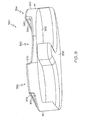
- FIGS. 8 and 9 show a patella resectioning guide 340 which is configured to receive the posterior side 48 of the patient's patella 42. Additionally, the resectioning guide 340 is configured to receive and reference a portion of a distal end of the patient's femur. As will be discussed in detail below, the surgeon may use the patella resectioning guide 340 to make a resectioning cut of the patient's patella 42.
- the resectioning guide 340 has a medial side 44 and a lateral side 46.
- the resectioning guide 340 also includes a body 350, a cutting guide 352 positioned on the lateral side 46, and an enclosed housing 354 positioned on the medial side 44.
- the cutting guide 352 and the enclosed housing 354 are secured to the body 350. Similar to the embodiments of FIGS. 5 to 7 , the body 350, cutting guide 352, and enclosed housing 354 form a single monolithic component.
- the body 350 includes a patella bone-facing surface 356 and a femoral bone-facing surface 358 opposite the patella bone-facing surface 356.
- the patella bone-facing surface 356 has a customised patient-specific negative contour 360 defined therein that is positioned between the cutting guide 352 and the housing 354.
- the negative contour 360 is configured to receive the corresponding positive contour 49 of the posterior side 48 of the patient's patella 42.
- the femoral bone-surface 358 has a customised patient-specific negative contour 362 configured to receive the corresponding positive contour 49 of the portion of the distal end of the patient's femur.
- the cutting guide 352 includes a cutting slot 370.
- the cutting slot 370 defines a resectioning plane 378 extending through the patient's patella 42 when the patella 42 is received in the customised patient-specific contour 356 of the body 350.
- the cutting slot 370 extends from an opening 374 defined in the lateral side 46 of the resectioning guide 340 to an opening (not shown) in a bone-facing surface 376 of the cutting guide 352.
- the cutting slot 370 is sized to receive a cutting saw blade (not shown).
- the enclosed housing 354 has a rear wall 380 defined on the medial side 44 of the resectioning guide 340 and a front wall 382 opposite the rear wall 380.
- An aperture 384 having a closed back (not shown) is defined in the front wall 382. The aperture 384 is sized to receive the cutting saw blade and is coplanar with the resectioning plane 378 of the cutting slot 370.
- the cutting saw blade may be inserted into the opening 374, passed through the cutting slot 370, and received in the aperture 384.
- a surgeon using the resectioning guide 340 to resect the patient's patella may place the resectioning guide 340 in contact with both the posterior side 48 of the patient's patella and the distal end of the patient's femur prior to performing the resectioning cut.
- the surgeon may place the patient's patella into the resectioning guide 340 such that the positive contour 49 of the portion of the posterior side 48 of the patient's patella is received in the corresponding negative contour 356 of the patella bone-facing surface 356.
- the surgeon may also place the femoral bone-facing surface 358 in contact with the distal end of patient's femur (not shown) such that the positive contour 49 of the portion of the distal end of the patient's femur is received in the negative contour 360 of the femoral bone-facing surface 358.
- the surgeon may then apply pressure to the anterior side of the patient's patella to secure the patella, the resectioning guide 340, and the femur together.
- the surgeon may insert a cutting saw blade into the opening 374.
- the blade passes through the cutting slot 370 and contacts the lateral side of the portion of the patient's patella received in the negative contour 356.
- the surgeon may perform a resectioning cut on the portion of the patient's patella within the negative contour 356 by moving the blade back and forth within the cutting slot 370.
- the blade is received in the aperture 384 of the housing 354. In this way, the blade is captured on both the medial side and the lateral side of the patient's patella. Additionally, bone fragments, dust, and other debris generated during the resectioning procedure are collected at the closed back of the aperture 384.
- FIG. 10 shows a resectioning guide 440 which includes a body 450 and a cutting guide 452 secured to the body 450.
- the body 450 a bone-facing surface 454 and an outer surface 458 opposite the bone-facing surface.
- the resectioning guide 440 also includes a compressible foam material 462 secured to the outer surface 458 by a suitable adhesive or other bonding mechanism. The compressible foam material 462 engages with the portion of the distal end of the patient's femur during the resectioning procedure.
- the orthopaedic surgeon may place the compressible foam material 462 in contact with the positive contour 49 of the portion of the distal end of the patient's femur.
- the surgeon may apply pressure to the anterior side of the patient's patella to secure the patella, the resectioning guide 440, and the femur together and perform the resectioning procedure as described above.
- the compressible foam material 462 may not be secured to the outer surface 458.
- the compressible foam material 462 may be placed between the resectioning guide 340 and distal end of the femur during the resectioning procedure.
Abstract
Description
- This invention relates to orthopaedic surgical instruments, especially to a patella resectioning guide.
- Joint arthroplasty is a well-known surgical procedure by which a diseased and/or damaged natural joint is replaced by a prosthetic joint. A typical knee prosthesis includes a tibial tray, a femoral component, and a polymer insert or bearing positioned between the tibial tray and the femoral component. In some cases, the knee prosthesis may also include a prosthetic patella component, which is secured to a posterior side of the patient's surgically-prepared patella. To do so, an orthopaedic surgeon may resect the posterior side of the patient's natural patella to secure the prosthetic component thereto. In use, the patella component articulates with the patient's natural or prosthetic femur during extension and flexion of the patient's knee.
- To facilitate the replacement of the natural joint with the knee prosthesis, orthopaedic surgeons use a variety of orthopaedic surgical instruments such as, for example, cutting blocks, drill guides, milling guides, and other surgical instruments. Typically, the orthopaedic surgical instruments are generic with respect to the patient such that the same orthopaedic surgical instrument may be used on a number of different patients during similar orthopaedic surgical procedures.
- In one aspect, the invention provides a patella resectioning guide, especially which is customised so that it is patient-specific. The patella resectioning guide may have a body including a bone-facing surface having a negative contour configured to receive a portion of a posterior side of a patient's patella that has a corresponding positive contour. The negative contour can be patient-specific. The patella resectioning guide may also include a cutting guide coupled to the body. The cutting guide may include a cutting slot defined therein and the cutting slot may define a resectioning plane. The cutting guide may be positioned such that the resectioning plane extends through the patient's patella when the patella is received in the negative contour of the body.
- In some embodiments, the cutting guide may be formed from a material different from the material forming the body. The cutting guide may be formed from a metallic material or a non-metallic material. In some embodiments, the body may be formed from a polymeric material. In such embodiments, the cutting guide may be over-moulded with the body. Additionally, in some embodiments, the body may have an outer surface opposite the bone-facing surface.
- The resectioning guide may further include a medial side corresponding to the medial side of the patient's patella when patella is received in the negative contour of the body. Additionally, the resectioning guide may include a lateral side corresponding to the lateral side of the patient's patella when the patella is received in the negative contour of the body. The cutting slot of the cutting guide may include a first opening on the medial side of the resectioning guide. The first opening may be sized to receive a cutting saw blade. In some embodiments, the cutting slot of the cutting guide may include a second opening on the lateral side of the resectioning guide. The second opening may also be sized to receive a cutting saw blade. Additionally, in some embodiments, the resectioning guide may include an indentation formed on the medial side of the resectioning guide. The indentation may extend from the outer surface of the body to the cutting slot of the cutting guide.
- In some embodiments, the body of the resectioning guide may include a sidewall extending upwardly from the bone-facing surface and intersecting with the resectioning plane to prevent the cutting saw blade from extending beyond the body. The sidewall may be positioned on the lateral side of the resectioning guide in some embodiments. Additionally, the cutting guide may be positioned on the medial side of the resectioning guide such that the negative contour of the body may be positioned between the cutting guide and the sidewall.
- Additionally, in some embodiments, the outer surface may have an indentation shaped to receive a clamp operable to secure the patella to the body. Additionally (or alternatively), the indentation may be sized to receive a thumb of a surgeon such that the body and patella may be held between the thumb and forefinger of the orthopaedic surgeon. Further, in some embodiments, the resectioning guide may further include compressible foam material secured to the outer surface of the body.
- In another aspect, the invention provides a resectioning guide which includes a body having a bone-facing surface including a negative contour configured to receive a portion of a posterior side of a patient's patella that has a corresponding positive contour. The negative contour can be customised so that it is patient-specific. The resectioning guide may also include a non-captured cutting guide. The non-captured cutting guide may include a cutting surface defining a resectioning plane. The cutting guide may be positioned such that the resectioning plane extends through the patient's patella when the patella is received in the negative contour of the body.
- In some embodiments, the resectioning guide may include a medial side corresponding to the medial side of the patient's patella when the portion of the posterior side of the patient's patella is received in the negative contour of the body. Additionally, the resectioning guide may include a lateral side corresponding to the lateral side of the patient's patella when the portion of the posterior side of the patient's patella is received in the negative contour of the body. The body may also include a sidewall extending upwardly from the bone-facing surface and intersecting with the resectioning plane to prevent the cutting saw blade from extending beyond the body. In some embodiments, the sidewall may be positioned on the lateral side of the resectioning guide. The cutting guide may then be positioned on the medial side of the resectioning guide such that the negative contour of the body is positioned between the cutting guide and the sidewall.
- In another aspect, the invention provides a patella resectioning guide which has a body including a first bone-facing surface having a negative contour configured to receive a portion of a posterior side of a patient's patella that has a corresponding positive contour and a second bone-facing surface opposite the first bone-facing surface. The second bone-facing surface may include a negative contour configured to receive a portion of a distal end of the patient's femur that has a corresponding positive contour. Either or each of the negative contours can be customised so that it is patient-specific. The resectioning guide may also include a cutting guide coupled to the body. The cutting guide may also include a cutting slot defined therein. The cutting slot may define a resectioning plane. The cutting guide may be positioned such that the resectioning plane extends through the patient's patella when the patella is received in the contour of the first bone-facing surface of the body.
- In some embodiments, the resectioning guide may include a medial side corresponding to the medial side of the patient's patella when the portion of the posterior side of the patient's patella is received in the negative contour of the body. Additionally, the resectioning guide may include a lateral side corresponding to the lateral side of the patient's patella when the portion of the posterior side of the patient's patella is received in the negative contour of the body. The cutting slot of the cutting guide may include an opening on the lateral side of the resectioning guide. The opening may be sized to receive a cutting saw blade.
- Additionally, in some embodiments, the resectioning guide may further include an enclosed housing extending upwardly from the bone-facing surface of the body. The enclosed housing may be spaced apart from the cutting guide. The enclosed housing may have an aperture co-planar with the resectioning plane defined by the cutting slot. Additionally, the enclosed housing may be positioned on the medial side of the resectioning guide, and the cutting guide may be positioned on the lateral side of the resectioning guide such that the negative contour is formed between the cutting guide and the enclosed housing.
- Preferably, the resectioning guide includes an enclosed housing spaced apart from the cutting guide and extending upwardly from the bone-facing surface of the body, the enclosed housing having an aperture co-planar with the resectioning plane defined by the cutting slot. Preferably, the enclosed housing is positioned on the medial side of the resectioning guide, and the cutting guide is positioned on the lateral side of the resectioning guide such that the negative contour is formed between the cutting guide and the enclosed housing.
- Embodiments of the invention are described below by way of example with reference to the accompanying drawings, in which:
-
FIG. 1 is a simplified flow diagram of a method for designing and fabricating a customised patient-specific patella resectioning guide; -
FIG. 2 is a perspective view of one embodiment of a customised patient-specific patella resectioning guide; -
FIG. 3 is another perspective view of the customised patient-specific patella resectioning guide ofFIG. 2 ; -
FIG. 4 is a perspective view the customised patient-specific patella resectioning guide ofFIG. 2 with a patient's patella positioned in the customised patient-specific patella resectioning guide; -
FIG. 5 is a perspective view of another embodiment of a customised patient-specific patella resectioning guide; -
FIG. 6 is a side elevation view of the customised patient-specific patella resectioning guide ofFIG. 5 ; -
FIG. 7 is a perspective view of another embodiment of a customised patient-specific patella resectioning guide; -
FIG. 8 is a perspective view of another embodiment of a customised patient-specific patella resectioning guide; -
FIG. 9 is another perspective view of the customised patient-specific patella resectioning guide ofFIG. 8 ; and -
FIG. 10 is a side elevation view of another embodiment of a customised patient-specific patella resectioning guide. - Terms representing anatomical references, such as anterior, posterior, medial, lateral, superior, inferior, etcetera, may be used throughout the specification in reference to the orthopaedic implants and surgical instruments described herein as well as in reference to the patient's natural anatomy. Such terms have well-understood meanings in both the study of anatomy and the field of orthopaedics. Use of such anatomical reference terms in the written description and claims is intended to be consistent with their well-understood meanings unless noted otherwise.
- Referring to the drawings,
FIG. 1 is a flow diagram with details of amethod 10 which can be used to fabricate a customised patient-specific orthopaedic surgical instrument. The term "customised patient-specific orthopaedic surgical instrument" is used in this document to refer to a surgical tool for use by a surgeon in performing an orthopaedic surgical procedure that is intended, and configured, for use on a particular patient. A "customised patient-specific orthopaedic surgical instrument" is distinct from a standard, non-patient specific orthopaedic surgical instrument which is intended for use on a variety of different patients. Additionally, it should be appreciated that the term "customised patient-specific orthopaedic surgical instrument" is distinct from orthopaedic prostheses, whether patient-specific or generic, which are surgically implanted in the body of the patient. Rather, customised patient-specific orthopaedic surgical instruments are used by an orthopaedic surgeon to assist in the implantation of orthopaedic prostheses. - In some embodiments, the customised patient-specific orthopaedic surgical instrument may be customised to the particular patient based on the location at which the instrument is to be coupled to one or more bones of the patient. For example, in some embodiments, the customised patient-specific orthopaedic instrument may be a customised patient-specific patella resectioning guide including one or more bone-contacting or facing surfaces having a negative contour that matches the contour of a portion of the patient's patella, which is discussed in more detail below with reference to
FIGS. 2 to 10 . As such, the customised patient-specific patella resectioning guide is configured to be coupled to the patient's patella at a unique location and position with respect to the patient's bony anatomy. That is, the negative contours of the bone-contacting surfaces are configured to receive a matching contour surface of the portion of the patient's patella (and, in some cases, femur). As such, the orthopaedic surgeon's guesswork and/or intra-operative decision-making with respect to the placement of the patient-specific patella resectioning guide are reduced. The orthopaedic surgeon may simply couple the customised patient-specific patella resectioning guide to the patient's patella. When so coupled, the customised patient-specific patella resectioning guide defines the thickness of bone the surgeon will resect from the posterior side of the patient's patella. - As shown in
FIG. 1 , themethod 10 includes process steps 12, 14 in which an orthopaedic surgeon performs pre-operative planning of the patella resectioning procedure to be performed on a patient. The process steps 12, 14 may be performed in any order or contemporaneously with each other. Inprocess step 12, a number of medical images of the patient's patella and the surrounding bony anatomy are generated. To do so, the orthopaedic surgeon or other healthcare provider may operate an imaging system to generate the medical images. The medical images may be embodied as any number and type of medical images capable of being used to generate a three-dimensional rendered model of the patient's patella and surrounding bony anatomy. For example, the medical images may be embodied as any number of computed tomography (CT) images, magnetic resonance imaging (MRI) images, or other three-dimensional medical images. Additionally, or alternatively, as discussed in more detail below in regard to processstep 18, the medical images may be embodied as a number of X-ray images or other two-dimensional images from which a three-dimensional rendered model of the patient's patella and the surrounding bony anatomy may be generated. - In
process step 14, the orthopaedic surgeon may determine any additional pre-operative constraint data. The constraint data may be based on the orthopaedic surgeon's preferences, preferences of the patient, anatomical aspects of the patient, guidelines established by the healthcare facility, or the like. For example, the constraint data may include the orthopaedic surgeon's preference for a particular prosthesis type, the thickness of the bone to resect, the size range of the orthopaedic implant, and/or the like. In some embodiments, the orthopaedic surgeon's preferences are saved as a surgeon's profile, which may be used as a default constraint values for further surgical plans. - In
process step 16, the medical images and the constraint data, if any, are transmitted or otherwise provided to an orthopaedic surgical instrument vendor or manufacturer. The medical images and the constraint data may be transmitted to the vendor via electronic means such as a network or the like. After the vendor has received the medical images and the constraint data, the vendor processes the images instep 18. The orthopaedic surgical instrument vendor or manufacturer process the medical images to facilitate the determination of the proper positioning of the prosthetic component, implant sizing, and fabrication of the customised patient-specific patella resectioning guide as discussed in more detail below. - In
process step 20, the vendor may convert or otherwise generate three-dimensional images from the medical images. For example, in embodiments wherein the medical images are embodied as a number of two-dimensional images, the vendor may use a suitable computer algorithm to generate one or more three-dimensional images from the number of two-dimensional images. Additionally, in some embodiments, the medical images may be generated based on an established standard such as the Digital Imaging and Communications in Medicine (DICOM) standard. In such embodiments, an edge-detection, thresholding, watershed, or shape-matching algorithm may be used to convert or reconstruct images to a format acceptable in a computer aided design application or other image processing application. Further, in some embodiments, an algorithm may be used to account for tissue such as cartilage not discernable in the generated medical images. In such embodiments, any three-dimensional model of the patient-specific instrument (see, e.g.,process step 26 below) may be modified according to such algorithm to increase the fit and function of the instrument. - In
process step 22, the vendor may process the medical images, and/or the converted/reconstructed images fromprocess step 20, to determine a number of aspects related to the bony anatomy of the patient such as the anatomical axis of the patient's bones, the mechanical axis of the patient's bone, other axes and various landmarks, and/or other aspects of the patient's bony anatomy. To do so, the vendor may use any suitable algorithm to process the images. - The resectioning plane of the patient's patella is determined in
process step 24. The planned resectioning plane is determined based on the type, size, and position of the prosthetic patella component to be used during the orthopaedic procedure, on the process images such as specific landmarks identified in the images, and on the constraint data supplied by the orthopaedic surgeon in previous process steps 14, 16. The type and/or size of the prosthetic patella component may be determined based on the patient's anatomy and the constraint data. For example, the constraint data may dictate the type, make, model, size, or other characteristic of the prosthetic patella component. The selection of the prosthetic patella component may also be modified based on the medical images such that a prosthetic component usable with the bony anatomy of the patient and matching the constraint data or preferences of the orthopaedic surgeon is selected. - In addition to the type and size of the prosthetic patella component, the planned location and position of the prosthetic patella component relative to the patient's bony anatomy is determined. To do so, a digital template of the prosthetic patella component may be overlaid onto one or more of the processed medical images. The vendor may use any suitable algorithm to determine a recommended location and orientation of the prosthetic patella component (i.e., the digital template) with respect to the patient's bone based on the processed medical images (e.g., landmarks of the patient's patella and/or femur defined in the images) and/or the constraint data. Additionally, any one or more other aspects of the patient's bony anatomy may be used to determine the proper positioning of the digital template. In some embodiments, the digital template along with surgical alignment parameters may be presented to the orthopaedic surgeon for approval.
- The planned resectioning planes for the patient's patella may then be determined based on the determined size, location, and orientation of the prosthetic patella component. In addition, other aspects of the patient's bony anatomy, as determined in
process step 22, may be used to determine or adjust the planned resectioning planes. For example, the determined mechanical axis, landmarks, and/or other determined aspects of the femur and/or patella of the patient may be used to determine the planned resectioning planes. - In
process step 26, a model of the customised patient-specific patella resectioning guide is generated. In some embodiments, the model is embodied as a three-dimensional rendering of the customised patient-specific patella resectioning guide. In other embodiments, the model may be embodied as a mock-up or fast prototype of the customised patient-specific patella resectioning guide. The customised patient-specific patella resectioning guide to be modelled and fabricated may be determined based on the patella orthopaedic surgical procedure to be performed, the constraint data, and/or the type of prosthetic patella component to be implanted in the patient. - The particular shape of the customised patient-specific patella resectioning guide is determined based on the planned location of the patella resectioning guide relative to the patient's bony anatomy. The location of the customised patient-specific patella resectioning guide with respect to the patient's bony anatomy is determined based on the type and determined location of the prosthetic patella component to be used during the orthopaedic surgical procedure. That is, the planned location of the customised patient-specific patella resectioning guide relative to the patient's bony anatomy may be selected based on, in part, the planned resectioning planes of the patient's bone(s) as determined in
step 24. For example, the location of the patella resectioning guide is selected such that the cutting guide of the patella resectioning guide matches one or more of the planned resectioning planes determined inprocess step 24. Additionally, the planned location of the patella resectioning guide may be based on the identified landmarks of the patient's patella and femur identified inprocess step 22. - In some embodiments, the particular shape or configuration of the customised patient-specific patella resectioning guide may be determined based on the planned location of the guide relative to the patient's bony anatomy. That is, the customised patient-specific patella resectioning guide may include a bone-contacting surface having a negative contour that matches a corresponding positive contour of a portion of the patella of the patient. The positive contour of the portion of the patella of the patient may be received in the negative contour of the patella resectioning guide such that the patella is placed in a unique location. When the patella resectioning guide receives the patient's patella, one or more guides (e.g., cutting guide) of the patella resectioning guide may be aligned to the one or more of the resectioning plane(s), as discussed above.
- After the model of the customised patient-specific patella resectioning guide has been generated in
process step 26, the model is validated inprocess step 28. The model may be validated by, for example, analysing the rendered model while the three-dimensional model of the patient's patella is received in the resectioning guide model to verify the correlation of the cutting guide and the resectioning plane. Additionally, the model may be validated by transmitting or otherwise providing the model generated instep 26 to the orthopaedic surgeon for review. For example, in embodiments wherein the model is a three-dimensional rendered model, the model along with the three-dimensional images of the patient's relevant bone(s) may be transmitted to the surgeon for review. In embodiments wherein the model is a physical prototype, the model may be shipped to the orthopaedic surgeon for validation. - After the model has been validated in
process step 28, the customised patient-specific patella resectioning guide is fabricated inprocess step 30. The customised patient-specific patella resectioning guide may be fabricated using any suitable fabrication device and method. Additionally, the customised patient-specific patella resectioning guide may be formed from any suitable material such as a metallic material, a plastic material, or combination thereof depending on, as discussed in more detail below. The fabricated customised patient-specific patella resectioning guide is subsequently shipped or otherwise provided to the orthopaedic surgeon. The surgeon performs the orthopaedic surgical procedure inprocess step 32 using the customised patient-specific patella resectioning guide. As discussed above, because the orthopaedic surgeon does not need to determine the proper location of the patella resectioning guide intra-operatively, which typically requires some amount of estimation on part of the surgeon, the guesswork and/or intra-operative decision-making on part of the orthopaedic surgeon is reduced. - It should also be appreciated that variations in the bony anatomy of the patient may require more than one customised patient-specific patella resectioning guide to be fabricated according to the method described herein. For example, the patient may require the implantation of two prosthetic patella components to replace both natural knees. As such, the surgeon may follow the
method 10 ofFIG. 1 to fabricate a different customised patient-specific patella resectioning guide for use in replacing each natural knee. Each customised patient-specific patella resectioning guide defines a particular resectioning plane relative to each particular patella that is different due to the variation in the bony anatomy of each knee joint. -
FIGS. 2 to 4 show an embodiment of a customised patient-specificpatella resectioning guide 40 which is configured to receive a portion of a posterior side 48 of a patient's patella 42 (seeFIG. 4 ). Theresectioning guide 40 has amedial side 44 and alateral side 46. Themedial side 44 corresponds to the medial side of the patient'spatella 42 when thepatella 42 is received in theresectioning guide 40. Similarly, thelateral side 46 corresponds to the lateral side of the patient'spatella 42 when thepatella 42 is received in theresectioning guide 40. The orthopaedic surgeon may use thepatella resectioning guide 40 to make a resectioning cut of the patient'spatella 42. A prosthetic patella component may be subsequently secured to the resected surface of the posterior side 48 of the patient'spatella 42. - As shown in
FIGS. 2 and3 , thepatella resectioning guide 40 includes abody 50 and a captured cuttingguide 52, which is secured to thebody 50. Thebody 50 is formed from a polymeric material such as polyethylene or ultra-high molecular weight polypropylene (UHMWPP), and the cuttingguide 52 is formed from an implant grade metallic material such as steel, titanium, or cobalt chromium. However, in other embodiments, the cuttingguide 52 may also be formed from a polymeric material. That is, thebody 50 and the cuttingguide 52 may be formed from a single monolithic component. As such, thebody 50 and the cuttingguide 52 may be made of the same or different materials. - In the embodiment of
FIGS. 2 to 4 , thebody 50 includes a bone-facingsurface 54 and anouter surface 58 opposite the bone-facingsurface 54. The bone-facingsurface 54 extends from themedial side 44 of theresectioning guide 40 to thelateral side 46. The bone-facingsurface 54 includes a customised patient-specificnegative contour 56 defined therein. Thenegative contour 56 is configured to receive a correspondingpositive contour 49 of the posterior side 48 of the patient'spatella 42. As discussed above, thenegative contour 56 of the bone-facingsurface 54 allows the surgeon to position the patient'spatella 42 in theresectioning guide 40 in a unique, pre-determined location and orientation. - As shown in
FIG. 3 , theouter surface 58 includes arecess 59 shaped to receive an end of a clamp (not shown) or other tool for holding the patient's patella in theresectioning guide 40. As shown inFIG. 3 , therecess 59 has around indentation 60 and a pair ofslots 62 formed in theouter surface 58. Theround indentation 60 and theslots 62 are sized to receive the clamp holding thepatella 42 to thebody 50. It should be appreciated that in other embodiments therecess 59 may include anindentation 60 formed as square, triangular, or any other form suitable to receive the clamp. Similarly, it should be appreciated that therecess 59 may include additional slots of differing sizes as necessary to receive the clamp. Additionally, in some embodiments, the surgeon may secure thepatella 42 to thebody 50 by fixing thepatella 42 andbody 50 between two fingers. In such embodiments, therecess 59 is sized to receive one of the surgeon's fingers therein and may or may not be configured to receive the end of the clamp. For example, in such embodiments, therecess 59 may not include theslots 62. - The cutting
guide 52 includes a cuttingslot 70 extending from themedial side 44 of theresectioning guide 40 to thelateral side 46 of theresectioning guide 40. The cuttingslot 70 defines aresectioning plane 72 that extends through the patient'spatella 42 when thepatella 42 is received in the customised patient-specific contour 56 of thebody 50. The cuttingslot 70 extends from amedial opening 74 formed in themedial side 44 through an opening (not shown) into thenegative contour 56 of thebody 50. The cuttingslot 70 also extends from alateral opening 76 formed in thelateral side 46 through anopening 82 into thenegative contour 56 of thebody 50. The cuttingslot 70 is sized to receive a cutting saw blade (not shown). - A
viewing window 90 is formed on themedial side 44 of theresectioning guide 40. Theviewing window 90 is formed as anindentation 92 extending from theouter surface 58 of thebody 50 to the interior of the cuttingslot 70 of the cuttingguide 52. Theviewing window 90 is positioned to allow the surgeon to view the cutting saw blade within the cuttingslot 70. It should be appreciated that in other embodiments thebody 50 and cuttingguide 52 may include additional viewing windows of different sizes and shapes to facilitate the surgeon's view of the cutting saw blade. For example, in one embodiment, theresectioning guide 40 may include a viewing window on each of the medial andlateral sides - As shown in
FIG. 4 , in one embodiment, thepatella 42 remains secured to thetendons 100 of the patient during the resectioning procedure. Thetendons 100 may contact the bone-facingsurface 54 of thebody 50 when thepositive contour 49 of the posterior side 48 of the patient'spatella 42 is received in thenegative contour 56. As such, in some embodiments, thebody 50 may include indentations in thebone facing surface 54 to provide space to receive a portion of thetendons 100. - In use, an orthopaedic surgeon may secure the
patella 42 to thebody 50 using the clamp or other securing means. The surgeon may then insert the cutting saw blade into theopening 76. The blade passes through the cuttingslot 70 and contacts the medial side of the portion of thepatella 42 received in thenegative contour 56. Following theresectioning plane 72 defined by the cuttingslot 70, the surgeon may perform the resectioning cut on the patient'spatella 42 by moving the saw blade back and forth within cuttingslot 70. As the blade cuts through thepatella 42, the blade is received in theopening 82 of the cuttingslot 70. In this way, the blade is captured on both the medial side and the lateral side of the patient'spatella 42. -
FIGS. 5 and6 show another embodiment ofpatella resectioning guide 140. Similar to the embodiment ofFIGS. 2 to 4 , theresectioning guide 140 has amedial side 44 and alateral side 46. Theresectioning guide 140 also includes abody 150 and a cuttingguide 152, which is secured to thebody 150 and positioned on themedial side 44 of theresectioning guide 140. Theresectioning guide 140 is formed as a single monolithic component from a polymeric material such as those discussed above with reference to the embodiment ofFIGS. 2 to 4 . - The
body 150 includes a bone-facingsurface 154 having a customised patient-specificnegative contour 156 defined therein. Similar to thenegative contour 56, thenegative contour 156 is configured to receive the correspondingpositive contour 49 of the posterior side 48 of the patient'spatella 42. Thebody 150 also includes asidewall 158 extending upwardly from the bone-facingsurface 154. Thesidewall 158 is positioned on thelateral side 46 of theresectioning guide 140 such that the customised patient-specific contour 156 is positioned between thesidewall 158 and the cuttingguide 152. - Similar to the embodiment of
FIGS. 2 to 4 , thebody 150 also includes anouter surface 160 opposite the bone-facingsurface 154. Theouter surface 160 includes arecess 162 shaped to receive an end of a clamp (not shown) or other tool for holding the patient'spatella 42 in theresectioning guide 140. Therecess 162 has around indentation 164 and a pair ofslots 166 formed in theouter surface 160. Theround indentation 164 and theslots 166 are sized to receive the clamp (not shown) operable to secure thepatella 42 to thebody 150. It should be appreciated that therecess 162 may include any indentations, slots, or the like necessary to hold the patient'spatella 42 in theresectioning guide 140. - The cutting
guide 152 includes acutting slot 170 sized to receive a cutting saw blade (not shown). The cuttingslot 170 extends from anopening 174 defined in themedial side 44 of theresectioning guide 140 to an opening (not shown) in a bone-facingsurface 176 of the cuttingguide 152. The cuttingslot 170 defines aresectioning plane 178 extending through the patient'spatella 42 when thepatella 42 is received in the customised patient-specificnegative contour 156 of thebody 150. Thesidewall 158 intersects with theresectioning plane 178 and extends upwardly from the body 150 a length sufficient to prevent a cutting saw blade (not shown) from extending beyond thelateral side 46 of theresectioning guide 140 during use. - Similar to the embodiment of
FIGS. 2 to 4 , thetendons 100 of the patient may contact the bone-facingsurface 154 of thebody 150 when thepositive contour 49 of the posterior side 48 of the patient'spatella 42 is received in thenegative contour 156. To provide additional space for thetendons 100, the bone-facingsurface 154 has a medial-to-lateral concave contour (seeFIG. 6 ) which is configured to receive a portion oftendons 100. - In use, an orthopaedic surgeon may secure the
patella 42 to thebody 150 using the clamp or other securing means. The surgeon may then insert the cutting saw blade into theopening 174. The blade passes through thecutting slot 170 and contacts the medial side of the portion of thepatella 42 received in thenegative contour 156. Following theresectioning plane 178 defined by the cuttingslot 170, the surgeon may perform a resectioning cut on the patient'spatella 42 by moving the blade back and forth within the cuttingslot 170. In this way, the blade is captured within the cuttingguide 152 while the surgeon performs the resectioning cut. As the blade cuts through thepatella 42, thesidewall 158 prevents the surgeon from pushing the blade beyond theresectioning guide 140. - Referring now to
FIG. 7 , in another embodiment, the customised patient-specific patella resectioning guide may be embodied as apatella resectioning guide 240. Similar to the embodiments ofFIGS. 2 to 6 , theresectioning guide 240 has amedial side 44 and alateral side 46. Theresectioning guide 240 also includes abody 250 and anon-captured cutting guide 252 that is secured to thebody 250 and formed on themedial side 44. Like the embodiment ofFIGS. 5 and6 , thepatella resectioning guide 240 is formed as a single monolithic component. - The
body 250 includes a bone-facingsurface 254 having a customised patient-specificnegative contour 256 defined therein. Thenegative contour 256 is configured to receive the correspondingpositive contour 49 of the posterior side 48 of the patient'spatella 42. Similar to theresectioning guide 140 ofFIGS. 5 and6 , thebody 250 also includes asidewall 258 extending upwardly from the bone-facingsurface 254. Thesidewall 258 is positioned on thelateral side 46 of theresectioning guide 240 such that the customised patient-specificnegative contour 256 is positioned between the cuttingguide 252 and thesidewall 258. - Similar to the embodiment of
FIGS. 2 to 6 , thebody 250 also includes anouter surface 260 opposite the bone-facingsurface 254. Theouter surface 260 includes arecess 262 shaped to receive an end of a clamp (not shown) or other tool for holding the patient's patella in theresectioning guide 240. It should be appreciated that therecess 262 may include any indentations, slots, or the like necessary to hold the patient'spatella 42 in theresectioning guide 240. - The
non-captured cutting guide 252 includes a cuttingsurface 270 and the bone-facingsurface 254. The cuttingsurface 270 extends from themedial side 44 to the bone-facingsurface 254 of thebody 250. That is, the cuttingsurface 270 and the bone-facingsurface 254 are co-planar with each other. The cuttingsurface 270 defines aresectioning plane 272 that the surgeon follows to perform a resectioning cut on the patient'spatella 42 when thepatella 42 is received in the customised patient-specificnegative contour 256 of thebody 250. Thesidewall 258 intersects with theresectioning plane 272 and extends upwardly from the body 150 a length sufficient to prevent a cutting saw blade (not shown) from extending beyond thelateral side 46 of theresectioning guide 240 during use. -
FIGS. 8 and9 show apatella resectioning guide 340 which is configured to receive the posterior side 48 of the patient'spatella 42. Additionally, theresectioning guide 340 is configured to receive and reference a portion of a distal end of the patient's femur. As will be discussed in detail below, the surgeon may use thepatella resectioning guide 340 to make a resectioning cut of the patient'spatella 42. - Similar to the previous embodiments, the
resectioning guide 340 has amedial side 44 and alateral side 46. Theresectioning guide 340 also includes abody 350, a cuttingguide 352 positioned on thelateral side 46, and anenclosed housing 354 positioned on themedial side 44. The cuttingguide 352 and theenclosed housing 354 are secured to thebody 350. Similar to the embodiments ofFIGS. 5 to 7 , thebody 350, cuttingguide 352, andenclosed housing 354 form a single monolithic component. - In the embodiment shown in
FIG. 8 , thebody 350 includes a patella bone-facingsurface 356 and a femoral bone-facingsurface 358 opposite the patella bone-facingsurface 356. The patella bone-facingsurface 356 has a customised patient-specificnegative contour 360 defined therein that is positioned between the cuttingguide 352 and thehousing 354. Thenegative contour 360 is configured to receive the correspondingpositive contour 49 of the posterior side 48 of the patient'spatella 42. The femoral bone-surface 358 has a customised patient-specificnegative contour 362 configured to receive the correspondingpositive contour 49 of the portion of the distal end of the patient's femur. - The cutting
guide 352 includes acutting slot 370. The cuttingslot 370 defines aresectioning plane 378 extending through the patient'spatella 42 when thepatella 42 is received in the customised patient-specific contour 356 of thebody 350. The cuttingslot 370 extends from anopening 374 defined in thelateral side 46 of theresectioning guide 340 to an opening (not shown) in a bone-facingsurface 376 of the cuttingguide 352. The cuttingslot 370 is sized to receive a cutting saw blade (not shown). - The
enclosed housing 354 has arear wall 380 defined on themedial side 44 of theresectioning guide 340 and afront wall 382 opposite therear wall 380. Anaperture 384 having a closed back (not shown) is defined in thefront wall 382. Theaperture 384 is sized to receive the cutting saw blade and is coplanar with theresectioning plane 378 of thecutting slot 370. - In use, the cutting saw blade may be inserted into the
opening 374, passed through thecutting slot 370, and received in theaperture 384. A surgeon using theresectioning guide 340 to resect the patient's patella may place theresectioning guide 340 in contact with both the posterior side 48 of the patient's patella and the distal end of the patient's femur prior to performing the resectioning cut. The surgeon may place the patient's patella into theresectioning guide 340 such that thepositive contour 49 of the portion of the posterior side 48 of the patient's patella is received in the correspondingnegative contour 356 of the patella bone-facingsurface 356. The surgeon may also place the femoral bone-facingsurface 358 in contact with the distal end of patient's femur (not shown) such that thepositive contour 49 of the portion of the distal end of the patient's femur is received in thenegative contour 360 of the femoral bone-facingsurface 358. The surgeon may then apply pressure to the anterior side of the patient's patella to secure the patella, theresectioning guide 340, and the femur together. - The surgeon may insert a cutting saw blade into the
opening 374. The blade passes through thecutting slot 370 and contacts the lateral side of the portion of the patient's patella received in thenegative contour 356. Following theresectioning plane 378 defined by the cuttingslot 370, the surgeon may perform a resectioning cut on the portion of the patient's patella within thenegative contour 356 by moving the blade back and forth within the cuttingslot 370. As the blade cuts through thepatella 42, the blade is received in theaperture 384 of thehousing 354. In this way, the blade is captured on both the medial side and the lateral side of the patient's patella. Additionally, bone fragments, dust, and other debris generated during the resectioning procedure are collected at the closed back of theaperture 384. -
FIG. 10 shows aresectioning guide 440 which includes abody 450 and a cuttingguide 452 secured to thebody 450. The body 450 a bone-facingsurface 454 and anouter surface 458 opposite the bone-facing surface. Theresectioning guide 440 also includes acompressible foam material 462 secured to theouter surface 458 by a suitable adhesive or other bonding mechanism. Thecompressible foam material 462 engages with the portion of the distal end of the patient's femur during the resectioning procedure. - In use, the orthopaedic surgeon may place the
compressible foam material 462 in contact with thepositive contour 49 of the portion of the distal end of the patient's femur. When the patella is secured to theresectioning guide 440, the surgeon may apply pressure to the anterior side of the patient's patella to secure the patella, theresectioning guide 440, and the femur together and perform the resectioning procedure as described above. It should be appreciated that in other embodiments thecompressible foam material 462 may not be secured to theouter surface 458. In such embodiments, thecompressible foam material 462 may be placed between theresectioning guide 340 and distal end of the femur during the resectioning procedure.
Claims (15)
- A patella resectioning guide which comprises (i) a body including a bone-facing surface having a negative contour configured to receive a portion of a posterior side of a patient's patella that has a corresponding positive contour and (ii) a cutting guide coupled to the body, the cutting guide including a cutting slot defined therein, in which (i) the cutting slot defines a resectioning plane, and (ii) the cutting guide is positioned such that the resectioning plane extends through the patient's patella when the patella is received in the negative contour of the body.
- A guide as claimed in claim 1, in which the body is formed of a polymeric material, and the cutting guide is over-moulded with the body of the patella resectioning guide.
- A guide as claimed in claim 1, in which the body has an outer surface opposite the bone-facing surface, the outer surface having an indentation shaped to receive a clamp configured to secure the patella to the body.
- A guide as claimed in claim 1, which has:a medial side corresponding to the medial side of the patient's patella when patella is received in the negative contour of the body, anda lateral side corresponding to the lateral side of the patient's patella when the patella is received in the negative contour of the body,in which the cutting slot of the cutting guide includes a first opening on the medial side of the resectioning guide, the first opening being sized to receive a cutting saw blade.
- A guide as claimed in claim 4, in which the cutting slot of the cutting guide includes a second opening on the lateral side of the resectioning guide, the second opening being sized to receive a cutting saw blade.
- A guide as claimed in claim 4, which has an indentation formed on the medial side of the resectioning guide, and in which the body has an outer surface opposite the bone-facing surface, the indentation extending from the outer surface of the body to the cutting slot of the cutting guide.
- A guide as claimed in claim 4, in which the body includes a sidewall extending upwardly from the bone-facing surface and intersecting with the resectioning plane to prevent the cutting saw blade from extending beyond the body.
- A guide as claimed in claim 7, in which:the sidewall is positioned on the lateral side of the resectioning guide, andthe cutting guide is positioned on the medial side of the resectioning guide such that the negative contour of the body is positioned between the cutting guide and the sidewall.
- A guide as claimed in claim 1, in which:the body of the resectioning guide has an outer surface opposite the bone-facing surface, andthe outer surface has an indentation sized to receive a thumb of an orthopaedic surgeon such that the body and patella may be held between the thumb and forefinger of the surgeon.
- A guide as claimed in claim 1, which includes a compressible foam material secured to an outer surface of the body, the outer surface being opposite the bone-facing surface of the body.
- A resectioning guide which comprises (i) a body having a bone-facing surface including a negative contour configured to receive a portion of a posterior side of a patient's patella that has a corresponding positive contour and (ii) a non-captured cutting guide including a cutting surface, in which (i) the cutting surface defines a resectioning plane, and (ii) the cutting guide is positioned such that the resectioning plane extends through the patient's patella when the patella is received in the negative contour of the body.
- A guide as claimed in claim 11, which has:a medial side corresponding to the medial side of the patient's patella when the portion of the posterior side of the patient's patella is received in the negative contour of the body, anda lateral side corresponding to the lateral side of the patient's patella when the portion of the posterior side of the patient's patella is received in the negative contour of the body,in which the body further includes a sidewall extending upwardly from the bone-facing surface and intersecting with the resectioning plane to prevent the cutting saw blade from extending beyond the body.
- A guide as claimed in claim 12, in which:the sidewall is positioned on the lateral side of the resectioning guide, andthe cutting guide is positioned on the medial side of the resectioning guide such that the negative contour of the body is positioned between the cutting guide and the sidewall.
- A patella resectioning guide which comprises:a body including (i) a first bone-facing surface having a negative contour configured to receive a portion of a posterior side of a patient's patella that has a corresponding positive contour and (ii) a second bone-facing surface opposite the first bone-facing surface, the second bone-facing surface having a negative contour configured to receive a portion of a distal end of the patient's femur that has a corresponding positive contour, anda cutting guide coupled to the body, the cutting guide including a cutting slot defined therein,in which (i) the cutting slot defines a resectioning plane, and (ii) the cutting guide is positioned such that the resectioning plane extends through the patient's patella when the patella is received in the contour of the first bone-facing surface of the body.
- A guide as claimed in claim 14, which has:a medial side corresponding to the medial side of the patient's patella when the portion of the posterior side of the patient's patella is received in the negative contour of the body anda lateral side corresponding to the lateral side of the patient's patella when the portion of the posterior side of the patient's patella is received in the negative contour of the body.in which (i) the cutting slot of the cutting guide includes an opening on the lateral side of the resectioning guide, and (ii) the opening is sized to receive a cutting saw blade.
Priority Applications (2)
| Application Number | Priority Date | Filing Date | Title |
|---|---|---|---|
| EP11184387.6A EP2404560B1 (en) | 2009-01-16 | 2010-01-12 | Patella resectioning guide |
| EP15150198.8A EP2862525B1 (en) | 2009-01-16 | 2010-01-12 | Patella resectioning guide |
Applications Claiming Priority (1)
| Application Number | Priority Date | Filing Date | Title |
|---|---|---|---|
| US12/355,235 US20100185202A1 (en) | 2009-01-16 | 2009-01-16 | Customized patient-specific patella resectioning guide |
Related Child Applications (3)
| Application Number | Title | Priority Date | Filing Date |
|---|---|---|---|
| EP11184387.6A Division EP2404560B1 (en) | 2009-01-16 | 2010-01-12 | Patella resectioning guide |
| EP15150198.8A Division EP2862525B1 (en) | 2009-01-16 | 2010-01-12 | Patella resectioning guide |
| EP11184387.6 Division-Into | 2011-10-07 |
Publications (2)
| Publication Number | Publication Date |
|---|---|
| EP2208470A1 true EP2208470A1 (en) | 2010-07-21 |
| EP2208470B1 EP2208470B1 (en) | 2012-02-29 |
Family
ID=42102981
Family Applications (3)
| Application Number | Title | Priority Date | Filing Date |
|---|---|---|---|
| EP15150198.8A Active EP2862525B1 (en) | 2009-01-16 | 2010-01-12 | Patella resectioning guide |
| EP10150487A Active EP2208470B1 (en) | 2009-01-16 | 2010-01-12 | Patella resectioning guide |
| EP11184387.6A Active EP2404560B1 (en) | 2009-01-16 | 2010-01-12 | Patella resectioning guide |
Family Applications Before (1)
| Application Number | Title | Priority Date | Filing Date |
|---|---|---|---|
| EP15150198.8A Active EP2862525B1 (en) | 2009-01-16 | 2010-01-12 | Patella resectioning guide |
Family Applications After (1)
| Application Number | Title | Priority Date | Filing Date |
|---|---|---|---|
| EP11184387.6A Active EP2404560B1 (en) | 2009-01-16 | 2010-01-12 | Patella resectioning guide |
Country Status (9)
| Country | Link |
|---|---|
| US (1) | US20100185202A1 (en) |
| EP (3) | EP2862525B1 (en) |
| JP (1) | JP5570826B2 (en) |
| CN (1) | CN101797175B (en) |
| AT (1) | ATE547054T1 (en) |
| AU (1) | AU2010200130B2 (en) |
| DK (1) | DK2208470T3 (en) |
| ES (1) | ES2379592T3 (en) |
| ZA (1) | ZA201000324B (en) |
Cited By (5)
| Publication number | Priority date | Publication date | Assignee | Title |
|---|---|---|---|---|
| WO2012154914A1 (en) * | 2011-05-11 | 2012-11-15 | The Cleveland Clinic Foundation | Generating patient specific instruments for use as surgical aids |
| WO2013060842A1 (en) * | 2011-10-28 | 2013-05-02 | Materialise N.V. | Guides with pressure points |
| WO2013165559A1 (en) * | 2012-05-03 | 2013-11-07 | DePuy Synthes Products, LLC | Surgical guide with cut resistant inserts |
| WO2016062973A1 (en) * | 2014-10-24 | 2016-04-28 | Aston Medical | Device for preparing a patella for placement of a patellar implant |
| US9411939B2 (en) | 2012-09-12 | 2016-08-09 | DePuy Synthes Products, Inc. | Method for producing patient-specific plate |
Families Citing this family (133)
| Publication number | Priority date | Publication date | Assignee | Title |
|---|---|---|---|---|
| US10278711B2 (en) | 2006-02-27 | 2019-05-07 | Biomet Manufacturing, Llc | Patient-specific femoral guide |
| US9289253B2 (en) | 2006-02-27 | 2016-03-22 | Biomet Manufacturing, Llc | Patient-specific shoulder guide |
| US8407067B2 (en) | 2007-04-17 | 2013-03-26 | Biomet Manufacturing Corp. | Method and apparatus for manufacturing an implant |
| US9339278B2 (en) | 2006-02-27 | 2016-05-17 | Biomet Manufacturing, Llc | Patient-specific acetabular guides and associated instruments |
| US8377066B2 (en) | 2006-02-27 | 2013-02-19 | Biomet Manufacturing Corp. | Patient-specific elbow guides and associated methods |
| US9918740B2 (en) | 2006-02-27 | 2018-03-20 | Biomet Manufacturing, Llc | Backup surgical instrument system and method |
| US8568487B2 (en) | 2006-02-27 | 2013-10-29 | Biomet Manufacturing, Llc | Patient-specific hip joint devices |
| US8858561B2 (en) | 2006-06-09 | 2014-10-14 | Blomet Manufacturing, LLC | Patient-specific alignment guide |
| US9173661B2 (en) | 2006-02-27 | 2015-11-03 | Biomet Manufacturing, Llc | Patient specific alignment guide with cutting surface and laser indicator |
| US7967868B2 (en) | 2007-04-17 | 2011-06-28 | Biomet Manufacturing Corp. | Patient-modified implant and associated method |
| US8535387B2 (en) | 2006-02-27 | 2013-09-17 | Biomet Manufacturing, Llc | Patient-specific tools and implants |
| US8864769B2 (en) | 2006-02-27 | 2014-10-21 | Biomet Manufacturing, Llc | Alignment guides with patient-specific anchoring elements |
| US8608748B2 (en) | 2006-02-27 | 2013-12-17 | Biomet Manufacturing, Llc | Patient specific guides |
| US9113971B2 (en) | 2006-02-27 | 2015-08-25 | Biomet Manufacturing, Llc | Femoral acetabular impingement guide |
| US8473305B2 (en) | 2007-04-17 | 2013-06-25 | Biomet Manufacturing Corp. | Method and apparatus for manufacturing an implant |
| US8282646B2 (en) | 2006-02-27 | 2012-10-09 | Biomet Manufacturing Corp. | Patient specific knee alignment guide and associated method |
| US8092465B2 (en) | 2006-06-09 | 2012-01-10 | Biomet Manufacturing Corp. | Patient specific knee alignment guide and associated method |
| US8241293B2 (en) | 2006-02-27 | 2012-08-14 | Biomet Manufacturing Corp. | Patient specific high tibia osteotomy |
| US8603180B2 (en) | 2006-02-27 | 2013-12-10 | Biomet Manufacturing, Llc | Patient-specific acetabular alignment guides |
| US8070752B2 (en) | 2006-02-27 | 2011-12-06 | Biomet Manufacturing Corp. | Patient specific alignment guide and inter-operative adjustment |
| US20150335438A1 (en) | 2006-02-27 | 2015-11-26 | Biomet Manufacturing, Llc. | Patient-specific augments |
| US8608749B2 (en) | 2006-02-27 | 2013-12-17 | Biomet Manufacturing, Llc | Patient-specific acetabular guides and associated instruments |
| US8591516B2 (en) | 2006-02-27 | 2013-11-26 | Biomet Manufacturing, Llc | Patient-specific orthopedic instruments |
| US9345548B2 (en) | 2006-02-27 | 2016-05-24 | Biomet Manufacturing, Llc | Patient-specific pre-operative planning |
| US8298237B2 (en) | 2006-06-09 | 2012-10-30 | Biomet Manufacturing Corp. | Patient-specific alignment guide for multiple incisions |
| US9907659B2 (en) | 2007-04-17 | 2018-03-06 | Biomet Manufacturing, Llc | Method and apparatus for manufacturing an implant |
| US8133234B2 (en) | 2006-02-27 | 2012-03-13 | Biomet Manufacturing Corp. | Patient specific acetabular guide and method |
| US9795399B2 (en) | 2006-06-09 | 2017-10-24 | Biomet Manufacturing, Llc | Patient-specific knee alignment guide and associated method |
| EP2194879B1 (en) | 2007-08-17 | 2020-05-13 | Zimmer, Inc. | Implant design analysis suite |
| US8265949B2 (en) | 2007-09-27 | 2012-09-11 | Depuy Products, Inc. | Customized patient surgical plan |
| US8398645B2 (en) | 2007-09-30 | 2013-03-19 | DePuy Synthes Products, LLC | Femoral tibial customized patient-specific orthopaedic surgical instrumentation |
| US8357111B2 (en) | 2007-09-30 | 2013-01-22 | Depuy Products, Inc. | Method and system for designing patient-specific orthopaedic surgical instruments |
| WO2011106399A1 (en) | 2010-02-25 | 2011-09-01 | Depuy Products, Inc. | Customized patient-specific bone cutting blocks |
| US9173662B2 (en) | 2007-09-30 | 2015-11-03 | DePuy Synthes Products, Inc. | Customized patient-specific tibial cutting blocks |
| WO2009076296A2 (en) | 2007-12-06 | 2009-06-18 | Smith & Nephew, Inc. | Systems and methods for determining the mechanical axis of a femur |
| US8311306B2 (en) | 2008-04-30 | 2012-11-13 | Otismed Corporation | System and method for image segmentation in generating computer models of a joint to undergo arthroplasty |
| US8737700B2 (en) | 2007-12-18 | 2014-05-27 | Otismed Corporation | Preoperatively planning an arthroplasty procedure and generating a corresponding patient specific arthroplasty resection guide |
| US8777875B2 (en) | 2008-07-23 | 2014-07-15 | Otismed Corporation | System and method for manufacturing arthroplasty jigs having improved mating accuracy |
| US8715291B2 (en) | 2007-12-18 | 2014-05-06 | Otismed Corporation | Arthroplasty system and related methods |
| US8617171B2 (en) | 2007-12-18 | 2013-12-31 | Otismed Corporation | Preoperatively planning an arthroplasty procedure and generating a corresponding patient specific arthroplasty resection guide |
| US8160345B2 (en) | 2008-04-30 | 2012-04-17 | Otismed Corporation | System and method for image segmentation in generating computer models of a joint to undergo arthroplasty |
| US9408618B2 (en) | 2008-02-29 | 2016-08-09 | Howmedica Osteonics Corporation | Total hip replacement surgical guide tool |
| US8617175B2 (en) | 2008-12-16 | 2013-12-31 | Otismed Corporation | Unicompartmental customized arthroplasty cutting jigs and methods of making the same |
| US8170641B2 (en) | 2009-02-20 | 2012-05-01 | Biomet Manufacturing Corp. | Method of imaging an extremity of a patient |
| JP5882743B2 (en) | 2009-02-25 | 2016-03-09 | ジンマー,インコーポレイティド | Customized orthopedic implants and related methods and intelligent cartilage systems |
| US9078755B2 (en) | 2009-02-25 | 2015-07-14 | Zimmer, Inc. | Ethnic-specific orthopaedic implants and custom cutting jigs |
| DE102009028503B4 (en) | 2009-08-13 | 2013-11-14 | Biomet Manufacturing Corp. | Resection template for the resection of bones, method for producing such a resection template and operation set for performing knee joint surgery |
| WO2011059641A1 (en) | 2009-10-29 | 2011-05-19 | Zimmer, Inc. | Patient-specific mill guide |
| ES2704658T3 (en) | 2010-02-25 | 2019-03-19 | Depuy Products Inc | Custom patient-specific bone cutting blocks |
| EP2538855A4 (en) | 2010-02-25 | 2016-08-03 | Depuy Products Inc | Customized patient-specific tibial cutting blocks |
| WO2011106407A1 (en) * | 2010-02-25 | 2011-09-01 | Depuy Products, Inc. | Method of fabricating customized patient-specific bone cutting blocks |
| US8632547B2 (en) | 2010-02-26 | 2014-01-21 | Biomet Sports Medicine, Llc | Patient-specific osteotomy devices and methods |
| US9066727B2 (en) | 2010-03-04 | 2015-06-30 | Materialise Nv | Patient-specific computed tomography guides |
| AU2011265254B2 (en) | 2010-06-11 | 2016-05-19 | Smith & Nephew, Inc. | Patient-matched instruments |
| US9271744B2 (en) | 2010-09-29 | 2016-03-01 | Biomet Manufacturing, Llc | Patient-specific guide for partial acetabular socket replacement |
| CA2815654C (en) | 2010-10-29 | 2019-02-19 | The Cleveland Clinic Foundation | System and method for assisting with attachment of a stock implant to a patient tissue |
| ES2751360T3 (en) | 2010-10-29 | 2020-03-31 | Cleveland Clinic Found | System and method for the association of a guide device with a patient tissue |
| EP2632350B1 (en) | 2010-10-29 | 2021-09-22 | The Cleveland Clinic Foundation | System of preoperative planning and provision of patient-specific surgical aids |
| US9254155B2 (en) | 2010-10-29 | 2016-02-09 | The Cleveland Clinic Foundation | System and method for assisting with arrangement of a stock instrument with respect to a patient tissue |
| US9968376B2 (en) | 2010-11-29 | 2018-05-15 | Biomet Manufacturing, Llc | Patient-specific orthopedic instruments |
| AU2012220362A1 (en) * | 2011-02-25 | 2013-09-19 | Corin Limited | A computer-implemented method, a computing device and a computer readable storage medium for providing alignment information data for the alignment of an orthopaedic implant for a joint of a patient |
| US9241745B2 (en) | 2011-03-07 | 2016-01-26 | Biomet Manufacturing, Llc | Patient-specific femoral version guide |
| US8715289B2 (en) | 2011-04-15 | 2014-05-06 | Biomet Manufacturing, Llc | Patient-specific numerically controlled instrument |
| US9675400B2 (en) | 2011-04-19 | 2017-06-13 | Biomet Manufacturing, Llc | Patient-specific fracture fixation instrumentation and method |
| US8668700B2 (en) | 2011-04-29 | 2014-03-11 | Biomet Manufacturing, Llc | Patient-specific convertible guides |
| US8956364B2 (en) | 2011-04-29 | 2015-02-17 | Biomet Manufacturing, Llc | Patient-specific partial knee guides and other instruments |
| EP3141196B1 (en) | 2011-05-19 | 2020-04-08 | The Cleveland Clinic Foundation | Apparatus for providing a reference indication to a patient tissue |
| US8532807B2 (en) | 2011-06-06 | 2013-09-10 | Biomet Manufacturing, Llc | Pre-operative planning and manufacturing method for orthopedic procedure |
| US9084618B2 (en) | 2011-06-13 | 2015-07-21 | Biomet Manufacturing, Llc | Drill guides for confirming alignment of patient-specific alignment guides |
| RU2013158108A (en) | 2011-06-16 | 2015-07-27 | Смит Энд Нефью, Инк. | SURGICAL ALIGNMENT USING GUIDELINES |
| US8641721B2 (en) | 2011-06-30 | 2014-02-04 | DePuy Synthes Products, LLC | Customized patient-specific orthopaedic pin guides |
| US20130001121A1 (en) | 2011-07-01 | 2013-01-03 | Biomet Manufacturing Corp. | Backup kit for a patient-specific arthroplasty kit assembly |
| US8764760B2 (en) | 2011-07-01 | 2014-07-01 | Biomet Manufacturing, Llc | Patient-specific bone-cutting guidance instruments and methods |
| US8597365B2 (en) | 2011-08-04 | 2013-12-03 | Biomet Manufacturing, Llc | Patient-specific pelvic implants for acetabular reconstruction |
| US9066734B2 (en) | 2011-08-31 | 2015-06-30 | Biomet Manufacturing, Llc | Patient-specific sacroiliac guides and associated methods |
| US9295497B2 (en) | 2011-08-31 | 2016-03-29 | Biomet Manufacturing, Llc | Patient-specific sacroiliac and pedicle guides |
| US9386993B2 (en) | 2011-09-29 | 2016-07-12 | Biomet Manufacturing, Llc | Patient-specific femoroacetabular impingement instruments and methods |
| EP3384858A1 (en) | 2011-10-27 | 2018-10-10 | Biomet Manufacturing, LLC | Patient-specific glenoid guides |
| KR20130046337A (en) | 2011-10-27 | 2013-05-07 | 삼성전자주식회사 | Multi-view device and contol method thereof, display apparatus and contol method thereof, and display system |
| US9554910B2 (en) | 2011-10-27 | 2017-01-31 | Biomet Manufacturing, Llc | Patient-specific glenoid guide and implants |
| US9451973B2 (en) | 2011-10-27 | 2016-09-27 | Biomet Manufacturing, Llc | Patient specific glenoid guide |
| US9301812B2 (en) | 2011-10-27 | 2016-04-05 | Biomet Manufacturing, Llc | Methods for patient-specific shoulder arthroplasty |
| US9603604B2 (en) | 2011-10-28 | 2017-03-28 | Symmetry Medical Manufacturing, Inc. | Orthopaedic cutting block |
| CA2862341C (en) | 2012-01-24 | 2021-01-12 | Zimmer, Inc. | Method and system for creating patient-specific instrumentation for chondral graft transfer |
| US9237950B2 (en) | 2012-02-02 | 2016-01-19 | Biomet Manufacturing, Llc | Implant with patient-specific porous structure |
| CA3072704C (en) | 2012-03-28 | 2022-03-22 | Orthosoft Ulc | Glenoid implant surgery using patient specific instrumentation |
| WO2013173926A1 (en) | 2012-05-24 | 2013-11-28 | Zimmer, Inc. | Patient-specific instrumentation and method for articular joint repair |
| US10271886B2 (en) | 2012-07-23 | 2019-04-30 | Zimmer, Inc. | Patient-specific instrumentation for implant revision surgery |
| WO2014015433A1 (en) | 2012-07-24 | 2014-01-30 | Orthosoft Inc. | Patient specific instrumentation with mems in surgery |
| US9402637B2 (en) | 2012-10-11 | 2016-08-02 | Howmedica Osteonics Corporation | Customized arthroplasty cutting guides and surgical methods using the same |
| US9204977B2 (en) | 2012-12-11 | 2015-12-08 | Biomet Manufacturing, Llc | Patient-specific acetabular guide for anterior approach |
| US9060788B2 (en) | 2012-12-11 | 2015-06-23 | Biomet Manufacturing, Llc | Patient-specific acetabular guide for anterior approach |
| US9839438B2 (en) | 2013-03-11 | 2017-12-12 | Biomet Manufacturing, Llc | Patient-specific glenoid guide with a reusable guide holder |
| US9579107B2 (en) | 2013-03-12 | 2017-02-28 | Biomet Manufacturing, Llc | Multi-point fit for patient specific guide |
| US9498233B2 (en) | 2013-03-13 | 2016-11-22 | Biomet Manufacturing, Llc. | Universal acetabular guide and associated hardware |
| US9826981B2 (en) | 2013-03-13 | 2017-11-28 | Biomet Manufacturing, Llc | Tangential fit of patient-specific guides |
| US9517145B2 (en) | 2013-03-15 | 2016-12-13 | Biomet Manufacturing, Llc | Guide alignment system and method |
| WO2014197989A1 (en) | 2013-06-11 | 2014-12-18 | Orthosoft Inc. | Computer assisted subchondral injection |
| JP6635515B2 (en) | 2013-06-11 | 2020-01-29 | オーソソフト アンリミティド ライアビリティ コーポレイション | Acetabular cup prosthesis positioning instrument and method |
| EP3049032A4 (en) | 2013-09-25 | 2017-07-05 | Zimmer, Inc. | Patient specific instrumentation (psi) for orthopedic surgery and systems and methods for using x-rays to produce same |
| US20150112349A1 (en) | 2013-10-21 | 2015-04-23 | Biomet Manufacturing, Llc | Ligament Guide Registration |
| GB201320745D0 (en) * | 2013-11-25 | 2014-01-08 | Darwood Alastair | A method and apparatus for the intraoperative production of a surgical guide |
| US10282488B2 (en) | 2014-04-25 | 2019-05-07 | Biomet Manufacturing, Llc | HTO guide with optional guided ACL/PCL tunnels |
| EP3137019B1 (en) | 2014-04-30 | 2019-03-20 | Zimmer, Inc. | Acetabular cup impacting using patient-specific instrumentation |
| US9408616B2 (en) | 2014-05-12 | 2016-08-09 | Biomet Manufacturing, Llc | Humeral cut guide |
| US9839436B2 (en) | 2014-06-03 | 2017-12-12 | Biomet Manufacturing, Llc | Patient-specific glenoid depth control |
| US9561040B2 (en) | 2014-06-03 | 2017-02-07 | Biomet Manufacturing, Llc | Patient-specific glenoid depth control |
| CA2947773C (en) | 2014-06-03 | 2022-11-15 | Zimmer, Inc. | Patient-specific cutting block and method of manufacturing same |
| US9833245B2 (en) | 2014-09-29 | 2017-12-05 | Biomet Sports Medicine, Llc | Tibial tubercule osteotomy |
| US9826994B2 (en) | 2014-09-29 | 2017-11-28 | Biomet Manufacturing, Llc | Adjustable glenoid pin insertion guide |
| CN104546060B (en) * | 2015-01-26 | 2017-02-01 | 北京大学第三医院 | Patella osteotomy navigation template for knee arthroplasty and manufacture method |
| CA2974837A1 (en) | 2015-02-02 | 2016-08-11 | Orthosoft Inc. | Acetabulum rim digitizer device and method |
| EP3273893B1 (en) | 2015-03-25 | 2023-03-01 | Orthosoft ULC | Method and system for assisting implant placement in thin bones such as scapula |
| US9820868B2 (en) | 2015-03-30 | 2017-11-21 | Biomet Manufacturing, Llc | Method and apparatus for a pin apparatus |
| EP3304380B1 (en) | 2015-05-28 | 2020-05-20 | Zimmer, Inc. | Patient-specific bone grafting system |
| US10226262B2 (en) | 2015-06-25 | 2019-03-12 | Biomet Manufacturing, Llc | Patient-specific humeral guide designs |
| US10568647B2 (en) | 2015-06-25 | 2020-02-25 | Biomet Manufacturing, Llc | Patient-specific humeral guide designs |
| AU2016290962B2 (en) | 2015-07-08 | 2021-04-08 | Zimmer, Inc. | Patient-specific instrumentation for implant revision surgery |
| CN105193475B (en) * | 2015-08-18 | 2017-07-07 | 长沙市第三医院 | Individuation osteotomy guide plate external member and its method for designing |
| CA2999178A1 (en) | 2015-09-30 | 2017-04-06 | Zimmer, Inc. | Patient-specific instrumentation for patellar resurfacing surgery and method |
| US10624764B2 (en) | 2015-11-26 | 2020-04-21 | Orthosoft Ulc | System and method for the registration of an anatomical feature |
| US10251654B2 (en) | 2016-12-30 | 2019-04-09 | DePuy Synthes Products, Inc. | Customized patient-specific surgical instrument with metallic insert |
| US10874404B2 (en) | 2016-12-30 | 2020-12-29 | DePuy Synthes Products, Inc. | Customized patient-specific surgical instruments and method |
| US10722310B2 (en) | 2017-03-13 | 2020-07-28 | Zimmer Biomet CMF and Thoracic, LLC | Virtual surgery planning system and method |
| US11576725B2 (en) | 2017-12-12 | 2023-02-14 | Orthosoft Ulc | Patient-specific instrumentation for implant revision surgery |
| US10631878B2 (en) | 2018-01-24 | 2020-04-28 | DePuy Synthes Products, Inc. | Customized patient-specific anterior-posterior chamfer block and method |
| US10716581B2 (en) | 2018-01-24 | 2020-07-21 | DePuy Synthes Products, Inc. | Method of designing and manufacturing low-profile customized patient-specific orthopaedic surgical instruments |
| US10537343B2 (en) | 2018-01-24 | 2020-01-21 | DePuy Synthes Products, Inc. | Low-profile metallic customized patient-specific orthopaedic surgical instruments |
| US11051829B2 (en) | 2018-06-26 | 2021-07-06 | DePuy Synthes Products, Inc. | Customized patient-specific orthopaedic surgical instrument |
| US11304710B2 (en) | 2019-12-28 | 2022-04-19 | DePuy Synthes Products, Inc. | Customized patient-specific contact segments for orthopaedic surgical instrument using bone silhouette curves |
| US11819280B2 (en) | 2020-09-30 | 2023-11-21 | DePuy Synthes Products, Inc. | Customized patient-specific orthopaedic surgical instrument using patient-specific contacting bodies and parametric fixed geometry |
| CA3131443A1 (en) * | 2021-09-21 | 2023-03-21 | Services Medicaux Georges Sioufi Inc. | Operating equipment for knee surgery, operating room with such equipment, assembly kit, and corresponding assembly, operation and use methods |
| EP4245242A1 (en) * | 2022-03-18 | 2023-09-20 | Stryker Australia PTY LTD | Bone resection scoring and planning |
Citations (3)
| Publication number | Priority date | Publication date | Assignee | Title |
|---|---|---|---|---|
| US5108401A (en) * | 1991-04-12 | 1992-04-28 | New York Society For The Relief Of The Ruptured And Crippled, Maintaining The Hospital For Special Surgery | Patella cutting clamp |
| US20050234461A1 (en) | 2001-05-25 | 2005-10-20 | Burdulis Albert G Jr | Surgical tools facilitating increased accuracy, speed and simplicity in performing joint arthroplasty |
| WO2008112996A1 (en) * | 2007-03-14 | 2008-09-18 | Conformis, Inc. | Surgical tools for arthroplasty |
Family Cites Families (106)
| Publication number | Priority date | Publication date | Assignee | Title |
|---|---|---|---|---|
| US2702550A (en) * | 1953-11-25 | 1955-02-22 | Orthopedic Frame Company | Surgical instrument |
| US3229372A (en) * | 1964-01-23 | 1966-01-18 | Joseph M Quashnock | Goniometer |
| US3298410A (en) * | 1964-01-31 | 1967-01-17 | Morifuji Haguruma Seisakusho C | Screw holder structure for use with screw drivers |
| US3624747A (en) * | 1969-05-01 | 1971-11-30 | Mcknight Charles A | Surgical instrument for rupturing membranes |
| GB1325534A (en) * | 1969-08-11 | 1973-08-01 | Nat Res Dev | Prosthetic acetabular devices |
| US3685720A (en) * | 1970-07-28 | 1972-08-22 | Charles E Brady | Package for sterilized products |
| US3774244A (en) * | 1972-02-08 | 1973-11-27 | Relief Ruptured And Crippled S | Knee-joint prosthesis |
| US3869731A (en) * | 1973-02-14 | 1975-03-11 | Univ California | Articulated two-part prosthesis replacing the knee joint |
| US3840904A (en) * | 1973-04-30 | 1974-10-15 | R Tronzo | Acetabular cup prosthesis |
| US3901298A (en) * | 1974-04-05 | 1975-08-26 | John B Eby | Fastener holding attachment |
| US3920022A (en) * | 1974-04-19 | 1975-11-18 | Macey A Pastor | Surgical instrument |
| US3903549A (en) * | 1974-06-12 | 1975-09-09 | William Minor Deyerle | Acetabular cup prosthesis component for total or subtotal hip prosthesis system |
| US3994287A (en) * | 1974-07-01 | 1976-11-30 | Centre De Recherche Industrielle Du Quebec | Trocar |
| US3941127A (en) * | 1974-10-03 | 1976-03-02 | Froning Edward C | Apparatus and method for stereotaxic lateral extradural disc puncture |
| US4085466A (en) * | 1974-11-18 | 1978-04-25 | National Research Development Corporation | Prosthetic joint device |
| US3965950A (en) * | 1975-03-20 | 1976-06-29 | Macdonald Murdo A | Fastener driver and fastener holding nosepiece |
| US4055862A (en) * | 1976-01-23 | 1977-11-01 | Zimmer Usa, Inc. | Human body implant of graphitic carbon fiber reinforced ultra-high molecular weight polyethylene |
| US4081866A (en) * | 1977-02-02 | 1978-04-04 | Howmedica, Inc. | Total anatomical knee prosthesis |
| US4140161A (en) * | 1977-06-15 | 1979-02-20 | Minnesota Mining And Manufacturing Company | Screw holding and driving device |
| US4197886A (en) * | 1977-09-06 | 1980-04-15 | Clyde Corporation | Fastener driving tool and fastener holding nosepiece |
| US4311145A (en) * | 1979-07-16 | 1982-01-19 | Neomed, Inc. | Disposable electrosurgical instrument |
| US4386609A (en) * | 1979-12-17 | 1983-06-07 | Minnesota Mining And Manufacturing Company | Attaching assembly for an osteotomy saw blade |
| US4373709A (en) * | 1980-09-24 | 1983-02-15 | Whitt Everett D | Surgical limb holder |
| US4349018A (en) * | 1980-12-29 | 1982-09-14 | Chambers Gary R | Osteotomy apparatus |
| DE3142730A1 (en) * | 1981-04-01 | 1982-10-21 | Curt Dipl.-Ing. 1000 Berlin Kranz | "JOINT PROSTHESIS" |
| US4400833A (en) * | 1981-06-10 | 1983-08-30 | Kurland Kenneth Z | Means and method of implanting bioprosthetics |
| US4501269A (en) * | 1981-12-11 | 1985-02-26 | Washington State University Research Foundation, Inc. | Process for fusing bone joints |
| US4475549A (en) * | 1982-01-18 | 1984-10-09 | Indong Oh | Acetabular cup positioner and method |
| US4509518A (en) * | 1982-02-17 | 1985-04-09 | United States Surgical Corporation | Apparatus for applying surgical clips |
| US4646729A (en) * | 1982-02-18 | 1987-03-03 | Howmedica, Inc. | Prosthetic knee implantation |
| USD274091S (en) * | 1982-02-18 | 1984-05-29 | Howmedica, Inc. | Femoral chamfer cutting jig for the implantation of a prosthetic knee |
| USD273895S (en) * | 1982-02-18 | 1984-05-15 | Howmedica, Inc. | Femoral cutting jig for the implantation of a prosthetic knee |
| DE3213434C1 (en) * | 1982-04-10 | 1983-10-27 | Günther Dr.med. 7400 Tübingen Aldinger | Process for the production of individually designed endoprostheses or implants |
| US4436684A (en) * | 1982-06-03 | 1984-03-13 | Contour Med Partners, Ltd. | Method of forming implantable prostheses for reconstructive surgery |
| US4583555A (en) * | 1983-01-03 | 1986-04-22 | Medmetric Corporation | Knee ligament testing system |
| US4567886A (en) * | 1983-01-06 | 1986-02-04 | Petersen Thomas D | Flexion spacer guide for fitting a knee prosthesis |
| US4506393A (en) * | 1983-03-29 | 1985-03-26 | Murphy Stephen B | Method of prosthesis design |
| US4663720A (en) * | 1984-02-21 | 1987-05-05 | Francois Duret | Method of and apparatus for making a prosthesis, especially a dental prosthesis |
| US4621630A (en) * | 1983-04-15 | 1986-11-11 | Pfizer Hospital Products Group, Inc. | Guide for femoral neck osteotomy |
| US4545375A (en) * | 1983-06-10 | 1985-10-08 | Aspen Laboratories, Inc. | Electrosurgical instrument |
| US4549555A (en) * | 1984-02-17 | 1985-10-29 | Orthothronics Limited Partnership | Knee laxity evaluator and motion module/digitizer arrangement |
| US4534365A (en) * | 1984-04-05 | 1985-08-13 | Canadian Ursus Rubber Limited | Apparatus for evaluating foot condition |
| US4565192A (en) * | 1984-04-12 | 1986-01-21 | Shapiro James A | Device for cutting a patella and method therefor |
| US4574794A (en) * | 1984-06-01 | 1986-03-11 | Queen's University At Kingston | Orthopaedic bone cutting jig and alignment device |
| US4583554A (en) * | 1984-06-12 | 1986-04-22 | Medpar Ii | Knee ligament testing device |
| SE450336B (en) * | 1984-11-28 | 1987-06-22 | Branemark Per Ingvar | LED PROTES FOR PERMANENT ANCHORING IN THE BONE TISSUE |
| US4632111A (en) * | 1985-03-21 | 1986-12-30 | Minnesota Mining And Manufacturing Company | Acetabular cup positioning apparatus |
| US4936852A (en) * | 1985-04-30 | 1990-06-26 | Vitek, Inc. | Temporomandibular mini condyle prosthesis |
| CH666178A5 (en) * | 1985-06-12 | 1988-07-15 | Sulzer Ag | FEMUR HEAD PROSTHESIS. |
| US4711233A (en) * | 1985-06-26 | 1987-12-08 | Brown Byron L | Method and apparatus for cementing an acetabular cup to an acetabulum |
| US4662372A (en) * | 1985-08-12 | 1987-05-05 | Acme United Corporation | Disposable surgical instrument and method of forming |
| US4715860A (en) * | 1985-08-23 | 1987-12-29 | The Regents Of The University Of California | Porous acetabular hip resurfacing |
| US4641648A (en) * | 1985-09-27 | 1987-02-10 | Marshall Shapiro | Surgical instrument |
| AU590807B2 (en) * | 1985-10-28 | 1989-11-16 | Gregory James Roger | Method and apparatus for removing prosthetic cement |
| US4721104A (en) * | 1985-12-02 | 1988-01-26 | Dow Corning Wright Corporation | Femoral surface shaping apparatus for posterior-stabilized knee implants |
| US4787383A (en) * | 1985-12-19 | 1988-11-29 | Howmedica, Inc. | Prosthetic knee implantation |
| US4888022A (en) * | 1985-12-30 | 1989-12-19 | Huebsch Donald L | Endoprosthesis |
| EP0265456B1 (en) * | 1986-03-27 | 1990-09-05 | ROGER, Gregory, James | Measurement of laxity of anterior cruciate ligament |
| US4703751A (en) * | 1986-03-27 | 1987-11-03 | Pohl Kenneth P | Method and apparatus for resecting a distal femoral surface |
| DE3707518A1 (en) * | 1986-05-16 | 1987-11-26 | Copf Franz | PROSTHESE PART AND METHOD FOR THE PRODUCTION THEREOF |
| US4936862A (en) * | 1986-05-30 | 1990-06-26 | Walker Peter S | Method of designing and manufacturing a human joint prosthesis |
| US4822365A (en) * | 1986-05-30 | 1989-04-18 | Walker Peter S | Method of design of human joint prosthesis |
| AT387711B (en) * | 1986-07-15 | 1989-03-10 | David Thomas | BONE FIXATION PLATE |
| US4791934A (en) * | 1986-08-07 | 1988-12-20 | Picker International, Inc. | Computer tomography assisted stereotactic surgery system and method |
| US4739751A (en) * | 1986-10-03 | 1988-04-26 | Temple University | Apparatus and method for reconstructive surgery |
| US4718413A (en) * | 1986-12-24 | 1988-01-12 | Orthomet, Inc. | Bone cutting guide and methods for using same |
| US4834757A (en) * | 1987-01-22 | 1989-05-30 | Brantigan John W | Prosthetic implant |
| US4719907A (en) * | 1987-03-18 | 1988-01-19 | Orthospec, Inc. | Orthopedic pin placement guide |
| US4961954A (en) * | 1987-04-10 | 1990-10-09 | University Of Florida | Surface modified surgical instruments, devices, implants, contact lenses and the like |
| US4841975A (en) * | 1987-04-15 | 1989-06-27 | Cemax, Inc. | Preoperative planning of bone cuts and joint replacement using radiant energy scan imaging |
| US4834080A (en) * | 1987-09-11 | 1989-05-30 | Brown Byron L | Drill bit guide |
| US4976737A (en) * | 1988-01-19 | 1990-12-11 | Research And Education Institute, Inc. | Bone reconstruction |
| US4964865A (en) * | 1988-02-03 | 1990-10-23 | Intermedics Orthopedics, Inc. | Glenoid prosthesis and method of use |
| US5035700A (en) * | 1988-02-03 | 1991-07-30 | Pfizer Hospital Products Group, Inc. | Prosthetic knee joint with improved patellar component tracking |
| US4893619A (en) * | 1988-02-04 | 1990-01-16 | Intermedics Orthopedics, Inc. | Humeral osteotomy guide |
| US5007936A (en) * | 1988-02-18 | 1991-04-16 | Cemax, Inc. | Surgical method for hip joint replacement |
| US4979949A (en) * | 1988-04-26 | 1990-12-25 | The Board Of Regents Of The University Of Washington | Robot-aided system for surgery |
| US5015247A (en) * | 1988-06-13 | 1991-05-14 | Michelson Gary K | Threaded spinal implant |
| US4860735A (en) * | 1988-08-08 | 1989-08-29 | The General Hospital Corporation | Drill alignment guide for osteoplastic surgery |
| US4896663A (en) * | 1988-10-14 | 1990-01-30 | Boehringer Mannheim Corporation | Self centering femoral drill jig |
| US4961740B1 (en) * | 1988-10-17 | 1997-01-14 | Surgical Dynamics Inc | V-thread fusion cage and method of fusing a bone joint |
| US4935023A (en) * | 1989-01-09 | 1990-06-19 | Dow Corning Wright | Femoral surface shaping guide for knee implants |
| US4952213A (en) * | 1989-02-03 | 1990-08-28 | Boehringer Mannheim Corporation | Tibial cutting guide |
| US4959066A (en) * | 1989-02-24 | 1990-09-25 | Zimmer, Inc. | Femoral osteotomy guide assembly |
| US4985037A (en) * | 1989-05-22 | 1991-01-15 | Petersen Thomas D | Universal modular prosthesis stem extension |
| US5041117A (en) * | 1989-08-31 | 1991-08-20 | Boehringer Mannheim Corporation | Elbow arthroplasty instrumentation and surgical procedure |
| US4927422A (en) * | 1989-08-31 | 1990-05-22 | Boehringer Mannheim Corporation | Elbow arthroplasty instrumentation and surgical procedure |
| US4979957A (en) * | 1989-09-11 | 1990-12-25 | Zimmer, Inc. | Textured prosthetic implant |
| US5053039A (en) * | 1989-09-14 | 1991-10-01 | Intermedics Orthopedics | Upper tibial osteotomy system |
| US5030221A (en) * | 1989-12-13 | 1991-07-09 | Buechel Frederick F | Prosthesis holding system |
| US5032132A (en) * | 1990-01-22 | 1991-07-16 | Boehringer Mannheim Corporation | Glenoid component |
| US5007912A (en) * | 1990-05-30 | 1991-04-16 | Albrektsson Bjoern | Arrangement for fixing a knee-joint in defined positions and for positional control of instruments for replacing the knee-joint with a prosthesis |
| US5053037A (en) * | 1991-03-07 | 1991-10-01 | Smith & Nephew Richards Inc. | Femoral instrumentation for long stem surgery |
| US5658291A (en) * | 1995-09-29 | 1997-08-19 | Johnson & Johnson Medical, Inc. | Median ridge referencing patella cutting system |
| US8083745B2 (en) * | 2001-05-25 | 2011-12-27 | Conformis, Inc. | Surgical tools for arthroplasty |
| JP2000287982A (en) * | 1999-04-02 | 2000-10-17 | Ryuji Nagamine | Patellectomy guide in artificial knee joint replacing tecnique |
| US6675484B2 (en) * | 2001-07-30 | 2004-01-13 | Mentor Group Llc | Folding tool locking mechanism |
| US7029460B2 (en) * | 2002-02-15 | 2006-04-18 | Medtronic, Inc. | Slitting tool |
| US7048741B2 (en) * | 2002-05-10 | 2006-05-23 | Swanson Todd V | Method and apparatus for minimally invasive knee arthroplasty |
| JP3995681B2 (en) * | 2004-11-11 | 2007-10-24 | 哲 渡邉 | Patella cutting instrument |
| EP2649951A3 (en) * | 2006-02-06 | 2013-12-25 | ConforMIS, Inc. | Patient selectable joint arthroplasty devices and surgical tools |
| US9808262B2 (en) * | 2006-02-15 | 2017-11-07 | Howmedica Osteonics Corporation | Arthroplasty devices and related methods |
| US8241292B2 (en) * | 2006-06-30 | 2012-08-14 | Howmedica Osteonics Corp. | High tibial osteotomy system |
| CN200980698Y (en) * | 2006-09-06 | 2007-11-28 | 联合骨科器材股份有限公司 | Operation tools for full artificial knee-joint displacement operation |
| US8197486B2 (en) * | 2007-09-20 | 2012-06-12 | Depuy Products, Inc. | Surgical cutting guide |
| CN201079420Y (en) * | 2007-10-18 | 2008-07-02 | 李百华 | Bone cutting guide apparatus around knee joint |
-
2009
- 2009-01-16 US US12/355,235 patent/US20100185202A1/en not_active Abandoned
-
2010
- 2010-01-12 EP EP15150198.8A patent/EP2862525B1/en active Active
- 2010-01-12 EP EP10150487A patent/EP2208470B1/en active Active
- 2010-01-12 EP EP11184387.6A patent/EP2404560B1/en active Active
- 2010-01-12 AT AT10150487T patent/ATE547054T1/en active
- 2010-01-12 ES ES10150487T patent/ES2379592T3/en active Active
- 2010-01-12 DK DK10150487.6T patent/DK2208470T3/en active
- 2010-01-13 AU AU2010200130A patent/AU2010200130B2/en active Active
- 2010-01-15 JP JP2010006463A patent/JP5570826B2/en active Active
- 2010-01-15 ZA ZA2010/00324A patent/ZA201000324B/en unknown
- 2010-01-18 CN CN201010003777.5A patent/CN101797175B/en active Active
Patent Citations (3)
| Publication number | Priority date | Publication date | Assignee | Title |
|---|---|---|---|---|
| US5108401A (en) * | 1991-04-12 | 1992-04-28 | New York Society For The Relief Of The Ruptured And Crippled, Maintaining The Hospital For Special Surgery | Patella cutting clamp |
| US20050234461A1 (en) | 2001-05-25 | 2005-10-20 | Burdulis Albert G Jr | Surgical tools facilitating increased accuracy, speed and simplicity in performing joint arthroplasty |
| WO2008112996A1 (en) * | 2007-03-14 | 2008-09-18 | Conformis, Inc. | Surgical tools for arthroplasty |
Cited By (18)
| Publication number | Priority date | Publication date | Assignee | Title |
|---|---|---|---|---|
| US10130378B2 (en) | 2011-05-11 | 2018-11-20 | The Cleveland Clinic Foundation | Generating patient specific instruments for use as surgical aids |
| WO2012154914A1 (en) * | 2011-05-11 | 2012-11-15 | The Cleveland Clinic Foundation | Generating patient specific instruments for use as surgical aids |
| BE1021757B1 (en) * | 2011-10-28 | 2016-01-15 | Materialise N.V. | CONDUCTORS WITH PRESSURE POINTS |
| WO2013060842A1 (en) * | 2011-10-28 | 2013-05-02 | Materialise N.V. | Guides with pressure points |
| US8984731B2 (en) | 2011-10-28 | 2015-03-24 | Materialise N.V. | Guides with pressure points |
| US9317634B2 (en) | 2012-05-03 | 2016-04-19 | DePuy Synthes Products, Inc. | Surgical guide with cut resistant inserts |
| CN104507402A (en) * | 2012-05-03 | 2015-04-08 | 新特斯有限责任公司 | Surgical guide with cut resistant inserts |
| US9317631B2 (en) | 2012-05-03 | 2016-04-19 | DePuy Synthes Products, Inc. | Surgical guide with cut resistant inserts |
| KR20150008157A (en) * | 2012-05-03 | 2015-01-21 | 신세스 게엠바하 | Surgical guide with cut resistant inserts |
| US9361410B2 (en) | 2012-05-03 | 2016-06-07 | DePuy Synthes Products, Inc. | Surgical guides from scanned implant data |
| US9707044B2 (en) | 2012-05-03 | 2017-07-18 | DePuy Synthes Products, Inc. | Surgical guides from scanned implant data |
| WO2013165559A1 (en) * | 2012-05-03 | 2013-11-07 | DePuy Synthes Products, LLC | Surgical guide with cut resistant inserts |
| US10467356B2 (en) | 2012-05-03 | 2019-11-05 | DePuy Synthes Products, Inc. | Surgical guide with cut resistant insert |
| KR20200075026A (en) * | 2012-05-03 | 2020-06-25 | 신세스 게엠바하 | Surgical guide with cut resistant inserts |
| US9411939B2 (en) | 2012-09-12 | 2016-08-09 | DePuy Synthes Products, Inc. | Method for producing patient-specific plate |
| US10548668B2 (en) | 2012-09-12 | 2020-02-04 | DePuy Synthes Products, Inc. | Method for producing patient-specific plate |
| WO2016062973A1 (en) * | 2014-10-24 | 2016-04-28 | Aston Medical | Device for preparing a patella for placement of a patellar implant |
| FR3027503A1 (en) * | 2014-10-24 | 2016-04-29 | Aston Medical | DEVICE FOR THE PREPARATION OF A BALL FOR THE PLACEMENT OF A ROTULAR IMPLANT |
Also Published As
| Publication number | Publication date |
|---|---|
| DK2208470T3 (en) | 2012-05-29 |
| JP2010162353A (en) | 2010-07-29 |
| EP2862525A1 (en) | 2015-04-22 |
| AU2010200130A1 (en) | 2010-08-05 |
| EP2862525B1 (en) | 2016-10-26 |
| US20100185202A1 (en) | 2010-07-22 |
| CN101797175B (en) | 2014-05-14 |
| ZA201000324B (en) | 2011-10-26 |
| EP2208470B1 (en) | 2012-02-29 |
| ATE547054T1 (en) | 2012-03-15 |
| JP5570826B2 (en) | 2014-08-13 |
| AU2010200130B2 (en) | 2014-06-05 |
| CN101797175A (en) | 2010-08-11 |
| EP2404560A1 (en) | 2012-01-11 |
| ES2379592T3 (en) | 2012-04-27 |
| EP2404560B1 (en) | 2015-06-03 |
Similar Documents
| Publication | Publication Date | Title |
|---|---|---|
| EP2208470B1 (en) | Patella resectioning guide | |
| US9314251B2 (en) | Customized patient-specific bone cutting blocks | |
| EP2194889B1 (en) | Customized patient-specific orthopaedic surgical instrumentation | |
| US20190110841A1 (en) | Method of fabricating customized patient-specific bone cutting blocks | |
| EP2538864B1 (en) | Customized patient-specific bone cutting blocks | |
| US9138239B2 (en) | Customized patient-specific tibial cutting blocks | |
| AU2017232052B2 (en) | Customized patient-specific tibial cutting blocks | |
| US20130150862A1 (en) | Customized patient-specific bone cutting blocks having locating features and method of making the same | |
| JP6045576B2 (en) | Anatomically adapted patient alignment block | |
| JP2013013727A (en) | Customized patient-specific orthopaedic pin guide | |
| US9173662B2 (en) | Customized patient-specific tibial cutting blocks | |
| AU2014202549B2 (en) | Customized patient-specific patella resectioning guide |
Legal Events
| Date | Code | Title | Description |
|---|---|---|---|
| PUAI | Public reference made under article 153(3) epc to a published international application that has entered the european phase |
Free format text: ORIGINAL CODE: 0009012 |
|
| AK | Designated contracting states |
Kind code of ref document: A1 Designated state(s): AT BE BG CH CY CZ DE DK EE ES FI FR GB GR HR HU IE IS IT LI LT LU LV MC MK MT NL NO PL PT RO SE SI SK SM TR |
|
| AX | Request for extension of the european patent |
Extension state: AL BA RS |
|
| 17P | Request for examination filed |
Effective date: 20110114 |
|
| GRAP | Despatch of communication of intention to grant a patent |
Free format text: ORIGINAL CODE: EPIDOSNIGR1 |
|
| RIC1 | Information provided on ipc code assigned before grant |
Ipc: A61B 19/00 20060101ALI20110624BHEP Ipc: A61B 17/15 20060101AFI20110624BHEP |
|
| GRAC | Information related to communication of intention to grant a patent modified |
Free format text: ORIGINAL CODE: EPIDOSCIGR1 |
|
| GRAS | Grant fee paid |
Free format text: ORIGINAL CODE: EPIDOSNIGR3 |
|
| GRAA | (expected) grant |
Free format text: ORIGINAL CODE: 0009210 |
|
| AK | Designated contracting states |
Kind code of ref document: B1 Designated state(s): AT BE BG CH CY CZ DE DK EE ES FI FR GB GR HR HU IE IS IT LI LT LU LV MC MK MT NL NO PL PT RO SE SI SK SM TR |
|
| REG | Reference to a national code |
Ref country code: GB Ref legal event code: FG4D Ref country code: CH Ref legal event code: EP |
|
| REG | Reference to a national code |
Ref country code: AT Ref legal event code: REF Ref document number: 547054 Country of ref document: AT Kind code of ref document: T Effective date: 20120315 Ref country code: CH Ref legal event code: NV Representative=s name: E. BLUM & CO. AG PATENT- UND MARKENANWAELTE VSP |
|
| REG | Reference to a national code |
Ref country code: IE Ref legal event code: FG4D |
|
| REG | Reference to a national code |
Ref country code: DE Ref legal event code: R096 Ref document number: 602010000885 Country of ref document: DE Effective date: 20120426 |
|
| REG | Reference to a national code |
Ref country code: ES Ref legal event code: FG2A Ref document number: 2379592 Country of ref document: ES Kind code of ref document: T3 Effective date: 20120427 |
|
| REG | Reference to a national code |
Ref country code: DK Ref legal event code: T3 |
|
| REG | Reference to a national code |
Ref country code: NL Ref legal event code: T3 |
|
| REG | Reference to a national code |
Ref country code: SE Ref legal event code: TRGR |
|
| LTIE | Lt: invalidation of european patent or patent extension |
Effective date: 20120229 |
|
| PG25 | Lapsed in a contracting state [announced via postgrant information from national office to epo] |
Ref country code: NO Free format text: LAPSE BECAUSE OF FAILURE TO SUBMIT A TRANSLATION OF THE DESCRIPTION OR TO PAY THE FEE WITHIN THE PRESCRIBED TIME-LIMIT Effective date: 20120529 Ref country code: HR Free format text: LAPSE BECAUSE OF FAILURE TO SUBMIT A TRANSLATION OF THE DESCRIPTION OR TO PAY THE FEE WITHIN THE PRESCRIBED TIME-LIMIT Effective date: 20120229 Ref country code: LT Free format text: LAPSE BECAUSE OF FAILURE TO SUBMIT A TRANSLATION OF THE DESCRIPTION OR TO PAY THE FEE WITHIN THE PRESCRIBED TIME-LIMIT Effective date: 20120229 Ref country code: IS Free format text: LAPSE BECAUSE OF FAILURE TO SUBMIT A TRANSLATION OF THE DESCRIPTION OR TO PAY THE FEE WITHIN THE PRESCRIBED TIME-LIMIT Effective date: 20120629 |
|
| PG25 | Lapsed in a contracting state [announced via postgrant information from national office to epo] |
Ref country code: PT Free format text: LAPSE BECAUSE OF FAILURE TO SUBMIT A TRANSLATION OF THE DESCRIPTION OR TO PAY THE FEE WITHIN THE PRESCRIBED TIME-LIMIT Effective date: 20120629 Ref country code: GR Free format text: LAPSE BECAUSE OF FAILURE TO SUBMIT A TRANSLATION OF THE DESCRIPTION OR TO PAY THE FEE WITHIN THE PRESCRIBED TIME-LIMIT Effective date: 20120530 Ref country code: LV Free format text: LAPSE BECAUSE OF FAILURE TO SUBMIT A TRANSLATION OF THE DESCRIPTION OR TO PAY THE FEE WITHIN THE PRESCRIBED TIME-LIMIT Effective date: 20120229 |
|
| PG25 | Lapsed in a contracting state [announced via postgrant information from national office to epo] |
Ref country code: CY Free format text: LAPSE BECAUSE OF FAILURE TO SUBMIT A TRANSLATION OF THE DESCRIPTION OR TO PAY THE FEE WITHIN THE PRESCRIBED TIME-LIMIT Effective date: 20120229 |
|
| PG25 | Lapsed in a contracting state [announced via postgrant information from national office to epo] |
Ref country code: RO Free format text: LAPSE BECAUSE OF FAILURE TO SUBMIT A TRANSLATION OF THE DESCRIPTION OR TO PAY THE FEE WITHIN THE PRESCRIBED TIME-LIMIT Effective date: 20120229 Ref country code: CZ Free format text: LAPSE BECAUSE OF FAILURE TO SUBMIT A TRANSLATION OF THE DESCRIPTION OR TO PAY THE FEE WITHIN THE PRESCRIBED TIME-LIMIT Effective date: 20120229 Ref country code: SI Free format text: LAPSE BECAUSE OF FAILURE TO SUBMIT A TRANSLATION OF THE DESCRIPTION OR TO PAY THE FEE WITHIN THE PRESCRIBED TIME-LIMIT Effective date: 20120229 Ref country code: EE Free format text: LAPSE BECAUSE OF FAILURE TO SUBMIT A TRANSLATION OF THE DESCRIPTION OR TO PAY THE FEE WITHIN THE PRESCRIBED TIME-LIMIT Effective date: 20120229 Ref country code: PL Free format text: LAPSE BECAUSE OF FAILURE TO SUBMIT A TRANSLATION OF THE DESCRIPTION OR TO PAY THE FEE WITHIN THE PRESCRIBED TIME-LIMIT Effective date: 20120229 |
|
| PG25 | Lapsed in a contracting state [announced via postgrant information from national office to epo] |
Ref country code: SK Free format text: LAPSE BECAUSE OF FAILURE TO SUBMIT A TRANSLATION OF THE DESCRIPTION OR TO PAY THE FEE WITHIN THE PRESCRIBED TIME-LIMIT Effective date: 20120229 |
|
| PLBE | No opposition filed within time limit |
Free format text: ORIGINAL CODE: 0009261 |
|
| STAA | Information on the status of an ep patent application or granted ep patent |
Free format text: STATUS: NO OPPOSITION FILED WITHIN TIME LIMIT |
|
| 26N | No opposition filed |
Effective date: 20121130 |
|
| REG | Reference to a national code |
Ref country code: DE Ref legal event code: R097 Ref document number: 602010000885 Country of ref document: DE Effective date: 20121130 |
|
| PG25 | Lapsed in a contracting state [announced via postgrant information from national office to epo] |
Ref country code: BG Free format text: LAPSE BECAUSE OF FAILURE TO SUBMIT A TRANSLATION OF THE DESCRIPTION OR TO PAY THE FEE WITHIN THE PRESCRIBED TIME-LIMIT Effective date: 20120529 |
|
| PG25 | Lapsed in a contracting state [announced via postgrant information from national office to epo] |
Ref country code: MC Free format text: LAPSE BECAUSE OF NON-PAYMENT OF DUE FEES Effective date: 20130131 |
|
| PG25 | Lapsed in a contracting state [announced via postgrant information from national office to epo] |
Ref country code: MT Free format text: LAPSE BECAUSE OF FAILURE TO SUBMIT A TRANSLATION OF THE DESCRIPTION OR TO PAY THE FEE WITHIN THE PRESCRIBED TIME-LIMIT Effective date: 20120229 |
|
| PG25 | Lapsed in a contracting state [announced via postgrant information from national office to epo] |
Ref country code: SM Free format text: LAPSE BECAUSE OF FAILURE TO SUBMIT A TRANSLATION OF THE DESCRIPTION OR TO PAY THE FEE WITHIN THE PRESCRIBED TIME-LIMIT Effective date: 20120229 |
|
| PG25 | Lapsed in a contracting state [announced via postgrant information from national office to epo] |
Ref country code: TR Free format text: LAPSE BECAUSE OF FAILURE TO SUBMIT A TRANSLATION OF THE DESCRIPTION OR TO PAY THE FEE WITHIN THE PRESCRIBED TIME-LIMIT Effective date: 20120229 |
|
| PG25 | Lapsed in a contracting state [announced via postgrant information from national office to epo] |
Ref country code: HU Free format text: LAPSE BECAUSE OF FAILURE TO SUBMIT A TRANSLATION OF THE DESCRIPTION OR TO PAY THE FEE WITHIN THE PRESCRIBED TIME-LIMIT; INVALID AB INITIO Effective date: 20100112 Ref country code: LU Free format text: LAPSE BECAUSE OF NON-PAYMENT OF DUE FEES Effective date: 20130112 Ref country code: MK Free format text: LAPSE BECAUSE OF FAILURE TO SUBMIT A TRANSLATION OF THE DESCRIPTION OR TO PAY THE FEE WITHIN THE PRESCRIBED TIME-LIMIT Effective date: 20120229 |
|
| REG | Reference to a national code |
Ref country code: FR Ref legal event code: PLFP Year of fee payment: 7 |
|
| PGFP | Annual fee paid to national office [announced via postgrant information from national office to epo] |
Ref country code: ES Payment date: 20151214 Year of fee payment: 7 |
|
| PGFP | Annual fee paid to national office [announced via postgrant information from national office to epo] |
Ref country code: NL Payment date: 20160111 Year of fee payment: 7 |
|
| PGFP | Annual fee paid to national office [announced via postgrant information from national office to epo] |
Ref country code: DK Payment date: 20160112 Year of fee payment: 7 |
|
| PGFP | Annual fee paid to national office [announced via postgrant information from national office to epo] |
Ref country code: SE Payment date: 20160112 Year of fee payment: 7 Ref country code: AT Payment date: 20151223 Year of fee payment: 7 Ref country code: FI Payment date: 20160112 Year of fee payment: 7 |
|
| REG | Reference to a national code |
Ref country code: FR Ref legal event code: PLFP Year of fee payment: 8 |
|
| REG | Reference to a national code |
Ref country code: DK Ref legal event code: EBP Effective date: 20170131 |
|
| REG | Reference to a national code |
Ref country code: NL Ref legal event code: MM Effective date: 20170201 |
|
| REG | Reference to a national code |
Ref country code: AT Ref legal event code: MM01 Ref document number: 547054 Country of ref document: AT Kind code of ref document: T Effective date: 20170112 |
|
| PG25 | Lapsed in a contracting state [announced via postgrant information from national office to epo] |
Ref country code: FI Free format text: LAPSE BECAUSE OF NON-PAYMENT OF DUE FEES Effective date: 20170112 Ref country code: AT Free format text: LAPSE BECAUSE OF NON-PAYMENT OF DUE FEES Effective date: 20170112 |
|
| PG25 | Lapsed in a contracting state [announced via postgrant information from national office to epo] |
Ref country code: SE Free format text: LAPSE BECAUSE OF NON-PAYMENT OF DUE FEES Effective date: 20170113 Ref country code: NL Free format text: LAPSE BECAUSE OF NON-PAYMENT OF DUE FEES Effective date: 20170201 |
|
| REG | Reference to a national code |
Ref country code: FR Ref legal event code: PLFP Year of fee payment: 9 |
|
| PG25 | Lapsed in a contracting state [announced via postgrant information from national office to epo] |
Ref country code: DK Free format text: LAPSE BECAUSE OF NON-PAYMENT OF DUE FEES Effective date: 20170131 |
|
| PG25 | Lapsed in a contracting state [announced via postgrant information from national office to epo] |
Ref country code: ES Free format text: LAPSE BECAUSE OF NON-PAYMENT OF DUE FEES Effective date: 20170113 |
|
| REG | Reference to a national code |
Ref country code: ES Ref legal event code: FD2A Effective date: 20181112 |
|
| PGFP | Annual fee paid to national office [announced via postgrant information from national office to epo] |
Ref country code: FR Payment date: 20211214 Year of fee payment: 13 |
|
| PGFP | Annual fee paid to national office [announced via postgrant information from national office to epo] |
Ref country code: BE Payment date: 20211221 Year of fee payment: 13 |
|
| PGFP | Annual fee paid to national office [announced via postgrant information from national office to epo] |
Ref country code: IE Payment date: 20221209 Year of fee payment: 14 Ref country code: GB Payment date: 20221201 Year of fee payment: 14 |
|
| PGFP | Annual fee paid to national office [announced via postgrant information from national office to epo] |
Ref country code: CH Payment date: 20230106 Year of fee payment: 14 |
|
| PGFP | Annual fee paid to national office [announced via postgrant information from national office to epo] |
Ref country code: IT Payment date: 20221213 Year of fee payment: 14 Ref country code: DE Payment date: 20221130 Year of fee payment: 14 |
|
| REG | Reference to a national code |
Ref country code: BE Ref legal event code: MM Effective date: 20230131 |
|
| PG25 | Lapsed in a contracting state [announced via postgrant information from national office to epo] |
Ref country code: FR Free format text: LAPSE BECAUSE OF NON-PAYMENT OF DUE FEES Effective date: 20230131 Ref country code: BE Free format text: LAPSE BECAUSE OF NON-PAYMENT OF DUE FEES Effective date: 20230131 |