EP2218417B1 - Instruments for minimally invasive stabilization of bony structures - Google Patents
Instruments for minimally invasive stabilization of bony structures Download PDFInfo
- Publication number
- EP2218417B1 EP2218417B1 EP10164255.1A EP10164255A EP2218417B1 EP 2218417 B1 EP2218417 B1 EP 2218417B1 EP 10164255 A EP10164255 A EP 10164255A EP 2218417 B1 EP2218417 B1 EP 2218417B1
- Authority
- EP
- European Patent Office
- Prior art keywords
- toggle mechanism
- sleeve
- outer sleeve
- extension
- toggle
- Prior art date
- Legal status (The legal status is an assumption and is not a legal conclusion. Google has not performed a legal analysis and makes no representation as to the accuracy of the status listed.)
- Not-in-force
Links
Images


Classifications
-
- A—HUMAN NECESSITIES
- A61—MEDICAL OR VETERINARY SCIENCE; HYGIENE
- A61B—DIAGNOSIS; SURGERY; IDENTIFICATION
- A61B17/00—Surgical instruments, devices or methods, e.g. tourniquets
- A61B17/56—Surgical instruments or methods for treatment of bones or joints; Devices specially adapted therefor
- A61B17/58—Surgical instruments or methods for treatment of bones or joints; Devices specially adapted therefor for osteosynthesis, e.g. bone plates, screws, setting implements or the like
- A61B17/88—Osteosynthesis instruments; Methods or means for implanting or extracting internal or external fixation devices
-
- A—HUMAN NECESSITIES
- A61—MEDICAL OR VETERINARY SCIENCE; HYGIENE
- A61B—DIAGNOSIS; SURGERY; IDENTIFICATION
- A61B17/00—Surgical instruments, devices or methods, e.g. tourniquets
- A61B17/56—Surgical instruments or methods for treatment of bones or joints; Devices specially adapted therefor
- A61B17/58—Surgical instruments or methods for treatment of bones or joints; Devices specially adapted therefor for osteosynthesis, e.g. bone plates, screws, setting implements or the like
- A61B17/68—Internal fixation devices, including fasteners and spinal fixators, even if a part thereof projects from the skin
- A61B17/70—Spinal positioners or stabilisers ; Bone stabilisers comprising fluid filler in an implant
- A61B17/7074—Tools specially adapted for spinal fixation operations other than for bone removal or filler handling
- A61B17/7083—Tools for guidance or insertion of tethers, rod-to-anchor connectors, rod-to-rod connectors, or longitudinal elements
- A61B17/7089—Tools for guidance or insertion of tethers, rod-to-anchor connectors, rod-to-rod connectors, or longitudinal elements wherein insertion is along an arcuate path
-
- A—HUMAN NECESSITIES
- A61—MEDICAL OR VETERINARY SCIENCE; HYGIENE
- A61B—DIAGNOSIS; SURGERY; IDENTIFICATION
- A61B17/00—Surgical instruments, devices or methods, e.g. tourniquets
- A61B17/56—Surgical instruments or methods for treatment of bones or joints; Devices specially adapted therefor
-
- A—HUMAN NECESSITIES
- A61—MEDICAL OR VETERINARY SCIENCE; HYGIENE
- A61F—FILTERS IMPLANTABLE INTO BLOOD VESSELS; PROSTHESES; DEVICES PROVIDING PATENCY TO, OR PREVENTING COLLAPSING OF, TUBULAR STRUCTURES OF THE BODY, e.g. STENTS; ORTHOPAEDIC, NURSING OR CONTRACEPTIVE DEVICES; FOMENTATION; TREATMENT OR PROTECTION OF EYES OR EARS; BANDAGES, DRESSINGS OR ABSORBENT PADS; FIRST-AID KITS
- A61F2/00—Filters implantable into blood vessels; Prostheses, i.e. artificial substitutes or replacements for parts of the body; Appliances for connecting them with the body; Devices providing patency to, or preventing collapsing of, tubular structures of the body, e.g. stents
- A61F2/02—Prostheses implantable into the body
- A61F2/30—Joints
-
- Y—GENERAL TAGGING OF NEW TECHNOLOGICAL DEVELOPMENTS; GENERAL TAGGING OF CROSS-SECTIONAL TECHNOLOGIES SPANNING OVER SEVERAL SECTIONS OF THE IPC; TECHNICAL SUBJECTS COVERED BY FORMER USPC CROSS-REFERENCE ART COLLECTIONS [XRACs] AND DIGESTS
- Y10—TECHNICAL SUBJECTS COVERED BY FORMER USPC
- Y10S—TECHNICAL SUBJECTS COVERED BY FORMER USPC CROSS-REFERENCE ART COLLECTIONS [XRACs] AND DIGESTS
- Y10S606/00—Surgery
- Y10S606/914—Toolkit for installing or removing spinal positioner or stabilizer
Definitions
- the fracture of an elongated bone such as a femur or humerus
- a plate to the fractured bone across the fracture.
- the plate extends across the fractured area and thus stabilizes the fractured components of the bones relative to one another in a desired position.
- the plate can be removed or left in place, depending on the type of plate that is used.
- Another type of stabilization technique uses one or more elongated rods extending between components of a bony structure and secured to the bony structure to stabilize the components relative to one another.
- the components of the bony structure are exposed and one or more bone engaging fasteners are placed into each component.
- the elongated rod is then secured to the bone engaging fasteners in order to stabilize the components of the bony structure.
- One problem associated with the above described stabilization structures is that the skin and tissue surrounding the surgical site must be cut, removed, and/or repositioned in order for the surgeon to access the location where the stabilization device is to be installed. This repositioning of tissue causes trauma, damage, and scarring to the tissue. There are also risks that the tissue will become infected and that a long recovery time will be required after surgery for the tissue to heal.
- Minimally invasive surgical techniques are particularly desirable in, for example, spinal and neurosurgical applications because of the need for access to locations deep within the body and the presence of vital intervening tissues.
- the development of percutaneous minimally invasive spinal procedures has yielded a major improvement in reducing recovery time and post-operative pain because they require minimal, if any, muscle dissection and can be performed under local anesthesia.
- These benefits of minimally invasive techniques have also found application in surgeries for other locations in the body where it is desirable to minimize tissue disruption and trauma. There remains a need for further improvements instruments and methods for stabilizing bony structures using minimally invasive techniques.
- WO01/28436A1 discloses anchor extensions having an outer sleeve and an inner sleeve.
- a plunger-type spring biased retainer and cross bar holds the inner sleeve relative to the outer sleeve.
- US2005/0131408A1 discloses a percutaneous access device including an inner tube and an outer tube wherein one or more resilient tabs are provided to limit the relative motion of the inner and outer tubes.
- DE20013905U1 discloses a system in which relative movement between inner and outer sleeves is locked by using a locking sleeve and ball arrangement.
- Systems for positioning a connecting element adjacent the spinal column in minimally invasive surgical procedures includes an installation instrument with one or more anchor extensions removably engaged to one or more anchors engageable to the spinal column and an inserter movably mounted to the anchor extensions.
- the inserter is operable to position a connecting element engaged thereto to a location adjacent the one or more anchors in a minimally invasive surgical procedure.
- a single instrument is readily adaptable for spinal stabilization and other procedures employing varying numbers of anchor extensions:
- the installation instrument includes a quick-release actuating mechanism that allows a connecting element to be conveniently and remotely engaged and disengaged to an inserter instrument.
- the installation instrument includes an inserter arm with a securing member for securing a connecting element thereto.
- the securing member can be conveniently disassembled from and reassembled with the inserter arm to facilitate cleaning and repair of the installation instrument.
- the installation instrument includes one or more anchor extensions having a toggle mechanism that facilitates engagement and disengagement of the anchor extension to an anchor.
- the systems include at least one anchor extension extending from at least one anchor engaged to the bony part of the body.
- An installation instrument is mountable to the at least one anchor extension and operable to position a connecting element from a location remotely positioned from the at least one anchor to a location adjacent to or within the anchor where the connecting element can be secured to the anchor.
- the anchor and connecting element can each be positioned into the patient in minimally invasive procedures, minimizing trauma and surgical risks to the patient and promoting rapid post-operative recovery. However, applications in non-minimally invasive surgeries are also contemplated.
- the systems include an installation instrument mountable to at least one extension extending from an anchor engaged to the spinal column or other anatomical structure in a patient.
- the installation instrument is movable relative to the anchor extension to position a connecting element adjacent to the anchor in a minimally invasive procedure.
- the installation instrument includes a quick-release coupling mechanism for remotely engaging and disengaging the connecting element to the installation instrument.
- the systems include an installation instrument mountable to at least one extension extending from an anchor engaged to the spinal column or other anatomical structure in a patient.
- the installation instrument is movable relative to the anchor extension to position a connecting element adjacent to the anchor in a minimally invasive procedure.
- the installation instrument includes a connecting element securing mechanism that can be readily disassembled from and assembled to the installation instrument for sterilization and/or replacement.
- the systems include an installation instrument mountable to at least one extension extending from an anchor engaged to the spinal column or other anatomical structure in a patient.
- the installation instrument is movable relative to the anchor extension to position a connecting element adjacent to the anchor in a minimally invasive procedure.
- the installation instrument includes a mounting portion that is readily adaptable to engage one, two, three or more anchor extensions therebetween depending on the number of anchors employed in the procedure.
- the systems include an installation instrument mountable to at least one extension extending from an anchor engaged to the spinal column or other anatomical structure in a patient.
- the installation instrument is movable relative to the anchor extension to position a connecting element adjacent to the anchor in a minimally invasive procedure.
- the at least one anchor extensions include a toggle mechanism that is structured to provide rapid and reliable remote engagement and disengagement of an anchor to a distal end of the anchor extension.
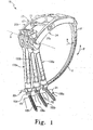
- a minimally invasive surgical system 10 that includes an installation instrument 20, three anchor extensions 130a, 130b, 130c, (collectively and individually referred to herein as anchor extensions 130) and a connecting element 90.
- Anchor extensions 130a, 130b, 130c are releasably mountable to respective ones of the anchors 100a, 100b, 100c (collectively and individually also referred to herein as anchor 100.)
- Installation instrument 20 is movable about a pivot axis A defined at a coupling location with the anchor extensions 130. Movement of installation instrument 20 swings inserter arm 31 along an arcuate insertion path P defined by insertion axis I.
- path P is defined by a radius R extending to insertion axis I from pivot axis A.
- Connecting element or brace 90 can be an elongated rod or shaft curved along its length with a radius of curvature that corresponds generally to the radius of curvature of inserter arm 31.
- connecting element 90 can include any configuration known for a rod, implant, or fastener, so long as connecting element 90 is insertable using installation instrument 20.
- connecting element 90 can be non-rigid, elastic and/or super-elastic and in the form of a cable, band, wire, or artificial ligament that used in tethering, guiding, or other surgical procedures.
- Connecting element 90 can be percutaneously or non-percutaneously inserted with installation instrument 20 to a location adjacent connecting element engaging portions of one or more anchors engaged to a bony structure in the body of an animal subject to stabilize the bony structure.
- connecting element 90 is a rigid rod curved along an arc that forms an extension of insertion axis I defined by inserter arm 31.
- connecting element 90 can have a curvature that differs from the curvature of insertion axis I, or can have a curvature that varies or is compounded along its length, or can be linear.
- connecting element 90 and insertion axis I can be configured to define an insertion axis by any one or any combination of mathematical relationships, including, for example, linear, exponential, logarithmic, trigonometric, geometric, parabolic, quadratic, cubic, hyperbolic, elliptic, or parametric relationships, and installation instrument 20 can be adapted or structured to provide insertion along any such insertion pathway.
- Connecting element 90 in FIG. 1 is inserted via the installation instrument 20 to a location adjacent anchors 100 in order to stabilize the respective vertebrae V1, V2 and V3.
- the installation instrument 20 can employ any type of fixed geometric relationship to insert connecting element 90 into the patient.
- This fixed geometric relationship can be governed any one or combination of a pinned joint, a cam, a four-bar linkage, a guide member that provides a path for translational movement of connecting element 90, or any other mechanical relationship that would occur to those skilled in the art.
- Anchors 100 include a bone engaging portion 102 and a connecting element engaging portion 104.
- bone engaging portion 102 is a bone screw with a threaded shank to engage the bony structure of the underlying vertebrae.
- Connecting element engaging portion 104 is a receiver having a pair of opposing arms defining a longitudinal passage alignable along insertion axis I. The arms further define a proximal/distally extending opening that opens at a proximal end of the arms to receive a set screw (not shown) to secure connecting element 90 in the passage.
- Bone engaging portion 102 can be pivotally received in connecting element engaging portion 104 through the distal opening thereof, and structured to interact therewith to provide anchor 100 with multi-axial capabilities that permits either a selected number of positions or infinitely numbered of positions of bone engaging portion 102 relative to connecting element engaging portion 104.
- the bone engaging portion can be in the form of a spike, staple, fusion device, cannulated screw, fenestrated screw, interbody device, intrabody device, clamp, plate, suture anchor, bolt, pin or other bone engaging member.
- the connecting element engaging portion can be in the form of a saddle, yoke, eye-bolt or through-hole, side opening member, bottom opening member, top-opening member, eyelet, or any other structure engageable to the connecting element.
- Inserter 24 includes inserter arm 31 extending from a mounting portion 22.
- Mounting portion 22 includes a pair of support arms 26a, 26b that extend from proximal end portions of anchor extensions 130 when mounted thereto.
- Support arms 26a, 26b extend to a junction portion 28, providing mounting portion 22 with a general U or V-shape when viewed from above ( Fig. 3 .)
- support arms 26a, 26b include an upward or proximally oriented convex curvature.
- Inserter arm 31 extends from junction portion 28 along insertion axis I, and is oriented transversely to support arms 26a, 26b.
- First support arm 26a is fixed relative to junction portion 28 at fixed end 32a. Junction portion 28 extends from first support arm 26a to coupling portion 30 adjacent second support arm 26b. Second support arm 26b includes a pivot end 32b received in coupling portion 30 and pivotally secured thereto with a pin, living hinge, or other suitable pivotal coupling arrangement. Second support arm 26b extends from pivot end 32b to an anchor extension engaging end 34b. First support arm 26a extends from fixed end 32a to an anchor extension engaging end 34a. Engaging ends 34a, 34b each include an extension engaging member 36a, 36b, respectively.
- Engaging members 36a, 36b are pivotally mounted on respective ones of posts 38a, 38b extending from support arms 26a, 26b, and are positioned to face one another between support arms 26a, 26b.
- Engaging member 36a includes a mounting pin 37a projecting therefrom, and engaging member 36b includes a mounting receptacle 37b extending therein.
- each of the engaging members 36a, 36b includes a mounting pin, or that each includes a mounting receptacle.
- First support arm 26a is joined to second support arm 26b with a clamping assembly.
- the clamping assembly includes a pivotal clamping arm 40 extending between support arms 26a, 26b.
- Clamping arm 40 is pivotally connected at a first end to a lever 42.
- Lever 42 is further pivotally coupled to support arm 26a with a pin 29 offset from its pivotal connecting with clamping arm 40 to allow translation of clamping arm 40 relative to support arm 26a.
- Clamping arm 40 is pivotally connected at its second end to a wheel 44.
- Wheel 44 is rotatably mounted to second support arm 26b, and includes a circumferential opening 45 extend partly therearound through which clamping arm 40 extends.
- the second end of clamping arm 40 is coupled to wheel 44 at a location spaced radially from the rotational center of wheel 44.
- a release mechanism 58 engages wheel 44 to maintain wheel 44 in a desired rotational position relative to support arm 26b.
- second support arm 26b is pivoted toward first support arm 26a against the bias of clamping arm 40 to bring anchor engaging ends 34a, 34b toward one another.
- Mounting pin 37a is rotatably received in a receptacle (not shown) of anchor extension 130c, while mounting receptacle 37b rotatably receives a pin 131 extending from anchor extension 130c.
- the toggling capabilities of engaging members 36a, 36b permits the pins and receptacles to self-align with one another as the clamping force is applied to anchor extensions 130 to ensure a rotatable connecting between inserter 24 and the anchors extensions 130.
- Inserter 24 is thus pivotally mounted to the anchor extensions 130 and movable relative thereto to deliver the connecting element from a remote location to a location more proximate the anchors 100, as shown in Fig. 1 .
- Clamping arm 40 is pivotally coupled to lever 42 so that movement of lever 42, as indicated by arrow C ( Figs. 3 , 4 ) toward a closed position, shown in Fig. 5 , translates the first end of clamping arm 40 relative to first support arm 26a as arms 26a, 26b are moved toward one another to secure extensions 130 therebetween.
- Lever 42 can be pivoted until it is flush alongside first arm 26a.
- the bowed clamping arm 40 pushes against the first end of lever 42 to bias it to the closed position as viewed in Fig. 5 .
- This provides a firm locked, rotational engagement of the support arms 26a, 26b to anchor extensions 130.
- lever 42 can be moved in the direction of arrow O against the bias of clamping arm 40 to allow support arms 26a, 26b to move away from one another a sufficient distance to release the anchor extensions 130 from therebetween.
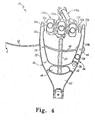
- second arm 26b permits inserter 24 to be readily employed in procedures using three anchor extensions, as shown in Figs. 1 , 4 and 5 , and procedures using two anchor extensions, as shown in Fig. 6 .
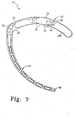
- the spacing between support arms 26a, 26b can be adjusted to accommodate two anchor extensions by depressing release mechanism 58, as shown in Fig. 7 .
- This displaces a wheel engaging portion 59 that is normally biased onto engagement with wheel 44 to maintain its rotational positioning.
- wheel 44 can rotate in a direction R about its rotational connection with second support arm 26b to displace the second end of clamping arm 40 through support arm 26b to location 43 as second support arm 26b is pivoted about coupling portion 30 toward first support arm 26a.
- Wheel 44 allows the effective length of clamping arm 40 between support arms 26a, 26b to be adjusted accommodate the change in spacing between support arms 26a, 26b necessary to securely clamp two anchor extensions 130 therebetween. After wheel 44 is rotated to the adjusted position, release mechanism 58 is released and re-engages wheel 44 to maintain it in the adjusted position.
- the support arms and clamping assembly can be configured to clamp about a single anchor extension, or four or more anchor extensions.
- Support arms 26a, 26b come together at a junction portion 28.
- Junction portion 28 defines a hand-hole 46 to facilitate manual grasping of the inserter 24 and facilitates pivoting movement of it about anchor extensions 130.
- actuating member 52 pivotally coupled at junction portion 28 that operates a locking mechanism 50 to remotely secure and release the connecting element 90 to installation instrument 20. Actuating member 52 can be accessed in handle-hole 46 to pivot it between locked and unlocked positioned to selectively engage and release the connecting element 90 adjacent a distal end 48 of inserter arm 31, as discussed further below.
- Locking mechanism 50 is shown in Fig. 7 in a locked condition and with connecting element securing member 60 removed therefrom.
- the locking mechanism 50 is unlocked by pivoting actuating member 52 about its pivotal connection 33 with junction portion 28. This in turn displaces securing member 60 so that a securing end 62 extends from distal end 48 of inserter arm 31.
- a trailing end of connecting element 90, or some other portion of the connecting element can be positioned in securing end 62.
- actuating member 52 is moved to the locked position of Fig.
- securing member 60 translates in bore 78 of inserter arm 31 and draws securing end 62 therein. This in turn clamps the connecting element in securing end 62, securing it to the distal end 48 of inserter arm 31.
- Securing end 62 can be provided as a collet with bifurcated walls 62a, 62b as shown in Fig. 12 or other radially expandable and contractable structure to grippingly engage connecting element 90 thereto.
- Securing member 60 includes an elongated body 64 extending from securing end 62 to a latching end 66.
- a reduced cross-section portion 68 is provided adjacent latching end 66 to allow additional flexibility thereto, for reasons discussed further below.
- Latching end 66 includes opposite notches 70a. 70b positioned below an enlarged head portion 69. Notches 70a, 70b receiving a latching mechanism 72 to releasably couple securing member 60 in inserter arm 31, as discussed further below.
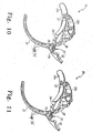
- Fig. 10 shows a latching mechanism 72 comprising a portion of locking mechanism 50 in a latched position.
- Latching mechanism 72 includes a housing 76 and a latch member 74.
- Latch member 74 is movable relative to housing 76 between the latched position and an unlatched position shown in Fig. 11 .
- latch member 74 engages head portion 69 and locks securing member 60 in inserter arm 31.
- securing member 60 can be moved relative to inserter arm 31 to position head portion 69 into and out of housing 76. This allows securing member 60 to be removed for sterilization after a surgical procedure, or to allow replacement of securing member 60 without replacement of the entire inserter 24.
- instrument 20 can be sterilized more effectively with securing member 60 removed since bore 78 of inserter arm 31 is unobstructed, facilitating removal of any biomaterial that may be trapped therein.
- Sidewall holes 35 in inserter arm 31 are in communication with the central bore 78 thereof, further facilitating cleaning and sterilization.
- Housing 76 is pivotally coupled to actuating member 52 at connection 75, as shown in Fig. 9 .
- Housing 76 includes sidewalls 80 forming a central slot 88 therebetween.
- a lower extension 86 extends between sidewalls 80 adjacent a frontal end thereof and adjacent a lower end of slot 88.
- An inner wall 90 extends between sidewalls 80 along an inner side of housing 76.
- a central projection 82 extends from inner wall 90 centrally between sidewalls 80, forming a space between each of the sidewalls 80 and projection 82.
- Latch member 74 includes an upper portion 92 and an integral lower latching end 94.
- Upper portion 92 includes a through-hole 95 to receive a pin (not shown) to secure latch member 74 to housing 76 when in the locked position.
- Lower latching end 94 is pivotally coupled to housing 76, and includes opposing arms that straddle central projection 82. The arms of latching end 94 include a space therebetween that defines a receiving portion 96 along a portion thereof, and latching projections 98 adjacent to receiving portion 96.
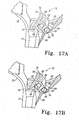
- Figs. 17A-17D show sequential steps of locking securing member 60 in latching mechanism 72.
- the upper end 66 of securing member 60 is shown diagrammatically in Figs. 17A-17D .
- upper end 66 projects from bore 78 of inserter arm 31, and in Fig. 17B is advanced toward central projection 82 of housing 76.
- the relative positioning between latch member 74 and housing 76 aligns receiving portion 96 with recess 84 of central projection 82 in the unlatched position.
- Receiving portion 96 is sized to allow passage of enlarged head 69 therethrough.
- FIG. 17C upper end 66 of securing member 60 is seated in contact with or adjacent to central projection 82 in recess 84.
- Latch member 74 can then be rotated to the locked position shown in Fig. 17D .
- latching projections 98 are received in notches 70a, 70b formed in the underside of enlarged head 69.
- Latching projections 98 capture securing member 60 in latching mechanism 72.
- a pin (not shown) can be positioned through holes 95 of latch member 74 and engaged to housing 76 to secure latch member 74 in the latched position. If disassembly of securing member 60 is desired, the steps are reversed, and securing member 60 can be pulled through bore 78 of inserter arm 31 for removal therefrom.
- securing end 62 projects from distal end 48 of inserter arm 31 as shown in Figs. 8, 9 .
- the connecting element 90 can be positioned in securing end 62, and actuating member 52 is pivoted from its unlocked position, as shown in Figs. 8-9 , to its locked position, such as shown in Fig. 1 , to securely engage connecting element 90 to inserter arm 31.
- the connection of housing 76 to actuating member 52 allows housing 76, and thus securing member 60, to follow actuating member 52 as it is moved between its locked and unlocked positions.
- actuating member 52 is contoured to conform to the body of inserter 24 when in the locked position to provide a low profile configuration and minimize or eliminate protrusions or abrupt edges that may interfere with the operation of installation instrument 20.
- housing 76 is formed so that it lies flush with the outer surface of inserter arm 31 when actuating member 52 is moved to the locked position, as shown in Figs. 1 and 7 , for example.
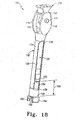
- Anchor extension 130 includes an outer sleeve 132 extending along an elongated body 134.
- Elongate body 134 includes elongated slots 136, 137 opening along opposite sides thereof. Slots 136, 137 extend between a proximal end 139 and a distal end 138.
- Body 134 includes a length extending from a distal end portion 140 to an enlarged proximal end portion 142.
- Proximal end portion 142 includes opposite flat wall surfaces 144 to facilitate positioning of adjacent extensions 130 in side-by-side relation while minimizing the overall width of the assembled extensions 130.
- Rounded wall surfaces 146 extend between flat wall surfaces 144.
- Anchor extension 130 further includes an inner sleeve 150 positioned in a bore extending through outer sleeve 132.
- Inner sleeve 150 includes a tubular body 158 defining distal fingers 154, 155. Fingers 154, 155 are separated by a slot to facilitate fingers 154, 155 moving toward and away from another to capture anchor 100 therebetween.
- Fingers 154, 155 include flanged ends 164, 165, respectively, at their distal ends that project outwardly for abutting engagement with distal end portion 140 of outer sleeve 132.
- Flanged ends 164,165 further each include a projection or nub 166 (only one shown) that engage an adjacent recess in anchor 100 to facilitate securely mounting anchor extension 130 to anchor 100.
- Fingers 154, 155 also each include a projecting member 152, 153, respectively, extending therefrom through respective ones of the slots 136, 137. Projecting members 152, 153 contact the distal end 138 of slots 136, 137 to limit the proximal displacement of outer sleeve 132 relative to inner sleeve 150, as shown in Figs. 20A and 20B . In this open position, fingers 154, 155 are spaced from one another to receive anchor 100 therebetween. In Fig. 20C , outer sleeve 132 is advanced distally along fingers 154, 155 to bias flanged ends 164, 165 into engagement with anchor 100.
- the outer surfaces of fingers 154, 155 can be ramped to provide a larger cross-section adjacent flanged ends 164, 165, facilitating positive closure of the fingers 154, 155 against anchor 100.
- Distal portion 140 of outer sleeve 132 can contact flanged ends 164, 165 to prevent further distal displacement of outer sleeve 132 about inner sleeve 150.
- the spacing 160 between the distal ends of projecting members 152, 153 and the proximal ends of flanged ends 164,165 defines a distance along which sleeves 132, 150 move relative to one another between the open and clamping positions.
- anchor extension 130 is shown clampingly engaged to connecting element engaging portion 104 of anchor 100 between fingers 154, 155.
- the slot between the fingers 154, 155 is aligned with the passage 106 defined between arms 107, and fingers 154, 155 are aligned with and positioned about respective ones of the arms 107.
- Nubs 166 can be received in recesses (not shown) formed in arms 107 to further resist dislodgement of anchor 100 from anchor extension 130.
- bone engaging portion 102 remains free pivot relative to connecting element engaging portion 104 should anchor 100 be provided in multi-axial form.
- Figs. 19A-19C show in partial section proximal end portion 142 of anchor extension 130 and a toggle mechanism 170 that locks sleeves 132, 150 to one another in the clamping position, and that also facilitates unlocking of sleeves 132, 150 when it is desired to remove anchor extension 130 from anchor 100.
- Toggle mechanism 170 includes a body between sleeves 132, 150 that has a proximal gripping portion 172 and an intermediate collar 174 extending at least partially thereabout. In the locking position of Fig. 19A , toggle latches 176 engage collar 174.
- a distal portion 178 of toggle mechanism 170 includes a proximally oriented taper that extends from a distal end 179 toward the proximal end.
- Buttons 180 are pivotally coupled to proximal end portion 142 of outer sleeve 132 with pins 182. Buttons 180 extend from a distal end 184 to a proximal end 186. Distal ends 184 are biased away from outer sleeve 132 with respective button springs 188. Proximal ends 186 each include a V-shaped recess 190 that interdigitates with a correspondingly shaped recess 192 of the adjacent toggle latch 176. Toggle latch 176 includes a lip 194 that engages a proximally oriented surface of collar 174 in the locked condition. This engagement locks toggle mechanism 170 in position relative to inner sleeve 150 and outer sleeve 132, preventing toggle mechanism 170 from being displaced proximally therefrom.
- Toggle mechanism 170 further includes sleeve latches 200 positioned between respective ones of the toggle buttons 180 and extending therethrough to inner sleeve 150.
- Sleeve latches 200 each include a projection 204 forming a proximally oriented lip that, in the locked position, is received in an adjacent notch 158 formed in the outer surface of inner sleeve 150.
- Latch springs 202 bias the respective sleeve latches 200 toward inner sleeve 150 to maintain the locked condition between sleeves 132, 150 when latch springs 202 are aligned with notches 158.
- Sleeve latches 200 include an inner surface 201 positioned along and in contact with tapered distal portion 178 of toggle mechanism 170.
- sleeves 132, 150 are locked relative to one another in the clamping position (as shown in Figs. 18 and 20C ) to prevent sleeves 132, 150 from being moved relative to one another.
- buttons 180 are pressed against the bias of button springs 188, causing proximal ends 186 to rotate about the respective pins 182. This in turn displaces toggle latches 176 away from collar 174 until lip 194 is no longer engaged therewith.
- proximal gripping portion 172 to be pulled proximally along the longitudinal axis 139 of anchor extension 130 to displace toggle mechanism 170 relative to inner sleeve 150 and outer sleeve 132.
- distal ramped portion 178 acts to displace sleeve latches 200 away from inner sleeve 150.
- the ramped surfaces of tapered portion 178 gradually compress button springs 202 until projections 204 are displaced out of the respective notches 158.
- outer sleeve 132 is free to slide proximally relative to inner sleeve 150 until distal end portion 140 contacts projecting members 152, 153. Fingers 154, 155 are then free to move away from one another a sufficient amount to receive anchor 100 therebetween or to release an anchor 100 secured therebetween.
- One type of surgical technique is directed to spinal surgery for positioning an elongated connecting element along one or more vertebral levels to provide spinal stabilization.
- a number of anchors 100 are selected according to the number of vertebral levels to be instrumented. For example, a single level procedure may include an anchor engaged to each of two vertebrae, or a two level procedure may include an anchor engaged to each of three vertebrae.
- anchors 100 can be engaged to the respective vertebrae.
- the anchors 100 can be screws engaged in the pedicles of the vertebrae.
- Anchors 100 can be positioned into the patient through one or more minimally invasive access portals, formed by an incision, cannula, or retractor system, for example.
- the anchor extensions can be clamped to the anchors after the anchors are engaged to the vertebrae.
- the anchors can be clamped to the extensions, and then delivered through the access portal or portals for engagement with the respective vertebrae. Placement of the anchors can be facilitated using a guidewire, image guided surgery system, fluoroscopic imaging, X-rays, CT scans, endoscopic viewing systems, microscopic viewing systems, loupes, and/or naked eye visualization, for example.
- extensions 130 With the anchors 100 engaged to the vertebrae and with extensions 130 extending therefrom, extensions 130 have a length sufficient to extend from the patient so that their proximal ends are accessible for mounting inserter 24 thereto. Extensions 130 are manipulated so that their proximal ends are placed in side-by-side relation, and mounting portion 22 of inserter 24 is positioned so that arms 26 can be manipulated to engage one, two, or three more extensions 130 therebetween. Connecting element 90 can be engaged to inserter arm 31 if not already so engaged. Inserter 24 can then be pivoted about the proximal ends of extensions 130 to place connecting element 90 to a location adjacent anchors 100.
- a trocar Prior to placement of connecting element 90, a trocar can be engaged to inserter 24 and moved into the patient by pivoting inserter 24 about extensions 130 along the insertion axis I from a location outside the patient, through skin and/or tissue of the patient, and to anchors 100. Inserter 24 can be pivoted in the reverse direction to withdraw the trocar. The trocar can then be removed, and connecting element 90 engaged to the inserter 24 to move it along insertion path I formed in the patient by the trocar until the connecting element extends between anchor 100 and to the connecting element engaging portions 104 thereof.
- connecting element 90 can be tapered or pointed to facilitate puncture and/or tunneling through the skin and tissue of the patient, either to form a path or to be inserted along a path formed by a trocar. Placement of the connecting element 90 can be monitored and/or confirmed using any of the visualization techniques discussed above.
- Connecting element 90 can be remotely disengaged from inserter arm 31 by manipulating actuating member 52 to release securing end 62 of securing member 60 from connecting element 90. Inserter 24 can then be withdrawn from the patient by pivoting it about extensions 130 in the reverse direction. Set screws or other securing members can be delivered through extensions 130 with a driving instrument, and engaged with respective ones of the anchors 100 to secure connecting element 90 to anchors 100. Extensions 130 can then be unclamped from the respective anchors 100 by manipulating toggling mechanism 170 as discussed above.
- One or more other connecting elements can be similarly engaged to the spinal column along the same vertebral level or levels, or along other vertebral levels.
- Other procedures can also be completed in conjunction with the stabilization procedure, including discectomy, interbody fusion, artificial disc replacement, bone removal, tissue removal, intravertebral reduction, joint replacement, annular repair, and/or any other spinal surgical procedures.
Abstract
Description
- Various devices and methods for stabilizing bone structures have been used for many years. For example, the fracture of an elongated bone, such as a femur or humerus, can be stabilized by securing a plate to the fractured bone across the fracture. The plate extends across the fractured area and thus stabilizes the fractured components of the bones relative to one another in a desired position. When the fracture heals, the plate can be removed or left in place, depending on the type of plate that is used.
- Another type of stabilization technique uses one or more elongated rods extending between components of a bony structure and secured to the bony structure to stabilize the components relative to one another. The components of the bony structure are exposed and one or more bone engaging fasteners are placed into each component. The elongated rod is then secured to the bone engaging fasteners in order to stabilize the components of the bony structure.
- One problem associated with the above described stabilization structures is that the skin and tissue surrounding the surgical site must be cut, removed, and/or repositioned in order for the surgeon to access the location where the stabilization device is to be installed. This repositioning of tissue causes trauma, damage, and scarring to the tissue. There are also risks that the tissue will become infected and that a long recovery time will be required after surgery for the tissue to heal.
- Minimally invasive surgical techniques are particularly desirable in, for example, spinal and neurosurgical applications because of the need for access to locations deep within the body and the presence of vital intervening tissues. The development of percutaneous minimally invasive spinal procedures has yielded a major improvement in reducing recovery time and post-operative pain because they require minimal, if any, muscle dissection and can be performed under local anesthesia. These benefits of minimally invasive techniques have also found application in surgeries for other locations in the body where it is desirable to minimize tissue disruption and trauma. There remains a need for further improvements instruments and methods for stabilizing bony structures using minimally invasive techniques.
-
WO01/28436A1 -
US2005/0131408A1 discloses a percutaneous access device including an inner tube and an outer tube wherein one or more resilient tabs are provided to limit the relative motion of the inner and outer tubes. -
DE20013905U1 discloses a system in which relative movement between inner and outer sleeves is locked by using a locking sleeve and ball arrangement. - The invention is defined in the appended claims.
- Systems for positioning a connecting element adjacent the spinal column in minimally invasive surgical procedures includes an installation instrument with one or more anchor extensions removably engaged to one or more anchors engageable to the spinal column and an inserter movably mounted to the anchor extensions. The inserter is operable to position a connecting element engaged thereto to a location adjacent the one or more anchors in a minimally invasive surgical procedure.
- In one form, a single instrument is readily adaptable for spinal stabilization and other procedures employing varying numbers of anchor extensions:
- In another form, the installation instrument includes a quick-release actuating mechanism that allows a connecting element to be conveniently and remotely engaged and disengaged to an inserter instrument.
- In a further form, the installation instrument includes an inserter arm with a securing member for securing a connecting element thereto. The securing member can be conveniently disassembled from and reassembled with the inserter arm to facilitate cleaning and repair of the installation instrument.
- In another form, the installation instrument includes one or more anchor extensions having a toggle mechanism that facilitates engagement and disengagement of the anchor extension to an anchor.
- Related features, aspects, embodiments, objects and advantages of the present invention will be apparent from the following description.
-
-
Figures 1 ,4-6 and18-20C illustrate embodiments of the present invention. The embodiments shown infigures 2, 3 and7-17D do not form part of this invention.Fig. 1 is a perspective view of a system for positioning a connecting element in a patient in minimally invasive surgical procedures. -
Fig. 2 is a perspective view of an inserter of the system ofFig. 1 in an open condition. -
Fig. 3 is a top plan view of the inserter ofFig. 2 . -
Fig. 4 is the view ofFig. 3 with three anchor extensions positioned between open support arms of the inserter. -
Fig. 5 is the view ofFig. 4 with the support arms of the inserter clamped to the anchor extensions. -
Fig. 6 is a top plan view of the inserter clamped to a pair of anchor extensions. -
Fig. 7 is a side view of the inserter with a wheel release mechanism depressed. -
Fig. 8 is a perspective view of the inserter with an actuating member in an unlocked position. -
Fig. 9 is a side view of the inserter ofFig. 8 . -
Fig. 10 is another perspective view of the inserter with the actuating member in an unlocked position and a latch mechanism in a locked position. -
Fig. 11 is the inserter ofFig. 10 with the latch mechanism in an unlocked position. -
Fig. 12 is a perspective view of a securing member comprising a portion of the inserter. -
Fig. 13 is an enlarged elevation view of an upper end of the securing member ofFig. 12 . -
Fig. 14 is a view looking at a side of the upper end from itsFig. 13 orientation. -
Fig. 15 is a partial perspective view in partial section of the latch mechanism of the inserter in a latched position. -
Fig. 16 is the view ofFig. 15 with the latch mechanism in an unlatched position. -
Figs. 17A-17D show the latch mechanism in partial section and steps for locking the securing member to the latch mechanism. -
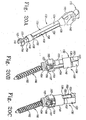
Fig. 18 is a perspective view of an anchor extension comprising a portion of the system ofFig. 1 . -
Figs. 19A-19C are elevation views in partial section of a proximal portion of the anchor extension ofFig. 18 showing various positions of a toggle mechanism for securing inner and outer sleeves of the extension in various positions relative to one another. -
Figs. 20A-20C are perspective views showing the anchor extension being secured to an anchor. - For the purposes of promoting an understanding of the principles of the invention, reference will now be made to the embodiments illustrated in the drawings and specific language will be used to describe the same. It will nevertheless be understood that no limitation of the scope of the invention is thereby intended.
- Systems for insertion of a connecting element for connection with anchors engaged to bony parts of the body are provided. In one form, the systems include at least one anchor extension extending from at least one anchor engaged to the bony part of the body. An installation instrument is mountable to the at least one anchor extension and operable to position a connecting element from a location remotely positioned from the at least one anchor to a location adjacent to or within the anchor where the connecting element can be secured to the anchor. The anchor and connecting element can each be positioned into the patient in minimally invasive procedures, minimizing trauma and surgical risks to the patient and promoting rapid post-operative recovery. However, applications in non-minimally invasive surgeries are also contemplated.
- In another form, the systems include an installation instrument mountable to at least one extension extending from an anchor engaged to the spinal column or other anatomical structure in a patient. The installation instrument is movable relative to the anchor extension to position a connecting element adjacent to the anchor in a minimally invasive procedure. The installation instrument includes a quick-release coupling mechanism for remotely engaging and disengaging the connecting element to the installation instrument.
- In a further form, the systems include an installation instrument mountable to at least one extension extending from an anchor engaged to the spinal column or other anatomical structure in a patient. The installation instrument is movable relative to the anchor extension to position a connecting element adjacent to the anchor in a minimally invasive procedure. The installation instrument includes a connecting element securing mechanism that can be readily disassembled from and assembled to the installation instrument for sterilization and/or replacement.
- In another form, the systems include an installation instrument mountable to at least one extension extending from an anchor engaged to the spinal column or other anatomical structure in a patient. The installation instrument is movable relative to the anchor extension to position a connecting element adjacent to the anchor in a minimally invasive procedure. The installation instrument includes a mounting portion that is readily adaptable to engage one, two, three or more anchor extensions therebetween depending on the number of anchors employed in the procedure.
- In yet another form, the systems include an installation instrument mountable to at least one extension extending from an anchor engaged to the spinal column or other anatomical structure in a patient. The installation instrument is movable relative to the anchor extension to position a connecting element adjacent to the anchor in a minimally invasive procedure. The at least one anchor extensions include a toggle mechanism that is structured to provide rapid and reliable remote engagement and disengagement of an anchor to a distal end of the anchor extension.
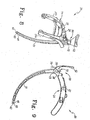
- Referring now to
Fig. 1 , there is shown a minimally invasivesurgical system 10 that includes aninstallation instrument 20, threeanchor extensions element 90.Anchor extensions anchors anchor 100.)Installation instrument 20 is movable about a pivot axis A defined at a coupling location with theanchor extensions 130. Movement ofinstallation instrument 20 swings inserterarm 31 along an arcuate insertion path P defined by insertion axis I. In the illustrated embodiment, path P is defined by a radius R extending to insertion axis I from pivot axis A. - Connecting element or brace 90 can be an elongated rod or shaft curved along its length with a radius of curvature that corresponds generally to the radius of curvature of
inserter arm 31. However, it should be understood that it is contemplated that connectingelement 90 can include any configuration known for a rod, implant, or fastener, so long as connectingelement 90 is insertable usinginstallation instrument 20. Further, connectingelement 90 can be non-rigid, elastic and/or super-elastic and in the form of a cable, band, wire, or artificial ligament that used in tethering, guiding, or other surgical procedures. Connectingelement 90 can be percutaneously or non-percutaneously inserted withinstallation instrument 20 to a location adjacent connecting element engaging portions of one or more anchors engaged to a bony structure in the body of an animal subject to stabilize the bony structure. - In the illustrated embodiment, connecting
element 90 is a rigid rod curved along an arc that forms an extension of insertion axis I defined byinserter arm 31. However, it is contemplated that connectingelement 90 can have a curvature that differs from the curvature of insertion axis I, or can have a curvature that varies or is compounded along its length, or can be linear. The curvature of connectingelement 90 and insertion axis I can be configured to define an insertion axis by any one or any combination of mathematical relationships, including, for example, linear, exponential, logarithmic, trigonometric, geometric, parabolic, quadratic, cubic, hyperbolic, elliptic, or parametric relationships, andinstallation instrument 20 can be adapted or structured to provide insertion along any such insertion pathway. Connectingelement 90 inFIG. 1 is inserted via theinstallation instrument 20 to a locationadjacent anchors 100 in order to stabilize the respective vertebrae V1, V2 and V3. Theinstallation instrument 20 can employ any type of fixed geometric relationship to insert connectingelement 90 into the patient. This fixed geometric relationship can be governed any one or combination of a pinned joint, a cam, a four-bar linkage, a guide member that provides a path for translational movement of connectingelement 90, or any other mechanical relationship that would occur to those skilled in the art. -
Anchors 100 include abone engaging portion 102 and a connectingelement engaging portion 104. In the illustrated embodiment,bone engaging portion 102 is a bone screw with a threaded shank to engage the bony structure of the underlying vertebrae. Connectingelement engaging portion 104 is a receiver having a pair of opposing arms defining a longitudinal passage alignable along insertion axis I. The arms further define a proximal/distally extending opening that opens at a proximal end of the arms to receive a set screw (not shown) to secure connectingelement 90 in the passage.Bone engaging portion 102 can be pivotally received in connectingelement engaging portion 104 through the distal opening thereof, and structured to interact therewith to provideanchor 100 with multi-axial capabilities that permits either a selected number of positions or infinitely numbered of positions ofbone engaging portion 102 relative to connectingelement engaging portion 104. - Other forms for
anchors 100 are contemplated, including uni-axial and uni-planar forms. The bone engaging portion can be in the form of a spike, staple, fusion device, cannulated screw, fenestrated screw, interbody device, intrabody device, clamp, plate, suture anchor, bolt, pin or other bone engaging member. The connecting element engaging portion can be in the form of a saddle, yoke, eye-bolt or through-hole, side opening member, bottom opening member, top-opening member, eyelet, or any other structure engageable to the connecting element. - Referring now further to
Figs. 2-3 , there is shown aninserter 24 ofinstallation instrument 20 in an open condition and withoutanchor extensions 130 orbrace 90.Inserter 24 includesinserter arm 31 extending from a mountingportion 22. Mountingportion 22 includes a pair ofsupport arms anchor extensions 130 when mounted thereto.Support arms junction portion 28, providing mountingportion 22 with a general U or V-shape when viewed from above (Fig. 3 .) When viewed from the side (Fig. 7 ),support arms Inserter arm 31 extends fromjunction portion 28 along insertion axis I, and is oriented transversely to supportarms -
First support arm 26a is fixed relative tojunction portion 28 atfixed end 32a.Junction portion 28 extends fromfirst support arm 26a tocoupling portion 30 adjacentsecond support arm 26b.Second support arm 26b includes apivot end 32b received incoupling portion 30 and pivotally secured thereto with a pin, living hinge, or other suitable pivotal coupling arrangement.Second support arm 26b extends frompivot end 32b to an anchorextension engaging end 34b.First support arm 26a extends from fixedend 32a to an anchorextension engaging end 34a. Engaging ends 34a, 34b each include anextension engaging member members posts support arms support arms member 36a includes a mountingpin 37a projecting therefrom, and engagingmember 36b includes a mountingreceptacle 37b extending therein. Other arrangements contemplate that each of the engagingmembers -
First support arm 26a is joined tosecond support arm 26b with a clamping assembly. The clamping assembly includes apivotal clamping arm 40 extending betweensupport arms arm 40 is pivotally connected at a first end to alever 42.Lever 42 is further pivotally coupled to supportarm 26a with apin 29 offset from its pivotal connecting with clampingarm 40 to allow translation of clampingarm 40 relative to supportarm 26a. Clampingarm 40 is pivotally connected at its second end to awheel 44.Wheel 44 is rotatably mounted tosecond support arm 26b, and includes acircumferential opening 45 extend partly therearound through which clampingarm 40 extends. The second end of clampingarm 40 is coupled towheel 44 at a location spaced radially from the rotational center ofwheel 44. Arelease mechanism 58 engageswheel 44 to maintainwheel 44 in a desired rotational position relative to supportarm 26b. - When
support arms Figs. 4-5 ,second support arm 26b is pivoted towardfirst support arm 26a against the bias of clampingarm 40 to bring anchor engaging ends 34a, 34b toward one another. Mountingpin 37a is rotatably received in a receptacle (not shown) ofanchor extension 130c, while mountingreceptacle 37b rotatably receives apin 131 extending fromanchor extension 130c. The toggling capabilities of engagingmembers extensions 130 to ensure a rotatable connecting betweeninserter 24 and theanchors extensions 130.Inserter 24 is thus pivotally mounted to theanchor extensions 130 and movable relative thereto to deliver the connecting element from a remote location to a location more proximate theanchors 100, as shown inFig. 1 . - Clamping
arm 40 is pivotally coupled to lever 42 so that movement oflever 42, as indicated by arrow C (Figs. 3 ,4 ) toward a closed position, shown inFig. 5 , translates the first end of clampingarm 40 relative tofirst support arm 26a asarms extensions 130 therebetween.Lever 42 can be pivoted until it is flush alongsidefirst arm 26a. The bowed clampingarm 40 pushes against the first end oflever 42 to bias it to the closed position as viewed inFig. 5 . This provides a firm locked, rotational engagement of thesupport arms extensions 130. As shown inFig. 5 ,lever 42 can be moved in the direction of arrow O against the bias of clampingarm 40 to allowsupport arms anchor extensions 130 from therebetween. - The clamping assembly and pivotal movement of
second arm 26b permitsinserter 24 to be readily employed in procedures using three anchor extensions, as shown inFigs. 1 ,4 and5 , and procedures using two anchor extensions, as shown inFig. 6 . The spacing betweensupport arms release mechanism 58, as shown inFig. 7 . This displaces awheel engaging portion 59 that is normally biased onto engagement withwheel 44 to maintain its rotational positioning. When released,wheel 44 can rotate in a direction R about its rotational connection withsecond support arm 26b to displace the second end of clampingarm 40 throughsupport arm 26b tolocation 43 assecond support arm 26b is pivoted about couplingportion 30 towardfirst support arm 26a.Wheel 44 allows the effective length of clampingarm 40 betweensupport arms support arms anchor extensions 130 therebetween. Afterwheel 44 is rotated to the adjusted position,release mechanism 58 is released and re-engages wheel 44 to maintain it in the adjusted position. Other embodiments contemplate the support arms and clamping assembly can be configured to clamp about a single anchor extension, or four or more anchor extensions. -
Support arms junction portion 28.Junction portion 28 defines a hand-hole 46 to facilitate manual grasping of theinserter 24 and facilitates pivoting movement of it aboutanchor extensions 130. There is further provided an actuatingmember 52 pivotally coupled atjunction portion 28 that operates alocking mechanism 50 to remotely secure and release the connectingelement 90 toinstallation instrument 20. Actuatingmember 52 can be accessed in handle-hole 46 to pivot it between locked and unlocked positioned to selectively engage and release the connectingelement 90 adjacent adistal end 48 ofinserter arm 31, as discussed further below. - Referring now to
Figs. 7-11 ,locking mechanism 50 will be discussed further. Lockingmechanism 50 is shown inFig. 7 in a locked condition and with connectingelement securing member 60 removed therefrom. InFigs. 8 and 9 , thelocking mechanism 50 is unlocked by pivoting actuatingmember 52 about itspivotal connection 33 withjunction portion 28. This in turn displaces securingmember 60 so that a securingend 62 extends fromdistal end 48 ofinserter arm 31. In the unlocked position, a trailing end of connectingelement 90, or some other portion of the connecting element, can be positioned in securingend 62. As actuatingmember 52 is moved to the locked position ofFig. 7 , securingmember 60 translates inbore 78 ofinserter arm 31 and draws securingend 62 therein. This in turn clamps the connecting element in securingend 62, securing it to thedistal end 48 ofinserter arm 31. Securingend 62 can be provided as a collet with bifurcatedwalls Fig. 12 or other radially expandable and contractable structure to grippingly engage connectingelement 90 thereto. - Further details of securing
member 60 are shown inFigs. 12-14 . Securingmember 60 includes anelongated body 64 extending from securingend 62 to a latchingend 66. A reducedcross-section portion 68 is provided adjacent latchingend 66 to allow additional flexibility thereto, for reasons discussed further below. Latchingend 66 includesopposite notches 70a. 70b positioned below anenlarged head portion 69.Notches latching mechanism 72 to releasablycouple securing member 60 ininserter arm 31, as discussed further below. -
Fig. 10 shows alatching mechanism 72 comprising a portion of lockingmechanism 50 in a latched position. Latchingmechanism 72 includes ahousing 76 and alatch member 74.Latch member 74 is movable relative tohousing 76 between the latched position and an unlatched position shown inFig. 11 . In the latched position,latch member 74 engageshead portion 69 andlocks securing member 60 ininserter arm 31. In the unlatched position, securingmember 60 can be moved relative toinserter arm 31 to positionhead portion 69 into and out ofhousing 76. This allows securingmember 60 to be removed for sterilization after a surgical procedure, or to allow replacement of securingmember 60 without replacement of theentire inserter 24. Furthermore,instrument 20 can be sterilized more effectively with securingmember 60 removed sincebore 78 ofinserter arm 31 is unobstructed, facilitating removal of any biomaterial that may be trapped therein. Sidewall holes 35 ininserter arm 31 are in communication with thecentral bore 78 thereof, further facilitating cleaning and sterilization. -
Figs. 15 and 16 show latching mechanism 72 in further detail.Housing 76 is pivotally coupled to actuatingmember 52 atconnection 75, as shown inFig. 9 .Housing 76 includes sidewalls 80 forming acentral slot 88 therebetween. Alower extension 86 extends betweensidewalls 80 adjacent a frontal end thereof and adjacent a lower end ofslot 88. Aninner wall 90 extends betweensidewalls 80 along an inner side ofhousing 76. Acentral projection 82 extends frominner wall 90 centrally betweensidewalls 80, forming a space between each of thesidewalls 80 andprojection 82. -
Latch member 74 includes anupper portion 92 and an integral lowerlatching end 94.Upper portion 92 includes a through-hole 95 to receive a pin (not shown) to securelatch member 74 tohousing 76 when in the locked position. Lower latchingend 94 is pivotally coupled tohousing 76, and includes opposing arms that straddlecentral projection 82. The arms of latchingend 94 include a space therebetween that defines a receivingportion 96 along a portion thereof, and latchingprojections 98 adjacent to receivingportion 96. -
Figs. 17A-17D show sequential steps of locking securingmember 60 in latchingmechanism 72. Theupper end 66 of securingmember 60 is shown diagrammatically inFigs. 17A-17D . InFig. 17A ,upper end 66 projects frombore 78 ofinserter arm 31, and inFig. 17B is advanced towardcentral projection 82 ofhousing 76. The relative positioning betweenlatch member 74 andhousing 76 aligns receivingportion 96 withrecess 84 ofcentral projection 82 in the unlatched position. Receivingportion 96 is sized to allow passage ofenlarged head 69 therethrough. - In
Fig. 17C ,upper end 66 of securingmember 60 is seated in contact with or adjacent tocentral projection 82 inrecess 84.Latch member 74 can then be rotated to the locked position shown inFig. 17D . Aslatch member 74 is rotated, latchingprojections 98 are received innotches enlarged head 69. Latchingprojections 98capture securing member 60 in latchingmechanism 72. A pin (not shown) can be positioned throughholes 95 oflatch member 74 and engaged tohousing 76 to securelatch member 74 in the latched position. If disassembly of securingmember 60 is desired, the steps are reversed, and securingmember 60 can be pulled through bore 78 ofinserter arm 31 for removal therefrom. - Once securing
member 60 is locked in position with latchingmechanism 72, securingend 62 projects fromdistal end 48 ofinserter arm 31 as shown inFigs. 8, 9 . The connectingelement 90 can be positioned in securingend 62, and actuatingmember 52 is pivoted from its unlocked position, as shown inFigs. 8-9 , to its locked position, such as shown inFig. 1 , to securely engage connectingelement 90 toinserter arm 31. The connection ofhousing 76 to actuatingmember 52 allowshousing 76, and thus securingmember 60, to follow actuatingmember 52 as it is moved between its locked and unlocked positions. - As can be seen in
Figs. 1 and7 , for example, actuatingmember 52 is contoured to conform to the body ofinserter 24 when in the locked position to provide a low profile configuration and minimize or eliminate protrusions or abrupt edges that may interfere with the operation ofinstallation instrument 20. Furthermore,housing 76 is formed so that it lies flush with the outer surface ofinserter arm 31 when actuatingmember 52 is moved to the locked position, as shown inFigs. 1 and7 , for example. - Referring now to
Figs. 18-20C , one embodiment ofanchor extensions 130 will now be described in further detail.Anchor extension 130 includes anouter sleeve 132 extending along anelongated body 134.Elongate body 134 includeselongated slots Slots proximal end 139 and adistal end 138.Body 134 includes a length extending from adistal end portion 140 to an enlargedproximal end portion 142.Proximal end portion 142 includes opposite flat wall surfaces 144 to facilitate positioning ofadjacent extensions 130 in side-by-side relation while minimizing the overall width of the assembledextensions 130. Rounded wall surfaces 146 extend between flat wall surfaces 144. -
Anchor extension 130 further includes aninner sleeve 150 positioned in a bore extending throughouter sleeve 132.Inner sleeve 150 includes atubular body 158 definingdistal fingers Fingers fingers capture anchor 100 therebetween.Fingers distal end portion 140 ofouter sleeve 132. Flanged ends 164,165 further each include a projection or nub 166 (only one shown) that engage an adjacent recess inanchor 100 to facilitate securely mountinganchor extension 130 to anchor 100. -
Fingers member slots members distal end 138 ofslots outer sleeve 132 relative toinner sleeve 150, as shown inFigs. 20A and 20B . In this open position,fingers anchor 100 therebetween. InFig. 20C ,outer sleeve 132 is advanced distally alongfingers anchor 100. The outer surfaces offingers fingers anchor 100.Distal portion 140 ofouter sleeve 132 can contact flanged ends 164, 165 to prevent further distal displacement ofouter sleeve 132 aboutinner sleeve 150. The spacing 160 between the distal ends of projectingmembers sleeves - In the illustrated embodiment of
Fig. 20C ,anchor extension 130 is shown clampingly engaged to connectingelement engaging portion 104 ofanchor 100 betweenfingers fingers passage 106 defined betweenarms 107, andfingers arms 107.Nubs 166 can be received in recesses (not shown) formed inarms 107 to further resist dislodgement ofanchor 100 fromanchor extension 130. In the clamped condition,bone engaging portion 102 remains free pivot relative to connectingelement engaging portion 104 should anchor 100 be provided in multi-axial form. -
Figs. 19A-19C show in partial sectionproximal end portion 142 ofanchor extension 130 and atoggle mechanism 170 that lockssleeves sleeves anchor extension 130 fromanchor 100.Toggle mechanism 170 includes a body betweensleeves gripping portion 172 and anintermediate collar 174 extending at least partially thereabout. In the locking position ofFig. 19A , toggle latches 176 engagecollar 174. Adistal portion 178 oftoggle mechanism 170 includes a proximally oriented taper that extends from adistal end 179 toward the proximal end. -
Buttons 180 are pivotally coupled toproximal end portion 142 ofouter sleeve 132 withpins 182.Buttons 180 extend from adistal end 184 to aproximal end 186. Distal ends 184 are biased away fromouter sleeve 132 with respective button springs 188. Proximal ends 186 each include a V-shapedrecess 190 that interdigitates with a correspondingly shapedrecess 192 of theadjacent toggle latch 176.Toggle latch 176 includes alip 194 that engages a proximally oriented surface ofcollar 174 in the locked condition. This engagement lockstoggle mechanism 170 in position relative toinner sleeve 150 andouter sleeve 132, preventingtoggle mechanism 170 from being displaced proximally therefrom. -
Toggle mechanism 170 further includes sleeve latches 200 positioned between respective ones of thetoggle buttons 180 and extending therethrough toinner sleeve 150. Sleeve latches 200 each include aprojection 204 forming a proximally oriented lip that, in the locked position, is received in anadjacent notch 158 formed in the outer surface ofinner sleeve 150. Latch springs 202 bias the respective sleeve latches 200 towardinner sleeve 150 to maintain the locked condition betweensleeves notches 158. Sleeve latches 200 include aninner surface 201 positioned along and in contact with tapereddistal portion 178 oftoggle mechanism 170. - In
Fig. 19A ,sleeves Figs. 18 and20C ) to preventsleeves outer sleeve 132 frominner sleeve 150,buttons 180 are pressed against the bias of button springs 188, causing proximal ends 186 to rotate about the respective pins 182. This in turn displaces toggle latches 176 away fromcollar 174 untillip 194 is no longer engaged therewith. This allows proximal grippingportion 172 to be pulled proximally along thelongitudinal axis 139 ofanchor extension 130 to displacetoggle mechanism 170 relative toinner sleeve 150 andouter sleeve 132. - As
toggle mechanism 170 is proximally displaced relative tosleeves portion 178 acts to displace sleeve latches 200 away frominner sleeve 150. The ramped surfaces of taperedportion 178 gradually compress button springs 202 untilprojections 204 are displaced out of therespective notches 158. Whenprojections 204 are completely removed fromnotches 158,outer sleeve 132 is free to slide proximally relative toinner sleeve 150 untildistal end portion 140contacts projecting members Fingers anchor 100 therebetween or to release ananchor 100 secured therebetween. - Various surgical techniques can be completed with the
system 10. One type of surgical technique is directed to spinal surgery for positioning an elongated connecting element along one or more vertebral levels to provide spinal stabilization. A number ofanchors 100 are selected according to the number of vertebral levels to be instrumented. For example, a single level procedure may include an anchor engaged to each of two vertebrae, or a two level procedure may include an anchor engaged to each of three vertebrae. - When the desired number of levels has been selected, anchors 100 can be engaged to the respective vertebrae. In posterior spinal surgical techniques, the
anchors 100 can be screws engaged in the pedicles of the vertebrae.Anchors 100 can be positioned into the patient through one or more minimally invasive access portals, formed by an incision, cannula, or retractor system, for example. The anchor extensions can be clamped to the anchors after the anchors are engaged to the vertebrae. Alternatively, the anchors can be clamped to the extensions, and then delivered through the access portal or portals for engagement with the respective vertebrae. Placement of the anchors can be facilitated using a guidewire, image guided surgery system, fluoroscopic imaging, X-rays, CT scans, endoscopic viewing systems, microscopic viewing systems, loupes, and/or naked eye visualization, for example. - With the
anchors 100 engaged to the vertebrae and withextensions 130 extending therefrom,extensions 130 have a length sufficient to extend from the patient so that their proximal ends are accessible for mountinginserter 24 thereto.Extensions 130 are manipulated so that their proximal ends are placed in side-by-side relation, and mountingportion 22 ofinserter 24 is positioned so that arms 26 can be manipulated to engage one, two, or threemore extensions 130 therebetween. Connectingelement 90 can be engaged toinserter arm 31 if not already so engaged.Inserter 24 can then be pivoted about the proximal ends ofextensions 130 to place connectingelement 90 to a locationadjacent anchors 100. - Prior to placement of connecting
element 90, a trocar can be engaged toinserter 24 and moved into the patient by pivotinginserter 24 aboutextensions 130 along the insertion axis I from a location outside the patient, through skin and/or tissue of the patient, and toanchors 100.Inserter 24 can be pivoted in the reverse direction to withdraw the trocar. The trocar can then be removed, and connectingelement 90 engaged to theinserter 24 to move it along insertion path I formed in the patient by the trocar until the connecting element extends betweenanchor 100 and to the connectingelement engaging portions 104 thereof. It is further contemplated that the leading end of connectingelement 90 can be tapered or pointed to facilitate puncture and/or tunneling through the skin and tissue of the patient, either to form a path or to be inserted along a path formed by a trocar. Placement of the connectingelement 90 can be monitored and/or confirmed using any of the visualization techniques discussed above. - Connecting
element 90 can be remotely disengaged frominserter arm 31 by manipulating actuatingmember 52 to release securingend 62 of securingmember 60 from connectingelement 90.Inserter 24 can then be withdrawn from the patient by pivoting it aboutextensions 130 in the reverse direction. Set screws or other securing members can be delivered throughextensions 130 with a driving instrument, and engaged with respective ones of theanchors 100 to secure connectingelement 90 toanchors 100.Extensions 130 can then be unclamped from therespective anchors 100 by manipulatingtoggling mechanism 170 as discussed above. - One or more other connecting elements can be similarly engaged to the spinal column along the same vertebral level or levels, or along other vertebral levels. Other procedures can also be completed in conjunction with the stabilization procedure, including discectomy, interbody fusion, artificial disc replacement, bone removal, tissue removal, intravertebral reduction, joint replacement, annular repair, and/or any other spinal surgical procedures.
- While the invention has been illustrated and described in detail in the drawings and foregoing description, the same is to be considered as illustrative and not restrictive in character, it being understood that only the preferred embodiment has been shown and described.
Claims (12)
- An extension (130) for use in a surgical system (10), the extension (130) releasably engageable to a connecting element engaging portion (104) of a bone anchor (100), said extension extending along a longitudinal axis and comprising:an inner sleeve (150) along the longitudinal axis including a pair of distal fingers (154, 155) engageable to said connecting element engaging portion (104);an outer sleeve (132) along the longitudinal axis about said inner sleeve, said outer sleeve moveable distally relative to said inner sleeve from a first position wherein said fingers (154,155) are movable to receive and release said connecting element engaging portion (104) therebetween and a second position wherein said outer sleeve (132) engages said fingers (154, 155) in clamping engagement with said connecting element engaging portion (104); anda toggle mechanism (170) coupled between said inner sleeve (150) and said outer sleeve (132),said toggle mechanism (170) includes a body between said inner and outer sleeves adjacent proximal ends thereof, said toggle mechanism including a proximal gripping portion (172) extending proximally from said inner and outer sleeves, andsaid toggle mechanism structured to move along the longitudinal axis between having a locked position wherein said toggle mechanism locks said outer sleeve in position relative to said inner sleeve and an unlocked position wherein said toggle mechanism is disengaged from said inner sleeve and said outer sleeve is movable relative to said inner sleeve between said first and second positions.
- The extension (130) of claim 1, wherein:said outer sleeve (132) includes opposite elongate slots (136,137) extending along said axis; andsaid inner sleeve (150) includes a pair of opposite projecting members (152,153) on said fingers (154,155) proximal of a distal end of said distal fingers (154,155), said projecting members extending through and movable along a corresponding one of said slots (136,137) as said outer sleeve is moved between said first and second positions.
- The extension (130) of claim 2, wherein:said distal fingers (154,155) include outwardly extending flanged ends (164,165), said outer sleeve including a distal end portion positioned adjacent said flanged ends when in said second position.
- The extension (130) of claim 1, wherein said toggle mechanism (170) includes at least one toggle latch engaging said outer sleeve to said toggle mechanism and lock said toggle mechanism to said outer sleeve and prevent axial movement of said toggle mechanism, said outer sleeve including at least one button (180) operable to disengage said at least one toggle latch from said toggle mechanism and permit axial movement of said toggle mechanism.
- The extension (130) of claim 4, wherein said at least one button (180) extends between a distal end (184) biased away from said outer sleeve (132) and a proximal end engaged to said toggle latch at said proximal end of said outer sleeve, said button being pivotally coupled to said outer sleeve between said distal and proximal ends thereof, wherein pressing said button at said distal end against said bias pivots said proximal end and disengages said toggle latch from said toggle mechanism.
- The extension (130) of claim 5, wherein said toggle mechanism (170) includes a collar distal of said proximal gripping portion, and said toggle latch includes a lip engageable to a proximally oriented surface of said collar to lock said toggle mechanism to said outer sleeve.
- The extension (130) of claim 5, wherein said at least one button and said at least one toggle latch includes a pair of buttons and toggle latches on opposite sides of said outer sleeve.
- The extension (130) of claim 1, wherein said toggle mechanism (170) includes at least one sleeve latch (200) extending between said outer sleeve (132) and said inner sleeve (150), said sleeve latch including a projection (204) normally biased into a notch (158) in an outer surface of said inner sleeve, said toggle mechanism displacing said projection from said notch when moved to said unlocked position.
- The extension (130) of claim 8, wherein said toggle mechanism (170) includes a proximally tapered portion contacting an inner surface of said sleeve latch, said tapered portion displacing said sleeve latch transversely to the longitudinal axis as said toggle mechanism is moved proximally and axially to said unlocked position.
- The extension (130) of claim 9, wherein said toggle mechanism (170) includes at lease one toggle latch engaging said outer sleeve (132) and said body to lock said toggle mechanism to said outer sleeve and prevent axial movement of said toggle mechanism, said outer sleeve including at least one button operable to disengage said at least one toggle latch from said body and unlock said toggle mechanism.
- The extension (130) of claim 10, further comprising a spring (188) extending between said button (180) and said sleeve latch normally biasing said sleeve latch toward said inner sleeve.
- A surgical system (10), comprising:an extension (130) of any preceding claim; andthe bone anchor (100), the bone anchor (100) including a bone engaging portion (102) and the connecting element engaging portion (104).
Applications Claiming Priority (2)
| Application Number | Priority Date | Filing Date | Title |
|---|---|---|---|
| US11/213,473 US7695475B2 (en) | 2005-08-26 | 2005-08-26 | Instruments for minimally invasive stabilization of bony structures |
| EP06789974A EP1928334B1 (en) | 2005-08-26 | 2006-08-23 | Instruments for minimally invasive stabilization of bony structures |
Related Parent Applications (2)
| Application Number | Title | Priority Date | Filing Date |
|---|---|---|---|
| EP06789974.0 Division | 2006-08-23 | ||
| EP06789974A Division EP1928334B1 (en) | 2005-08-26 | 2006-08-23 | Instruments for minimally invasive stabilization of bony structures |
Publications (3)
| Publication Number | Publication Date |
|---|---|
| EP2218417A2 EP2218417A2 (en) | 2010-08-18 |
| EP2218417A3 EP2218417A3 (en) | 2010-08-25 |
| EP2218417B1 true EP2218417B1 (en) | 2015-03-11 |
Family
ID=37503765
Family Applications (3)
| Application Number | Title | Priority Date | Filing Date |
|---|---|---|---|
| EP10164255.1A Not-in-force EP2218417B1 (en) | 2005-08-26 | 2006-08-23 | Instruments for minimally invasive stabilization of bony structures |
| EP06789974A Not-in-force EP1928334B1 (en) | 2005-08-26 | 2006-08-23 | Instruments for minimally invasive stabilization of bony structures |
| EP10164254A Not-in-force EP2218416B1 (en) | 2005-08-26 | 2006-08-23 | Instruments for minimally invasive stabilization of bony structures |
Family Applications After (2)
| Application Number | Title | Priority Date | Filing Date |
|---|---|---|---|
| EP06789974A Not-in-force EP1928334B1 (en) | 2005-08-26 | 2006-08-23 | Instruments for minimally invasive stabilization of bony structures |
| EP10164254A Not-in-force EP2218416B1 (en) | 2005-08-26 | 2006-08-23 | Instruments for minimally invasive stabilization of bony structures |
Country Status (10)
| Country | Link |
|---|---|
| US (2) | US7695475B2 (en) |
| EP (3) | EP2218417B1 (en) |
| JP (1) | JP5058165B2 (en) |
| KR (1) | KR101008466B1 (en) |
| AT (2) | ATE556663T1 (en) |
| AU (1) | AU2006283034B2 (en) |
| CA (1) | CA2620271A1 (en) |
| DE (1) | DE602006018965D1 (en) |
| ES (1) | ES2355938T3 (en) |
| WO (1) | WO2007025058A1 (en) |
Families Citing this family (155)
| Publication number | Priority date | Publication date | Assignee | Title |
|---|---|---|---|---|
| US6530929B1 (en) | 1999-10-20 | 2003-03-11 | Sdgi Holdings, Inc. | Instruments for stabilization of bony structures |
| US7833250B2 (en) | 2004-11-10 | 2010-11-16 | Jackson Roger P | Polyaxial bone screw with helically wound capture connection |
| US20160242816A9 (en) * | 2001-05-09 | 2016-08-25 | Roger P. Jackson | Dynamic spinal stabilization assembly with elastic bumpers and locking limited travel closure mechanisms |
| US10729469B2 (en) * | 2006-01-09 | 2020-08-04 | Roger P. Jackson | Flexible spinal stabilization assembly with spacer having off-axis core member |
| US8292926B2 (en) | 2005-09-30 | 2012-10-23 | Jackson Roger P | Dynamic stabilization connecting member with elastic core and outer sleeve |
| US8353932B2 (en) | 2005-09-30 | 2013-01-15 | Jackson Roger P | Polyaxial bone anchor assembly with one-piece closure, pressure insert and plastic elongate member |
| US10258382B2 (en) | 2007-01-18 | 2019-04-16 | Roger P. Jackson | Rod-cord dynamic connection assemblies with slidable bone anchor attachment members along the cord |
| US7862587B2 (en) | 2004-02-27 | 2011-01-04 | Jackson Roger P | Dynamic stabilization assemblies, tool set and method |
| WO2003005887A2 (en) | 2001-07-11 | 2003-01-23 | Nuvasive, Inc. | System and methods for determining nerve proximity, direction, and pathology during surgery |
| EP1435828A4 (en) | 2001-09-25 | 2009-11-11 | Nuvasive Inc | System and methods for performing surgical procedures and assessments |
| US7582058B1 (en) | 2002-06-26 | 2009-09-01 | Nuvasive, Inc. | Surgical access system and related methods |
| US8876868B2 (en) | 2002-09-06 | 2014-11-04 | Roger P. Jackson | Helical guide and advancement flange with radially loaded lip |
| US8137284B2 (en) | 2002-10-08 | 2012-03-20 | Nuvasive, Inc. | Surgical access system and related methods |
| US9539012B2 (en) | 2002-10-30 | 2017-01-10 | Zimmer Spine, Inc. | Spinal stabilization systems with quick-connect sleeve assemblies for use in surgical procedures |
| CA2502571C (en) * | 2002-10-30 | 2011-10-18 | Spinal Concepts, Inc. | Spinal stabilization system insertion and methods |
| US7691057B2 (en) | 2003-01-16 | 2010-04-06 | Nuvasive, Inc. | Surgical access system and related methods |
| US7621918B2 (en) | 2004-11-23 | 2009-11-24 | Jackson Roger P | Spinal fixation tool set and method |
| US7377923B2 (en) | 2003-05-22 | 2008-05-27 | Alphatec Spine, Inc. | Variable angle spinal screw assembly |
| US8366753B2 (en) | 2003-06-18 | 2013-02-05 | Jackson Roger P | Polyaxial bone screw assembly with fixed retaining structure |
| US8926670B2 (en) | 2003-06-18 | 2015-01-06 | Roger P. Jackson | Polyaxial bone screw assembly |
| US7776067B2 (en) | 2005-05-27 | 2010-08-17 | Jackson Roger P | Polyaxial bone screw with shank articulation pressure insert and method |
| US7967850B2 (en) | 2003-06-18 | 2011-06-28 | Jackson Roger P | Polyaxial bone anchor with helical capture connection, insert and dual locking assembly |
| US7766915B2 (en) | 2004-02-27 | 2010-08-03 | Jackson Roger P | Dynamic fixation assemblies with inner core and outer coil-like member |
| US7905840B2 (en) | 2003-10-17 | 2011-03-15 | Nuvasive, Inc. | Surgical access system and related methods |
| JP4463819B2 (en) | 2003-09-25 | 2010-05-19 | ヌヴァシヴ インコーポレイテッド | Surgical access system |
| US9055934B2 (en) | 2004-08-26 | 2015-06-16 | Zimmer Spine, Inc. | Methods and apparatus for access to and/or treatment of the spine |
| US7527638B2 (en) | 2003-12-16 | 2009-05-05 | Depuy Spine, Inc. | Methods and devices for minimally invasive spinal fixation element placement |
| US7179261B2 (en) | 2003-12-16 | 2007-02-20 | Depuy Spine, Inc. | Percutaneous access devices and bone anchor assemblies |
| US11419642B2 (en) | 2003-12-16 | 2022-08-23 | Medos International Sarl | Percutaneous access devices and bone anchor assemblies |
| US11241261B2 (en) | 2005-09-30 | 2022-02-08 | Roger P Jackson | Apparatus and method for soft spinal stabilization using a tensionable cord and releasable end structure |
| AU2004317551B2 (en) | 2004-02-27 | 2008-12-04 | Roger P. Jackson | Orthopedic implant rod reduction tool set and method |
| US8152810B2 (en) | 2004-11-23 | 2012-04-10 | Jackson Roger P | Spinal fixation tool set and method |
| US7160300B2 (en) | 2004-02-27 | 2007-01-09 | Jackson Roger P | Orthopedic implant rod reduction tool set and method |
| EP1814472B1 (en) * | 2004-09-08 | 2018-10-24 | NuVasive, Inc. | Systems for performing spinal fixation |
| US7651502B2 (en) | 2004-09-24 | 2010-01-26 | Jackson Roger P | Spinal fixation tool set and method for rod reduction and fastener insertion |
| US8162985B2 (en) * | 2004-10-20 | 2012-04-24 | The Board Of Trustees Of The Leland Stanford Junior University | Systems and methods for posterior dynamic stabilization of the spine |
| US7935134B2 (en) * | 2004-10-20 | 2011-05-03 | Exactech, Inc. | Systems and methods for stabilization of bone structures |
| US8226690B2 (en) | 2005-07-22 | 2012-07-24 | The Board Of Trustees Of The Leland Stanford Junior University | Systems and methods for stabilization of bone structures |
| US8267969B2 (en) | 2004-10-20 | 2012-09-18 | Exactech, Inc. | Screw systems and methods for use in stabilization of bone structures |
| US8025680B2 (en) | 2004-10-20 | 2011-09-27 | Exactech, Inc. | Systems and methods for posterior dynamic stabilization of the spine |
| US20070239159A1 (en) * | 2005-07-22 | 2007-10-11 | Vertiflex, Inc. | Systems and methods for stabilization of bone structures |
| US8926672B2 (en) | 2004-11-10 | 2015-01-06 | Roger P. Jackson | Splay control closure for open bone anchor |
| US8444681B2 (en) | 2009-06-15 | 2013-05-21 | Roger P. Jackson | Polyaxial bone anchor with pop-on shank, friction fit retainer and winged insert |
| US9168069B2 (en) | 2009-06-15 | 2015-10-27 | Roger P. Jackson | Polyaxial bone anchor with pop-on shank and winged insert with lower skirt for engaging a friction fit retainer |
| WO2006057837A1 (en) | 2004-11-23 | 2006-06-01 | Jackson Roger P | Spinal fixation tool attachment structure |
| US9216041B2 (en) | 2009-06-15 | 2015-12-22 | Roger P. Jackson | Spinal connecting members with tensioned cords and rigid sleeves for engaging compression inserts |
| US7901437B2 (en) | 2007-01-26 | 2011-03-08 | Jackson Roger P | Dynamic stabilization member with molded connection |
| WO2006116606A2 (en) * | 2005-04-27 | 2006-11-02 | James Marino | Mono-planar pedilcle screw method, system, and kit |
| US8523865B2 (en) | 2005-07-22 | 2013-09-03 | Exactech, Inc. | Tissue splitter |
| US20080140076A1 (en) * | 2005-09-30 | 2008-06-12 | Jackson Roger P | Dynamic stabilization connecting member with slitted segment and surrounding external elastomer |
| US8105368B2 (en) | 2005-09-30 | 2012-01-31 | Jackson Roger P | Dynamic stabilization connecting member with slitted core and outer sleeve |
| US20080051782A1 (en) * | 2006-08-02 | 2008-02-28 | Shing-Sheng Wu | Auxiliary apparatus for a vertebra surgical operation |
| US8162952B2 (en) * | 2006-09-26 | 2012-04-24 | Ebi, Llc | Percutaneous instrument assembly |
| US8096996B2 (en) | 2007-03-20 | 2012-01-17 | Exactech, Inc. | Rod reducer |
| US8262662B2 (en) | 2006-11-20 | 2012-09-11 | Depuy Spine, Inc. | Break-off screw extensions |
| AU2007332794C1 (en) | 2006-12-08 | 2012-01-12 | Roger P. Jackson | Tool system for dynamic spinal implants |
| US8366745B2 (en) * | 2007-05-01 | 2013-02-05 | Jackson Roger P | Dynamic stabilization assembly having pre-compressed spacers with differential displacements |
| US8475498B2 (en) * | 2007-01-18 | 2013-07-02 | Roger P. Jackson | Dynamic stabilization connecting member with cord connection |
| WO2008130656A1 (en) * | 2007-04-20 | 2008-10-30 | Pivot Medical, Inc. | Method and apparatus for re-attaching the labrum of a hip joint |
| US10383660B2 (en) | 2007-05-01 | 2019-08-20 | Roger P. Jackson | Soft stabilization assemblies with pretensioned cords |
| US7947046B2 (en) * | 2007-06-21 | 2011-05-24 | Warsaw Orthopedic, Inc. | Anchor extenders for minimally invasive surgical procedures |
| US8414588B2 (en) | 2007-10-04 | 2013-04-09 | Depuy Spine, Inc. | Methods and devices for minimally invasive spinal connection element delivery |
| WO2009058736A1 (en) * | 2007-10-29 | 2009-05-07 | Life Spine, Inc. | Foldable orthopedic implant |
| US20090171392A1 (en) * | 2007-12-04 | 2009-07-02 | Javier Garcia-Bengochea | Guide wire mounting collar for spinal fixation using minimally invasive surgical techniques |
| US8088163B1 (en) | 2008-02-06 | 2012-01-03 | Kleiner Jeffrey B | Tools and methods for spinal fusion |
| US8439922B1 (en) | 2008-02-06 | 2013-05-14 | NiVasive, Inc. | Systems and methods for holding and implanting bone anchors |
| US8246538B2 (en) * | 2008-02-28 | 2012-08-21 | K2M, Inc. | Minimally invasive retractor with separable blades and methods of use |
| US20090221879A1 (en) * | 2008-02-28 | 2009-09-03 | K2M, Inc. | Minimally Invasive Retractor Having Separable Blades |
| US20090222044A1 (en) * | 2008-02-28 | 2009-09-03 | K2M, Inc. | Minimally Invasive Retractor Screw and Methods of Use |
| US8097026B2 (en) | 2008-02-28 | 2012-01-17 | K2M, Inc. | Minimally invasive retraction device having removable blades |
| US8932210B2 (en) * | 2008-02-28 | 2015-01-13 | K2M, Inc. | Minimally invasive retraction device having detachable blades |
| US8747407B2 (en) | 2008-02-28 | 2014-06-10 | K2M, Inc. | Minimally invasive retractor and methods of use |
| US8226656B2 (en) | 2008-04-16 | 2012-07-24 | Warsaw Orthopedic, Inc. | Minimally invasive systems and methods for insertion of a connecting member adjacent the spinal column |
| US8206421B2 (en) * | 2008-05-15 | 2012-06-26 | Warsaw Othropedic, Inc. | Methods and devices for insertion of tethers through subcutaneous screw heads |
| US8105362B2 (en) * | 2008-06-30 | 2012-01-31 | Duarte Luis E | Percutaneous spinal rod insertion system and related methods |
| JP2012529969A (en) | 2008-08-01 | 2012-11-29 | ロジャー・ピー・ジャクソン | Longitudinal connecting member with tensioning cord with sleeve |
| USD853560S1 (en) | 2008-10-09 | 2019-07-09 | Nuvasive, Inc. | Spinal implant insertion device |
| EP2742884B1 (en) * | 2008-10-23 | 2018-10-31 | Alphatec Spine, Inc. | Systems for spinal fixation |
| US8864654B2 (en) | 2010-04-20 | 2014-10-21 | Jeffrey B. Kleiner | Method and apparatus for performing retro peritoneal dissection |
| US8366748B2 (en) | 2008-12-05 | 2013-02-05 | Kleiner Jeffrey | Apparatus and method of spinal implant and fusion |
| US9717403B2 (en) | 2008-12-05 | 2017-08-01 | Jeffrey B. Kleiner | Method and apparatus for performing retro peritoneal dissection |
| USD656610S1 (en) | 2009-02-06 | 2012-03-27 | Kleiner Jeffrey B | Spinal distraction instrument |
| US9247943B1 (en) | 2009-02-06 | 2016-02-02 | Kleiner Intellectual Property, Llc | Devices and methods for preparing an intervertebral workspace |
| US8998959B2 (en) | 2009-06-15 | 2015-04-07 | Roger P Jackson | Polyaxial bone anchors with pop-on shank, fully constrained friction fit retainer and lock and release insert |
| CN103826560A (en) | 2009-06-15 | 2014-05-28 | 罗杰.P.杰克逊 | Polyaxial bone anchor with pop-on shank and winged insert with friction fit compressive collet |
| US11229457B2 (en) | 2009-06-15 | 2022-01-25 | Roger P. Jackson | Pivotal bone anchor assembly with insert tool deployment |
| US9668771B2 (en) | 2009-06-15 | 2017-06-06 | Roger P Jackson | Soft stabilization assemblies with off-set connector |
| EP2753252A1 (en) | 2009-06-15 | 2014-07-16 | Jackson, Roger P. | Polyaxial bone anchor with pop-on shank and friction fit retainer with low profile edge lock |
| US9060877B2 (en) | 2009-09-18 | 2015-06-23 | Spinal Surgical Strategies, Llc | Fusion cage with combined biological delivery system |
| US9173694B2 (en) | 2009-09-18 | 2015-11-03 | Spinal Surgical Strategies, Llc | Fusion cage with combined biological delivery system |
| US9629729B2 (en) | 2009-09-18 | 2017-04-25 | Spinal Surgical Strategies, Llc | Biological delivery system with adaptable fusion cage interface |
| US8906028B2 (en) | 2009-09-18 | 2014-12-09 | Spinal Surgical Strategies, Llc | Bone graft delivery device and method of using the same |
| US20170238984A1 (en) | 2009-09-18 | 2017-08-24 | Spinal Surgical Strategies, Llc | Bone graft delivery device with positioning handle |
| US8685031B2 (en) | 2009-09-18 | 2014-04-01 | Spinal Surgical Strategies, Llc | Bone graft delivery system |
| US10245159B1 (en) | 2009-09-18 | 2019-04-02 | Spinal Surgical Strategies, Llc | Bone graft delivery system and method for using same |
| US10973656B2 (en) | 2009-09-18 | 2021-04-13 | Spinal Surgical Strategies, Inc. | Bone graft delivery system and method for using same |
| USD750249S1 (en) | 2014-10-20 | 2016-02-23 | Spinal Surgical Strategies, Llc | Expandable fusion cage |
| USD723682S1 (en) | 2013-05-03 | 2015-03-03 | Spinal Surgical Strategies, Llc | Bone graft delivery tool |
| US9186193B2 (en) | 2009-09-18 | 2015-11-17 | Spinal Surgical Strategies, Llc | Fusion cage with combined biological delivery system |
| WO2011043805A1 (en) | 2009-10-05 | 2011-04-14 | Roger Jackson P | Polyaxial bone anchor with non-pivotable retainer and pop-on shank, some with friction fit |
| US9655658B2 (en) | 2009-10-14 | 2017-05-23 | Ebi, Llc | Deformable device for minimally invasive fixation |
| US20110093014A1 (en) * | 2009-10-19 | 2011-04-21 | Zimmer Spine, Inc. | Rod with Removable End and Inserter Therefor |
| US8277453B2 (en) * | 2009-10-30 | 2012-10-02 | Warsaw Orthopedic, Inc. | Instruments and systems for vertebral column manipulation |
| US9050146B2 (en) | 2009-11-10 | 2015-06-09 | Nuvasive, Inc. | Method and apparatus for performing spinal surgery |
| JP2013510668A (en) * | 2009-11-11 | 2013-03-28 | アルファテック スパイン, インコーポレイテッド | Method and device for securing a portal to a spine |
| US8545505B2 (en) * | 2010-01-15 | 2013-10-01 | Pioneer Surgical Technology, Inc. | Low friction rod persuader |
| US8636655B1 (en) | 2010-01-19 | 2014-01-28 | Ronald Childs | Tissue retraction system and related methods |
| US8460301B2 (en) * | 2010-01-27 | 2013-06-11 | Warsaw Orthopedic, Inc. | Systems and methods for minimally invasive stabilization of bony structures |
| US8323286B2 (en) * | 2010-03-02 | 2012-12-04 | Warsaw Orthopedic, Inc. | Systems and methods for minimally invasive surgical procedures |
| DE102010016448A1 (en) * | 2010-04-14 | 2011-10-20 | Aesculap Ag | Orthopedic fixation system and target device for such a fixation system |
| JP2013540468A (en) | 2010-09-08 | 2013-11-07 | ロジャー・ピー・ジャクソン | Dynamic fixing member having an elastic part and an inelastic part |
| US20120109208A1 (en) * | 2010-10-27 | 2012-05-03 | Warsaw Orthopedic, Inc. | Low Profile Extension Attachments for Bone Anchors |
| US9198698B1 (en) | 2011-02-10 | 2015-12-01 | Nuvasive, Inc. | Minimally invasive spinal fixation system and related methods |
| US8790406B1 (en) | 2011-04-01 | 2014-07-29 | William D. Smith | Systems and methods for performing spine surgery |
| US9307972B2 (en) | 2011-05-10 | 2016-04-12 | Nuvasive, Inc. | Method and apparatus for performing spinal fusion surgery |
| US8617218B2 (en) * | 2011-05-13 | 2013-12-31 | Warsaw Orthoepdic, Inc. | Bone anchor extenders |
| US8491588B2 (en) * | 2011-06-13 | 2013-07-23 | Warsaw Orthopedic, Inc. | Surgical instrument for securing a spinal rod |
| US9247962B2 (en) * | 2011-08-15 | 2016-02-02 | K2M, Inc. | Laminar hook insertion device |
| US9414862B2 (en) | 2011-10-24 | 2016-08-16 | Warsaw Orthopedic, Inc. | Bone fastener for a spinal surgical system |
| US9241743B2 (en) * | 2011-10-25 | 2016-01-26 | Warsaw Orthopedic, Inc. | Bone screw extender reattachment system and methods |
| US20130110174A1 (en) * | 2011-10-31 | 2013-05-02 | Warsaw Orthopedic, Inc. | Methods for installing a vertebral construct |
| US8951257B2 (en) * | 2012-02-15 | 2015-02-10 | Warsaw Orthopedic, Inc. | Spinal correction system and method |
| US8936626B1 (en) | 2012-02-17 | 2015-01-20 | Nuvasive, Inc. | Bi-cortical screw fixation |
| US8911478B2 (en) | 2012-11-21 | 2014-12-16 | Roger P. Jackson | Splay control closure for open bone anchor |
| CN103040518A (en) * | 2013-01-04 | 2013-04-17 | 浙江科惠医疗器械有限公司 | Minimally invasive system for thoracolumbar posterior |
| US10058354B2 (en) | 2013-01-28 | 2018-08-28 | Roger P. Jackson | Pivotal bone anchor assembly with frictional shank head seating surfaces |
| US8852239B2 (en) | 2013-02-15 | 2014-10-07 | Roger P Jackson | Sagittal angle screw with integral shank and receiver |
| US20140257416A1 (en) * | 2013-03-06 | 2014-09-11 | Nathan Meyer | Percutaneous rod inserter |
| US9554835B2 (en) | 2013-03-14 | 2017-01-31 | Warsaw Orthopedic, Inc. | Surgical implant system and method |
| US20140277155A1 (en) | 2013-03-14 | 2014-09-18 | K2M, Inc. | Taper lock hook |
| US9387018B2 (en) | 2013-03-14 | 2016-07-12 | Warsaw Orthopedic, Inc. | Surgical implant system and method |
| US9402659B2 (en) * | 2013-08-06 | 2016-08-02 | Warsaw Orthopedic, Inc. | Spinal implant system |
| US9402661B2 (en) | 2013-09-23 | 2016-08-02 | Stryker European Holdings I, LCC | Lumbar-sacral screw insertion and manipulation |
| US9566092B2 (en) | 2013-10-29 | 2017-02-14 | Roger P. Jackson | Cervical bone anchor with collet retainer and outer locking sleeve |
| CN105813586B (en) | 2013-10-31 | 2020-08-04 | 爱荷华大学研究基金会 | Percutaneous transconnector system |
| US9717533B2 (en) | 2013-12-12 | 2017-08-01 | Roger P. Jackson | Bone anchor closure pivot-splay control flange form guide and advancement structure |
| EP2886074B1 (en) * | 2013-12-20 | 2016-09-14 | Biedermann Technologies GmbH & Co. KG | Rod insertion device |
| US9451993B2 (en) | 2014-01-09 | 2016-09-27 | Roger P. Jackson | Bi-radial pop-on cervical bone anchor |
| US10064658B2 (en) | 2014-06-04 | 2018-09-04 | Roger P. Jackson | Polyaxial bone anchor with insert guides |
| US9597119B2 (en) | 2014-06-04 | 2017-03-21 | Roger P. Jackson | Polyaxial bone anchor with polymer sleeve |
| JP7025207B2 (en) | 2014-08-11 | 2022-02-24 | スパイナル・エレメンツ・インコーポレーテッド | Articulated rod insert |
| WO2016025020A2 (en) | 2014-08-13 | 2016-02-18 | Nuvasive, Inc. | Minimally disruptive retractor and associated methods for spinal surgery |
| US10085786B2 (en) | 2015-04-13 | 2018-10-02 | Medos International Sàrl | Driver instruments and related methods |
| US9913670B2 (en) * | 2015-08-31 | 2018-03-13 | Mantiz Logitech Co., Ltd. | Rod inserter for fixing of pedicle screw, screw holder with joint for minimal invasive surgery, screw reducer for minimal invasive surgery and apparatus for minimal invasive surgery using these devices |
| US9439692B1 (en) * | 2015-10-09 | 2016-09-13 | Spine Wave, Inc. | Minimally invasive spinal fixation system and method therefor |
| USD797290S1 (en) | 2015-10-19 | 2017-09-12 | Spinal Surgical Strategies, Llc | Bone graft delivery tool |
| US9795422B2 (en) | 2016-01-06 | 2017-10-24 | Aesculap Implant Systems, Llc | Rod inserter, system and method |
| US9968387B2 (en) * | 2016-01-06 | 2018-05-15 | Aesculap Implant Systems, Llc | Rod inserter, system and method |
| US11045232B2 (en) * | 2016-02-02 | 2021-06-29 | Aesculap Ag | Instrument for guiding a rod into an implant holder |
| US10085778B2 (en) | 2016-03-04 | 2018-10-02 | Spinal Elements, Inc. | Rod reducer instrument for spinal surgery |
| US10441326B2 (en) | 2016-12-23 | 2019-10-15 | Medos International Sérl | Driver instruments and related methods |
| US10653457B2 (en) | 2017-02-01 | 2020-05-19 | Medos International Sarl | Multi-function driver instruments and related methods |
| US11559338B1 (en) * | 2021-11-16 | 2023-01-24 | Warsaw Orthopedic, Inc. | Spinal implant system and method |
| US11547454B1 (en) * | 2021-11-16 | 2023-01-10 | Warsaw Orthopedic, Inc. | Spinal implant system and method |
| CN114931485B (en) * | 2022-06-14 | 2023-03-10 | 昆明理工大学附属安宁市第一人民医院 | Auxiliary system and method for treating joint tophus based on puncture minimally invasive surgery |
Family Cites Families (104)
| Publication number | Priority date | Publication date | Assignee | Title |
|---|---|---|---|---|
| US486661A (en) * | 1892-11-22 | Cotton-chopper | ||
| US68787A (en) * | 1867-09-10 | Improved wrench | ||
| US2338159A (en) | 1941-03-03 | 1944-01-04 | Henry W Appleton | Needle threader |
| US2697433A (en) | 1951-12-04 | 1954-12-21 | Max A Zehnder | Device for accurately positioning and guiding guide wires used in the nailing of thefemoral neck |
| US3892232A (en) | 1973-09-24 | 1975-07-01 | Alonzo J Neufeld | Method and apparatus for performing percutaneous bone surgery |
| SU839513A1 (en) | 1979-09-14 | 1981-06-23 | Центральный Ордена Трудовогокрасного Знамени Научно-Исследова-Тельский Институт Травматологии Иортопедии Им. H.H.Приорова | Device for guiding wires |
| US4409968A (en) | 1980-02-04 | 1983-10-18 | Drummond Denis S | Method and apparatus for engaging a hook assembly to a spinal column |
| US4335715A (en) | 1980-06-20 | 1982-06-22 | Kirkley William H | Osteotomy guide |
| US4448191A (en) | 1981-07-07 | 1984-05-15 | Rodnyansky Lazar I | Implantable correctant of a spinal curvature and a method for treatment of a spinal curvature |
| US4545374A (en) | 1982-09-03 | 1985-10-08 | Jacobson Robert E | Method and instruments for performing a percutaneous lumbar diskectomy |
| US4573448A (en) | 1983-10-05 | 1986-03-04 | Pilling Co. | Method for decompressing herniated intervertebral discs |
| US4863470A (en) * | 1985-03-19 | 1989-09-05 | Medical Engineering Corporation | Identification marker for a breast prosthesis |
| US4722331A (en) | 1985-09-03 | 1988-02-02 | Fox James M | Orthopaedic tool guide |
| US4883048A (en) | 1986-10-03 | 1989-11-28 | Purnell Mark L | Apparatus and method for use in performing a surgical operation |
| DE8704901U1 (en) | 1987-04-02 | 1987-07-23 | Kluger, Patrick, Dr.Med., 3590 Bad Wildungen, De | |
| SE8701719D0 (en) | 1987-04-27 | 1987-04-27 | Elekta Instr Ab | SET TO MARK AN OPERATING SYSTEM AND DEVICE FOR EXECUTING THE SET |
| US4863430A (en) | 1987-08-26 | 1989-09-05 | Surgical Dynamics, Inc. | Introduction set with flexible trocar with curved cannula |
| US4896661A (en) | 1988-02-05 | 1990-01-30 | Pfizer, Inc. | Multi purpose orthopedic ratcheting forceps |
| US4955885A (en) | 1988-12-21 | 1990-09-11 | Zimmer, Inc. | Surgical slider instrument and method of using instrument |
| USRE36221E (en) | 1989-02-03 | 1999-06-01 | Breard; Francis Henri | Flexible inter-vertebral stabilizer as well as process and apparatus for determining or verifying its tension before installation on the spinal column |
| DE3936702C2 (en) | 1989-11-03 | 1994-07-28 | Lutz Biedermann | Pedicle screw and correction and holding device with such a pedicle screw |
| US5080662A (en) | 1989-11-27 | 1992-01-14 | Paul Kamaljit S | Spinal stereotaxic device and method |
| US5385567A (en) | 1990-09-07 | 1995-01-31 | Goble; E. Marlowe | Sight barrel arthroscopic instrument |
| DE69133634D1 (en) | 1990-10-19 | 2010-08-26 | Univ St Louis | System for localizing a surgical probe relative to the head |
| US5020519A (en) | 1990-12-07 | 1991-06-04 | Zimmer, Inc. | Sagittal approximator |
| US5163940A (en) | 1991-03-04 | 1992-11-17 | American Cyanamid Company | Surgical drill guide for tibia |
| US5242443A (en) | 1991-08-15 | 1993-09-07 | Smith & Nephew Dyonics, Inc. | Percutaneous fixation of vertebrae |
| US5242444A (en) | 1991-11-04 | 1993-09-07 | University Of Florida | Lumbosacral fixation and fusion method and device |
| US5681320A (en) | 1991-12-13 | 1997-10-28 | Mcguire; David A. | Bone-cutting guide |
| US5409488A (en) | 1992-01-16 | 1995-04-25 | Ulrich; Heinrich | Spondylodesis implant |
| US5171279A (en) | 1992-03-17 | 1992-12-15 | Danek Medical | Method for subcutaneous suprafascial pedicular internal fixation |
| US5281223A (en) | 1992-09-21 | 1994-01-25 | Ray R Charles | Tool and method for derotating scoliotic spine |
| FR2697743B1 (en) | 1992-11-09 | 1995-01-27 | Fabrication Mat Orthopedique S | Spinal osteosynthesis device applicable in particular to degenerative vertebrae. |
| WO1994010947A1 (en) | 1992-11-10 | 1994-05-26 | Innovative Orthopaedics Manufacturing, Inc. | Dynamic external fixator for the wrist |
| CA2161430C (en) | 1993-04-26 | 2001-07-03 | Richard D. Bucholz | System and method for indicating the position of a surgical probe |
| US5334205A (en) | 1993-06-30 | 1994-08-02 | The United States Of America As Represented By The Secretary Of The Air Force | Sacroiliac joint fixation guide |
| FR2709248B1 (en) | 1993-08-27 | 1995-09-29 | Martin Jean Raymond | Ancillary equipment for placing a spinal instrumentation. |
| FR2709246B1 (en) | 1993-08-27 | 1995-09-29 | Martin Jean Raymond | Dynamic implanted spinal orthosis. |
| WO1995013758A1 (en) | 1993-11-15 | 1995-05-26 | Urso Paul Steven D | Surgical procedures |
| US5487743A (en) | 1994-02-15 | 1996-01-30 | Sofamore, S.N.C. | Anterior dorso-lumbar spinal osteosynthesis instrumentation for the correction of kyphosis |
| US5474551A (en) | 1994-11-18 | 1995-12-12 | Smith & Nephew Richards, Inc. | Universal coupler for spinal fixation |
| US5601562A (en) | 1995-02-14 | 1997-02-11 | Arthrex, Inc. | Forked insertion tool and metnod of arthroscopic surgery using the same |
| US5643273A (en) | 1995-02-17 | 1997-07-01 | Clark; Ron | ACL bone tunnel projection drill guide and method for its use |
| US5613968A (en) | 1995-05-01 | 1997-03-25 | Lin; Chih-I | Universal pad fixation device for orthopedic surgery |
| US5613971A (en) | 1995-08-11 | 1997-03-25 | Depuy Inc. | Ratcheting tibial and femoral guide |
| US5772594A (en) | 1995-10-17 | 1998-06-30 | Barrick; Earl F. | Fluoroscopic image guided orthopaedic surgery system with intraoperative registration |
| US5683392A (en) | 1995-10-17 | 1997-11-04 | Wright Medical Technology, Inc. | Multi-planar locking mechanism for bone fixation |
| ATE348563T1 (en) | 1996-02-22 | 2007-01-15 | Sdgi Holdings Inc | INSTRUMENTS FOR VERTEBRAL BODY FUSION |
| DE29606468U1 (en) | 1996-04-09 | 1997-08-07 | Link Waldemar Gmbh Co | Spinal fixator |
| US5735857A (en) | 1996-07-22 | 1998-04-07 | Bristol-Myers Squibb Co. | Prosthetic gripping instrument |
| US5725532A (en) | 1996-09-10 | 1998-03-10 | Shoemaker; Steven | Integrated surgical reduction clamp and drill guide |
| US5741266A (en) | 1996-09-19 | 1998-04-21 | Biomet, Inc. | Pin placement guide and method of making a bone entry hole for implantation of an intramedullary nail |
| US5941885A (en) | 1996-10-08 | 1999-08-24 | Jackson; Roger P. | Tools for use in installing osteosynthesis apparatus utilizing set screw with break-off head |
| US5720751A (en) | 1996-11-27 | 1998-02-24 | Jackson; Roger P. | Tools for use in seating spinal rods in open ended implants |
| US5891150A (en) | 1996-12-04 | 1999-04-06 | Chan; Kwan-Ho | Apparatus and method for fixing a ligament in a bone tunnel |
| US5910141A (en) | 1997-02-12 | 1999-06-08 | Sdgi Holdings, Inc. | Rod introduction apparatus |
| US5810878A (en) | 1997-02-12 | 1998-09-22 | Sdgi Holdings, Inc. | Rod introducer forceps |
| FR2763831B1 (en) | 1997-05-29 | 1999-08-06 | Materiel Orthopedique En Abreg | VERTEBRAL ROD OF CONSTANT SECTION FOR RACHIDIAN OSTEOSYNTHESIS INSTRUMENTATIONS |
| DE29710979U1 (en) | 1997-06-24 | 1997-08-21 | Aesculap Ag & Co Kg | Implant for fixing bone parts and tool for this implant |
| US6226548B1 (en) | 1997-09-24 | 2001-05-01 | Surgical Navigation Technologies, Inc. | Percutaneous registration apparatus and method for use in computer-assisted surgical navigation |
| US5941855A (en) * | 1997-10-03 | 1999-08-24 | Applied Medical Technology, Inc. | Gastrostomy device package and method of assembly |
| US5891158A (en) | 1997-10-23 | 1999-04-06 | Manwaring; Kim H. | Method and system for directing an instrument to a target |
| DE29806563U1 (en) | 1998-04-09 | 1998-06-18 | Howmedica Gmbh | Pedicle screw and assembly aid for it |
| US6187000B1 (en) | 1998-08-20 | 2001-02-13 | Endius Incorporated | Cannula for receiving surgical instruments |
| US6530926B1 (en) | 2000-08-01 | 2003-03-11 | Endius Incorporated | Method of securing vertebrae |
| US6123707A (en) | 1999-01-13 | 2000-09-26 | Spinal Concepts, Inc. | Reduction instrument |
| DE19903762C1 (en) | 1999-01-30 | 2000-11-16 | Aesculap Ag & Co Kg | Surgical instrument for inserting intervertebral implants |
| US6146386A (en) | 1999-02-04 | 2000-11-14 | Sdgi Holdings, Inc. | Cable operated bone anchor compressor |
| US6530929B1 (en) * | 1999-10-20 | 2003-03-11 | Sdgi Holdings, Inc. | Instruments for stabilization of bony structures |
| US6251111B1 (en) * | 1999-10-20 | 2001-06-26 | Sdgi Holdings, Inc. | Jack for pulling a vertebral anchor |
| US6235028B1 (en) | 2000-02-14 | 2001-05-22 | Sdgi Holdings, Inc. | Surgical guide rod |
| DE10027988C2 (en) | 2000-06-06 | 2003-08-21 | Arkadiusz Kosmala | Device for stereotaxically guided percutaneous implantation of the longitudinal connection of the pedicle screws |
| US6821277B2 (en) | 2000-06-23 | 2004-11-23 | University Of Southern California Patent And Copyright Administration | Percutaneous vertebral fusion system |
| DE20013905U1 (en) * | 2000-08-12 | 2000-12-21 | Stryker Trauma Gmbh | Sleeve-shaped device for holding screws when screwing into an object, e.g. into a bone with the help of a screwdriver |
| US6485491B1 (en) | 2000-09-15 | 2002-11-26 | Sdgi Holdings, Inc. | Posterior fixation system |
| EP1404243A4 (en) * | 2001-06-04 | 2010-05-19 | Warsaw Orthopedic Inc | Dynamic anterior cervical plate system having moveable segments, instrumentation, and method for installation thereof |
| US7824410B2 (en) | 2001-10-30 | 2010-11-02 | Depuy Spine, Inc. | Instruments and methods for minimally invasive spine surgery |
| US6740089B2 (en) | 2002-01-10 | 2004-05-25 | Thomas T. Haider | Orthopedic hook system |
| US6660006B2 (en) | 2002-04-17 | 2003-12-09 | Stryker Spine | Rod persuader |
| US7278995B2 (en) | 2002-06-04 | 2007-10-09 | Howmedica Osteonics Corp. | Apparatus for securing a spinal rod system |
| US7306603B2 (en) | 2002-08-21 | 2007-12-11 | Innovative Spinal Technologies | Device and method for percutaneous placement of lumbar pedicle screws and connecting rods |
| US6648888B1 (en) | 2002-09-06 | 2003-11-18 | Endius Incorporated | Surgical instrument for moving a vertebra |
| CA2502571C (en) | 2002-10-30 | 2011-10-18 | Spinal Concepts, Inc. | Spinal stabilization system insertion and methods |
| US7887539B2 (en) * | 2003-01-24 | 2011-02-15 | Depuy Spine, Inc. | Spinal rod approximators |
| US7473267B2 (en) * | 2003-04-25 | 2009-01-06 | Warsaw Orthopedic, Inc. | System and method for minimally invasive posterior fixation |
| US7156849B2 (en) | 2003-06-16 | 2007-01-02 | Depuy Spine, Inc. | Rod reduction nut and driver tool |
| US20040267275A1 (en) | 2003-06-26 | 2004-12-30 | Cournoyer John R. | Spinal implant holder and rod reduction systems and methods |
| US6945974B2 (en) | 2003-07-07 | 2005-09-20 | Aesculap Inc. | Spinal stabilization implant and method of application |
| US20050021040A1 (en) | 2003-07-21 | 2005-01-27 | Rudolf Bertagnoli | Vertebral retainer-distracter and method of using same |
| US7955355B2 (en) * | 2003-09-24 | 2011-06-07 | Stryker Spine | Methods and devices for improving percutaneous access in minimally invasive surgeries |
| US7455685B2 (en) * | 2003-09-29 | 2008-11-25 | Warsaw Orthopedic, Inc. | Instruments and methods for securing a connecting element along a bony segment |
| US7588588B2 (en) | 2003-10-21 | 2009-09-15 | Innovative Spinal Technologies | System and method for stabilizing of internal structures |
| US7179261B2 (en) * | 2003-12-16 | 2007-02-20 | Depuy Spine, Inc. | Percutaneous access devices and bone anchor assemblies |
| US7527638B2 (en) | 2003-12-16 | 2009-05-05 | Depuy Spine, Inc. | Methods and devices for minimally invasive spinal fixation element placement |
| US7597694B2 (en) | 2004-01-30 | 2009-10-06 | Warsaw Orthopedic, Inc. | Instruments and methods for minimally invasive spinal stabilization |
| WO2005076868A2 (en) | 2004-02-06 | 2005-08-25 | Depuy Spine, Inc. | Devices and methods for inserting a spinal fixation element |
| US7160300B2 (en) * | 2004-02-27 | 2007-01-09 | Jackson Roger P | Orthopedic implant rod reduction tool set and method |
| US7470279B2 (en) | 2004-02-27 | 2008-12-30 | Jackson Roger P | Orthopedic implant rod reduction tool set and method |
| US20050277934A1 (en) | 2004-06-10 | 2005-12-15 | Vardiman Arnold B | Rod delivery device and method |
| US7951153B2 (en) * | 2004-10-05 | 2011-05-31 | Samy Abdou | Devices and methods for inter-vertebral orthopedic device placement |
| US7909830B2 (en) | 2005-08-25 | 2011-03-22 | Synthes Usa, Llc | Methods of spinal fixation and instrumentation |
| US7520879B2 (en) | 2006-02-07 | 2009-04-21 | Warsaw Orthopedic, Inc. | Surgical instruments and techniques for percutaneous placement of spinal stabilization elements |
| US7993344B2 (en) * | 2007-03-26 | 2011-08-09 | Warsaw Orthopedic, Inc. | Guide and method for inserting an elongated member into a patient |
| US8512343B2 (en) * | 2007-08-31 | 2013-08-20 | DePuy Synthes Products, LLC | Methods and instruments for approximating misaligned vertebra |
-
2005
- 2005-08-26 US US11/213,473 patent/US7695475B2/en active Active
-
2006
- 2006-08-23 EP EP10164255.1A patent/EP2218417B1/en not_active Not-in-force
- 2006-08-23 KR KR1020087007358A patent/KR101008466B1/en active IP Right Grant
- 2006-08-23 EP EP06789974A patent/EP1928334B1/en not_active Not-in-force
- 2006-08-23 JP JP2008528155A patent/JP5058165B2/en not_active Expired - Fee Related
- 2006-08-23 EP EP10164254A patent/EP2218416B1/en not_active Not-in-force
- 2006-08-23 DE DE602006018965T patent/DE602006018965D1/en active Active
- 2006-08-23 AU AU2006283034A patent/AU2006283034B2/en not_active Ceased
- 2006-08-23 AT AT10164254T patent/ATE556663T1/en active
- 2006-08-23 AT AT06789974T patent/ATE491402T1/en not_active IP Right Cessation
- 2006-08-23 CA CA002620271A patent/CA2620271A1/en not_active Abandoned
- 2006-08-23 ES ES06789974T patent/ES2355938T3/en active Active
- 2006-08-23 WO PCT/US2006/033106 patent/WO2007025058A1/en active Application Filing
-
2010
- 2010-03-02 US US12/715,464 patent/US8070751B2/en active Active
Also Published As
| Publication number | Publication date |
|---|---|
| EP1928334B1 (en) | 2010-12-15 |
| JP5058165B2 (en) | 2012-10-24 |
| EP1928334A1 (en) | 2008-06-11 |
| US20070049931A1 (en) | 2007-03-01 |
| CA2620271A1 (en) | 2007-03-01 |
| EP2218416B1 (en) | 2012-05-09 |
| ATE556663T1 (en) | 2012-05-15 |
| AU2006283034A1 (en) | 2007-03-01 |
| US20100160982A1 (en) | 2010-06-24 |
| EP2218417A2 (en) | 2010-08-18 |
| WO2007025058A1 (en) | 2007-03-01 |
| ATE491402T1 (en) | 2011-01-15 |
| ES2355938T3 (en) | 2011-04-01 |
| EP2218417A3 (en) | 2010-08-25 |
| KR20080052612A (en) | 2008-06-11 |
| EP2218416A2 (en) | 2010-08-18 |
| AU2006283034B2 (en) | 2011-09-22 |
| DE602006018965D1 (en) | 2011-01-27 |
| KR101008466B1 (en) | 2011-01-14 |
| JP2009505745A (en) | 2009-02-12 |
| US8070751B2 (en) | 2011-12-06 |
| EP2218416A3 (en) | 2010-08-25 |
| US7695475B2 (en) | 2010-04-13 |
Similar Documents
| Publication | Publication Date | Title |
|---|---|---|
| EP2218417B1 (en) | Instruments for minimally invasive stabilization of bony structures | |
| US8100951B2 (en) | Surgical instruments and techniques for percutaneous placement of spinal stabilization elements | |
| US7597694B2 (en) | Instruments and methods for minimally invasive spinal stabilization | |
| US9918754B2 (en) | Instruments and methods for stabilization of bony structures | |
| US8657825B2 (en) | Anchor extenders for minimally invasive surgical procedures |
Legal Events
| Date | Code | Title | Description |
|---|---|---|---|
| PUAI | Public reference made under article 153(3) epc to a published international application that has entered the european phase |
Free format text: ORIGINAL CODE: 0009012 |
|
| PUAL | Search report despatched |
Free format text: ORIGINAL CODE: 0009013 |
|
| 17P | Request for examination filed |
Effective date: 20100528 |
|
| AC | Divisional application: reference to earlier application |
Ref document number: 1928334 Country of ref document: EP Kind code of ref document: P |
|
| AK | Designated contracting states |
Kind code of ref document: A2 Designated state(s): AT BE BG CH CY CZ DE DK EE ES FI FR GB GR HU IE IS IT LI LT LU LV MC NL PL PT RO SE SI SK TR |
|
| AK | Designated contracting states |
Kind code of ref document: A3 Designated state(s): AT BE BG CH CY CZ DE DK EE ES FI FR GB GR HU IE IS IT LI LT LU LV MC NL PL PT RO SE SI SK TR |
|
| 17Q | First examination report despatched |
Effective date: 20110330 |
|
| REG | Reference to a national code |
Ref country code: DE Ref legal event code: R079 Ref document number: 602006044798 Country of ref document: DE Free format text: PREVIOUS MAIN CLASS: A61B0017880000 Ipc: A61B0017700000 |
|
| GRAP | Despatch of communication of intention to grant a patent |
Free format text: ORIGINAL CODE: EPIDOSNIGR1 |
|
| RIC1 | Information provided on ipc code assigned before grant |
Ipc: A61B 17/70 20060101AFI20141031BHEP |
|
| INTG | Intention to grant announced |
Effective date: 20141208 |
|
| GRAS | Grant fee paid |
Free format text: ORIGINAL CODE: EPIDOSNIGR3 |
|
| GRAA | (expected) grant |
Free format text: ORIGINAL CODE: 0009210 |
|
| AC | Divisional application: reference to earlier application |
Ref document number: 1928334 Country of ref document: EP Kind code of ref document: P |
|
| AK | Designated contracting states |
Kind code of ref document: B1 Designated state(s): AT BE BG CH CY CZ DE DK EE ES FI FR GB GR HU IE IS IT LI LT LU LV MC NL PL PT RO SE SI SK TR |
|
| REG | Reference to a national code |
Ref country code: GB Ref legal event code: FG4D |
|
| REG | Reference to a national code |
Ref country code: CH Ref legal event code: EP |
|
| REG | Reference to a national code |
Ref country code: IE Ref legal event code: FG4D |
|
| REG | Reference to a national code |
Ref country code: AT Ref legal event code: REF Ref document number: 714887 Country of ref document: AT Kind code of ref document: T Effective date: 20150415 |
|
| REG | Reference to a national code |
Ref country code: DE Ref legal event code: R096 Ref document number: 602006044798 Country of ref document: DE Effective date: 20150423 |
|
| REG | Reference to a national code |
Ref country code: NL Ref legal event code: VDEP Effective date: 20150311 |
|
| REG | Reference to a national code |
Ref country code: NL Ref legal event code: VDEP Effective date: 20150311 |
|
| PG25 | Lapsed in a contracting state [announced via postgrant information from national office to epo] |
Ref country code: SE Free format text: LAPSE BECAUSE OF FAILURE TO SUBMIT A TRANSLATION OF THE DESCRIPTION OR TO PAY THE FEE WITHIN THE PRESCRIBED TIME-LIMIT Effective date: 20150311 Ref country code: ES Free format text: LAPSE BECAUSE OF FAILURE TO SUBMIT A TRANSLATION OF THE DESCRIPTION OR TO PAY THE FEE WITHIN THE PRESCRIBED TIME-LIMIT Effective date: 20150311 Ref country code: LT Free format text: LAPSE BECAUSE OF FAILURE TO SUBMIT A TRANSLATION OF THE DESCRIPTION OR TO PAY THE FEE WITHIN THE PRESCRIBED TIME-LIMIT Effective date: 20150311 Ref country code: FI Free format text: LAPSE BECAUSE OF FAILURE TO SUBMIT A TRANSLATION OF THE DESCRIPTION OR TO PAY THE FEE WITHIN THE PRESCRIBED TIME-LIMIT Effective date: 20150311 |
|
| REG | Reference to a national code |
Ref country code: AT Ref legal event code: MK05 Ref document number: 714887 Country of ref document: AT Kind code of ref document: T Effective date: 20150311 |
|
| REG | Reference to a national code |
Ref country code: LT Ref legal event code: MG4D |
|
| PG25 | Lapsed in a contracting state [announced via postgrant information from national office to epo] |
Ref country code: LV Free format text: LAPSE BECAUSE OF FAILURE TO SUBMIT A TRANSLATION OF THE DESCRIPTION OR TO PAY THE FEE WITHIN THE PRESCRIBED TIME-LIMIT Effective date: 20150311 Ref country code: GR Free format text: LAPSE BECAUSE OF FAILURE TO SUBMIT A TRANSLATION OF THE DESCRIPTION OR TO PAY THE FEE WITHIN THE PRESCRIBED TIME-LIMIT Effective date: 20150612 |
|
| PG25 | Lapsed in a contracting state [announced via postgrant information from national office to epo] |
Ref country code: NL Free format text: LAPSE BECAUSE OF FAILURE TO SUBMIT A TRANSLATION OF THE DESCRIPTION OR TO PAY THE FEE WITHIN THE PRESCRIBED TIME-LIMIT Effective date: 20150311 |
|
| PG25 | Lapsed in a contracting state [announced via postgrant information from national office to epo] |
Ref country code: PT Free format text: LAPSE BECAUSE OF FAILURE TO SUBMIT A TRANSLATION OF THE DESCRIPTION OR TO PAY THE FEE WITHIN THE PRESCRIBED TIME-LIMIT Effective date: 20150713 Ref country code: EE Free format text: LAPSE BECAUSE OF FAILURE TO SUBMIT A TRANSLATION OF THE DESCRIPTION OR TO PAY THE FEE WITHIN THE PRESCRIBED TIME-LIMIT Effective date: 20150311 Ref country code: CZ Free format text: LAPSE BECAUSE OF FAILURE TO SUBMIT A TRANSLATION OF THE DESCRIPTION OR TO PAY THE FEE WITHIN THE PRESCRIBED TIME-LIMIT Effective date: 20150311 Ref country code: SK Free format text: LAPSE BECAUSE OF FAILURE TO SUBMIT A TRANSLATION OF THE DESCRIPTION OR TO PAY THE FEE WITHIN THE PRESCRIBED TIME-LIMIT Effective date: 20150311 Ref country code: RO Free format text: LAPSE BECAUSE OF FAILURE TO SUBMIT A TRANSLATION OF THE DESCRIPTION OR TO PAY THE FEE WITHIN THE PRESCRIBED TIME-LIMIT Effective date: 20150311 |
|
| PG25 | Lapsed in a contracting state [announced via postgrant information from national office to epo] |
Ref country code: IS Free format text: LAPSE BECAUSE OF FAILURE TO SUBMIT A TRANSLATION OF THE DESCRIPTION OR TO PAY THE FEE WITHIN THE PRESCRIBED TIME-LIMIT Effective date: 20150711 Ref country code: AT Free format text: LAPSE BECAUSE OF FAILURE TO SUBMIT A TRANSLATION OF THE DESCRIPTION OR TO PAY THE FEE WITHIN THE PRESCRIBED TIME-LIMIT Effective date: 20150311 Ref country code: PL Free format text: LAPSE BECAUSE OF FAILURE TO SUBMIT A TRANSLATION OF THE DESCRIPTION OR TO PAY THE FEE WITHIN THE PRESCRIBED TIME-LIMIT Effective date: 20150311 |
|
| REG | Reference to a national code |
Ref country code: DE Ref legal event code: R097 Ref document number: 602006044798 Country of ref document: DE |
|
| PG25 | Lapsed in a contracting state [announced via postgrant information from national office to epo] |
Ref country code: IT Free format text: LAPSE BECAUSE OF FAILURE TO SUBMIT A TRANSLATION OF THE DESCRIPTION OR TO PAY THE FEE WITHIN THE PRESCRIBED TIME-LIMIT Effective date: 20150311 |
|
| PLBE | No opposition filed within time limit |
Free format text: ORIGINAL CODE: 0009261 |
|
| STAA | Information on the status of an ep patent application or granted ep patent |
Free format text: STATUS: NO OPPOSITION FILED WITHIN TIME LIMIT |
|
| PG25 | Lapsed in a contracting state [announced via postgrant information from national office to epo] |
Ref country code: DK Free format text: LAPSE BECAUSE OF FAILURE TO SUBMIT A TRANSLATION OF THE DESCRIPTION OR TO PAY THE FEE WITHIN THE PRESCRIBED TIME-LIMIT Effective date: 20150311 |
|
| 26N | No opposition filed |
Effective date: 20151214 |
|
| PG25 | Lapsed in a contracting state [announced via postgrant information from national office to epo] |
Ref country code: SI Free format text: LAPSE BECAUSE OF FAILURE TO SUBMIT A TRANSLATION OF THE DESCRIPTION OR TO PAY THE FEE WITHIN THE PRESCRIBED TIME-LIMIT Effective date: 20150311 |
|
| PG25 | Lapsed in a contracting state [announced via postgrant information from national office to epo] |
Ref country code: LU Free format text: LAPSE BECAUSE OF FAILURE TO SUBMIT A TRANSLATION OF THE DESCRIPTION OR TO PAY THE FEE WITHIN THE PRESCRIBED TIME-LIMIT Effective date: 20150823 Ref country code: MC Free format text: LAPSE BECAUSE OF FAILURE TO SUBMIT A TRANSLATION OF THE DESCRIPTION OR TO PAY THE FEE WITHIN THE PRESCRIBED TIME-LIMIT Effective date: 20150311 |
|
| REG | Reference to a national code |
Ref country code: CH Ref legal event code: PL |
|
| GBPC | Gb: european patent ceased through non-payment of renewal fee |
Effective date: 20150823 |
|
| PG25 | Lapsed in a contracting state [announced via postgrant information from national office to epo] |
Ref country code: CH Free format text: LAPSE BECAUSE OF NON-PAYMENT OF DUE FEES Effective date: 20150831 Ref country code: LI Free format text: LAPSE BECAUSE OF NON-PAYMENT OF DUE FEES Effective date: 20150831 |
|
| REG | Reference to a national code |
Ref country code: DE Ref legal event code: R082 Ref document number: 602006044798 Country of ref document: DE Representative=s name: HERNANDEZ, YORCK, DIPL.-ING., DE |
|
| REG | Reference to a national code |
Ref country code: IE Ref legal event code: MM4A |
|
| PG25 | Lapsed in a contracting state [announced via postgrant information from national office to epo] |
Ref country code: IE Free format text: LAPSE BECAUSE OF NON-PAYMENT OF DUE FEES Effective date: 20150823 Ref country code: GB Free format text: LAPSE BECAUSE OF NON-PAYMENT OF DUE FEES Effective date: 20150823 |
|
| REG | Reference to a national code |
Ref country code: FR Ref legal event code: PLFP Year of fee payment: 11 |
|
| PG25 | Lapsed in a contracting state [announced via postgrant information from national office to epo] |
Ref country code: BE Free format text: LAPSE BECAUSE OF FAILURE TO SUBMIT A TRANSLATION OF THE DESCRIPTION OR TO PAY THE FEE WITHIN THE PRESCRIBED TIME-LIMIT Effective date: 20150311 |
|
| PG25 | Lapsed in a contracting state [announced via postgrant information from national office to epo] |
Ref country code: HU Free format text: LAPSE BECAUSE OF FAILURE TO SUBMIT A TRANSLATION OF THE DESCRIPTION OR TO PAY THE FEE WITHIN THE PRESCRIBED TIME-LIMIT; INVALID AB INITIO Effective date: 20060823 Ref country code: BG Free format text: LAPSE BECAUSE OF FAILURE TO SUBMIT A TRANSLATION OF THE DESCRIPTION OR TO PAY THE FEE WITHIN THE PRESCRIBED TIME-LIMIT Effective date: 20150311 |
|
| PG25 | Lapsed in a contracting state [announced via postgrant information from national office to epo] |
Ref country code: CY Free format text: LAPSE BECAUSE OF FAILURE TO SUBMIT A TRANSLATION OF THE DESCRIPTION OR TO PAY THE FEE WITHIN THE PRESCRIBED TIME-LIMIT Effective date: 20150311 |
|
| REG | Reference to a national code |
Ref country code: FR Ref legal event code: PLFP Year of fee payment: 12 |
|
| PG25 | Lapsed in a contracting state [announced via postgrant information from national office to epo] |
Ref country code: TR Free format text: LAPSE BECAUSE OF FAILURE TO SUBMIT A TRANSLATION OF THE DESCRIPTION OR TO PAY THE FEE WITHIN THE PRESCRIBED TIME-LIMIT Effective date: 20150311 |
|
| REG | Reference to a national code |
Ref country code: FR Ref legal event code: PLFP Year of fee payment: 13 |
|
| PGFP | Annual fee paid to national office [announced via postgrant information from national office to epo] |
Ref country code: FR Payment date: 20210722 Year of fee payment: 16 |
|
| PGFP | Annual fee paid to national office [announced via postgrant information from national office to epo] |
Ref country code: DE Payment date: 20210720 Year of fee payment: 16 |
|
| REG | Reference to a national code |
Ref country code: DE Ref legal event code: R119 Ref document number: 602006044798 Country of ref document: DE |
|
| PG25 | Lapsed in a contracting state [announced via postgrant information from national office to epo] |
Ref country code: FR Free format text: LAPSE BECAUSE OF NON-PAYMENT OF DUE FEES Effective date: 20220831 Ref country code: DE Free format text: LAPSE BECAUSE OF NON-PAYMENT OF DUE FEES Effective date: 20230301 |