EP2233728A2 - Fuel-cooled heat exchanger with thermoelectric device compression - Google Patents
Fuel-cooled heat exchanger with thermoelectric device compression Download PDFInfo
- Publication number
- EP2233728A2 EP2233728A2 EP10250567A EP10250567A EP2233728A2 EP 2233728 A2 EP2233728 A2 EP 2233728A2 EP 10250567 A EP10250567 A EP 10250567A EP 10250567 A EP10250567 A EP 10250567A EP 2233728 A2 EP2233728 A2 EP 2233728A2
- Authority
- EP
- European Patent Office
- Prior art keywords
- gas flow
- fuel
- flow conduit
- resilient member
- conduit
- Prior art date
- Legal status (The legal status is an assumption and is not a legal conclusion. Google has not performed a legal analysis and makes no representation as to the accuracy of the status listed.)
- Granted
Links
Images


Classifications
-
- F—MECHANICAL ENGINEERING; LIGHTING; HEATING; WEAPONS; BLASTING
- F02—COMBUSTION ENGINES; HOT-GAS OR COMBUSTION-PRODUCT ENGINE PLANTS
- F02K—JET-PROPULSION PLANTS
- F02K7/00—Plants in which the working fluid is used in a jet only, i.e. the plants not having a turbine or other engine driving a compressor or a ducted fan; Control thereof
- F02K7/10—Plants in which the working fluid is used in a jet only, i.e. the plants not having a turbine or other engine driving a compressor or a ducted fan; Control thereof characterised by having ram-action compression, i.e. aero-thermo-dynamic-ducts or ram-jet engines
-
- B—PERFORMING OPERATIONS; TRANSPORTING
- B64—AIRCRAFT; AVIATION; COSMONAUTICS
- B64C—AEROPLANES; HELICOPTERS
- B64C1/00—Fuselages; Constructional features common to fuselages, wings, stabilising surfaces or the like
- B64C1/38—Constructions adapted to reduce effects of aerodynamic or other external heating
-
- B—PERFORMING OPERATIONS; TRANSPORTING
- B64—AIRCRAFT; AVIATION; COSMONAUTICS
- B64C—AEROPLANES; HELICOPTERS
- B64C30/00—Supersonic type aircraft
-
- F—MECHANICAL ENGINEERING; LIGHTING; HEATING; WEAPONS; BLASTING
- F02—COMBUSTION ENGINES; HOT-GAS OR COMBUSTION-PRODUCT ENGINE PLANTS
- F02C—GAS-TURBINE PLANTS; AIR INTAKES FOR JET-PROPULSION PLANTS; CONTROLLING FUEL SUPPLY IN AIR-BREATHING JET-PROPULSION PLANTS
- F02C7/00—Features, components parts, details or accessories, not provided for in, or of interest apart form groups F02C1/00 - F02C6/00; Air intakes for jet-propulsion plants
- F02C7/22—Fuel supply systems
- F02C7/224—Heating fuel before feeding to the burner
-
- F—MECHANICAL ENGINEERING; LIGHTING; HEATING; WEAPONS; BLASTING
- F02—COMBUSTION ENGINES; HOT-GAS OR COMBUSTION-PRODUCT ENGINE PLANTS
- F02K—JET-PROPULSION PLANTS
- F02K1/00—Plants characterised by the form or arrangement of the jet pipe or nozzle; Jet pipes or nozzles peculiar thereto
- F02K1/78—Other construction of jet pipes
- F02K1/82—Jet pipe walls, e.g. liners
- F02K1/822—Heat insulating structures or liners, cooling arrangements, e.g. post combustion liners; Infra-red radiation suppressors
-
- H—ELECTRICITY
- H10—SEMICONDUCTOR DEVICES; ELECTRIC SOLID-STATE DEVICES NOT OTHERWISE PROVIDED FOR
- H10N—ELECTRIC SOLID-STATE DEVICES NOT OTHERWISE PROVIDED FOR
- H10N10/00—Thermoelectric devices comprising a junction of dissimilar materials, i.e. devices exhibiting Seebeck or Peltier effects
- H10N10/10—Thermoelectric devices comprising a junction of dissimilar materials, i.e. devices exhibiting Seebeck or Peltier effects operating with only the Peltier or Seebeck effects
- H10N10/13—Thermoelectric devices comprising a junction of dissimilar materials, i.e. devices exhibiting Seebeck or Peltier effects operating with only the Peltier or Seebeck effects characterised by the heat-exchanging means at the junction
-
- F—MECHANICAL ENGINEERING; LIGHTING; HEATING; WEAPONS; BLASTING
- F05—INDEXING SCHEMES RELATING TO ENGINES OR PUMPS IN VARIOUS SUBCLASSES OF CLASSES F01-F04
- F05D—INDEXING SCHEME FOR ASPECTS RELATING TO NON-POSITIVE-DISPLACEMENT MACHINES OR ENGINES, GAS-TURBINES OR JET-PROPULSION PLANTS
- F05D2220/00—Application
- F05D2220/80—Application in supersonic vehicles excluding hypersonic vehicles or ram, scram or rocket propulsion
-
- Y—GENERAL TAGGING OF NEW TECHNOLOGICAL DEVELOPMENTS; GENERAL TAGGING OF CROSS-SECTIONAL TECHNOLOGIES SPANNING OVER SEVERAL SECTIONS OF THE IPC; TECHNICAL SUBJECTS COVERED BY FORMER USPC CROSS-REFERENCE ART COLLECTIONS [XRACs] AND DIGESTS
- Y02—TECHNOLOGIES OR APPLICATIONS FOR MITIGATION OR ADAPTATION AGAINST CLIMATE CHANGE
- Y02T—CLIMATE CHANGE MITIGATION TECHNOLOGIES RELATED TO TRANSPORTATION
- Y02T50/00—Aeronautics or air transport
- Y02T50/60—Efficient propulsion technologies, e.g. for aircraft
Definitions
- Hypersonic vehicles hold potential for future military application by shortening the time-to-target and thereby extending global reach. These vehicles are anticipated to be powered by scramjet (supersonic combustion ramjet) engines during hypersonic flight conditions.
- the structure which forms the hypersonic flow path in a scramjet engine is referred to in the art as a heat exchanger (HEX), which is a reference to the dual use of the flow conduit structure as a heat exchanger.
- HEX heat exchanger
- Hypersonic HEXs are commonly fuel-cooled because air-cooling is not practical in hypersonic flight conditions. Fuel cooling also serves to preheat the combustion fuel, thereby adding energy to the fuel for combustion.
- An apparatus includes an inlet conduit assembly surrounding a gas flow path and a combustor arranged downstream of the inlet conduit assembly.
- the inlet conduit assembly includes a thermoelectric (TE) device configured to convert heat into electrical energy, a gas flow conduit arranged between the gas flow path and the TE device, and a resilient member configured to bias the TE device into contact with the gas flow conduit.
- TE thermoelectric
- FIG. 1 is a schematic view of vehicle including hybrid gas turbine and ramjet engine.
- FIG. 2 is a schematic view of the hybrid gas turbine and ramjet engine of FIG. 1 .
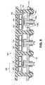
- FIG. 3 is a schematic axial section view of the ramjet of FIG. 2 including a fuel-cooled heat exchanger.
- FIG. 4A is an axial section view of a portion of the heat exchanger of FIG. 3 .
- FIG. 4B is a cross-sectional view of the heat exchanger taken along line 4B-4B of FIG. 4A .
- FIG. 5 is an axial section view of a portion of an alternative fuel-cooled heat exchanger.
- FIG. 6 is an axial section view of a portion of another alternative heat exchanger.
- FIG. 7 is an exploded perspective view of a portion of yet another alternative heat exchanger.
- FIG. 1 is a schematic view of vehicle 10 including fuselage 12, wing 14, tail assembly 16, engine 18, and cowl 20.
- Vehicle 10 may be, for example, a manned aircraft. Alternative vehicles may be unmanned and may be reusable or may be one-way vehicles (e.g., missiles or disposable launch vehicles). Although this description is made with reference to a vehicle, embodiments of the present invention are applicable to any platform that includes demanding thermal management and power generation needs.
- wing 14 and tail assembly 16 are supported by fuselage 12.
- Engine 18 is located in cowl 20 on an underside of fuselage 12.
- Air flow path 24 carries a flow 26 through engine 18 between a forward inlet/intake 28 and an aft outlet 30 (e.g., an exhaust nozzle).
- FIG. 2 is a schematic view of engine 18 located in cowl 20.
- Engine 18 includes gas turbine 32 and ramjet 34.
- An exemplary ramjet is a dual mode (i.e., subsonic and supersonic combustion) ramjet engine (i.e., a dual mode scramjet).
- a ramjet generally comprises a constricted tube through which inlet air is compressed by the high speed of the vehicle, a combustion chamber where fuel and compressed air are combusted, and a nozzle through which the exhaust jet leaves at higher speed than the inlet air, thereby generating thrust to power a vehicle in flight.
- There are few or no moving parts in a ramjet In particular, there is no highspeed turbine, as in a turbofan or turbojet engine, that is expensive to produce and maintain.
- a ramjet requires airflow through the engine (in a scramjet the airflow must be supersonic), and therefore has a minimum functional speed.
- turbine 32 may be used to power vehicle 10 up to an appropriate speed beyond which ramjet 34 may augment or replace turbine 32 to power vehicle 10.
- a portion 26a of air flow 26 can be directed along flow path 36 into turbine 32, while another portion 26b of flow 26 can be directed along flow path 38 into ramjet 34.
- Flow path 38 carries flow 26b through ramjet 34 between forward inlet/intake 28 and aft outlet 30.
- ramjet 34 may include a forebody 34a, an isolator 34b (often integrated therewith), and a combustor 34c.
- air is scooped into ramjet 34 through forebody 34a and compressed along isolator 34b before entering combustor 34c. The compressed air is mixed with fuel in combustor 34c and ignited.
- engine 18 may also include control system 40 configured to control operation of combustor 34c in response to one or more of sensor input, operator input, and the like. Control system 40 may optionally be included as a portion of the avionics of vehicle 10.
- Gas turbine 32 is located along air flow path 36 carrying flow 26a between a forward inlet/intake 42 and an aft outlet 44 inboard of ramjet flow path 26b (e.g., partially recessed into fuselage 12 above cowl 20).
- Ramjet and turbine inlet flaps 46 and 48 can selectively block ramjet and turbine inlets 28, 42 and flow paths 38, 36 when ramjet 34 or turbine 32, respectively, is not in operation.
- turbine outlet flap 50 may selectively block turbine flow path 36 when turbine 32 is not in use so as to provide an efficient nozzle for ramjet 34.
- FIG. 3 is a schematic axial section view showing further details of the ramjet engine 34 and flow 26b. At least a portion of flow 26b is largely surrounded by heat exchanger (or conduit assembly) 60 for transferring heat from the air and combustion gases in ramjet 34 to pre-combustion ramjet fuel.
- a radially inward face of heat exchanger (or HEX) 60 forms a gas flow conduit through which flow 26b of ramjet 34 passes.
- Heat exchanger 60 can be formed as a generally rectangular conduit surrounding flow 26b, sometimes referred to as a 2-D configuration, or as an annular conduit circumscribing flow 26b, sometimes referred to as a 3-D configuration.
- heat exchanger 60 is a liquid-fuel-cooled heat exchanger.
- An alternative fuel used to cool heat exchanger 60 is a hydrogen gas.
- Heat exchanger 60 can have an upstream fuel inlet 62 and a downstream fuel outlet 64. In the illustrated embodiment, the inlet 62 is upstream of combustor 34c along flow path 26b. Heat exchanger 60 can thereby be used to pre-heat the fuel used in combustor 34c using the hot air and fuel mixture exiting combustor 34c.
- Fuel flow 66 of ramjet 34 can extend from storage tank 68 to fuel pump 70 and then to inlet 62. After exiting outlet 64, heated fuel may pass along flow path 72 to a fuel distribution valve network 74 and then to combustor 34c.
- the valves of network 74 distribute the fuel to various combustor locations for various purposes (e.g., piloting v. main combustion) and to achieve desired staging.
- heat exchanger 60 thermoelectrically generates electricity. Accordingly, exchanger 60 can be coupled to an electrical power conditioning, storage, and distribution system, such as system 76 shown schematically in FIG. 3 .
- System 76 can receive raw electrical input from heat exchanger 60 and output appropriate electricity (e.g., of a constant and proper voltage) to drive, for example, control system 40, fuel pump 70, distribution valves of the network 74, similar components associated with turbine 32, and additional loads schematically shown as 78.
- FIGS. 4A and 4B are detail views of a portion of heat exchanger 60.
- FIG. 4A is an axial section view of a portion of heat exchanger 60 and
- FIG. 4B is a cross-sectional view of heat exchanger 60 taken along section line 4B-4B of FIG. 4A .
- Heat exchanger 60 includes gas flow conduit 80, one or more thermoelectric (TE) devices 82, one or more fuel cooled tubes 84, resilient members 86, support beams 88, truss 90, and casing 92.
- Thermal insulation 94 can optionally be provided adjacent to the fuel cooled tubes 84 opposite the TE devices 82.
- gas flow conduit 80 is configured to at least partially surround flow 26b and may be formed as a 2-D or 3-D type conduit.
- gas flow conduit 80 may be manufactured from, for example, high temperature alloys or ceramics, or a ceramic matrix composite (CMC), such as that described in U.S. Pat. No. 6,627,019 .
- CMC ceramic matrix composite
- a metal may tend to overheat because the TE devices 82 may act as a thermal insulator between the conduit 80 and the fuel-cooled tubes 84.
- CMC can typically operate at higher temperatures than metal, which makes it less likely to overheat in such applications.
- conduit 80 is arranged between flow 26b and TE devices 82, however the direction of flow 26b is shown merely for illustrative purposes and can vary as desired in alternative embodiments.
- Adjacent to (e.g., radially outward from) TE devices 82 are fuel cooled tubes 84.
- TE devices 82 are therefore arranged between the relatively hot gas flow conduit 80 and the relatively cool fuel cooled tubes 84, and can generate electricity from the thermal differential therebetween.
- the high heat flux into the hot gas flow conduit 80 from the hypersonic gas flow and combustion contributes to high levels of power being produced.
- fuel cooled tubes 84 are configured in sets of five generally rectangular tubes, the number, shape, and size of fuel cooled tubes used in heat exchanger 60 can vary as desired for particular applications.
- fuel cooled tubes 84 can be arranged in sets of three tubes having a generally circular cross-section, or sets of one tube having a generally rectangular cross-section (see, e.g., FIG. 6 ).
- TE devices produce a voltage in the presence of a temperature difference between two different electrically conductive materials.
- the voltage causes a continuous electrical current to flow in the conductors if they form a complete loop.
- the electrical current generated can be used to, for example, power accessory systems on an aircraft as discussed with reference to FIG. 3 above.
- TE devices generally function best with good thermal contact, and correspondingly good thermal conduction, between the TE device and, for example, a gas flow conduit of a fuel-cooled heat exchanger.
- manufacturing and assembly tolerances, variations in position and size in components during operation, and other factors may degrade contact between the TE device and the conduit.
- Embodiments of the present invention employ one or more resilient members 86 to bias the TE devices 82 into contact with both the relatively hot gas flow conduit 80 and the relatively cool fuel cooled tubes 84 between which the TE devices 82 are arranged.
- the biasing load placed on the TE devices 82 by the resilient members 86 can be selected to be sufficiently great to ensure contact, while remaining below the structural limits of the TE device 82.
- a functional range for TE devices 82 used in embodiments of the present invention is approximately 140 to 350 kPa (20 to 50 psi).
- a cross-sectional profile of gas flow conduit 80 is generally C-shaped, including first, second and third sides 80a, 80b, 80c, respectively, and an interrupted fourth side 80d.
- First side 80a includes a first face adjacent gas flow 26b and a second face in contact with TE devices 82.
- the second and third sides 80b and 80b both extend from the first side 80a, and are arranged opposite one another.
- the interrupted fourth side 80b includes portions that extend from the second and third sides 80b and 80c with a gap in between.
- heat exchanger 60 can include multiple TE devices 82, fuel cooled tubes 84, and resilient members 86 arranged in combination to substantially cover gas flow conduit 80.
- TE devices 82, fuel cooled tubes 84, and resilient members 86 are arranged at least partially within first, second, third, and fourth sides 80a, 80b, 80c, and 80d of gas flow conduit 80.
- TE devices 80 are arranged between gas flow conduit 80 and fuel cooled tubes 84.
- Fuel cooled tubes 84 are arranged between TE devices 82 and resilient members 86.
- Support beam 88 engages interrupted fourth side 84d of gas flow conduit 80 and can thereby compress resilient members 86 to bias the fuel cooled tubes 84 to help keep TE devices 82 in substantially continuous physical contact with fuel cooled tubes 84 and gas flow conduit 80.
- Resilient members 86 are corrugated thin plates of a resilient material, for example, spring steel. In alternative embodiments, the resilient members can be, for example, coil springs. Casing 92 and support beam 88 can be further supported by truss 90 arranged therebetween. Truss 90 has a corrugated configuration in the illustrated embodiment. Support beam 88 can be connected to truss 90 with beam clips 88a, for example, as shown in FIGS. 4A and 4B .
- FIG. 5 is an axial section view of a portion of an alternative heat exchanger 100 including gas flow conduit 102, TE devices 104, fuel cooled tubes 106, resilient members 108, backing plate 110, supports 112, pressure plates 114, preload fasteners 116, and attachment fasteners 118.
- gas flow conduit 102 at least partially surrounds gas flow path 26b, and can be formed as a 2-D or 3-D type conduit. It should be noted that the direction of the gas flow path 26b shown in FIG. 5 is shown merely by way of example, and can vary as desired for particular embodiments.
- gas flow conduit 102 can be manufactured from, for example, high temperature alloys or ceramics, or a CMC material, as discussed above with respect to a previous embodiment.
- Conduit 102 is arranged between gas flow path 26b and TE devices 104.
- Adjacent to (e.g., radially outward from) TE devices 104 are fuel cooled tubes 106.
- TE devices 104 are therefore arranged between the relatively hot gas flow conduit 102 and the relatively cool fuel cooled tubes 106, and can generate electricity from the thermal differential therebetween.
- Supports 112 extend between backing plate 110 and gas flow conduit 102.
- Backing plate 110 can be connected to supports 112 by attachment fasteners 118.
- Attachment fasteners 118 can be bolts, screws, rivets, or the like. Pressure plates 114 are arranged between resilient members 108 and TE devices 104. Preload fasteners 116 include lock nuts 116a and set screws 116b, and are configured to preload pressure plate 114 by compressing resilient members 108 relative to backing plate 110 and preload fasteners 116 to help keep TE devices 104 in substantially continuous physical contact with fuel cooled tubes 106 and gas flow conduit 102.
- Resilient members 108 can be, for example, coil springs or Belleville washers (i.e., disc springs).
- FIG. 6 is an axial section view of a portion of another alternative heat exchanger 130 including gas flow conduit 132, TE devices 134, fuel cooled tubes 136, resilient members 138, support plates 140, fasteners 142, truss 144, and casing 146.
- gas flow conduit 132 at least partially surrounds gas flow path 26b and can be formed as a 2-D or 3-D type conduit.
- Gas flow conduit 132 can be manufactured from, for example, high temperature alloys or ceramics, or a CMC material.
- Conduit 132 is arranged between gas flow path 26b and TE devices 134. Adjacent to (e.g., radially outward from) TE devices 134 are fuel cooled tubes 136.
- gas flow conduit 132 includes multiple adjacent C-shaped portions, each of which contains one TE device 134, one fuel cooled tube 136, and multiple resilient members 138.
- Resilient members 138 can be generally C-shaped springs (or other types of springs, such as leaf springs) arranged between portions (e.g., interrupted sides) of each C-shaped portion of gas flow conduit 132 and fuel cooled tubes 136, typically at opposite edges of each fuel cooled tube 136.
- Support plates 140 are attached to gas flow conduit 132 by fasteners 142.
- Fasteners 142 are configured to generate a load on support plates 140, which in turn transfers the load to the hook shaped portion of fasteners 142 that engages gas flow conduit 132.
- the load transferred to fasteners 142 acts to compress resilient members 138 against fuel cooled tubes 136 to help keep TE devices 134 in substantially continuous physical contact with fuel cooled tubes 136 and gas flow conduit 132.
- Casing 146 can be attached to support plates 140 and supported by truss 144 arranged between casing 146 and support plates 140.
- FIG. 7 is an exploded perspective view of a portion of yet another alternative heat exchanger 150 including gas flow conduit 152, TE devices 154, fuel cooled tubes 156, resilient members 158, support plate 160, fasteners 162, and support columns 164.
- gas flow conduit 152 at least partially surrounds gas flow path 26b and can be formed as a 2-D or 3-D type conduit.
- gas flow conduit 152 can be manufactured from, for example, high temperature alloys or ceramics, or a CMC material.
- Conduit 152 is arranged between gas flow path 26b and TE devices 154. Adjacent to (e.g., radially outward from) TE devices 154 are fuel cooled tubes 156.
- TE devices 154 are therefore arranged between the relatively hot gas flow conduit 152 and the relatively cool fuel cooled tubes 156.
- Fasteners 162 (shown in FIG. 7 to include a threaded shaft and nut) fix TE devices 154 and fuel cooled tubes 156 between gas flow conduit 152 and support plate 160.
- resilient members 158 Interposed between support plate 160 and fasteners 162 are resilient members 158, which may be, for example, coil springs or Belleville washers. Fasteners 162 are thereby configured to generate a preload that compresses resilient members 158 against support plate 160 to bring TE devices 154 into contact with fuel cooled tubes 156 and gas flow conduit 152.
- Support columns 164 can be employed to provide structural support between support plate 160 and, for example, a ramjet casing (not shown).
- Embodiments of the present invention employing TE devices enable many, if not all of a vehicle's secondary power requirements to be met by the heat exchanger with lighter weight and lower volume compared to both hydrazine auxiliary power unit (APU) and battery based systems.
- Embodiments of the present invention help increase thermal conduction of the TE device in a fuel-cooled heat exchanger by employing one or more resilient members to bias the TE device into substantially continuous physical contact with both (a) the hot gas flow conduit and (b) the cool fuel cooled tubes, between which the TE device is arranged.
- the load placed on the TE device by the resilient members, directly or indirectly, is sufficient to promote physical contact, while remaining below the structural limits of the TE device.
- Such contact can be maintained across extreme and/or varying thermal and mechanical conditions experienced during flight (e.g., differential thermal growth between the various components in both steady state and transient conditions).
- Increasing thermal conduction between the TE device and adjacent components helps increase the efficiency and magnitude of power generated by the TE device.
- Fuel-cooled heat exchangers according to the present invention therefore improve vehicle range compared to the more traditional approaches, such as the hydrazine APU based approach, because of enhanced electrical power generation capabilities.
- Performance testing of the present invention was carried out using a prototype having a similar configuration to heat exchanger 150 shown in FIG. 7 .
- the heat exchanger was tested in an atmospheric burner rig.
- the atmospheric burner rig testing demonstrated integration of a thermoelectric device into a ceramic matrix composite (CMC) fuel-cooled HEX structure under conditions relevant to a scramjet engine.
- CMC ceramic matrix composite
- a maximum power output of 13.4-16 watts with a Watt density of 2.4-2.8 W/cm 2 was achieved for the single stage lead telluride/tellurium-antimony-germanium-silver (PbTe/TAGS) device for thermal differentials ( ⁇ T) between 456- 514° C at hot face temperatures between 550-609° C for 3-4 minute run times.
- the heat exchanger was also successfully tested for 18 minutes with minimum power degradation and no effect on the CMC hot face (i.e. the face of the gas flow conduit surrounding the gas flow). The 18 minute test time is in excess of a typical 15 minute missile flight time.
- a power of 10 watts was achieved with the higher temperature differentials between 685-721° C at hot face temperatures between 765-790° C and two stage cascade TE devices with a silicon germanium upper stage and a lead telluride/tellurium-antimony-germanium-silver lower stage (SiGe//PbTe/TAGS) device.
- the heat exchanger performed as designed for a total accumulated test time of 107 minutes with hot-face temperatures up to 1100° C.
Abstract
Description
- Hypersonic vehicles hold potential for future military application by shortening the time-to-target and thereby extending global reach. These vehicles are anticipated to be powered by scramjet (supersonic combustion ramjet) engines during hypersonic flight conditions. The structure which forms the hypersonic flow path in a scramjet engine is referred to in the art as a heat exchanger (HEX), which is a reference to the dual use of the flow conduit structure as a heat exchanger. Hypersonic HEXs are commonly fuel-cooled because air-cooling is not practical in hypersonic flight conditions. Fuel cooling also serves to preheat the combustion fuel, thereby adding energy to the fuel for combustion. In conventional jet engines, fuel pumps, on-board electric systems, and other accessory systems parasitically draw power from the engine's main power plant to function. However, unlike conventional jet engines, scramjet engines have no rotating mechanical elements. Hypersonic vehicles are therefore currently envisioned to rely on auxiliary power units (APUs) and/or batteries to meet the vehicle power requirements. However, both APUs and battery systems add significant weight, volume and system complexity.
- An apparatus according to the present invention includes an inlet conduit assembly surrounding a gas flow path and a combustor arranged downstream of the inlet conduit assembly. The inlet conduit assembly includes a thermoelectric (TE) device configured to convert heat into electrical energy, a gas flow conduit arranged between the gas flow path and the TE device, and a resilient member configured to bias the TE device into contact with the gas flow conduit.
-
FIG. 1 is a schematic view of vehicle including hybrid gas turbine and ramjet engine. -
FIG. 2 is a schematic view of the hybrid gas turbine and ramjet engine ofFIG. 1 . -
FIG. 3 is a schematic axial section view of the ramjet ofFIG. 2 including a fuel-cooled heat exchanger. -
FIG. 4A is an axial section view of a portion of the heat exchanger ofFIG. 3 . -
FIG. 4B is a cross-sectional view of the heat exchanger taken alongline 4B-4B ofFIG. 4A . -
FIG. 5 is an axial section view of a portion of an alternative fuel-cooled heat exchanger. -
FIG. 6 is an axial section view of a portion of another alternative heat exchanger. -
FIG. 7 is an exploded perspective view of a portion of yet another alternative heat exchanger. -
FIG. 1 is a schematic view ofvehicle 10 includingfuselage 12,wing 14,tail assembly 16,engine 18, andcowl 20.Vehicle 10 may be, for example, a manned aircraft. Alternative vehicles may be unmanned and may be reusable or may be one-way vehicles (e.g., missiles or disposable launch vehicles). Although this description is made with reference to a vehicle, embodiments of the present invention are applicable to any platform that includes demanding thermal management and power generation needs. InFIG. 1 ,wing 14 andtail assembly 16 are supported byfuselage 12.Engine 18 is located incowl 20 on an underside offuselage 12.Air flow path 24 carries aflow 26 throughengine 18 between a forward inlet/intake 28 and an aft outlet 30 (e.g., an exhaust nozzle). -
FIG. 2 is a schematic view ofengine 18 located incowl 20.Engine 18 includesgas turbine 32 andramjet 34. An exemplary ramjet is a dual mode (i.e., subsonic and supersonic combustion) ramjet engine (i.e., a dual mode scramjet). A ramjet generally comprises a constricted tube through which inlet air is compressed by the high speed of the vehicle, a combustion chamber where fuel and compressed air are combusted, and a nozzle through which the exhaust jet leaves at higher speed than the inlet air, thereby generating thrust to power a vehicle in flight. There are few or no moving parts in a ramjet. In particular, there is no highspeed turbine, as in a turbofan or turbojet engine, that is expensive to produce and maintain. A ramjet requires airflow through the engine (in a scramjet the airflow must be supersonic), and therefore has a minimum functional speed. For example, in the hybrid vehicle shown inFIGS. 1-3 ,turbine 32 may be used to powervehicle 10 up to an appropriate speed beyond whichramjet 34 may augment or replaceturbine 32 topower vehicle 10. - In
FIG. 2 , aportion 26a ofair flow 26 can be directed alongflow path 36 intoturbine 32, while anotherportion 26b offlow 26 can be directed alongflow path 38 intoramjet 34.Flow path 38 carriesflow 26b throughramjet 34 between forward inlet/intake 28 andaft outlet 30. Alongflow path 38,ramjet 34 may include aforebody 34a, anisolator 34b (often integrated therewith), and acombustor 34c. During operation, air is scooped intoramjet 34 throughforebody 34a and compressed alongisolator 34b before enteringcombustor 34c. The compressed air is mixed with fuel incombustor 34c and ignited. The products of combustion are exhausted throughoutlet 30 to produce useful thrust used to powervehicle 10 in flight. As shown inFIG. 2 ,engine 18 may also includecontrol system 40 configured to control operation ofcombustor 34c in response to one or more of sensor input, operator input, and the like.Control system 40 may optionally be included as a portion of the avionics ofvehicle 10. -
Gas turbine 32 is located alongair flow path 36 carryingflow 26a between a forward inlet/intake 42 and anaft outlet 44 inboard oframjet flow path 26b (e.g., partially recessed intofuselage 12 above cowl 20). Ramjet andturbine inlet flaps turbine inlets flow paths ramjet 34 orturbine 32, respectively, is not in operation. Similarly,turbine outlet flap 50 may selectively blockturbine flow path 36 whenturbine 32 is not in use so as to provide an efficient nozzle forramjet 34. -
FIG. 3 is a schematic axial section view showing further details of theramjet engine 34 and flow 26b. At least a portion offlow 26b is largely surrounded by heat exchanger (or conduit assembly) 60 for transferring heat from the air and combustion gases inramjet 34 to pre-combustion ramjet fuel. A radially inward face of heat exchanger (or HEX) 60 forms a gas flow conduit through which flow 26b oframjet 34 passes.Heat exchanger 60 can be formed as a generally rectangularconduit surrounding flow 26b, sometimes referred to as a 2-D configuration, or as an annular conduitcircumscribing flow 26b, sometimes referred to as a 3-D configuration. For an exemplary hydrocarbon-based fuel,heat exchanger 60 is a liquid-fuel-cooled heat exchanger. An alternative fuel used to coolheat exchanger 60 is a hydrogen gas.Heat exchanger 60 can have anupstream fuel inlet 62 and adownstream fuel outlet 64. In the illustrated embodiment, theinlet 62 is upstream ofcombustor 34c alongflow path 26b.Heat exchanger 60 can thereby be used to pre-heat the fuel used incombustor 34c using the hot air and fuelmixture exiting combustor 34c.Fuel flow 66 oframjet 34 can extend fromstorage tank 68 tofuel pump 70 and then to inlet 62. After exitingoutlet 64, heated fuel may pass along flow path 72 to a fueldistribution valve network 74 and then tocombustor 34c. The valves ofnetwork 74 distribute the fuel to various combustor locations for various purposes (e.g., piloting v. main combustion) and to achieve desired staging. - In addition to pre-heating combustion fuel,
heat exchanger 60 thermoelectrically generates electricity. Accordingly,exchanger 60 can be coupled to an electrical power conditioning, storage, and distribution system, such assystem 76 shown schematically inFIG. 3 .System 76 can receive raw electrical input fromheat exchanger 60 and output appropriate electricity (e.g., of a constant and proper voltage) to drive, for example,control system 40,fuel pump 70, distribution valves of thenetwork 74, similar components associated withturbine 32, and additional loads schematically shown as 78. -
FIGS. 4A and 4B are detail views of a portion ofheat exchanger 60.FIG. 4A is an axial section view of a portion ofheat exchanger 60 andFIG. 4B is a cross-sectional view ofheat exchanger 60 taken alongsection line 4B-4B ofFIG. 4A .Heat exchanger 60 includesgas flow conduit 80, one or more thermoelectric (TE)devices 82, one or more fuel cooledtubes 84,resilient members 86, support beams 88,truss 90, andcasing 92.Thermal insulation 94 can optionally be provided adjacent to the fuel cooledtubes 84 opposite theTE devices 82. InFIGS. 4A and 4B ,gas flow conduit 80 is configured to at least partially surroundflow 26b and may be formed as a 2-D or 3-D type conduit. In order to withstand the extreme operating temperatures of hypersonic flight,gas flow conduit 80 may be manufactured from, for example, high temperature alloys or ceramics, or a ceramic matrix composite (CMC), such as that described inU.S. Pat. No. 6,627,019 . CMC is approximately one third the density of metal and therefore provides significant weight savings over a metal conduit. In some applications, a metal may tend to overheat because theTE devices 82 may act as a thermal insulator between theconduit 80 and the fuel-cooledtubes 84. CMC can typically operate at higher temperatures than metal, which makes it less likely to overheat in such applications. In the illustrated embodiment,conduit 80 is arranged betweenflow 26b andTE devices 82, however the direction offlow 26b is shown merely for illustrative purposes and can vary as desired in alternative embodiments. Adjacent to (e.g., radially outward from)TE devices 82 are fuel cooledtubes 84.TE devices 82 are therefore arranged between the relatively hotgas flow conduit 80 and the relatively cool fuel cooledtubes 84, and can generate electricity from the thermal differential therebetween. The high heat flux into the hotgas flow conduit 80 from the hypersonic gas flow and combustion contributes to high levels of power being produced. Although in the illustrated embodiment fuel cooledtubes 84 are configured in sets of five generally rectangular tubes, the number, shape, and size of fuel cooled tubes used inheat exchanger 60 can vary as desired for particular applications. For example, fuel cooledtubes 84 can be arranged in sets of three tubes having a generally circular cross-section, or sets of one tube having a generally rectangular cross-section (see, e.g.,FIG. 6 ). - Generally speaking, known TE devices produce a voltage in the presence of a temperature difference between two different electrically conductive materials. The voltage causes a continuous electrical current to flow in the conductors if they form a complete loop. The electrical current generated can be used to, for example, power accessory systems on an aircraft as discussed with reference to
FIG. 3 above. TE devices generally function best with good thermal contact, and correspondingly good thermal conduction, between the TE device and, for example, a gas flow conduit of a fuel-cooled heat exchanger. However, manufacturing and assembly tolerances, variations in position and size in components during operation, and other factors may degrade contact between the TE device and the conduit. Embodiments of the present invention employ one or moreresilient members 86 to bias theTE devices 82 into contact with both the relatively hotgas flow conduit 80 and the relatively cool fuel cooledtubes 84 between which theTE devices 82 are arranged. The biasing load placed on theTE devices 82 by theresilient members 86, directly or indirectly, can be selected to be sufficiently great to ensure contact, while remaining below the structural limits of theTE device 82. For example, a functional range forTE devices 82 used in embodiments of the present invention is approximately 140 to 350 kPa (20 to 50 psi). - In
FIG. 4A , a cross-sectional profile ofgas flow conduit 80 is generally C-shaped, including first, second andthird sides fourth side 80d.First side 80a includes a first faceadjacent gas flow 26b and a second face in contact withTE devices 82. The second andthird sides first side 80a, and are arranged opposite one another. The interruptedfourth side 80b includes portions that extend from the second andthird sides - As illustrated in
FIGS. 4A and 4B ,heat exchanger 60 can includemultiple TE devices 82, fuel cooledtubes 84, andresilient members 86 arranged in combination to substantially covergas flow conduit 80. In the portion of heat exchanger illustrated inFIG. 4A ,TE devices 82, fuel cooledtubes 84, andresilient members 86 are arranged at least partially within first, second, third, andfourth sides gas flow conduit 80.TE devices 80 are arranged betweengas flow conduit 80 and fuel cooledtubes 84. Fuel cooledtubes 84 are arranged betweenTE devices 82 andresilient members 86.Support beam 88 engages interrupted fourth side 84d ofgas flow conduit 80 and can thereby compressresilient members 86 to bias the fuel cooledtubes 84 to help keepTE devices 82 in substantially continuous physical contact with fuel cooledtubes 84 andgas flow conduit 80. -
Resilient members 86 are corrugated thin plates of a resilient material, for example, spring steel. In alternative embodiments, the resilient members can be, for example, coil springs.Casing 92 andsupport beam 88 can be further supported bytruss 90 arranged therebetween.Truss 90 has a corrugated configuration in the illustrated embodiment.Support beam 88 can be connected totruss 90 withbeam clips 88a, for example, as shown inFIGS. 4A and 4B . -
FIG. 5 is an axial section view of a portion of analternative heat exchanger 100 includinggas flow conduit 102,TE devices 104, fuel cooledtubes 106,resilient members 108, backingplate 110, supports 112, pressure plates 114, preload fasteners 116, andattachment fasteners 118. InFIG. 5 ,gas flow conduit 102 at least partially surroundsgas flow path 26b, and can be formed as a 2-D or 3-D type conduit. It should be noted that the direction of thegas flow path 26b shown inFIG. 5 is shown merely by way of example, and can vary as desired for particular embodiments. In order to withstand the extreme operating temperatures of hypersonic flight,gas flow conduit 102 can be manufactured from, for example, high temperature alloys or ceramics, or a CMC material, as discussed above with respect to a previous embodiment.Conduit 102 is arranged betweengas flow path 26b andTE devices 104. Adjacent to (e.g., radially outward from)TE devices 104 are fuel cooledtubes 106.TE devices 104 are therefore arranged between the relatively hotgas flow conduit 102 and the relatively cool fuel cooledtubes 106, and can generate electricity from the thermal differential therebetween.Supports 112 extend betweenbacking plate 110 andgas flow conduit 102. Backingplate 110 can be connected tosupports 112 byattachment fasteners 118.Attachment fasteners 118 can be bolts, screws, rivets, or the like. Pressure plates 114 are arranged betweenresilient members 108 andTE devices 104. Preload fasteners 116 include lock nuts 116a and setscrews 116b, and are configured to preload pressure plate 114 by compressingresilient members 108 relative tobacking plate 110 and preload fasteners 116 to help keepTE devices 104 in substantially continuous physical contact with fuel cooledtubes 106 andgas flow conduit 102.Resilient members 108 can be, for example, coil springs or Belleville washers (i.e., disc springs). -
FIG. 6 is an axial section view of a portion of anotheralternative heat exchanger 130 includinggas flow conduit 132,TE devices 134, fuel cooledtubes 136,resilient members 138,support plates 140,fasteners 142,truss 144, andcasing 146. InFIG. 6 ,gas flow conduit 132 at least partially surroundsgas flow path 26b and can be formed as a 2-D or 3-D type conduit.Gas flow conduit 132 can be manufactured from, for example, high temperature alloys or ceramics, or a CMC material.Conduit 132 is arranged betweengas flow path 26b andTE devices 134. Adjacent to (e.g., radially outward from)TE devices 134 are fuel cooledtubes 136.TE devices 134 are therefore arranged between the relatively hotgas flow conduit 132 and the relatively cool fuel cooledtubes 136, and can generate electricity from the thermal differential therebetween. In the illustrated embodiment,gas flow conduit 132 includes multiple adjacent C-shaped portions, each of which contains oneTE device 134, one fuel cooledtube 136, and multipleresilient members 138.Resilient members 138 can be generally C-shaped springs (or other types of springs, such as leaf springs) arranged between portions (e.g., interrupted sides) of each C-shaped portion ofgas flow conduit 132 and fuel cooledtubes 136, typically at opposite edges of each fuel cooledtube 136.Support plates 140 are attached togas flow conduit 132 byfasteners 142.Fasteners 142 are configured to generate a load onsupport plates 140, which in turn transfers the load to the hook shaped portion offasteners 142 that engagesgas flow conduit 132. The load transferred tofasteners 142 acts to compressresilient members 138 against fuel cooledtubes 136 to help keepTE devices 134 in substantially continuous physical contact with fuel cooledtubes 136 andgas flow conduit 132. Casing 146 can be attached to supportplates 140 and supported bytruss 144 arranged betweencasing 146 andsupport plates 140. -
FIG. 7 is an exploded perspective view of a portion of yet anotheralternative heat exchanger 150 includinggas flow conduit 152,TE devices 154, fuel cooledtubes 156,resilient members 158,support plate 160,fasteners 162, and supportcolumns 164. InFIG. 7 ,gas flow conduit 152 at least partially surroundsgas flow path 26b and can be formed as a 2-D or 3-D type conduit. In order to withstand the extreme operating temperatures of hypersonic flight,gas flow conduit 152 can be manufactured from, for example, high temperature alloys or ceramics, or a CMC material.Conduit 152 is arranged betweengas flow path 26b andTE devices 154. Adjacent to (e.g., radially outward from)TE devices 154 are fuel cooledtubes 156.TE devices 154 are therefore arranged between the relatively hotgas flow conduit 152 and the relatively cool fuel cooledtubes 156. Fasteners 162 (shown inFIG. 7 to include a threaded shaft and nut)fix TE devices 154 and fuel cooledtubes 156 betweengas flow conduit 152 andsupport plate 160. Interposed betweensupport plate 160 andfasteners 162 areresilient members 158, which may be, for example, coil springs or Belleville washers.Fasteners 162 are thereby configured to generate a preload that compressesresilient members 158 againstsupport plate 160 to bringTE devices 154 into contact with fuel cooledtubes 156 andgas flow conduit 152.Support columns 164 can be employed to provide structural support betweensupport plate 160 and, for example, a ramjet casing (not shown). - Embodiments of the present invention employing TE devices enable many, if not all of a vehicle's secondary power requirements to be met by the heat exchanger with lighter weight and lower volume compared to both hydrazine auxiliary power unit (APU) and battery based systems. Embodiments of the present invention help increase thermal conduction of the TE device in a fuel-cooled heat exchanger by employing one or more resilient members to bias the TE device into substantially continuous physical contact with both (a) the hot gas flow conduit and (b) the cool fuel cooled tubes, between which the TE device is arranged. The load placed on the TE device by the resilient members, directly or indirectly, is sufficient to promote physical contact, while remaining below the structural limits of the TE device. Such contact can be maintained across extreme and/or varying thermal and mechanical conditions experienced during flight (e.g., differential thermal growth between the various components in both steady state and transient conditions). Increasing thermal conduction between the TE device and adjacent components helps increase the efficiency and magnitude of power generated by the TE device. Fuel-cooled heat exchangers according to the present invention therefore improve vehicle range compared to the more traditional approaches, such as the hydrazine APU based approach, because of enhanced electrical power generation capabilities.
- Performance testing of the present invention was carried out using a prototype having a similar configuration to
heat exchanger 150 shown inFIG. 7 . The heat exchanger was tested in an atmospheric burner rig. The atmospheric burner rig testing demonstrated integration of a thermoelectric device into a ceramic matrix composite (CMC) fuel-cooled HEX structure under conditions relevant to a scramjet engine. The following two TE devices fabricated by Research Triangle Institute (RTI) of Research Triangle Park, North Carolina were tested in the heat exchanger under temperature conditions present in an isolator section of a scramjet flowpath: 1) single stage lead telluride/tellurium-antimony-germanium-silver (PbTe/TAGS) and 2) two stage cascade with silicon germanium upper stage and lead telluride/tellurium-antimony-germanium-silver lower stage (SiGe//PbTe/TAGS). A maximum power output of 13.4-16 watts with a Watt density of 2.4-2.8 W/cm2 was achieved for the single stage lead telluride/tellurium-antimony-germanium-silver (PbTe/TAGS) device for thermal differentials (ΔT) between 456- 514° C at hot face temperatures between 550-609° C for 3-4 minute run times. The heat exchanger was also successfully tested for 18 minutes with minimum power degradation and no effect on the CMC hot face (i.e. the face of the gas flow conduit surrounding the gas flow). The 18 minute test time is in excess of a typical 15 minute missile flight time. In another test, a power of 10 watts was achieved with the higher temperature differentials between 685-721° C at hot face temperatures between 765-790° C and two stage cascade TE devices with a silicon germanium upper stage and a lead telluride/tellurium-antimony-germanium-silver lower stage (SiGe//PbTe/TAGS) device. The heat exchanger performed as designed for a total accumulated test time of 107 minutes with hot-face temperatures up to 1100° C. - While the invention has been described with reference to an exemplary embodiment(s), it will be understood by those skilled in the art that various changes may be made and equivalents may be substituted for elements thereof without departing from the scope of the invention, which is defined by the appended claims. For example, the present invention can be utilized with a variety of types of engines for electrical power generation.
Claims (15)
- An apparatus comprising:an inlet conduit assembly surrounding a gas flow path (26b), the inlet conduit assembly comprising:a thermoelectric (TE) device (82) configured to convert heat into electrical energy;a gas flow conduit (80) arranged between the gas flow path and the TE device; anda resilient member (86) configured to bias the TE device into contact with the gas flow conduit; anda combustor (34c) arranged downstream of the inlet conduit assembly.
- The apparatus of claim 1, wherein the inlet conduit assembly further comprises:a tube (84) configured to be cooled by a fuel, wherein the TE device is arranged between the gas flow conduit and the fuel-cooled tube.
- The apparatus of claim 2, wherein the fuel-cooled tube (84) is arranged between the TE device and the resilient member.
- The apparatus of claim 1, 2 or 3,
wherein at least a portion of the gas flow conduit has a generally C-shape comprising uninterrupted first (80a), second (80b) and third (80c) sides, and an interrupted fourth side (80d), the first side comprising a first face adjacent the gas flow path and a second face in contact with the TE device; and
wherein the TE device and the resilient member are arranged within the first, second, third, and fourth sides. - The apparatus of claim 4, wherein the inlet conduit assembly further comprises a support member (88) configured to engage the interrupted fourth side of the gas flow conduit and compress the resilient member (86) to apply a load on the TE device.
- The apparatus of claim 4 or 5, wherein the interrupted fourth side (80d) comprises:a first portion extending generally perpendicular to the second side;a second portion extending generally perpendicular to the third side toward the first portion; anda gap between the first and second portions defining the interruption in the fourth side;wherein the resilient member (86) comprises one or more resilient members arranged in compression between the first and second portions of the fourth side and the TE device.
- The apparatus of claim 4, 5 or 6, further comprising a member interposed between the one or more resilient members and the TE device, the member comprising one or more of a support plate, a support beam, and a tube configured to be cooled by a fuel.
- The apparatus of claim 4, 5, 6 or 7 wherein the TE device comprises a plurality of TE devices and the resilient member comprises one or more resilient members.
- The apparatus of claim 8, wherein the gas flow conduit comprises:a plurality of adjacent C-shaped portions each of which is configured to contain at least one of the TE devices and at least one of the resilient members.
- The apparatus of claim 8, wherein the gas flow conduit comprises:a single C-shaped portion configured to contain the plurality of TE devices and the one or more resilient members.
- The apparatus of any preceding claim, further comprising:a backing plate;two or more supports extending between the backing plate and the gas flow conduit;a pressure plate arranged between the resilient member and the TE device; anda fastener configured to compress the resilient member against the pressure plate;wherein the resilient member is arranged between the backing plate and the pressure plate.
- The apparatus of claim 11, wherein the TE device comprises a plurality of TE devices and the resilient member comprises one or more resilient members, and the apparatus comprises:more than two supports extending between the backing plate and the gas flow conduit;wherein at least one TE device and at least one resilient member is arranged between every pair of two supports.
- The apparatus of any preceding claim, wherein the gas flow conduit comprises a ceramic matrix composite.
- The apparatus of any preceding claim, wherein the gas flow conduit comprises one of a generally rectangular or annular shape in a direction substantially perpendicular to the gas flow path, wherein the resilient member is configured to apply a load on the TE device of approximately 140 to 350 kPa (20 to 50 psi).
- A vehicle (10) comprising:a fuselage (12); anda ramjet (18) connected to the fuselage and having an apparatus as claimed in any preceding claim, the inlet conduit assembly forming a fuel-cooled heat exchanger (60) surrounding a gas flow path of the ramjet.
Applications Claiming Priority (2)
| Application Number | Priority Date | Filing Date | Title |
|---|---|---|---|
| US21100909P | 2009-03-25 | 2009-03-25 | |
| US12/550,150 US8522560B2 (en) | 2009-03-25 | 2009-08-28 | Fuel-cooled heat exchanger with thermoelectric device compression |
Publications (3)
| Publication Number | Publication Date |
|---|---|
| EP2233728A2 true EP2233728A2 (en) | 2010-09-29 |
| EP2233728A3 EP2233728A3 (en) | 2014-03-05 |
| EP2233728B1 EP2233728B1 (en) | 2018-09-05 |
Family
ID=42200053
Family Applications (1)
| Application Number | Title | Priority Date | Filing Date |
|---|---|---|---|
| EP10250567.4A Active EP2233728B1 (en) | 2009-03-25 | 2010-03-25 | Fuel-cooled heat exchanger with thermoelectric device compression |
Country Status (2)
| Country | Link |
|---|---|
| US (1) | US8522560B2 (en) |
| EP (1) | EP2233728B1 (en) |
Cited By (1)
| Publication number | Priority date | Publication date | Assignee | Title |
|---|---|---|---|---|
| CN114313253A (en) * | 2022-03-03 | 2022-04-12 | 中国空气动力研究与发展中心计算空气动力研究所 | Aerodynamic layout and design method of high lift-drag ratio air-breathing hypersonic aircraft |
Families Citing this family (15)
| Publication number | Priority date | Publication date | Assignee | Title |
|---|---|---|---|---|
| DE102011016917A1 (en) * | 2011-04-13 | 2012-10-18 | Rolls-Royce Deutschland Ltd & Co Kg | Gas turbine combustor with a holder of a seal for an attachment |
| WO2014144535A1 (en) * | 2013-03-15 | 2014-09-18 | Mtpv Power Corporation | Microchannel heat sink for micro-gap thermophotovoltaic device |
| US9651258B2 (en) | 2013-03-15 | 2017-05-16 | Rolls-Royce Corporation | Shell and tiled liner arrangement for a combustor |
| US10538013B2 (en) * | 2014-05-08 | 2020-01-21 | United Technologies Corporation | Integral ceramic matrix composite fastener with non-polymer rigidization |
| US10371011B2 (en) * | 2014-05-08 | 2019-08-06 | United Technologies Corporation | Integral ceramic matrix composite fastener with polymer rigidization |
| DE112016002619T5 (en) | 2015-06-10 | 2018-04-05 | Gentherm Inc. | A vehicle battery thermoelectric device having an integrated cold plate assembly and methods of mounting the same |
| US20180166621A1 (en) * | 2015-06-10 | 2018-06-14 | Gentherm Inc. | Vehicle battery thermoelectric device with integrated cold plate assembly |
| CN106184742A (en) * | 2016-09-18 | 2016-12-07 | 厦门大学 | A kind of supersonic vehicle air intake duct microchannel cooling system |
| US10655853B2 (en) | 2016-11-10 | 2020-05-19 | United Technologies Corporation | Combustor liner panel with non-linear circumferential edge for a gas turbine engine combustor |
| US10830433B2 (en) | 2016-11-10 | 2020-11-10 | Raytheon Technologies Corporation | Axial non-linear interface for combustor liner panels in a gas turbine combustor |
| US10935236B2 (en) | 2016-11-10 | 2021-03-02 | Raytheon Technologies Corporation | Non-planar combustor liner panel for a gas turbine engine combustor |
| US10935235B2 (en) | 2016-11-10 | 2021-03-02 | Raytheon Technologies Corporation | Non-planar combustor liner panel for a gas turbine engine combustor |
| US10590848B2 (en) * | 2017-06-06 | 2020-03-17 | Raytheon Company | Flight vehicle air breathing propulsion system with isolator having obstruction |
| JP6975658B2 (en) * | 2018-02-23 | 2021-12-01 | 三菱重工業株式会社 | Rectifying structure and flying object |
| US20220252012A1 (en) * | 2021-02-11 | 2022-08-11 | General Electric Company | Flowpath assembly with composite tube array |
Citations (1)
| Publication number | Priority date | Publication date | Assignee | Title |
|---|---|---|---|---|
| US6627019B2 (en) | 2000-12-18 | 2003-09-30 | David C. Jarmon | Process for making ceramic matrix composite parts with cooling channels |
Family Cites Families (36)
| Publication number | Priority date | Publication date | Assignee | Title |
|---|---|---|---|---|
| US2990775A (en) * | 1958-02-24 | 1961-07-04 | Henson West | Cooling system based on thermoelectric principles |
| US3733826A (en) * | 1964-02-10 | 1973-05-22 | Texaco Experiment Inc | Fuel cooled ram air reaction propulsion engine |
| US4037751A (en) * | 1973-04-18 | 1977-07-26 | Summa Corporation | Insulation system |
| US4065936A (en) * | 1976-06-16 | 1978-01-03 | Borg-Warner Corporation | Counter-flow thermoelectric heat pump with discrete sections |
| US4372211A (en) * | 1980-04-14 | 1983-02-08 | The United States Of America As Represented By The Secretary Of The Army | Thermoelectric power supply for warheads |
| US4580524A (en) * | 1984-09-07 | 1986-04-08 | The United States Of America As Represented By The United States Department Of Energy | Process for the preparation of fiber-reinforced ceramic composites by chemical vapor deposition |
| US5135184A (en) * | 1990-08-22 | 1992-08-04 | The Johns Hopkins University | Propellant utilization system |
| US5337975A (en) * | 1992-02-28 | 1994-08-16 | Rockwell International Corporation | Breathing system for hypersonic aircraft |
| US5892656A (en) | 1993-10-19 | 1999-04-06 | Bass; John C. | Thermoelectric generator |
| US5584183A (en) * | 1994-02-18 | 1996-12-17 | Solid State Cooling Systems | Thermoelectric heat exchanger |
| US5874775A (en) * | 1994-08-03 | 1999-02-23 | Sumitomo Electric Industries, Ltd. | Diamond heat sink including microchannel therein and methods for manufacturing diamond heat sinks |
| DE19746229B4 (en) * | 1996-10-18 | 2019-08-01 | Nikon Corp. | Progressive multifocal lens |
| US6300150B1 (en) * | 1997-03-31 | 2001-10-09 | Research Triangle Institute | Thin-film thermoelectric device and fabrication method of same |
| US6042315A (en) * | 1997-10-06 | 2000-03-28 | United Technologies Corporation | Fastener |
| US6045310A (en) * | 1997-10-06 | 2000-04-04 | United Technologies Corporation | Composite fastener for use in high temperature environments |
| US6345507B1 (en) * | 2000-09-29 | 2002-02-12 | Electrografics International Corporation | Compact thermoelectric cooling system |
| KR100452909B1 (en) | 2001-12-29 | 2004-10-14 | 한국동서발전(주) | Apparatus for generating thermoelectric semiconductor using of exhaust gas heat |
| KR20030064292A (en) * | 2002-01-25 | 2003-07-31 | 가부시키가이샤 고마쓰 세이사쿠쇼 | Thermoelectric module |
| US6907920B2 (en) * | 2002-01-29 | 2005-06-21 | United Technologies Corporation | Heat exchanger panel |
| KR100455924B1 (en) * | 2002-01-31 | 2004-11-06 | 삼성전자주식회사 | Cooling and Heating Apparatus Utlizing Thermoelectric Module |
| FR2836698B1 (en) * | 2002-03-04 | 2005-02-11 | Eads Launch Vehicles | COMBUSTION CHAMBER FOR STATOREACTOR AND STATOREACTOR PROVIDED WITH SUCH A COMBUSTION CHAMBER |
| US20030234008A1 (en) * | 2002-06-20 | 2003-12-25 | John Van Winkle | Dual cooling intake system for an internal combustion engine |
| US20040045594A1 (en) * | 2002-09-10 | 2004-03-11 | Enhanced Energy Systems, Inc. | Turbine engine with thermoelectric waste heat recovery system |
| US7210653B2 (en) * | 2002-10-22 | 2007-05-01 | The Boeing Company | Electric-based secondary power system architectures for aircraft |
| JP3722439B2 (en) | 2002-11-06 | 2005-11-30 | 川重冷熱工業株式会社 | Hybrid thermoelectric supply system |
| ES2287436T3 (en) * | 2002-11-13 | 2007-12-16 | Coprecitec, S.L. | THERMOELECTRIC GENERATOR GROUP WITH A PILOT BURNER. |
| US20060101822A1 (en) * | 2002-12-26 | 2006-05-18 | Kiyohito Murata | Exhaust heat power generation apparatus |
| US6834831B2 (en) * | 2002-12-31 | 2004-12-28 | The Boeing Company | Hybrid solid oxide fuel cell aircraft auxiliary power unit |
| US20050022855A1 (en) * | 2003-07-30 | 2005-02-03 | Raver Bernard J. | Thermoelectric power generator for a gas turbine engine |
| US20060063522A1 (en) * | 2004-09-21 | 2006-03-23 | Mcfarland Norman R | Self-powering automated building control components |
| US7254953B2 (en) * | 2005-01-06 | 2007-08-14 | Caterpillar Inc | Thermoelectric heat exchange element |
| US7963100B2 (en) * | 2005-05-25 | 2011-06-21 | Alliant Techsystems Inc. | Cooling system for high-speed vehicles and method of cooling high-speed vehicles |
| US8313056B2 (en) | 2005-07-19 | 2012-11-20 | United Technologies Corporation | Engine heat exchanger with thermoelectric generation |
| US7385503B1 (en) * | 2006-08-03 | 2008-06-10 | Rosemount, Inc. | Self powered son device network |
| US8378205B2 (en) * | 2006-09-29 | 2013-02-19 | United Technologies Corporation | Thermoelectric heat exchanger |
| US8453456B2 (en) * | 2009-03-25 | 2013-06-04 | United Technologies Corporation | Fuel-cooled flexible heat exchanger with thermoelectric device compression |
-
2009
- 2009-08-28 US US12/550,150 patent/US8522560B2/en active Active
-
2010
- 2010-03-25 EP EP10250567.4A patent/EP2233728B1/en active Active
Patent Citations (1)
| Publication number | Priority date | Publication date | Assignee | Title |
|---|---|---|---|---|
| US6627019B2 (en) | 2000-12-18 | 2003-09-30 | David C. Jarmon | Process for making ceramic matrix composite parts with cooling channels |
Cited By (1)
| Publication number | Priority date | Publication date | Assignee | Title |
|---|---|---|---|---|
| CN114313253A (en) * | 2022-03-03 | 2022-04-12 | 中国空气动力研究与发展中心计算空气动力研究所 | Aerodynamic layout and design method of high lift-drag ratio air-breathing hypersonic aircraft |
Also Published As
| Publication number | Publication date |
|---|---|
| EP2233728B1 (en) | 2018-09-05 |
| EP2233728A3 (en) | 2014-03-05 |
| US8522560B2 (en) | 2013-09-03 |
| US20100242486A1 (en) | 2010-09-30 |
Similar Documents
| Publication | Publication Date | Title |
|---|---|---|
| EP2233728B1 (en) | Fuel-cooled heat exchanger with thermoelectric device compression | |
| US8453456B2 (en) | Fuel-cooled flexible heat exchanger with thermoelectric device compression | |
| US10533481B2 (en) | Thermal electric assembly attached on an outer surface of a hot section of a gas turbine engine to generate electrical power | |
| US8127555B2 (en) | Flowpath heat exchanger for thermal management and power generation within a hypersonic vehicle | |
| US9388740B2 (en) | Thermoelectric generator in turbine engine nozzles | |
| US8434292B2 (en) | Ceramic-encased hot surface igniter system for jet engines | |
| McDonald et al. | Recuperated gas turbine aeroengines, part II: engine design studies following early development testing | |
| Cirigliano et al. | Diesel, spark-ignition, and turboprop engines for long-duration unmanned air flights | |
| US11661889B1 (en) | Hydrogen powered geared turbo fan engine with an off-set reduced core | |
| CN103061856A (en) | Thermal electrical power generation for aircraft | |
| EP3055544A1 (en) | Combined turbojet and turboprop engine | |
| JP2003523298A (en) | Thermoelectric generator for aircraft | |
| US11015509B2 (en) | Systems and apparatus to generate electrical power from aircraft engine heat | |
| US11665963B1 (en) | Waste heat capture using tail cone of a gas turbine engine | |
| Patel et al. | Thermal Management and Power Generation for Directed Energy Weapons | |
| CN114576013B (en) | Turbine cooling method for aircraft engine | |
| EP4303418A1 (en) | Hybrid electric power for turbine engines having hydrogen fuel systems | |
| Jojic | Study of Innovative Subsonic Ramjet | |
| Regev et al. | Hybrid Jet Engine for Unmanned Aerial Systems (UAS) Applications | |
| Saetmark et al. | Secondary power system study for the Hytex RA3 flight test vehicle | |
| ALLEN | Analysis of booster systems with a recoverable hypersonic airplane first stage |
Legal Events
| Date | Code | Title | Description |
|---|---|---|---|
| PUAI | Public reference made under article 153(3) epc to a published international application that has entered the european phase |
Free format text: ORIGINAL CODE: 0009012 |
|
| AK | Designated contracting states |
Kind code of ref document: A2 Designated state(s): AT BE BG CH CY CZ DE DK EE ES FI FR GB GR HR HU IE IS IT LI LT LU LV MC MK MT NL NO PL PT RO SE SI SK SM TR |
|
| AX | Request for extension of the european patent |
Extension state: AL BA ME RS |
|
| PUAL | Search report despatched |
Free format text: ORIGINAL CODE: 0009013 |
|
| AK | Designated contracting states |
Kind code of ref document: A3 Designated state(s): AT BE BG CH CY CZ DE DK EE ES FI FR GB GR HR HU IE IS IT LI LT LU LV MC MK MT NL NO PL PT RO SE SI SK SM TR |
|
| AX | Request for extension of the european patent |
Extension state: AL BA ME RS |
|
| RIC1 | Information provided on ipc code assigned before grant |
Ipc: B64C 30/00 20060101ALI20140130BHEP Ipc: F02K 7/10 20060101AFI20140130BHEP Ipc: H01L 35/30 20060101ALI20140130BHEP Ipc: F02K 1/82 20060101ALI20140130BHEP Ipc: B64C 1/38 20060101ALI20140130BHEP Ipc: F02C 7/224 20060101ALI20140130BHEP Ipc: F01D 25/08 20060101ALI20140130BHEP |
|
| 17P | Request for examination filed |
Effective date: 20140828 |
|
| RBV | Designated contracting states (corrected) |
Designated state(s): AT BE BG CH CY CZ DE DK EE ES FI FR GB GR HR HU IE IS IT LI LT LU LV MC MK MT NL NO PL PT RO SE SI SK SM TR |
|
| RAP1 | Party data changed (applicant data changed or rights of an application transferred) |
Owner name: UNITED TECHNOLOGIES CORPORATION |
|
| STAA | Information on the status of an ep patent application or granted ep patent |
Free format text: STATUS: EXAMINATION IS IN PROGRESS |
|
| 17Q | First examination report despatched |
Effective date: 20170509 |
|
| GRAP | Despatch of communication of intention to grant a patent |
Free format text: ORIGINAL CODE: EPIDOSNIGR1 |
|
| STAA | Information on the status of an ep patent application or granted ep patent |
Free format text: STATUS: GRANT OF PATENT IS INTENDED |
|
| INTG | Intention to grant announced |
Effective date: 20180315 |
|
| GRAS | Grant fee paid |
Free format text: ORIGINAL CODE: EPIDOSNIGR3 |
|
| GRAA | (expected) grant |
Free format text: ORIGINAL CODE: 0009210 |
|
| STAA | Information on the status of an ep patent application or granted ep patent |
Free format text: STATUS: THE PATENT HAS BEEN GRANTED |
|
| AK | Designated contracting states |
Kind code of ref document: B1 Designated state(s): AT BE BG CH CY CZ DE DK EE ES FI FR GB GR HR HU IE IS IT LI LT LU LV MC MK MT NL NO PL PT RO SE SI SK SM TR |
|
| REG | Reference to a national code |
Ref country code: GB Ref legal event code: FG4D |
|
| REG | Reference to a national code |
Ref country code: CH Ref legal event code: EP |
|
| REG | Reference to a national code |
Ref country code: AT Ref legal event code: REF Ref document number: 1038096 Country of ref document: AT Kind code of ref document: T Effective date: 20180915 |
|
| REG | Reference to a national code |
Ref country code: IE Ref legal event code: FG4D |
|
| REG | Reference to a national code |
Ref country code: DE Ref legal event code: R096 Ref document number: 602010053282 Country of ref document: DE |
|
| REG | Reference to a national code |
Ref country code: NL Ref legal event code: MP Effective date: 20180905 |
|
| REG | Reference to a national code |
Ref country code: LT Ref legal event code: MG4D |
|
| PG25 | Lapsed in a contracting state [announced via postgrant information from national office to epo] |
Ref country code: SE Free format text: LAPSE BECAUSE OF FAILURE TO SUBMIT A TRANSLATION OF THE DESCRIPTION OR TO PAY THE FEE WITHIN THE PRESCRIBED TIME-LIMIT Effective date: 20180905 Ref country code: NO Free format text: LAPSE BECAUSE OF FAILURE TO SUBMIT A TRANSLATION OF THE DESCRIPTION OR TO PAY THE FEE WITHIN THE PRESCRIBED TIME-LIMIT Effective date: 20181205 Ref country code: FI Free format text: LAPSE BECAUSE OF FAILURE TO SUBMIT A TRANSLATION OF THE DESCRIPTION OR TO PAY THE FEE WITHIN THE PRESCRIBED TIME-LIMIT Effective date: 20180905 Ref country code: GR Free format text: LAPSE BECAUSE OF FAILURE TO SUBMIT A TRANSLATION OF THE DESCRIPTION OR TO PAY THE FEE WITHIN THE PRESCRIBED TIME-LIMIT Effective date: 20181206 Ref country code: BG Free format text: LAPSE BECAUSE OF FAILURE TO SUBMIT A TRANSLATION OF THE DESCRIPTION OR TO PAY THE FEE WITHIN THE PRESCRIBED TIME-LIMIT Effective date: 20181205 Ref country code: LT Free format text: LAPSE BECAUSE OF FAILURE TO SUBMIT A TRANSLATION OF THE DESCRIPTION OR TO PAY THE FEE WITHIN THE PRESCRIBED TIME-LIMIT Effective date: 20180905 |
|
| REG | Reference to a national code |
Ref country code: AT Ref legal event code: MK05 Ref document number: 1038096 Country of ref document: AT Kind code of ref document: T Effective date: 20180905 |
|
| PG25 | Lapsed in a contracting state [announced via postgrant information from national office to epo] |
Ref country code: ES Free format text: LAPSE BECAUSE OF FAILURE TO SUBMIT A TRANSLATION OF THE DESCRIPTION OR TO PAY THE FEE WITHIN THE PRESCRIBED TIME-LIMIT Effective date: 20180905 Ref country code: LV Free format text: LAPSE BECAUSE OF FAILURE TO SUBMIT A TRANSLATION OF THE DESCRIPTION OR TO PAY THE FEE WITHIN THE PRESCRIBED TIME-LIMIT Effective date: 20180905 Ref country code: HR Free format text: LAPSE BECAUSE OF FAILURE TO SUBMIT A TRANSLATION OF THE DESCRIPTION OR TO PAY THE FEE WITHIN THE PRESCRIBED TIME-LIMIT Effective date: 20180905 |
|
| PG25 | Lapsed in a contracting state [announced via postgrant information from national office to epo] |
Ref country code: NL Free format text: LAPSE BECAUSE OF FAILURE TO SUBMIT A TRANSLATION OF THE DESCRIPTION OR TO PAY THE FEE WITHIN THE PRESCRIBED TIME-LIMIT Effective date: 20180905 Ref country code: PL Free format text: LAPSE BECAUSE OF FAILURE TO SUBMIT A TRANSLATION OF THE DESCRIPTION OR TO PAY THE FEE WITHIN THE PRESCRIBED TIME-LIMIT Effective date: 20180905 Ref country code: EE Free format text: LAPSE BECAUSE OF FAILURE TO SUBMIT A TRANSLATION OF THE DESCRIPTION OR TO PAY THE FEE WITHIN THE PRESCRIBED TIME-LIMIT Effective date: 20180905 Ref country code: AT Free format text: LAPSE BECAUSE OF FAILURE TO SUBMIT A TRANSLATION OF THE DESCRIPTION OR TO PAY THE FEE WITHIN THE PRESCRIBED TIME-LIMIT Effective date: 20180905 Ref country code: IS Free format text: LAPSE BECAUSE OF FAILURE TO SUBMIT A TRANSLATION OF THE DESCRIPTION OR TO PAY THE FEE WITHIN THE PRESCRIBED TIME-LIMIT Effective date: 20190105 Ref country code: CZ Free format text: LAPSE BECAUSE OF FAILURE TO SUBMIT A TRANSLATION OF THE DESCRIPTION OR TO PAY THE FEE WITHIN THE PRESCRIBED TIME-LIMIT Effective date: 20180905 Ref country code: RO Free format text: LAPSE BECAUSE OF FAILURE TO SUBMIT A TRANSLATION OF THE DESCRIPTION OR TO PAY THE FEE WITHIN THE PRESCRIBED TIME-LIMIT Effective date: 20180905 Ref country code: IT Free format text: LAPSE BECAUSE OF FAILURE TO SUBMIT A TRANSLATION OF THE DESCRIPTION OR TO PAY THE FEE WITHIN THE PRESCRIBED TIME-LIMIT Effective date: 20180905 |
|
| PG25 | Lapsed in a contracting state [announced via postgrant information from national office to epo] |
Ref country code: PT Free format text: LAPSE BECAUSE OF FAILURE TO SUBMIT A TRANSLATION OF THE DESCRIPTION OR TO PAY THE FEE WITHIN THE PRESCRIBED TIME-LIMIT Effective date: 20190105 Ref country code: SM Free format text: LAPSE BECAUSE OF FAILURE TO SUBMIT A TRANSLATION OF THE DESCRIPTION OR TO PAY THE FEE WITHIN THE PRESCRIBED TIME-LIMIT Effective date: 20180905 Ref country code: SK Free format text: LAPSE BECAUSE OF FAILURE TO SUBMIT A TRANSLATION OF THE DESCRIPTION OR TO PAY THE FEE WITHIN THE PRESCRIBED TIME-LIMIT Effective date: 20180905 |
|
| REG | Reference to a national code |
Ref country code: DE Ref legal event code: R097 Ref document number: 602010053282 Country of ref document: DE |
|
| PLBE | No opposition filed within time limit |
Free format text: ORIGINAL CODE: 0009261 |
|
| STAA | Information on the status of an ep patent application or granted ep patent |
Free format text: STATUS: NO OPPOSITION FILED WITHIN TIME LIMIT |
|
| PG25 | Lapsed in a contracting state [announced via postgrant information from national office to epo] |
Ref country code: DK Free format text: LAPSE BECAUSE OF FAILURE TO SUBMIT A TRANSLATION OF THE DESCRIPTION OR TO PAY THE FEE WITHIN THE PRESCRIBED TIME-LIMIT Effective date: 20180905 |
|
| 26N | No opposition filed |
Effective date: 20190606 |
|
| PG25 | Lapsed in a contracting state [announced via postgrant information from national office to epo] |
Ref country code: SI Free format text: LAPSE BECAUSE OF FAILURE TO SUBMIT A TRANSLATION OF THE DESCRIPTION OR TO PAY THE FEE WITHIN THE PRESCRIBED TIME-LIMIT Effective date: 20180905 |
|
| PG25 | Lapsed in a contracting state [announced via postgrant information from national office to epo] |
Ref country code: MC Free format text: LAPSE BECAUSE OF FAILURE TO SUBMIT A TRANSLATION OF THE DESCRIPTION OR TO PAY THE FEE WITHIN THE PRESCRIBED TIME-LIMIT Effective date: 20180905 |
|
| REG | Reference to a national code |
Ref country code: CH Ref legal event code: PL |
|
| PG25 | Lapsed in a contracting state [announced via postgrant information from national office to epo] |
Ref country code: LU Free format text: LAPSE BECAUSE OF NON-PAYMENT OF DUE FEES Effective date: 20190325 |
|
| REG | Reference to a national code |
Ref country code: BE Ref legal event code: MM Effective date: 20190331 |
|
| PG25 | Lapsed in a contracting state [announced via postgrant information from national office to epo] |
Ref country code: IE Free format text: LAPSE BECAUSE OF NON-PAYMENT OF DUE FEES Effective date: 20190325 Ref country code: LI Free format text: LAPSE BECAUSE OF NON-PAYMENT OF DUE FEES Effective date: 20190331 Ref country code: CH Free format text: LAPSE BECAUSE OF NON-PAYMENT OF DUE FEES Effective date: 20190331 |
|
| PG25 | Lapsed in a contracting state [announced via postgrant information from national office to epo] |
Ref country code: BE Free format text: LAPSE BECAUSE OF NON-PAYMENT OF DUE FEES Effective date: 20190331 |
|
| PG25 | Lapsed in a contracting state [announced via postgrant information from national office to epo] |
Ref country code: TR Free format text: LAPSE BECAUSE OF FAILURE TO SUBMIT A TRANSLATION OF THE DESCRIPTION OR TO PAY THE FEE WITHIN THE PRESCRIBED TIME-LIMIT Effective date: 20180905 |
|
| PG25 | Lapsed in a contracting state [announced via postgrant information from national office to epo] |
Ref country code: MT Free format text: LAPSE BECAUSE OF NON-PAYMENT OF DUE FEES Effective date: 20190325 |
|
| PG25 | Lapsed in a contracting state [announced via postgrant information from national office to epo] |
Ref country code: CY Free format text: LAPSE BECAUSE OF FAILURE TO SUBMIT A TRANSLATION OF THE DESCRIPTION OR TO PAY THE FEE WITHIN THE PRESCRIBED TIME-LIMIT Effective date: 20180905 |
|
| PG25 | Lapsed in a contracting state [announced via postgrant information from national office to epo] |
Ref country code: HU Free format text: LAPSE BECAUSE OF FAILURE TO SUBMIT A TRANSLATION OF THE DESCRIPTION OR TO PAY THE FEE WITHIN THE PRESCRIBED TIME-LIMIT; INVALID AB INITIO Effective date: 20100325 |
|
| PG25 | Lapsed in a contracting state [announced via postgrant information from national office to epo] |
Ref country code: MK Free format text: LAPSE BECAUSE OF FAILURE TO SUBMIT A TRANSLATION OF THE DESCRIPTION OR TO PAY THE FEE WITHIN THE PRESCRIBED TIME-LIMIT Effective date: 20180905 |
|
| REG | Reference to a national code |
Ref country code: DE Ref legal event code: R081 Ref document number: 602010053282 Country of ref document: DE Owner name: RAYTHEON TECHNOLOGIES CORPORATION (N.D.GES.D.S, US Free format text: FORMER OWNER: UNITED TECHNOLOGIES CORPORATION, FARMINGTON, CONN., US |
|
| PGFP | Annual fee paid to national office [announced via postgrant information from national office to epo] |
Ref country code: FR Payment date: 20230222 Year of fee payment: 14 |
|
| PGFP | Annual fee paid to national office [announced via postgrant information from national office to epo] |
Ref country code: GB Payment date: 20230222 Year of fee payment: 14 Ref country code: DE Payment date: 20230221 Year of fee payment: 14 |
|
| P01 | Opt-out of the competence of the unified patent court (upc) registered |
Effective date: 20230519 |