EP2242006A2 - Portable data carrier - Google Patents
Portable data carrier Download PDFInfo
- Publication number
- EP2242006A2 EP2242006A2 EP10007364A EP10007364A EP2242006A2 EP 2242006 A2 EP2242006 A2 EP 2242006A2 EP 10007364 A EP10007364 A EP 10007364A EP 10007364 A EP10007364 A EP 10007364A EP 2242006 A2 EP2242006 A2 EP 2242006A2
- Authority
- EP
- European Patent Office
- Prior art keywords
- data carrier
- portable data
- light
- user
- contactless communication
- Prior art date
- Legal status (The legal status is an assumption and is not a legal conclusion. Google has not performed a legal analysis and makes no representation as to the accuracy of the status listed.)
- Granted
Links
Images

Classifications
-
- H—ELECTRICITY
- H01—ELECTRIC ELEMENTS
- H01Q—ANTENNAS, i.e. RADIO AERIALS
- H01Q1/00—Details of, or arrangements associated with, antennas
- H01Q1/12—Supports; Mounting means
- H01Q1/22—Supports; Mounting means by structural association with other equipment or articles
- H01Q1/2208—Supports; Mounting means by structural association with other equipment or articles associated with components used in interrogation type services, i.e. in systems for information exchange between an interrogator/reader and a tag/transponder, e.g. in Radio Frequency Identification [RFID] systems
-
- G—PHYSICS
- G06—COMPUTING; CALCULATING OR COUNTING
- G06K—GRAPHICAL DATA READING; PRESENTATION OF DATA; RECORD CARRIERS; HANDLING RECORD CARRIERS
- G06K19/00—Record carriers for use with machines and with at least a part designed to carry digital markings
- G06K19/06—Record carriers for use with machines and with at least a part designed to carry digital markings characterised by the kind of the digital marking, e.g. shape, nature, code
- G06K19/067—Record carriers with conductive marks, printed circuits or semiconductor circuit elements, e.g. credit or identity cards also with resonating or responding marks without active components
- G06K19/07—Record carriers with conductive marks, printed circuits or semiconductor circuit elements, e.g. credit or identity cards also with resonating or responding marks without active components with integrated circuit chips
- G06K19/077—Constructional details, e.g. mounting of circuits in the carrier
- G06K19/07749—Constructional details, e.g. mounting of circuits in the carrier the record carrier being capable of non-contact communication, e.g. constructional details of the antenna of a non-contact smart card
-
- H—ELECTRICITY
- H01—ELECTRIC ELEMENTS
- H01Q—ANTENNAS, i.e. RADIO AERIALS
- H01Q1/00—Details of, or arrangements associated with, antennas
- H01Q1/12—Supports; Mounting means
- H01Q1/22—Supports; Mounting means by structural association with other equipment or articles
- H01Q1/2208—Supports; Mounting means by structural association with other equipment or articles associated with components used in interrogation type services, i.e. in systems for information exchange between an interrogator/reader and a tag/transponder, e.g. in Radio Frequency Identification [RFID] systems
- H01Q1/2225—Supports; Mounting means by structural association with other equipment or articles associated with components used in interrogation type services, i.e. in systems for information exchange between an interrogator/reader and a tag/transponder, e.g. in Radio Frequency Identification [RFID] systems used in active tags, i.e. provided with its own power source or in passive tags, i.e. deriving power from RF signal
Definitions
- the present invention relates to a portable data carrier adapted for contactless data exchange with the aid of an electromagnetic alternating field.
- US 5,874,724 A1 or US2004 / 0012496A1 detects a light sensor on an RFID tag incoming light and accordingly releases a contactless communication; so that the release, for example, only occurs when the RFID tag is exposed to daylight or is exposed to light.
- a light sensor is combined with a switch such that the state of the switch affects whether or how much light hits the light sensor.
- This approach provides a reliable sharing option. Compared to a conceivable solution with logical AND connection of two independent signals from a light sensor and a switching element, the evaluation is simplified according to the invention.
- the switch is formed by a thermochromic layer.
- Inventive means for maintaining the release allow the contactless communication for a suitable period, for example, the maximum expected transaction time.
- the light sensor includes a photoconductive element and a photosensitive element.
- the photoconductive element conducts the incoming light to the photosensitive element, so that a relative arrangement of the components can be made flexible.
- the light sensor is formed by a photovoltaic element, since thus the release can take place independently or temporally before the presence of a required for the communication electromagnetic alternating field.
- means for indicating a release state for the user are provided.
- the release state becomes recognizable to the user regardless of the state of the switch.
- the switch is designed as an irreversibly switchable element, for example in the form of an irreversibly removable element, it can be used for first-time use detection.
- the present invention can be applied to the following forms of portable data carriers: smart cards, mass storage cards, USB sticks, identification documents such as passports, which are preferably book-shaped, documents of value or banknotes.
- Fig.1 shows a functional cross-sectional view of a portable data carrier 1, which includes a processor 2 and an antenna 3 as contactless communication means.
- a light sensor 4 generates an enable signal 5, which indicates to the processor 2 that contactless communication may be performed.
- thermochromic layer 6 Towards the outside of the portable data carrier 1, there is a thermochromic layer 6 above the light sensor 4.
- the thermochromic layer 6 is intransparent in its ground state for light having a first wavelength.
- it can represent a first optical information perceptible to the user, for example the color "red", a stop sign or an icon for an opened switch.
- the user can change the light transmittance of the thermochromic layer 6 at least for the first frequency by manual heating of the thermochromic layer, in particular by placing a finger or by rubbing.
- the change of the light passing through the thermochromic layer 6 to the light sensor 4 is detected.
- the subsequently generated enable signal 5 notifies the processor 2 not only that light has been detected, but also that the user has deliberately operated a switch to allow contactless communication.
- the thermochromic layer 6 In the second, heated state, the thermochromic layer 6 also provides the user with altered optical information, such as the color green, an hourglass, or a closed switch symbol.
- the optical information thus indicates to the user a switching state of the thermochromic layer 6 (as a switch).
- it may be adapted to indicate to the user that and / or where by interaction Communication of the portable data carrier 1 can release.
- thermochromic layer means for maintaining the release.
- the maintaining means are in particular adapted to maintain the release irrespective of the presence of a communication field and / or for a suitable period of time.
- the appropriate period of time can be selected as the maximum expected communication duration, optionally plus an expected time until a communication field is present or the portable data carrier is led by the user into this field.
- Maintenance means may be provided in the contactless communication means, for example by storing the release as information and monitoring a timer (time counter). After the expiry of the timer, the release information is deleted, thus terminating the communication readiness. The timer may optionally be restarted by predetermined communication events. If a communication has been started before the expiration of the timer, the communication or corresponding transaction is also completed. The release is insofar a release for receiving a contactless communication.
- the switch can also serve as a maintenance means. If the switch is switchable between two permanent states (0 or 1), no further maintenance means are necessary.
- the thermochromic layer 6 can usually maintain its switching state only for too short a time, therefore additional maintenance means should be provided.
- a phosphorescent Substance be contained in the light sensor or at another suitable location. Suitable locations are, for example, a layer adjoining the light sensor or a transparent intermediate layer, not shown, which is arranged between the light sensor 4 and the thermochromic layer 6.
- the light sensor 4 may be configured as a photovoltaic element.
- This form of a sensor is not only inexpensive, but also easily integrated into the structure of the portable data carrier.
- the photovoltaic element makes it possible to provide maintenance means just for bridging the otherwise critical period of time in which there is still no communication field which also supplies the portable data carrier 1 with the energy required for operating the processor 2.
- the enable signal of the photovoltaic element can apply the energy necessary for the storage of the release information.
- a capacitor as a maintenance means is a simple element and also well adjustable in terms of temporal behavior. The capacitor is charged by the enable signal. A minimum charge state of the capacitor is evaluated by the processor 2 as stored, positive release information. The characteristics or arrangement of the capacitor are chosen so that it discharges to the minimum state of charge until the expiration of the appropriate period above.
- the light sensor 4 preferably detects the daylight and / or the artificial light of a room lighting.
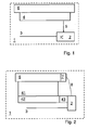
- Fig. 2 shows, also as a functional cross-sectional view, another variant of a portable data carrier according to the invention 1.
- the illustrated portable data carrier 1 contains a heating element 7 which is supplied with energy via a supply line 8 from the contactless communication means 2, 3.
- the light sensor comprises an optional transparent region 41, a light-conducting and / or collecting region 42 and the actual sensor as photosensitive element 43.
- the light-sensitive element 43 may be integrated in the processor 2.
- thermochromic layer is transmissive and the light is passed over the transparent region and light guide 42 to the photosensitive element 43, which then generates the enable signal.
- the heating element 7 can serve as a maintenance means. Via the optional connecting line 8, the heating element 7 receives energy, which is preferably taken from the communication field. It heats the thermochromic layer 6 and thus maintains the enable signal. Alternatively or additionally, the energy for the heating element 7 can also originate from an energy store, such as a battery, of the portable data carrier 1. If, as already described, the thermochromic layer also contains optical information for the user, the optical information can thus also be maintained at the same time.
- the heating element is preferably arranged as a transparent intermediate layer between the thermochromic layer 6 and the light sensor.
- the antenna and the light sensor are arranged in the same plane, wherein the plane is parallel to the thermochromic layer.
- the antenna 3 for example provided together with the light sensor and optionally also the processor on a carrier substrate as an inlay for the production of the data carrier.
- the switch is repeatedly switchable.
- the following are in particular with reference to Fig. 3 described further embodiments in which the switch is irreversibly switchable.
- the user receives his portable data carrier and can release it for use by the irreversible switching process. This allows the user initial recognition.
- Fig. 3 shows a removably disposed on the outside of the portable data carrier 1 switching element 60.
- the switching element 60 is at least for a wavelength of daylight intransparent, for example, it is colored black or red.
- the further construction of the portable data carrier 1 with light sensor 4, enable signal 5, antenna 3 and processor 2 corresponds to the structure according to FIG. 1 ,
- the light sensor 4 is adapted to generate the enable signal when it detects from the incoming light that the switching element 60 has been removed from the portable data carrier.
- the switching element 60 may be configured, for example, as a scratch-off or removable sticker.
- the irreversibly removable element or the portable data carrier should be equipped with a tamper detection protection, which makes a manipulation attempt by removing and re-attaching the user recognizable.
- the removable element (on its back side) or the portable data carrier in the area on which the removable element is applied may be provided with a light- and / or oxygen-sensitive element.
- the element Upon removal of the switching element 60, the element responds to the oxygen or light with an irreversible color change.
- the color changes only so fast that the user can perceive the change well. That is, the change should not be so slow that it does not attract the user, nor so fast that the user can not recognize it.
- the in FIG. 1 shown switch can be used as irreversible switch.
- the thermochromic layer 6 could be adapted to allow a color change in response to heat only once.
- this layer could respond to pressure as user interaction with an irreversibly altered translucency.
- the change could be caused in the layer by a chemical reaction, for example by the mixing of two components after a breakup of microcapsules or by pressing two adjacent, corresponding sublayers.
Abstract
Description
Die vorliegende Erfindung betrifft einen tragbaren Datenträger eingerichtet für den kontaktlosen Datenaustausch mit Hilfe eines elektromagnetischen Wechselfeldes.The present invention relates to a portable data carrier adapted for contactless data exchange with the aid of an electromagnetic alternating field.
Für kontaktlose tragbare Datenträger ist es ein häufig thematisiertes Problem, dass der Datenträger nicht ohne Zustimmung des Benutzers Daten mit einem entsprechenden Lesegerät austauschen sollte.For contactless portable data carriers, it is a frequently discussed problem that the data carrier should not exchange data with a corresponding reader without the consent of the user.
Als eine Lösung ist es beispielsweise aus
Ein weiterer, beispielsweise in
Gemäß
Es ist die Aufgabe der vorliegenden Erfindung, eine alternative Lösung zur Verhinderung einer unerwünschten kontaktlosen Kommunikation bereitzustellen.It is the object of the present invention to provide an alternative solution for preventing unwanted contactless communication.
Diese Aufgabe wird gelöst durch den Gegenstand der unabhängigen Ansprüche. Bevorzugte Ausführungsformen sind durch die abhängigen Ansprüche angegeben.This object is solved by the subject matter of the independent claims. Preferred embodiments are indicated by the dependent claims.
Gemäß der vorliegenden Erfindung wird ein Lichtsensor so mit einem Schalter kombiniert, dass der Zustand des Schalters beeinflusst, ob oder wieviel Licht auf den Lichtsensor trifft. Dieser Ansatz bietet eine zuverlässige Freigabemöglichkeit. Gegenüber einer denkbaren Lösung mit logischer UND-Verknüpfung zweier unabhängiger Signale von einem Lichtsensor und einem Schaltelement, ist die Auswertung erfindungsgemäß vereinfacht.According to the present invention, a light sensor is combined with a switch such that the state of the switch affects whether or how much light hits the light sensor. This approach provides a reliable sharing option. Compared to a conceivable solution with logical AND connection of two independent signals from a light sensor and a switching element, the evaluation is simplified according to the invention.
In einer bevorzugten Ausgestaltung, die kostengünstig herzustellen ist, wird der Schalter durch eine thermochrome Schicht gebildet.In a preferred embodiment, which is inexpensive to manufacture, the switch is formed by a thermochromic layer.
Erfindungsgemäße Mittel zur Aufrechterhaltung der Freigabe ermöglichen die kontaktlose Kommunikation für einen geeigneten Zeitraum, beispielsweise der maximalen zu erwartenden Transaktionszeit.Inventive means for maintaining the release allow the contactless communication for a suitable period, for example, the maximum expected transaction time.
In weiteren Ausgestaltungen enthält der Lichtsensor ein lichtleitendes Element und ein lichtempfindliches Element. Das lichtleitende Element leitet das eintreffende Licht zum lichtempfindlichen Element, so dass eine relative Anordnung der Komponenten flexibel gestaltet werden kann.In further embodiments, the light sensor includes a photoconductive element and a photosensitive element. The photoconductive element conducts the incoming light to the photosensitive element, so that a relative arrangement of the components can be made flexible.
Es ist besonders vorteilhaft, wenn der Lichtsensor durch ein photovoltaisches Element gebildet wird, da somit die Freigabe unabhängig bzw. zeitlich vor dem Vorliegen eines für die Kommunikation nötigen elektromagnetischen Wechselfelds erfolgen kann.It is particularly advantageous if the light sensor is formed by a photovoltaic element, since thus the release can take place independently or temporally before the presence of a required for the communication electromagnetic alternating field.
In bevorzugten Ausgestaltungen sind Mittel zur Anzeige eines Freigabezustandes für den Benutzer vorgesehen. Insbesondere wenn diese Mittel nicht durch den Schalter selbst bereitgestellt werden, wird der Freigabezustand unabhängig vom Zustand des Schalters für den Benutzer erkennbar.In preferred embodiments, means for indicating a release state for the user are provided. In particular, when these means are not provided by the switch itself, the release state becomes recognizable to the user regardless of the state of the switch.
Gestaltet man den Schalter als irreversibel schaltbares Element aus, beispielsweise in der Form eines irreversibel entfernbaren Elements, kann er zur Erstbenutzungserkennung verwendet werden.If the switch is designed as an irreversibly switchable element, for example in the form of an irreversibly removable element, it can be used for first-time use detection.
Die vorliegende Erfindung kann beispielsweise angewendet werden in folgenden Formen von tragbaren Datenträgern: Chipkarten, Massenspeicherkarten, USB-Sticks, Ausweisdokumenten, wie beispielsweise Reispässen, die vorzugsweise buchförmig gestaltet sind, Wertdokumenten oder Banknoten.For example, the present invention can be applied to the following forms of portable data carriers: smart cards, mass storage cards, USB sticks, identification documents such as passports, which are preferably book-shaped, documents of value or banknotes.
Im Folgenden werden bevorzugte Ausführungsformen der Erfindung mit Bezug auf die Figuren beschrieben. Die Figuren zeigen im Einzelnen:
- Fig.1
- eine erste Ausführungsform eines erfindungsgemäßen, tragbaren Datenträgers mit einer über einem Freigabesensor angeordneten thermochromen Schicht;
- Fig. 2
- eine zweite Ausführungsform eines erfindungsgemäßen, tragbaren Datenträgers mit einer thermochromen Schicht und einem Lichtsen- sor; und
- Fig. 3
- eine dritte Ausführungsform eines erfindungsgemäßen, tragbaren Datenträgers mit einem irreversibel entfernbaren Element über ei- nem Lichtsensor.
- Fig.1
- a first embodiment of a portable data carrier according to the invention with a disposed over a release sensor thermochromic layer;
- Fig. 2
- a second embodiment of a portable data carrier according to the invention with a thermochromic layer and a light sensor; and
- Fig. 3
- a third embodiment of a portable data carrier according to the invention with an irreversibly removable element via a light sensor.
Zur Außenseite des tragbaren Datenträgers 1 hin, liegt eine thermochrome Schicht 6 über dem Lichtsensor 4. Die thermochrome Schicht 6, ist in ihrem Grundzustand für Licht mit einer ersten Wellenlänge intransparent. Zudem kann sie in dem Grundzustand eine für den Benutzer wahrnehmbare erste optische Information, beispielsweise die Farbe "rot", ein Stoppschild oder eine Symbol für einen geöffneten Schalter, darstellen.Towards the outside of the
Der Benutzer kann durch manuelle Erwärmung der thermochromen Schicht, insbesondere durch Auflegen eines Fingers oder durch Reiben, die Lichtdurchlässigkeit der thermochromen Schicht 6 zumindest für die erste Frequenz ändern. Die Änderung des durch die thermochrome Schicht 6 zu dem Lichtsensor 4 gelangenden Lichts wird detektiert. Das daraufhin erzeugte Freigabesignal 5 teilt dem Prozessor 2 nicht nur mit, dass Licht erkannt wurde, sondern auch dass der Benutzer bewusst einen Schalter betätigt hat, um eine kontaktlose Kommunikation zuzulassen.The user can change the light transmittance of the
In dem zweiten, erwärmten Zustand stellt die thermochrome Schicht 6 auch dem Benutzer eine geänderte optische Information dar, beispielsweise die Farbe grün, eine Sanduhr oder ein Symbol für einen geschlossenen Schalter. Die optische Information zeigt dem Benutzer also einen Schaltzustand der thermochromen Schicht 6 (als Schalter) an. Zudem kann sie angepaßt sein, dem Benutzer anzuzeigen dass und / oder wo er durch Interaktion eine Kommunikation des tragbaren Datenträgers 1 freigeben kann.In the second, heated state, the
Damit die kontaktlose Kommunikation nicht nur solange möglich ist, wie der Benutzer die thermochrome Schicht beeinflusst, können Mittel zur Aufrechterhaltung der Freigabe vorgesehen werden. Die Aufrechterhaltungsmittel sind insbesondere angepasst, die Freigabe aufrecht zu erhalten unabhängig von einem Vorliegen eines Kommunikationsfeldes und / oder für eine geeigneten Zeitraum. Der geeignete Zeitraum kann gewählt werden als maximale zu erwartende Kommunikationsdauer, optional zuzüglich einer zu erwartenden Zeit bis ein Kommunikationsfeld vorliegt bzw. der tragbare Datenträger vom Benutzer in dieses Feld geführt wird.So that the contactless communication is not only possible as long as the user influences the thermochromic layer, means for maintaining the release can be provided. The maintaining means are in particular adapted to maintain the release irrespective of the presence of a communication field and / or for a suitable period of time. The appropriate period of time can be selected as the maximum expected communication duration, optionally plus an expected time until a communication field is present or the portable data carrier is led by the user into this field.
Aufrechterhaltungsmittel können in den Kontaktloskommunikationsmitteln bereitgestellt werden, beispielsweise durch Speichern der Freigabe als Information und Überwachen eines Timers (Zeitzähler). Nach dem Ablauf des Timers wird die Freigabeinformation gelöscht und somit die Kommunikationsbereitschaft beendet. Der Timer kann optional durch vorbestimmte Kommunikationsereignisse erneut gestartet werden. Sollte vor dem Ablauf des Timers eine Kommunikation begonnen worden sein, wird die Kommunikation bzw. entsprechende Transaktion auch abgeschlossen. Die Freigabe ist insofern eine Freigabe zum Aufnehmen einer kontaktlosen Kommunikation.Maintenance means may be provided in the contactless communication means, for example by storing the release as information and monitoring a timer (time counter). After the expiry of the timer, the release information is deleted, thus terminating the communication readiness. The timer may optionally be restarted by predetermined communication events. If a communication has been started before the expiration of the timer, the communication or corresponding transaction is also completed. The release is insofar a release for receiving a contactless communication.
Abhängig von der Ausgestaltung des Schalters kann auch der Schalter als Aufrechterhaltungsmittel dienen. Ist der Schalter zwischen zwei dauerhaften Zuständen schaltbar (0 oder 1), sind keine weiteren Aufrechterhaltungsmittel nötig. Die thermochrome Schicht 6 kann ihren Schaltzustand in der Regel nur für eine zu kurze Zeit aufrechterhalten, daher sollten zusätzliche Aufrechterhaltungsmittel vorgesehen werden. Beispielsweise kann eine phosphoreszierende Substanz in dem Lichtsensor oder an einer anderen geeigneten Stelle enthalten sein. Geeignete Stellen sind beispielsweise eine an den Lichtsensor angrenzende Schicht oder eine nicht dargestellte transparente Zwischenschicht, die zwischen dem Lichtsensor 4 und der thermochromen Schicht 6 angeordnet ist.Depending on the design of the switch, the switch can also serve as a maintenance means. If the switch is switchable between two permanent states (0 or 1), no further maintenance means are necessary. The
Der Lichtsensor 4 kann als photovoltaisches Element ausgestaltet sein. Diese Form eines Sensors ist nicht nur kostengünstig, sondern auch leicht in den Aufbau des tragbaren Datenträgers integrierbar. Zudem ermöglicht das photovoltaische Element, Aufrechterhaltungsmittel gerade zur Überbrückung des ansonsten kritischen Zeitraums bereit zu stellen, in dem noch kein Kommunikationsfeld vorliegt, welches den tragbaren Datenträger 1 auch mit der zum Betrieb des Prozessors 2 nötigen Energie versorgt. Beispielsweise kann das Freigabesignal des photovoltaischen Elements die zur Speicherung der Freigabeinformation nötige Energie aufbringen. Ein Kondensator als Aufrechterhaltungsmittel ist ein einfaches Element und zudem bezüglich des zeitlichen Verhaltens gut einstellbar. Der Kondensator wird vom Freigabesignal geladen. Ein minimaler Ladungszustand des Kondensators wird vom Prozessor 2 als gespeicherte, positive Freigabeinformation gewertet. Die Eigenschaften oder die Anordnung des Kondensators werden so gewählt, dass er sich bis zum Ablauf des obigen geeigneten Zeitraums auf den minimalen Ladungszustand entlädt.The
Der Lichtsensor 4 detektiert vorzugsweise das Tageslicht und /oder das künstliche Licht einer Raumbeleuchtung.The
Nach einer Benutzerinteraktion ist die thermochrome Schicht lichtdurchlässig und das Licht wird über den transparenten Bereich und den Lichtleiter 42 zu dem lichtempfindlichen Element 43 geleitet, welcher daraufhin das Freigabesignal erzeugt.After user interaction, the thermochromic layer is transmissive and the light is passed over the transparent region and
Als Aufrecherhaltungsmittel können phosphoriszierende Substanzen in zumindest einem der beiden das Licht weiter leitenden Bereiche 41, 42 dienen. Ferner kann das Heizelement 7 als Aufrechterhaltungsmittel dienen. Über die optionale Verbindungsleitung 8 erhält das Heizelement 7 Energie, die vorzugsweise aus dem Kommunikationsfeld entnommen ist. Es heizt die thermochrome Schicht 6 und erhält damit das Freigabesignal aufrecht. Alternativ oder ergänzend kann die Energie für das Heizelement 7 auch aus einem Energiespeicher, wie einer Batterie, des tragbaren Datenträgers 1 stammen. Wenn die thermochrome Schicht, wie bereits beschrieben, auch eine optische Information für den Benutzer enthält, kann somit zugleich auch die optische Information aufrechterhalten werden. Das Heizelement ist vorzugsweise als transparente Zwischenschicht zwischen der thermochromen Schicht 6 und dem Lichtsensor angeordnet.As Aufrecherhaltungsmittel phosphorescent substances in at least one of the two light-conducting
In einer bevorzugten, nicht dargestellten Ausgestaltung sind die Antenne und der Lichtsensor in der gleichen Ebene angeordnet, wobei die Ebene parallel zur thermochromen Schicht liegt. So kann die Antenne 3 beispielsweise zusammen mit dem Lichtsensor und optional auch dem Prozessor auf einem Trägersubstrat als Inlay für die Herstellung des Datenträgers bereitgestellt werden.In a preferred, not shown embodiment, the antenna and the light sensor are arranged in the same plane, wherein the plane is parallel to the thermochromic layer. Thus, the
Für kontaktlose tragbare Datenträger gibt es teilweise die Anforderung, dass der Datenträger, beispielsweise beim initialen Transport zum Benutzer, noch nicht verwendbar sein soll.For contactless portable data carriers, there is sometimes the requirement that the data carrier, for example during initial transport to the user, should not yet be usable.
Gemäß den bisher beschriebenen Ausgestaltungen ist der Schalter wiederholt schaltbar. Im Folgenden werden insbesondere mit Bezug auf
Das Schaltelement 60 kann beispielsweise als Rubbelfeld oder abziehbarer Aufkleber ausgestaltet sein. Das irreversibel entfernbare Element bzw. der tragbare Datenträger sollte mit einem Manipulationserkennungsschutz ausgestattet sein, welcher einen Manipulationsversuch durch einmaliges Entfernen und wieder Aufbringen für den Benutzer erkennbar macht. Beispielsweise kann das entfernbare Element (auf seiner Rückseite) oder der tragbare Datenträger in dem Bereich, auf welchem das entfernbare Element aufgebracht ist, mit einem licht- und/oder sauerstoffempfindlichen Element versehen sein. Auf das Entfernen des Schaltelements 60 reagiert das Element auf den Sauerstoff bzw. das Licht mit einer irreversiblen Farbänderung. Vorzugweise ändert sich die Farbe nur so schnell, dass der Benutzer die Änderung gut wahrnehmen kann. D.h. die Änderung sollte weder derart langsam erfolgen, dass sie dem Benutzer nicht auffällt, noch derart schnell, dass der Benutzer sie nicht erkennen kann.The switching
Alternativ zu einer Ausgestaltung des irreversiblen Schalters als entfernbares Element kann auch der in
Claims (15)
Kontaktloskommunikationsmittel (2,3) zum Durchführen einer kontaktlosen Kommunikation, welche eine Antenne (3) und einen mit der Antenne (3) verbundenen Prozessor (2) umfasst, und
einem Lichtsensor (4), der eintreffendes Licht detektiert;
wobei abhängig von dem detektiertem Licht eine kontaktlose Kommunikation mit Hilfe des Kontaktloskommunikationsmittels durchgeführt wird - wenn eintreffendes Licht detektiert wird - oder nicht durchgeführt wird - wenn kein eintreffendes Licht detektiert wird;
ein durch einen Benutzer des tragbaren Datenträgers betätigbares Schaltelement (6), welches so ausgebildet ist, dass das Eintreffen von Licht auf dem Lichtsensor (4) von dem Schaltzustand des Schaltelements (6) abhängt, und welches im Innern des tragbaren Datenträgers (1) angeordnet ist,
das Schaltelement (60) als irreversibel schaltbares Element ausgebildet ist, welches sich nach Betätigung durch den Benutzer irreversibel in seiner Lichtdurchlässigkeit verändert.Portable data carrier (1) with
Contactless communication means (2,3) for performing contactless communication comprising an antenna (3) and a processor (2) connected to the antenna (3), and
a light sensor (4) that detects incident light;
wherein, depending on the detected light, contactless communication is performed by means of the contactless communication means - when incident light is detected - or not performed - when no incident light is detected;
a switching element (6) operable by a user of the portable data carrier, which is designed so that the arrival of light on the light sensor (4) depends on the switching state of the switching element (6) and which is arranged inside the portable data carrier (1) is
the switching element (60) is designed as an irreversibly switchable element, which changes irreversibly in its translucency after actuation by the user.
Applications Claiming Priority (2)
| Application Number | Priority Date | Filing Date | Title |
|---|---|---|---|
| DE102007009213A DE102007009213A1 (en) | 2007-02-26 | 2007-02-26 | Portable data carrier |
| EP08003257A EP1962232B1 (en) | 2007-02-26 | 2008-02-22 | Portable data carrier |
Related Parent Applications (1)
| Application Number | Title | Priority Date | Filing Date |
|---|---|---|---|
| EP08003257.6 Division | 2008-02-22 |
Publications (3)
| Publication Number | Publication Date |
|---|---|
| EP2242006A2 true EP2242006A2 (en) | 2010-10-20 |
| EP2242006A3 EP2242006A3 (en) | 2011-03-30 |
| EP2242006B1 EP2242006B1 (en) | 2013-06-26 |
Family
ID=39341769
Family Applications (2)
| Application Number | Title | Priority Date | Filing Date |
|---|---|---|---|
| EP08003257A Not-in-force EP1962232B1 (en) | 2007-02-26 | 2008-02-22 | Portable data carrier |
| EP10007364.2A Not-in-force EP2242006B1 (en) | 2007-02-26 | 2008-02-22 | Portable data carrier |
Family Applications Before (1)
| Application Number | Title | Priority Date | Filing Date |
|---|---|---|---|
| EP08003257A Not-in-force EP1962232B1 (en) | 2007-02-26 | 2008-02-22 | Portable data carrier |
Country Status (3)
| Country | Link |
|---|---|
| EP (2) | EP1962232B1 (en) |
| AT (1) | ATE494598T1 (en) |
| DE (2) | DE102007009213A1 (en) |
Families Citing this family (5)
| Publication number | Priority date | Publication date | Assignee | Title |
|---|---|---|---|---|
| US8760295B2 (en) | 2008-12-19 | 2014-06-24 | Avery Dennison Corporation | Apparatus and methods for treating a wound |
| US9135547B2 (en) * | 2008-12-19 | 2015-09-15 | Avery Dennison Corporation | Optical control of RFID chips |
| DE102009011821A1 (en) * | 2009-03-05 | 2010-09-09 | Giesecke & Devrient Gmbh | Portable data carrier e.g. token, has switching element provided on chip in chip module and switched such that contactless communication of carrier by antenna is deactivated during actuating switching element by magnetic field |
| DE102010054054A1 (en) | 2010-12-10 | 2012-06-14 | Giesecke & Devrient Gmbh | Portable data carrier e.g. smart card has thermochromic color layer whose color is changed by performing thermal energy change in color layer such that data input from input unit is acknowledged |
| US8730045B2 (en) | 2010-12-16 | 2014-05-20 | Avery Dennison Corporation | Isolating and RFID-based sensor from environmental interference |
Citations (6)
| Publication number | Priority date | Publication date | Assignee | Title |
|---|---|---|---|---|
| US5874724A (en) | 1997-01-10 | 1999-02-23 | International Business Machines Corporation | Light selectable radio frequency identification tag and method therefor |
| US6121544A (en) | 1998-01-15 | 2000-09-19 | Petsinger; Julie Ann | Electromagnetic shield to prevent surreptitious access to contactless smartcards |
| US20030132301A1 (en) | 2002-12-31 | 2003-07-17 | Massachusetts Institute Of Technology | Manually operated switch for enabling and disabling an RFID card |
| US20040012496A1 (en) | 2002-07-17 | 2004-01-22 | Ncr Corporation | Radio frequency identification (RFID) tag and a method of operating an RFID tag |
| US20050274794A1 (en) | 2004-06-10 | 2005-12-15 | Eli Bason | Smart identification document |
| WO2006107397A2 (en) | 2005-02-07 | 2006-10-12 | Steven Colby | Radio frequency shielding |
Family Cites Families (9)
| Publication number | Priority date | Publication date | Assignee | Title |
|---|---|---|---|---|
| US5723854A (en) * | 1994-07-04 | 1998-03-03 | Gay Freres S.A. | Electronic label for optical reading/writing |
| JP4212068B2 (en) * | 1997-05-19 | 2009-01-21 | ローム株式会社 | IC card and IC chip module |
| JP3418322B2 (en) * | 1997-08-28 | 2003-06-23 | 日本電信電話株式会社 | IC card with use status display function and IC card system |
| US6501390B1 (en) * | 1999-01-11 | 2002-12-31 | International Business Machines Corporation | Method and apparatus for securely determining aspects of the history of a good |
| US6830193B2 (en) * | 2001-11-29 | 2004-12-14 | Matsushita Electric Industrial Co., Ltd. | Non-contact IC card |
| DE20209132U1 (en) * | 2002-06-12 | 2002-10-02 | Simonsvoss Technologies Ag | Device for securing passive systems against manipulative response |
| DE102005031448A1 (en) * | 2005-07-04 | 2007-01-11 | Polyic Gmbh & Co. Kg | Activatable optical layer |
| AU2006203513A1 (en) | 2005-08-15 | 2007-03-01 | Assa Abloy Ab | Photon Authenticated RFID Transponder |
| DE102007009215A1 (en) * | 2007-02-26 | 2008-09-18 | Giesecke & Devrient Gmbh | Portable data medium e.g. smartcard, has screen designed such that screen is passed between activation state and deactivation state in form of pressure, friction and/or heat irreversible between states in response to user interaction |
-
2007
- 2007-02-26 DE DE102007009213A patent/DE102007009213A1/en not_active Withdrawn
-
2008
- 2008-02-22 EP EP08003257A patent/EP1962232B1/en not_active Not-in-force
- 2008-02-22 EP EP10007364.2A patent/EP2242006B1/en not_active Not-in-force
- 2008-02-22 AT AT08003257T patent/ATE494598T1/en active
- 2008-02-22 DE DE502008002181T patent/DE502008002181D1/en active Active
Patent Citations (6)
| Publication number | Priority date | Publication date | Assignee | Title |
|---|---|---|---|---|
| US5874724A (en) | 1997-01-10 | 1999-02-23 | International Business Machines Corporation | Light selectable radio frequency identification tag and method therefor |
| US6121544A (en) | 1998-01-15 | 2000-09-19 | Petsinger; Julie Ann | Electromagnetic shield to prevent surreptitious access to contactless smartcards |
| US20040012496A1 (en) | 2002-07-17 | 2004-01-22 | Ncr Corporation | Radio frequency identification (RFID) tag and a method of operating an RFID tag |
| US20030132301A1 (en) | 2002-12-31 | 2003-07-17 | Massachusetts Institute Of Technology | Manually operated switch for enabling and disabling an RFID card |
| US20050274794A1 (en) | 2004-06-10 | 2005-12-15 | Eli Bason | Smart identification document |
| WO2006107397A2 (en) | 2005-02-07 | 2006-10-12 | Steven Colby | Radio frequency shielding |
Also Published As
| Publication number | Publication date |
|---|---|
| EP2242006A3 (en) | 2011-03-30 |
| ATE494598T1 (en) | 2011-01-15 |
| DE502008002181D1 (en) | 2011-02-17 |
| EP1962232B1 (en) | 2011-01-05 |
| EP2242006B1 (en) | 2013-06-26 |
| EP1962232A3 (en) | 2009-09-30 |
| EP1962232A2 (en) | 2008-08-27 |
| DE102007009213A1 (en) | 2008-08-28 |
Similar Documents
| Publication | Publication Date | Title |
|---|---|---|
| DE2560559C2 (en) | ||
| EP1962232B1 (en) | Portable data carrier | |
| EP0327540B1 (en) | Control system for data carriers | |
| WO1997022084A1 (en) | Chip card | |
| EP1969533A1 (en) | Document comprising a data memory, device and method for reading an rfid tag, and computer program product | |
| EP0960995A2 (en) | Identification apparatus for a vehicle user | |
| EP2342680A1 (en) | Mobile data memory with automatic delete function | |
| DE1574150A1 (en) | Control device for obtaining records | |
| DE19755793C2 (en) | Security cover stickers, in particular for covering a character string, such as a PIN code, attached to a paper document | |
| DE202005013346U1 (en) | Protective cover for identification card has one opening into which card is insertable and is equipped with one transponder chip which exhibits means for prevention of extraction of identifiable information from transponder chip | |
| EP2930699A1 (en) | Security element with a marking and a code section | |
| DE3633360A1 (en) | Method together with the associated devices for safeguarding against the unauthorised use of payment accounts, premises and appliances | |
| DE2452507A1 (en) | DEVICE FOR STORING AND READING BINARY CHARACTERS COMBINED DATA | |
| DE102007014177B4 (en) | Modular feature for surfaces of self-service systems | |
| DE202019105456U1 (en) | Bracelet to test for KO drops | |
| EP3335156A1 (en) | Portable data carrier, in particular a chip card | |
| DE102006038913B4 (en) | Method for activating temperature-time monitors and temperature-time monitors operating therewith | |
| EP2210221B1 (en) | Production of a portable data carrier | |
| DE102015101684A1 (en) | Method for operating an electronic component of a power generation plant and RFID transponder and electronic component with an RFID transponder | |
| DE102015114227A1 (en) | Book-type document, in particular identification document, with a transponder module and method for saving data in a book-type document | |
| DE102007018770A1 (en) | Electronic display and data carrier with display | |
| DE202007009844U1 (en) | card reader | |
| DE102010060624A1 (en) | Method and device for the prevention of manipulation attempts on a camera system | |
| DE102005059001A1 (en) | Portable electronic device, method for enabling a smart card and computer program product | |
| DE102022125486A1 (en) | Data carrier return device |
Legal Events
| Date | Code | Title | Description |
|---|---|---|---|
| PUAI | Public reference made under article 153(3) epc to a published international application that has entered the european phase |
Free format text: ORIGINAL CODE: 0009012 |
|
| AC | Divisional application: reference to earlier application |
Ref document number: 1962232 Country of ref document: EP Kind code of ref document: P |
|
| AK | Designated contracting states |
Kind code of ref document: A2 Designated state(s): AT BE BG CH CY CZ DE DK EE ES FI FR GB GR HR HU IE IS IT LI LT LU LV MC MT NL NO PL PT RO SE SI SK TR |
|
| PUAL | Search report despatched |
Free format text: ORIGINAL CODE: 0009013 |
|
| AK | Designated contracting states |
Kind code of ref document: A3 Designated state(s): AT BE BG CH CY CZ DE DK EE ES FI FR GB GR HR HU IE IS IT LI LT LU LV MC MT NL NO PL PT RO SE SI SK TR |
|
| 17P | Request for examination filed |
Effective date: 20110930 |
|
| 17Q | First examination report despatched |
Effective date: 20111128 |
|
| GRAP | Despatch of communication of intention to grant a patent |
Free format text: ORIGINAL CODE: EPIDOSNIGR1 |
|
| GRAS | Grant fee paid |
Free format text: ORIGINAL CODE: EPIDOSNIGR3 |
|
| GRAA | (expected) grant |
Free format text: ORIGINAL CODE: 0009210 |
|
| AC | Divisional application: reference to earlier application |
Ref document number: 1962232 Country of ref document: EP Kind code of ref document: P |
|
| AK | Designated contracting states |
Kind code of ref document: B1 Designated state(s): AT BE BG CH CY CZ DE DK EE ES FI FR GB GR HR HU IE IS IT LI LT LU LV MC MT NL NO PL PT RO SE SI SK TR |
|
| REG | Reference to a national code |
Ref country code: GB Ref legal event code: FG4D Free format text: NOT ENGLISH |
|
| REG | Reference to a national code |
Ref country code: CH Ref legal event code: EP |
|
| REG | Reference to a national code |
Ref country code: AT Ref legal event code: REF Ref document number: 618985 Country of ref document: AT Kind code of ref document: T Effective date: 20130715 |
|
| REG | Reference to a national code |
Ref country code: IE Ref legal event code: FG4D Free format text: LANGUAGE OF EP DOCUMENT: GERMAN |
|
| REG | Reference to a national code |
Ref country code: DE Ref legal event code: R096 Ref document number: 502008010205 Country of ref document: DE Effective date: 20130822 |
|
| PG25 | Lapsed in a contracting state [announced via postgrant information from national office to epo] |
Ref country code: SE Free format text: LAPSE BECAUSE OF FAILURE TO SUBMIT A TRANSLATION OF THE DESCRIPTION OR TO PAY THE FEE WITHIN THE PRESCRIBED TIME-LIMIT Effective date: 20130626 Ref country code: SI Free format text: LAPSE BECAUSE OF FAILURE TO SUBMIT A TRANSLATION OF THE DESCRIPTION OR TO PAY THE FEE WITHIN THE PRESCRIBED TIME-LIMIT Effective date: 20130626 Ref country code: NO Free format text: LAPSE BECAUSE OF FAILURE TO SUBMIT A TRANSLATION OF THE DESCRIPTION OR TO PAY THE FEE WITHIN THE PRESCRIBED TIME-LIMIT Effective date: 20130926 Ref country code: FI Free format text: LAPSE BECAUSE OF FAILURE TO SUBMIT A TRANSLATION OF THE DESCRIPTION OR TO PAY THE FEE WITHIN THE PRESCRIBED TIME-LIMIT Effective date: 20130626 Ref country code: GR Free format text: LAPSE BECAUSE OF FAILURE TO SUBMIT A TRANSLATION OF THE DESCRIPTION OR TO PAY THE FEE WITHIN THE PRESCRIBED TIME-LIMIT Effective date: 20130927 Ref country code: LT Free format text: LAPSE BECAUSE OF FAILURE TO SUBMIT A TRANSLATION OF THE DESCRIPTION OR TO PAY THE FEE WITHIN THE PRESCRIBED TIME-LIMIT Effective date: 20130626 |
|
| REG | Reference to a national code |
Ref country code: LT Ref legal event code: MG4D |
|
| PG25 | Lapsed in a contracting state [announced via postgrant information from national office to epo] |
Ref country code: HR Free format text: LAPSE BECAUSE OF FAILURE TO SUBMIT A TRANSLATION OF THE DESCRIPTION OR TO PAY THE FEE WITHIN THE PRESCRIBED TIME-LIMIT Effective date: 20130626 Ref country code: BG Free format text: LAPSE BECAUSE OF FAILURE TO SUBMIT A TRANSLATION OF THE DESCRIPTION OR TO PAY THE FEE WITHIN THE PRESCRIBED TIME-LIMIT Effective date: 20130926 |
|
| REG | Reference to a national code |
Ref country code: NL Ref legal event code: VDEP Effective date: 20130626 |
|
| PG25 | Lapsed in a contracting state [announced via postgrant information from national office to epo] |
Ref country code: LV Free format text: LAPSE BECAUSE OF FAILURE TO SUBMIT A TRANSLATION OF THE DESCRIPTION OR TO PAY THE FEE WITHIN THE PRESCRIBED TIME-LIMIT Effective date: 20130626 |
|
| PG25 | Lapsed in a contracting state [announced via postgrant information from national office to epo] |
Ref country code: PT Free format text: LAPSE BECAUSE OF FAILURE TO SUBMIT A TRANSLATION OF THE DESCRIPTION OR TO PAY THE FEE WITHIN THE PRESCRIBED TIME-LIMIT Effective date: 20131028 Ref country code: CY Free format text: LAPSE BECAUSE OF FAILURE TO SUBMIT A TRANSLATION OF THE DESCRIPTION OR TO PAY THE FEE WITHIN THE PRESCRIBED TIME-LIMIT Effective date: 20130710 Ref country code: IS Free format text: LAPSE BECAUSE OF FAILURE TO SUBMIT A TRANSLATION OF THE DESCRIPTION OR TO PAY THE FEE WITHIN THE PRESCRIBED TIME-LIMIT Effective date: 20131026 Ref country code: SK Free format text: LAPSE BECAUSE OF FAILURE TO SUBMIT A TRANSLATION OF THE DESCRIPTION OR TO PAY THE FEE WITHIN THE PRESCRIBED TIME-LIMIT Effective date: 20130626 Ref country code: CZ Free format text: LAPSE BECAUSE OF FAILURE TO SUBMIT A TRANSLATION OF THE DESCRIPTION OR TO PAY THE FEE WITHIN THE PRESCRIBED TIME-LIMIT Effective date: 20130626 Ref country code: EE Free format text: LAPSE BECAUSE OF FAILURE TO SUBMIT A TRANSLATION OF THE DESCRIPTION OR TO PAY THE FEE WITHIN THE PRESCRIBED TIME-LIMIT Effective date: 20130626 |
|
| PG25 | Lapsed in a contracting state [announced via postgrant information from national office to epo] |
Ref country code: ES Free format text: LAPSE BECAUSE OF FAILURE TO SUBMIT A TRANSLATION OF THE DESCRIPTION OR TO PAY THE FEE WITHIN THE PRESCRIBED TIME-LIMIT Effective date: 20131007 Ref country code: NL Free format text: LAPSE BECAUSE OF FAILURE TO SUBMIT A TRANSLATION OF THE DESCRIPTION OR TO PAY THE FEE WITHIN THE PRESCRIBED TIME-LIMIT Effective date: 20130626 Ref country code: PL Free format text: LAPSE BECAUSE OF FAILURE TO SUBMIT A TRANSLATION OF THE DESCRIPTION OR TO PAY THE FEE WITHIN THE PRESCRIBED TIME-LIMIT Effective date: 20130626 Ref country code: RO Free format text: LAPSE BECAUSE OF FAILURE TO SUBMIT A TRANSLATION OF THE DESCRIPTION OR TO PAY THE FEE WITHIN THE PRESCRIBED TIME-LIMIT Effective date: 20130626 |
|
| PG25 | Lapsed in a contracting state [announced via postgrant information from national office to epo] |
Ref country code: CY Free format text: LAPSE BECAUSE OF FAILURE TO SUBMIT A TRANSLATION OF THE DESCRIPTION OR TO PAY THE FEE WITHIN THE PRESCRIBED TIME-LIMIT Effective date: 20130626 |
|
| PG25 | Lapsed in a contracting state [announced via postgrant information from national office to epo] |
Ref country code: DK Free format text: LAPSE BECAUSE OF FAILURE TO SUBMIT A TRANSLATION OF THE DESCRIPTION OR TO PAY THE FEE WITHIN THE PRESCRIBED TIME-LIMIT Effective date: 20130626 |
|
| PLBE | No opposition filed within time limit |
Free format text: ORIGINAL CODE: 0009261 |
|
| STAA | Information on the status of an ep patent application or granted ep patent |
Free format text: STATUS: NO OPPOSITION FILED WITHIN TIME LIMIT |
|
| PG25 | Lapsed in a contracting state [announced via postgrant information from national office to epo] |
Ref country code: IT Free format text: LAPSE BECAUSE OF FAILURE TO SUBMIT A TRANSLATION OF THE DESCRIPTION OR TO PAY THE FEE WITHIN THE PRESCRIBED TIME-LIMIT Effective date: 20130626 |
|
| 26N | No opposition filed |
Effective date: 20140327 |
|
| REG | Reference to a national code |
Ref country code: DE Ref legal event code: R097 Ref document number: 502008010205 Country of ref document: DE Effective date: 20140327 |
|
| BERE | Be: lapsed |
Owner name: GIESECKE & DEVRIENT G.M.B.H. Effective date: 20140228 |
|
| PG25 | Lapsed in a contracting state [announced via postgrant information from national office to epo] |
Ref country code: MC Free format text: LAPSE BECAUSE OF FAILURE TO SUBMIT A TRANSLATION OF THE DESCRIPTION OR TO PAY THE FEE WITHIN THE PRESCRIBED TIME-LIMIT Effective date: 20130626 Ref country code: LU Free format text: LAPSE BECAUSE OF FAILURE TO SUBMIT A TRANSLATION OF THE DESCRIPTION OR TO PAY THE FEE WITHIN THE PRESCRIBED TIME-LIMIT Effective date: 20140222 |
|
| REG | Reference to a national code |
Ref country code: CH Ref legal event code: PL |
|
| PG25 | Lapsed in a contracting state [announced via postgrant information from national office to epo] |
Ref country code: LI Free format text: LAPSE BECAUSE OF NON-PAYMENT OF DUE FEES Effective date: 20140228 Ref country code: CH Free format text: LAPSE BECAUSE OF NON-PAYMENT OF DUE FEES Effective date: 20140228 |
|
| REG | Reference to a national code |
Ref country code: IE Ref legal event code: MM4A |
|
| PG25 | Lapsed in a contracting state [announced via postgrant information from national office to epo] |
Ref country code: BE Free format text: LAPSE BECAUSE OF NON-PAYMENT OF DUE FEES Effective date: 20140228 Ref country code: IE Free format text: LAPSE BECAUSE OF NON-PAYMENT OF DUE FEES Effective date: 20140222 |
|
| REG | Reference to a national code |
Ref country code: AT Ref legal event code: MM01 Ref document number: 618985 Country of ref document: AT Kind code of ref document: T Effective date: 20140222 |
|
| PG25 | Lapsed in a contracting state [announced via postgrant information from national office to epo] |
Ref country code: AT Free format text: LAPSE BECAUSE OF NON-PAYMENT OF DUE FEES Effective date: 20140222 |
|
| REG | Reference to a national code |
Ref country code: FR Ref legal event code: PLFP Year of fee payment: 9 |
|
| PG25 | Lapsed in a contracting state [announced via postgrant information from national office to epo] |
Ref country code: MT Free format text: LAPSE BECAUSE OF FAILURE TO SUBMIT A TRANSLATION OF THE DESCRIPTION OR TO PAY THE FEE WITHIN THE PRESCRIBED TIME-LIMIT Effective date: 20130626 |
|
| PG25 | Lapsed in a contracting state [announced via postgrant information from national office to epo] |
Ref country code: TR Free format text: LAPSE BECAUSE OF FAILURE TO SUBMIT A TRANSLATION OF THE DESCRIPTION OR TO PAY THE FEE WITHIN THE PRESCRIBED TIME-LIMIT Effective date: 20130626 Ref country code: HU Free format text: LAPSE BECAUSE OF FAILURE TO SUBMIT A TRANSLATION OF THE DESCRIPTION OR TO PAY THE FEE WITHIN THE PRESCRIBED TIME-LIMIT; INVALID AB INITIO Effective date: 20080222 |
|
| REG | Reference to a national code |
Ref country code: FR Ref legal event code: PLFP Year of fee payment: 10 |
|
| PGFP | Annual fee paid to national office [announced via postgrant information from national office to epo] |
Ref country code: DE Payment date: 20170228 Year of fee payment: 10 Ref country code: FR Payment date: 20170220 Year of fee payment: 10 |
|
| PGFP | Annual fee paid to national office [announced via postgrant information from national office to epo] |
Ref country code: GB Payment date: 20170221 Year of fee payment: 10 |
|
| REG | Reference to a national code |
Ref country code: DE Ref legal event code: R081 Ref document number: 502008010205 Country of ref document: DE Owner name: GIESECKE+DEVRIENT MOBILE SECURITY GMBH, DE Free format text: FORMER OWNER: GIESECKE & DEVRIENT GMBH, 81677 MUENCHEN, DE |
|
| REG | Reference to a national code |
Ref country code: GB Ref legal event code: 732E Free format text: REGISTERED BETWEEN 20180118 AND 20180124 |
|
| REG | Reference to a national code |
Ref country code: FR Ref legal event code: TP Owner name: GIESECKE+DEVRIENT MOBILE SECURITY GMBH, DE Effective date: 20180619 |
|
| REG | Reference to a national code |
Ref country code: DE Ref legal event code: R119 Ref document number: 502008010205 Country of ref document: DE |
|
| GBPC | Gb: european patent ceased through non-payment of renewal fee |
Effective date: 20180222 |
|
| REG | Reference to a national code |
Ref country code: FR Ref legal event code: ST Effective date: 20181031 |
|
| PG25 | Lapsed in a contracting state [announced via postgrant information from national office to epo] |
Ref country code: DE Free format text: LAPSE BECAUSE OF NON-PAYMENT OF DUE FEES Effective date: 20180901 |
|
| PG25 | Lapsed in a contracting state [announced via postgrant information from national office to epo] |
Ref country code: GB Free format text: LAPSE BECAUSE OF NON-PAYMENT OF DUE FEES Effective date: 20180222 Ref country code: FR Free format text: LAPSE BECAUSE OF NON-PAYMENT OF DUE FEES Effective date: 20180228 |