EP2242044A2 - System for Active Noise Control with an Infinite Impulse Response Filter - Google Patents
System for Active Noise Control with an Infinite Impulse Response Filter Download PDFInfo
- Publication number
- EP2242044A2 EP2242044A2 EP10158385A EP10158385A EP2242044A2 EP 2242044 A2 EP2242044 A2 EP 2242044A2 EP 10158385 A EP10158385 A EP 10158385A EP 10158385 A EP10158385 A EP 10158385A EP 2242044 A2 EP2242044 A2 EP 2242044A2
- Authority
- EP
- European Patent Office
- Prior art keywords
- update
- filter
- coefficients
- output signal
- signal
- Prior art date
- Legal status (The legal status is an assumption and is not a legal conclusion. Google has not performed a legal analysis and makes no representation as to the accuracy of the status listed.)
- Granted
Links
Images


Classifications
-
- G—PHYSICS
- G10—MUSICAL INSTRUMENTS; ACOUSTICS
- G10K—SOUND-PRODUCING DEVICES; METHODS OR DEVICES FOR PROTECTING AGAINST, OR FOR DAMPING, NOISE OR OTHER ACOUSTIC WAVES IN GENERAL; ACOUSTICS NOT OTHERWISE PROVIDED FOR
- G10K11/00—Methods or devices for transmitting, conducting or directing sound in general; Methods or devices for protecting against, or for damping, noise or other acoustic waves in general
- G10K11/16—Methods or devices for protecting against, or for damping, noise or other acoustic waves in general
- G10K11/175—Methods or devices for protecting against, or for damping, noise or other acoustic waves in general using interference effects; Masking sound
- G10K11/178—Methods or devices for protecting against, or for damping, noise or other acoustic waves in general using interference effects; Masking sound by electro-acoustically regenerating the original acoustic waves in anti-phase
- G10K11/1785—Methods, e.g. algorithms; Devices
- G10K11/17853—Methods, e.g. algorithms; Devices of the filter
- G10K11/17854—Methods, e.g. algorithms; Devices of the filter the filter being an adaptive filter
-
- G—PHYSICS
- G10—MUSICAL INSTRUMENTS; ACOUSTICS
- G10K—SOUND-PRODUCING DEVICES; METHODS OR DEVICES FOR PROTECTING AGAINST, OR FOR DAMPING, NOISE OR OTHER ACOUSTIC WAVES IN GENERAL; ACOUSTICS NOT OTHERWISE PROVIDED FOR
- G10K11/00—Methods or devices for transmitting, conducting or directing sound in general; Methods or devices for protecting against, or for damping, noise or other acoustic waves in general
- G10K11/16—Methods or devices for protecting against, or for damping, noise or other acoustic waves in general
- G10K11/175—Methods or devices for protecting against, or for damping, noise or other acoustic waves in general using interference effects; Masking sound
- G10K11/178—Methods or devices for protecting against, or for damping, noise or other acoustic waves in general using interference effects; Masking sound by electro-acoustically regenerating the original acoustic waves in anti-phase
- G10K11/1781—Methods or devices for protecting against, or for damping, noise or other acoustic waves in general using interference effects; Masking sound by electro-acoustically regenerating the original acoustic waves in anti-phase characterised by the analysis of input or output signals, e.g. frequency range, modes, transfer functions
- G10K11/17813—Methods or devices for protecting against, or for damping, noise or other acoustic waves in general using interference effects; Masking sound by electro-acoustically regenerating the original acoustic waves in anti-phase characterised by the analysis of input or output signals, e.g. frequency range, modes, transfer functions characterised by the analysis of the acoustic paths, e.g. estimating, calibrating or testing of transfer functions or cross-terms
- G10K11/17817—Methods or devices for protecting against, or for damping, noise or other acoustic waves in general using interference effects; Masking sound by electro-acoustically regenerating the original acoustic waves in anti-phase characterised by the analysis of input or output signals, e.g. frequency range, modes, transfer functions characterised by the analysis of the acoustic paths, e.g. estimating, calibrating or testing of transfer functions or cross-terms between the output signals and the error signals, i.e. secondary path
-
- G—PHYSICS
- G10—MUSICAL INSTRUMENTS; ACOUSTICS
- G10K—SOUND-PRODUCING DEVICES; METHODS OR DEVICES FOR PROTECTING AGAINST, OR FOR DAMPING, NOISE OR OTHER ACOUSTIC WAVES IN GENERAL; ACOUSTICS NOT OTHERWISE PROVIDED FOR
- G10K11/00—Methods or devices for transmitting, conducting or directing sound in general; Methods or devices for protecting against, or for damping, noise or other acoustic waves in general
- G10K11/16—Methods or devices for protecting against, or for damping, noise or other acoustic waves in general
- G10K11/175—Methods or devices for protecting against, or for damping, noise or other acoustic waves in general using interference effects; Masking sound
- G10K11/178—Methods or devices for protecting against, or for damping, noise or other acoustic waves in general using interference effects; Masking sound by electro-acoustically regenerating the original acoustic waves in anti-phase
- G10K11/1783—Methods or devices for protecting against, or for damping, noise or other acoustic waves in general using interference effects; Masking sound by electro-acoustically regenerating the original acoustic waves in anti-phase handling or detecting of non-standard events or conditions, e.g. changing operating modes under specific operating conditions
- G10K11/17833—Methods or devices for protecting against, or for damping, noise or other acoustic waves in general using interference effects; Masking sound by electro-acoustically regenerating the original acoustic waves in anti-phase handling or detecting of non-standard events or conditions, e.g. changing operating modes under specific operating conditions by using a self-diagnostic function or a malfunction prevention function, e.g. detecting abnormal output levels
- G10K11/17835—Methods or devices for protecting against, or for damping, noise or other acoustic waves in general using interference effects; Masking sound by electro-acoustically regenerating the original acoustic waves in anti-phase handling or detecting of non-standard events or conditions, e.g. changing operating modes under specific operating conditions by using a self-diagnostic function or a malfunction prevention function, e.g. detecting abnormal output levels using detection of abnormal input signals
-
- G—PHYSICS
- G10—MUSICAL INSTRUMENTS; ACOUSTICS
- G10K—SOUND-PRODUCING DEVICES; METHODS OR DEVICES FOR PROTECTING AGAINST, OR FOR DAMPING, NOISE OR OTHER ACOUSTIC WAVES IN GENERAL; ACOUSTICS NOT OTHERWISE PROVIDED FOR
- G10K11/00—Methods or devices for transmitting, conducting or directing sound in general; Methods or devices for protecting against, or for damping, noise or other acoustic waves in general
- G10K11/16—Methods or devices for protecting against, or for damping, noise or other acoustic waves in general
- G10K11/175—Methods or devices for protecting against, or for damping, noise or other acoustic waves in general using interference effects; Masking sound
- G10K11/178—Methods or devices for protecting against, or for damping, noise or other acoustic waves in general using interference effects; Masking sound by electro-acoustically regenerating the original acoustic waves in anti-phase
- G10K11/1785—Methods, e.g. algorithms; Devices
- G10K11/17855—Methods, e.g. algorithms; Devices for improving speed or power requirements
-
- G—PHYSICS
- G10—MUSICAL INSTRUMENTS; ACOUSTICS
- G10K—SOUND-PRODUCING DEVICES; METHODS OR DEVICES FOR PROTECTING AGAINST, OR FOR DAMPING, NOISE OR OTHER ACOUSTIC WAVES IN GENERAL; ACOUSTICS NOT OTHERWISE PROVIDED FOR
- G10K11/00—Methods or devices for transmitting, conducting or directing sound in general; Methods or devices for protecting against, or for damping, noise or other acoustic waves in general
- G10K11/16—Methods or devices for protecting against, or for damping, noise or other acoustic waves in general
- G10K11/175—Methods or devices for protecting against, or for damping, noise or other acoustic waves in general using interference effects; Masking sound
- G10K11/178—Methods or devices for protecting against, or for damping, noise or other acoustic waves in general using interference effects; Masking sound by electro-acoustically regenerating the original acoustic waves in anti-phase
- G10K11/1787—General system configurations
- G10K11/17879—General system configurations using both a reference signal and an error signal
-
- G—PHYSICS
- G10—MUSICAL INSTRUMENTS; ACOUSTICS
- G10K—SOUND-PRODUCING DEVICES; METHODS OR DEVICES FOR PROTECTING AGAINST, OR FOR DAMPING, NOISE OR OTHER ACOUSTIC WAVES IN GENERAL; ACOUSTICS NOT OTHERWISE PROVIDED FOR
- G10K2210/00—Details of active noise control [ANC] covered by G10K11/178 but not provided for in any of its subgroups
- G10K2210/30—Means
- G10K2210/301—Computational
- G10K2210/3028—Filtering, e.g. Kalman filters or special analogue or digital filters
-
- G—PHYSICS
- G10—MUSICAL INSTRUMENTS; ACOUSTICS
- G10K—SOUND-PRODUCING DEVICES; METHODS OR DEVICES FOR PROTECTING AGAINST, OR FOR DAMPING, NOISE OR OTHER ACOUSTIC WAVES IN GENERAL; ACOUSTICS NOT OTHERWISE PROVIDED FOR
- G10K2210/00—Details of active noise control [ANC] covered by G10K11/178 but not provided for in any of its subgroups
- G10K2210/30—Means
- G10K2210/301—Computational
- G10K2210/3039—Nonlinear, e.g. clipping, numerical truncation, thresholding or variable input and output gain
-
- G—PHYSICS
- G10—MUSICAL INSTRUMENTS; ACOUSTICS
- G10K—SOUND-PRODUCING DEVICES; METHODS OR DEVICES FOR PROTECTING AGAINST, OR FOR DAMPING, NOISE OR OTHER ACOUSTIC WAVES IN GENERAL; ACOUSTICS NOT OTHERWISE PROVIDED FOR
- G10K2210/00—Details of active noise control [ANC] covered by G10K11/178 but not provided for in any of its subgroups
- G10K2210/30—Means
- G10K2210/301—Computational
- G10K2210/3046—Multiple acoustic inputs, multiple acoustic outputs
-
- G—PHYSICS
- G10—MUSICAL INSTRUMENTS; ACOUSTICS
- G10K—SOUND-PRODUCING DEVICES; METHODS OR DEVICES FOR PROTECTING AGAINST, OR FOR DAMPING, NOISE OR OTHER ACOUSTIC WAVES IN GENERAL; ACOUSTICS NOT OTHERWISE PROVIDED FOR
- G10K2210/00—Details of active noise control [ANC] covered by G10K11/178 but not provided for in any of its subgroups
- G10K2210/50—Miscellaneous
- G10K2210/503—Diagnostics; Stability; Alarms; Failsafe
Definitions
- This invention relates to active noise control, and more specifically to active noise control using at least one infinite impulse response filter.
- Active noise control may be used to generate sound waves that destructively interfere with a targeted undesired sound.
- the destructively interfering sound waves may be produced through a loudspeaker to combine with the targeted undesired sound.
- An active noise control system generally includes at least one adaptive finite impulse response (FIR) filter.
- FIR filters are typically used due to low incidence of system instability.
- FIR filters generally display longer convergence times as compared to infinite impulse response (IIR) filters. While IIR filters may provide lower convergence times as compared to FIR filters, use of IIR filters may result in more instances of system instability. Therefore, a need exists to control IIR filter stability in active noise control systems.
- An active noise control (ANC) system may implement at least one adaptive infinite impulse response (IIR).
- the IIR filter may receive an input signal representative of an undesired sound.
- the IIR filter may generate an output signal based on the input signal.
- the ANC system may generate an anti-noise signal based on the output signal of IIR filter.
- the anti-noise signal may be used to drive a speaker to generate sound waves to destructively interfere with the undesired sound.
- the IIR filter may include a plurality of filter coefficients used to generate the output signal based on the input signal.
- the ANC system may include an update system to update the filter coefficients of the IIR filter.
- the update system may generate a plurality of update coefficients based on each sample of the input signal being received by the IIR filter.
- the update system may determine the stability of the update coefficients.
- the coefficients of the IIR filter may be replaced with the update coefficients when the update coefficients are determined to be stable.
- FIG. 1 is a diagrammatic view of an example active noise control (ANC) system.
- ANC active noise control
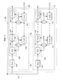
- FIG. 2 is a block diagram of an example configuration implementing an ANC system.
- FIG. 3 is a block diagram of an example filter coefficient update system implemented by the ANC system of FIG. 2 .
- FIG. 4 is an example operational flow diagram of the ANC system of FIGS. 2 and 3 .
- FIG. 5 is a system diagram of example computer that includes an ANC system.
- FIG. 6 is a block diagram of a multi-channel ANC system.
- FIG. 7 is a block diagram of a coefficient update system implemented within the multi-channel ANC system of FIG. 6 .
- FIG. 8 is a block diagram of the coefficient update system of FIG. 7 .
- An active noise control system may be configured to generate destructively interfering sound waves. This is accomplished generally by first determining presence of an undesired sound and then generating the destructively interfering sound waves.
- the destructively interfering sounds wave may be transmitted as a speaker output.
- a microphone may receive sound waves from the speaker output and the undesired sound. The microphone may generate an error signal based on the sound waves.
- the active noise control system may include at least one adaptive infinite impulse response (IIR) filter.
- the output signal of the adaptive IIR filter may be used to generate a signal to drive the speaker to produce the destructively interfering sound waves.
- An update system may determine update coefficients for the IIR filter. Determination of the update coefficients may be based on the output signal of the IIR filter.
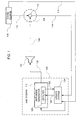
- an example active noise control (ANC) system 100 is diagrammatically shown.
- the ANC system 100 may be used to generate an anti-noise signal 102, which may be provided to drive a speaker 104 to produce sound waves as speaker output 106.
- the speaker output 106 may be transmitted to a target space 108 to destructively interfere with an undesired sound 110 present in a target space 108.
- anti-noise may be defined by sound waves of approximately equal amplitude and frequency and approximately 180 degrees out of phase with the undesired sound 110.
- the 180 degree shift of the anti-noise signal will cause destructive interference with the undesired sound in an area in which the anti-noise sound waves and the undesired sound 110 sound waves combine such as the target space 108.
- the ANC system 100 may be configured to generate anti-noise associated with various environments. For example, the ANC system 100 may be used to reduce or eliminate particular sounds present in a vehicle as perceived by a listener. In one example, the target space 108 may be selected in which to reduce or eliminate sounds related to vehicle operation such as engine noise or road noise. In one example, the ANC system 100 may be configured to eliminate an undesired sound with a frequency range of approximately 20-500 Hz.
- a microphone 112 may be positioned within or proximate to the target space 108 to detect sound waves present in the target space 108.
- the target space 108 may detect sound waves generated from the combination of the speaker output 106 and the undesired sound 110.
- the detection of the sound waves by the microphone 112 may cause an output signal to be generated by the microphone 112.
- the output signal may be used as an error signal 114.
- An input signal 116 may also be provided to the ANC system 100.
- the input signal 116 may be representative of the undesired sound 110 emanating from a sound source 118.
- the ANC system 100 may generate the anti-noise signal 102 based on the input signal 116.
- the ANC system 100 may use the error signal 114 to adjust the anti-noise signal 102 to more accurately cause destructive interference with the undesired sound 110 in the target space 108.
- the ANC system 100 may include an anti-noise generator 119.
- the ANC system 100 may be configured to include any number of anti-noise generators 119.
- the anti-noise generator 119 may be configured to generate the anti-noise signal 102 using at least one adaptive infinite impulse response (IIR) filter 120.
- IIR adaptive infinite impulse response
- the IIR filter 120 may converge faster than a finite impulse response (FIR) filter may converge when configured for use in the ANC system 100. Convergence speed may contribute to how quickly the anti-noise signal 102 is adapted to accurately cancel the undesired sound 110 in the target space 110.
- the ANC system 100 may include additional IIR filters.
- the adaptive IIR filter 120 may produce an IIR filter output signal 122 used to generate the anti-noise signal 102.
- the IIR filter 120 may include a plurality of filter coefficients that may be adapted based on the error signal 114 and the input signal 116.
- the coefficients of the IIR filter 120 may be updated using an update system 124.
- the update system 124 may be configured to provide update coefficients 126 to the IIR filter 120.
- the update system 124 may determine update coefficients 126 based on the error signal 114, the input signal 116, and the IIR filter output signal 122. In one example, update coefficients 126 may be determined for the IIR filter 120 between processing of samples of the input signal 116. Between each sample, the update system 124 may determine the update coefficients 126 and determine the stability of the updated coefficients 126. If the update coefficients 126 are stable, the update coefficients 126 may replace the current coefficients in the IIR filter 120 for subsequent samples of the input signal 116. If the update coefficients 126 are determined to be unstable, the IIR filter 120 may use the current coefficients for the subsequent samples of the input signal 116.
- the update system 124 may determine update coefficients between each sample of the input signal 116 provided to the anti-noise generator 119. Alternatively, the update system 124 may be configured to operate in parallel with the anti-noise generator 119.
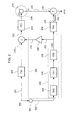
- an example ANC system 200 is shown in a Z-domain block diagram format.
- the ANC system 200 may include an IIR filter 202.
- the ANC system 200 may be configured to receive an input signal 204 representative of an undesired sound 207.
- "x(n)" may represent the state of the undesired sound 207 at a point of origin, detection, or both .
- the input signal 204 may be generated by a sensor 206, which may generate the input signal 204 based on receipt of the undesired sound (x(n)) 207.
- the sensor 206 may be a microphone configured to detect an undesired sound (x(n)) 207 and generate a representative signal in response to the detection.
- the input signal 204 may be based on a simulation of the undesired sound (x(n)) 207.
- the undesired sound 207 may propagate through a physical path that includes a first path 208 and second path 210 to reach a microphone 212 disposed within a target space 214.
- the first path 208 is represented by Z-domain transfer function F(z) and the second path 210 is represented as Z-domain transfer function S(z).
- the target space 214 may be a three-dimensional space targeted for cancellation the undesired sound 207 through generation of anti-noise.
- the first path 208 may represent the physical path traversed by the undesired sound 207 from an undesired sound source to a speaker 216 represented as a summation operation.
- An anti-noise signal 218 generated by the ANC system 200 may drive the speaker 216 to produce anti-noise that is combined with the undesired sound 207 at or proximate to the speaker 216.
- Sound waves 220 may include the combination of the undesired sound 207 and anti-noise based on the anti-noise signal 218.
- the anti-noise may traverse the second path 210 to the microphone 212. As the undesired sound 207 traverses the first path 208 and the second path 210, the state of the undesired sound 207 may change as perceived by a listener.
- the state of the undesired sound 207 as it combines with anti-noise at or proximate to the speaker 216 may be different than the state of the undesired sound 207 at its point of origin.
- the undesired sound 207 may sound differently to a listener in the target space 214 than the undesired sound 207 would sound to a listener at the source of the undesired sound 207.
- the state of the undesired sound 207 at or proximate to the microphone 212 may be represented as "d(n)".
- the undesired sound (d(n)) 207 may be perceived sound different to a listener than the undesired sound (x(n)) 207 at the source of the undesired sound.
- the undesired sound (d(n)) 207 at the microphone 212 may be the sound targeted to be reduced or eliminated because d(n) may be the state of the undesired sound 207 at the microphone perceived by a listener in the target space 214.
- the anti-noise signal 218 may be generated based on an output signal 222 of the IIR filter 202.
- the IIR filter 202 may include a plurality of filters cascaded in series. Each filter may include a respective transfer function.
- the IIR filter 202 may include a first filter 224, a second filter 226, and a second filter 228.
- B(z) may be a function of the -q th order and b q may represent each coefficient corresponding to an associated term in B(z).
- A(z) may be a function of the -p th order and a p represents each coefficient corresponding to an associated term in A(z).
- A(z) may be a non-zero function, which may create the possibility of instability in an IIR filter using a non-zero A(z) function.
- A(z) may be selected such that the denominator of H(z) may be factored into one or more biquadratic equation ("biquad") sections. Each biquad may be a second-order equation allowing the roots of each second-order equation to be determined.
- A(z) as one or more biquad sections allows an IIR filter to be represented by a plurality of second-order, cascaded filters, such as the second filter 226 and the third filter 228.
- A(z) may be selected allowing factorization into one or more biquad sections and a first order equation.
- the first filter 224 or "transversal" filter may be represented by B(z).
- the number and value of coefficients included in B(z) may be predetermined and adapted during operation of the ANC system 200.
- the second filter 226 and the third filter 228 of the IIR filter 202 may each be represented by biquad section filters in accordance with Eqn.
- the value of the coefficients of A 1 (z), a 11 and a 12 , and the coefficients of A 2 (z), a 21 and a 22 may be predetermined prior to initial operation of the ANC system 200 and adapted during operation.
- the output signal 222 represents the IIR filter 202 attempting to create a signal representative of the undesired sound 207 at the microphone 212, and thus the IIR filter 202 may represent an estimation of F(z).
- An inverter 230 may receive the output signal 222.
- the inverter 230 may invert the output signal 222 to produce the anti-noise signal 218.
- the inversion of the output signal 222 shifts the phase of the output signal 222 by approximately 180 degrees allowing anti-noise to be produced by the speaker 216.
- the microphone 212 may detect sound waves resulting from the combination of the anti-noise and the undesired sound (d(n)) 207.
- the microphone 212 may generate an output signal representative of a portion of the undesired sound (d(n)) 207 not canceled by the anti-noise.
- the output signal generated by the microphone 212 may be used as an error signal (e 1 ) 232 used by the IIR filter 202 to adjust the accuracy of the anti-noise.
- the error signal 232 may be provided to a summation operation 234 in which the error signal 232 is added to a filtered output signal 236.
- the filtered output signal 236 may be the output signal 222 of the IIR filter 202 filtered by an estimated path filter 238.
- the estimated path filter 238 represents an estimation of the second path 210.
- the estimated path filter 238 is represented by Z-domain transfer function ⁇ (z).
- the sum of the filtered output signal ( ⁇ (z)y(n)) 236 and the error signal (e 1 ) 232 may produce an update signal (d * (n)) 240 approximating the undesired sound x(n) at the microphone 212.
- the update signal 240 may be the actual targeted sound for cancellation since this is the state of the undesired sound x(n) in the target space 214.
- the update signal (d * (z)) 240 may represent the approximated state of the undesired sound (d(n)) 207 at the microphone 212.
- the state of the undesired sound 207 may change as it propagates through one or more mediums.
- the undesired sound (d(n)) 207 at the microphone 212 may be different than that represented by the input signal 204, representing x(n), input into the IIR filter 202.
- Generating anti-noise to approximate d(n) may allow the ANC system 200 to more accurately generate anti-noise.
- Coefficients of the adaptive IIR filter 202 may be updated in order to adjust the output signal 222 in order to adjust the accuracy of generated anti-noise.
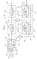
- a filter update system 300 implementing a backpropagation update configuration for the adaptive IIR filter 202 is shown.
- the undesired sound input signal 204 may include a plurality of samples. Each sample processed by the adaptive IIR filter 202 may ultimately generate a corresponding sample of the output signal 218.
- the update configuration of FIG. 3 may attempt to update the coefficients associated with the adaptive IIR filter 202 on a sample-by-sample basis. For example, in FIG.
- an input signal sample 301 of the input signal 204 may be designated as x(k), with k being a sample index.
- the sample x(k) may have propagated through the ANC system 200 to contribute to anti-noise generation.
- x(k+1) is received by the ANC system 200 and propagated through to contribute to anti-noise generation, the coefficients of the adaptive IIR filter 202 may be updated.
- the adaptive IIR filter 202 may be updated "offline," in other words, updated between the input samples being used to generate anti-noise.
- An update routine implementing backpropagation may be performed using an update system 300 shown in FIG. 3 .
- the last input signal sample (x(k)) 301 having propagated through the ANC system 200 may be stored for updating the adaptive IIR filter 202.
- history buffers for the ANC system 200 and the update system 300 may be different from one another.
- the first filter 224, second filter 226, and third filter 228 each include a first adaptive filter portion 302, second adaptive filter portion 304, and third adaptive filter portion 306, respectively.
- the first filter 224 may referred to as a transversal filter and include a learning algorithm unit (LAU) 308.
- the LAU 308 may implement a least mean squares (LMS) routine.
- LMS least mean squares
- other learning algorithms may be used, such as recursive least mean squares (RLMS), normalized least mean squares (NLMS), or any other suitable learning algorithm.
- the first filter 224 includes a predetermined number of coefficients.
- the coefficients of the first filter 224 may be implemented in the adaptive filter portion 302 representing the transfer function of the first filter 224.
- the second adaptive filter portion 304 and the third adaptive filter portion 306 may each include a transfer function represented as a biquad section resulting in two coefficients for the second adaptive filter portion 304 and the third adaptive filter portion 306.
- an estimated undesired sound sample (d * (k)) represents: e 1 (k)+ (y(k)) ⁇ (z), where y(k) is the output signal 222 ( FIG. 2 ) at sample index k, e 1 (k) is the error signal 232 ( FIG. 2 ) at sample index k, and ⁇ (z) is the transfer function of the estimated path filter 238 ( FIG. 2 ).
- the estimated undesired sound sample (d * (k)) may represent an update signal sample 307 of the update signal 240.
- the update system 300 may include a number of update filters 310.
- the update filters 310 may be serially cascaded as shown in FIG. 3 .
- the update signal sample (d * (k)) 307 may be input into a first update filter 314 having an first adaptive update filter portion 316 with a transfer function that is the reciprocal transfer function of the third adaptive filter portion 306, such that the first update filter 314 is functionally an FIR filter.
- the first update filter 314 may also include an LAU 318 configured to provide a first filter update signal 319 to the filter portion 316.
- the LAU 318 may implement a LMS routine, recursive least mean squares (RLMS), normalized least mean squares (NLMS), or any other suitable learning algorithm.
- the first update filter 314 generates a first update filter output signal 320 that may be provided to a second update filter 322, as well as a first operator 324.
- the second update filter 322 may include a second adaptive update filter portion 326 having a transfer function that is the reciprocal transfer function of the second adaptive filter portion 304.
- the second update filter 322 may also include an LAU 328 configured provide a first coefficient update signal 329 to the second adaptive update filter portion 326 to update the respective coefficients.
- the second update filter 322 may generate a second update filter output signal 330.
- the second update filter output signal 330 may be provided to a second operator 332.
- the associated input signal sample x(k) 301 may be input into the update system 300.
- the input signal sample (x(k)) 301 may be provided to the estimated path filter 238.
- the filtered input signal sample 334 is provided to the first filter 224 including the first adaptive filter portion 302 and the LAU 308.
- the first filter 224 may generate a first intermediate output signal 336 based on the filtered input sample 334.
- the first intermediate output signal 336 may be provided to the second filter 226 and to the second operator 332.
- the second filter 226 may generate a second intermediate output signal 338 based on the first intermediate output signal 336.
- the second intermediate output signal 338 may be provided to the third filter 228 and the first operator 324.
- the third filter 228 may generate a filter output signal 340.
- the filter output signal 340 may be disregarded in the update system 300.
- Processing of the signal samples 301 and 307 and the intermediate output signals 320, 330, 336, and 338 by the respective filters may allow intermediate error signals to be generated.
- a first intermediate error signal 342 may be generated at the second operator 332 by subtracting the first intermediate output signal 336 from the second update filter output signal 330.
- the first intermediate error signal 342 may be provided to the first filters 224 and the second update filter 322.
- the first filter 224 and the second update filter 332 may use the first intermediate error signal 342 to update the respective coefficients through the LAUs 308 and 328, respectively.
- a second intermediate error signal 344 may be generated at the first operator 324 by subtracting the second intermediate output signal 338 from the first update filter output signal 320.
- the second intermediate error signal 344 may be provided to the LAU 318 of the first update filter 314 to update the coefficients of the first adaptive update filter portion 316.
- the LAU 308 may use the intermediate error signals 342, as well as the filtered input signal 334 to generate an update signal 309.
- the LAUs 318 and 328 may use the intermediate error signals 344 and 342, respectively, and the intermediate output signals 320 and 330, respectively, to generate an update signal 319 and 329, respectively, which is provided to the respective filter portions 316 and 326.
- stability determinations may be made for the coefficients.
- the coefficients for the adaptive update filter portions 316 and 326 may be checked for stability by determining a region of stability for each set of coefficients for the corresponding update filter 316 and 326.
- the stability may be determined through the following equations: 1 + a i ⁇ 1 - a i ⁇ 2 > 0 1 + a i ⁇ 1 + a i ⁇ 2 > 0 1 + a i ⁇ 2 > 0 where a i1 and a i2 are the set of coefficients for each biquad. If Eqns. 9-11 are true for a set of biquad coefficients, then the coefficients are stable. If any one of the Eqns. 9-11 is false, the coefficients are unstable.
- the corresponding adaptive filter portions 306 and 304 may each have the coefficients updated to include the update coefficients. For example, if the update coefficients of the adaptive update filter portions 316 and 326 are determined to be stable, the third adaptive filter portion 306 may be updated with the update coefficients of the first adaptive update filter portion 316 and the coefficients of the second adaptive filter portion 304 may be updated with the coefficients of the second adaptive update filter portion 326.
- any of the update coefficients of the update filters 314 and 322 are determined to be unstable, none of the coefficients may be used to update a corresponding filter.
- the filter 224 also may not use coefficients based on the signal sample 301. If the coefficients are not used to update the filters 224, 226, and 228, the filters 224, 226, and 228 may continue to use the current coefficients for the next input signal sample x(k+1). The decision to update or not update a particular filter may be performed on a sample-by-sample basis. Once updating decisions and associated updates occur, the filters 224, 226, and 228 may be in condition to receive the next input sample x(k+1).
- FIG. 4 is a flow diagram of an example operation of an ANC system configured to generate anti-noise using adaptive IIR filters, such as the ANC system 200.
- the operation may include a step 400 of generating an output signal sample based on an input signal sample.
- the step 400 may be performed by providing an input signal sample (x(k)) 301 to the IIR filter 202.
- the IIR filter 202 may include the cascaded filters 224, 226, and 228.
- Each sample of the input signal 204 may generate an associated sample of the output signal 222.
- the output signal 222 may be inverted to generate the anti-noise signal 218.
- the operation may include a step 402 of generating an error signal sample based on the output signal sample.
- the error signal 232 may be an output signal generated by the microphone 212.
- the error signal 232 may be received by the ANC system 200.
- the error signal 232 may represent sound waves detected by the microphone 212 resulting from the combination at the microphone 212 of speaker output representing anti-noise and the undesired sound (d(n)) 207 proximate to the microphone 212.
- a sample of the error signal 232 may be corresponding to a sample of the output signal 222.
- the operation may include a step 404 of generating an update signal sample d * (k) based on the error signal sample 232 and a filtered output signal sample 236.
- the update signal sample d * (k) may be generated by summing an error signal sample and an output signal sample of the IIR filter 202 filtered by the estimated path filter 238, as shown in the ANC system 200.
- a sample y(k) of the output signal 222 of the anti-noise generator filter 202 is filtered by the estimated path filter 238 and summed with a corresponding sample e 1 (k) of the error signal 232 at the summation operator 234.
- the resulting signal is the update signal 240 representing the estimated undesired sound d * (n) at the corresponding sample index k.
- the estimated undesired sound signal (d * (n)) 240 at a sample index k is represented by the update signal sample (d * (k)) 307.
- the operation may include a step 406 of determining updated filter coefficients based on the update signal sample d * (k) and a filtered input signal sample.
- Step 406 may be performed in the ANC system 200 using the update system 300 in FIG. 3 .
- Each sample of the input signal 204 may be processed by the ANC system 200 to generate a corresponding sample of the anti-noise signal 218 used to drive the speaker 216 to produce anti-noise.
- the update system 300 may use the IIR filter 202 to update the coefficients of the first filter 224, second filter 226, and third filter 228.
- the current input signal sample, x(k) may be filtered by the estimated path filter 238.
- the filtered signal 334 may be provided to the IIR filter 202.
- the update signal sample (d * (k)) 307 may be provided to the first update filter 314.
- a backpropagation configuration may be implemented to update the coefficients of the filters 224, 226, and 228.
- the transfer function of the second filter 226 and third filter 228 may each represent a biquad section of the IIR filter 202. The form of the transfer function allows the possibility of system instabilility to occur based on the selected coefficients.
- Each update filter 314 and 322 may have the update coefficients of the adaptive update filter portions 316 and 326, respectively, determined based using the update system 300.
- the update coefficients determined for the update filters 314 and 322 may be checked for stability. In one example, this may be performed using Eqn. 9-11.
- the operation of FIG. 4 may be performed for each update filter 314 and 322.
- the operation may include a step 410 of determining if each determined coefficient of an update filter is stable. If the coefficients are all stable, a step 412 may be performed of updating the IIR filter 202 with the update coefficients. If the update coefficients are unstable, a step 414 may be performed of maintaining the current coefficients of the IIR filter 202.
- the steps 410 through 414 may be performed for each IIR filter in the ANC system.
- a step 416 of receiving a next input signal sample may be performed. Upon performance of step 416, the operation may perform step 400 using the next input signal sample.
- FIG. 5 shows of an example ANC system 500 that may be implemented on a computer device 502.
- the computer device 502 may be an audio/video system, such as that used in vehicles or other suitable environment.
- the computer device 502 may include a processor 504 and a memory 506, which may be implemented to generate a software-based ANC system, such as the ANC system 500.
- the ANC system 500 may be implemented as instructions stored on the memory 506 executable by the processor 504.
- the memory 506 may be computer-readable storage media or memories, such as a cache, buffer, RAM, ROM, removable media, hard drive or other computer-readable storage media.
- Computer-readable storage media include various types of volatile and nonvolatile storage media.
- Various processing techniques may be implemented by the processor 504 such as multiprocessing, multitasking, parallel processing and the like, for example.
- the ANC system 500 may be implemented to generate anti-noise to destructively interfere with an undesired sound 508 in a target space 510.
- the undesired sound 508 may emanate from a sound source 512.
- At least one sensor 514 may detect the undesired sound 508.
- the sensor 514 may be various forms of detection devices depending on a particular ANC implementation.
- the ANC system 500 may be configured to generate anti-noise in a vehicle to destructively interfere with engine noise.
- the sensor 514 may be an accelerometer or vibration monitor configured to generate a signal based on the engine noise.
- the sensor 514 may also be a microphone configured to receive the engine noise as a sound wave in order to generate a representative signal for use by the ANC system 500.
- any other undesirable sound may be detected within a vehicle, such as fan or road noise.
- the sensor 514 may generate an analog-based signal 516 representative of the undesired sound that may be transmitted through an electrical connection 518 to an analog-to-digital (A/D) converter 520.
- the A/D converter 520 may digitize the signal 516 and transmit the digitized signal 522 to the computer device 502 through a connection 523.
- the A/D converter 520 may be instructions stored on the memory 506 that are executable by the processor 504.
- the ANC system 500 may generate an anti-noise signal 524 that may be transmitted through a connection 525 to a digital-to-analog (D/A) converter 526.
- the D/A converter 526 may generate an analog-based anti-noise signal 528 that may be transmitted through an electrical connection 530 to a speaker 532 to drive the speaker to produce anti-noise sound waves as speaker output 534.
- the speaker output 534 may be transmitted to the target space 510 to destructively interfere with the undesired sound 508.
- the D/A converter 526 may be instructions stored on the memory 506 and executed by the processor 504.
- a microphone 536 or other sensing device may be positioned within the target space 510 to detect sound waves present within or proximate to the target space 510.
- the microphone 536 may detect sound waves remaining after occurrence of destructive interference between the speaker output 534 of anti-noise and the undesired sound 508.
- the microphone 536 may generate a signal 538 representative of the detected sound waves.
- the signal 538 may be transmitted through a connection 540 to an A/D converter 542 where the signal may be digitized as signal 544 and transmitted through a connection 546 to the computer 502.
- the signal 544 may represent an error signal similar to that discussed in regard to FIGS. 1 and 2 .
- the A/D converter 542 may be instructions stored on the memory 506 and executed by the processor 504,
- the ANC system 500 may operate in a manner similar to that described in regard to FIGS. 2 .
- the ANC system 500 may include an anti-noise generator 548 configured with an IIR filter 550.
- the IIR filter 550 may include a plurality of cascaded filters.
- an IIR filter may include a transversal filter and a number of biquad filters.
- the number of coefficients may be chosen for the denominator portion of Eqn. 2, A(z), to produce N different biquads.
- the number N may vary per ANC system configuration. In one example N may be 10 biquads, but may be increased or decreased in number.
- the IIR filter 550 may receive the input signal 522 indicative of the undesired sound 508 and generate an output signal 552.
- the output signal 552 may be provided to an inverter 554 to generate the anti-noise signal 524.
- coefficients of an IIR filter in an ANC system may be updated between generating an output signal sample based on an input signal sample.
- the IIR filter 550 includes a transversal filter 556 and N biquad section filters 558 designated as "1/A(z) 1 " through "1/A(z) N ".
- the system of FIG. 5 may implement an update system 501 to update the coefficients in the filters 556 and 558 of the IIR filter 550.
- the filters 556 and 558 of the IIR filter 550 may be updated when the ANC system is offline, as indicated by the arrow 560.
- the term "offline" may refer to the time between samples of the input signal 522 provided to the IIR filter 550.
- the processor 304 and memory 306 may be configured to execute the update system 501 of the ANC system 500 between samples being provided to the IIR filter 550.
- the update system 501 may be configured to receive each sample of the input signal 522 received by the IIR filter 550.
- the input signal sample may be provided to an estimated path filter 562 represented in FIG. 5 as Z-domain transfer function ⁇ (z).
- the estimated path filter 562 may represent an estimation of the effect on sound waves propagating along a path from the speaker 532 to the microphone 536, as well as components used to generate the anti-noise signal 524.
- the update system 501 is shown as part of the ANC system 500. In alternative examples, the coefficient update system 501 may be executed independently from the ANC system 500 by the computer device 502 or another computer device.
- the update system 501 may include the filters present in the IIR filter 550.
- a filtered input signal 564 of the estimated path filter 562 may be provided to the IIR filter 550 in the update system 501.
- the output signal 552 of the IIR filter 550 may be implemented by the update system 501.
- the IIR filter output signal 552 may be provide to the estimated path filter 562.
- the filtered output signal 568 of the estimated path filter 562 may be provided to a summation operator 566.
- the filtered output signal 568 may be summed with the error signal 544 at the summation operator 566 to produce an update signal 569.
- the coefficient update system 501 may include a plurality of update filters 570, designated individually as “A(z) 1 " through “A(z) N ", with each one corresponding to one of the filters 558 and being configured to include the reciprocal of the transfer function of a corresponding filter 558. Similar to the update system 300 of FIG. 3 , in the update system 501, a sample of the filtered input signal 564 may be provided to the transversal filter 556 of the update system 501 allowing the sample to be processed by the IIR filter 550. The update signal 569 may be provided as an input to the update filters 570.
- intermediate output signals may be generated by the filters 556, 558, and 570 and provided to operators in an arrangement according to that shown in FIG. 5 and similar to that described in with regard to the update system 300.
- the update coefficients of the filters 570 may be checked for stability using Eqns. 9-11. If all update coefficients of the filters 570 are determined to be stable, each filter 558 may be updated with the update coefficients of a corresponding filter 570. If any one of the update coefficients is determined to be unstable, none of the filters 556 and 558 may be updated and the filters 556 and 558 may use the current coefficients for the next input signal sample.
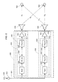
- FIG. 6 shows a block diagram of an example multi-channel ANC system 600.
- the multi-channel ANC system 600 includes two channels, however, more channels may be implemented.
- the ANC system 600 includes a first anti-noise generator 602 and a second anti-noise generator 604.
- the first and second anti-noise generators 602 and 604 may each include at least one adaptive IIR filter.
- the first anti-noise generator 602 includes a first IIR filter 606 and the second anti-noise generator includes a second IIR filter 608.
- Each anti-noise generator 602 and 604 may include a first and second inverter 610 and 612, respectively, to invert a first filter output signal 611 and a second output filter signal 613, respectively, produced by the respective first IIR filter 606 and second IIR filter 608.
- a first anti-noise signal 614 and a second anti-noise signal 616 generated by the first anti-noise generator 602 and the second anti-noise generator 604, respectively, may drive a respective speaker 618 and 620 to produce anti-noise.
- the ANC system 600 may include a first and second error microphone 622 and 624. Each error microphone 622 and 624 may be disposed in a space targeted to reduce or eliminate an undesired sound. Each error microphone 622 and 624 may receive anti-noise from both speakers 618 and 620. Secondary path S 11 may represent a path traversed by sound waves produced by the first speaker 618 to the first error microphone 622. Secondary path S 21 may represent a path traversed by sound waves produced by the first speaker 618 to the second error microphone 624. Secondary path S 22 may represent a path traversed by sound waves produced by the second speaker 620 to the second error microphone 624. Secondary path S 12 may represent a path traversed by sound waves produced by the second speaker 620 to the first error microphone 622.
- a reference signal 601 representative of an undesired sound (x(n)) 605 generated by a sensor 603 may be provided to the first anti-noise generator 602 and the second anti-noise generator 604.
- the undesired sound 605 may be simulated allowing the simulated sound to be provided as an input signal to each anti-noise generator 602 and 604.
- the first IIR filter 606 may include a plurality of filters.
- the first IIR filter 606 may include a first filter 626 represented in FIG. 6 as B 1 (z).
- the first IIR filter 606 may also include a number of filters 628 each representing a biquad section filter of the IIR filter 606.
- the IIR filter 606 may include N biquad section filters 528 individually designated as “1/A 11 (z)" through “1/A 1N (z)".
- the second IIR filter 608 may include a first filter 630 represented as “B 2 (z)” and a number of filters 632 each representing a biquad section.
- the IIR filter 608 may include P biquad section filters 632 individually designated as "1/A 21 (z)” through “1/A 2P (z)".
- the first IIR filter 606 and the second IIR filter 608 may or may not include the same number of biquad sections N and P, respectively.
- FIGS. 7 and 8 shows a block diagram of a filter update system 700 that may be used with the multi-channel ANC system 600.
- the update system 700 may operate independently from the ANC system 600 or as a part of the ANC system 600.
- the filter update system 700 may be configured to update the filter coefficients associated with the first and second IIR filters 606 and 608.
- the update system 700 may include a first filter update sub-system 702 and a second filter update sub-system 704.
- the first and second filter update sub-systems 702 and 704 may each be configured to update one of the first and second IIR filters 606 and 608, respectively.
- the first and second filter update sub-systems 702 and 704 may operate in a manner similar to that described with regard to the filter update system 300, however, the sub-systems 702 and 704 may include multi-stage updating to account for the multi-channel configuration of the ANC system 600.
- FIG. 7 shows a first stage of updating coefficients of the first and second IIR filters 606 and 608.
- the first stage of the filter update sub-system 702 may be configured to include the first IIR filter 606 and a first estimated path filter 706.
- the first estimated path filter 706 may represent a transfer function estimate of the physical path from the first speaker 618 to the first error microphone 622 and the path traversed by a signal through components associated with the first speaker 618 and the first error microphone 622.
- the first estimated path filter 706 is represented as Z-transform transfer function ⁇ 11 (z) in FIG. 7 .
- the first filter update sub-system 702 may also include a number of first stage update filters 708,
- an input signal sample (x(k)) 701 of the reference signal 601 representative of the undesired sound (x(n)) 605 is provided to the update sub-system 702.
- a first estimated undesired sound signal sample (d * 1 (k)) 703 may be provided to the first stage update filters 708.
- the first estimated undesired sound signal sample (d * 1 (k)) 703 may be representative of the estimated state of the undesired sound 605 at the error microphone 622.
- the first stage of the update sub-system 702 may operate in a similar manner as the update system 300 in updating coefficients in the IIR filter 606.
- Each first stage update filter 708 is configured to include the reciprocal transfer function of a corresponding biquad section filter of the IIR filter 606.
- one biquad section filter 628 of the first IIR filter 606 may be include a transfer function of 1/A 11 (z), with A 11 (z) having a form similar to Eqn. 6.
- One of the first stage update filters 708 may include a corresponding filter having a transfer function of A 11 (z) in the same form as Eqn. 6.
- the coefficients associated with each update filter 708 may be used to update a corresponding biquad section filter 628.
- the updated coefficients may be determined through an arrangement involving intermediate output signals and intermediate error signals as shown in FIG. 6 , similar to that described with regard to FIG. 3 . If any one of the updated coefficients of the first stage update filters 708 is determined to be unstable, none of the filters 626 and 628 are updated and the current coefficients will be maintained.
- the second update sub-system 704 may operate in substantially the same manner as the first update sub-system 702.
- the second update sub-system 704 may receive the undesired sound sample (x(k)) 701 and filter the sample x(k) with a second estimated path filter 710, represented by Z-domain transfer function ⁇ 22 (z).
- the second estimated path filter 710 may represent a transfer function estimate of the physical path between second speaker 620 and the second error microphone 624, as well as components associated with the second speaker 620 and the second error microphone 624.
- the second update sub-system 704 may include a number of first stage update filters 712.
- the first stage update filters 712 may be configured in manner similar to the first stage update filters 708.
- the end update filter 712 may receive a second estimated undesired sound signal (d 2 * (k)) 713.
- the second estimated undesired sound signal d 2 * (k) may represent the state of the undesired sound sample x(k) at the error microphone 624.
- the biquad section filters 632 may be updated in a manner similar to that described with regard to the first update sub-system 702. If any updated coefficient of first stage update filters 712 are determined to be unstable, none of the filters 630 and 632 are updated and the current coefficients may be maintained.
- the filters 626 and 630 and each of the first update filters 708 and 712 may include a filter portion and an LAU, similar to the update system 300 as similarly shown in FIG. 3 .
- a second update stage may be implemented to account for the multi-channel arrangement.
- the IIR filters 606 and 608 may be updated to account for the S 21 and S 12 secondary paths, respectively, after the update shown in FIG. 7 .
- the update sub-system 702 may include second stage update filters 802.
- the input signal sample (x(k)) 701 of the input signal x(n) representative of the undesired sound may be provided to a third estimated path filter 800 of the update sub-system 702.
- the second estimated undesired sound signal sample (d * 2 (k)) 713 may be provided to the second stage update filters 802.
- the third estimated path filter 800 may represent a transfer function estimate of the physical path from the first speaker 618 to the second error microphone 624 and the path traversed by a signal through components associated with the first speaker 618 and the second error microphone 624.
- the estimated path filter 800 is represented as Z-transform transfer function ⁇ 21 (z) in FIG. 8 .
- the second stage of the update sub-system 702 may also operate in a similar manner as the update system 300 in updating coefficients in the IIR filter 606.
- the transfer function of each filter 628 is designated as "1/A * 11 (z) through 1/A * 1N (Z), where the "*" indicates that the filters 628 have been through the first update stage.
- the coefficients for the filters 628 in the second stage may be updated from those determined at the first stage or may be the coefficients prior to the first stage operation depending on the stability of the coefficients determined in the first stage.
- Each second stage update filter 802 is configured to include the reciprocal transfer function of a corresponding biquad section filter 628 of the IIR filter 606.
- the coefficients associated with each second stage update filter 802 may be used to update a corresponding biquad section filter 628.
- the updated coefficients for the second stage may be determined through an arrangement involving intermediate output signals and intermediate error signals as shown in FIG. 6 , similar to that described with regard to FIG. 3 . If any updated coefficient of second stage update filters 802 are determined to be unstable, none of the filters 626 and 628 are updated and the current coefficients will be used for the next input signal sample x(k+1).
- the second stage of the second update sub-system 704 may operate in substantially the same manner as the second stage of the first update sub-system 702.
- the second update sub-system 704 may receive the undesired sound sample 701 (x(k)) and filter the sample x(k) with a fourth estimated path filter 804, represented by Z-domain transfer function ⁇ 12 (z).
- the fourth estimated path filter 804 may represent a transfer function estimate of the physical path between second speaker 620 and the first error microphone 622, as well as components associated with the second speaker 620 and the first error microphone 622.
- each filter 632 is designated as "1/A * 21 (z) through 1/A * 2P (Z), where the "*" indicates that the filters 632 have been through the first stage.
- the second update sub-system 704 may include a number of second stage update filters 806.
- the second stage update filters 806 may be configured in manner similar to the second stage update filters 802.
- the end update filter 806, represented as A * 2P (z) may receive the first estimated undesired sound signal (d 1 * (k)) 703.
- the biquad section filters 632 may be updated in manner similar to that described with regard to the first update sub-system 702. If any updated coefficient of second stage update filters 806 are determined to be unstable, none of the filters 630 and 632 are updated and the current coefficients will be used for the next input signal sample x(k+1).
- the second stage update filters 802 and 806 may include a filter portion and an LAU, similar to the update system 300 shown in FIG. 3 .
Abstract
Description
- This invention relates to active noise control, and more specifically to active noise control using at least one infinite impulse response filter.
- Active noise control may be used to generate sound waves that destructively interfere with a targeted undesired sound. The destructively interfering sound waves may be produced through a loudspeaker to combine with the targeted undesired sound.
- An active noise control system generally includes at least one adaptive finite impulse response (FIR) filter. FIR filters are typically used due to low incidence of system instability. FIR filters generally display longer convergence times as compared to infinite impulse response (IIR) filters. While IIR filters may provide lower convergence times as compared to FIR filters, use of IIR filters may result in more instances of system instability. Therefore, a need exists to control IIR filter stability in active noise control systems.
- An active noise control (ANC) system may implement at least one adaptive infinite impulse response (IIR). The IIR filter may receive an input signal representative of an undesired sound. The IIR filter may generate an output signal based on the input signal. The ANC system may generate an anti-noise signal based on the output signal of IIR filter. The anti-noise signal may be used to drive a speaker to generate sound waves to destructively interfere with the undesired sound.
- The IIR filter may include a plurality of filter coefficients used to generate the output signal based on the input signal. The ANC system may include an update system to update the filter coefficients of the IIR filter. The update system may generate a plurality of update coefficients based on each sample of the input signal being received by the IIR filter. The update system may determine the stability of the update coefficients. The coefficients of the IIR filter may be replaced with the update coefficients when the update coefficients are determined to be stable.
- Other systems, methods, features and advantages of the invention will be, or will become, apparent to one with skill in the art upon examination of the following figures and detailed description. It is intended that all such additional systems, methods, features and advantages be included within this description, be within the scope of the invention, and be protected by the following claims.
- The system may be better understood with reference to the following drawings and description. The components in the figures are not necessarily to scale, emphasis instead being placed upon illustrating the principles of the invention. Moreover, in the figures, like referenced numerals designate corresponding parts throughout the different views.
-
FIG. 1 is a diagrammatic view of an example active noise control (ANC) system. -
FIG. 2 is a block diagram of an example configuration implementing an ANC system. -
FIG. 3 is a block diagram of an example filter coefficient update system implemented by the ANC system ofFIG. 2 . -
FIG. 4 is an example operational flow diagram of the ANC system ofFIGS. 2 and3 . -
FIG. 5 is a system diagram of example computer that includes an ANC system. -
FIG. 6 is a block diagram of a multi-channel ANC system. -
FIG. 7 is a block diagram of a coefficient update system implemented within the multi-channel ANC system ofFIG. 6 . -
FIG. 8 is a block diagram of the coefficient update system ofFIG. 7 . - An active noise control system may be configured to generate destructively interfering sound waves. This is accomplished generally by first determining presence of an undesired sound and then generating the destructively interfering sound waves. The destructively interfering sounds wave may be transmitted as a speaker output. A microphone may receive sound waves from the speaker output and the undesired sound. The microphone may generate an error signal based on the sound waves. The active noise control system may include at least one adaptive infinite impulse response (IIR) filter. The output signal of the adaptive IIR filter may be used to generate a signal to drive the speaker to produce the destructively interfering sound waves. An update system may determine update coefficients for the IIR filter. Determination of the update coefficients may be based on the output signal of the IIR filter.
- In
FIG. 1 , an example active noise control (ANC)system 100 is diagrammatically shown. The ANCsystem 100 may be used to generate ananti-noise signal 102, which may be provided to drive aspeaker 104 to produce sound waves asspeaker output 106. Thespeaker output 106 may be transmitted to atarget space 108 to destructively interfere with anundesired sound 110 present in atarget space 108. In one example, anti-noise may be defined by sound waves of approximately equal amplitude and frequency and approximately 180 degrees out of phase with theundesired sound 110. The 180 degree shift of the anti-noise signal will cause destructive interference with the undesired sound in an area in which the anti-noise sound waves and theundesired sound 110 sound waves combine such as thetarget space 108. The ANCsystem 100 may be configured to generate anti-noise associated with various environments. For example, the ANCsystem 100 may be used to reduce or eliminate particular sounds present in a vehicle as perceived by a listener. In one example, thetarget space 108 may be selected in which to reduce or eliminate sounds related to vehicle operation such as engine noise or road noise. In one example, the ANCsystem 100 may be configured to eliminate an undesired sound with a frequency range of approximately 20-500 Hz. - A
microphone 112 may be positioned within or proximate to thetarget space 108 to detect sound waves present in thetarget space 108. In one example, thetarget space 108 may detect sound waves generated from the combination of thespeaker output 106 and theundesired sound 110. The detection of the sound waves by themicrophone 112 may cause an output signal to be generated by themicrophone 112. The output signal may be used as anerror signal 114. Aninput signal 116 may also be provided to the ANCsystem 100. Theinput signal 116 may be representative of theundesired sound 110 emanating from asound source 118. The ANCsystem 100 may generate theanti-noise signal 102 based on theinput signal 116. The ANCsystem 100 may use theerror signal 114 to adjust theanti-noise signal 102 to more accurately cause destructive interference with theundesired sound 110 in thetarget space 108. - In one example, the ANC
system 100 may include ananti-noise generator 119. TheANC system 100 may be configured to include any number ofanti-noise generators 119. Theanti-noise generator 119 may be configured to generate theanti-noise signal 102 using at least one adaptive infinite impulse response (IIR)filter 120. In one example, theIIR filter 120 may converge faster than a finite impulse response (FIR) filter may converge when configured for use in theANC system 100. Convergence speed may contribute to how quickly theanti-noise signal 102 is adapted to accurately cancel theundesired sound 110 in thetarget space 110. In alternative examples, theANC system 100 may include additional IIR filters. Theadaptive IIR filter 120 may produce an IIRfilter output signal 122 used to generate theanti-noise signal 102. TheIIR filter 120 may include a plurality of filter coefficients that may be adapted based on theerror signal 114 and theinput signal 116. The coefficients of theIIR filter 120 may be updated using an update system 124. - The update system 124 may be configured to provide
update coefficients 126 to theIIR filter 120. The update system 124 may determineupdate coefficients 126 based on theerror signal 114, theinput signal 116, and the IIRfilter output signal 122. In one example, updatecoefficients 126 may be determined for theIIR filter 120 between processing of samples of theinput signal 116. Between each sample, the update system 124 may determine theupdate coefficients 126 and determine the stability of the updatedcoefficients 126. If theupdate coefficients 126 are stable, theupdate coefficients 126 may replace the current coefficients in theIIR filter 120 for subsequent samples of theinput signal 116. If theupdate coefficients 126 are determined to be unstable, theIIR filter 120 may use the current coefficients for the subsequent samples of theinput signal 116. The update system 124 may determine update coefficients between each sample of theinput signal 116 provided to theanti-noise generator 119. Alternatively, the update system 124 may be configured to operate in parallel with theanti-noise generator 119. - In
FIG. 2 , anexample ANC system 200 is shown in a Z-domain block diagram format. TheANC system 200 may include anIIR filter 202. TheANC system 200 may be configured to receive aninput signal 204 representative of anundesired sound 207. InFIG. 2 , "x(n)" may represent the state of theundesired sound 207 at a point of origin, detection, or both . Theinput signal 204 may be generated by asensor 206, which may generate theinput signal 204 based on receipt of the undesired sound (x(n)) 207. In one example, thesensor 206 may be a microphone configured to detect an undesired sound (x(n)) 207 and generate a representative signal in response to the detection. Alternatively, theinput signal 204 may be based on a simulation of the undesired sound (x(n)) 207. - The
undesired sound 207 may propagate through a physical path that includes afirst path 208 andsecond path 210 to reach amicrophone 212 disposed within atarget space 214. InFIG. 2 , thefirst path 208 is represented by Z-domain transfer function F(z) and thesecond path 210 is represented as Z-domain transfer function S(z). Thetarget space 214 may be a three-dimensional space targeted for cancellation theundesired sound 207 through generation of anti-noise. Thefirst path 208 may represent the physical path traversed by theundesired sound 207 from an undesired sound source to aspeaker 216 represented as a summation operation. Ananti-noise signal 218 generated by theANC system 200 may drive thespeaker 216 to produce anti-noise that is combined with theundesired sound 207 at or proximate to thespeaker 216.Sound waves 220 may include the combination of theundesired sound 207 and anti-noise based on theanti-noise signal 218. The anti-noise may traverse thesecond path 210 to themicrophone 212. As theundesired sound 207 traverses thefirst path 208 and thesecond path 210, the state of theundesired sound 207 may change as perceived by a listener. As a result, the state of theundesired sound 207 as it combines with anti-noise at or proximate to thespeaker 216 may be different than the state of theundesired sound 207 at its point of origin. Also, theundesired sound 207 may sound differently to a listener in thetarget space 214 than theundesired sound 207 would sound to a listener at the source of theundesired sound 207. - In
FIG. 2 , the state of theundesired sound 207 at or proximate to themicrophone 212 may be represented as "d(n)". As described, the undesired sound (d(n)) 207 may be perceived sound different to a listener than the undesired sound (x(n)) 207 at the source of the undesired sound. The undesired sound (d(n)) 207 at themicrophone 212 may be the sound targeted to be reduced or eliminated because d(n) may be the state of theundesired sound 207 at the microphone perceived by a listener in thetarget space 214. - The
anti-noise signal 218 may be generated based on anoutput signal 222 of theIIR filter 202. TheIIR filter 202 may include a plurality of filters cascaded in series. Each filter may include a respective transfer function. InFIG. 2 , theIIR filter 202 may include afirst filter 224, asecond filter 226, and asecond filter 228. Generally a digital filter, may be represented by the relationship of:


- In a finite impulse response (FIR) filter, A(z) is one (=1) resulting in H(z) being B(z) in Eqn. 2. In an IIR filter, A(z) may be a non-zero function, which may create the possibility of instability in an IIR filter using a non-zero A(z) function. In one example, A(z) may be selected such that the denominator of H(z) may be factored into one or more biquadratic equation ("biquad") sections. Each biquad may be a second-order equation allowing the roots of each second-order equation to be determined. Representing A(z) as one or more biquad sections allows an IIR filter to be represented by a plurality of second-order, cascaded filters, such as the
second filter 226 and thethird filter 228. Alternatively, A(z) may be selected allowing factorization into one or more biquad sections and a first order equation. - In accordance with Eqn. 3, one of the cascaded filters may include coefficients associated with B(z) such that:

FIG. 2 , thefirst filter 224 or "transversal" filter may be represented by B(z). The number and value of coefficients included in B(z) may be predetermined and adapted during operation of theANC system 200. In one example, thesecond filter 226 and thethird filter 228 of theIIR filter 202 may each be represented by biquad section filters in accordance with Eqn. 4 such as:
and
ANC system 200 and adapted during operation. - The
output signal 222 represents theIIR filter 202 attempting to create a signal representative of theundesired sound 207 at themicrophone 212, and thus theIIR filter 202 may represent an estimation of F(z). Aninverter 230 may receive theoutput signal 222. Theinverter 230 may invert theoutput signal 222 to produce theanti-noise signal 218. The inversion of theoutput signal 222 shifts the phase of theoutput signal 222 by approximately 180 degrees allowing anti-noise to be produced by thespeaker 216. - The
microphone 212 may detect sound waves resulting from the combination of the anti-noise and the undesired sound (d(n)) 207. Themicrophone 212 may generate an output signal representative of a portion of the undesired sound (d(n)) 207 not canceled by the anti-noise. The output signal generated by themicrophone 212 may be used as an error signal (e1) 232 used by theIIR filter 202 to adjust the accuracy of the anti-noise. - The
error signal 232 may be provided to asummation operation 234 in which theerror signal 232 is added to a filteredoutput signal 236. The filteredoutput signal 236 may be theoutput signal 222 of theIIR filter 202 filtered by an estimatedpath filter 238. The estimated path filter 238 represents an estimation of thesecond path 210. The estimated path filter 238 is represented by Z-domain transfer function Ŝ(z). The sum of the filtered output signal (Ŝ(z)y(n)) 236 and the error signal (e1) 232 may produce an update signal (d*(n)) 240 approximating the undesired sound x(n) at themicrophone 212. The update signal may be represented by:
update signal 240 may be the actual targeted sound for cancellation since this is the state of the undesired sound x(n) in thetarget space 214. - In
FIG. 2 , the update signal (d*(z)) 240 may represent the approximated state of the undesired sound (d(n)) 207 at themicrophone 212. The state of theundesired sound 207 may change as it propagates through one or more mediums. As a result, the undesired sound (d(n)) 207 at themicrophone 212 may be different than that represented by theinput signal 204, representing x(n), input into theIIR filter 202. Generating anti-noise to approximate d(n) may allow theANC system 200 to more accurately generate anti-noise. - Coefficients of the
adaptive IIR filter 202 may be updated in order to adjust theoutput signal 222 in order to adjust the accuracy of generated anti-noise. InFIG. 3 , afilter update system 300 implementing a backpropagation update configuration for theadaptive IIR filter 202 is shown. In one example, the undesiredsound input signal 204 may include a plurality of samples. Each sample processed by theadaptive IIR filter 202 may ultimately generate a corresponding sample of theoutput signal 218. The update configuration ofFIG. 3 may attempt to update the coefficients associated with theadaptive IIR filter 202 on a sample-by-sample basis. For example, inFIG. 3 , aninput signal sample 301 of theinput signal 204 may be designated as x(k), with k being a sample index. The sample x(k) may have propagated through theANC system 200 to contribute to anti-noise generation. Before the next sample, x(k+1), is received by theANC system 200 and propagated through to contribute to anti-noise generation, the coefficients of theadaptive IIR filter 202 may be updated. - The
adaptive IIR filter 202 may be updated "offline," in other words, updated between the input samples being used to generate anti-noise. An update routine implementing backpropagation may be performed using anupdate system 300 shown inFIG. 3 . The last input signal sample (x(k)) 301 having propagated through theANC system 200 may be stored for updating theadaptive IIR filter 202. In one example, history buffers for theANC system 200 and theupdate system 300 may be different from one another. - In
FIG. 3 , thefirst filter 224,second filter 226, andthird filter 228 each include a firstadaptive filter portion 302, secondadaptive filter portion 304, and thirdadaptive filter portion 306, respectively. Thefirst filter 224 may referred to as a transversal filter and include a learning algorithm unit (LAU) 308. InFIG. 3 , theLAU 308 may implement a least mean squares (LMS) routine. However, other learning algorithms may be used, such as recursive least mean squares (RLMS), normalized least mean squares (NLMS), or any other suitable learning algorithm. As previously described, thefirst filter 224 includes a predetermined number of coefficients. The coefficients of thefirst filter 224 may be implemented in theadaptive filter portion 302 representing the transfer function of thefirst filter 224. The secondadaptive filter portion 304 and the thirdadaptive filter portion 306 may each include a transfer function represented as a biquad section resulting in two coefficients for the secondadaptive filter portion 304 and the thirdadaptive filter portion 306. - In order to determine the stability of updated filter coefficients to be used for the second
adaptive filter portion 304 and thirdadaptive filter portion 306, a backpropagation routine may be implemented. InFIG. 3 , theundesired sound 207 at sample index k, d(k) (not shown), may be considered as the state of theundesired sound 207 targeted for reduction or elimination by theANC system 200 based on the input signal sample x(k) 301. Thus, an estimated undesired sound sample (d*(k)) represents: e1(k)+ (y(k))Ŝ(z), where y(k) is the output signal 222 (FIG. 2 ) at sample index k, e1(k) is the error signal 232 (FIG. 2 ) at sample index k, and Ŝ(z) is the transfer function of the estimated path filter 238 (FIG. 2 ). The estimated undesired sound sample (d*(k)) may represent anupdate signal sample 307 of theupdate signal 240. - The
update system 300 may include a number of update filters 310. The update filters 310 may be serially cascaded as shown inFIG. 3 . The update signal sample (d*(k)) 307 may be input into afirst update filter 314 having an first adaptiveupdate filter portion 316 with a transfer function that is the reciprocal transfer function of the thirdadaptive filter portion 306, such that thefirst update filter 314 is functionally an FIR filter. Thefirst update filter 314 may also include anLAU 318 configured to provide a firstfilter update signal 319 to thefilter portion 316. InFIG. 3 , theLAU 318 may implement a LMS routine, recursive least mean squares (RLMS), normalized least mean squares (NLMS), or any other suitable learning algorithm. Thefirst update filter 314 generates a first updatefilter output signal 320 that may be provided to asecond update filter 322, as well as afirst operator 324. - The
second update filter 322 may include a second adaptiveupdate filter portion 326 having a transfer function that is the reciprocal transfer function of the secondadaptive filter portion 304. Thesecond update filter 322 may also include anLAU 328 configured provide a firstcoefficient update signal 329 to the second adaptiveupdate filter portion 326 to update the respective coefficients. Thesecond update filter 322 may generate a second updatefilter output signal 330. The second updatefilter output signal 330 may be provided to asecond operator 332. - As the d*(k)
sample 307 is provided to thefirst update filter 314, the associated input signal sample x(k) 301 may be input into theupdate system 300. The input signal sample (x(k)) 301 may be provided to the estimatedpath filter 238. The filteredinput signal sample 334 is provided to thefirst filter 224 including the firstadaptive filter portion 302 and theLAU 308. Thefirst filter 224 may generate a firstintermediate output signal 336 based on the filteredinput sample 334. The firstintermediate output signal 336 may be provided to thesecond filter 226 and to thesecond operator 332. Thesecond filter 226 may generate a secondintermediate output signal 338 based on the firstintermediate output signal 336. The secondintermediate output signal 338 may be provided to thethird filter 228 and thefirst operator 324. Thethird filter 228 may generate afilter output signal 340. Thefilter output signal 340 may be disregarded in theupdate system 300. - Processing of the
signal samples intermediate error signal 342 may be generated at thesecond operator 332 by subtracting the firstintermediate output signal 336 from the second updatefilter output signal 330. The firstintermediate error signal 342 may be provided to thefirst filters 224 and thesecond update filter 322. Thefirst filter 224 and thesecond update filter 332 may use the firstintermediate error signal 342 to update the respective coefficients through theLAUs intermediate error signal 344 may be generated at thefirst operator 324 by subtracting the secondintermediate output signal 338 from the first updatefilter output signal 320. The secondintermediate error signal 344 may be provided to theLAU 318 of thefirst update filter 314 to update the coefficients of the first adaptiveupdate filter portion 316. TheLAU 308 may use the intermediate error signals 342, as well as the filteredinput signal 334 to generate anupdate signal 309. TheLAUs update signal respective filter portions - Upon updating the coefficients for the
second filter portion 316 and the second adaptiveupdate filter portion 326, stability determinations may be made for the coefficients. In one example, the coefficients for the adaptiveupdate filter portions corresponding update filter 


- If the update coefficients of both filter
portions adaptive filter portions update filter portions adaptive filter portion 306 may be updated with the update coefficients of the first adaptiveupdate filter portion 316 and the coefficients of the secondadaptive filter portion 304 may be updated with the coefficients of the second adaptiveupdate filter portion 326. - If any of the update coefficients of the update filters 314 and 322 are determined to be unstable, none of the coefficients may be used to update a corresponding filter. For example, in
FIG. 3 , if one of the updated coefficients of thefilter portion 326 is determined to be unstable, none of the updated coefficients of either adaptiveupdate filter portions adaptive filter portions filter 224 also may not use coefficients based on thesignal sample 301. If the coefficients are not used to update thefilters filters filters -
FIG. 4 is a flow diagram of an example operation of an ANC system configured to generate anti-noise using adaptive IIR filters, such as theANC system 200. The operation may include astep 400 of generating an output signal sample based on an input signal sample. In theANC system 200, thestep 400 may be performed by providing an input signal sample (x(k)) 301 to theIIR filter 202. TheIIR filter 202 may include the cascadedfilters input signal 204 may generate an associated sample of theoutput signal 222. Theoutput signal 222 may be inverted to generate theanti-noise signal 218. - The operation may include a
step 402 of generating an error signal sample based on the output signal sample. In theANC system 200, theerror signal 232 may be an output signal generated by themicrophone 212. Theerror signal 232 may be received by theANC system 200. Theerror signal 232 may represent sound waves detected by themicrophone 212 resulting from the combination at themicrophone 212 of speaker output representing anti-noise and the undesired sound (d(n)) 207 proximate to themicrophone 212. A sample of theerror signal 232 may be corresponding to a sample of theoutput signal 222. - The operation may include a
step 404 of generating an update signal sample d*(k) based on theerror signal sample 232 and a filteredoutput signal sample 236. In one example, the update signal sample d*(k) may be generated by summing an error signal sample and an output signal sample of theIIR filter 202 filtered by the estimatedpath filter 238, as shown in theANC system 200. In theANC system 200, a sample y(k) of theoutput signal 222 of theanti-noise generator filter 202 is filtered by the estimated path filter 238 and summed with a corresponding sample e1(k) of theerror signal 232 at thesummation operator 234. The resulting signal is theupdate signal 240 representing the estimated undesired sound d*(n) at the corresponding sample index k. InFIG. 3 , the estimated undesired sound signal (d*(n)) 240 at a sample index k is represented by the update signal sample (d*(k)) 307. - The operation may include a
step 406 of determining updated filter coefficients based on the update signal sample d*(k) and a filtered input signal sample. Step 406 may be performed in theANC system 200 using theupdate system 300 inFIG. 3 . Each sample of theinput signal 204 may be processed by theANC system 200 to generate a corresponding sample of theanti-noise signal 218 used to drive thespeaker 216 to produce anti-noise. Between each processed sample, theupdate system 300 may use theIIR filter 202 to update the coefficients of thefirst filter 224,second filter 226, andthird filter 228. - Between each sample of the
input signal 204 provided to theANC system 200, the current input signal sample, x(k), may be filtered by the estimatedpath filter 238. The filteredsignal 334 may be provided to theIIR filter 202. The update signal sample (d*(k)) 307 may be provided to thefirst update filter 314. A backpropagation configuration may be implemented to update the coefficients of thefilters second filter 226 andthird filter 228 may each represent a biquad section of theIIR filter 202. The form of the transfer function allows the possibility of system instabilility to occur based on the selected coefficients. Eachupdate filter update filter portions update system 300. - At
step 408, the update coefficients determined for the update filters 314 and 322 may be checked for stability. In one example, this may be performed using Eqn. 9-11. The operation ofFIG. 4 may be performed for eachupdate filter step 410 of determining if each determined coefficient of an update filter is stable. If the coefficients are all stable, astep 412 may be performed of updating theIIR filter 202 with the update coefficients. If the update coefficients are unstable, astep 414 may be performed of maintaining the current coefficients of theIIR filter 202. Thesteps 410 through 414 may be performed for each IIR filter in the ANC system. After the coefficient stability determinations and any coefficient updating have been performed, astep 416 of receiving a next input signal sample may be performed. Upon performance ofstep 416, the operation may perform step 400 using the next input signal sample. -
FIG. 5 shows of anexample ANC system 500 that may be implemented on acomputer device 502. In one example, thecomputer device 502 may be an audio/video system, such as that used in vehicles or other suitable environment. Thecomputer device 502 may include aprocessor 504 and amemory 506, which may be implemented to generate a software-based ANC system, such as theANC system 500. TheANC system 500 may be implemented as instructions stored on thememory 506 executable by theprocessor 504. Thememory 506 may be computer-readable storage media or memories, such as a cache, buffer, RAM, ROM, removable media, hard drive or other computer-readable storage media. Computer-readable storage media include various types of volatile and nonvolatile storage media. Various processing techniques may be implemented by theprocessor 504 such as multiprocessing, multitasking, parallel processing and the like, for example. - The
ANC system 500 may be implemented to generate anti-noise to destructively interfere with anundesired sound 508 in atarget space 510. Theundesired sound 508 may emanate from asound source 512. At least onesensor 514 may detect theundesired sound 508. Thesensor 514 may be various forms of detection devices depending on a particular ANC implementation. For example, theANC system 500 may be configured to generate anti-noise in a vehicle to destructively interfere with engine noise. Thesensor 514 may be an accelerometer or vibration monitor configured to generate a signal based on the engine noise. Thesensor 514 may also be a microphone configured to receive the engine noise as a sound wave in order to generate a representative signal for use by theANC system 500. In other examples, any other undesirable sound may be detected within a vehicle, such as fan or road noise. Thesensor 514 may generate an analog-basedsignal 516 representative of the undesired sound that may be transmitted through anelectrical connection 518 to an analog-to-digital (A/D)converter 520. The A/D converter 520 may digitize thesignal 516 and transmit thedigitized signal 522 to thecomputer device 502 through aconnection 523. In an alternative example, the A/D converter 520 may be instructions stored on thememory 506 that are executable by theprocessor 504. - The
ANC system 500 may generate ananti-noise signal 524 that may be transmitted through aconnection 525 to a digital-to-analog (D/A)converter 526. The D/A converter 526 may generate an analog-basedanti-noise signal 528 that may be transmitted through anelectrical connection 530 to aspeaker 532 to drive the speaker to produce anti-noise sound waves asspeaker output 534. Thespeaker output 534 may be transmitted to thetarget space 510 to destructively interfere with theundesired sound 508. In an alternative example, the D/A converter 526 may be instructions stored on thememory 506 and executed by theprocessor 504. - A
microphone 536 or other sensing device may be positioned within thetarget space 510 to detect sound waves present within or proximate to thetarget space 510. Themicrophone 536 may detect sound waves remaining after occurrence of destructive interference between thespeaker output 534 of anti-noise and theundesired sound 508. Themicrophone 536 may generate asignal 538 representative of the detected sound waves. Thesignal 538 may be transmitted through aconnection 540 to an A/D converter 542 where the signal may be digitized assignal 544 and transmitted through aconnection 546 to thecomputer 502. Thesignal 544 may represent an error signal similar to that discussed in regard toFIGS. 1 and2 . In an alternative example, the A/D converter 542 may be instructions stored on thememory 506 and executed by theprocessor 504, - As shown in
FIG. 5 , theANC system 500 may operate in a manner similar to that described in regard toFIGS. 2 . TheANC system 500 may include ananti-noise generator 548 configured with anIIR filter 550. TheIIR filter 550 may include a plurality of cascaded filters. As discussed with regard toFIG. 2 , an IIR filter may include a transversal filter and a number of biquad filters. InFIG. 5 , the number of coefficients may be chosen for the denominator portion of Eqn. 2, A(z), to produce N different biquads. The number N may vary per ANC system configuration. In one example N may be 10 biquads, but may be increased or decreased in number. - The
IIR filter 550 may receive theinput signal 522 indicative of theundesired sound 508 and generate anoutput signal 552. Theoutput signal 552 may be provided to aninverter 554 to generate theanti-noise signal 524. As discussed with regard toFIGS. 2 and3 , coefficients of an IIR filter in an ANC system may be updated between generating an output signal sample based on an input signal sample. InFIG. 5 , theIIR filter 550 includes atransversal filter 556 and N biquad section filters 558 designated as "1/A(z)1" through "1/A(z)N". The system ofFIG. 5 may implement anupdate system 501 to update the coefficients in thefilters IIR filter 550. - In one example, the
filters IIR filter 550 may be updated when the ANC system is offline, as indicated by thearrow 560. The term "offline" may refer to the time between samples of theinput signal 522 provided to theIIR filter 550. Theprocessor 304 andmemory 306 may be configured to execute theupdate system 501 of theANC system 500 between samples being provided to theIIR filter 550. In one example, theupdate system 501 may be configured to receive each sample of theinput signal 522 received by theIIR filter 550. The input signal sample may be provided to an estimated path filter 562 represented inFIG. 5 as Z-domain transfer function Ŝ(z). The estimated path filter 562 may represent an estimation of the effect on sound waves propagating along a path from thespeaker 532 to themicrophone 536, as well as components used to generate theanti-noise signal 524. InFIG. 5 , theupdate system 501 is shown as part of theANC system 500. In alternative examples, thecoefficient update system 501 may be executed independently from theANC system 500 by thecomputer device 502 or another computer device. - The
update system 501 may include the filters present in theIIR filter 550. A filteredinput signal 564 of the estimated path filter 562 may be provided to theIIR filter 550 in theupdate system 501. Similar to theupdate system 300 ofFIG. 3 , theoutput signal 552 of theIIR filter 550 may be implemented by theupdate system 501. In one example, the IIRfilter output signal 552 may be provide to the estimatedpath filter 562. The filtered output signal 568 of the estimated path filter 562 may be provided to asummation operator 566. The filtered output signal 568 may be summed with theerror signal 544 at thesummation operator 566 to produce anupdate signal 569. - The
coefficient update system 501 may include a plurality of update filters 570, designated individually as "A(z)1" through "A(z)N", with each one corresponding to one of thefilters 558 and being configured to include the reciprocal of the transfer function of acorresponding filter 558. Similar to theupdate system 300 ofFIG. 3 , in theupdate system 501, a sample of the filteredinput signal 564 may be provided to thetransversal filter 556 of theupdate system 501 allowing the sample to be processed by theIIR filter 550. Theupdate signal 569 may be provided as an input to the update filters 570. As the sample of the filteredinput signal 564 is processed by theIIR filter 550 and the sample of theupdate signal 569 is processed by the update filters 570, intermediate output signals may be generated by thefilters FIG. 5 and similar to that described in with regard to theupdate system 300. - The update coefficients of the
filters 570 may be checked for stability using Eqns. 9-11. If all update coefficients of thefilters 570 are determined to be stable, eachfilter 558 may be updated with the update coefficients of acorresponding filter 570. If any one of the update coefficients is determined to be unstable, none of thefilters filters -
FIG. 6 shows a block diagram of an examplemulti-channel ANC system 600. InFIG. 6 , themulti-channel ANC system 600 includes two channels, however, more channels may be implemented. TheANC system 600 includes a firstanti-noise generator 602 and a secondanti-noise generator 604. The first and secondanti-noise generators FIG. 6 , the firstanti-noise generator 602 includes afirst IIR filter 606 and the second anti-noise generator includes asecond IIR filter 608. Eachanti-noise generator second inverter filter output signal 611 and a secondoutput filter signal 613, respectively, produced by the respectivefirst IIR filter 606 andsecond IIR filter 608. A firstanti-noise signal 614 and a second anti-noise signal 616 generated by the firstanti-noise generator 602 and the secondanti-noise generator 604, respectively, may drive arespective speaker - The
ANC system 600 may include a first andsecond error microphone error microphone error microphone speakers first speaker 618 to thefirst error microphone 622. Secondary path S21 may represent a path traversed by sound waves produced by thefirst speaker 618 to thesecond error microphone 624. Secondary path S22 may represent a path traversed by sound waves produced by thesecond speaker 620 to thesecond error microphone 624. Secondary path S12 may represent a path traversed by sound waves produced by thesecond speaker 620 to thefirst error microphone 622. - In
FIG. 6 , areference signal 601 representative of an undesired sound (x(n)) 605 generated by asensor 603 may be provided to the firstanti-noise generator 602 and the secondanti-noise generator 604. Alternatively, theundesired sound 605 may be simulated allowing the simulated sound to be provided as an input signal to eachanti-noise generator first IIR filter 606 may include a plurality of filters. Thefirst IIR filter 606 may include afirst filter 626 represented inFIG. 6 as B1(z). Thefirst IIR filter 606 may also include a number offilters 628 each representing a biquad section filter of theIIR filter 606. In one example, theIIR filter 606 may include N biquad section filters 528 individually designated as "1/A11(z)" through "1/A1N(z)". Similarly, thesecond IIR filter 608 may include afirst filter 630 represented as "B2(z)" and a number offilters 632 each representing a biquad section. TheIIR filter 608 may include P biquad section filters 632 individually designated as "1/A21(z)" through "1/A2P(z)". InFIG. 6 , thefirst IIR filter 606 and thesecond IIR filter 608 may or may not include the same number of biquad sections N and P, respectively. -
FIGS. 7 and8 shows a block diagram of afilter update system 700 that may be used with themulti-channel ANC system 600. Theupdate system 700 may operate independently from theANC system 600 or as a part of theANC system 600. Thefilter update system 700 may be configured to update the filter coefficients associated with the first and second IIR filters 606 and 608. Theupdate system 700 may include a firstfilter update sub-system 702 and a secondfilter update sub-system 704. The first and secondfilter update sub-systems - The first and second
filter update sub-systems filter update system 300, however, thesub-systems ANC system 600.FIG. 7 shows a first stage of updating coefficients of the first and second IIR filters 606 and 608. The first stage of thefilter update sub-system 702 may be configured to include thefirst IIR filter 606 and a first estimatedpath filter 706. InFIG. 7 , the first estimated path filter 706 may represent a transfer function estimate of the physical path from thefirst speaker 618 to thefirst error microphone 622 and the path traversed by a signal through components associated with thefirst speaker 618 and thefirst error microphone 622. The first estimated path filter 706 is represented as Z-transform transfer function Ŝ11(z) inFIG. 7 . The firstfilter update sub-system 702 may also include a number of first stage update filters 708, - In
FIG. 7 , an input signal sample (x(k)) 701 of thereference signal 601 representative of the undesired sound (x(n)) 605 is provided to theupdate sub-system 702. A first estimated undesired sound signal sample (d* 1(k)) 703 may be provided to the first stage update filters 708. The first estimated undesired sound signal sample (d* 1(k)) 703 may be representative of the estimated state of theundesired sound 605 at theerror microphone 622. - The first stage of the
update sub-system 702 may operate in a similar manner as theupdate system 300 in updating coefficients in theIIR filter 606. Each firststage update filter 708 is configured to include the reciprocal transfer function of a corresponding biquad section filter of theIIR filter 606. For example, onebiquad section filter 628 of thefirst IIR filter 606 may be include a transfer function of 1/A11(z), with A11(z) having a form similar to Eqn. 6. One of the first stage update filters 708 may include a corresponding filter having a transfer function of A11(z) in the same form as Eqn. 6. If the update coefficients determined with regard to the update filters 708 are stable, the coefficients associated with eachupdate filter 708 may be used to update a correspondingbiquad section filter 628. The updated coefficients may be determined through an arrangement involving intermediate output signals and intermediate error signals as shown inFIG. 6 , similar to that described with regard toFIG. 3 . If any one of the updated coefficients of the first stage update filters 708 is determined to be unstable, none of thefilters - The
second update sub-system 704 may operate in substantially the same manner as thefirst update sub-system 702. Thesecond update sub-system 704 may receive the undesired sound sample (x(k)) 701 and filter the sample x(k) with a second estimatedpath filter 710, represented by Z-domain transfer function Ŝ22(z). The second estimated path filter 710 may represent a transfer function estimate of the physical path betweensecond speaker 620 and thesecond error microphone 624, as well as components associated with thesecond speaker 620 and thesecond error microphone 624. Thesecond update sub-system 704 may include a number of first stage update filters 712. The first stage update filters 712 may be configured in manner similar to the first stage update filters 708. Theend update filter 712, represented as A2P(z), may receive a second estimated undesired sound signal (d2 *(k)) 713. The second estimated undesired sound signal d2 *(k) may represent the state of the undesired sound sample x(k) at theerror microphone 624. The biquad section filters 632 may be updated in a manner similar to that described with regard to thefirst update sub-system 702. If any updated coefficient of first stage update filters 712 are determined to be unstable, none of thefilters filters update system 300 as similarly shown inFIG. 3 . - Upon completion of the filter coefficient updates of the IIR filters 606 and 608 in the first stage, a second update stage may be implemented to account for the multi-channel arrangement. In
FIG. 8 , the IIR filters 606 and 608 may be updated to account for the S21 and S12 secondary paths, respectively, after the update shown inFIG. 7 . Theupdate sub-system 702 may include second stage update filters 802. The input signal sample (x(k)) 701 of the input signal x(n) representative of the undesired sound may be provided to a third estimated path filter 800 of theupdate sub-system 702. The second estimated undesired sound signal sample (d* 2(k)) 713 may be provided to the second stage update filters 802. The third estimated path filter 800 may represent a transfer function estimate of the physical path from thefirst speaker 618 to thesecond error microphone 624 and the path traversed by a signal through components associated with thefirst speaker 618 and thesecond error microphone 624. The estimated path filter 800 is represented as Z-transform transfer function Ŝ21(z) inFIG. 8 . - The second stage of the
update sub-system 702 may also operate in a similar manner as theupdate system 300 in updating coefficients in theIIR filter 606. InFIG. 8 , the transfer function of eachfilter 628 is designated as "1/A* 11(z) through 1/A* 1N(Z), where the "*" indicates that thefilters 628 have been through the first update stage. Thus, the coefficients for thefilters 628 in the second stage may be updated from those determined at the first stage or may be the coefficients prior to the first stage operation depending on the stability of the coefficients determined in the first stage. Each secondstage update filter 802 is configured to include the reciprocal transfer function of a correspondingbiquad section filter 628 of theIIR filter 606. If the update coefficients determined with regard to the second stage update filters 802 are stable, the coefficients associated with each secondstage update filter 802 may be used to update a correspondingbiquad section filter 628. The updated coefficients for the second stage may be determined through an arrangement involving intermediate output signals and intermediate error signals as shown inFIG. 6 , similar to that described with regard toFIG. 3 . If any updated coefficient of second stage update filters 802 are determined to be unstable, none of thefilters - The second stage of the
second update sub-system 704 may operate in substantially the same manner as the second stage of thefirst update sub-system 702. Thesecond update sub-system 704 may receive the undesired sound sample 701 (x(k)) and filter the sample x(k) with a fourth estimatedpath filter 804, represented by Z-domain transfer function Ŝ12(z). The fourth estimated path filter 804 may represent a transfer function estimate of the physical path betweensecond speaker 620 and thefirst error microphone 622, as well as components associated with thesecond speaker 620 and thefirst error microphone 622. Similar to the second stage of theupdate sub-system 702, in the second stage of theupdate sub-system 704, the transfer function of eachfilter 632 is designated as "1/A* 21(z) through 1/A* 2P(Z), where the "*" indicates that thefilters 632 have been through the first stage. - The
second update sub-system 704 may include a number of second stage update filters 806. The second stage update filters 806 may be configured in manner similar to the second stage update filters 802. Theend update filter 806, represented as A* 2P(z), may receive the first estimated undesired sound signal (d1 *(k)) 703. The biquad section filters 632 may be updated in manner similar to that described with regard to thefirst update sub-system 702. If any updated coefficient of second stage update filters 806 are determined to be unstable, none of thefilters update system 300 shown inFIG. 3 . - While various embodiments of the invention have been described, it will be apparent to those of ordinary skill in the art that many more embodiments and implementations are possible within the scope of the invention. Accordingly, the invention is not to be restricted except in light of the attached claims and their equivalents.
Claims (13)
- An active noise control system comprising:a processor; anda memory connected to the processor, where the processor is configured to:generate an output signal from an infinite impulse response filter based on an input signal representative of an undesired sound;generate an anti-noise signal based on the output signal of the infinite impulse response filter, where the anti-noise signal is configured to drive a speaker to produce sound waves to destructively interfere with an undesired sound;generate an update signal based on the output signal of the infinite impulse response filter and an error signal representative of sound waves produced from a combination of the undesired sound and the sound waves produced by the speaker; andupdate a plurality of coefficients of the infinite impulse response filter based on the update signal.
- The active noise control system of claim 1, the processor further configured to:filter the output signal of the infinite impulse response filter with an estimated path filter to generate a filtered output signal; andsum the filtered output signal with the error signal to generate the update signal.
- The active noise control system of claim 1, the processor further configured to:filter the input signal with an estimated path filter to generate a filtered input signal;generate at least one intermediate output signal of the infinite impulse response filter based on the filtered input signal; andupdate the plurality of coefficients based on the at least one intermediate output signal of the infinite impulse response filter.
- The active noise control system of claim 3, the processor further configured to:generate at least one update filter output signal from at least one update filter based on the at least one update signal; andupdate the plurality of coefficients based on the at least one update filter output signal and the at least one intermediate output signal.
- The active noise control system of claim 1, the processor further configured to:transmit the update signal to at least one update filter;generate at least one update filter output signal from the at least one update filter based on the update signal; andupdate the plurality of coefficients based on the at least one update filter output signal.
- The active noise control system of claim 1, the processor further configured to:determine a plurality of update coefficients, each of the update coefficients corresponding to a respective one of the plurality of coefficients of the infinite impulse response filter;determine the stability of each of the update coefficients; andreplace each of the plurality of coefficients of the infinite impulse response filter with corresponding update coefficients when each of the plurality of update coefficients is determined to be stable.
- A method of operating an active noise control system, the method comprising:providing a first input signal sample representative of an undesired sound to an infinite impulse response filter;generating an output signal sample of the infinite impulse response filter based on the first input signal sample;generating an anti-noise signal sample based on the output signal sample, where the anti-noise signal sample is configured to drive a speaker to produce sound waves to destructively interfere with an undesired sound;generating an error signal sample based on a combination of sound waves produced by the speaker and the undesired sound;generating an update signal sample based on the error signal; andupdating a plurality of coefficients included in the infinite impulse response filter based on the output signal sample of the infinite impulse response filter.
- The method of claim 7, further comprising providing a second input signal sample representative of the undesired sound to the infinite impulse response filter, where the infinite impulse response filter includes the updated plurality of coefficients.
- The method of claim 7, further comprising filtering the output signal sample of the infinite impulse response filter with an estimated path filter to generate a filtered output signal sample;
where, generating an update signal sample further comprises summing the filtered output signal sample with the undesired sound signal sample to generate the update signal sample. - The method of claim 7, further comprising:filtering the first input signal sample with an estimated path filter to generate a first filtered input signal sample; andgenerating at least one intermediate output signal sample of the infinite impulse response filter based on the first filtered input signal sample;where, updating the plurality of coefficients further comprises updating the plurality of coefficients based on the at least one intermediate output signal sample of the infinite impulse response filter.
- The method of claim 10, further comprising generating at least one update filter output signal sample from at least one update filter based on the at least one update signal sample,
wherein, updating the plurality of coefficients further comprises updating the plurality of coefficients based on the at least one update filter output signal sample. - The method of claim 7, further comprising:providing the update signal sample to at least one update filter; andgenerating at least one update filter output signal sample from the at least one update filter based on the update signal sample;where, updating the plurality of coefficients further comprises updating the plurality of coefficients based on the at least one update filter output signal sample.
- The method of claim 7, where updating the plurality of coefficients comprises:determining a plurality of update coefficients, each of the update coefficients corresponding to a respective one of the plurality of coefficients of the infinite impulse response filter;determining the stability of each of the update coefficients; andreplacing each of the plurality of coefficients of the infinite impulse response filter with the corresponding update coefficients when each of the plurality of update coefficient is determined to be stable.
Applications Claiming Priority (1)
| Application Number | Priority Date | Filing Date | Title |
|---|---|---|---|
| US12/425,997 US8199924B2 (en) | 2009-04-17 | 2009-04-17 | System for active noise control with an infinite impulse response filter |
Publications (3)
| Publication Number | Publication Date |
|---|---|
| EP2242044A2 true EP2242044A2 (en) | 2010-10-20 |
| EP2242044A3 EP2242044A3 (en) | 2013-03-06 |
| EP2242044B1 EP2242044B1 (en) | 2016-03-30 |
Family
ID=42574890
Family Applications (1)
| Application Number | Title | Priority Date | Filing Date |
|---|---|---|---|
| EP10158385.4A Not-in-force EP2242044B1 (en) | 2009-04-17 | 2010-03-30 | System for active noise control with an infinite impulse response filter |
Country Status (4)
| Country | Link |
|---|---|
| US (1) | US8199924B2 (en) |
| EP (1) | EP2242044B1 (en) |
| JP (1) | JP5318813B2 (en) |
| CN (1) | CN101867355B (en) |
Cited By (3)
| Publication number | Priority date | Publication date | Assignee | Title |
|---|---|---|---|---|
| WO2013076137A1 (en) * | 2011-11-25 | 2013-05-30 | Renault S.A.S. | Method and device for controlling an active noise reduction system |
| WO2015140113A1 (en) * | 2014-03-21 | 2015-09-24 | Thomson Licensing | Realization of recursive digital filters on parallel computing platforms |
| US20220235798A1 (en) * | 2021-01-27 | 2022-07-28 | Makita Corporation | Electric powered work machine and method of controlling noise generated by electric powered work machine |
Families Citing this family (45)
| Publication number | Priority date | Publication date | Assignee | Title |
|---|---|---|---|---|
| US8135140B2 (en) | 2008-11-20 | 2012-03-13 | Harman International Industries, Incorporated | System for active noise control with audio signal compensation |
| US9020158B2 (en) | 2008-11-20 | 2015-04-28 | Harman International Industries, Incorporated | Quiet zone control system |
| US8718289B2 (en) | 2009-01-12 | 2014-05-06 | Harman International Industries, Incorporated | System for active noise control with parallel adaptive filter configuration |
| US8189799B2 (en) | 2009-04-09 | 2012-05-29 | Harman International Industries, Incorporated | System for active noise control based on audio system output |
| US8199924B2 (en) * | 2009-04-17 | 2012-06-12 | Harman International Industries, Incorporated | System for active noise control with an infinite impulse response filter |
| US8077873B2 (en) | 2009-05-14 | 2011-12-13 | Harman International Industries, Incorporated | System for active noise control with adaptive speaker selection |
| DE102009055889B4 (en) * | 2009-11-26 | 2015-02-26 | Austriamicrosystems Ag | Signal processing circuit for generating a loudspeaker signal and signal processing method |
| WO2012020394A2 (en) * | 2010-08-11 | 2012-02-16 | Bone Tone Communications Ltd. | Background sound removal for privacy and personalization use |
| US8831081B2 (en) * | 2010-09-01 | 2014-09-09 | Nec Corporation | Digital filter device, digital filtering method and control program for the digital filter device |
| US8718291B2 (en) * | 2011-01-05 | 2014-05-06 | Cambridge Silicon Radio Limited | ANC for BT headphones |
| EP2551846B1 (en) * | 2011-07-26 | 2022-01-19 | AKG Acoustics GmbH | Noise reducing sound reproduction |
| CN102710284B (en) * | 2012-06-13 | 2014-04-16 | 江苏物联网研究发展中心 | Two-dimensional self-adaptive filtering narrow-band interference suppression device |
| US8873615B2 (en) * | 2012-09-19 | 2014-10-28 | Avago Technologies General Ip (Singapore) Pte. Ltd. | Method and controller for equalizing a received serial data stream |
| US9332339B2 (en) * | 2012-10-05 | 2016-05-03 | Qualcomm Incorporated | Multi-pin audio plug with retractable nub |
| US9548056B2 (en) * | 2012-12-19 | 2017-01-17 | Dolby International Ab | Signal adaptive FIR/IIR predictors for minimizing entropy |
| CN103684348A (en) * | 2013-12-31 | 2014-03-26 | 中国人民解放军国防科学技术大学 | Multiplication removal rapid algorithm on basis of second-order IIR (Infinite Impulse Response) low pass filter |
| US9837065B2 (en) * | 2014-12-08 | 2017-12-05 | Ford Global Technologies, Llc | Variable bandwidth delayless subband algorithm for broadband active noise control system |
| ITUB20159781A1 (en) * | 2015-01-13 | 2017-06-30 | Ask Ind Spa | ENGINE SOUND ENHANCEMENT SYSTEM IN A VEHICLE. |
| GB201514220D0 (en) | 2015-08-12 | 2015-09-23 | Norgren Ltd C A | Cascaded adaptive filters for attenuating noise in a feedback path of a flow controller |
| GB201514575D0 (en) * | 2015-08-17 | 2015-09-30 | Norgren Ltd C A | DC canceller adaptive filter for attenuating noise in a feedback path of a flow controller |
| US9401158B1 (en) | 2015-09-14 | 2016-07-26 | Knowles Electronics, Llc | Microphone signal fusion |
| CN105449934A (en) * | 2015-11-23 | 2016-03-30 | 珠海格力电器股份有限公司 | Motor noise reduction system and method, and smoke exhaust ventilator |
| US9830930B2 (en) | 2015-12-30 | 2017-11-28 | Knowles Electronics, Llc | Voice-enhanced awareness mode |
| US9779716B2 (en) | 2015-12-30 | 2017-10-03 | Knowles Electronics, Llc | Occlusion reduction and active noise reduction based on seal quality |
| US9812149B2 (en) | 2016-01-28 | 2017-11-07 | Knowles Electronics, Llc | Methods and systems for providing consistency in noise reduction during speech and non-speech periods |
| US9899018B2 (en) * | 2016-06-24 | 2018-02-20 | GM Global Technology Operations LLC | Method, system and apparatus for addressing road noise |
| US10034092B1 (en) | 2016-09-22 | 2018-07-24 | Apple Inc. | Spatial headphone transparency |
| US11335312B2 (en) | 2016-11-08 | 2022-05-17 | Andersen Corporation | Active noise cancellation systems and methods |
| US9870763B1 (en) * | 2016-11-23 | 2018-01-16 | Harman International Industries, Incorporated | Coherence based dynamic stability control system |
| US10339912B1 (en) * | 2018-03-08 | 2019-07-02 | Harman International Industries, Incorporated | Active noise cancellation system utilizing a diagonalization filter matrix |
| CN112384973A (en) | 2018-05-04 | 2021-02-19 | 安德森公司 | Multiband frequencies for noise attenuation |
| TWI698132B (en) * | 2018-07-16 | 2020-07-01 | 宏碁股份有限公司 | Sound outputting device, processing device and sound controlling method thereof |
| US10869128B2 (en) | 2018-08-07 | 2020-12-15 | Pangissimo Llc | Modular speaker system |
| US10629183B2 (en) | 2018-08-31 | 2020-04-21 | Bose Corporation | Systems and methods for noise-cancellation using microphone projection |
| US10741165B2 (en) | 2018-08-31 | 2020-08-11 | Bose Corporation | Systems and methods for noise-cancellation with shaping and weighting filters |
| US10706834B2 (en) | 2018-08-31 | 2020-07-07 | Bose Corporation | Systems and methods for disabling adaptation in an adaptive feedforward control system |
| US10410620B1 (en) | 2018-08-31 | 2019-09-10 | Bose Corporation | Systems and methods for reducing acoustic artifacts in an adaptive feedforward control system |
| KR102297511B1 (en) * | 2019-02-14 | 2021-09-03 | 서울대학교 산학협력단 | Method for shaping a pulse and device for the same |
| TWI733098B (en) * | 2019-04-18 | 2021-07-11 | 瑞昱半導體股份有限公司 | Audio adjustment method and associated audio adjustment circuit for active noise cancellation |
| US11361745B2 (en) | 2019-09-27 | 2022-06-14 | Apple Inc. | Headphone acoustic noise cancellation and speaker protection |
| US11166099B2 (en) | 2019-09-27 | 2021-11-02 | Apple Inc. | Headphone acoustic noise cancellation and speaker protection or dynamic user experience processing |
| US11355096B1 (en) * | 2020-09-16 | 2022-06-07 | Apple Inc. | Adaptive feedback processing for consistent headphone acoustic noise cancellation |
| CN113163300A (en) * | 2021-03-02 | 2021-07-23 | 广州朗国电子科技有限公司 | Audio noise reduction circuit and electronic equipment |
| US11688383B2 (en) | 2021-08-27 | 2023-06-27 | Apple Inc. | Context aware compressor for headphone audio feedback path |
| US11664000B1 (en) * | 2021-10-07 | 2023-05-30 | Cirrus Logic, Inc. | Systems and methods for modifying biquad filters of a feedback filter in feedback active noise cancellation |
Family Cites Families (173)
| Publication number | Priority date | Publication date | Assignee | Title |
|---|---|---|---|---|
| GB2104754B (en) * | 1981-06-12 | 1985-04-24 | George Brian Barrie Chaplin | Method and apparatus for reducing repetitive noise entering the ear |
| US4628156A (en) | 1982-12-27 | 1986-12-09 | International Business Machines Corporation | Canceller trained echo suppressor |
| US4941187A (en) * | 1984-02-03 | 1990-07-10 | Slater Robert W | Intercom apparatus for integrating disparate audio sources for use in light aircraft or similar high noise environments |
| US4677678A (en) * | 1984-07-10 | 1987-06-30 | The United States Of America As Represented By The Department Of Health And Human Services | Active hearing protectors |
| US4589137A (en) * | 1985-01-03 | 1986-05-13 | The United States Of America As Represented By The Secretary Of The Navy | Electronic noise-reducing system |
| JPS62175025A (en) * | 1986-01-25 | 1987-07-31 | Fujitsu Ten Ltd | Noise eliminator |
| GB8615315D0 (en) * | 1986-06-23 | 1986-07-30 | Secr Defence | Aircraft cabin noise control apparatus |
| US5170433A (en) | 1986-10-07 | 1992-12-08 | Adaptive Control Limited | Active vibration control |
| US4736431A (en) * | 1986-10-23 | 1988-04-05 | Nelson Industries, Inc. | Active attenuation system with increased dynamic range |
| GB8717043D0 (en) * | 1987-07-20 | 1987-08-26 | Plessey Co Plc | Noise reduction systems |
| US4977600A (en) | 1988-06-07 | 1990-12-11 | Noise Cancellation Technologies, Inc. | Sound attenuation system for personal seat |
| US4985925A (en) * | 1988-06-24 | 1991-01-15 | Sensor Electronics, Inc. | Active noise reduction system |
| AU3981489A (en) * | 1988-07-08 | 1990-02-05 | Adaptive Control Limited | Improvements in or relating to sound reproduction systems |
| DE3840433A1 (en) * | 1988-12-01 | 1990-06-07 | Philips Patentverwaltung | Echo compensator |
| US5091954A (en) * | 1989-03-01 | 1992-02-25 | Sony Corporation | Noise reducing receiver device |
| US5138664A (en) * | 1989-03-25 | 1992-08-11 | Sony Corporation | Noise reducing device |
| US5371802A (en) | 1989-04-20 | 1994-12-06 | Group Lotus Limited | Sound synthesizer in a vehicle |
| JPH034611A (en) * | 1989-06-01 | 1991-01-10 | Pioneer Electron Corp | On-vehicle automatic sound volume adjustment device |
| US5033082A (en) * | 1989-07-31 | 1991-07-16 | Nelson Industries, Inc. | Communication system with active noise cancellation |
| US5001763A (en) * | 1989-08-10 | 1991-03-19 | Mnc Inc. | Electroacoustic device for hearing needs including noise cancellation |
| US5305387A (en) * | 1989-10-27 | 1994-04-19 | Bose Corporation | Earphoning |
| US5276740A (en) * | 1990-01-19 | 1994-01-04 | Sony Corporation | Earphone device |
| US5105377A (en) * | 1990-02-09 | 1992-04-14 | Noise Cancellation Technologies, Inc. | Digital virtual earth active cancellation system |
| US5133017A (en) * | 1990-04-09 | 1992-07-21 | Active Noise And Vibration Technologies, Inc. | Noise suppression system |
| US5251262A (en) | 1990-06-29 | 1993-10-05 | Kabushiki Kaisha Toshiba | Adaptive active noise cancellation apparatus |
| US5182774A (en) * | 1990-07-20 | 1993-01-26 | Telex Communications, Inc. | Noise cancellation headset |
| WO1992005538A1 (en) * | 1990-09-14 | 1992-04-02 | Chris Todter | Noise cancelling systems |
| GB2253076B (en) | 1991-02-21 | 1994-08-03 | Lotus Car | Method and apparatus for attenuating acoustic vibrations in a medium |
| US5208868A (en) * | 1991-03-06 | 1993-05-04 | Bose Corporation | Headphone overpressure and click reducing |
| JPH05249983A (en) * | 1991-05-15 | 1993-09-28 | Ricoh Co Ltd | Image forming device |
| JP3114074B2 (en) * | 1991-06-21 | 2000-12-04 | 株式会社日立製作所 | Medical diagnostic equipment |
| US6347146B1 (en) * | 1991-08-13 | 2002-02-12 | Bose Corporation | Noise reducing |
| FI94563C (en) | 1991-10-31 | 1995-09-25 | Nokia Deutschland Gmbh | Active noise canceling system |
| US5485523A (en) * | 1992-03-17 | 1996-01-16 | Fuji Jukogyo Kabushiki Kaisha | Active noise reduction system for automobile compartment |
| US5321759A (en) * | 1992-04-29 | 1994-06-14 | General Motors Corporation | Active noise control system for attenuating engine generated noise |
| CA2096926C (en) * | 1992-05-26 | 1997-09-30 | Masaaki Nagami | Noise controller |
| DE69328851T2 (en) * | 1992-07-07 | 2000-11-16 | Sharp Kk | Active control device with an adaptive digital filter |
| NO175798C (en) | 1992-07-22 | 1994-12-07 | Sinvent As | Method and device for active noise cancellation in a local area |
| US5381485A (en) * | 1992-08-29 | 1995-01-10 | Adaptive Control Limited | Active sound control systems and sound reproduction systems |
| JP2924496B2 (en) * | 1992-09-30 | 1999-07-26 | 松下電器産業株式会社 | Noise control device |
| GB2271909B (en) | 1992-10-21 | 1996-05-22 | Lotus Car | Adaptive control system |
| GB9222103D0 (en) * | 1992-10-21 | 1992-12-02 | Lotus Car | Adaptive control system |
| US5381473A (en) * | 1992-10-29 | 1995-01-10 | Andrea Electronics Corporation | Noise cancellation apparatus |
| US5673325A (en) | 1992-10-29 | 1997-09-30 | Andrea Electronics Corporation | Noise cancellation apparatus |
| CA2107316C (en) * | 1992-11-02 | 1996-12-17 | Roger David Benning | Electronic cancellation of ambient noise in telephone receivers |
| US5400409A (en) * | 1992-12-23 | 1995-03-21 | Daimler-Benz Ag | Noise-reduction method for noise-affected voice channels |
| US5526421A (en) * | 1993-02-16 | 1996-06-11 | Berger; Douglas L. | Voice transmission systems with voice cancellation |
| JP3410141B2 (en) * | 1993-03-29 | 2003-05-26 | 富士重工業株式会社 | Vehicle interior noise reduction device |
| US5425105A (en) | 1993-04-27 | 1995-06-13 | Hughes Aircraft Company | Multiple adaptive filter active noise canceller |
| JPH06332474A (en) * | 1993-05-25 | 1994-12-02 | Matsushita Electric Ind Co Ltd | Noise silencer |
| US7103188B1 (en) | 1993-06-23 | 2006-09-05 | Owen Jones | Variable gain active noise cancelling system with improved residual noise sensing |
| JP2872547B2 (en) * | 1993-10-13 | 1999-03-17 | シャープ株式会社 | Active control method and apparatus using lattice filter |
| US5497426A (en) * | 1993-11-15 | 1996-03-05 | Jay; Gregory D. | Stethoscopic system for high-noise environments |
| US5492129A (en) * | 1993-12-03 | 1996-02-20 | Greenberger; Hal | Noise-reducing stethoscope |
| US5586189A (en) * | 1993-12-14 | 1996-12-17 | Digisonix, Inc. | Active adaptive control system with spectral leak |
| JP3416234B2 (en) * | 1993-12-28 | 2003-06-16 | 富士重工業株式会社 | Noise reduction device |
| US5604813A (en) * | 1994-05-02 | 1997-02-18 | Noise Cancellation Technologies, Inc. | Industrial headset |
| CA2148962C (en) * | 1994-05-23 | 2000-03-28 | Douglas G. Pedersen | Coherence optimized active adaptive control system |
| US6567525B1 (en) * | 1994-06-17 | 2003-05-20 | Bose Corporation | Supra aural active noise reduction headphones |
| US5621803A (en) * | 1994-09-02 | 1997-04-15 | Digisonix, Inc. | Active attenuation system with on-line modeling of feedback path |
| GB2293898B (en) | 1994-10-03 | 1998-10-14 | Lotus Car | Adaptive control system for controlling repetitive phenomena |
| US5815582A (en) | 1994-12-02 | 1998-09-29 | Noise Cancellation Technologies, Inc. | Active plus selective headset |
| US5602928A (en) * | 1995-01-05 | 1997-02-11 | Digisonix, Inc. | Multi-channel communication system |
| US5602929A (en) * | 1995-01-30 | 1997-02-11 | Digisonix, Inc. | Fast adapting control system and method |
| US5692059A (en) | 1995-02-24 | 1997-11-25 | Kruger; Frederick M. | Two active element in-the-ear microphone system |
| US5745396A (en) * | 1995-04-28 | 1998-04-28 | Lucent Technologies Inc. | Pipelined adaptive IIR filter |
| DE19526124C2 (en) | 1995-07-19 | 1997-06-26 | Sennheiser Electronic | Establishment with active noise compensation |
| US5675658A (en) | 1995-07-27 | 1997-10-07 | Brittain; Thomas Paige | Active noise reduction headset |
| US5715320A (en) * | 1995-08-21 | 1998-02-03 | Digisonix, Inc. | Active adaptive selective control system |
| US5699437A (en) | 1995-08-29 | 1997-12-16 | United Technologies Corporation | Active noise control system using phased-array sensors |
| US6343127B1 (en) * | 1995-09-25 | 2002-01-29 | Lord Corporation | Active noise control system for closed spaces such as aircraft cabin |
| US5737433A (en) * | 1996-01-16 | 1998-04-07 | Gardner; William A. | Sound environment control apparatus |
| US5706344A (en) * | 1996-03-29 | 1998-01-06 | Digisonix, Inc. | Acoustic echo cancellation in an integrated audio and telecommunication system |
| US5872728A (en) * | 1996-06-20 | 1999-02-16 | International Business Machines Corporation | Process for computing the coefficients of an adaptive filter in an echo-cancellor |
| DE19629132A1 (en) * | 1996-07-19 | 1998-01-22 | Daimler Benz Ag | Method of reducing speech signal interference |
| US5740257A (en) * | 1996-12-19 | 1998-04-14 | Lucent Technologies Inc. | Active noise control earpiece being compatible with magnetic coupled hearing aids |
| US6181801B1 (en) * | 1997-04-03 | 2001-01-30 | Resound Corporation | Wired open ear canal earpiece |
| US6445799B1 (en) | 1997-04-03 | 2002-09-03 | Gn Resound North America Corporation | Noise cancellation earpiece |
| US6069959A (en) * | 1997-04-30 | 2000-05-30 | Noise Cancellation Technologies, Inc. | Active headset |
| US6078672A (en) * | 1997-05-06 | 2000-06-20 | Virginia Tech Intellectual Properties, Inc. | Adaptive personal active noise system |
| US6633894B1 (en) | 1997-05-08 | 2003-10-14 | Legerity Inc. | Signal processing arrangement including variable length adaptive filter and method therefor |
| US6295364B1 (en) | 1998-03-30 | 2001-09-25 | Digisonix, Llc | Simplified communication system |
| US6496581B1 (en) | 1997-09-11 | 2002-12-17 | Digisonix, Inc. | Coupled acoustic echo cancellation system |
| DE19747885B4 (en) | 1997-10-30 | 2009-04-23 | Harman Becker Automotive Systems Gmbh | Method for reducing interference of acoustic signals by means of the adaptive filter method of spectral subtraction |
| US6185299B1 (en) * | 1997-10-31 | 2001-02-06 | International Business Machines Corporation | Adaptive echo cancellation device in a voice communication system |
| US6532289B1 (en) * | 1997-11-28 | 2003-03-11 | International Business Machines Corporation | Method and device for echo suppression |
| US6505057B1 (en) * | 1998-01-23 | 2003-01-07 | Digisonix Llc | Integrated vehicle voice enhancement system and hands-free cellular telephone system |
| US6163610A (en) | 1998-04-06 | 2000-12-19 | Lucent Technologies Inc. | Telephonic handset apparatus having an earpiece monitor and reduced inter-user variability |
| US6466673B1 (en) | 1998-05-11 | 2002-10-15 | Mci Communications Corporation | Intracranial noise suppression apparatus |
| US6665410B1 (en) | 1998-05-12 | 2003-12-16 | John Warren Parkins | Adaptive feedback controller with open-loop transfer function reference suited for applications such as active noise control |
| US6377680B1 (en) | 1998-07-14 | 2002-04-23 | At&T Corp. | Method and apparatus for noise cancellation |
| US6532296B1 (en) * | 1998-07-29 | 2003-03-11 | Michael Allen Vaudrey | Active noise reduction audiometric headphones |
| JP2000132331A (en) * | 1998-08-21 | 2000-05-12 | Shinsuke Hamaji | Roller slide type pointing device |
| US7062049B1 (en) * | 1999-03-09 | 2006-06-13 | Honda Giken Kogyo Kabushiki Kaisha | Active noise control system |
| US6798881B2 (en) | 1999-06-07 | 2004-09-28 | Acoustic Technologies, Inc. | Noise reduction circuit for telephones |
| US6625286B1 (en) | 1999-06-18 | 2003-09-23 | Acoustic Technologies, Inc. | Precise amplitude correction circuit |
| US6597792B1 (en) * | 1999-07-15 | 2003-07-22 | Bose Corporation | Headset noise reducing |
| US6166573A (en) | 1999-07-23 | 2000-12-26 | Acoustic Technologies, Inc. | High resolution delay line |
| US6421443B1 (en) * | 1999-07-23 | 2002-07-16 | Acoustic Technologies, Inc. | Acoustic and electronic echo cancellation |
| JP2001056693A (en) * | 1999-08-20 | 2001-02-27 | Matsushita Electric Ind Co Ltd | Noise reduction device |
| US6278785B1 (en) * | 1999-09-21 | 2001-08-21 | Acoustic Technologies, Inc. | Echo cancelling process with improved phase control |
| US6301364B1 (en) | 1999-10-06 | 2001-10-09 | Acoustic Technologies, Inc. | Tagging echoes with low frequency noise |
| US7212640B2 (en) | 1999-11-29 | 2007-05-01 | Bizjak Karl M | Variable attack and release system and method |
| SE518116C2 (en) * | 1999-11-30 | 2002-08-27 | A2 Acoustics Ab | Device for active sound control in a room |
| EP1297523A1 (en) * | 2000-03-07 | 2003-04-02 | Slab DSP Limited | Active noise reduction system |
| GB2360900B (en) * | 2000-03-30 | 2004-01-28 | Roke Manor Research | Apparatus and method for reducing noise |
| DE10018666A1 (en) * | 2000-04-14 | 2001-10-18 | Harman Audio Electronic Sys | Dynamic sound optimization in the interior of a motor vehicle or similar noisy environment, a monitoring signal is split into desired-signal and noise-signal components which are used for signal adjustment |
| NO312570B1 (en) * | 2000-09-01 | 2002-05-27 | Sintef | Noise protection with verification device |
| US20020068617A1 (en) * | 2000-12-02 | 2002-06-06 | Han Kim Kyu | Hands free apparatus |
| US6754623B2 (en) | 2001-01-31 | 2004-06-22 | International Business Machines Corporation | Methods and apparatus for ambient noise removal in speech recognition |
| DE10107385A1 (en) * | 2001-02-16 | 2002-09-05 | Harman Audio Electronic Sys | Device for adjusting the volume depending on noise |
| US7319954B2 (en) | 2001-03-14 | 2008-01-15 | International Business Machines Corporation | Multi-channel codebook dependent compensation |
| DE10118653C2 (en) | 2001-04-14 | 2003-03-27 | Daimler Chrysler Ag | Method for noise reduction |
| EP1397021B1 (en) * | 2001-05-28 | 2013-01-09 | Mitsubishi Denki Kabushiki Kaisha | Vehicle-mounted three dimensional sound field reproducing/silencing unit |
| JP4681163B2 (en) | 2001-07-16 | 2011-05-11 | パナソニック株式会社 | Howling detection and suppression device, acoustic device including the same, and howling detection and suppression method |
| US6445805B1 (en) | 2001-08-06 | 2002-09-03 | The United States Of America As Represented By The Administrator Of The National Aeronautics And Space Administration | Hearing aid assembly |
| US20030035551A1 (en) * | 2001-08-20 | 2003-02-20 | Light John J. | Ambient-aware headset |
| US20030142841A1 (en) * | 2002-01-30 | 2003-07-31 | Sensimetrics Corporation | Optical signal transmission between a hearing protector muff and an ear-plug receiver |
| US6690800B2 (en) * | 2002-02-08 | 2004-02-10 | Andrew M. Resnick | Method and apparatus for communication operator privacy |
| GB0208421D0 (en) * | 2002-04-12 | 2002-05-22 | Wright Selwyn E | Active noise control system for reducing rapidly changing noise in unrestricted space |
| US20030228019A1 (en) | 2002-06-11 | 2003-12-11 | Elbit Systems Ltd. | Method and system for reducing noise |
| US6991289B2 (en) * | 2002-07-31 | 2006-01-31 | Harman International Industries, Incorporated | Seatback audio system |
| US20040037429A1 (en) * | 2002-08-23 | 2004-02-26 | Candioty Victor A. | Stethoscope |
| DE10256452A1 (en) * | 2002-12-03 | 2004-06-24 | Rohde & Schwarz Gmbh & Co. Kg | Method for analyzing the channel impulse response of a transmission channel |
| GB2396512B (en) | 2002-12-19 | 2006-08-02 | Ultra Electronics Ltd | Noise attenuation system for vehicles |
| GB2401744B (en) * | 2003-05-14 | 2006-02-15 | Ultra Electronics Ltd | An adaptive control unit with feedback compensation |
| GB0315342D0 (en) * | 2003-07-01 | 2003-08-06 | Univ Southampton | Sound reproduction systems for use by adjacent users |
| US7469051B2 (en) | 2003-09-11 | 2008-12-23 | Motorola, Inc. | Method and apparatus for maintaining audio level preferences in a communication device |
| US7333618B2 (en) * | 2003-09-24 | 2008-02-19 | Harman International Industries, Incorporated | Ambient noise sound level compensation |
| ATE402468T1 (en) * | 2004-03-17 | 2008-08-15 | Harman Becker Automotive Sys | SOUND TUNING DEVICE, USE THEREOF AND SOUND TUNING METHOD |
| US20050226434A1 (en) | 2004-04-01 | 2005-10-13 | Franz John P | Noise reduction systems and methods |
| JP4213640B2 (en) | 2004-07-28 | 2009-01-21 | パナソニック株式会社 | Active noise reduction device |
| JP4074612B2 (en) * | 2004-09-14 | 2008-04-09 | 本田技研工業株式会社 | Active vibration noise control device |
| US8170879B2 (en) * | 2004-10-26 | 2012-05-01 | Qnx Software Systems Limited | Periodic signal enhancement system |
| EP1688910B1 (en) | 2004-11-08 | 2014-01-08 | Panasonic Corporation | Active noise reduction device |
| US20060153394A1 (en) * | 2005-01-10 | 2006-07-13 | Nigel Beasley | Headset audio bypass apparatus and method |
| CN100531450C (en) | 2005-03-22 | 2009-08-19 | 东莞理工学院 | Feed back type active noise eliminating earpiece |
| US8126159B2 (en) | 2005-05-17 | 2012-02-28 | Continental Automotive Gmbh | System and method for creating personalized sound zones |
| WO2007013281A1 (en) * | 2005-07-27 | 2007-02-01 | Matsushita Electric Industrial Co., Ltd. | Active vibration/noise controller |
| JP4328766B2 (en) | 2005-12-16 | 2009-09-09 | 本田技研工業株式会社 | Active vibration noise control device |
| JP4268622B2 (en) | 2006-03-23 | 2009-05-27 | 本田技研工業株式会社 | Active vibration and noise control device |
| US7627352B2 (en) | 2006-03-27 | 2009-12-01 | Gauger Jr Daniel M | Headset audio accessory |
| US8054992B2 (en) | 2006-04-24 | 2011-11-08 | Bose Corporation | High frequency compensating |
| US20070274531A1 (en) | 2006-05-24 | 2007-11-29 | Sony Ericsson Mobile Communications Ab | Sound pressure monitor |
| US8194873B2 (en) * | 2006-06-26 | 2012-06-05 | Davis Pan | Active noise reduction adaptive filter leakage adjusting |
| US7933420B2 (en) * | 2006-12-28 | 2011-04-26 | Caterpillar Inc. | Methods and systems for determining the effectiveness of active noise cancellation |
| EP1947642B1 (en) | 2007-01-16 | 2018-06-13 | Apple Inc. | Active noise control system |
| JP2008250131A (en) * | 2007-03-30 | 2008-10-16 | Matsushita Electric Ind Co Ltd | Active noise controller |
| JP2008258878A (en) | 2007-04-04 | 2008-10-23 | Matsushita Electric Ind Co Ltd | Sound output device having microphone |
| JP4350777B2 (en) * | 2007-09-10 | 2009-10-21 | 本田技研工業株式会社 | Active vibration and noise control device for vehicle |
| EP2051543B1 (en) * | 2007-09-27 | 2011-07-27 | Harman Becker Automotive Systems GmbH | Automatic bass management |
| CN101822071A (en) | 2007-10-10 | 2010-09-01 | 欧力天工股份有限公司 | Noise cancel headphone |
| US7808395B2 (en) | 2007-11-09 | 2010-10-05 | Emfit Oy | Occupancy detecting method and system |
| GB0725110D0 (en) | 2007-12-21 | 2008-01-30 | Wolfson Microelectronics Plc | Gain control based on noise level |
| US8204242B2 (en) | 2008-02-29 | 2012-06-19 | Bose Corporation | Active noise reduction adaptive filter leakage adjusting |
| EP2133866B1 (en) * | 2008-06-13 | 2016-02-17 | Harman Becker Automotive Systems GmbH | Adaptive noise control system |
| EP2149985B1 (en) * | 2008-07-29 | 2013-04-03 | LG Electronics Inc. | An apparatus for processing an audio signal and method thereof |
| US8306240B2 (en) * | 2008-10-20 | 2012-11-06 | Bose Corporation | Active noise reduction adaptive filter adaptation rate adjusting |
| US8355512B2 (en) * | 2008-10-20 | 2013-01-15 | Bose Corporation | Active noise reduction adaptive filter leakage adjusting |
| US8135140B2 (en) * | 2008-11-20 | 2012-03-13 | Harman International Industries, Incorporated | System for active noise control with audio signal compensation |
| US9020158B2 (en) * | 2008-11-20 | 2015-04-28 | Harman International Industries, Incorporated | Quiet zone control system |
| US8718289B2 (en) * | 2009-01-12 | 2014-05-06 | Harman International Industries, Incorporated | System for active noise control with parallel adaptive filter configuration |
| WO2010104299A2 (en) | 2009-03-08 | 2010-09-16 | Lg Electronics Inc. | An apparatus for processing an audio signal and method thereof |
| US8335318B2 (en) | 2009-03-20 | 2012-12-18 | Bose Corporation | Active noise reduction adaptive filtering |
| US8189799B2 (en) * | 2009-04-09 | 2012-05-29 | Harman International Industries, Incorporated | System for active noise control based on audio system output |
| US8199924B2 (en) * | 2009-04-17 | 2012-06-12 | Harman International Industries, Incorporated | System for active noise control with an infinite impulse response filter |
| US8280066B2 (en) | 2009-04-28 | 2012-10-02 | Bose Corporation | Binaural feedforward-based ANR |
| US8184822B2 (en) | 2009-04-28 | 2012-05-22 | Bose Corporation | ANR signal processing topology |
| US8085946B2 (en) | 2009-04-28 | 2011-12-27 | Bose Corporation | ANR analysis side-chain data support |
| US8144890B2 (en) | 2009-04-28 | 2012-03-27 | Bose Corporation | ANR settings boot loading |
| US8315405B2 (en) | 2009-04-28 | 2012-11-20 | Bose Corporation | Coordinated ANR reference sound compression |
| US8077873B2 (en) | 2009-05-14 | 2011-12-13 | Harman International Industries, Incorporated | System for active noise control with adaptive speaker selection |
| US8401200B2 (en) * | 2009-11-19 | 2013-03-19 | Apple Inc. | Electronic device and headset with speaker seal evaluation capabilities |
-
2009
- 2009-04-17 US US12/425,997 patent/US8199924B2/en active Active
-
2010
- 2010-03-30 EP EP10158385.4A patent/EP2242044B1/en not_active Not-in-force
- 2010-04-07 JP JP2010089051A patent/JP5318813B2/en not_active Expired - Fee Related
- 2010-04-19 CN CN201010164700.6A patent/CN101867355B/en active Active
Non-Patent Citations (1)
| Title |
|---|
| None |
Cited By (5)
| Publication number | Priority date | Publication date | Assignee | Title |
|---|---|---|---|---|
| WO2013076137A1 (en) * | 2011-11-25 | 2013-05-30 | Renault S.A.S. | Method and device for controlling an active noise reduction system |
| FR2983335A1 (en) * | 2011-11-25 | 2013-05-31 | Renault Sa | METHOD AND DEVICE FOR CONTROLLING AN ACTIVE NOISE REDUCTION SYSTEM |
| WO2015140113A1 (en) * | 2014-03-21 | 2015-09-24 | Thomson Licensing | Realization of recursive digital filters on parallel computing platforms |
| US20220235798A1 (en) * | 2021-01-27 | 2022-07-28 | Makita Corporation | Electric powered work machine and method of controlling noise generated by electric powered work machine |
| US11841033B2 (en) * | 2021-01-27 | 2023-12-12 | Makita Corporation | Electric powered work machine and method of controlling noise generated by electric powered work machine |
Also Published As
| Publication number | Publication date |
|---|---|
| EP2242044A3 (en) | 2013-03-06 |
| JP2010250316A (en) | 2010-11-04 |
| JP5318813B2 (en) | 2013-10-16 |
| US8199924B2 (en) | 2012-06-12 |
| EP2242044B1 (en) | 2016-03-30 |
| US20100266134A1 (en) | 2010-10-21 |
| CN101867355A (en) | 2010-10-20 |
| CN101867355B (en) | 2014-09-17 |
Similar Documents
| Publication | Publication Date | Title |
|---|---|---|
| US8199924B2 (en) | System for active noise control with an infinite impulse response filter | |
| US8270626B2 (en) | System for active noise control with audio signal compensation | |
| EP1906384B1 (en) | Active noise reduction device | |
| EP2869297A1 (en) | Active noise reduction device and active noise reduction method | |
| EP0578212A2 (en) | Active control apparatus with an adaptive digital filter | |
| JPH0830278A (en) | Active vibration control device | |
| JPH03274897A (en) | Electronic muffling method and its device | |
| JP2023542007A (en) | System and method for adapting estimated secondary paths | |
| JP3489137B2 (en) | Active noise control device | |
| WO2007063467A2 (en) | Noise reduction system and method | |
| JPH07210179A (en) | Active noise eliminator | |
| JP3544271B2 (en) | Sound field control method | |
| JPH0552645A (en) | Noise eliminating/vibration damping effect measurement method/device and signal source survey device | |
| JPH08179782A (en) | Active silencer | |
| JPH07114392A (en) | Active type noise control device and activel type vibration control device | |
| JP3405755B2 (en) | Noise canceling device | |
| JPH06314097A (en) | Active noise controller | |
| JPH0588684A (en) | Adaptive signal processing method, adaptive signal processor, and active noise controller | |
| JPH0869288A (en) | Active noise controller and active vibration controller | |
| EP1107225A2 (en) | Active acoustic attenuation system in which regressor filter is determined from overall system test model | |
| JPH06250674A (en) | Active noise controller | |
| JP2002333887A (en) | Transfer function identifying device and active noise eliminating device | |
| JPH05108082A (en) | Electronic muffling system | |
| JPH0728477A (en) | Active vibration control device and active noise control device | |
| JPH06332472A (en) | Active type noise control device and active type vibration control device |
Legal Events
| Date | Code | Title | Description |
|---|---|---|---|
| PUAI | Public reference made under article 153(3) epc to a published international application that has entered the european phase |
Free format text: ORIGINAL CODE: 0009012 |
|
| 17P | Request for examination filed |
Effective date: 20100330 |
|
| AK | Designated contracting states |
Kind code of ref document: A2 Designated state(s): AT BE BG CH CY CZ DE DK EE ES FI FR GB GR HR HU IE IS IT LI LT LU LV MC MK MT NL NO PL PT RO SE SI SK SM TR |
|
| AX | Request for extension of the european patent |
Extension state: AL BA ME RS |
|
| PUAL | Search report despatched |
Free format text: ORIGINAL CODE: 0009013 |
|
| AK | Designated contracting states |
Kind code of ref document: A3 Designated state(s): AT BE BG CH CY CZ DE DK EE ES FI FR GB GR HR HU IE IS IT LI LT LU LV MC MK MT NL NO PL PT RO SE SI SK SM TR |
|
| AX | Request for extension of the european patent |
Extension state: AL BA ME RS |
|
| RIC1 | Information provided on ipc code assigned before grant |
Ipc: G10K 11/178 20060101AFI20130125BHEP |
|
| 17Q | First examination report despatched |
Effective date: 20140103 |
|
| RAP1 | Party data changed (applicant data changed or rights of an application transferred) |
Owner name: APPLE INC. |
|
| GRAP | Despatch of communication of intention to grant a patent |
Free format text: ORIGINAL CODE: EPIDOSNIGR1 |
|
| INTG | Intention to grant announced |
Effective date: 20151012 |
|
| GRAS | Grant fee paid |
Free format text: ORIGINAL CODE: EPIDOSNIGR3 |
|
| GRAA | (expected) grant |
Free format text: ORIGINAL CODE: 0009210 |
|
| AK | Designated contracting states |
Kind code of ref document: B1 Designated state(s): AT BE BG CH CY CZ DE DK EE ES FI FR GB GR HR HU IE IS IT LI LT LU LV MC MK MT NL NO PL PT RO SE SI SK SM TR |
|
| REG | Reference to a national code |
Ref country code: GB Ref legal event code: FG4D |
|
| REG | Reference to a national code |
Ref country code: CH Ref legal event code: EP |
|
| REG | Reference to a national code |
Ref country code: AT Ref legal event code: REF Ref document number: 786121 Country of ref document: AT Kind code of ref document: T Effective date: 20160415 |
|
| REG | Reference to a national code |
Ref country code: IE Ref legal event code: FG4D |
|
| REG | Reference to a national code |
Ref country code: DE Ref legal event code: R096 Ref document number: 602010031571 Country of ref document: DE |
|
| REG | Reference to a national code |
Ref country code: LT Ref legal event code: MG4D |
|
| PG25 | Lapsed in a contracting state [announced via postgrant information from national office to epo] |
Ref country code: FI Free format text: LAPSE BECAUSE OF FAILURE TO SUBMIT A TRANSLATION OF THE DESCRIPTION OR TO PAY THE FEE WITHIN THE PRESCRIBED TIME-LIMIT Effective date: 20160330 Ref country code: NO Free format text: LAPSE BECAUSE OF FAILURE TO SUBMIT A TRANSLATION OF THE DESCRIPTION OR TO PAY THE FEE WITHIN THE PRESCRIBED TIME-LIMIT Effective date: 20160630 Ref country code: GR Free format text: LAPSE BECAUSE OF FAILURE TO SUBMIT A TRANSLATION OF THE DESCRIPTION OR TO PAY THE FEE WITHIN THE PRESCRIBED TIME-LIMIT Effective date: 20160701 Ref country code: HR Free format text: LAPSE BECAUSE OF FAILURE TO SUBMIT A TRANSLATION OF THE DESCRIPTION OR TO PAY THE FEE WITHIN THE PRESCRIBED TIME-LIMIT Effective date: 20160330 |
|
| REG | Reference to a national code |
Ref country code: NL Ref legal event code: MP Effective date: 20160330 |
|
| REG | Reference to a national code |
Ref country code: AT Ref legal event code: MK05 Ref document number: 786121 Country of ref document: AT Kind code of ref document: T Effective date: 20160330 |
|
| PG25 | Lapsed in a contracting state [announced via postgrant information from national office to epo] |
Ref country code: LT Free format text: LAPSE BECAUSE OF FAILURE TO SUBMIT A TRANSLATION OF THE DESCRIPTION OR TO PAY THE FEE WITHIN THE PRESCRIBED TIME-LIMIT Effective date: 20160330 Ref country code: SE Free format text: LAPSE BECAUSE OF FAILURE TO SUBMIT A TRANSLATION OF THE DESCRIPTION OR TO PAY THE FEE WITHIN THE PRESCRIBED TIME-LIMIT Effective date: 20160330 Ref country code: LV Free format text: LAPSE BECAUSE OF FAILURE TO SUBMIT A TRANSLATION OF THE DESCRIPTION OR TO PAY THE FEE WITHIN THE PRESCRIBED TIME-LIMIT Effective date: 20160330 Ref country code: BE Free format text: LAPSE BECAUSE OF NON-PAYMENT OF DUE FEES Effective date: 20160331 |
|
| PG25 | Lapsed in a contracting state [announced via postgrant information from national office to epo] |
Ref country code: NL Free format text: LAPSE BECAUSE OF FAILURE TO SUBMIT A TRANSLATION OF THE DESCRIPTION OR TO PAY THE FEE WITHIN THE PRESCRIBED TIME-LIMIT Effective date: 20160330 |
|
| PG25 | Lapsed in a contracting state [announced via postgrant information from national office to epo] |
Ref country code: EE Free format text: LAPSE BECAUSE OF FAILURE TO SUBMIT A TRANSLATION OF THE DESCRIPTION OR TO PAY THE FEE WITHIN THE PRESCRIBED TIME-LIMIT Effective date: 20160330 Ref country code: PL Free format text: LAPSE BECAUSE OF FAILURE TO SUBMIT A TRANSLATION OF THE DESCRIPTION OR TO PAY THE FEE WITHIN THE PRESCRIBED TIME-LIMIT Effective date: 20160330 Ref country code: IS Free format text: LAPSE BECAUSE OF FAILURE TO SUBMIT A TRANSLATION OF THE DESCRIPTION OR TO PAY THE FEE WITHIN THE PRESCRIBED TIME-LIMIT Effective date: 20160730 |
|
| REG | Reference to a national code |
Ref country code: CH Ref legal event code: PL |
|
| PG25 | Lapsed in a contracting state [announced via postgrant information from national office to epo] |
Ref country code: AT Free format text: LAPSE BECAUSE OF FAILURE TO SUBMIT A TRANSLATION OF THE DESCRIPTION OR TO PAY THE FEE WITHIN THE PRESCRIBED TIME-LIMIT Effective date: 20160330 Ref country code: RO Free format text: LAPSE BECAUSE OF FAILURE TO SUBMIT A TRANSLATION OF THE DESCRIPTION OR TO PAY THE FEE WITHIN THE PRESCRIBED TIME-LIMIT Effective date: 20160330 Ref country code: SM Free format text: LAPSE BECAUSE OF FAILURE TO SUBMIT A TRANSLATION OF THE DESCRIPTION OR TO PAY THE FEE WITHIN THE PRESCRIBED TIME-LIMIT Effective date: 20160330 Ref country code: PT Free format text: LAPSE BECAUSE OF FAILURE TO SUBMIT A TRANSLATION OF THE DESCRIPTION OR TO PAY THE FEE WITHIN THE PRESCRIBED TIME-LIMIT Effective date: 20160801 Ref country code: SK Free format text: LAPSE BECAUSE OF FAILURE TO SUBMIT A TRANSLATION OF THE DESCRIPTION OR TO PAY THE FEE WITHIN THE PRESCRIBED TIME-LIMIT Effective date: 20160330 Ref country code: CZ Free format text: LAPSE BECAUSE OF FAILURE TO SUBMIT A TRANSLATION OF THE DESCRIPTION OR TO PAY THE FEE WITHIN THE PRESCRIBED TIME-LIMIT Effective date: 20160330 Ref country code: ES Free format text: LAPSE BECAUSE OF FAILURE TO SUBMIT A TRANSLATION OF THE DESCRIPTION OR TO PAY THE FEE WITHIN THE PRESCRIBED TIME-LIMIT Effective date: 20160330 |
|
| REG | Reference to a national code |
Ref country code: IE Ref legal event code: MM4A |
|
| PG25 | Lapsed in a contracting state [announced via postgrant information from national office to epo] |
Ref country code: BE Free format text: LAPSE BECAUSE OF FAILURE TO SUBMIT A TRANSLATION OF THE DESCRIPTION OR TO PAY THE FEE WITHIN THE PRESCRIBED TIME-LIMIT Effective date: 20160330 Ref country code: IT Free format text: LAPSE BECAUSE OF FAILURE TO SUBMIT A TRANSLATION OF THE DESCRIPTION OR TO PAY THE FEE WITHIN THE PRESCRIBED TIME-LIMIT Effective date: 20160330 |
|
| REG | Reference to a national code |
Ref country code: DE Ref legal event code: R097 Ref document number: 602010031571 Country of ref document: DE |
|
| PG25 | Lapsed in a contracting state [announced via postgrant information from national office to epo] |
Ref country code: DK Free format text: LAPSE BECAUSE OF FAILURE TO SUBMIT A TRANSLATION OF THE DESCRIPTION OR TO PAY THE FEE WITHIN THE PRESCRIBED TIME-LIMIT Effective date: 20160330 Ref country code: IE Free format text: LAPSE BECAUSE OF NON-PAYMENT OF DUE FEES Effective date: 20160330 Ref country code: LI Free format text: LAPSE BECAUSE OF NON-PAYMENT OF DUE FEES Effective date: 20160331 Ref country code: CH Free format text: LAPSE BECAUSE OF NON-PAYMENT OF DUE FEES Effective date: 20160331 |
|
| PLBE | No opposition filed within time limit |
Free format text: ORIGINAL CODE: 0009261 |
|
| STAA | Information on the status of an ep patent application or granted ep patent |
Free format text: STATUS: NO OPPOSITION FILED WITHIN TIME LIMIT |
|
| GBPC | Gb: european patent ceased through non-payment of renewal fee |
Effective date: 20160630 |
|
| 26N | No opposition filed |
Effective date: 20170103 |
|
| REG | Reference to a national code |
Ref country code: FR Ref legal event code: ST Effective date: 20170203 |
|
| PG25 | Lapsed in a contracting state [announced via postgrant information from national office to epo] |
Ref country code: FR Free format text: LAPSE BECAUSE OF NON-PAYMENT OF DUE FEES Effective date: 20160530 |
|
| PG25 | Lapsed in a contracting state [announced via postgrant information from national office to epo] |
Ref country code: SI Free format text: LAPSE BECAUSE OF FAILURE TO SUBMIT A TRANSLATION OF THE DESCRIPTION OR TO PAY THE FEE WITHIN THE PRESCRIBED TIME-LIMIT Effective date: 20160330 Ref country code: GB Free format text: LAPSE BECAUSE OF NON-PAYMENT OF DUE FEES Effective date: 20160630 |
|
| PG25 | Lapsed in a contracting state [announced via postgrant information from national office to epo] |
Ref country code: MT Free format text: LAPSE BECAUSE OF FAILURE TO SUBMIT A TRANSLATION OF THE DESCRIPTION OR TO PAY THE FEE WITHIN THE PRESCRIBED TIME-LIMIT Effective date: 20160330 |
|
| PG25 | Lapsed in a contracting state [announced via postgrant information from national office to epo] |
Ref country code: MC Free format text: LAPSE BECAUSE OF FAILURE TO SUBMIT A TRANSLATION OF THE DESCRIPTION OR TO PAY THE FEE WITHIN THE PRESCRIBED TIME-LIMIT Effective date: 20160330 |
|
| PG25 | Lapsed in a contracting state [announced via postgrant information from national office to epo] |
Ref country code: HU Free format text: LAPSE BECAUSE OF FAILURE TO SUBMIT A TRANSLATION OF THE DESCRIPTION OR TO PAY THE FEE WITHIN THE PRESCRIBED TIME-LIMIT; INVALID AB INITIO Effective date: 20100330 Ref country code: CY Free format text: LAPSE BECAUSE OF FAILURE TO SUBMIT A TRANSLATION OF THE DESCRIPTION OR TO PAY THE FEE WITHIN THE PRESCRIBED TIME-LIMIT Effective date: 20160330 |
|
| PG25 | Lapsed in a contracting state [announced via postgrant information from national office to epo] |
Ref country code: MT Free format text: LAPSE BECAUSE OF FAILURE TO SUBMIT A TRANSLATION OF THE DESCRIPTION OR TO PAY THE FEE WITHIN THE PRESCRIBED TIME-LIMIT Effective date: 20160331 Ref country code: MK Free format text: LAPSE BECAUSE OF FAILURE TO SUBMIT A TRANSLATION OF THE DESCRIPTION OR TO PAY THE FEE WITHIN THE PRESCRIBED TIME-LIMIT Effective date: 20160330 Ref country code: TR Free format text: LAPSE BECAUSE OF FAILURE TO SUBMIT A TRANSLATION OF THE DESCRIPTION OR TO PAY THE FEE WITHIN THE PRESCRIBED TIME-LIMIT Effective date: 20160330 Ref country code: LU Free format text: LAPSE BECAUSE OF NON-PAYMENT OF DUE FEES Effective date: 20160330 |
|
| PG25 | Lapsed in a contracting state [announced via postgrant information from national office to epo] |
Ref country code: BG Free format text: LAPSE BECAUSE OF FAILURE TO SUBMIT A TRANSLATION OF THE DESCRIPTION OR TO PAY THE FEE WITHIN THE PRESCRIBED TIME-LIMIT Effective date: 20160330 |
|
| PGFP | Annual fee paid to national office [announced via postgrant information from national office to epo] |
Ref country code: DE Payment date: 20200317 Year of fee payment: 11 |
|
| REG | Reference to a national code |
Ref country code: DE Ref legal event code: R119 Ref document number: 602010031571 Country of ref document: DE |
|
| PG25 | Lapsed in a contracting state [announced via postgrant information from national office to epo] |
Ref country code: DE Free format text: LAPSE BECAUSE OF NON-PAYMENT OF DUE FEES Effective date: 20211001 |