EP2246106A1 - Filter cassette, filter arrangement, and gas turbine with such filter cassette - Google Patents
Filter cassette, filter arrangement, and gas turbine with such filter cassette Download PDFInfo
- Publication number
- EP2246106A1 EP2246106A1 EP09004899A EP09004899A EP2246106A1 EP 2246106 A1 EP2246106 A1 EP 2246106A1 EP 09004899 A EP09004899 A EP 09004899A EP 09004899 A EP09004899 A EP 09004899A EP 2246106 A1 EP2246106 A1 EP 2246106A1
- Authority
- EP
- European Patent Office
- Prior art keywords
- filter
- filter cassette
- cassette
- upstream
- downstream
- Prior art date
- Legal status (The legal status is an assumption and is not a legal conclusion. Google has not performed a legal analysis and makes no representation as to the accuracy of the status listed.)
- Granted
Links
Images


Classifications
-
- F—MECHANICAL ENGINEERING; LIGHTING; HEATING; WEAPONS; BLASTING
- F02—COMBUSTION ENGINES; HOT-GAS OR COMBUSTION-PRODUCT ENGINE PLANTS
- F02C—GAS-TURBINE PLANTS; AIR INTAKES FOR JET-PROPULSION PLANTS; CONTROLLING FUEL SUPPLY IN AIR-BREATHING JET-PROPULSION PLANTS
- F02C7/00—Features, components parts, details or accessories, not provided for in, or of interest apart form groups F02C1/00 - F02C6/00; Air intakes for jet-propulsion plants
- F02C7/04—Air intakes for gas-turbine plants or jet-propulsion plants
- F02C7/05—Air intakes for gas-turbine plants or jet-propulsion plants having provisions for obviating the penetration of damaging objects or particles
- F02C7/052—Air intakes for gas-turbine plants or jet-propulsion plants having provisions for obviating the penetration of damaging objects or particles with dust-separation devices
-
- B—PERFORMING OPERATIONS; TRANSPORTING
- B01—PHYSICAL OR CHEMICAL PROCESSES OR APPARATUS IN GENERAL
- B01D—SEPARATION
- B01D46/00—Filters or filtering processes specially modified for separating dispersed particles from gases or vapours
-
- B—PERFORMING OPERATIONS; TRANSPORTING
- B01—PHYSICAL OR CHEMICAL PROCESSES OR APPARATUS IN GENERAL
- B01D—SEPARATION
- B01D46/00—Filters or filtering processes specially modified for separating dispersed particles from gases or vapours
- B01D46/0002—Casings; Housings; Frame constructions
- B01D46/0005—Mounting of filtering elements within casings, housings or frames
-
- B—PERFORMING OPERATIONS; TRANSPORTING
- B01—PHYSICAL OR CHEMICAL PROCESSES OR APPARATUS IN GENERAL
- B01D—SEPARATION
- B01D46/00—Filters or filtering processes specially modified for separating dispersed particles from gases or vapours
- B01D46/10—Particle separators, e.g. dust precipitators, using filter plates, sheets or pads having plane surfaces
- B01D46/12—Particle separators, e.g. dust precipitators, using filter plates, sheets or pads having plane surfaces in multiple arrangements
- B01D46/121—V-type arrangements
-
- B—PERFORMING OPERATIONS; TRANSPORTING
- B01—PHYSICAL OR CHEMICAL PROCESSES OR APPARATUS IN GENERAL
- B01D—SEPARATION
- B01D46/00—Filters or filtering processes specially modified for separating dispersed particles from gases or vapours
- B01D46/52—Particle separators, e.g. dust precipitators, using filters embodying folded corrugated or wound sheet material
- B01D46/521—Particle separators, e.g. dust precipitators, using filters embodying folded corrugated or wound sheet material using folded, pleated material
Definitions
- the present invention relates to a filter cassette for removal of particles from an air stream and specifically refers to a filter arrangement comprising a partition with an opening in which the filter cassette is mounted.
- the invention particularly also relates to the use of the filter cassette for removing particles from a gas stream entering a gas turbine as well as to the gas turbine as such, as a specific application.
- the present invention may likewise be used in a variety of other applications, such as in emergency power generators, gas compressors, HVAC systems, gas mining operations where gas from salt stocks is unearthed, and the like.
- a single filter cassette has the capacity for filtering more than 1,000 m 3 per hour, with a typical filter size of 592 mm x 592 mm x 300 mm or 610 mm x 610 mm x 300 mm filtering about 2,500 to 5,000 m 3 per hour, a great number of filter cassettes are used in parallel in order to filter an amount of air of more than 10,000 m 3 per hour or even more than 50,000 m 3 per hour, and sometimes even much more than that.
- the filter cassette or cassettes are mounted in a partition separating an upstream volume generally referred to as the "dirty air section” and a downstream volume generally referred to as the "clean air section".
- the partition may be in the form of a wall with openings in which the filter cassettes are mounted or may be in the form of a rack defining a plurality of openings in which the filter cassettes are mounted so as to create a substantially airtight partition between the dirty air and clean air sections.
- the great number of filter cassettes are provided in a filter house sufficiently large for operating staff to walk through and remove and replace individual filter cassettes when they are clogged or defective.
- US 6,368,386 relates to an air filter system in an air intake stream of a gas turbine. Particulate material is filtered from the intake air at a first stage air cleaner and directed to a second stage air cleaner where moisture and, particularly, salt are removed from the intake air.
- the second stage air cleaner typically includes the aforementioned filter cassettes. Filter material that can advantageously be used as a filter media in the second stage air cleaner is described e.g. in EP 1 674 144 A1 .
- the structure of common filter cassettes is described e.g. in WO 2007/103408 , EP 0 560 012 B1 and EP 0 723 800 B1 .
- the filter cassettes typically comprise a plurality of filter panels arranged so that pairs of panel filters form V-pockets extending from the filter cassette's upstream end to the filter cassette's downstream end.
- Each filter panel is composed of multiple pleats of filter media extending generally parallel to the overall filtration path, so that air or gas to be filtered passes through the pleats in a generally straight manner.
- the filter panels are mounted in a casing and are air tightly fitted in a mounting frame at the filter cassette's upstream end, or in a few applications at the filter cassette's downstream end.
- the mounting frame provides a mounting face for mounting the filter cassette to a corresponding mounting face of the partition so that the filter cassette extends into and through the opening of the partition into the clean air section. Staff can then easily remove and replace the filter cassette from the dirty air section side.
- the filter cassette of the present invention has an upstream end and a downstream end and comprises a mounting frame to which a filter media is fitted and which has a mounting face adapted for mounting the filter cassette to an opening of a partition, as described hereinbefore in relation to the prior art.
- the mounting face is positioned between the filter cassette's upstream and downstream ends at a first distance from said upstream and a second distance from said downstream end, the first and second distances amounting to more than 10 percent of an overall length of the filter cassette.
- the first and second distances are at least 40 mm, more preferably 100 mm or more.
- the distance of the mounting face from the upstream and downstream ends of the filter cassette amounts to more than 15 percent of the overall length of the filter cassette, preferably more than 20 percent and even more preferably more than 25 percent.
- the absolute value of such distance is preferably 100 mm or more.
- the mounting face is positioned in a barycenter line of the filter cassette with respect to said upstream and downstream ends.
- the mounting face is advantageously positioned centrally between said upstream and downstream ends.
- the effective surface area of the filter media can be increased without increasing the length by which the filter cassette protrudes into the clean air section. That is, the filter cassette according to the invention instead extends partly into the dirty air section. This way, existing filter cassettes can be replaced with the proposed filter cassettes having a larger filter surface area, there being no need to adapt the partition or house in which the filter cassettes are mounted. As a result of the increased filter surface area, the filter lifetime will increase because less air will have to pass per partial area of the filter surface and because the air will pass through the filter media at a lower speed.
- the proposed arrangement of the mounting frame's mounting face at a position between the upstream and downstream ends of the filter cassette offers even further advantages when not only the mounting face but the entire mounting frame is positioned somewhere between the filter cassette's upstream and downstream ends. That is, the aforementioned advantages can generally be achieved with the mounting frame being provided at the filter cassette's upstream (or downstream) end and having a length in an upstream-to-downstream direction such that the mounting frame's mounting face is located e.g. at the filter cassette's barycenter line.
- the weight of the mounting frame and, thus, of the filter cassette is accordingly reduced. Also, torque induced from the filter panels to the filter frame is likewise reduced. Furthermore, side walls, that are provided upstream of the mounting frame between the filter panels, can be dispensed with between upstream surface sides of adjacent filter panels. The overall weight of the filter cassette is thereby further reduced and, more importantly, the pressure drop across the filter cassette is also substantially reduced.
- the differential pressure caused by the filter cassette when placed in an air stream is always one of the most critical characteristic values for a filter cassette. A pressure drop of 1,000 Pa can be equivalent to a power loss of the turbine of 1 to 3 percent.
- the opening area for the air to enter the filter cassette is increased as compared to the opening area of prior art filter cassettes not protruding into the dirty air section. Accordingly, the air to be filtered enters the filter cassette at reduced velocity. Altogether, this will result in a reduced pressure drop across the filter cassette and, thus, improve the performance of the turbine.
- air flow resistance can be further reduced by providing side walls downstream of the mounting frame only between upstream surface sides of adjacent filter panels, so that the pressure drop across the filter cassette can be further improved.
- the two measures are combined in that upstream of the mounting frame side walls are provided only between downstream surface sides of adjacent filter panels whereas downstream of the mounting frame side walls are provided only between upstream surface sides of adjacent filter panels.
- these walls of the filter cassette can be made from a strong material, such as metal or a stiff polymer material, in order to strengthen the overall structure of the filter cassette.
- these walls when these walls are formed from the two outermost filter panels, they have a filtering function. This allows air to pass through the filter media of the filter cassette not only via the V-pockets from the front end and - where the side walls are partly dispensed with -sideways, but also directly through the two outermost filter panels, i.e. through the top and bottom walls of the filter cassette.
- the filter cassette's efficiency, lifetime and pressure drop are thereby further enhanced as compared to prior art filter cassettes.
- a pressure drop of less than 200 Pa at an air flow of 3,400 cm 3 per hour can be achieved.
- side walls are dispensed with at the upstream side, at the downstream side or at both the upstream and downstream sides, and depending on whether one or both of the two outermost filter panels are provided to have a filter function so that air can pass the filter media also from the top and bottom of the filter cassette, even better values of 180 Pa, 160 Pa, 140 Pa, 120 Pa and even less than 100 Pa can be obtained.
- the pressure drop largely depends upon the material used as the filter media.
- the material described in EP 1 674 144 A1 is particularly preferred as the filter media for the filter cassette.
- Other materials are mentioned in the following detailed description of preferred embodiments.
- a filter cassette has an upstream end and a downstream end and comprises a mounting frame to which a filter media is fitted and which has a mounting face adapted for mounting the filter cassette to an opening of a partition, wherein said mounting face is positioned between the filter cassette's upstream and downstream ends at a first distance from said upstream end and a second distance from said downstream end, each of said first and second distances amounting to more than 10% of an overall length of the filter cassette, wherein the first and second distances are at least 40 mm.
- a filter cassette according to another preferred embodiment of the invention has an upstream end and a downstream end and comprises a mounting frame to which a filter media is fitted and which has a mounting face adapted for mounting the filter cassette to an opening of a partition, wherein said mounting face is positioned between the filter cassette's upstream and downstream ends at a first distance from said upstream end and a second distance from said downstream end, wherein said first and second distances each amount to more than 25% of the overall length.
- a filter cassette has an upstream end and a downstream end and comprises a mounting frame to which a filter media is fitted and which has a mounting face adapted for mounting the filter cassette to an opening of a partition, wherein said mounting face is positioned between the filter cassette's upstream and downstream ends at a first distance from said upstream end and a second distance from said downstream end, each of said first and second distances amounting to more than 10% of an overall length of the filter cassette, wherein said filter media comprises a plurality of filter panels extending in an upstream-to-downstream direction, wherein said filter panels are interconnected alternately at their upstream and downstream ends and side walls connecting adjacent filter panels are provided so that fluid passing through the filter cassette is forced to pass through said filter panels.
- the filter cassette of the above-described types can advantageously be used to remove particles from a gas stream entering a high-capacity gas turbine.
- a single filter cassette may have an air flow capacity of between 500 and 6,000 m 3 per hour and a plurality of filter cassettes can be used in parallel to filter 1,000 m 3 per hour or 4,000 m 3 per hour or even more than 10,000 m 3 per hour.
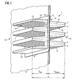
- FIG. 5 shows a prior art filter arrangement with a prior art filter cassette 1 mounted in an opening of a partition 6.
- the partition 6 shown here has the form of a wall. It separates a dirty air section at the upstream end 14 of the filter cassette from a clean air section at the downstream end 16 of the filter cassette 1.
- the filter cassette 1 is composed of a plurality of filter panels 2 having a V-bank arrangement extending in an upstream-to-downstream direction.
- the filter panels 2 are interconnected alternately at their upstream and downstream ends.
- the connection at the upstream end 14 is in the form of a mounting frame 8.
- the mounting frame 8 projects laterally so as to form a mounting face 5 on its downstream side.
- the mounting face 5 surrounds the filter panel package so that the filter cassette 1 can be mounted to the partition 6 via the mounting frame 8 in a substantially air tight manner wherein the mounting face 5 has a sealing function.
- air to be cleaned passes through the filter cassette 1, it enters the filter cassette 1 through the openings in the mounting frame 8, passes through the filter media 4 of the filter panels 2 from the upstream surface side 17 thereof to the downstream surface side 18 thereof and exits the filter cassette 1 from the filter cassette's downstream end 16.
- a typical prior art filter cassette would have a length of about 300 mm and would be designed to be mounted in openings of about 560 x 560 mm or 580 x 580 mm.
- Side walls 10 provide the strength necessary to maintain the desired V-bank arrangement of the filter panels 2 and force the air to be cleaned to pass through the filter panels 2.
- the filter cassette according to the present invention as hereinafter described in relation to a variety of embodiments differs from the prior art structure described above basically only in respect of the mounting frame and mounting face. Therefore, the same reference numerals are used hereinafter to describe the embodiments of the invention.
- FIG. 1 shows a first embodiment of a filter cassette 1 mounted in an opening 15 of a partitioning wall 6.
- two adjacent filter panels 2 form one V-bank.
- the filter panels of each V-bank are air tightly connected at the filter cassette's downstream end 16, e.g. by a suitable potting material.
- the filter panels 2 of two adjacent V-banks are air tightly connected at the filter cassette's upstream end 14, e.g. also by means of a suitable potting material.
- the mounting frame 8 is so connected to the filter panel package that its mounting face 5 by which the filter cassette 1 is mounted to a corresponding mounting face 13 of the partitioning wall 6 is positioned centrally between the upstream and downstream ends 14, 16 of the filter cassette 1, approximately in the barycenter line of the filter cassette.
- the mounting frame 8 not only stabilizes the filter panels 2, but also seals the filter panels 2 and their filter media 4 in a leakage free, i.e. air tight, manner.
- the filter panels 2 are further stabilized by top and bottom walls 19 made from a strong material, such as a metal or a stiff polymer material. Due to the position of the mounting face 5 approximately at the barycenter line of the overall filter cassette 1, torques induced by the filter cassette 1 into the partition wall 6 are minimized. Also, the upstream-to-downstream length of the filter panels 2 can be doubled from about 300 mm overall length of the filter cassette to about 600 mm overall length of the filter cassette, thereby increasing the filter surface area accordingly. This will improve the filter cassette's life cycle.
- the mounting face 5 centrally between the filter cassette's upstream and downstream ends 14, 16 with the distances Dup from the upstream end 14 and D down from the downstream end 16 being equal or substantially equal where the mounting face is positioned approximately at the barycenter line of the filter cassette.
- the aforementioned positive effects can already be achieved in part when the mounting face 5 is positioned only slightly towards the center of the filter cassette, as compared to prior art filter cassettes where the mounting frame 8 with its mounting face 5 is provided at the upstream (or downstream) end of the filter cassette.
- the mounting face 5 can be provided on the mounting frame's 8 upstream side in cases where the filter cassette is to be mounted into the partitioning wall's 6 opening 15 from the clean air section side or in a reverse arrangement.
- the mounting face 5 may be constituted by the mounting frame's surrounding side surface. In either case, the mounting face 5 has a sealing function and may include a gasket.
- the mounting frame 8 need not entirely surround the filter panel arrangement or the partitioning wall's opening 15.
- the mounting frame 8 may be provided only in certain sections, e.g. on the top and bottom sides of the filter cassette, where major torque forces can be expected.
- the side walls 10 are partly dispensed with both on the clean air section side of the filter cassette and on the dirty air section side of the filter cassette.
- Side walls 10 are only provided between adjacent panels in those areas where air flow must be blocked. More specifically, side walls 10 are provided in the dirty air section, i.e. upstream of the mounting frame 8, only between downstream surface sides 18 of adjacent filter panels 2 and in the clean air section, i.e. downstream of the mounting frame 8, only between upstream surface sides 17 of adjacent filter panels 2.
- the overall area for air to enter the filter cassette is thereby increased so that the velocity of entering air and, accordingly, flow resistance forces are decreased substantially. This has a beneficial effect on the pressure drop caused by the filter cassette in the air stream.
- the filter media 4 of the filter panels 2 is pleated in an upstream-to-downstream direction as depicted generally in Figures 1 and 6.
- the pleats itself are directed in this embodiment from the upstream end 14 to the downstream end 16 of the filter cassette. In other embodiments the pleats may extend from one side of the filter panel 2 to the opposite side thereof.
- the filter media 4 may comprise cellulose or glass fibers or synthetic materials such as polyester non-woven or polypropylene non-woven. It is particularly preferred to use a composite filter media having at least two superposed filtration layers, one of which preferably is a membrane filtration layer and the other a depth filtration layer.
- the depth filtration layer may comprise nano fibers or glass fibers, a non-woven fibrous polymeric web, such as a spun bond, a non-woven fabric, fiber glass, micro fiber glass, cellulose or polytetrafluoroethylene.
- the depth filtration layer is a melt blown web.
- the melt blown polymer fiber web layer or layers can be made from a variety of polymeric materials, including polypropylene, polyester, polyamide, polyvinylchloride, polymethylmethacrylate and polyethylene, among which polypropylene is the most preferred.
- the polymer fibers that form the web have a diameter in the range of about 0.05 ⁇ m to about 10 ⁇ m, preferably about 1 ⁇ m to about 5 ⁇ m.
- At least one depth filtration media is formed as an electret filter media comprising a highly efficient layer having an electrostatic charge. Electric charge is imparted to the melt blown fibers to improve their filtration performance using a variety of known techniques (see e.g. US patent no. 5,401,446 ). Downstream of the composite filter media's depth filtration layer or layers is disposed the membrane filtration layer which is intended to capture particles that pass through the depth filtration layer.
- a variety of microporous polymeric membranes can be used as the membrane filtration layer, depending on the requirements of the application.
- the membrane filtration layer may be constructed from the following exemplary materials: nitrocellulose, triacetyl cellulose, polyamide, polycarbonate, polyethylene, polypropylene, polytetrafluoroethylene, polysulfone, polyvinylidene fluoride, acrylate copolymer.
- the membrane filtration layer is preferably constructed from a hydrophobic material that is capable of preventing the passage of liquids. This is further explained in EP 1 674144 A1 and US 7,501,003 B.
- the membrane filtration layer is a microporous fluoropolymer, such as an expanded PTFE (ePTFE), fluorinated ethylene propylene (FEP), perfluoroalkoxy polymer (PFA), polypropylene (PP), polyethylene (PE) or ultrahigh molecular weight polyethylene (PE-UHMW).
- ePTFE expanded PTFE
- FEP fluorinated ethylene propylene
- PFA perfluoroalkoxy polymer
- PP polypropylene
- PE polyethylene
- PE-UHMW ultrahigh molecular weight polyethylene
- the overall size of the filter cassette in Figure 1 would typically amount to 592 mm x 592 mm or 610 mm x 610 mm frame size and about 600 mm overall length L.
- the filter frame may have a thickness of about 20 mm.
- three V-banks of filter panels 2 are arranged in the filter cassette.
- the surface area of the pleated filter media 4 in the filter cassette 1 can exceed 40 m 2 .
- the filter cassettes 1 are preferably used with a filter material providing class H12 particulate filtration efficiency (according to EN 1822) for an air stream of 4,250 m 3 /h or less.
- the air to cloth ratio is less than 3 cm/s and the lifetime exceeds 1 year for ambient air.
- Other characteristic values obtained with the filter cassette of the size described above are: wet burst pressure of over 6,200 Pa, whereas the initial pressure drop at an air flow of 4,250 m 3 /h is below 300 Pa.
- the pressure drop is less than 200 Pa, and where the side walls 10 are partially or substantially dispensed with and depending upon the overall length of the filter cassette, it can be further reduced to less than 180 Pa, 160 Pa, 140 Pa, 120 Pa and even less than 100 Pa.
- FIG 2 is a schematic cross sectional view of the filter cassette 1 of Figure 1 , but with only two V-banks, i.e. with four filter panels 2.
- the filter material 4 of the filter panels 4 is pleated such that the pleats extend from one panel side (not shown) to the opposite panel side (not shown) forming a zig-zag configuration of the filter material in said cross sectional view.
- the mounting frame 8 is attached to upper and lower mounting plates 19 to which the filter panels 2 are connected at their upstream ends.
- the mounting plates 19 do not have any filter function in this embodiment.
- Figure 3 shows a different embodiment in a view similar to Figure 2 .
- the two upper and lower mounting plates 19 are dispensed with and are replaced by filter panels 2.
- the amount of filter panel material is the same in both embodiments, but there is more opening area provided on the upstream side (dirty air section) for air to enter the filter cassette. That is, air to be filtered can enter the filter cassette from the upper and lower sides, which upper and lower sides are blocked by the mounting panels 19 in the first embodiment of Figures 1 and 2 . Accordingly, the pressure drop caused by a filter cassette according to the second embodiment of Figure 3 will be lower compared to a filter cassette according to the first embodiment under otherwise identical conditions.
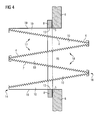
- Figure 4 shows an option for mounting the filter cassette 1 of Figures 1 and 2 with its mounting face 5 to a partitioning wall 6.
- Figure 4 shows the typical arrangement corresponding to the perspective view of Figure 1 , in which the filter panels 2 of the filter cassette 1 extend into the clean air section.
Abstract
Description
- The present invention relates to a filter cassette for removal of particles from an air stream and specifically refers to a filter arrangement comprising a partition with an opening in which the filter cassette is mounted. The invention particularly also relates to the use of the filter cassette for removing particles from a gas stream entering a gas turbine as well as to the gas turbine as such, as a specific application. However, the present invention may likewise be used in a variety of other applications, such as in emergency power generators, gas compressors, HVAC systems, gas mining operations where gas from salt stocks is unearthed, and the like.
- The aforementioned applications have in common that they require a large amount of air to be filtered with high particle filtration efficiency. While a single filter cassette has the capacity for filtering more than 1,000 m3 per hour, with a typical filter size of 592 mm x 592 mm x 300 mm or 610 mm x 610 mm x 300 mm filtering about 2,500 to 5,000 m3 per hour, a great number of filter cassettes are used in parallel in order to filter an amount of air of more than 10,000 m3 per hour or even more than 50,000 m3 per hour, and sometimes even much more than that. The filter cassette or cassettes are mounted in a partition separating an upstream volume generally referred to as the "dirty air section" and a downstream volume generally referred to as the "clean air section". The partition may be in the form of a wall with openings in which the filter cassettes are mounted or may be in the form of a rack defining a plurality of openings in which the filter cassettes are mounted so as to create a substantially airtight partition between the dirty air and clean air sections. In certain applications the great number of filter cassettes are provided in a filter house sufficiently large for operating staff to walk through and remove and replace individual filter cassettes when they are clogged or defective.
-
US 6,368,386 relates to an air filter system in an air intake stream of a gas turbine. Particulate material is filtered from the intake air at a first stage air cleaner and directed to a second stage air cleaner where moisture and, particularly, salt are removed from the intake air. The second stage air cleaner typically includes the aforementioned filter cassettes. Filter material that can advantageously be used as a filter media in the second stage air cleaner is described e.g. inEP 1 674 144 A1WO 2007/103408 ,EP 0 560 012 B1 andEP 0 723 800 B1 . Accordingly, the filter cassettes typically comprise a plurality of filter panels arranged so that pairs of panel filters form V-pockets extending from the filter cassette's upstream end to the filter cassette's downstream end. Each filter panel is composed of multiple pleats of filter media extending generally parallel to the overall filtration path, so that air or gas to be filtered passes through the pleats in a generally straight manner. The filter panels are mounted in a casing and are air tightly fitted in a mounting frame at the filter cassette's upstream end, or in a few applications at the filter cassette's downstream end. The mounting frame provides a mounting face for mounting the filter cassette to a corresponding mounting face of the partition so that the filter cassette extends into and through the opening of the partition into the clean air section. Staff can then easily remove and replace the filter cassette from the dirty air section side. - It is the object of the present invention to improve the known filter cassettes and filter arrangement, in particular in respect of filtering efficiency, lifetime, and pressure drop.
- Accordingly, the filter cassette of the present invention has an upstream end and a downstream end and comprises a mounting frame to which a filter media is fitted and which has a mounting face adapted for mounting the filter cassette to an opening of a partition, as described hereinbefore in relation to the prior art. According to the invention the mounting face is positioned between the filter cassette's upstream and downstream ends at a first distance from said upstream and a second distance from said downstream end, the first and second distances amounting to more than 10 percent of an overall length of the filter cassette. In particular, the first and second distances are at least 40 mm, more preferably 100 mm or more. This arrangement reduces inducement of torque from the filter cassette into the partition, which torque could lead to improper sealing pressure and could cause air to bypass the frame gasket. Also, torque exceeding the structural integrity of the partition can be prevented.
- In preferred embodiments the distance of the mounting face from the upstream and downstream ends of the filter cassette amounts to more than 15 percent of the overall length of the filter cassette, preferably more than 20 percent and even more preferably more than 25 percent. The absolute value of such distance is preferably 100 mm or more. Most preferably, the mounting face is positioned in a barycenter line of the filter cassette with respect to said upstream and downstream ends. Thus, assuming that the filter cassette has a symmetric structure, the mounting face is advantageously positioned centrally between said upstream and downstream ends.
- Another advantage achieved with the proposed structure is that the effective surface area of the filter media can be increased without increasing the length by which the filter cassette protrudes into the clean air section. That is, the filter cassette according to the invention instead extends partly into the dirty air section. This way, existing filter cassettes can be replaced with the proposed filter cassettes having a larger filter surface area, there being no need to adapt the partition or house in which the filter cassettes are mounted. As a result of the increased filter surface area, the filter lifetime will increase because less air will have to pass per partial area of the filter surface and because the air will pass through the filter media at a lower speed.
- The proposed arrangement of the mounting frame's mounting face at a position between the upstream and downstream ends of the filter cassette offers even further advantages when not only the mounting face but the entire mounting frame is positioned somewhere between the filter cassette's upstream and downstream ends. That is, the aforementioned advantages can generally be achieved with the mounting frame being provided at the filter cassette's upstream (or downstream) end and having a length in an upstream-to-downstream direction such that the mounting frame's mounting face is located e.g. at the filter cassette's barycenter line. However, it is particularly advantageous to provide the mounting frame in the area of the filter cassette where the filter cassette is to be mounted to the partition by means of the mounting face and air tightly seal the mounting frame to the filter panels in this area. The weight of the mounting frame and, thus, of the filter cassette is accordingly reduced. Also, torque induced from the filter panels to the filter frame is likewise reduced. Furthermore, side walls, that are provided upstream of the mounting frame between the filter panels, can be dispensed with between upstream surface sides of adjacent filter panels. The overall weight of the filter cassette is thereby further reduced and, more importantly, the pressure drop across the filter cassette is also substantially reduced. The differential pressure caused by the filter cassette when placed in an air stream is always one of the most critical characteristic values for a filter cassette. A pressure drop of 1,000 Pa can be equivalent to a power loss of the turbine of 1 to 3 percent. Since upstream of the mounting frame side walls are provided only between downstream surface sides of adjacent filter panels and not between the upstream surface sides, the opening area for the air to enter the filter cassette is increased as compared to the opening area of prior art filter cassettes not protruding into the dirty air section. Accordingly, the air to be filtered enters the filter cassette at reduced velocity. Altogether, this will result in a reduced pressure drop across the filter cassette and, thus, improve the performance of the turbine.
- Similarly, air flow resistance can be further reduced by providing side walls downstream of the mounting frame only between upstream surface sides of adjacent filter panels, so that the pressure drop across the filter cassette can be further improved. Most preferably, the two measures are combined in that upstream of the mounting frame side walls are provided only between downstream surface sides of adjacent filter panels whereas downstream of the mounting frame side walls are provided only between upstream surface sides of adjacent filter panels.
- While it has been described that side walls between filter panels can partly be dispensed with, it is further advantageous to form the top and bottom walls of the filter cassette from filter panels. In general, these walls of the filter cassette can be made from a strong material, such as metal or a stiff polymer material, in order to strengthen the overall structure of the filter cassette. However, when these walls are formed from the two outermost filter panels, they have a filtering function. This allows air to pass through the filter media of the filter cassette not only via the V-pockets from the front end and - where the side walls are partly dispensed with -sideways, but also directly through the two outermost filter panels, i.e. through the top and bottom walls of the filter cassette. The filter cassette's efficiency, lifetime and pressure drop are thereby further enhanced as compared to prior art filter cassettes.
- Using such filter cassettes with a filter media providing a particulate filtration efficiency at least of filter class H10, preferably H12 (according to EN 1822), a pressure drop of less than 200 Pa at an air flow of 3,400 cm3 per hour can be achieved. Depending on whether side walls are dispensed with at the upstream side, at the downstream side or at both the upstream and downstream sides, and depending on whether one or both of the two outermost filter panels are provided to have a filter function so that air can pass the filter media also from the top and bottom of the filter cassette, even better values of 180 Pa, 160 Pa, 140 Pa, 120 Pa and even less than 100 Pa can be obtained.
- Of course, the pressure drop largely depends upon the material used as the filter media. The material described in
EP 1 674 144 A1 - Thus, a filter cassette according to a preferred embodiment of the invention has an upstream end and a downstream end and comprises a mounting frame to which a filter media is fitted and which has a mounting face adapted for mounting the filter cassette to an opening of a partition, wherein said mounting face is positioned between the filter cassette's upstream and downstream ends at a first distance from said upstream end and a second distance from said downstream end, each of said first and second distances amounting to more than 10% of an overall length of the filter cassette, wherein the first and second distances are at least 40 mm.
- A filter cassette according to another preferred embodiment of the invention has an upstream end and a downstream end and comprises a mounting frame to which a filter media is fitted and which has a mounting face adapted for mounting the filter cassette to an opening of a partition, wherein said mounting face is positioned between the filter cassette's upstream and downstream ends at a first distance from said upstream end and a second distance from said downstream end, wherein said first and second distances each amount to more than 25% of the overall length.
- A filter cassette according to an even further preferred embodiment of the invention has an upstream end and a downstream end and comprises a mounting frame to which a filter media is fitted and which has a mounting face adapted for mounting the filter cassette to an opening of a partition, wherein said mounting face is positioned between the filter cassette's upstream and downstream ends at a first distance from said upstream end and a second distance from said downstream end, each of said first and second distances amounting to more than 10% of an overall length of the filter cassette, wherein said filter media comprises a plurality of filter panels extending in an upstream-to-downstream direction, wherein said filter panels are interconnected alternately at their upstream and downstream ends and side walls connecting adjacent filter panels are provided so that fluid passing through the filter cassette is forced to pass through said filter panels.
- The filter cassette of the above-described types can advantageously be used to remove particles from a gas stream entering a high-capacity gas turbine. A single filter cassette may have an air flow capacity of between 500 and 6,000 m3 per hour and a plurality of filter cassettes can be used in parallel to filter 1,000 m3 per hour or 4,000 m3 per hour or even more than 10,000 m3 per hour.
-
-
Figure 1 is a perspective side view of a filter cassette according to the present invention, -
Figure 2 is a schematic cross sectional view through a filter cassette similar to the one shown inFigure 1 according to a first embodiment, -
Figure 3 is a schematic cross sectional view through a filter cassette similar to the one shown inFigure 1 according to a second embodiment, -
Figure 4 is a schematic cross sectional view through a filter cassette similar to the one shown inFigure 1 according to a third embodiment, and -
Figure 5 shows a filter arrangement of a prior art filter cassette. -
Figure 5 shows a prior art filter arrangement with a priorart filter cassette 1 mounted in an opening of apartition 6. Thepartition 6 shown here has the form of a wall. It separates a dirty air section at theupstream end 14 of the filter cassette from a clean air section at thedownstream end 16 of thefilter cassette 1. Thefilter cassette 1 is composed of a plurality offilter panels 2 having a V-bank arrangement extending in an upstream-to-downstream direction. Thefilter panels 2 are interconnected alternately at their upstream and downstream ends. The connection at theupstream end 14 is in the form of a mountingframe 8. The mountingframe 8 projects laterally so as to form a mountingface 5 on its downstream side. The mountingface 5 surrounds the filter panel package so that thefilter cassette 1 can be mounted to thepartition 6 via the mountingframe 8 in a substantially air tight manner wherein the mountingface 5 has a sealing function. When air to be cleaned passes through thefilter cassette 1, it enters thefilter cassette 1 through the openings in the mountingframe 8, passes through thefilter media 4 of thefilter panels 2 from theupstream surface side 17 thereof to thedownstream surface side 18 thereof and exits thefilter cassette 1 from the filter cassette'sdownstream end 16. A typical prior art filter cassette would have a length of about 300 mm and would be designed to be mounted in openings of about 560 x 560 mm or 580 x 580 mm. -
Side walls 10 provide the strength necessary to maintain the desired V-bank arrangement of thefilter panels 2 and force the air to be cleaned to pass through thefilter panels 2. - The filter cassette according to the present invention as hereinafter described in relation to a variety of embodiments differs from the prior art structure described above basically only in respect of the mounting frame and mounting face. Therefore, the same reference numerals are used hereinafter to describe the embodiments of the invention.
-
Figure 1 shows a first embodiment of afilter cassette 1 mounted in anopening 15 of apartitioning wall 6. As in the prior art, twoadjacent filter panels 2 form one V-bank. The filter panels of each V-bank are air tightly connected at the filter cassette'sdownstream end 16, e.g. by a suitable potting material. Similarly, thefilter panels 2 of two adjacent V-banks are air tightly connected at the filter cassette'supstream end 14, e.g. also by means of a suitable potting material. The mountingframe 8 is so connected to the filter panel package that its mountingface 5 by which thefilter cassette 1 is mounted to a corresponding mountingface 13 of thepartitioning wall 6 is positioned centrally between the upstream and downstream ends 14, 16 of thefilter cassette 1, approximately in the barycenter line of the filter cassette. Therefore, as in the prior art filter cassette, air to be filtered will pass through the upstream surface sides 17 of the filter panel's 2filter media 4 on the dirty air section side of thefilter cassette 1 and exit thefilter media 4 on the filter panel's 2downstream surface side 18 into the clean air section. - The mounting
frame 8 not only stabilizes thefilter panels 2, but also seals thefilter panels 2 and theirfilter media 4 in a leakage free, i.e. air tight, manner. Thefilter panels 2 are further stabilized by top andbottom walls 19 made from a strong material, such as a metal or a stiff polymer material. Due to the position of the mountingface 5 approximately at the barycenter line of theoverall filter cassette 1, torques induced by thefilter cassette 1 into thepartition wall 6 are minimized. Also, the upstream-to-downstream length of thefilter panels 2 can be doubled from about 300 mm overall length of the filter cassette to about 600 mm overall length of the filter cassette, thereby increasing the filter surface area accordingly. This will improve the filter cassette's life cycle. - It is most preferable to position the mounting
face 5 centrally between the filter cassette's upstream and downstream ends 14, 16 with the distances Dup from theupstream end 14 and Ddown from thedownstream end 16 being equal or substantially equal where the mounting face is positioned approximately at the barycenter line of the filter cassette. However, the aforementioned positive effects can already be achieved in part when the mountingface 5 is positioned only slightly towards the center of the filter cassette, as compared to prior art filter cassettes where the mountingframe 8 with its mountingface 5 is provided at the upstream (or downstream) end of the filter cassette. It should also be mentioned here that, unlike the embodiment shown inFigure 1 , the mountingface 5 can be provided on the mounting frame's 8 upstream side in cases where the filter cassette is to be mounted into the partitioning wall's 6opening 15 from the clean air section side or in a reverse arrangement. Alternatively, where the mountingframe 8 exactly fits in theopening 15, the mountingface 5 may be constituted by the mounting frame's surrounding side surface. In either case, the mountingface 5 has a sealing function and may include a gasket. - It should further be noted that, although this is preferable, the mounting
frame 8 need not entirely surround the filter panel arrangement or the partitioning wall'sopening 15. For instance, if there is otherwise provided a tight fit between the filter panel arrangement and the partitioning wall'sopening 15, the mountingframe 8 may be provided only in certain sections, e.g. on the top and bottom sides of the filter cassette, where major torque forces can be expected. - It can further be seen in
Figure 1 that theside walls 10 are partly dispensed with both on the clean air section side of the filter cassette and on the dirty air section side of the filter cassette.Side walls 10 are only provided between adjacent panels in those areas where air flow must be blocked. More specifically,side walls 10 are provided in the dirty air section, i.e. upstream of the mountingframe 8, only between downstream surface sides 18 ofadjacent filter panels 2 and in the clean air section, i.e. downstream of the mountingframe 8, only between upstream surface sides 17 ofadjacent filter panels 2. The overall area for air to enter the filter cassette is thereby increased so that the velocity of entering air and, accordingly, flow resistance forces are decreased substantially. This has a beneficial effect on the pressure drop caused by the filter cassette in the air stream. Thus, two effects come together: by increasing the length of the filter panels and thus the effective surface area of the filter panels the velocity of the air passing through the filter panels is substantially reduced, and by increasing the cross sectional area for the air to enter the filter cassette due to the partial lack of side walls the air flow velocity is also reduced. - The
filter media 4 of thefilter panels 2 is pleated in an upstream-to-downstream direction as depicted generally inFigures 1 and 6. The pleats itself are directed in this embodiment from theupstream end 14 to thedownstream end 16 of the filter cassette. In other embodiments the pleats may extend from one side of thefilter panel 2 to the opposite side thereof. Thefilter media 4 may comprise cellulose or glass fibers or synthetic materials such as polyester non-woven or polypropylene non-woven. It is particularly preferred to use a composite filter media having at least two superposed filtration layers, one of which preferably is a membrane filtration layer and the other a depth filtration layer. The depth filtration layer may comprise nano fibers or glass fibers, a non-woven fibrous polymeric web, such as a spun bond, a non-woven fabric, fiber glass, micro fiber glass, cellulose or polytetrafluoroethylene. Preferably the depth filtration layer is a melt blown web. The melt blown polymer fiber web layer or layers can be made from a variety of polymeric materials, including polypropylene, polyester, polyamide, polyvinylchloride, polymethylmethacrylate and polyethylene, among which polypropylene is the most preferred. Typically, the polymer fibers that form the web have a diameter in the range of about 0.05 µm to about 10 µm, preferably about 1 µm to about 5 µm. - Preferably, at least one depth filtration media is formed as an electret filter media comprising a highly efficient layer having an electrostatic charge. Electric charge is imparted to the melt blown fibers to improve their filtration performance using a variety of known techniques (see e.g.
US patent no. 5,401,446 ). Downstream of the composite filter media's depth filtration layer or layers is disposed the membrane filtration layer which is intended to capture particles that pass through the depth filtration layer. A variety of microporous polymeric membranes can be used as the membrane filtration layer, depending on the requirements of the application. The membrane filtration layer may be constructed from the following exemplary materials: nitrocellulose, triacetyl cellulose, polyamide, polycarbonate, polyethylene, polypropylene, polytetrafluoroethylene, polysulfone, polyvinylidene fluoride, acrylate copolymer. The membrane filtration layer is preferably constructed from a hydrophobic material that is capable of preventing the passage of liquids. This is further explained inEP 1 674144 A1US 7,501,003 B. Preferably, the membrane filtration layer is a microporous fluoropolymer, such as an expanded PTFE (ePTFE), fluorinated ethylene propylene (FEP), perfluoroalkoxy polymer (PFA), polypropylene (PP), polyethylene (PE) or ultrahigh molecular weight polyethylene (PE-UHMW). Particularly suitable ePTFE membranes are described inUS 5,814,405 . For further information on suitable materials, their properties and corresponding test methods reference is made toEP 1 674 144 A1 - The overall size of the filter cassette in
Figure 1 would typically amount to 592 mm x 592 mm or 610 mm x 610 mm frame size and about 600 mm overall length L. The filter frame may have a thickness of about 20 mm. Typically, three V-banks offilter panels 2 are arranged in the filter cassette. The surface area of thepleated filter media 4 in thefilter cassette 1 can exceed 40 m2. - The
filter cassettes 1 are preferably used with a filter material providing class H12 particulate filtration efficiency (according to EN 1822) for an air stream of 4,250 m3/h or less. The air to cloth ratio is less than 3 cm/s and the lifetime exceeds 1 year for ambient air. Other characteristic values obtained with the filter cassette of the size described above are: wet burst pressure of over 6,200 Pa, whereas the initial pressure drop at an air flow of 4,250 m3/h is below 300 Pa. At an air flow of 3,400 m3/h, the pressure drop is less than 200 Pa, and where theside walls 10 are partially or substantially dispensed with and depending upon the overall length of the filter cassette, it can be further reduced to less than 180 Pa, 160 Pa, 140 Pa, 120 Pa and even less than 100 Pa. -
Figure 2 is a schematic cross sectional view of thefilter cassette 1 ofFigure 1 , but with only two V-banks, i.e. with fourfilter panels 2. Thefilter material 4 of thefilter panels 4 is pleated such that the pleats extend from one panel side (not shown) to the opposite panel side (not shown) forming a zig-zag configuration of the filter material in said cross sectional view. As can be seen, the mountingframe 8 is attached to upper and lower mountingplates 19 to which thefilter panels 2 are connected at their upstream ends. The mountingplates 19 do not have any filter function in this embodiment. -
Figure 3 shows a different embodiment in a view similar toFigure 2 . In this embodiment, the two upper and lower mountingplates 19 are dispensed with and are replaced byfilter panels 2. As can be seen by a comparison of the embodiments inFigures 2 and3 , the amount of filter panel material is the same in both embodiments, but there is more opening area provided on the upstream side (dirty air section) for air to enter the filter cassette. That is, air to be filtered can enter the filter cassette from the upper and lower sides, which upper and lower sides are blocked by the mountingpanels 19 in the first embodiment ofFigures 1 and2 . Accordingly, the pressure drop caused by a filter cassette according to the second embodiment ofFigure 3 will be lower compared to a filter cassette according to the first embodiment under otherwise identical conditions. -
Figure 4 shows an option for mounting thefilter cassette 1 ofFigures 1 and2 with its mountingface 5 to apartitioning wall 6.Figure 4 shows the typical arrangement corresponding to the perspective view ofFigure 1 , in which thefilter panels 2 of thefilter cassette 1 extend into the clean air section. -
- 1. A filter cassette (1) for removal of particles from an air stream, said filter cassette having an upstream end (14) and a downstream end (16) and comprising a mounting frame (8) to which a filter media (4) is fitted and which has a mounting face (5) adapted for mounting the filter cassette to an opening of a partition (6), wherein said mounting face (5) is positioned between the filter cassette's upstream and downstream ends (14, 16) at a first distance (Dup) from said upstream end (14) and a second distance (Ddown) from said downstream end (16), each of said first and second distances (Dup, Ddown) amounting to more than 10% of an overall length (L) of the filter cassette.
- 2. The filter cassette (1) of
para 1, wherein said first and second distances (Dup, Ddown) are at least 40 mm, more preferably 100 mm or more. - 3. The filter cassette (1) of
para - 4. The filter cassette (1) of
para - 5. The filter cassette (1) of any of
paras 1 to 4, wherein said mounting face (5) is positioned in a barycenter line of the filter cassette with respect to said upstream and downstream ends (14, 16). - 6. The filter cassette (1) of any of
paras 1 to 5, wherein said filter media (4) comprises a plurality of filter panels (2) extending in an upstream-to-downstream direction, wherein said filter panels (2) are interconnected alternately at their upstream and downstream ends (14,16) and side walls (10) connecting adjacent filter panels (2) are provided so that fluid passing through the filter cassette is forced to pass through said filter panels. - 7. The filter cassette (1) of
para 6, wherein said filter media (4) is pleated in an upstream-to-downstream direction. - 8. The filter cassette (1) of
para 6 or 7, wherein said mounting frame (8) is connected to said filter panels (2) in an area of the filter cassette (1) where the filter cassette is to be mounted to said partition (6) by means of said mounting face (5). - 9. The filter cassette (1) of
para 8, wherein upstream of said mounting frame (8) said side walls (10) are provided only between downstream surface sides (18) of adjacent filter panels (2). - 10. The filter cassette (1) of
para 8 or 9, wherein downstream of said mounting frame (8) said side walls (10) are provided only between upstream surface sides (17) of adjacent filter panels (2). - 11. The filter cassette (1) of
para 8, wherein upstream of said mounting frame (8) said side walls (10) are provided only between downstream surface sides (18) of adjacent filter panels (2) and downstream of said mounting frame (8) said side walls (10) are provided only between upstream surface sides (17) of adjacent filter panels (2). - 12. The filter cassette (1) of any of
paras 8 to 11, wherein the two outermost filter panels extend from said upstream and/or downstream ends (14,16) to said mounting face (5) and have a filter function. - 13. The filter cassette (1) of any of
paras 1 to 12, wherein said overall length of the filter cassette is equal to or greater than 250 mm. - 14. The filter cassette (1) of any of
paras 1 to 13, wherein said mounting face (5) has a sealing function. - 15. The filter cassette (1) of any of
paras 1 to 14, wherein the filter media (4) has a particulate filtration efficiency of at least filter class H10, preferably filter class H12, according to EN 1822, the filter cassette providing a pressure drop of less than 200 Pa at an air flow of 3,400 m3 per hour. - 16. The filter cassette (1) of
para 15, wherein the pressure drop at an air flow of 3,400 m3 per hour is less than 180 Pa, preferably less than 160 Pa, more preferably less than 140 Pa, even more preferably less than 120 Pa, most preferably less than 100 Pa. - 17. The filter cassette (1) of any of
paras 1 to 16, wherein the filter media (4) comprises one or more of the following filter layers: glass fiber filter layer, synthetic fiber filter layer, e.g. made from non-woven polyester or non-woven polypropylene, cellulose filter layer. - 18. The filter cassette (1) of any of
paras 1 to 17, wherein the filter media (4) is a composite material comprising a plurality of adjacent filter layers, preferably including one or more of the following filter layers: at least one ePTFE membrane, at least one layer of nano fibers, at least one layer of glass fibers, and an electrostatically charged non-woven layer. - 19. A filter arrangement comprising a partition (6) having an opening (15) and a mounting face (13) surrounding said opening (15), wherein a filter cassette (1) of any of
paras 1 to 18 is mounted to said partition mounting face (13) so that said filter media (4) of the filter cassette projects to both sides of said partition mounting face (13). - 20. A gas turbine, comprising one or more than one filter cassette (1) of any of
paras 1 to 18 arranged for removing particles from a gas stream entering the gas turbine. - 21. The gas turbine of para 20, having an air flow capacity of at least 1,000 m3 per hour, preferably more than 4,000 m3 per hour, more preferably more than 10,000 m3 per hour.
- 22. The gas turbine of para 20 or 21, wherein at least one filter cassette (1) has an air flow capacity between 500 and 6,000 m3 per hour.
- 23. Use of the filter cassette (1) of any of
paras 1 to 18 for removing particles from a gas stream entering a gas turbine. - 24. Use of the filter cassette (1) according to para 23 in an air intake of a gas turbine having an air flow capacity of at least 1,000 m3 per hour, preferably more than 4,000 m3 per hour, more preferably more than 10,000 m3 per hour.
Claims (19)
- A filter cassette (1) for removal of particles from an air stream, said filter cassette having an upstream end (14) and a downstream end (16) and comprising a mounting frame (8) to which a filter media (4) is fitted and which has a mounting face (5) adapted for mounting the filter cassette to an opening of a partition (6), wherein said mounting face (5) is positioned between the filter cassette's upstream and downstream ends (14, 16) at a first distance (Dup) from said upstream end (14) and a second distance (Ddown) from said downstream end (16), each of said first and second distances (Dup, Ddown) amounting to more than 10% of an overall length (L) of the filter cassette.
- The filter cassette (1) of claim 1, wherein said first and second distances (Dup, Ddown) are at least 40 mm, more preferably 100 mm or more.
- The filter cassette (1) of claim 1 or 2, wherein said first and second distances (Dup, Ddown) each amount to more than 25%.
- The filter cassette (1) of claim 1 or 2, wherein said mounting face (5) is positioned centrally between said upstream and downstream ends (14, 16) with respect to said overall length (L) of the filter cassette.
- The filter cassette (1) of any of claims 1 to 4, wherein said mounting face (5) is positioned in a barycenter line of the filter cassette with respect to said upstream and downstream ends (14,16).
- The filter cassette (1) of any of claims 1 to 5, wherein said filter media (4) comprises a plurality of filter panels (2) extending in an upstream-to-downstream direction, wherein said filter panels (2) are interconnected alternately at their upstream and downstream ends (14, 16) and side walls (10) connecting adjacent filter panels (2) are provided so that fluid passing through the filter cassette is forced to pass through said filter panels.
- The filter cassette (1) of claim 6, wherein said mounting frame (8) is connected to said filter panels (2) in an area of the filter cassette (1) where the filter cassette is to be mounted to said partition (6) by means of said mounting face (5).
- The filter cassette (1) of claim 7, wherein upstream of said mounting frame (8) said side walls (10) are provided only between downstream surface sides (18) of adjacent filter panels (2).
- The filter cassette (1) of claim 7 or 8, wherein downstream of said mounting frame (8) said side walls (10) are provided only between upstream surface sides (17) of adjacent filter panels (2).
- The filter cassette (1) of claim 7, wherein upstream of said mounting frame (8) said side walls (10) are provided only between downstream surface sides (18) of adjacent filter panels (2) and downstream of said mounting frame (8) said side walls (10) are provided only between upstream surface sides (17) of adjacent filter panels (2).
- The filter cassette (1) of any of claims 7 to 10, wherein the two outermost filter panels extend from said upstream and/or downstream ends (14, 16) to said mounting face (5) and have a filter function.
- The filter cassette (1) of any of claims 1 to 11, wherein the filter media (4) has a particulate filtration efficiency of at least filter class H10, preferably filter class H12, according to EN 1822, the filter cassette providing a pressure drop of less than 200 Pa at an air flow of 3,400 m3 per hour.
- The filter cassette (1) of claim 12, wherein the pressure drop at an air flow of 3,400 m3 per hour is less than 180 Pa, preferably less than 160 Pa, more preferably less than 140 Pa, even more preferably less than 120 Pa, most preferably less than 100 Pa.
- A filter arrangement comprising a partition (6) having an opening (15) and a mounting face (13) surrounding said opening (15), wherein a filter cassette (1) of any of claims 1 to 13 is mounted to said partition mounting face (13) so that said filter media (4) of the filter cassette projects to both sides of said partition mounting face (13).
- A gas turbine, comprising one or more than one filter cassette (1) of any of claims 1 to 13 arranged for removing particles from a gas stream entering the gas turbine.
- The gas turbine of claim 15, having an air flow capacity of at least 1,000 m3 per hour, preferably more than 4,000 m3 per hour, more preferably more than 10,000 m3 per hour.
- The gas turbine of claim 15 or 16, wherein at least one filter cassette (1) has an air flow capacity between 500 and 6,000 m3 per hour.
- Use of the filter cassette (1) of any of claims 1 to 13 for removing particles from a gas stream entering a gas turbine.
- Use of the filter cassette (1) according to claim 18 in an air intake of a gas turbine having an air flow capacity of at least 1,000 m3 per hour, preferably more than 4,000 m3 per hour, more preferably more than 10,000 m3 per hour.
Priority Applications (12)
| Application Number | Priority Date | Filing Date | Title |
|---|---|---|---|
| ES09004899T ES2384910T3 (en) | 2009-04-02 | 2009-04-02 | Filtering cassette, filtering device and gas turbine with said filtering cassette |
| EP09004899A EP2246106B1 (en) | 2009-04-02 | 2009-04-02 | Filter cassette, filter arrangement, and gas turbine with such filter cassette |
| JP2012502659A JP5592471B2 (en) | 2009-04-02 | 2010-03-31 | Filter cassette, filter arrangement structure and gas turbine equipped with such a filter cassette |
| US13/260,934 US8870994B2 (en) | 2009-04-02 | 2010-03-31 | Filter cassette, filter arrangement, and gas turbine with such filter cassette |
| PCT/EP2010/054279 WO2010112542A1 (en) | 2009-04-02 | 2010-03-31 | Filter cassette, filter arrangement, and gas turbine with such filter cassette |
| CN201080013994.0A CN102365120B (en) | 2009-04-02 | 2010-03-31 | Filter cassette, filter arrangement, and gas turbine with such filter cassette |
| KR1020117025952A KR101431887B1 (en) | 2009-04-02 | 2010-03-31 | Filter cassette, filter arrangement, and gas turbine with such filter cassette |
| RU2011144376/05A RU2491114C2 (en) | 2009-04-02 | 2010-03-31 | Cassette filter, filtration device and gas turbine with such cassette filter |
| AU2010230161A AU2010230161B2 (en) | 2009-04-02 | 2010-03-31 | Filter cassette, filter arrangement, and gas turbine with such filter cassette |
| CA2756512A CA2756512C (en) | 2009-04-02 | 2010-03-31 | Filter cassette, filter arrangement, and gas turbine with such filter cassette |
| BRPI1014782A BRPI1014782A2 (en) | 2009-04-02 | 2010-03-31 | filter cassette and filter unit and gas turbine with said filter cassette |
| HK12107577.2A HK1166748A1 (en) | 2009-04-02 | 2012-08-01 | Filter cassette, filter arrangement, and gas turbine with such filter cassette |
Applications Claiming Priority (1)
| Application Number | Priority Date | Filing Date | Title |
|---|---|---|---|
| EP09004899A EP2246106B1 (en) | 2009-04-02 | 2009-04-02 | Filter cassette, filter arrangement, and gas turbine with such filter cassette |
Publications (2)
| Publication Number | Publication Date |
|---|---|
| EP2246106A1 true EP2246106A1 (en) | 2010-11-03 |
| EP2246106B1 EP2246106B1 (en) | 2012-06-20 |
Family
ID=41061090
Family Applications (1)
| Application Number | Title | Priority Date | Filing Date |
|---|---|---|---|
| EP09004899A Active EP2246106B1 (en) | 2009-04-02 | 2009-04-02 | Filter cassette, filter arrangement, and gas turbine with such filter cassette |
Country Status (12)
| Country | Link |
|---|---|
| US (1) | US8870994B2 (en) |
| EP (1) | EP2246106B1 (en) |
| JP (1) | JP5592471B2 (en) |
| KR (1) | KR101431887B1 (en) |
| CN (1) | CN102365120B (en) |
| AU (1) | AU2010230161B2 (en) |
| BR (1) | BRPI1014782A2 (en) |
| CA (1) | CA2756512C (en) |
| ES (1) | ES2384910T3 (en) |
| HK (1) | HK1166748A1 (en) |
| RU (1) | RU2491114C2 (en) |
| WO (1) | WO2010112542A1 (en) |
Cited By (2)
| Publication number | Priority date | Publication date | Assignee | Title |
|---|---|---|---|---|
| WO2014195796A1 (en) * | 2013-06-04 | 2014-12-11 | Torsten Herrmann | Filtration system and method for cleaning the intake air of a gas turbine |
| RU2675917C2 (en) * | 2014-05-27 | 2018-12-25 | Торстен ХЕРРМАНН | Filtration system and method of cleaning incoming air of gas turbine |
Families Citing this family (15)
| Publication number | Priority date | Publication date | Assignee | Title |
|---|---|---|---|---|
| US8590158B2 (en) | 2010-10-29 | 2013-11-26 | Corning Incorporated | Methods of making filter apparatus and fabricating a porous ceramic article |
| US8591622B2 (en) | 2010-10-29 | 2013-11-26 | Corning Incorporated | Filter apparatus with porous ceramic plates |
| US20130011249A1 (en) * | 2011-07-08 | 2013-01-10 | General Electric Company | Multi-layer filter, gas turbine including a multi-layer filter, and process of filtering |
| EP2840115B1 (en) | 2012-04-20 | 2018-06-06 | Daikin Industries, Ltd. | Composition mainly composed of ptfe, mixed powder, molding material, filtering medium for filter, air filter unit, and porous membrane manufacturing method |
| US9205359B2 (en) * | 2012-10-09 | 2015-12-08 | W.L. Gore & Associates, Inc. | V-panel filters |
| US9028578B2 (en) * | 2013-02-28 | 2015-05-12 | Bha Altair, Llc | Gas turbine inlet filter with replaceable media cartridges |
| DK2772293T3 (en) * | 2013-03-01 | 2020-08-24 | Gore & Ass | Substance filter system and method for regenerating a substance filter |
| JP5595610B1 (en) * | 2014-01-29 | 2014-09-24 | パナソニック株式会社 | Image forming apparatus |
| US10502136B2 (en) * | 2014-10-06 | 2019-12-10 | Bha Altair, Llc | Filtration system for use in a gas turbine engine assembly and method of assembling thereof |
| US20170056800A1 (en) * | 2015-05-05 | 2017-03-02 | Airgle Corporation | Filter assembly for providing purified air |
| US10967317B2 (en) * | 2015-08-18 | 2021-04-06 | W. L. Gore & Associates, Inc. | Filter assembly with curved inlet guide |
| CN108201752B (en) * | 2016-12-16 | 2023-07-14 | 上海通周机械设备工程有限公司 | Multi-layer filter paper type filter box |
| CN108554025A (en) * | 2018-06-25 | 2018-09-21 | 中山尚诚环保科技有限公司 | A kind of easy-to-dismount filter device |
| CN112654409B (en) * | 2018-09-11 | 2024-03-29 | 曼·胡默尔有限公司 | Filter element having a receiving chamber containing a desiccant and fluid filter |
| RU204000U1 (en) * | 2021-02-19 | 2021-05-04 | Сергей Владимирович Винокуров | DEVICE FOR CONNECTING A PLASTIC AIR TREATMENT UNIT WITH A INLET IN A METAL AIR DUCT OF A GAS PUMPING UNIT |
Citations (10)
| Publication number | Priority date | Publication date | Assignee | Title |
|---|---|---|---|---|
| EP0479114A1 (en) * | 1990-10-04 | 1992-04-08 | Luwa Aktiengesellschaft | Folded filter unit |
| US5401446A (en) | 1992-10-09 | 1995-03-28 | The University Of Tennessee Research Corporation | Method and apparatus for the electrostatic charging of a web or film |
| EP0560012B1 (en) | 1992-02-13 | 1997-03-26 | EMW-BETRIEBE EMMERLING & WEYL GmbH & CO. SCHAUMSTOFF KG | Cassette filter |
| US5814405A (en) | 1995-08-04 | 1998-09-29 | W. L. Gore & Associates, Inc. | Strong, air permeable membranes of polytetrafluoroethylene |
| EP0723800B1 (en) | 1995-01-26 | 2001-02-21 | Firma Carl Freudenberg | Cassette filter |
| US6368386B1 (en) | 1998-06-09 | 2002-04-09 | Donaldson Company, Inc. | Filter construction resistant to the passage of water soluble materials; and method |
| EP1447121A1 (en) * | 2001-11-21 | 2004-08-18 | Mitsubishi Heavy Industries, Ltd. | Dust collecting filter, dust collecting device, and intake device of gas turbine |
| EP1674144A1 (en) | 2004-12-23 | 2006-06-28 | W.L. GORE & ASSOCIATES GmbH | Turbine air-intake filter |
| US20070209343A1 (en) * | 2006-03-09 | 2007-09-13 | Leon Robert Cuvelier | Filter assembly with pleated media pockets, and methods |
| US7501003B2 (en) | 2004-03-02 | 2009-03-10 | Gore Enterprise Holdings | Composite filter media |
Family Cites Families (19)
| Publication number | Priority date | Publication date | Assignee | Title |
|---|---|---|---|---|
| DE2751640A1 (en) * | 1977-11-17 | 1979-05-23 | Delbag Luftfilter Gmbh | REPLACEABLE FILTER ELEMENT, IN PARTICULAR FOR NUCLEAR SYSTEMS, FOR CLEANING AIR OR GAS FLOWS LOADED WITH TOXIC OR RADIOACTIVE COMPONENTS AND PROCEDURES FOR REPLACING AND REMOVING VOLUME FILTER REMOVAL |
| JPH0326903Y2 (en) * | 1986-10-01 | 1991-06-11 | ||
| EP0663228B1 (en) * | 1994-01-15 | 2000-08-09 | Filtrair B.V. | Filter element for the separation of dust particles from a gas |
| JP3486649B2 (en) * | 1994-01-17 | 2004-01-13 | 日本バイリーン株式会社 | Flanged filter, filter frame, and mounting structure of flanged filter to filter frame |
| US5512074A (en) * | 1994-09-19 | 1996-04-30 | Farr Company | Air filter assembly |
| EP0707139B1 (en) * | 1994-10-13 | 2000-01-19 | Sumitomo Electric Industries, Ltd. | Particulate trap |
| US5788726A (en) * | 1996-06-13 | 1998-08-04 | Dynamic Air, Inc. | In chamber system protectors |
| US20030226792A1 (en) * | 1998-11-26 | 2003-12-11 | Filterwerk Mann & Hummel Gmbh | Multilayer filter element |
| US6485538B1 (en) * | 1999-03-31 | 2002-11-26 | Yugen Caisha Infinity Kenkyusho | Air-conditioning air filter |
| FR2806319B1 (en) * | 2000-03-15 | 2002-10-25 | Valeo | FILTRATION DEVICE FOR FITTING A VENTILATION AND / OR HEATING AND / OR AIR CONDITIONING APPARATUS, PARTICULARLY FOR A MOTOR VEHICLE |
| US6447566B1 (en) * | 2000-06-21 | 2002-09-10 | Freudenberg Nonwovens Limited Partnership | Air filtration system with recessed filter and edge banding |
| JP2002201963A (en) * | 2000-12-28 | 2002-07-19 | Mitsubishi Heavy Ind Ltd | Filter for gas turbine air intake part and gas turbine |
| DE10221779A1 (en) * | 2002-05-15 | 2003-11-27 | Freudenberg Carl Kg | Filter installation comprises numerous filters arranged one behind other and held by frames which are joined together by connection elements |
| RU2238135C2 (en) * | 2002-10-31 | 2004-10-20 | Федеральное государственное унитарное предприятие "Сибирский химический комбинат" Министерства Российской Федерации по атомной энергии | Filter for cleaning gaseous medium |
| US6955696B1 (en) * | 2003-07-31 | 2005-10-18 | Filtration Group, Inc. | Filter frame and assembly |
| US20080017038A1 (en) * | 2006-07-21 | 2008-01-24 | 3M Innovative Properties Company | High efficiency hvac filter |
| US20080105123A1 (en) * | 2006-11-02 | 2008-05-08 | General Electric Company | Gas turbine air filter |
| RU79802U1 (en) * | 2008-09-01 | 2009-01-20 | Общество с ограниченной ответственностью "Научно-исследовательский институт природных газов и газовых технологий-ВНИИГАЗ" (ООО "ВНИИГАЗ") | COMBINED FILTRATION SYSTEM |
| FR2944050B1 (en) * | 2009-04-02 | 2014-07-11 | Turbomeca | DISCHARGED BLADE TURBINE WHEEL COMPRISING A DAMPING DEVICE |
-
2009
- 2009-04-02 EP EP09004899A patent/EP2246106B1/en active Active
- 2009-04-02 ES ES09004899T patent/ES2384910T3/en active Active
-
2010
- 2010-03-31 US US13/260,934 patent/US8870994B2/en active Active
- 2010-03-31 JP JP2012502659A patent/JP5592471B2/en not_active Expired - Fee Related
- 2010-03-31 CN CN201080013994.0A patent/CN102365120B/en not_active Expired - Fee Related
- 2010-03-31 AU AU2010230161A patent/AU2010230161B2/en not_active Ceased
- 2010-03-31 RU RU2011144376/05A patent/RU2491114C2/en not_active IP Right Cessation
- 2010-03-31 CA CA2756512A patent/CA2756512C/en not_active Expired - Fee Related
- 2010-03-31 WO PCT/EP2010/054279 patent/WO2010112542A1/en active Application Filing
- 2010-03-31 BR BRPI1014782A patent/BRPI1014782A2/en not_active IP Right Cessation
- 2010-03-31 KR KR1020117025952A patent/KR101431887B1/en active IP Right Grant
-
2012
- 2012-08-01 HK HK12107577.2A patent/HK1166748A1/en not_active IP Right Cessation
Patent Citations (11)
| Publication number | Priority date | Publication date | Assignee | Title |
|---|---|---|---|---|
| EP0479114A1 (en) * | 1990-10-04 | 1992-04-08 | Luwa Aktiengesellschaft | Folded filter unit |
| EP0560012B1 (en) | 1992-02-13 | 1997-03-26 | EMW-BETRIEBE EMMERLING & WEYL GmbH & CO. SCHAUMSTOFF KG | Cassette filter |
| US5401446A (en) | 1992-10-09 | 1995-03-28 | The University Of Tennessee Research Corporation | Method and apparatus for the electrostatic charging of a web or film |
| EP0723800B1 (en) | 1995-01-26 | 2001-02-21 | Firma Carl Freudenberg | Cassette filter |
| US5814405A (en) | 1995-08-04 | 1998-09-29 | W. L. Gore & Associates, Inc. | Strong, air permeable membranes of polytetrafluoroethylene |
| US6368386B1 (en) | 1998-06-09 | 2002-04-09 | Donaldson Company, Inc. | Filter construction resistant to the passage of water soluble materials; and method |
| EP1447121A1 (en) * | 2001-11-21 | 2004-08-18 | Mitsubishi Heavy Industries, Ltd. | Dust collecting filter, dust collecting device, and intake device of gas turbine |
| US7501003B2 (en) | 2004-03-02 | 2009-03-10 | Gore Enterprise Holdings | Composite filter media |
| EP1674144A1 (en) | 2004-12-23 | 2006-06-28 | W.L. GORE & ASSOCIATES GmbH | Turbine air-intake filter |
| US20070209343A1 (en) * | 2006-03-09 | 2007-09-13 | Leon Robert Cuvelier | Filter assembly with pleated media pockets, and methods |
| WO2007103408A1 (en) | 2006-03-09 | 2007-09-13 | Donaldson Company, Inc. | Filter assembly with pleated media pockets |
Cited By (8)
| Publication number | Priority date | Publication date | Assignee | Title |
|---|---|---|---|---|
| WO2014195796A1 (en) * | 2013-06-04 | 2014-12-11 | Torsten Herrmann | Filtration system and method for cleaning the intake air of a gas turbine |
| RU2636705C2 (en) * | 2013-06-04 | 2017-11-27 | Торстен ХЕРРМАНН | Filtration system and cleaning method for inlet gas of gas turbine |
| US10240528B2 (en) | 2013-06-04 | 2019-03-26 | Torsten Herrmann | Filtration system and method for cleaning the intake air of a gas turbine |
| EP3511548A1 (en) * | 2013-06-04 | 2019-07-17 | Torsten Herrmann | Filtration system and method for cleaning the intake air of a gas turbine |
| RU2717524C1 (en) * | 2013-06-04 | 2020-03-23 | Торстен ХЕРРМАНН | Filtration system |
| US10995667B2 (en) | 2013-06-04 | 2021-05-04 | Torsten Hermann | Filtration system and method for cleaning the intake air of a gas turbine |
| US11008940B2 (en) | 2013-06-04 | 2021-05-18 | Torsten Herrmann | Filtration system and method for cleaning the intake air of a gas turbine |
| RU2675917C2 (en) * | 2014-05-27 | 2018-12-25 | Торстен ХЕРРМАНН | Filtration system and method of cleaning incoming air of gas turbine |
Also Published As
| Publication number | Publication date |
|---|---|
| CA2756512C (en) | 2014-11-04 |
| WO2010112542A1 (en) | 2010-10-07 |
| JP5592471B2 (en) | 2014-09-17 |
| AU2010230161B2 (en) | 2013-03-14 |
| RU2491114C2 (en) | 2013-08-27 |
| JP2012522630A (en) | 2012-09-27 |
| CN102365120B (en) | 2014-04-16 |
| HK1166748A1 (en) | 2012-11-09 |
| ES2384910T3 (en) | 2012-07-13 |
| BRPI1014782A2 (en) | 2016-09-27 |
| CA2756512A1 (en) | 2010-10-07 |
| KR20120031934A (en) | 2012-04-04 |
| US20120020773A1 (en) | 2012-01-26 |
| US8870994B2 (en) | 2014-10-28 |
| AU2010230161A1 (en) | 2011-10-13 |
| EP2246106B1 (en) | 2012-06-20 |
| CN102365120A (en) | 2012-02-29 |
| RU2011144376A (en) | 2013-05-10 |
| KR101431887B1 (en) | 2014-08-26 |
Similar Documents
| Publication | Publication Date | Title |
|---|---|---|
| US8870994B2 (en) | Filter cassette, filter arrangement, and gas turbine with such filter cassette | |
| US8753414B2 (en) | Filter assembly and mounting flange extension for gas turbine filter assembly | |
| CA2592417C (en) | Turbine air-intake filter | |
| CN108136305B (en) | Filter assembly with curved inlet guide |
Legal Events
| Date | Code | Title | Description |
|---|---|---|---|
| PUAI | Public reference made under article 153(3) epc to a published international application that has entered the european phase |
Free format text: ORIGINAL CODE: 0009012 |
|
| 17P | Request for examination filed |
Effective date: 20090402 |
|
| AK | Designated contracting states |
Kind code of ref document: A1 Designated state(s): AT BE BG CH CY CZ DE DK EE ES FI FR GB GR HR HU IE IS IT LI LT LU LV MC MK MT NL NO PL PT RO SE SI SK TR |
|
| AX | Request for extension of the european patent |
Extension state: AL BA RS |
|
| GRAP | Despatch of communication of intention to grant a patent |
Free format text: ORIGINAL CODE: EPIDOSNIGR1 |
|
| GRAS | Grant fee paid |
Free format text: ORIGINAL CODE: EPIDOSNIGR3 |
|
| GRAA | (expected) grant |
Free format text: ORIGINAL CODE: 0009210 |
|
| AK | Designated contracting states |
Kind code of ref document: B1 Designated state(s): AT BE BG CH CY CZ DE DK EE ES FI FR GB GR HR HU IE IS IT LI LT LU LV MC MK MT NL NO PL PT RO SE SI SK TR |
|
| REG | Reference to a national code |
Ref country code: GB Ref legal event code: FG4D |
|
| REG | Reference to a national code |
Ref country code: CH Ref legal event code: EP |
|
| REG | Reference to a national code |
Ref country code: ES Ref legal event code: FG2A Ref document number: 2384910 Country of ref document: ES Kind code of ref document: T3 Effective date: 20120713 |
|
| REG | Reference to a national code |
Ref country code: AT Ref legal event code: REF Ref document number: 562680 Country of ref document: AT Kind code of ref document: T Effective date: 20120715 |
|
| REG | Reference to a national code |
Ref country code: IE Ref legal event code: FG4D |
|
| REG | Reference to a national code |
Ref country code: DE Ref legal event code: R096 Ref document number: 602009007592 Country of ref document: DE Effective date: 20120816 |
|
| REG | Reference to a national code |
Ref country code: NL Ref legal event code: T3 |
|
| PG25 | Lapsed in a contracting state [announced via postgrant information from national office to epo] |
Ref country code: LT Free format text: LAPSE BECAUSE OF FAILURE TO SUBMIT A TRANSLATION OF THE DESCRIPTION OR TO PAY THE FEE WITHIN THE PRESCRIBED TIME-LIMIT Effective date: 20120620 Ref country code: SE Free format text: LAPSE BECAUSE OF FAILURE TO SUBMIT A TRANSLATION OF THE DESCRIPTION OR TO PAY THE FEE WITHIN THE PRESCRIBED TIME-LIMIT Effective date: 20120620 Ref country code: FI Free format text: LAPSE BECAUSE OF FAILURE TO SUBMIT A TRANSLATION OF THE DESCRIPTION OR TO PAY THE FEE WITHIN THE PRESCRIBED TIME-LIMIT Effective date: 20120620 |
|
| REG | Reference to a national code |
Ref country code: NO Ref legal event code: T2 Effective date: 20120620 |
|
| REG | Reference to a national code |
Ref country code: LT Ref legal event code: MG4D Effective date: 20120620 |
|
| PG25 | Lapsed in a contracting state [announced via postgrant information from national office to epo] |
Ref country code: HR Free format text: LAPSE BECAUSE OF FAILURE TO SUBMIT A TRANSLATION OF THE DESCRIPTION OR TO PAY THE FEE WITHIN THE PRESCRIBED TIME-LIMIT Effective date: 20120620 Ref country code: GR Free format text: LAPSE BECAUSE OF FAILURE TO SUBMIT A TRANSLATION OF THE DESCRIPTION OR TO PAY THE FEE WITHIN THE PRESCRIBED TIME-LIMIT Effective date: 20120921 Ref country code: SI Free format text: LAPSE BECAUSE OF FAILURE TO SUBMIT A TRANSLATION OF THE DESCRIPTION OR TO PAY THE FEE WITHIN THE PRESCRIBED TIME-LIMIT Effective date: 20120620 Ref country code: LV Free format text: LAPSE BECAUSE OF FAILURE TO SUBMIT A TRANSLATION OF THE DESCRIPTION OR TO PAY THE FEE WITHIN THE PRESCRIBED TIME-LIMIT Effective date: 20120620 |
|
| PG25 | Lapsed in a contracting state [announced via postgrant information from national office to epo] |
Ref country code: CZ Free format text: LAPSE BECAUSE OF FAILURE TO SUBMIT A TRANSLATION OF THE DESCRIPTION OR TO PAY THE FEE WITHIN THE PRESCRIBED TIME-LIMIT Effective date: 20120620 Ref country code: CY Free format text: LAPSE BECAUSE OF FAILURE TO SUBMIT A TRANSLATION OF THE DESCRIPTION OR TO PAY THE FEE WITHIN THE PRESCRIBED TIME-LIMIT Effective date: 20120620 Ref country code: RO Free format text: LAPSE BECAUSE OF FAILURE TO SUBMIT A TRANSLATION OF THE DESCRIPTION OR TO PAY THE FEE WITHIN THE PRESCRIBED TIME-LIMIT Effective date: 20120620 Ref country code: SK Free format text: LAPSE BECAUSE OF FAILURE TO SUBMIT A TRANSLATION OF THE DESCRIPTION OR TO PAY THE FEE WITHIN THE PRESCRIBED TIME-LIMIT Effective date: 20120620 Ref country code: EE Free format text: LAPSE BECAUSE OF FAILURE TO SUBMIT A TRANSLATION OF THE DESCRIPTION OR TO PAY THE FEE WITHIN THE PRESCRIBED TIME-LIMIT Effective date: 20120620 Ref country code: IS Free format text: LAPSE BECAUSE OF FAILURE TO SUBMIT A TRANSLATION OF THE DESCRIPTION OR TO PAY THE FEE WITHIN THE PRESCRIBED TIME-LIMIT Effective date: 20121020 |
|
| PG25 | Lapsed in a contracting state [announced via postgrant information from national office to epo] |
Ref country code: PT Free format text: LAPSE BECAUSE OF FAILURE TO SUBMIT A TRANSLATION OF THE DESCRIPTION OR TO PAY THE FEE WITHIN THE PRESCRIBED TIME-LIMIT Effective date: 20121022 Ref country code: PL Free format text: LAPSE BECAUSE OF FAILURE TO SUBMIT A TRANSLATION OF THE DESCRIPTION OR TO PAY THE FEE WITHIN THE PRESCRIBED TIME-LIMIT Effective date: 20120620 |
|
| PLBE | No opposition filed within time limit |
Free format text: ORIGINAL CODE: 0009261 |
|
| STAA | Information on the status of an ep patent application or granted ep patent |
Free format text: STATUS: NO OPPOSITION FILED WITHIN TIME LIMIT |
|
| PG25 | Lapsed in a contracting state [announced via postgrant information from national office to epo] |
Ref country code: DK Free format text: LAPSE BECAUSE OF FAILURE TO SUBMIT A TRANSLATION OF THE DESCRIPTION OR TO PAY THE FEE WITHIN THE PRESCRIBED TIME-LIMIT Effective date: 20120620 |
|
| 26N | No opposition filed |
Effective date: 20130321 |
|
| REG | Reference to a national code |
Ref country code: DE Ref legal event code: R097 Ref document number: 602009007592 Country of ref document: DE Effective date: 20130321 |
|
| PG25 | Lapsed in a contracting state [announced via postgrant information from national office to epo] |
Ref country code: BG Free format text: LAPSE BECAUSE OF FAILURE TO SUBMIT A TRANSLATION OF THE DESCRIPTION OR TO PAY THE FEE WITHIN THE PRESCRIBED TIME-LIMIT Effective date: 20120920 |
|
| PGFP | Annual fee paid to national office [announced via postgrant information from national office to epo] |
Ref country code: NO Payment date: 20130423 Year of fee payment: 5 |
|
| PG25 | Lapsed in a contracting state [announced via postgrant information from national office to epo] |
Ref country code: MC Free format text: LAPSE BECAUSE OF FAILURE TO SUBMIT A TRANSLATION OF THE DESCRIPTION OR TO PAY THE FEE WITHIN THE PRESCRIBED TIME-LIMIT Effective date: 20120620 |
|
| REG | Reference to a national code |
Ref country code: CH Ref legal event code: PL |
|
| REG | Reference to a national code |
Ref country code: IE Ref legal event code: MM4A |
|
| PG25 | Lapsed in a contracting state [announced via postgrant information from national office to epo] |
Ref country code: CH Free format text: LAPSE BECAUSE OF NON-PAYMENT OF DUE FEES Effective date: 20130430 Ref country code: LI Free format text: LAPSE BECAUSE OF NON-PAYMENT OF DUE FEES Effective date: 20130430 |
|
| PG25 | Lapsed in a contracting state [announced via postgrant information from national office to epo] |
Ref country code: IE Free format text: LAPSE BECAUSE OF NON-PAYMENT OF DUE FEES Effective date: 20130402 |
|
| PG25 | Lapsed in a contracting state [announced via postgrant information from national office to epo] |
Ref country code: NO Free format text: LAPSE BECAUSE OF NON-PAYMENT OF DUE FEES Effective date: 20140430 |
|
| PG25 | Lapsed in a contracting state [announced via postgrant information from national office to epo] |
Ref country code: MT Free format text: LAPSE BECAUSE OF FAILURE TO SUBMIT A TRANSLATION OF THE DESCRIPTION OR TO PAY THE FEE WITHIN THE PRESCRIBED TIME-LIMIT Effective date: 20120620 |
|
| PG25 | Lapsed in a contracting state [announced via postgrant information from national office to epo] |
Ref country code: LU Free format text: LAPSE BECAUSE OF NON-PAYMENT OF DUE FEES Effective date: 20130402 Ref country code: HU Free format text: LAPSE BECAUSE OF FAILURE TO SUBMIT A TRANSLATION OF THE DESCRIPTION OR TO PAY THE FEE WITHIN THE PRESCRIBED TIME-LIMIT; INVALID AB INITIO Effective date: 20090402 Ref country code: MK Free format text: LAPSE BECAUSE OF FAILURE TO SUBMIT A TRANSLATION OF THE DESCRIPTION OR TO PAY THE FEE WITHIN THE PRESCRIBED TIME-LIMIT Effective date: 20120620 |
|
| REG | Reference to a national code |
Ref country code: FR Ref legal event code: PLFP Year of fee payment: 8 |
|
| REG | Reference to a national code |
Ref country code: FR Ref legal event code: PLFP Year of fee payment: 9 |
|
| PGFP | Annual fee paid to national office [announced via postgrant information from national office to epo] |
Ref country code: AT Payment date: 20170322 Year of fee payment: 9 |
|
| REG | Reference to a national code |
Ref country code: FR Ref legal event code: PLFP Year of fee payment: 10 |
|
| PGFP | Annual fee paid to national office [announced via postgrant information from national office to epo] |
Ref country code: TR Payment date: 20180330 Year of fee payment: 10 |
|
| PGFP | Annual fee paid to national office [announced via postgrant information from national office to epo] |
Ref country code: FR Payment date: 20180525 Year of fee payment: 13 |
|
| REG | Reference to a national code |
Ref country code: AT Ref legal event code: MM01 Ref document number: 562680 Country of ref document: AT Kind code of ref document: T Effective date: 20180402 |
|
| PG25 | Lapsed in a contracting state [announced via postgrant information from national office to epo] |
Ref country code: AT Free format text: LAPSE BECAUSE OF NON-PAYMENT OF DUE FEES Effective date: 20180402 |
|
| REG | Reference to a national code |
Ref country code: GB Ref legal event code: 732E Free format text: REGISTERED BETWEEN 20191024 AND 20191030 |
|
| REG | Reference to a national code |
Ref country code: ES Ref legal event code: PC2A Owner name: HERRMANN, TORSTEN Effective date: 20191129 |
|
| REG | Reference to a national code |
Ref country code: BE Ref legal event code: MM Effective date: 20190430 |
|
| REG | Reference to a national code |
Ref country code: NL Ref legal event code: PD Owner name: MR. TORSTEN HERRMANN; DE Free format text: DETAILS ASSIGNMENT: CHANGE OF OWNER(S), ASSIGNMENT; FORMER OWNER NAME: W.L.GORE & ASSOCIATES GMBH Effective date: 20191217 |
|
| PG25 | Lapsed in a contracting state [announced via postgrant information from national office to epo] |
Ref country code: BE Free format text: LAPSE BECAUSE OF NON-PAYMENT OF DUE FEES Effective date: 20190430 |
|
| PGFP | Annual fee paid to national office [announced via postgrant information from national office to epo] |
Ref country code: FR Payment date: 20210421 Year of fee payment: 13 Ref country code: IT Payment date: 20210430 Year of fee payment: 13 |
|
| PGFP | Annual fee paid to national office [announced via postgrant information from national office to epo] |
Ref country code: GB Payment date: 20210422 Year of fee payment: 13 Ref country code: ES Payment date: 20210519 Year of fee payment: 13 |
|
| PGFP | Annual fee paid to national office [announced via postgrant information from national office to epo] |
Ref country code: NL Payment date: 20210723 Year of fee payment: 13 |
|
| PG25 | Lapsed in a contracting state [announced via postgrant information from national office to epo] |
Ref country code: TR Free format text: LAPSE BECAUSE OF NON-PAYMENT OF DUE FEES Effective date: 20190402 |
|
| REG | Reference to a national code |
Ref country code: NL Ref legal event code: MM Effective date: 20220501 |
|
| GBPC | Gb: european patent ceased through non-payment of renewal fee |
Effective date: 20220402 |
|
| PG25 | Lapsed in a contracting state [announced via postgrant information from national office to epo] |
Ref country code: NL Free format text: LAPSE BECAUSE OF NON-PAYMENT OF DUE FEES Effective date: 20220501 Ref country code: GB Free format text: LAPSE BECAUSE OF NON-PAYMENT OF DUE FEES Effective date: 20220402 Ref country code: FR Free format text: LAPSE BECAUSE OF NON-PAYMENT OF DUE FEES Effective date: 20220430 |
|
| REG | Reference to a national code |
Ref country code: ES Ref legal event code: FD2A Effective date: 20230526 |
|
| PG25 | Lapsed in a contracting state [announced via postgrant information from national office to epo] |
Ref country code: IT Free format text: LAPSE BECAUSE OF NON-PAYMENT OF DUE FEES Effective date: 20220402 |
|
| PG25 | Lapsed in a contracting state [announced via postgrant information from national office to epo] |
Ref country code: ES Free format text: LAPSE BECAUSE OF NON-PAYMENT OF DUE FEES Effective date: 20220403 |
|
| PGFP | Annual fee paid to national office [announced via postgrant information from national office to epo] |
Ref country code: DE Payment date: 20230321 Year of fee payment: 15 |