EP2246694A1 - Verfahren und Vorrichtung zur Messung der Konzentration eines Analyten in einer Probeflüssigkeit - Google Patents
Verfahren und Vorrichtung zur Messung der Konzentration eines Analyten in einer Probeflüssigkeit Download PDFInfo
- Publication number
- EP2246694A1 EP2246694A1 EP10004398A EP10004398A EP2246694A1 EP 2246694 A1 EP2246694 A1 EP 2246694A1 EP 10004398 A EP10004398 A EP 10004398A EP 10004398 A EP10004398 A EP 10004398A EP 2246694 A1 EP2246694 A1 EP 2246694A1
- Authority
- EP
- European Patent Office
- Prior art keywords
- sensors
- sensor
- measuring
- voltage
- analyte
- Prior art date
- Legal status (The legal status is an assumption and is not a legal conclusion. Google has not performed a legal analysis and makes no representation as to the accuracy of the status listed.)
- Granted
Links
Images


Classifications
-
- G—PHYSICS
- G01—MEASURING; TESTING
- G01N—INVESTIGATING OR ANALYSING MATERIALS BY DETERMINING THEIR CHEMICAL OR PHYSICAL PROPERTIES
- G01N27/00—Investigating or analysing materials by the use of electric, electrochemical, or magnetic means
- G01N27/26—Investigating or analysing materials by the use of electric, electrochemical, or magnetic means by investigating electrochemical variables; by using electrolysis or electrophoresis
- G01N27/403—Cells and electrode assemblies
- G01N27/414—Ion-sensitive or chemical field-effect transistors, i.e. ISFETS or CHEMFETS
- G01N27/4148—Integrated circuits therefor, e.g. fabricated by CMOS processing
Definitions
- the invention relates to a method for measuring the concentration of an analyte in a sample liquid. Furthermore, it relates to an apparatus for carrying out the method.
- Biosensors are sensors that, for example, make use of the selectivity of enzymes.
- Biosensors in silicon technology are already known in which an enzyme is fixed on the surface of the sensor ( DE 44 36 001 C2 ).
- the senor undergoes a chemical reaction that is selective to an ion or molecule and causes a pH change at the same time.
- Application examples include the determination of heavy metals and pesticides in wastewater, penicillin determination and DNA analysis.
- These sensors have in common that they are constructed as pH sensors, which are equipped with an additional sensitive layer for the analyte to be determined, the underlying pH-sensitive layer is still active.
- This sensor principle has the consequence that several measurements in order to be able to indicate the concentration of an analyte, since the sensor detects both the pH of a sample solution and the additional change in pH which results from the reaction of the analyte present in the sample solution with the second, sensitive layer results.
- the invention will be described below by way of example for a penicillin sensor, but it is applicable to all sensors based on the principle of a sensor reaction and a simultaneous pH change.
- a first pH sensor determines the pH value of the sample liquid to be determined.
- a second sensor the biosensor, has a structure identical to the first sensor, with the penicillin-sensitive, enzyme-based structure additionally following a pH-active layer. Penicillin present in the sample fluid selectively attaches to the penicillin-sensitive structure, whereby the penicillin reacts to penicillin acid and H + ions are released. These are detected by the second sensor in addition to the H + ions corresponding to the original pH of the sample liquid.
- the H + ion concentration is determined by subtraction from the measurement signals of both sensors, which alone can be attributed to the enzymatic reaction and which corresponds to the penicillin concentration.
- an alternating contacting of these with the sample liquid and a buffer solution for neutralization by means of a spraying process is particularly favorable.
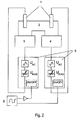
- FIG. 1 schematically shows a capacitive sensor arrangement according to the invention according to a first embodiment.
- a contacting surface of a pH sensor 3 and a penicillin-sensitive biosensor 4 for example, are in fluidic contact with the analyte 2 contained in the preferably aqueous sample liquid 2.
- Each sensor 3, 4 is assigned a reference electrode 1 (eg Ag / AgCl) which is incorporated in the Sample liquid 2 is immersed.
- additional electrodes eg, platinum wire
- the sensor backs are connected directly to two separate measurement circuits 5 by means of sensor back contact.
- Both measuring circuits 5 for capacitance measurement are constructed in the same way as already in the DE19708166 described. Each contains a controllable DC voltage source in series with an AC voltage source. The measuring principle is based on the fact that the capacitance of the sensor is determined by means of the AC voltage component U AC and the control of the DC voltage U BIAS determines the presence of the analyte (ie the additionally released ions). caused capacity change is corrected.
- the DC voltage potential applied to the sensor then corresponds to a measured value determined in the respective measuring circuit 5.
- the measuring electronics containing both measuring circuits 5 then, starting from the two measured values by means of a subtracting circuit 13, form the measuring signal M A , which directly indicates the concentration of the analyte.
- the difference between the two H + ion concentrations at the biosensor 4 and at the pH sensor 3 corresponds to the penicillin concentration in the sample liquid.
- FIG. 2 an optimized embodiment is shown, which additionally allows synchronization by means of synchronizer 6.
- the two measuring circuits 5 are alternately activated and deactivated by the synchronizer.
- FIG. 3 shows a further embodiment of the invention, which is a simplification of the embodiments according to FIG. 1 and 2 represents.
- a single reference electrode 1 dips into the analyte 2 and is in electrical connection to a measuring circuit 5, which is switched by means of switch 7 alternately (by control with a clock signal) either sensor back contacting the first sensor 3 or the second sensor 4.
- switch 7 alternately (by control with a clock signal) either sensor back contacting the first sensor 3 or the second sensor 4.
- an intermediate storage of the measured values obtained for the sensors takes place.
- the measuring principle and the evaluation are as in FIG. 4 shown expandable to any number of parallel connected sensors, the difference is determined in each case to the pH sensor.
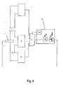
- FIG. 5 A fluidic realization of the embodiment of a sensor arrangement with two sensors is shown in FIG. 5 shown.
- a sample container with sample liquid 2 this is guided in a fluid channel 12 via a first valve 8 to a distributor nozzle 11, which sprays the first sensor 3 (pH sensor) and the second sensor 4 (penicillin sensor) on each sensor side with sample liquid.
- a reference electrode 1 dips into the fluid channel 12. The sensor backs and the reference electrode as described above have electrical connection with the measuring electronics (in Fig. 5 not shown).
- a container with buffer solution 10 supplies a second valve 9 with buffer solution which, in each case following one or more measurements, is conducted into the fluid channel 12 and reaches the sensors 3, 4 via the distributor nozzle 11. This The rinsing process downstream of the measurement ensures neutralization of the sensor surfaces and considerably extends the service life of the sensors.
- valves 8 and 9 are both closed in the idle mode, in the measuring mode valve 8 is open and valve 9 is closed, and in the cleaning mode, valve 8 is closed and valve 9 is opened.
Landscapes
- Chemical & Material Sciences (AREA)
- Engineering & Computer Science (AREA)
- Microelectronics & Electronic Packaging (AREA)
- Health & Medical Sciences (AREA)
- Life Sciences & Earth Sciences (AREA)
- Electrochemistry (AREA)
- Molecular Biology (AREA)
- Chemical Kinetics & Catalysis (AREA)
- Computer Hardware Design (AREA)
- Physics & Mathematics (AREA)
- Analytical Chemistry (AREA)
- Biochemistry (AREA)
- General Health & Medical Sciences (AREA)
- General Physics & Mathematics (AREA)
- Immunology (AREA)
- Pathology (AREA)
- Investigating Or Analyzing Materials By The Use Of Electric Means (AREA)
- Apparatus Associated With Microorganisms And Enzymes (AREA)
Abstract
Description
- Die Erfindung betrifft ein Verfahren zur Messung der Konzentration eines Analyten in einer Probeflüssigkeit. Ferner betrifft sie eine Vorrichtung zur Durchführung des Verfahrens.
- Sensoren auf Halbleiterbasis, die auf kapazitiven Messprinzipien beruhen, sind bekannt. Diese finden Anwendung auf dem Gebiet der Chemo- und Biosensoren. Unter Biosensoren versteht man Sensoren, die sich beispielsweise die Selektivität von Enzymen zu Nutze machen. Es sind bereits Biosensoren in Siliziumtechnologie bekannt, bei denen ein Enzym auf der Oberfläche des Sensors fixiert ist (
DE 44 36 001 C2 ). - Bei einer Gruppe von Sensoren findet am Sensor eine chemische Reaktion statt, die selektiv für ein Ion oder Molekül ist und bei der gleichzeitig eine pH-Wertänderung eintritt. Anwendungsbeispiele hierfür sind unter anderen die Bestimmung von Schwermetallen und Pestiziden im Abwasser, die Penicillinbestimmung und die DNA-Analyse.
- Diesen Sensoren ist gemeinsam, dass sie aufgebaut sind als pH-Sensoren, die mit einer zusätzlichen sensitiven Schicht für den zu bestimmenden Analyten ausgestattet sind, wobei die darunterliegende pH-Wert-sensitive Schicht weiterhin aktiv ist. Dieses Sensorprinzip hat zur Folge, dass mehrere Messungen hintereinander durchgeführt werden müssen, um die Konzentration eines Analyten angeben zu können, da vom Sensor sowohl der pH-Wert einer Probelösung erfasst wird als auch die zusätzliche pH-Wertänderung, die sich durch Reaktion des in der Probelösung vorhandenen Analyten mit der zweiten, sensitiven Schicht ergibt.
- Durch die in den Patentansprüchen angegebene Erfindung wird eine direkte Bestimmung der Analytkonzentration durch differentielle Messung ermöglicht.
- Die Erfindung wird im Folgenden beispielhaft für einen Penicillinsensor beschrieben, ist aber für alle Sensoren anwendbar, die auf dem Prinzip einer Sensorreaktion und gleichzeitiger pH-Wertänderung beruhen.
- An einem pH-Sensor, insbesondere mit Siliziumnitrid- oder Tantalpentoxidoberfläche oder einer anderen pH-Wert-sensitiven Oberfläche, wird ein Enzym fixiert, welches selektiv mit in einer zu messenden Probe vorhandenem Penicilin zu Penicillinsäure reagiert unter Freisetzung von H+ -Ionen. In der erfindungsgemäßen Messvorrichtung wird nun zur Bestimmung der Penicillinkonzentration eine Differenzmessung durchgeführt. Mit diesem Aufbau ist es möglich, direkt die Penicillinkonzentration zu bestimmen. So müssen nicht länger aufeinander folgende Messungen durchgeführt werden, wie es im Stand der Technik nötig ist.
- Zwei Sensoren stehen gleichzeitig in Kontakt mit der zu untersuchenden Probeflüssigkeit oder dem zu untersuchenden Probegas. Ein erster pH-Sensor, vorzugsweise als EIS-Struktur ausgebildet, ermittelt den pH-Wert der zu bestimmenden Probeflüssigkeit. Ein zweiter Sensor, der Biosensor, weist eine zum ersten Sensor identische Struktur auf, wobei zusätzlich auf eine pH-aktive Schicht die penicillinempfindliche, enzymbasierte Struktur folgt. An die penicillinempfindliche Struktur lagert sich in der Probeflüssigkeit vorhandenes Penicillin selektiv an, wobei das Penicillin zu Penicillinsäure reagiert und H+ -Ionen freigesetzt werden. Diese werden vom zweiten Sensor zusätzlich zu den H+ -Ionen detektiert, die dem ursprünglichen pH-Wert der Probeflüssigkeit entsprechen. Mittels elektronischer Auswerteeinheit wird durch Differenzbildung aus den Messsignalen beider Sensoren die H+ -lonen-Konzentration ermittelt, welche allein auf die enzymatische Reaktion zurück zu führen ist und die der Penicillinkonzentration entspricht.
- Besonders vorteilhaft ist die mögliche Miniaturisierung der beschriebenen Messvorrichtung sowohl hinsichtlich der fluidischen Komponenten als auch der Mess- und Auswerteelektronik zusammen in einer kompakten Baueinheit für industrielle Anwendungen.
- Zur Erhöhung der Lebensdauer der Sensoren ist eine abwechselnde Kontaktierung dieser mit der Probeflüssigkeit und einer Pufferlösung zur Neutralisierung mittels Sprühverfahren besonders günstig.
- Weitere Merkmale und Vorteile ergeben sich aus der folgenden Beschreibung unter Bezugnahme auf die beigefügten Zeichnungen. In den Zeichnungen zeigen:
-
Figur 1 eine erste Ausführungsform einer Sensoranordnung mit zwei Sensoren, -
Figur 2 eine zweite, synchronisierte Ausführungsform entsprechendFig. 1 , -
Figur 3 eine dritte Ausführungsform einer Sensoranordnung mit zwei Sensoren, -
Figur 4 eine Ausführungsform mit beliebiger Anzahl von Sensoren, -
Figur 5 die fluidische Realisierung der Ausführungsform einer Sensoranordnung mit zwei Sensoren. -
Figur 1 zeigt schematisch eine erfindungsgemäße, kapazitive Sensoranordnung gemäß einer ersten Ausführungsform. Jeweils eine Kontaktierungsfläche eines pH-Sensors 3 und eines beispielsweise penicillinempfindlichen Biosensors 4 stehen in fluidischem Kontakt mit dem in der vorzugsweise wässrigen Probeflüssigkeit 2 enthaltenen Analyten 2. Jedem Sensor 3, 4 ist eine Referenzelektrode 1 (z.B. Ag/AgCl) zugeordnet, die in die Probeflüssigkeit 2 eintaucht. Optional können zusätzliche Elektroden (z.B. Platindraht) eingesetzt werden, die zur Sicherstellung der Kontinuität der Messung vorteilhaft sein können. Die Sensorrückseiten sind mittels Sensorrückseitenkontaktierungen direkt an zwei separate Messschaltungen 5 angeschlossen. - Beide Messschaltungen 5 zur Kapazitätmessung sind in gleicher Weise aufgebaut, wie bereits in der
DE19708166 beschrieben. Jede enthält eine steuerbare Gleichspannungsquelle in Reihe mit einer Wechselspannungsquelle. Das Messprinzip beruht darauf, daß mittels des Wechselspannungsanteils UAC die Kapazität des Sensors bestimmt wird und über die Steuerung der Gleichspannung UBIAS die durch Anwesenheit des Analyten (d.h. die zusätzlich freigesetzten Ionen) verursachte Kapazitätsänderung ausgeregelt wird. Das an den Sensor angelegte Gleichspannungspotential entspricht dann einem in der jeweiligen Messschaltung 5 bestimmten Messwert. Die beide Messschaltungen 5 enthaltende Messelektronik bildet dann ausgehend von den beiden Messwerten mittels einer Subtrahierschaltung 13 das Messsignal MA, welches direkt die Konzentration des Analyten angibt. Bei dem gewählten Beispiel entspricht die Differenz aus den beiden H+ - Ionen-Konzentrationen am Biosensor 4 und am pH-Sensor 3 der Penicillinkonzentration in der Probeflüssigkeit. - In
Figur 2 ist eine optimierte Ausführungsform dargestellt, die zusätzlich eine Synchronisation mittels Synchronisator 6 ermöglicht. Die beiden Messschaltungen 5 werden durch den Synchronisator alternierend aktiviert und deaktiviert. -
Figur 3 zeigt eine weitere Ausführungsform der Erfindung, welche eine Vereinfachung der Ausführungsformen gemäßFigur 1 und2 darstellt. Eine einzige Referenzelektrode 1 taucht in den Analyten 2 ein und steht in elektrischer Verbindung zu einer Messschaltung 5, welche mittels Schalter 7 abwechselnd (durch Steuerung mit einem Taktsignal) entweder zur Sensorrückseitenkontaktierung des ersten Sensors 3 oder des zweiten Sensors 4 zugeschaltet wird. Für die Differenzberechnung erfolgt eine Zwischenspeicherung der für die Sensoren erhaltenen Messwerte. - Das Messprinzip und die Auswertung sind wie in
Figur 4 dargestellt auf eine beliebige Anzahl parallel geschalteter Sensoren erweiterbar, wobei die Differenz jeweils zum pH-Sensor bestimmt wird. - Eine fluidische Realisierung der Ausführungsform einer Sensoranordnung mit zwei Sensoren ist in
Figur 5 gezeigt. - Aus einem Probenbehälter mit Probeflüssigkeit 2 wird dieser in einem Fluidkanal 12 über ein erstes Ventil 8 zu einer Verteilerdüse 11 geführt, welche den ersten Sensor 3 (pH-Sensor) und den zweiten Sensor 4 (Penicillinsensor) jeweils auf einer Sensorseite mit Probeflüssigkeit besprüht. Eine Referenzelektrode 1 taucht in den Fluidkanal 12. Die Sensorrückseiten und die Referenzelektrode haben wie oben beschrieben elektrische Verbindung mit der Messelektronik (in
Fig. 5 nicht dargestellt). - Ein Behälter mit Pufferlösung 10 versorgt ein zweites Ventil 9 mit Pufferlösung, die jeweils im Anschluss an eine oder mehrere Messungen in den Fluidkanal 12 geleitet wird und über die Verteilerdüse 11 zu den Sensoren 3, 4 gelangt. Dieser der Messung nachgeschaltete Spülvorgang sorgt für eine Neutralisierung der Sensoroberflächen und verlängert die Lebensdauer der Sensoren erheblich.
- Die beiden Ventile 8 und 9 sind im Ruhemodus beide geschlossen, im Messmodus ist Ventil 8 geöffnet und Ventil 9 geschlossen, und im Reinigungsmodus ist Ventil 8 geschlossen und Ventil 9 geöffnet.
Claims (15)
- Verfahren zur Messung der Konzentration eines Analyten in einer Probeflüssigkeit oder in einem Probegas, bei dem in einer gemeinsamen Messzelle wenigstens zwei in Halbleitertechnologie ausgeführte kapazitive Feldeffekt-Sensoren angeordnet werden, die eine identische Grundstruktur aufweisen und von denen einer einen Meßsensor mit aktiver Transduktorschicht und ein anderer einen Referenzsensor ohne aktive Transduktorschicht bildet, wobei:- die Sensoren gleichzeitig mit der Probeflüssigkeit bzw. dem Probegas in Kontakt gebracht werden,- zwischen jedem Sensor und einer gleichzeitig von der Probeflüssigkeit bzw. dem Probegas kontaktierten Referenzelektrode eine Vorspannung angelegt wird, die sich aus einer elektrischen Gleichspannung und einer überlagerten Wechselspannung zusammensetzt,- über die Steuerung der an den Messsensor angelegten Vorspannung die durch den Analyt verursachte Kapazitätsänderung ausgeregelt wird,- ein Meßsignal erzeugt wird durch Berechnung der Differenz zwischen Spannungswerten, die für die Potentiale der an den Meßsensor bzw. an den Referenzsensor angelegten Gleichspannung repräsentativ sind,.
- Verfahren nach Anspruch 1, bei dem jeder Sensor eine ihm zugeordnete Referenzelektrode und eine zugeordnete elektronische Messschaltung aufweist, mit der die gesteuerte Vorspannung mit überlagerter Wechselspannung angelegt wird.
- Verfahren nach Anspruch 2, bei dem die Sensoren gleichzeitig betrieben werden.
- Verfahren nach Anspruch 2, bei dem die Sensoren alternierend mit nur einer elektronischen Messschaltung, die zwischen den Sensoren umgeschaltet wird, betrieben werden.
- Verfahren nach Anspruch 1, bei dem die Sensoren eine gemeinsame Referenzelektrode und eine gemeinsame elektronische Messschaltung haben und die gesteuerte Vorspannung mit überlagerter Wechselspannung alternierend zwischen der gemeinsamen Elektrode und einem der Sensoren angelegt wird.
- Verfahren nach Anspruch 5, bei dem in der Messzelle ein Referenzsensor und mehrere Sensoren mit verschiedenen Transduktorschichten angeordnet sind.
- Verfahren nach einem der vorstehenden Ansprüche, bei dem die Messzelle alternierend mit der den Analyten enthaltenden Probeflüssigkeit und einer Pufferlösung beaufschlagt wird.
- Verfahren nach einem der vorstehenden Ansprüche, bei dem die Sensoren pH-Werte oder Ionenkonzentrationen messen.
- Vorrichtung zur Messung der Konzentration eines Analyten in einer Probeflüssigkeit oder in einem Probegas, insbesondere zur Durchführung des Verfahrens nach einem der vorstehenden Ansprüche, mit einer gemeinsamen Messzelle, in der wenigstens zwei in Halbleitertechnologie ausgeführte kapazitive Feldeffekt-Sensoren angeordnet sind, die eine identische Grundstruktur aufweisen und von denen einer einen Meßsensor mit aktiver Transduktorschicht und ein anderer einen Referenzsensor ohne aktive Transduktorschicht bildet, und mit einer Messelektronik, die eine steuerbare Gleichspannungsquelle in Reihe mit einer Wechselspannungsquelle aufweist, um durch Steuerung der Gleichspannung Kapazitätsänderungen des Meßsensors, die durch den Analyt verursacht sind, auszuregeln und ein Meßsignal abzuleiten, indem die Differenz berechnet wird zwischen Spannungswerten, die für die Potentiale der an den Meßsensor bzw. an den Referenzsensor angelegten Gleichspannung repräsentativ sind.
- Vorrichtung nach Anspruch 9, bei der jedem Sensor eine eigene Referenzelektrode und eine eigene elektronische Messschaltung zugeordnet sind.
- Vorrichtung nach Anspruch 9, bei die Sensoren eine gemeinsame Referenzelektrode aufweisen, die durch einen der Sensoren gebildet sein kann.
- Vorrichtung nach Anspruch 11, bei die Sensoren eine gemeinsame elektronische Messschaltung aufweisen, die zwischen den Sensoren umschaltbar ist.
- Vorrichtung nach einem der Ansprüche 9 bis 12, bei dem die Feldeffekt-Sensoren pH-Wert-sensitiv oder ionensensitiv sind.
- Vorrichtung nach einem der Ansprüche 9 bis 13, bei dem die Transduktorschicht ein fixiertes Enzym aufweist.
- Vorrichtung nach einem der Ansprüche 9 bis 14, bei der die Messzelle durch alternierend gesteuerte Ventile mit einer Probeflüssigkeit und mit einer Pufferlösung beaufschlagbar ist.
Applications Claiming Priority (1)
| Application Number | Priority Date | Filing Date | Title |
|---|---|---|---|
| FR0952825A FR2945124B1 (fr) | 2009-04-29 | 2009-04-29 | Procede et dispositif de mesure de la concentration d'un analyte dans un liquide echantillon |
Publications (2)
| Publication Number | Publication Date |
|---|---|
| EP2246694A1 true EP2246694A1 (de) | 2010-11-03 |
| EP2246694B1 EP2246694B1 (de) | 2012-02-29 |
Family
ID=41479370
Family Applications (1)
| Application Number | Title | Priority Date | Filing Date |
|---|---|---|---|
| EP10004398A Active EP2246694B1 (de) | 2009-04-29 | 2010-04-26 | Verfahren und Vorrichtung zur Messung der Konzentration eines Analyten in einer Probeflüssigkeit |
Country Status (4)
| Country | Link |
|---|---|
| US (1) | US8432171B2 (de) |
| EP (1) | EP2246694B1 (de) |
| AT (1) | ATE547702T1 (de) |
| FR (1) | FR2945124B1 (de) |
Families Citing this family (6)
| Publication number | Priority date | Publication date | Assignee | Title |
|---|---|---|---|---|
| DE102006060921A1 (de) * | 2006-12-20 | 2008-06-26 | Endress + Hauser Gmbh + Co. Kg | Vorrichtung zur Bestimmung und/oder Überwachung einer Prozessgröße |
| DE102012210183B4 (de) | 2012-06-18 | 2017-03-23 | Siemens Healthcare Gmbh | Anordnung und Verfahren zur Analyse von Nukleinsäuresequenzen |
| US9053216B1 (en) | 2013-08-09 | 2015-06-09 | Datto, Inc. | CPU register assisted virtual machine screenshot capture timing apparatuses, methods and systems |
| US9861233B2 (en) | 2014-06-30 | 2018-01-09 | Pitco Frialator, Inc. | System and method for sensing oil quality |
| US9841394B2 (en) | 2015-11-16 | 2017-12-12 | Pitco Frialator, Inc. | System and method for sensing oil quality |
| US10436730B2 (en) | 2015-12-21 | 2019-10-08 | Pitco Frialator, Inc. | System and method for sensing oil quality |
Citations (4)
| Publication number | Priority date | Publication date | Assignee | Title |
|---|---|---|---|---|
| EP0213825A2 (de) * | 1985-08-22 | 1987-03-11 | Molecular Devices Corporation | Chemisch-modulierte Mehrfachkapazitanz |
| DE4436001C2 (de) | 1994-10-08 | 1996-07-25 | Forschungszentrum Juelich Gmbh | Biosensor mit auf einer Si¶3¶N¶4¶-Oberfläche fixiertem Enzym |
| DE19708166A1 (de) | 1997-02-28 | 1998-09-10 | Forschungszentrum Juelich Gmbh | Sensoranordnung zum Nachweis von Substanzen in einem Probenanalyten |
| WO2002052252A2 (de) * | 2000-12-23 | 2002-07-04 | Forschungszentrum Jülich GmbH | Elektronische messanordnung und verfahren zum nachweis von chemischen oder biochemischen komponenten, mit sensoren auf der basis von ionensensitiven feldeffekttransistoren |
Family Cites Families (38)
| Publication number | Priority date | Publication date | Assignee | Title |
|---|---|---|---|---|
| US3753092A (en) * | 1971-04-08 | 1973-08-14 | Johanna Plastics Inc | Liquid testing device for measuring changes in dielectric properties |
| US3903478A (en) * | 1974-07-30 | 1975-09-02 | Simmonds Precision Products | Fluid density measuring system |
| US4064455A (en) * | 1976-11-18 | 1977-12-20 | Hopkins Manufacturing Corporation | Fluid condition monitoring system |
| US4301401A (en) * | 1979-09-18 | 1981-11-17 | Phillips Petroleum Co. | Dielectric constant detector |
| US4692685A (en) * | 1984-03-14 | 1987-09-08 | Blaze Kevin L | Electrical measuring apparatus, and methods for determining the condition or identity of biological material |
| JPH01204675A (ja) * | 1988-02-10 | 1989-08-17 | Takeo Suzuki | 点滴容器内の液残量報知方法 |
| DE4034471C1 (de) * | 1990-10-30 | 1992-03-19 | Robert Bosch Gmbh, 7000 Stuttgart, De | |
| AU645151B2 (en) * | 1990-11-16 | 1994-01-06 | Siemens Aktiengesellschaft | Measuring instrument for determining the alcohol content of a mixture |
| JPH04319624A (ja) * | 1991-04-18 | 1992-11-10 | Olympus Optical Co Ltd | 液面検知装置 |
| JPH05133926A (ja) * | 1991-07-03 | 1993-05-28 | Nippondenso Co Ltd | 液体混合比率検出装置 |
| US5168240A (en) * | 1991-08-12 | 1992-12-01 | Simmonds Precision Products, Inc. | Capacitive fluid presence detector for gas pipe using an excited wire loop |
| US5313168A (en) * | 1991-11-06 | 1994-05-17 | Mitsubishi Denki Kabushiki Kaisha | Apparatus for detecting fuel dielectric constant |
| US5282381A (en) * | 1992-09-08 | 1994-02-01 | Hughes Aircraft Company | Supercritical fluid contamination monitor |
| US5321367A (en) * | 1992-09-21 | 1994-06-14 | The United States Of America As Represented By The Secretary Of The Army | Circuit for measuring capacitance at high DC bias voltage |
| DE69214455T2 (de) * | 1992-11-10 | 1997-04-30 | Agfa Gevaert Nv | Verwendung einer pH-empfindlichen Referenz-Elektrode für die elektrolytische Entsilberung |
| US5365783A (en) * | 1993-04-30 | 1994-11-22 | Packard Instrument Company, Inc. | Capacitive sensing system and technique |
| US6132893A (en) * | 1995-06-06 | 2000-10-17 | Forschungszentrum Julich Gmbh | pH-sensitive microsensor and a method of manufacturing a pH-sensitive microsensor |
| SE9703958D0 (sv) * | 1997-10-29 | 1997-10-29 | Pacesetter Ab | Method and device for determination of concentration |
| JP2000356619A (ja) * | 1999-06-14 | 2000-12-26 | Sumitomo Metal Ind Ltd | pHセンサおよびそれを使用したpH測定方法 |
| US6653842B2 (en) * | 2001-07-10 | 2003-11-25 | Digital Concepts Of Missouri | Galvanic probes as pH and oxidation reduction potential sensors, control devices employing such probes, and related methods |
| TW571101B (en) * | 2003-01-21 | 2004-01-11 | Ind Tech Res Inst | Fluid analysis apparatus |
| US8486255B2 (en) * | 2003-01-30 | 2013-07-16 | Emisense Technologies, Llc | System, apparatus, and method for measuring an ion concentration of a measured fluid |
| US7335336B1 (en) * | 2004-06-01 | 2008-02-26 | The United States Of America As Represented By The Secretary Of The Army | Sensor array using lateral field excited resonators |
| WO2006041224A1 (en) * | 2004-10-14 | 2006-04-20 | Kabushiki Kaisha Toshiba | Fet-based nucleic acid detecting sensor |
| TW200726973A (en) * | 2006-01-11 | 2007-07-16 | Univ Nat Yunlin Sci & Tech | PH meter and pH sensor thereof |
| EP1813348A1 (de) * | 2006-01-30 | 2007-08-01 | Bp Oil International Limited | Probenplatte für Fluidanalyse in einem Raffinerieprozess |
| TW200815750A (en) * | 2006-09-19 | 2008-04-01 | Univ Nat Yunlin Sci & Tech | System of measuring pH values of solutions and method for reducing time-drift effects of sensors thereof |
| US20120166095A1 (en) * | 2010-12-23 | 2012-06-28 | General Electric Company | Highly selective chemical and biological sensors |
| EP2100365B1 (de) * | 2006-12-08 | 2018-09-26 | Siemens Aktiengesellschaft | Überwachung der alterung der kondensatoren in einem umrichter mittels kapazitätsmessung |
| US8340928B2 (en) * | 2007-09-05 | 2012-12-25 | Yizhong Sun | Sensor and method for detecting oil deterioration and oil level |
| US8378694B2 (en) * | 2007-10-05 | 2013-02-19 | 3M Innovative Properties Company | Organic chemical sensor comprising plasma-deposited microporous layer, and method of making and using |
| US20090211924A1 (en) * | 2008-02-25 | 2009-08-27 | West Steven J | pH Electrode and Electrolyte |
| US20100301398A1 (en) * | 2009-05-29 | 2010-12-02 | Ion Torrent Systems Incorporated | Methods and apparatus for measuring analytes |
| US20110298481A1 (en) * | 2008-10-27 | 2011-12-08 | Smart Frequencies B.V. | Capacitance electrode and sensor-system capable of sensing contaminants and method therefor |
| DE102009016642A1 (de) * | 2009-04-07 | 2010-10-14 | Airbus Operations Gmbh | Verschlussvorrichtung, Gehäuseteil eines Schmiermittelbehälters, Diagnosesystem und Diagnoseverfahren zur Überwachung des Betriebszustands eines Schmiermittels in dem Gehäuseteil |
| US8860438B2 (en) * | 2009-05-11 | 2014-10-14 | Clemson University Research Foundation | Electrical double layer capacitive devices and methods of using same for sequencing polymers and detecting analytes |
| US20120261274A1 (en) * | 2009-05-29 | 2012-10-18 | Life Technologies Corporation | Methods and apparatus for measuring analytes |
| US8188754B2 (en) * | 2009-07-15 | 2012-05-29 | Maxim Integrated Products, Inc. | Method and apparatus for sensing capacitance value and converting it into digital format |
-
2009
- 2009-04-29 FR FR0952825A patent/FR2945124B1/fr not_active Expired - Fee Related
-
2010
- 2010-04-26 AT AT10004398T patent/ATE547702T1/de active
- 2010-04-26 EP EP10004398A patent/EP2246694B1/de active Active
- 2010-04-28 US US12/768,830 patent/US8432171B2/en not_active Expired - Fee Related
Patent Citations (4)
| Publication number | Priority date | Publication date | Assignee | Title |
|---|---|---|---|---|
| EP0213825A2 (de) * | 1985-08-22 | 1987-03-11 | Molecular Devices Corporation | Chemisch-modulierte Mehrfachkapazitanz |
| DE4436001C2 (de) | 1994-10-08 | 1996-07-25 | Forschungszentrum Juelich Gmbh | Biosensor mit auf einer Si¶3¶N¶4¶-Oberfläche fixiertem Enzym |
| DE19708166A1 (de) | 1997-02-28 | 1998-09-10 | Forschungszentrum Juelich Gmbh | Sensoranordnung zum Nachweis von Substanzen in einem Probenanalyten |
| WO2002052252A2 (de) * | 2000-12-23 | 2002-07-04 | Forschungszentrum Jülich GmbH | Elektronische messanordnung und verfahren zum nachweis von chemischen oder biochemischen komponenten, mit sensoren auf der basis von ionensensitiven feldeffekttransistoren |
Non-Patent Citations (7)
| Title |
|---|
| ARJANG HASSIBI ET AL: "A Programmable 0.18-CMOS Electrochemical Sensor Microarray for Biomolecular Detection", IEEE SENSORS JOURNAL, IEEE SERVICE CENTER, NEW YORK, NY, US LNKD- DOI:10.1109/JSEN.2006.883904, vol. 6, no. 6, 1 December 2006 (2006-12-01), pages 1380 - 1388, XP011150479, ISSN: 1530-437X * |
| POGHOSSIAN A ET AL: "(Bio-)chemical and physical microsensor arrays using an identical transducer principle", ELECTROCHIMICA ACTA, ELSEVIER SCIENCE PUBLISHERS, BARKING, GB LNKD- DOI:10.1016/S0013-4686(01)00562-X, vol. 47, no. 1-2, 1 September 2001 (2001-09-01), pages 243 - 249, XP004296923, ISSN: 0013-4686 * |
| POGHOSSIAN A ET AL: "An ISFET-based penicillin sensor with high sensitivity, low detection limit and long lifetime", SENSORS AND ACTUATORS B, ELSEVIER SEQUOIA S.A., LAUSANNE, CH LNKD- DOI:10.1016/S0925-4005(01)00609-8, vol. 76, no. 1-3, 1 June 2001 (2001-06-01), pages 519 - 526, XP004241167, ISSN: 0925-4005 * |
| POGHOSSIAN A ET AL: "Cross-sensitivity of a capacitive penicillin sensor combined with a diffusion barrier", SENSORS AND ACTUATORS B, ELSEVIER SEQUOIA S.A., LAUSANNE, CH, vol. 68, no. 1-3, 25 August 2000 (2000-08-25), pages 260 - 265, XP004216624, ISSN: 0925-4005 * |
| POGHOSSIAN, A; SCHÖNING, MJ: "Detecting Both Physical and (Bio-)Chemical Parameters by Means of ISFET Devices", ELECTROANALYSIS, vol. 16, no. 22, 28 September 2004 (2004-09-28), pages 1863 - 1872, XP002596394, DOI: 10.1002/elan.200403074 * |
| SCHONING M J ET AL: "A novel silicon-based sensor array with capacitive EIS structures", SENSORS AND ACTUATORS B, ELSEVIER SEQUOIA S.A., LAUSANNE, CH, vol. 47, no. 1-3, 30 April 1998 (1998-04-30), pages 225 - 230, XP004147342, ISSN: 0925-4005 * |
| THUST, M; SCHÖNING, MJ; VETTER, J; KORDOS, P; LÜTH, H: "A long-term stable penicillin-sensitive potentiometric biosensor with enzyme immobilized by heterobifunctional cross-linking", ANALYTICA CHIMICA ACTA, vol. 323, no. 1-3, 19 April 1996 (1996-04-19), pages 115 - 121, XP002563433 * |
Also Published As
| Publication number | Publication date |
|---|---|
| FR2945124B1 (fr) | 2011-07-08 |
| US20100308843A1 (en) | 2010-12-09 |
| US8432171B2 (en) | 2013-04-30 |
| EP2246694B1 (de) | 2012-02-29 |
| ATE547702T1 (de) | 2012-03-15 |
| FR2945124A1 (fr) | 2010-11-05 |
Similar Documents
| Publication | Publication Date | Title |
|---|---|---|
| EP2246694B1 (de) | Verfahren und Vorrichtung zur Messung der Konzentration eines Analyten in einer Probeflüssigkeit | |
| DE60207185T2 (de) | Biosensor-Vorrichtung und zugehöriges Verfahren zur Detektion von Art und Volumen einer Probe | |
| DE602004013438T2 (de) | Biosensorsystem | |
| DE102005003911A1 (de) | Verfahren zur Messung der Konzentration oder Konzentrationsänderung einer redoxaktiven Substanz und zugehörige Vorrichtung | |
| WO2004001405A1 (de) | Biosensor-array und verfahren zum betreiben eines biosensor-arrays | |
| EP1394534A2 (de) | vorrichtung zur ueberprüfung der positionierung und der blasenfreiheit einer medizinischen mikroprobe in einer durchflussmesszelle | |
| DE10015818A1 (de) | Biosensor und Verfahren zum Ermitteln makromolekularer Biopolymere mit einem Biosensor | |
| DE3116884A1 (de) | Verfahren und schaltung zur messung der ionenaktivitaet in fluessigkeiten | |
| WO2009147093A1 (de) | Verfahren zum detektieren von chemischen oder biologischen species sowie elektrodenanordnung hierfür | |
| DE202011101482U1 (de) | Vorrichtung zur Erfassung von Materialeigenschaften | |
| DE102014116777A1 (de) | Mikrofluidischer Sensor | |
| DE3226552C2 (de) | ||
| DE102012101254A1 (de) | Messanordnung und Verfahren zur Erfassung einer Analytkonzentration in einem Messmedium | |
| DE102019120446A1 (de) | Verfahren zur Korrektur von zwei Messwerten von jeweils verschiedener Analysenmessgeräte sowie Messstelle zum Ausführen des Verfahrens | |
| DE102004031371A1 (de) | Monolithisch integrierte Sensor-Anordnung, Sensor-Array und Verfahren zum Herstellen einer monolithisch integrierten Sensor-Anordnung | |
| DE102018124088A1 (de) | Elektronische Schaltung für einen elektrochemischen Sensor und Verfahren zur Sensorsignalmessung | |
| DE10259820A1 (de) | DNA-Chip mit Mikroarray aus Mikroelektrodensystemen | |
| DE102005037436A1 (de) | Verfahren und System zur Konzentrationsbestimmung eines Analyt-Enzym-Komplexes oder Analyt-Enzym-Konjugats, insbesondere zur elektrochemischen Detektion des Analyten, und zugehörige Messvorrichtung | |
| EP1328799B1 (de) | Elektronische schaltung, sensoranordnung und verfahren zum verarbeiten eines sensorsignals | |
| DE10015816A1 (de) | Biosensorchip | |
| DE102005003910A1 (de) | Elektrochemisches Transducer-Array und dessen Verwendung | |
| DE1773958A1 (de) | Verfahren zum Messen des Wassergehaltes von fluessigen Kohlenwasserstoffen | |
| EP1489408A1 (de) | Verfahren und Sensor zum Bestimmen eines chemischen Elements | |
| EP2264445B1 (de) | Coulometrischer Feuchtesensor und entsprechendes Verfahren | |
| DE19708166C2 (de) | Sensoranordnung zum Nachweis von Substanzen in einem Probenanalyten |
Legal Events
| Date | Code | Title | Description |
|---|---|---|---|
| PUAI | Public reference made under article 153(3) epc to a published international application that has entered the european phase |
Free format text: ORIGINAL CODE: 0009012 |
|
| AK | Designated contracting states |
Kind code of ref document: A1 Designated state(s): AT BE BG CH CY CZ DE DK EE ES FI FR GB GR HR HU IE IS IT LI LT LU LV MC MK MT NL NO PL PT RO SE SI SK SM TR |
|
| AX | Request for extension of the european patent |
Extension state: AL BA ME RS |
|
| 17P | Request for examination filed |
Effective date: 20101229 |
|
| 17Q | First examination report despatched |
Effective date: 20110214 |
|
| REG | Reference to a national code |
Ref country code: DE Ref legal event code: R079 Ref document number: 502010000451 Country of ref document: DE Free format text: PREVIOUS MAIN CLASS: G01N0027220000 Ipc: G01N0027414000 |
|
| GRAP | Despatch of communication of intention to grant a patent |
Free format text: ORIGINAL CODE: EPIDOSNIGR1 |
|
| RIC1 | Information provided on ipc code assigned before grant |
Ipc: G01N 27/414 20060101AFI20110909BHEP |
|
| GRAS | Grant fee paid |
Free format text: ORIGINAL CODE: EPIDOSNIGR3 |
|
| GRAA | (expected) grant |
Free format text: ORIGINAL CODE: 0009210 |
|
| AK | Designated contracting states |
Kind code of ref document: B1 Designated state(s): AT BE BG CH CY CZ DE DK EE ES FI FR GB GR HR HU IE IS IT LI LT LU LV MC MK MT NL NO PL PT RO SE SI SK SM TR |
|
| REG | Reference to a national code |
Ref country code: CH Ref legal event code: EP Ref country code: GB Ref legal event code: FG4D Free format text: NOT ENGLISH |
|
| REG | Reference to a national code |
Ref country code: AT Ref legal event code: REF Ref document number: 547702 Country of ref document: AT Kind code of ref document: T Effective date: 20120315 |
|
| REG | Reference to a national code |
Ref country code: IE Ref legal event code: FG4D Free format text: LANGUAGE OF EP DOCUMENT: GERMAN |
|
| REG | Reference to a national code |
Ref country code: DE Ref legal event code: R096 Ref document number: 502010000451 Country of ref document: DE Effective date: 20120426 |
|
| REG | Reference to a national code |
Ref country code: NL Ref legal event code: VDEP Effective date: 20120229 |
|
| LTIE | Lt: invalidation of european patent or patent extension |
Effective date: 20120229 |
|
| PG25 | Lapsed in a contracting state [announced via postgrant information from national office to epo] |
Ref country code: IS Free format text: LAPSE BECAUSE OF FAILURE TO SUBMIT A TRANSLATION OF THE DESCRIPTION OR TO PAY THE FEE WITHIN THE PRESCRIBED TIME-LIMIT Effective date: 20120629 Ref country code: NL Free format text: LAPSE BECAUSE OF FAILURE TO SUBMIT A TRANSLATION OF THE DESCRIPTION OR TO PAY THE FEE WITHIN THE PRESCRIBED TIME-LIMIT Effective date: 20120229 Ref country code: LT Free format text: LAPSE BECAUSE OF FAILURE TO SUBMIT A TRANSLATION OF THE DESCRIPTION OR TO PAY THE FEE WITHIN THE PRESCRIBED TIME-LIMIT Effective date: 20120229 Ref country code: HR Free format text: LAPSE BECAUSE OF FAILURE TO SUBMIT A TRANSLATION OF THE DESCRIPTION OR TO PAY THE FEE WITHIN THE PRESCRIBED TIME-LIMIT Effective date: 20120229 Ref country code: NO Free format text: LAPSE BECAUSE OF FAILURE TO SUBMIT A TRANSLATION OF THE DESCRIPTION OR TO PAY THE FEE WITHIN THE PRESCRIBED TIME-LIMIT Effective date: 20120529 |
|
| PG25 | Lapsed in a contracting state [announced via postgrant information from national office to epo] |
Ref country code: PT Free format text: LAPSE BECAUSE OF FAILURE TO SUBMIT A TRANSLATION OF THE DESCRIPTION OR TO PAY THE FEE WITHIN THE PRESCRIBED TIME-LIMIT Effective date: 20120629 Ref country code: LV Free format text: LAPSE BECAUSE OF FAILURE TO SUBMIT A TRANSLATION OF THE DESCRIPTION OR TO PAY THE FEE WITHIN THE PRESCRIBED TIME-LIMIT Effective date: 20120229 Ref country code: GR Free format text: LAPSE BECAUSE OF FAILURE TO SUBMIT A TRANSLATION OF THE DESCRIPTION OR TO PAY THE FEE WITHIN THE PRESCRIBED TIME-LIMIT Effective date: 20120530 Ref country code: FI Free format text: LAPSE BECAUSE OF FAILURE TO SUBMIT A TRANSLATION OF THE DESCRIPTION OR TO PAY THE FEE WITHIN THE PRESCRIBED TIME-LIMIT Effective date: 20120229 |
|
| REG | Reference to a national code |
Ref country code: IE Ref legal event code: FD4D |
|
| PG25 | Lapsed in a contracting state [announced via postgrant information from national office to epo] |
Ref country code: CY Free format text: LAPSE BECAUSE OF FAILURE TO SUBMIT A TRANSLATION OF THE DESCRIPTION OR TO PAY THE FEE WITHIN THE PRESCRIBED TIME-LIMIT Effective date: 20120229 |
|
| BERE | Be: lapsed |
Owner name: BURKERT WERKE G.M.B.H. Effective date: 20120430 Owner name: BURKERT & CIE. S.A.R.L. Effective date: 20120430 Owner name: FACHHOCHSCHULE AACHEN Effective date: 20120430 |
|
| PG25 | Lapsed in a contracting state [announced via postgrant information from national office to epo] |
Ref country code: SI Free format text: LAPSE BECAUSE OF FAILURE TO SUBMIT A TRANSLATION OF THE DESCRIPTION OR TO PAY THE FEE WITHIN THE PRESCRIBED TIME-LIMIT Effective date: 20120229 Ref country code: PL Free format text: LAPSE BECAUSE OF FAILURE TO SUBMIT A TRANSLATION OF THE DESCRIPTION OR TO PAY THE FEE WITHIN THE PRESCRIBED TIME-LIMIT Effective date: 20120229 Ref country code: IE Free format text: LAPSE BECAUSE OF FAILURE TO SUBMIT A TRANSLATION OF THE DESCRIPTION OR TO PAY THE FEE WITHIN THE PRESCRIBED TIME-LIMIT Effective date: 20120229 Ref country code: CZ Free format text: LAPSE BECAUSE OF FAILURE TO SUBMIT A TRANSLATION OF THE DESCRIPTION OR TO PAY THE FEE WITHIN THE PRESCRIBED TIME-LIMIT Effective date: 20120229 Ref country code: RO Free format text: LAPSE BECAUSE OF FAILURE TO SUBMIT A TRANSLATION OF THE DESCRIPTION OR TO PAY THE FEE WITHIN THE PRESCRIBED TIME-LIMIT Effective date: 20120229 Ref country code: EE Free format text: LAPSE BECAUSE OF FAILURE TO SUBMIT A TRANSLATION OF THE DESCRIPTION OR TO PAY THE FEE WITHIN THE PRESCRIBED TIME-LIMIT Effective date: 20120229 Ref country code: SE Free format text: LAPSE BECAUSE OF FAILURE TO SUBMIT A TRANSLATION OF THE DESCRIPTION OR TO PAY THE FEE WITHIN THE PRESCRIBED TIME-LIMIT Effective date: 20120229 Ref country code: DK Free format text: LAPSE BECAUSE OF FAILURE TO SUBMIT A TRANSLATION OF THE DESCRIPTION OR TO PAY THE FEE WITHIN THE PRESCRIBED TIME-LIMIT Effective date: 20120229 |
|
| PG25 | Lapsed in a contracting state [announced via postgrant information from national office to epo] |
Ref country code: MC Free format text: LAPSE BECAUSE OF NON-PAYMENT OF DUE FEES Effective date: 20120430 Ref country code: IT Free format text: LAPSE BECAUSE OF FAILURE TO SUBMIT A TRANSLATION OF THE DESCRIPTION OR TO PAY THE FEE WITHIN THE PRESCRIBED TIME-LIMIT Effective date: 20120229 Ref country code: SK Free format text: LAPSE BECAUSE OF FAILURE TO SUBMIT A TRANSLATION OF THE DESCRIPTION OR TO PAY THE FEE WITHIN THE PRESCRIBED TIME-LIMIT Effective date: 20120229 |
|
| PLBE | No opposition filed within time limit |
Free format text: ORIGINAL CODE: 0009261 |
|
| STAA | Information on the status of an ep patent application or granted ep patent |
Free format text: STATUS: NO OPPOSITION FILED WITHIN TIME LIMIT |
|
| PG25 | Lapsed in a contracting state [announced via postgrant information from national office to epo] |
Ref country code: BE Free format text: LAPSE BECAUSE OF NON-PAYMENT OF DUE FEES Effective date: 20120430 |
|
| 26N | No opposition filed |
Effective date: 20121130 |
|
| PG25 | Lapsed in a contracting state [announced via postgrant information from national office to epo] |
Ref country code: MK Free format text: LAPSE BECAUSE OF FAILURE TO SUBMIT A TRANSLATION OF THE DESCRIPTION OR TO PAY THE FEE WITHIN THE PRESCRIBED TIME-LIMIT Effective date: 20120229 |
|
| REG | Reference to a national code |
Ref country code: DE Ref legal event code: R097 Ref document number: 502010000451 Country of ref document: DE Effective date: 20121130 |
|
| PG25 | Lapsed in a contracting state [announced via postgrant information from national office to epo] |
Ref country code: ES Free format text: LAPSE BECAUSE OF FAILURE TO SUBMIT A TRANSLATION OF THE DESCRIPTION OR TO PAY THE FEE WITHIN THE PRESCRIBED TIME-LIMIT Effective date: 20120609 |
|
| PG25 | Lapsed in a contracting state [announced via postgrant information from national office to epo] |
Ref country code: BG Free format text: LAPSE BECAUSE OF FAILURE TO SUBMIT A TRANSLATION OF THE DESCRIPTION OR TO PAY THE FEE WITHIN THE PRESCRIBED TIME-LIMIT Effective date: 20120529 Ref country code: MT Free format text: LAPSE BECAUSE OF FAILURE TO SUBMIT A TRANSLATION OF THE DESCRIPTION OR TO PAY THE FEE WITHIN THE PRESCRIBED TIME-LIMIT Effective date: 20120229 |
|
| PG25 | Lapsed in a contracting state [announced via postgrant information from national office to epo] |
Ref country code: TR Free format text: LAPSE BECAUSE OF FAILURE TO SUBMIT A TRANSLATION OF THE DESCRIPTION OR TO PAY THE FEE WITHIN THE PRESCRIBED TIME-LIMIT Effective date: 20120229 |
|
| PG25 | Lapsed in a contracting state [announced via postgrant information from national office to epo] |
Ref country code: SM Free format text: LAPSE BECAUSE OF FAILURE TO SUBMIT A TRANSLATION OF THE DESCRIPTION OR TO PAY THE FEE WITHIN THE PRESCRIBED TIME-LIMIT Effective date: 20120229 Ref country code: LU Free format text: LAPSE BECAUSE OF NON-PAYMENT OF DUE FEES Effective date: 20120426 |
|
| PG25 | Lapsed in a contracting state [announced via postgrant information from national office to epo] |
Ref country code: HU Free format text: LAPSE BECAUSE OF FAILURE TO SUBMIT A TRANSLATION OF THE DESCRIPTION OR TO PAY THE FEE WITHIN THE PRESCRIBED TIME-LIMIT Effective date: 20100426 |
|
| REG | Reference to a national code |
Ref country code: CH Ref legal event code: PL |
|
| GBPC | Gb: european patent ceased through non-payment of renewal fee |
Effective date: 20140426 |
|
| PG25 | Lapsed in a contracting state [announced via postgrant information from national office to epo] |
Ref country code: LI Free format text: LAPSE BECAUSE OF NON-PAYMENT OF DUE FEES Effective date: 20140430 Ref country code: GB Free format text: LAPSE BECAUSE OF NON-PAYMENT OF DUE FEES Effective date: 20140426 Ref country code: CH Free format text: LAPSE BECAUSE OF NON-PAYMENT OF DUE FEES Effective date: 20140430 |
|
| REG | Reference to a national code |
Ref country code: FR Ref legal event code: PLFP Year of fee payment: 6 |
|
| REG | Reference to a national code |
Ref country code: FR Ref legal event code: PLFP Year of fee payment: 7 |
|
| REG | Reference to a national code |
Ref country code: AT Ref legal event code: MM01 Ref document number: 547702 Country of ref document: AT Kind code of ref document: T Effective date: 20150426 |
|
| PG25 | Lapsed in a contracting state [announced via postgrant information from national office to epo] |
Ref country code: AT Free format text: LAPSE BECAUSE OF NON-PAYMENT OF DUE FEES Effective date: 20150426 |
|
| REG | Reference to a national code |
Ref country code: FR Ref legal event code: PLFP Year of fee payment: 8 |
|
| REG | Reference to a national code |
Ref country code: FR Ref legal event code: PLFP Year of fee payment: 9 |
|
| PGFP | Annual fee paid to national office [announced via postgrant information from national office to epo] |
Ref country code: FR Payment date: 20230425 Year of fee payment: 14 Ref country code: DE Payment date: 20230427 Year of fee payment: 14 |