EP2246832A1 - Flight simulator vibration system - Google Patents
Flight simulator vibration system Download PDFInfo
- Publication number
- EP2246832A1 EP2246832A1 EP10400020A EP10400020A EP2246832A1 EP 2246832 A1 EP2246832 A1 EP 2246832A1 EP 10400020 A EP10400020 A EP 10400020A EP 10400020 A EP10400020 A EP 10400020A EP 2246832 A1 EP2246832 A1 EP 2246832A1
- Authority
- EP
- European Patent Office
- Prior art keywords
- flight simulator
- vibration system
- electro
- flight
- motors
- Prior art date
- Legal status (The legal status is an assumption and is not a legal conclusion. Google has not performed a legal analysis and makes no representation as to the accuracy of the status listed.)
- Granted
Links
- RZVHIXYEVGDQDX-UHFFFAOYSA-N 9,10-anthraquinone Chemical compound C1=CC=C2C(=O)C3=CC=CC=C3C(=O)C2=C1 RZVHIXYEVGDQDX-UHFFFAOYSA-N 0.000 claims abstract description 16
- 230000000153 supplemental effect Effects 0.000 claims description 11
- 238000004088 simulation Methods 0.000 description 14
- 230000010355 oscillation Effects 0.000 description 3
- 230000000694 effects Effects 0.000 description 2
- 238000009434 installation Methods 0.000 description 2
- 238000012546 transfer Methods 0.000 description 2
- 240000006829 Ficus sundaica Species 0.000 description 1
- XAGFODPZIPBFFR-UHFFFAOYSA-N aluminium Chemical compound [Al] XAGFODPZIPBFFR-UHFFFAOYSA-N 0.000 description 1
- 229910052782 aluminium Inorganic materials 0.000 description 1
- 239000004411 aluminium Substances 0.000 description 1
- 230000002950 deficient Effects 0.000 description 1
- 238000013461 design Methods 0.000 description 1
- 238000001914 filtration Methods 0.000 description 1
- 230000010354 integration Effects 0.000 description 1
- 206010025482 malaise Diseases 0.000 description 1
- 238000013178 mathematical model Methods 0.000 description 1
- 238000005259 measurement Methods 0.000 description 1
- 238000000034 method Methods 0.000 description 1
- 238000002360 preparation method Methods 0.000 description 1
- 238000012545 processing Methods 0.000 description 1
- 238000011084 recovery Methods 0.000 description 1
- 238000000638 solvent extraction Methods 0.000 description 1
- 239000013589 supplement Substances 0.000 description 1
- 238000012360 testing method Methods 0.000 description 1
Images


Classifications
-
- G—PHYSICS
- G09—EDUCATION; CRYPTOGRAPHY; DISPLAY; ADVERTISING; SEALS
- G09B—EDUCATIONAL OR DEMONSTRATION APPLIANCES; APPLIANCES FOR TEACHING, OR COMMUNICATING WITH, THE BLIND, DEAF OR MUTE; MODELS; PLANETARIA; GLOBES; MAPS; DIAGRAMS
- G09B9/00—Simulators for teaching or training purposes
- G09B9/02—Simulators for teaching or training purposes for teaching control of vehicles or other craft
- G09B9/08—Simulators for teaching or training purposes for teaching control of vehicles or other craft for teaching control of aircraft, e.g. Link trainer
- G09B9/46—Simulators for teaching or training purposes for teaching control of vehicles or other craft for teaching control of aircraft, e.g. Link trainer the aircraft being a helicopter
-
- G—PHYSICS
- G09—EDUCATION; CRYPTOGRAPHY; DISPLAY; ADVERTISING; SEALS
- G09B—EDUCATIONAL OR DEMONSTRATION APPLIANCES; APPLIANCES FOR TEACHING, OR COMMUNICATING WITH, THE BLIND, DEAF OR MUTE; MODELS; PLANETARIA; GLOBES; MAPS; DIAGRAMS
- G09B9/00—Simulators for teaching or training purposes
- G09B9/02—Simulators for teaching or training purposes for teaching control of vehicles or other craft
- G09B9/08—Simulators for teaching or training purposes for teaching control of vehicles or other craft for teaching control of aircraft, e.g. Link trainer
- G09B9/16—Ambient or aircraft conditions simulated or indicated by instrument or alarm
- G09B9/165—Condition of cabin, cockpit or pilot's accessories
Definitions
- the invention relates to a flight simulator vibration system, particularly to a crew seat, a flight control stick and a panel vibration system of a flight simulator with the features of the preamble of claim 1.
- a highfrequency, low-amplitude motion with a three degree of freedom (3DOF) seat shaker / motion system allows simulator systems integrators to provide motion and vibration cues to an operator without the expense of a full cab motion system providing pitch, roll and heave cues to the operator's seat based on the simulated vehicle's motion.
- Vehicle X and Y cues are also blended into the motion to provide realistic driving cues. Vibrations of 10 Hz until 40 Hz, with a preferred value of 25 to 26 Hz, depending on the vibrations simulated, can be provided to each of the three degrees of freedom.
- the seat motion system control electronics are packaged as a self-contained simulation node that performs the required cueing algorithms locally at a high iteration rate and can communicate with other simulation components over serial or Ethernet connections.
- the node receives vehicle state information from the vehicle dynamics model as well as vibration and discrete bump commands.
- motion simulators including 6-post motion platforms with the platform being supported by 6 active hydraulic actuators.
- the 6-post is essentially a hydraulic position servo driven by commanded leg or actuator lengths computed by a motion system mathematical model.
- US 2009154737 discloses an apparatus, system and method for an entertainment chair to provide a high fidelity audio system incorporated in an entertainment chair.
- the entertainment chair is relatively independent from an acoustical environment in which it is placed and enables repeatable high fidelity sound with a wide variety of recording types and qualities.
- a subwoofer is placed in the backrest and a shaker is placed in the seat bottom.
- the subwoofer and shaker are separately tuneable through a control panel ergonomically placed at a forward end of an arm rest.
- the control panel includes a universal iPod dock.
- Other inputs may also be connected to the entertainment chair. This system is dedicated to personal entertainment and is not suitable for any flight simulation.
- a flight simulator vibration system is provided with at least one crew seat, at least one flight control stick and at least one panel vibration system comprising each predefined momentum weights and electric motors driving said respective momentum weights and at least one speed governor controlling preferably individually said electric motors.
- a flight simulator crew seat comprises at least one supplemental plate integrated into the seat with predefined momentum weights and three electric motors for each plate driving said respective momentum weights.
- An electronic control circuit is provided particularly conceived as speed governor controlling said three electric motors in order to provide different frequencies of oscillation and orientation to the momentum weights in the direction of all three coordinate axis.
- the seat of the invention is built up from an original crew seat and thus looks the same and feels the same as an original seat and provides for a genuine flight feeling and reflection of the real oscillations of an aircraft.
- the flight simulator crew seat of the invention may be used in a full flight simulator (FFS) after certification and approval from the authorities in charge.
- FFS full flight simulator
- the inventive flight simulator crew seat can be built up from all original crew seats and without extra time consumption. Considerable savings in costs may be achieved with the inventive system as deficient systems through oscillation damages can be avoided.
- the inventive system is less bulky and leads to less weight than with a flight simulator crew seat according to the state of the art.
- the inventive system can be extended to customized solutions.
- the control is driven by low voltage current in the range of up to 14 V thus avoiding any risks from the electric supply of the electro-motors to any users.
- the electronic control circuit is independent without any need any to intercept into any existing systems for installation of the inventive flight simulator vibration system.
- said control may be tuned according to the frequencies of sounds created in a simulation independent of any existing computer system with the frequencies of sounds created in the simulation corresponding preferably to the frequencies of a turbine, rotor or tail rotor of a helicopter.
- the electronic control circuit is invisibly arranged outside the seat for improved modularity and better acceptance by the clients.
- the inventive seat may be fully adjustable with no restrictions from the inventive system.
- the at least one supplemental plate is mounted to a backrest of the crew seat for transfer of its simulated vibrations directly to the back of the user in the seat.
- At least one further supplemental plate is mounted to a sitting support of the crew seat for transfer of its simulated vibrations directly to the legs and body of the user in the seat.
- each supplemental plate is provided with three electric motors each driving respectively one momentum weight for common control features of the simulated vibrations in separate plates.
- flexible stripes are provided being arranged across casings of the electro-motors and screwed at their respective ends to the plate for economic and versatile installation of the electro- motors allowing easy rotation of the electro-motors.
- the technical effect is that by turning the motor casing the force direction is adjusted.
- At least one control processor is provided and a DC pulse transformer as an interface to the electronic control circuit for filtering and preparation of the data for the control of the electro-motors.
- microphones are provided, data from the microphones are filtered by the audio-frequency splitter and converted inside the control processor in order to allow simulation of vibrations corresponding to operational sounds, such as the sound from a rotor of an operating helicopter.
- At least one external device is provided for transmittal of analog input data reflecting speed and/or flying position data (attitude) and/or digital input reflecting critical levels of flying position like a maximum bank angle.
- the analog and/or digital input goes directly to the electronic control circuit to allow integration of complex influences to the simulation of vibrations.
- a flight control stick vibration system is provided with an electro-motor with a momentum weight mounted eccentrically inside a security casing integral with the electro-motor allowing essentially modulated simulation of vibration in the flight control stick with the features of the vibration system of the at least one crew seat.
- a panel vibration system characterized in that at least one glare-shield is provided, said panel being provided with two electro-motors with respective momentum weights allowing reproduction of vibrations in said glare-shield with essentially the features of the vibration system of the at least one crew seat and/or the flight control stick.
- the momentum weights are adjustable and/or can be replaced for simple and versatile adaption of the flight simulator vibration system to a wide range of different samples.
- the electro-motors can be rotated for simple and effective tuning of the simulated vibrations.
- the technical effect is that it allows the force direction to change.
- the respective momentum weights and their respective orientations are calibrated for a start sample and consequent proceedings.
- three electronic control circuits are provided for shared processing with a back-up option and with at least one of said electronic control circuits being conceived as speed governor.
- a flight simulator vibration system for an aircraft and particularly for a helicopter has as a basis a fully adjustable standard crew seat 1 of a helicopter (not shown) with all the features of a genuine crew seat particularly a cover 2 that can be opened and closed via a zip along a vertical direction of the backrest 3 of this crew seat 1.
- An essentially rectangular plate 4 is mounted as a supplemental essentially parallel to the backrest 3 of this crew seat 1.
- the plate 4 is made of aluminium with a 3-4 mm thickness and is fixed to a frame of the backrest 3 of crew seat 1 by way of screws and clamps 5.
- Three independent, flexible stripes 6 are arranged across casings of electro-motors 7, 8, 9 and are screwed at their respective ends to the plate 4 to hold down the three casings of the electro-motors 7, 8, 9 against the plate 4.
- the three electro-motors 7, 8, 9 are mounted to the plate 4 from the side opposed to the pilot's back.
- Two electro-motors 8, 9 are mounted to an upper part of the plate 4 and one electro-motor 7 is mounted to a lower part of the plate 4 with the electro-motors 7, 8, 9 having about the same distances between each other.
- Each of the flexible stripes 6 can be loosened individually by unscrewing at least one of their respective ends allowing the electro-motors 7, 8, 9 to be rotated individually in the plane of the plate 4 and relative to each other. This allows to adjust the force direction
- Flight operation data may be processed for genuine flight simulations. Audio data with real flight manoeuvre sound track may be recorded by microphones 10 transmitting frequencies to a control processor 11 for the electro-motors 7, 8, 9. The frequencies from the microphones input 10 are filtered and processed in the control processor 11 via a DC pulse transformer (not shown) to control parameters, i. e. by partitioning the supply voltage for the respective electro-motors 7, 8, 9.
- the control processor 11 is linked via a sub D interface to an electronic control circuit 12 and from there via shielded cables to the electro-motors 7, 8, 9.
- Analog input with data of speed and/or flying position and digital input with data of speed limits and/or critical levels of flying position like a maximum bank angle may be fed directly to the electronic control circuit 12 from an external device 14.
- the electronic control circuit 12 is conceived as speed governor for the electro-motors 7, 8, 9.
- the electric power supply for the electro-motors 7, 8, 9 is based on 12-14 Volt transformed from the generally available 220 V (in the USA 110 V).
- An essentially rectangular lower plate 4a is integrated as a supplemental seat shaker into a sitting support of a flight simulator crew seat 1.
- the lower plate 4a as well as electro-motors and the assembly of the lower plate 4a with the electro-motors correspond principally to the essentially rectangular plate 4 mounted as a supplement to the backrest 3 of this crew seat 1 of the flight simulator vibration system.
- the control and supply of the electro-motors of the lower plate 4a corresponds to the control and supply of the electro-motors 7, 8, 9 of the plate 4 at the backrest 3 of the crew seat 1.
- Rubber dampers 17 are provided at each of the corners of the lower plate 4a for attenuating the impact of the vibrations from the lower plate 4a to the crew seat 1 of the flight simulator vibration system.
- the electro-motors 7, 8, 9 can be tuned individually up to 3000 RPM depending from the input from the electronic control circuits 12.
- Each of the electro-motors 7, 8, 9 comprises a power shaft 15 to which a momentum weight 13 is mounted eccentrically inside a security casing 17 integral with the electro-motors 7, 8, 9.
- the momentum weights 13 are rotating masses between 0,4 g to 400 g individually orientated to provide for different frequencies and orientations of the vibrations. Eccentricity of the respective momentum weights 13 may be adjustable by extra momentum weights 16 (s. Fig. 4 ) that can be displaced radially with regard to the axis of the power shaft 15.
- the security casing 17 is provided with an access to allow replacement and/or adjustment of the momentum weights 13, 16.
- the orientation of the momentum weights 13, 16 can be tuned by rotating the electro-motors 7, 8, 9 individually or relative to each other under the loosened stripes 6 parallel to the plane of the plate 4. At least one of a pair of adjacent electro-motors 7, 8, 9 is rotating anti-clockwise while the other one is rotating clockwise.
- the respective momentum weights 13, 16 and their respective orientations are first calibrated to correspond best to measurements of an operating aircraft to be simulated (not shown). For this end the amplitudes and frequencies of vibrations during operation of an aircraft are measured and registered and the registered data are transferred to the crew seat 1 of the flight simulator vibration system.
- the speed controllers 12 may be adapted to the registered measures to tune the rotational speed of the electro-motors 7, 8, 9 till the amplitudes and frequencies of the vibrations at the crew seat 1 of the flight simulator vibration system correspond to the registered measures.
- a profile from a plurality of registered measures can be created and stored in a memory to provide simulation of ongoing flight operations to the electro-motors.
- a helicopter main rotor at approximately 390 RPM and with 4 blades provides vibrations at frequencies of approximately 25/26 Hz. Thus for such a case vibrations resulting from the frequencies at 25/26 Hz have to be simulated in the crew seat 1.
- FIG. 5 Corresponding features are numbered with the same references as in Fig. 1 to 4 .
- a flight control stick 20 of a flight simulator vibration system is provided with an electro-motor 21 with a momentum weight mounted eccentrically inside an integral security casing alike any of the electro-motors 7, 8, 9.
- a clamp 22 around the electro-motor 21 with the security casing is screwed to the flight control stick 20 next to the joints 23 linking the flight control stick 20 to the flight simulator vibration system.
- the electro-motor 21 is connected to the electric power supply via a power cable and to the electronic control circuit 12 via shielded cables 24.
- FIG. 6 Corresponding features are numbered with the same references as in Fig. 1 to 5 .
- a panel 30 of a flight simulator vibration system is equipped with a glare-shield 31, such glare-shield 31 being supposed to avoid blinding of the instruments 32 by sunshine and thus obstructing the pilot's view in flight operation.
- the panel 30 is provided with two electro-motors 33, 34 with respective momentum weights allowing reproduction of vibrations of 4 Rev in the glare-shield corresponding to vibrations during genuine flight operation at a speed of ⁇ 17 and 24 kts.
- the electro-motors 33, 34 of the panel 30 are alike any of the electro-motors 7, 8, 9 and are controlled by the electronic control circuits 12 for the crew seat 1 of the flight simulator vibration system.
Abstract
Description
- The invention relates to a flight simulator vibration system, particularly to a crew seat, a flight control stick and a panel vibration system of a flight simulator with the features of the preamble of claim 1.
- The design of a low-cost simulation system to replicate helicopter/shipboard launch and recovery envelopes reduces the reliance on expensive at-sea developmental flight tests. A highfrequency, low-amplitude motion with a three degree of freedom (3DOF) seat shaker / motion system allows simulator systems integrators to provide motion and vibration cues to an operator without the expense of a full cab motion system providing pitch, roll and heave cues to the operator's seat based on the simulated vehicle's motion. Vehicle X and Y cues are also blended into the motion to provide realistic driving cues. Vibrations of 10 Hz until 40 Hz, with a preferred value of 25 to 26 Hz, depending on the vibrations simulated, can be provided to each of the three degrees of freedom. The seat motion system control electronics are packaged as a self-contained simulation node that performs the required cueing algorithms locally at a high iteration rate and can communicate with other simulation components over serial or Ethernet connections. The node receives vehicle state information from the vehicle dynamics model as well as vibration and discrete bump commands.
- For flight simulation it is known to use motion simulators including 6-post motion platforms with the platform being supported by 6 active hydraulic actuators. The 6-post is essentially a hydraulic position servo driven by commanded leg or actuator lengths computed by a motion system mathematical model.
- Seat shakers of the state of the art are different from the original seat and very expensive. Their control is effected via complicated software and necessitates interference with existing system components. Some of the vibrations created by the seat shakers of the state of the art are likely to deteriorate the operation of adjacent systems.
-
US 2009154737 (A1 ) discloses an apparatus, system and method for an entertainment chair to provide a high fidelity audio system incorporated in an entertainment chair. The entertainment chair is relatively independent from an acoustical environment in which it is placed and enables repeatable high fidelity sound with a wide variety of recording types and qualities. A subwoofer is placed in the backrest and a shaker is placed in the seat bottom. The subwoofer and shaker are separately tuneable through a control panel ergonomically placed at a forward end of an arm rest. The control panel includes a universal iPod dock. Other inputs may also be connected to the entertainment chair. This system is dedicated to personal entertainment and is not suitable for any flight simulation. - It is an object of the present invention to provide a flight simulator vibration system, particularly a crew seat, a flight control stick and a panel vibration system of a flight simulator without the disadvantages of the state of the art and improving the feeling of a pilot or a crew in order to present an utmost realistic flight simulation.
- The solution is provided with a flight simulator vibration system, particularly a crew seat, a flight control stick and a panel vibration system of a flight simulator with the features of claim 1. Preferred embodiments of the invention are provided in the sub claims.
- According to the invention a flight simulator vibration system is provided with at least one crew seat, at least one flight control stick and at least one panel vibration system comprising each predefined momentum weights and electric motors driving said respective momentum weights and at least one speed governor controlling preferably individually said electric motors. The invention provides the advantages of a complete and modular flight simulator vibration system.
- According to a preferred embodiment of the invention a flight simulator crew seat comprises at least one supplemental plate integrated into the seat with predefined momentum weights and three electric motors for each plate driving said respective momentum weights. An electronic control circuit is provided particularly conceived as speed governor controlling said three electric motors in order to provide different frequencies of oscillation and orientation to the momentum weights in the direction of all three coordinate axis. It is one advantage of the present invention to provide a flight simulator crew seat vibration system improving the feeling of a pilot or a crew for an utmost realistic flight simulation. The inventive flight simulator crew seat supplies the means to avoid the so called simulator sickness. The seat of the invention is built up from an original crew seat and thus looks the same and feels the same as an original seat and provides for a genuine flight feeling and reflection of the real oscillations of an aircraft. The flight simulator crew seat of the invention may be used in a full flight simulator (FFS) after certification and approval from the authorities in charge. The inventive flight simulator crew seat can be built up from all original crew seats and without extra time consumption. Considerable savings in costs may be achieved with the inventive system as deficient systems through oscillation damages can be avoided. The inventive system is less bulky and leads to less weight than with a flight simulator crew seat according to the state of the art. The inventive system can be extended to customized solutions. According to the invention the control is driven by low voltage current in the range of up to 14 V thus avoiding any risks from the electric supply of the electro-motors to any users. According to the invention the electronic control circuit is independent without any need any to intercept into any existing systems for installation of the inventive flight simulator vibration system. Advantageously said control may be tuned according to the frequencies of sounds created in a simulation independent of any existing computer system with the frequencies of sounds created in the simulation corresponding preferably to the frequencies of a turbine, rotor or tail rotor of a helicopter. According to a further aspect of the invention the electronic control circuit is invisibly arranged outside the seat for improved modularity and better acceptance by the clients. The inventive seat may be fully adjustable with no restrictions from the inventive system.
- According to a further preferred embodiment of the invention the at least one supplemental plate is mounted to a backrest of the crew seat for transfer of its simulated vibrations directly to the back of the user in the seat.
- According to a further preferred embodiment of the invention at least one further supplemental plate is mounted to a sitting support of the crew seat for transfer of its simulated vibrations directly to the legs and body of the user in the seat.
- According to a further preferred embodiment of the invention each supplemental plate is provided with three electric motors each driving respectively one momentum weight for common control features of the simulated vibrations in separate plates.
- According to a further preferred embodiment of the invention flexible stripes are provided being arranged across casings of the electro-motors and screwed at their respective ends to the plate for economic and versatile installation of the electro- motors allowing easy rotation of the electro-motors. The technical effect is that by turning the motor casing the force direction is adjusted.
- According to a further preferred embodiment of the invention at least one control processor is provided and a DC pulse transformer as an interface to the electronic control circuit for filtering and preparation of the data for the control of the electro-motors.
- According to a further preferred embodiment of the invention microphones are provided, data from the microphones are filtered by the audio-frequency splitter and converted inside the control processor in order to allow simulation of vibrations corresponding to operational sounds, such as the sound from a rotor of an operating helicopter.
- According to a further preferred embodiment of the invention at least one external device is provided for transmittal of analog input data reflecting speed and/or flying position data (attitude) and/or digital input reflecting critical levels of flying position like a maximum bank angle. The analog and/or digital input goes directly to the electronic control circuit to allow integration of complex influences to the simulation of vibrations.
- According to another preferred embodiment of the invention a flight control stick vibration system is provided with an electro-motor with a momentum weight mounted eccentrically inside a security casing integral with the electro-motor allowing essentially modulated simulation of vibration in the flight control stick with the features of the vibration system of the at least one crew seat.
- According to another preferred embodiment of the invention A panel vibration system according to claim 1, characterized in that at least one glare-shield is provided, said panel being provided with two electro-motors with respective momentum weights allowing reproduction of vibrations in said glare-shield with essentially the features of the vibration system of the at least one crew seat and/or the flight control stick.
- According to a preferred embodiment of the invention the momentum weights are adjustable and/or can be replaced for simple and versatile adaption of the flight simulator vibration system to a wide range of different samples.
- According to a preferred embodiment of the invention the electro-motors can be rotated for simple and effective tuning of the simulated vibrations. The technical effect is that it allows the force direction to change.
- According to a preferred embodiment of the invention the respective momentum weights and their respective orientations are calibrated for a start sample and consequent proceedings.
- According to a preferred embodiment of the invention three electronic control circuits are provided for shared processing with a back-up option and with at least one of said electronic control circuits being conceived as speed governor.
- A preferred embodiment of the invention will be described by way of the attached drawings.
-
Fig. 1 shows a view from behind onto a crew seat of a flight simulator vibration system according to the invention, -
Fig. 2 shows a schematic view of a part of a seat of a flight simulator vibration system according to the invention, -
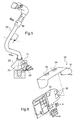
Fig. 3 shows a schematic view of a lower plate of a seat of a flight simulator vibration system according to the invention, -
Fig. 4 shows a schematic view of an electro motor of a flight simulator vibration system according to the invention, -
Fig. 5 shows a schematic view of a flight control stick of a flight simulator vibration system according to the invention, and -
Fig. 6 shows a schematic view of a panel vibration system of a flight simulator vibration system according to the invention. -
Fig. 1 : A flight simulator vibration system for an aircraft and particularly for a helicopter, has as a basis a fully adjustable standard crew seat 1 of a helicopter (not shown) with all the features of a genuine crew seat particularly acover 2 that can be opened and closed via a zip along a vertical direction of thebackrest 3 of this crew seat 1. - An essentially
rectangular plate 4 is mounted as a supplemental essentially parallel to thebackrest 3 of this crew seat 1. Theplate 4 is made of aluminium with a 3-4 mm thickness and is fixed to a frame of thebackrest 3 of crew seat 1 by way of screws andclamps 5. - Three independent,
flexible stripes 6 are arranged across casings of electro-motors plate 4 to hold down the three casings of the electro-motors plate 4. The three electro-motors plate 4 from the side opposed to the pilot's back. Two electro-motors plate 4 and one electro-motor 7 is mounted to a lower part of theplate 4 with the electro-motors flexible stripes 6 can be loosened individually by unscrewing at least one of their respective ends allowing the electro-motors plate 4 and relative to each other. This allows to adjust the force direction -
Fig. 2, 3, 4 : Corresponding features are numbered with the same references as inFig. 1 . Flight operation data may be processed for genuine flight simulations. Audio data with real flight manoeuvre sound track may be recorded bymicrophones 10 transmitting frequencies to acontrol processor 11 for the electro-motors microphones input 10 are filtered and processed in thecontrol processor 11 via a DC pulse transformer (not shown) to control parameters, i. e. by partitioning the supply voltage for the respective electro-motors control processor 11 is linked via a sub D interface to anelectronic control circuit 12 and from there via shielded cables to the electro-motors electronic control circuit 12 from anexternal device 14. Theelectronic control circuit 12 is conceived as speed governor for the electro-motors motors - An essentially rectangular
lower plate 4a is integrated as a supplemental seat shaker into a sitting support of a flight simulator crew seat 1. Thelower plate 4a as well as electro-motors and the assembly of thelower plate 4a with the electro-motors correspond principally to the essentiallyrectangular plate 4 mounted as a supplement to thebackrest 3 of this crew seat 1 of the flight simulator vibration system. The control and supply of the electro-motors of thelower plate 4a corresponds to the control and supply of the electro-motors plate 4 at thebackrest 3 of the crew seat 1.Rubber dampers 17 are provided at each of the corners of thelower plate 4a for attenuating the impact of the vibrations from thelower plate 4a to the crew seat 1 of the flight simulator vibration system. - The electro-
motors electronic control circuits 12. Each of the electro-motors power shaft 15 to which amomentum weight 13 is mounted eccentrically inside asecurity casing 17 integral with the electro-motors momentum weights 13 are rotating masses between 0,4 g to 400 g individually orientated to provide for different frequencies and orientations of the vibrations. Eccentricity of therespective momentum weights 13 may be adjustable by extra momentum weights 16 (s.Fig. 4 ) that can be displaced radially with regard to the axis of thepower shaft 15. Thesecurity casing 17 is provided with an access to allow replacement and/or adjustment of themomentum weights momentum weights motors stripes 6 parallel to the plane of theplate 4. At least one of a pair of adjacent electro-motors - The
respective momentum weights speed controllers 12 may be adapted to the registered measures to tune the rotational speed of the electro-motors -
Fig. 5 : Corresponding features are numbered with the same references as inFig. 1 to 4 . Aflight control stick 20 of a flight simulator vibration system is provided with an electro-motor 21 with a momentum weight mounted eccentrically inside an integral security casing alike any of the electro-motors clamp 22 around the electro-motor 21 with the security casing is screwed to theflight control stick 20 next to thejoints 23 linking theflight control stick 20 to the flight simulator vibration system. - The electro-
motor 21 is connected to the electric power supply via a power cable and to theelectronic control circuit 12 via shieldedcables 24. -
Fig. 6 : Corresponding features are numbered with the same references as inFig. 1 to 5 . Apanel 30 of a flight simulator vibration system is equipped with a glare-shield 31, such glare-shield 31 being supposed to avoid blinding of theinstruments 32 by sunshine and thus obstructing the pilot's view in flight operation. Thepanel 30 is provided with two electro-motors motors panel 30 are alike any of the electro-motors electronic control circuits 12 for the crew seat 1 of the flight simulator vibration system.
Claims (15)
- A flight simulator vibration system, particularly for an aircraft and more particularly for a helicopter, comprises at least one crew seat (1), at least one flight control stick (20) and at least one panel (30) vibration system each with predefined momentum weights (13, 16) and electric motors (7, 8, 9, 21, 33, 34) driving said respective momentum weights and at least one electronic control circuit (12) for control of said electro-motors (7, 8, 9, 21, 33, 34).
- A flight simulator crew seat (1) according to claim 1,
characterized in that at least one supplemental plate (4, 4a) is provided, said plate (4, 4a) being provided with predefined momentum weights (13, 16) and electric motors (7, 8, 9) driving said respective momentum weights (13, 16) and at least one electronic control circuit (12) controlling individually said electric motors (7, 8, 9), said at least one supplemental plate (4, 4a) being mounted to said crew seat (1). - A flight simulator crew seat (1) according to claim 2,
characterized in that at least one supplemental plate (4) is mounted to a backrest (3) of the crew seat (1). - A flight simulator crew seat (1) according to claim 2,
characterized in that at least one further supplemental plate (4a) is mounted to a sitting support of the crew seat (1). - A flight simulator crew seat (1) according to claim 2,
characterized in that each supplemental plate (4, 4a) is provided with three electric motors (7, 8, 9) each driving respectively one momentum weight (13, 16). - A flight simulator crew seat according to claim 2,
characterized in that flexible stripes (6) are provided being arranged across casings (17) of the electro-motors (7, 8, 9) and screwed at their respective ends to the plate (4, 4a). - A flight simulator crew seat (1) according to claim 1 or 2,
characterized in that the at least one control processor (11) is provided and a DC pulse transformer as an interface to the electronic control circuit (12) for control of any of the electro-motors (7, 8, 9, 21, 33, 34). - A flight simulator crew seat (1) according to claim 7,
characterized in that microphones (10) are provided and data from the microphones (10) are filtered by the control processor (11). - A flight simulator crew seat (1) according to claim 1,
characterized in that at least one external device (14) is provided for transmittal of analog input and/or digital input directly to the electronic control circuit (12). - A flight control stick vibration system according to claim 1,
characterized in that the flight control stick (20) is provided with an electro-motor (21) with a momentum weight (13, 16) mounted eccentrically inside a security casing (17) integral with the electro-motor (21). - A panel vibration system according to claim 1,
characterized in that at least one glare-shield (31) is provided, said panel (30) being provided with two electro-motors (33, 34) with respective momentum weights (13, 16) allowing reproduction of vibrations in said glare-shield (31). - A flight simulator vibration system according to any of the preceding claims, characterized in that the momentum weights (13, 16) are adjustable and/or can be replaced.
- A flight simulator vibration system according to any of the preceding claims,
characterized in that the electro-motors (7, 8, 9, 21, 33, 34) can be rotated. - A flight simulator vibration system according to claim 1,
characterized in that the respective momentum weights (13, 16) and their respective orientations are calibrated. - A flight simulator vibration system according to claim 1,
characterized in that three electronic control circuits (12) are provided with at least one of said electronic control circuits (12) being conceived as speed governor.
Priority Applications (4)
| Application Number | Priority Date | Filing Date | Title |
|---|---|---|---|
| EP10400020.3A EP2246832B1 (en) | 2010-03-29 | 2010-03-29 | Flight simulator vibration system |
| ES10400020.3T ES2585348T3 (en) | 2010-03-29 | 2010-03-29 | Flight simulator vibration system |
| CA2734214A CA2734214C (en) | 2010-03-29 | 2011-03-16 | Flight simulator vibration system |
| US13/071,300 US9058750B2 (en) | 2010-03-29 | 2011-03-24 | Flight simulator vibration system |
Applications Claiming Priority (1)
| Application Number | Priority Date | Filing Date | Title |
|---|---|---|---|
| EP10400020.3A EP2246832B1 (en) | 2010-03-29 | 2010-03-29 | Flight simulator vibration system |
Publications (2)
| Publication Number | Publication Date |
|---|---|
| EP2246832A1 true EP2246832A1 (en) | 2010-11-03 |
| EP2246832B1 EP2246832B1 (en) | 2016-06-08 |
Family
ID=42670580
Family Applications (1)
| Application Number | Title | Priority Date | Filing Date |
|---|---|---|---|
| EP10400020.3A Active EP2246832B1 (en) | 2010-03-29 | 2010-03-29 | Flight simulator vibration system |
Country Status (4)
| Country | Link |
|---|---|
| US (1) | US9058750B2 (en) |
| EP (1) | EP2246832B1 (en) |
| CA (1) | CA2734214C (en) |
| ES (1) | ES2585348T3 (en) |
Cited By (5)
| Publication number | Priority date | Publication date | Assignee | Title |
|---|---|---|---|---|
| CN103761902A (en) * | 2013-12-31 | 2014-04-30 | 中国人民解放军空军航空大学军事仿真技术研究所 | Method for simulating operating force feeling of helicopter by means of double force sources |
| RU2555053C1 (en) * | 2014-02-07 | 2015-07-10 | Акционерное общество "Научно-исследовательский институт авиационного оборудования" (АО "НИИАО") | Flight simulator pilot seat with simulators of vibrations and shocks |
| CN110522414A (en) * | 2019-08-08 | 2019-12-03 | 中国人民解放军海军特色医学中心 | Pilot's spatial movement body dimension consciousness measuring system and its application |
| WO2020079158A1 (en) | 2018-10-18 | 2020-04-23 | Thales | Cockpit vibration system for simulator |
| CN112783004A (en) * | 2020-12-29 | 2021-05-11 | 中国航空工业集团公司西安飞机设计研究所 | Redundancy simulation system for flight control computer of high-level simulator |
Families Citing this family (6)
| Publication number | Priority date | Publication date | Assignee | Title |
|---|---|---|---|---|
| CN104616561B (en) * | 2014-12-05 | 2017-04-26 | 中国人民解放军空军航空大学军事仿真技术研究所 | Large transport airplane control loading simulator |
| US10244870B1 (en) | 2016-12-02 | 2019-04-02 | Joel Bobst | Gaming chair |
| CA2962838C (en) * | 2017-03-31 | 2019-01-08 | Cae Inc | A system for calibrating vibrations in the context of simulation |
| FR3093320B1 (en) * | 2019-02-28 | 2021-01-29 | Airbus Helicopters | Haptic alert mechanism of an aircraft pilot and aircraft. |
| US20220139252A1 (en) * | 2020-10-30 | 2022-05-05 | Flightsafety International Inc. | System and method of training a student with a simulator |
| US11651703B1 (en) * | 2021-11-16 | 2023-05-16 | Beta Air, Llc | Systems and methods for a mobile flight simulator of an electric aircraft |
Citations (5)
| Publication number | Priority date | Publication date | Assignee | Title |
|---|---|---|---|---|
| EP0970730A1 (en) * | 1997-11-07 | 2000-01-12 | Sega Enterprises, Ltd. | Game machine |
| US20010008849A1 (en) * | 2000-01-14 | 2001-07-19 | Nobuhiro Komata | Computer with pressure-sensitive means, method of computer having a pressure-sensitive means and vibration means, method of using the same and recording medium for the method |
| EP1455325A2 (en) * | 2003-02-14 | 2004-09-08 | HONDA MOTOR CO., Ltd. | Motorcycle riding simulation system |
| US20050168021A1 (en) * | 2004-02-03 | 2005-08-04 | Real James K. | Video game chair |
| US20090154737A1 (en) | 2007-12-17 | 2009-06-18 | I-Fi Company, Llc | Apparatus, system, and method for an entertainment chair |
Family Cites Families (10)
| Publication number | Priority date | Publication date | Assignee | Title |
|---|---|---|---|---|
| US2885792A (en) * | 1954-03-31 | 1959-05-12 | Link Aviation Inc | Grounded aviation trainer for rotary wing aircraft |
| GB918705A (en) | 1960-07-13 | 1963-02-20 | William Helmore | Improvements in or relating to mechanisms for simulating the movement of vehicles |
| US4030208A (en) * | 1976-01-15 | 1977-06-21 | The Singer Company | Seat vibration system for simulating aircraft buffeting |
| US5199875A (en) * | 1990-12-13 | 1993-04-06 | Ridefilm Corporation | Method and apparatus for generating supplemental motion in a simulator |
| US5618995A (en) * | 1995-07-05 | 1997-04-08 | Ford Motor Company | Vehicle vibration simulator |
| US5826206A (en) * | 1996-03-12 | 1998-10-20 | Training Inovations Group, Llc | Debriefing systems and methods for retrieving and presenting multiple datastreams with time indication marks in time synchronism |
| US5857986A (en) * | 1996-05-24 | 1999-01-12 | Moriyasu; Hiro | Interactive vibrator for multimedia |
| US6087942A (en) * | 1998-05-18 | 2000-07-11 | Jb Research, Inc. | Tactile alert and massaging system |
| JP3924966B2 (en) * | 1998-11-24 | 2007-06-06 | 株式会社セガ | Game device |
| NL1014625C2 (en) * | 2000-03-13 | 2001-09-14 | Univ Delft Tech | Motion simulator with interchangeable unit. |
-
2010
- 2010-03-29 EP EP10400020.3A patent/EP2246832B1/en active Active
- 2010-03-29 ES ES10400020.3T patent/ES2585348T3/en active Active
-
2011
- 2011-03-16 CA CA2734214A patent/CA2734214C/en active Active
- 2011-03-24 US US13/071,300 patent/US9058750B2/en not_active Expired - Fee Related
Patent Citations (5)
| Publication number | Priority date | Publication date | Assignee | Title |
|---|---|---|---|---|
| EP0970730A1 (en) * | 1997-11-07 | 2000-01-12 | Sega Enterprises, Ltd. | Game machine |
| US20010008849A1 (en) * | 2000-01-14 | 2001-07-19 | Nobuhiro Komata | Computer with pressure-sensitive means, method of computer having a pressure-sensitive means and vibration means, method of using the same and recording medium for the method |
| EP1455325A2 (en) * | 2003-02-14 | 2004-09-08 | HONDA MOTOR CO., Ltd. | Motorcycle riding simulation system |
| US20050168021A1 (en) * | 2004-02-03 | 2005-08-04 | Real James K. | Video game chair |
| US20090154737A1 (en) | 2007-12-17 | 2009-06-18 | I-Fi Company, Llc | Apparatus, system, and method for an entertainment chair |
Cited By (7)
| Publication number | Priority date | Publication date | Assignee | Title |
|---|---|---|---|---|
| CN103761902A (en) * | 2013-12-31 | 2014-04-30 | 中国人民解放军空军航空大学军事仿真技术研究所 | Method for simulating operating force feeling of helicopter by means of double force sources |
| RU2555053C1 (en) * | 2014-02-07 | 2015-07-10 | Акционерное общество "Научно-исследовательский институт авиационного оборудования" (АО "НИИАО") | Flight simulator pilot seat with simulators of vibrations and shocks |
| WO2020079158A1 (en) | 2018-10-18 | 2020-04-23 | Thales | Cockpit vibration system for simulator |
| FR3087571A1 (en) | 2018-10-18 | 2020-04-24 | Thales | STEERING CABIN VIBRATION SYSTEM FOR A SIMULATOR |
| CN110522414A (en) * | 2019-08-08 | 2019-12-03 | 中国人民解放军海军特色医学中心 | Pilot's spatial movement body dimension consciousness measuring system and its application |
| CN112783004A (en) * | 2020-12-29 | 2021-05-11 | 中国航空工业集团公司西安飞机设计研究所 | Redundancy simulation system for flight control computer of high-level simulator |
| CN112783004B (en) * | 2020-12-29 | 2023-01-13 | 中国航空工业集团公司西安飞机设计研究所 | Redundancy simulation system for flight control computer of high-level simulator |
Also Published As
| Publication number | Publication date |
|---|---|
| US9058750B2 (en) | 2015-06-16 |
| US20110236861A1 (en) | 2011-09-29 |
| EP2246832B1 (en) | 2016-06-08 |
| CA2734214A1 (en) | 2011-09-29 |
| ES2585348T3 (en) | 2016-10-05 |
| CA2734214C (en) | 2014-06-17 |
Similar Documents
| Publication | Publication Date | Title |
|---|---|---|
| EP2246832B1 (en) | Flight simulator vibration system | |
| US11302210B1 (en) | Dynamic motion seat | |
| JP5715324B2 (en) | Flight simulator movement control method and flight simulator implementing such a method | |
| CA2960525C (en) | Motion and vibration cuing system | |
| US4576577A (en) | Blended mode concept for control of flight simulator motion systems | |
| US20150370266A1 (en) | Active noise and vibration control systems and | |
| US6467723B1 (en) | Active vibration control system for helicopter with improved actustor placement | |
| CN107444673B (en) | Noise reduction test platform is controlled based on being synchronised for small propeller fixed-wing unmanned plane | |
| EP3605503B1 (en) | Miniature, portable motion platforms for simulating flight movements | |
| US7263897B2 (en) | Three-axis motion table | |
| KR101865364B1 (en) | The apparatus of testing for fly-by-wire flight control system of aircraft | |
| Raptis et al. | System identification and discrete nonlinear control of miniature helicopters using backstepping | |
| Lusardi | Control equivalent turbulence input model for the UH-60 helicopter | |
| CN107818711A (en) | A kind of single-freedom vibration system for helicopter simulating vibration | |
| JP2022535977A (en) | motion system | |
| US20210390874A1 (en) | Cockpit vibration system for simulator | |
| KR20080103228A (en) | Flexible launch vehicle ground test-bed and adaptive controller | |
| Mueller | Optimizing the Performance of the Pilot Control Loaders at NASA Vertical Motion Simulator | |
| Blunt | Optimisation and adaptive control of aircraft propeller synchrophase angles. | |
| EP0055078B1 (en) | Blended mode concept for control of flight simulator motion systems | |
| Sachau et al. | Aircraft Fuselage Controled by 245 Tuned Vibration Absorbers | |
| RU2555053C1 (en) | Flight simulator pilot seat with simulators of vibrations and shocks | |
| Spenny et al. | Assessment of motion devices used for spatial orientation research and training | |
| Dolmans | Application of active noise control to reduce cabin noise in single engine general aviation aircraft | |
| Staple | An evaluation of active control of structural response as a means of |
Legal Events
| Date | Code | Title | Description |
|---|---|---|---|
| PUAI | Public reference made under article 153(3) epc to a published international application that has entered the european phase |
Free format text: ORIGINAL CODE: 0009012 |
|
| AK | Designated contracting states |
Kind code of ref document: A1 Designated state(s): AT BE BG CH CY CZ DE DK EE ES FI FR GB GR HR HU IE IS IT LI LT LU LV MC MK MT NL NO PL PT RO SE SI SK SM TR |
|
| AX | Request for extension of the european patent |
Extension state: AL BA ME RS |
|
| 17P | Request for examination filed |
Effective date: 20101208 |
|
| RAP1 | Party data changed (applicant data changed or rights of an application transferred) |
Owner name: AIRBUS HELICOPTERS DEUTSCHLAND GMBH |
|
| GRAP | Despatch of communication of intention to grant a patent |
Free format text: ORIGINAL CODE: EPIDOSNIGR1 |
|
| RIC1 | Information provided on ipc code assigned before grant |
Ipc: G09B 9/46 20060101ALI20160205BHEP Ipc: A47C 15/00 20060101ALI20160205BHEP Ipc: A61H 1/00 20060101ALI20160205BHEP Ipc: G09B 9/16 20060101AFI20160205BHEP |
|
| INTG | Intention to grant announced |
Effective date: 20160302 |
|
| GRAS | Grant fee paid |
Free format text: ORIGINAL CODE: EPIDOSNIGR3 |
|
| GRAA | (expected) grant |
Free format text: ORIGINAL CODE: 0009210 |
|
| AK | Designated contracting states |
Kind code of ref document: B1 Designated state(s): AT BE BG CH CY CZ DE DK EE ES FI FR GB GR HR HU IE IS IT LI LT LU LV MC MK MT NL NO PL PT RO SE SI SK SM TR |
|
| REG | Reference to a national code |
Ref country code: GB Ref legal event code: FG4D |
|
| REG | Reference to a national code |
Ref country code: CH Ref legal event code: EP |
|
| REG | Reference to a national code |
Ref country code: IE Ref legal event code: FG4D |
|
| REG | Reference to a national code |
Ref country code: AT Ref legal event code: REF Ref document number: 805721 Country of ref document: AT Kind code of ref document: T Effective date: 20160715 |
|
| REG | Reference to a national code |
Ref country code: DE Ref legal event code: R096 Ref document number: 602010033898 Country of ref document: DE |
|
| REG | Reference to a national code |
Ref country code: ES Ref legal event code: FG2A Ref document number: 2585348 Country of ref document: ES Kind code of ref document: T3 Effective date: 20161005 |
|
| REG | Reference to a national code |
Ref country code: LT Ref legal event code: MG4D |
|
| REG | Reference to a national code |
Ref country code: NL Ref legal event code: MP Effective date: 20160608 |
|
| PG25 | Lapsed in a contracting state [announced via postgrant information from national office to epo] |
Ref country code: FI Free format text: LAPSE BECAUSE OF FAILURE TO SUBMIT A TRANSLATION OF THE DESCRIPTION OR TO PAY THE FEE WITHIN THE PRESCRIBED TIME-LIMIT Effective date: 20160608 Ref country code: NO Free format text: LAPSE BECAUSE OF FAILURE TO SUBMIT A TRANSLATION OF THE DESCRIPTION OR TO PAY THE FEE WITHIN THE PRESCRIBED TIME-LIMIT Effective date: 20160908 Ref country code: LT Free format text: LAPSE BECAUSE OF FAILURE TO SUBMIT A TRANSLATION OF THE DESCRIPTION OR TO PAY THE FEE WITHIN THE PRESCRIBED TIME-LIMIT Effective date: 20160608 |
|
| REG | Reference to a national code |
Ref country code: AT Ref legal event code: MK05 Ref document number: 805721 Country of ref document: AT Kind code of ref document: T Effective date: 20160608 |
|
| PG25 | Lapsed in a contracting state [announced via postgrant information from national office to epo] |
Ref country code: SE Free format text: LAPSE BECAUSE OF FAILURE TO SUBMIT A TRANSLATION OF THE DESCRIPTION OR TO PAY THE FEE WITHIN THE PRESCRIBED TIME-LIMIT Effective date: 20160608 Ref country code: LV Free format text: LAPSE BECAUSE OF FAILURE TO SUBMIT A TRANSLATION OF THE DESCRIPTION OR TO PAY THE FEE WITHIN THE PRESCRIBED TIME-LIMIT Effective date: 20160608 Ref country code: GR Free format text: LAPSE BECAUSE OF FAILURE TO SUBMIT A TRANSLATION OF THE DESCRIPTION OR TO PAY THE FEE WITHIN THE PRESCRIBED TIME-LIMIT Effective date: 20160909 Ref country code: NL Free format text: LAPSE BECAUSE OF FAILURE TO SUBMIT A TRANSLATION OF THE DESCRIPTION OR TO PAY THE FEE WITHIN THE PRESCRIBED TIME-LIMIT Effective date: 20160608 |
|
| PG25 | Lapsed in a contracting state [announced via postgrant information from national office to epo] |
Ref country code: RO Free format text: LAPSE BECAUSE OF FAILURE TO SUBMIT A TRANSLATION OF THE DESCRIPTION OR TO PAY THE FEE WITHIN THE PRESCRIBED TIME-LIMIT Effective date: 20160608 Ref country code: CZ Free format text: LAPSE BECAUSE OF FAILURE TO SUBMIT A TRANSLATION OF THE DESCRIPTION OR TO PAY THE FEE WITHIN THE PRESCRIBED TIME-LIMIT Effective date: 20160608 Ref country code: IT Free format text: LAPSE BECAUSE OF FAILURE TO SUBMIT A TRANSLATION OF THE DESCRIPTION OR TO PAY THE FEE WITHIN THE PRESCRIBED TIME-LIMIT Effective date: 20160608 Ref country code: EE Free format text: LAPSE BECAUSE OF FAILURE TO SUBMIT A TRANSLATION OF THE DESCRIPTION OR TO PAY THE FEE WITHIN THE PRESCRIBED TIME-LIMIT Effective date: 20160608 Ref country code: SK Free format text: LAPSE BECAUSE OF FAILURE TO SUBMIT A TRANSLATION OF THE DESCRIPTION OR TO PAY THE FEE WITHIN THE PRESCRIBED TIME-LIMIT Effective date: 20160608 Ref country code: IS Free format text: LAPSE BECAUSE OF FAILURE TO SUBMIT A TRANSLATION OF THE DESCRIPTION OR TO PAY THE FEE WITHIN THE PRESCRIBED TIME-LIMIT Effective date: 20161008 |
|
| PG25 | Lapsed in a contracting state [announced via postgrant information from national office to epo] |
Ref country code: BE Free format text: LAPSE BECAUSE OF FAILURE TO SUBMIT A TRANSLATION OF THE DESCRIPTION OR TO PAY THE FEE WITHIN THE PRESCRIBED TIME-LIMIT Effective date: 20160608 Ref country code: SM Free format text: LAPSE BECAUSE OF FAILURE TO SUBMIT A TRANSLATION OF THE DESCRIPTION OR TO PAY THE FEE WITHIN THE PRESCRIBED TIME-LIMIT Effective date: 20160608 Ref country code: PT Free format text: LAPSE BECAUSE OF FAILURE TO SUBMIT A TRANSLATION OF THE DESCRIPTION OR TO PAY THE FEE WITHIN THE PRESCRIBED TIME-LIMIT Effective date: 20161010 Ref country code: AT Free format text: LAPSE BECAUSE OF FAILURE TO SUBMIT A TRANSLATION OF THE DESCRIPTION OR TO PAY THE FEE WITHIN THE PRESCRIBED TIME-LIMIT Effective date: 20160608 Ref country code: PL Free format text: LAPSE BECAUSE OF FAILURE TO SUBMIT A TRANSLATION OF THE DESCRIPTION OR TO PAY THE FEE WITHIN THE PRESCRIBED TIME-LIMIT Effective date: 20160608 |
|
| REG | Reference to a national code |
Ref country code: DE Ref legal event code: R097 Ref document number: 602010033898 Country of ref document: DE |
|
| REG | Reference to a national code |
Ref country code: FR Ref legal event code: PLFP Year of fee payment: 8 |
|
| PLBE | No opposition filed within time limit |
Free format text: ORIGINAL CODE: 0009261 |
|
| STAA | Information on the status of an ep patent application or granted ep patent |
Free format text: STATUS: NO OPPOSITION FILED WITHIN TIME LIMIT |
|
| 26N | No opposition filed |
Effective date: 20170309 |
|
| PG25 | Lapsed in a contracting state [announced via postgrant information from national office to epo] |
Ref country code: SI Free format text: LAPSE BECAUSE OF FAILURE TO SUBMIT A TRANSLATION OF THE DESCRIPTION OR TO PAY THE FEE WITHIN THE PRESCRIBED TIME-LIMIT Effective date: 20160608 Ref country code: DK Free format text: LAPSE BECAUSE OF FAILURE TO SUBMIT A TRANSLATION OF THE DESCRIPTION OR TO PAY THE FEE WITHIN THE PRESCRIBED TIME-LIMIT Effective date: 20160608 |
|
| REG | Reference to a national code |
Ref country code: CH Ref legal event code: PL |
|
| PG25 | Lapsed in a contracting state [announced via postgrant information from national office to epo] |
Ref country code: MC Free format text: LAPSE BECAUSE OF FAILURE TO SUBMIT A TRANSLATION OF THE DESCRIPTION OR TO PAY THE FEE WITHIN THE PRESCRIBED TIME-LIMIT Effective date: 20160608 |
|
| REG | Reference to a national code |
Ref country code: IE Ref legal event code: MM4A |
|
| PG25 | Lapsed in a contracting state [announced via postgrant information from national office to epo] |
Ref country code: LU Free format text: LAPSE BECAUSE OF NON-PAYMENT OF DUE FEES Effective date: 20170329 |
|
| PG25 | Lapsed in a contracting state [announced via postgrant information from national office to epo] |
Ref country code: IE Free format text: LAPSE BECAUSE OF NON-PAYMENT OF DUE FEES Effective date: 20170329 Ref country code: LI Free format text: LAPSE BECAUSE OF NON-PAYMENT OF DUE FEES Effective date: 20170331 Ref country code: CH Free format text: LAPSE BECAUSE OF NON-PAYMENT OF DUE FEES Effective date: 20170331 |
|
| REG | Reference to a national code |
Ref country code: FR Ref legal event code: PLFP Year of fee payment: 9 |
|
| PG25 | Lapsed in a contracting state [announced via postgrant information from national office to epo] |
Ref country code: MT Free format text: LAPSE BECAUSE OF NON-PAYMENT OF DUE FEES Effective date: 20170329 |
|
| PG25 | Lapsed in a contracting state [announced via postgrant information from national office to epo] |
Ref country code: HU Free format text: LAPSE BECAUSE OF FAILURE TO SUBMIT A TRANSLATION OF THE DESCRIPTION OR TO PAY THE FEE WITHIN THE PRESCRIBED TIME-LIMIT; INVALID AB INITIO Effective date: 20100329 |
|
| PG25 | Lapsed in a contracting state [announced via postgrant information from national office to epo] |
Ref country code: BG Free format text: LAPSE BECAUSE OF FAILURE TO SUBMIT A TRANSLATION OF THE DESCRIPTION OR TO PAY THE FEE WITHIN THE PRESCRIBED TIME-LIMIT Effective date: 20160608 |
|
| PG25 | Lapsed in a contracting state [announced via postgrant information from national office to epo] |
Ref country code: CY Free format text: LAPSE BECAUSE OF NON-PAYMENT OF DUE FEES Effective date: 20160608 |
|
| PG25 | Lapsed in a contracting state [announced via postgrant information from national office to epo] |
Ref country code: MK Free format text: LAPSE BECAUSE OF FAILURE TO SUBMIT A TRANSLATION OF THE DESCRIPTION OR TO PAY THE FEE WITHIN THE PRESCRIBED TIME-LIMIT Effective date: 20160608 |
|
| PG25 | Lapsed in a contracting state [announced via postgrant information from national office to epo] |
Ref country code: TR Free format text: LAPSE BECAUSE OF FAILURE TO SUBMIT A TRANSLATION OF THE DESCRIPTION OR TO PAY THE FEE WITHIN THE PRESCRIBED TIME-LIMIT Effective date: 20160608 |
|
| PG25 | Lapsed in a contracting state [announced via postgrant information from national office to epo] |
Ref country code: HR Free format text: LAPSE BECAUSE OF FAILURE TO SUBMIT A TRANSLATION OF THE DESCRIPTION OR TO PAY THE FEE WITHIN THE PRESCRIBED TIME-LIMIT Effective date: 20160608 |
|
| PGFP | Annual fee paid to national office [announced via postgrant information from national office to epo] |
Ref country code: GB Payment date: 20220321 Year of fee payment: 13 Ref country code: DE Payment date: 20220322 Year of fee payment: 13 |
|
| PGFP | Annual fee paid to national office [announced via postgrant information from national office to epo] |
Ref country code: FR Payment date: 20220322 Year of fee payment: 13 |
|
| PGFP | Annual fee paid to national office [announced via postgrant information from national office to epo] |
Ref country code: ES Payment date: 20220527 Year of fee payment: 13 |
|
| REG | Reference to a national code |
Ref country code: DE Ref legal event code: R119 Ref document number: 602010033898 Country of ref document: DE |
|
| GBPC | Gb: european patent ceased through non-payment of renewal fee |
Effective date: 20230329 |
|
| PG25 | Lapsed in a contracting state [announced via postgrant information from national office to epo] |
Ref country code: GB Free format text: LAPSE BECAUSE OF NON-PAYMENT OF DUE FEES Effective date: 20230329 |
|
| PG25 | Lapsed in a contracting state [announced via postgrant information from national office to epo] |
Ref country code: GB Free format text: LAPSE BECAUSE OF NON-PAYMENT OF DUE FEES Effective date: 20230329 Ref country code: FR Free format text: LAPSE BECAUSE OF NON-PAYMENT OF DUE FEES Effective date: 20230331 Ref country code: DE Free format text: LAPSE BECAUSE OF NON-PAYMENT OF DUE FEES Effective date: 20231003 |