EP2248588A1 - Mountable and dismountable microfluid system and method for flooding the system - Google Patents
Mountable and dismountable microfluid system and method for flooding the system Download PDFInfo
- Publication number
- EP2248588A1 EP2248588A1 EP20100162009 EP10162009A EP2248588A1 EP 2248588 A1 EP2248588 A1 EP 2248588A1 EP 20100162009 EP20100162009 EP 20100162009 EP 10162009 A EP10162009 A EP 10162009A EP 2248588 A1 EP2248588 A1 EP 2248588A1
- Authority
- EP
- European Patent Office
- Prior art keywords
- microfluidic system
- fluid
- base plate
- cover plate
- plate
- Prior art date
- Legal status (The legal status is an assumption and is not a legal conclusion. Google has not performed a legal analysis and makes no representation as to the accuracy of the status listed.)
- Granted
Links
- 238000000034 method Methods 0.000 title claims abstract description 18
- 239000012530 fluid Substances 0.000 claims abstract description 143
- 238000007789 sealing Methods 0.000 claims abstract description 41
- 238000009736 wetting Methods 0.000 claims abstract description 5
- 230000002209 hydrophobic effect Effects 0.000 claims description 10
- 238000011049 filling Methods 0.000 claims description 6
- 230000015572 biosynthetic process Effects 0.000 claims description 4
- 238000005755 formation reaction Methods 0.000 claims description 4
- 230000006835 compression Effects 0.000 claims description 3
- 238000007906 compression Methods 0.000 claims description 3
- 230000005661 hydrophobic surface Effects 0.000 claims description 3
- 239000012780 transparent material Substances 0.000 claims description 3
- 238000004659 sterilization and disinfection Methods 0.000 claims 2
- 230000007717 exclusion Effects 0.000 claims 1
- 238000002360 preparation method Methods 0.000 claims 1
- 230000001954 sterilising effect Effects 0.000 claims 1
- 239000007788 liquid Substances 0.000 abstract description 5
- 238000007598 dipping method Methods 0.000 abstract 1
- 238000000576 coating method Methods 0.000 description 7
- 239000011248 coating agent Substances 0.000 description 6
- 238000004519 manufacturing process Methods 0.000 description 6
- 239000000463 material Substances 0.000 description 5
- 230000003287 optical effect Effects 0.000 description 5
- 125000006850 spacer group Chemical group 0.000 description 5
- 239000000126 substance Substances 0.000 description 5
- 239000004005 microsphere Substances 0.000 description 4
- 230000008569 process Effects 0.000 description 4
- 239000004809 Teflon Substances 0.000 description 3
- 229920006362 Teflon® Polymers 0.000 description 3
- 230000008901 benefit Effects 0.000 description 3
- 230000008859 change Effects 0.000 description 3
- 238000004140 cleaning Methods 0.000 description 3
- 238000007306 functionalization reaction Methods 0.000 description 3
- 239000004033 plastic Substances 0.000 description 3
- 229920003023 plastic Polymers 0.000 description 3
- 238000004026 adhesive bonding Methods 0.000 description 2
- 238000004458 analytical method Methods 0.000 description 2
- 238000006243 chemical reaction Methods 0.000 description 2
- 230000005660 hydrophilic surface Effects 0.000 description 2
- 230000005499 meniscus Effects 0.000 description 2
- 238000003801 milling Methods 0.000 description 2
- 239000002245 particle Substances 0.000 description 2
- 230000002441 reversible effect Effects 0.000 description 2
- 239000013543 active substance Substances 0.000 description 1
- 239000000853 adhesive Substances 0.000 description 1
- 230000001070 adhesive effect Effects 0.000 description 1
- -1 antibodies Substances 0.000 description 1
- 239000000427 antigen Substances 0.000 description 1
- 102000036639 antigens Human genes 0.000 description 1
- 108091007433 antigens Proteins 0.000 description 1
- 230000000712 assembly Effects 0.000 description 1
- 238000000429 assembly Methods 0.000 description 1
- 230000031018 biological processes and functions Effects 0.000 description 1
- 238000005352 clarification Methods 0.000 description 1
- 238000010276 construction Methods 0.000 description 1
- 238000012864 cross contamination Methods 0.000 description 1
- 230000001419 dependent effect Effects 0.000 description 1
- 239000004205 dimethyl polysiloxane Substances 0.000 description 1
- 235000013870 dimethyl polysiloxane Nutrition 0.000 description 1
- 230000005684 electric field Effects 0.000 description 1
- 238000005516 engineering process Methods 0.000 description 1
- 238000005530 etching Methods 0.000 description 1
- 238000011156 evaluation Methods 0.000 description 1
- 239000004931 filters and membranes Substances 0.000 description 1
- 239000011521 glass Substances 0.000 description 1
- 239000002241 glass-ceramic Substances 0.000 description 1
- 238000003384 imaging method Methods 0.000 description 1
- 229910010272 inorganic material Inorganic materials 0.000 description 1
- 239000011147 inorganic material Substances 0.000 description 1
- 238000009434 installation Methods 0.000 description 1
- 230000002427 irreversible effect Effects 0.000 description 1
- 238000000608 laser ablation Methods 0.000 description 1
- 238000003754 machining Methods 0.000 description 1
- 239000002184 metal Substances 0.000 description 1
- 229910052751 metal Inorganic materials 0.000 description 1
- 150000002739 metals Chemical class 0.000 description 1
- 238000012986 modification Methods 0.000 description 1
- 230000004048 modification Effects 0.000 description 1
- CXQXSVUQTKDNFP-UHFFFAOYSA-N octamethyltrisiloxane Chemical group C[Si](C)(C)O[Si](C)(C)O[Si](C)(C)C CXQXSVUQTKDNFP-UHFFFAOYSA-N 0.000 description 1
- 239000011368 organic material Substances 0.000 description 1
- 230000002093 peripheral effect Effects 0.000 description 1
- 238000004987 plasma desorption mass spectroscopy Methods 0.000 description 1
- 229920000435 poly(dimethylsiloxane) Polymers 0.000 description 1
- 238000006116 polymerization reaction Methods 0.000 description 1
- 230000008929 regeneration Effects 0.000 description 1
- 238000011069 regeneration method Methods 0.000 description 1
- 239000004065 semiconductor Substances 0.000 description 1
- 229910052710 silicon Inorganic materials 0.000 description 1
- 239000010703 silicon Substances 0.000 description 1
- 230000001629 suppression Effects 0.000 description 1
- 230000007723 transport mechanism Effects 0.000 description 1
- 238000007514 turning Methods 0.000 description 1
- 238000003466 welding Methods 0.000 description 1
Images


Classifications
-
- B—PERFORMING OPERATIONS; TRANSPORTING
- B01—PHYSICAL OR CHEMICAL PROCESSES OR APPARATUS IN GENERAL
- B01J—CHEMICAL OR PHYSICAL PROCESSES, e.g. CATALYSIS OR COLLOID CHEMISTRY; THEIR RELEVANT APPARATUS
- B01J19/00—Chemical, physical or physico-chemical processes in general; Their relevant apparatus
- B01J19/0093—Microreactors, e.g. miniaturised or microfabricated reactors
-
- B—PERFORMING OPERATIONS; TRANSPORTING
- B01—PHYSICAL OR CHEMICAL PROCESSES OR APPARATUS IN GENERAL
- B01L—CHEMICAL OR PHYSICAL LABORATORY APPARATUS FOR GENERAL USE
- B01L3/00—Containers or dishes for laboratory use, e.g. laboratory glassware; Droppers
- B01L3/50—Containers for the purpose of retaining a material to be analysed, e.g. test tubes
- B01L3/502—Containers for the purpose of retaining a material to be analysed, e.g. test tubes with fluid transport, e.g. in multi-compartment structures
- B01L3/5027—Containers for the purpose of retaining a material to be analysed, e.g. test tubes with fluid transport, e.g. in multi-compartment structures by integrated microfluidic structures, i.e. dimensions of channels and chambers are such that surface tension forces are important, e.g. lab-on-a-chip
- B01L3/502707—Containers for the purpose of retaining a material to be analysed, e.g. test tubes with fluid transport, e.g. in multi-compartment structures by integrated microfluidic structures, i.e. dimensions of channels and chambers are such that surface tension forces are important, e.g. lab-on-a-chip characterised by the manufacture of the container or its components
-
- B—PERFORMING OPERATIONS; TRANSPORTING
- B01—PHYSICAL OR CHEMICAL PROCESSES OR APPARATUS IN GENERAL
- B01L—CHEMICAL OR PHYSICAL LABORATORY APPARATUS FOR GENERAL USE
- B01L9/00—Supporting devices; Holding devices
- B01L9/52—Supports specially adapted for flat sample carriers, e.g. for plates, slides, chips
- B01L9/527—Supports specially adapted for flat sample carriers, e.g. for plates, slides, chips for microfluidic devices, e.g. used for lab-on-a-chip
-
- B—PERFORMING OPERATIONS; TRANSPORTING
- B01—PHYSICAL OR CHEMICAL PROCESSES OR APPARATUS IN GENERAL
- B01J—CHEMICAL OR PHYSICAL PROCESSES, e.g. CATALYSIS OR COLLOID CHEMISTRY; THEIR RELEVANT APPARATUS
- B01J2219/00—Chemical, physical or physico-chemical processes in general; Their relevant apparatus
- B01J2219/00781—Aspects relating to microreactors
- B01J2219/00783—Laminate assemblies, i.e. the reactor comprising a stack of plates
-
- B—PERFORMING OPERATIONS; TRANSPORTING
- B01—PHYSICAL OR CHEMICAL PROCESSES OR APPARATUS IN GENERAL
- B01J—CHEMICAL OR PHYSICAL PROCESSES, e.g. CATALYSIS OR COLLOID CHEMISTRY; THEIR RELEVANT APPARATUS
- B01J2219/00—Chemical, physical or physico-chemical processes in general; Their relevant apparatus
- B01J2219/00781—Aspects relating to microreactors
- B01J2219/00801—Means to assemble
- B01J2219/00804—Plurality of plates
-
- B—PERFORMING OPERATIONS; TRANSPORTING
- B01—PHYSICAL OR CHEMICAL PROCESSES OR APPARATUS IN GENERAL
- B01J—CHEMICAL OR PHYSICAL PROCESSES, e.g. CATALYSIS OR COLLOID CHEMISTRY; THEIR RELEVANT APPARATUS
- B01J2219/00—Chemical, physical or physico-chemical processes in general; Their relevant apparatus
- B01J2219/00781—Aspects relating to microreactors
- B01J2219/00819—Materials of construction
- B01J2219/00837—Materials of construction comprising coatings other than catalytically active coatings
-
- B—PERFORMING OPERATIONS; TRANSPORTING
- B01—PHYSICAL OR CHEMICAL PROCESSES OR APPARATUS IN GENERAL
- B01J—CHEMICAL OR PHYSICAL PROCESSES, e.g. CATALYSIS OR COLLOID CHEMISTRY; THEIR RELEVANT APPARATUS
- B01J2219/00—Chemical, physical or physico-chemical processes in general; Their relevant apparatus
- B01J2219/00781—Aspects relating to microreactors
- B01J2219/00851—Additional features
- B01J2219/00853—Employing electrode arrangements
-
- B—PERFORMING OPERATIONS; TRANSPORTING
- B01—PHYSICAL OR CHEMICAL PROCESSES OR APPARATUS IN GENERAL
- B01J—CHEMICAL OR PHYSICAL PROCESSES, e.g. CATALYSIS OR COLLOID CHEMISTRY; THEIR RELEVANT APPARATUS
- B01J2219/00—Chemical, physical or physico-chemical processes in general; Their relevant apparatus
- B01J2219/00781—Aspects relating to microreactors
- B01J2219/00891—Feeding or evacuation
-
- B—PERFORMING OPERATIONS; TRANSPORTING
- B01—PHYSICAL OR CHEMICAL PROCESSES OR APPARATUS IN GENERAL
- B01L—CHEMICAL OR PHYSICAL LABORATORY APPARATUS FOR GENERAL USE
- B01L2200/00—Solutions for specific problems relating to chemical or physical laboratory apparatus
- B01L2200/02—Adapting objects or devices to another
- B01L2200/025—Align devices or objects to ensure defined positions relative to each other
-
- B—PERFORMING OPERATIONS; TRANSPORTING
- B01—PHYSICAL OR CHEMICAL PROCESSES OR APPARATUS IN GENERAL
- B01L—CHEMICAL OR PHYSICAL LABORATORY APPARATUS FOR GENERAL USE
- B01L2200/00—Solutions for specific problems relating to chemical or physical laboratory apparatus
- B01L2200/02—Adapting objects or devices to another
- B01L2200/026—Fluid interfacing between devices or objects, e.g. connectors, inlet details
- B01L2200/027—Fluid interfacing between devices or objects, e.g. connectors, inlet details for microfluidic devices
-
- B—PERFORMING OPERATIONS; TRANSPORTING
- B01—PHYSICAL OR CHEMICAL PROCESSES OR APPARATUS IN GENERAL
- B01L—CHEMICAL OR PHYSICAL LABORATORY APPARATUS FOR GENERAL USE
- B01L2200/00—Solutions for specific problems relating to chemical or physical laboratory apparatus
- B01L2200/06—Fluid handling related problems
- B01L2200/0689—Sealing
-
- B—PERFORMING OPERATIONS; TRANSPORTING
- B01—PHYSICAL OR CHEMICAL PROCESSES OR APPARATUS IN GENERAL
- B01L—CHEMICAL OR PHYSICAL LABORATORY APPARATUS FOR GENERAL USE
- B01L2200/00—Solutions for specific problems relating to chemical or physical laboratory apparatus
- B01L2200/12—Specific details about manufacturing devices
-
- B—PERFORMING OPERATIONS; TRANSPORTING
- B01—PHYSICAL OR CHEMICAL PROCESSES OR APPARATUS IN GENERAL
- B01L—CHEMICAL OR PHYSICAL LABORATORY APPARATUS FOR GENERAL USE
- B01L2300/00—Additional constructional details
- B01L2300/08—Geometry, shape and general structure
- B01L2300/0861—Configuration of multiple channels and/or chambers in a single devices
- B01L2300/0874—Three dimensional network
-
- B—PERFORMING OPERATIONS; TRANSPORTING
- B01—PHYSICAL OR CHEMICAL PROCESSES OR APPARATUS IN GENERAL
- B01L—CHEMICAL OR PHYSICAL LABORATORY APPARATUS FOR GENERAL USE
- B01L2300/00—Additional constructional details
- B01L2300/16—Surface properties and coatings
- B01L2300/161—Control and use of surface tension forces, e.g. hydrophobic, hydrophilic
-
- B—PERFORMING OPERATIONS; TRANSPORTING
- B01—PHYSICAL OR CHEMICAL PROCESSES OR APPARATUS IN GENERAL
- B01L—CHEMICAL OR PHYSICAL LABORATORY APPARATUS FOR GENERAL USE
- B01L2400/00—Moving or stopping fluids
- B01L2400/04—Moving fluids with specific forces or mechanical means
- B01L2400/0403—Moving fluids with specific forces or mechanical means specific forces
- B01L2400/0406—Moving fluids with specific forces or mechanical means specific forces capillary forces
Definitions
- the invention relates to a microfluidic system for creating, cultivating, manipulating, analyzing and preserving monophasic and multiphase microfluidic fluids and a method of flooding the system.
- Such systems are u. a. used for the analysis of organic and inorganic substances, for chemical and biological processes, but also for the cultivation of any kind of biological cells.
- the fluids used are gaseous or liquid.
- Polyphase fluids are used i.a. when substances such as sample materials are to be entrapped in stable microspheres formed, for example, by surface tensions or chemical reactions and transported through the microfluidic system. The transport of substances can also take place in single-phase fluids.
- channel structures for microfluidic systems requires correspondingly precise production technologies, which were initially borrowed from semiconductor manufacturing. Introduced methods are based on the anisotropic or isotropic etching of silicon with subsequent capping of the channel structure by anodic bonding ( DE 196 48 695 C2 ).
- channel structures by machining the surfaces of channel bodies consisting of plastics, metals or glasses by means of laser ablation (inter alia US 55 71 410 A ), Hot stamping (ua US 2003/0165079 A1 ) or milling with subsequent capping of the channel structure by a planar plastic plate z. B. by gluing ( DE 199 27 533 B4 ).
- Other techniques are based on the impression of masters in plastic materials (LIGA method, PDMS structures).
- the lapping of the planar-made channel structures for example, by anodic bonding, bonding or welding makes high demands associated with high costs of the corresponding manufacturing techniques, but on the one hand micro gaps between channel body and cover plate, on the other hand to avoid the partial closing of microchannels.
- the irreversible covering of the channel structure has disadvantages.
- the cleaning of introduced in the microsystem channels is almost impossible, so z.
- the entire planar microsystem should be considered a disposable product.
- the consideration as a disposable product is contrasted with the increasing complexity of the microfluidic system, in addition to the actual channel structure and fixed integrated sensors, actuators such.
- passive elements such as filters and membranes and electronic assemblies may contain.
- Such a functionalization consists, for example, in the section-wise hydrophobic and hydrophilic coating of channel sections, which is necessary in particular for multiphase fluid flows.
- Such fluid streams consist essentially of alternately repeating regions of polar and non-polar fluids, which form distinct phase boundaries due to the different polarities and thus allow the formation of microspheres.
- the application of multiphase fluid streams in microsystems requires that all surfaces of the microchannel be wettable by the transport fluid of the multiphase fluid stream and not wettable to the second phase of the multiphase fluid stream, the microsphere.
- a microfluidic system which consists of two planar base plates and an intermediate spacer layer in which the channel structure is introduced through recesses or depressions, and which is pressed liquid-tight.
- Advantage is that the closing and sealing of the channel structure is reversible by applying a force.
- this force is distributed over the entire bearing surface, so that a relatively large force is required for a secure seal.
- it has therefore been proposed in the same document to limit the contact surface of the spacer layer with the base layers to a strip along the actual microchannels.
- relatively high compressive forces must nevertheless be provided.
- the structuring of the necessarily flexible spacer layer is not easy and limits the nature of the materials used for the spacer layer.
- US 64 50 203 B 1 describes a sealed microfluidic device with which a controlled closing of a microchannel and the suppression of a residual flow is possible, wherein the channel closure is effected by a liquid drop which is immiscible with the fluid to be transported.
- the drop of liquid can be moved, for example, by magnetic fields in a pocket, whereby the micro-channel for the transported fluid is again permeable.
- the object of the invention is to propose an arrangement for a readily assembled and disassembled microfluidic system while avoiding the above-mentioned, the prior art inherent disadvantages and to provide a method for flooding the system.
- the object is also achieved by a method according to claim 14.
- the device includes a stack of plates, at least one plate containing wells for channels on its surface. Between at least one cover plate and at least one plate provided with the channels is a capillary gap which is filled with a sealing fluid whose wetting ability with respect to the plate surfaces is higher than the wettability of the transport and sample fluids transported through the channels.
- a sealing fluid and as transport and sample fluids both polar and non-polar formed fluids can be used.
- An advantageous embodiment provides that one or more channel plates with formations for the passage of a sample and / or transport fluid are arranged between the base and the cover plate.
- Clamping elements may be used to crimp the base and top plates and the channel plates therebetween.
- the sealing fluid filling openings can be arranged in the base and cover plate.
- At least one of the base or cover plate and / or one of the intermediate channel plates is made of transparent material.
- the sealing fluid may be such that, by the application of energy, a change in state of the sealing fluid (e.g., polymerization, curing) may be induced without compromising the sealing properties of the sealing fluid and the mountability / disassembly of the microfluidic system.
- a change in state of the sealing fluid e.g., polymerization, curing
- the sealing fluid located in the microchannels is removed before the energy supply with a further fluid immiscible with this, whose state is not changed by the supply of energy. Thereafter, the energy for the change in state of the sealing fluid is supplied.
- a further advantageous embodiment provides that at least one of the base or cover plate and / or one of the intermediate channel plates has partially hydrophilic and partially hydrophobic surface properties.
- At least one of the base or cover plates and / or one of the intermediate channel plates contain active and passive functional elements as well as fluidic connections.
- the active and passive functional elements may be functionalised, e.g. be coated with functional substances such as antibodies, antigens etc. or hydrophobic or hydrophilic.
- the channel may contain particles which are functionalized and which may be fixed by supplying energy (e.g., magnetic energy) at a defined location in the channel. By reducing the energy, the fixation of the particles can be solved and these are transported on in the channel.
- energy e.g., magnetic energy
- the surfaces of the base or cover plate and / or one of the intermediate channel plates are provided with a roughness, so that upon compression of the base and cover plate and one of the intermediate channel plates capillary gaps of defined width arise.
- Another embodiment of the invention makes it possible to use the arrangement as a fluidic switch, wherein one or more input-side fluid streams can be assigned to one or more output channels.
- the stack of plates in which channels for the transport of fluids are sealed by a sealing fluid in a capillary gap, offers the possibility of forming by switching or rotation of the plates against each other switching functions for the supply and discharge of fluid streams.
- Microfluidic systems for analyzing samples or carrying out chemical reactions usually have several operating states. Sample and active substance flows must be switched on and off in changing allocations by valves. Known microvalves that can be integrated into a microfluidic system are relatively expensive and difficult to access for cleaning.
- a simple system for switching the fluids is the localized viscosity change of a fluid in the channel due to energy input. This process is reversible. Thus, no additional switching elements are necessary.
- All elements of the microfluidic system according to the invention may consist of materials which can be disinfected or sterilized, for example autoclavable. It is possible to disinfect or sterilize the microfluidic system in the assembled state, for example to autoclave. It is also possible to disinfect or sterilize the individual elements of the microfluidic system, for example to autoclave, and then to assemble them, for example, under sterile conditions of a sterile workbench to complete microfluidic system.
- the flooding of the microfluidic system takes place, for example, by virtue of the fact that the microfluidic system is immersed in a container with sealing fluid in the disassembled state, the base and cover plates and intermediate channel plates are aligned and braced with each other under tension and that after clamping the microfluidic system and production of the fluidic Connections the sealing fluid in the channels is replaced by sample or transport fluid.
- FIGS. 8 to 10 do not show a complete embodiment of the microfluidic system, but serve to understand the transport mechanisms through the channels of the system.
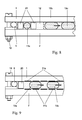
- FIG. 1 is first shown schematically a known type.
- a base plate 2 micro channels and cavities are incorporated, for example as in FIG. 1 schematically shown as a cross section through two adjacent channels 14a and 14b.
- the two fluid channels 14a and 14b are closed at the top by a common cover plate 1.
- This cover places high demands on a fluid-tight connection 3 of the base plate 2 with the cover plate 1.
- at the edges 15 there is a risk of ingress of sample fluid 10, if a capillary gap is created by an insufficient connection between cover plate 1 and base plate.
- the cover plate 1 is connected to the base plate 2, for example by gluing, again there is a risk of adhesive entering the channel 14a or 14b.
- FIG. 2 shows the inventive structure of the assembled and disassembled microfluidic system.
- a capillary gap which is filled with a sealing fluid 11 prevents the sample fluid 10 from entering the capillary gap between the base plate 2 and the cover plate 1.
- the sealing fluid 11 in this case is a nonpolar fluid. Due to the coating of the surface, the sample fluid 10 is not able to displace the nonpolar sealing fluid 11 from the capillary gap.
- the hydrophobic coatings of the surfaces are not necessary if the cover plate 1 and the base plate 2 are made of materials whose surfaces are hydrophobic per se.
- the coating of the facing surfaces of the cover plate 1 and the base plate 2 must be hydrophilic and the sealing fluid 11 must be a polar fluid.
- a sufficiently small capillary gap can for example already be produced by a sufficient roughness of the surfaces of the cover plate 1 and the base plate 2. Between the sealing fluid 11 and the sample fluid 10, a meniscus 16 is formed.
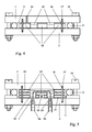
- FIG. 3 an overall structure of the system is shown.
- the base plate 2 and the cover plate 1 are flat.
- the formation of a channel structure is carried out in this example by a structured channel plate 20, which is advantageously made of a Teflon plate, in which the channel structure has been cut, for example by means of a laser.
- the channel plate must have hydrophobic (as in the case of Teflon) or hydrophilic surface properties.
- Fluid connection holes 7 in the base plate 2 provide a fluidic contact via hose connections 9.
- the actual channel system which in the embodiment according to Fig. 3 through the base plate 2, the cover plate 1 and the Channel plate 20 is formed, is closed by a peripheral seal 6, to prevent sealing fluid 11 flows through the capillary gap on the edges of the base plate 2 or cover plate 1 to the outside.
- the microfluidic system will, as in FIG. 4 shown as a cross section, compressed by clamping screws 19.
- the resulting width of the Kapillarspalte between the base plate 2 and the channel plate 20 and the cover plate 1 is first determined by the compression of the frame seal 6 and ultimately by the roughness of the plates.
- the mutually facing surfaces of the channel plate 20, cover plate 1 and base plate 2 can be roughened, so that sets a defined capillary gap.
- cover plate 1 and optionally existing channel plates 20 is filled with sealing fluid 11.
- a structured layer having a thickness which corresponds to the desired width of the capillary gap is applied to one or more of the plates 1, 2, 20 to 23 to produce a defined capillary gap between base plate 2, channel plate 20 and cover plate 1.
- the easy opening and closing of the microfluidic system by a screw or clamp connection is also a basis for an improved flooding of the channel structure.
- flooding is also possible with avoidance of air inclusions, especially in the case of complex microchannel structures changing channel cross-sections, chambers and partially hydrophobic and hydrophilic surfaces problematic.
- the inventive method proposes to make the mounting and clamping of the plates 1, 2 and 20 in a container filled with sealing fluid. Following this process, not only the capillary gaps between the individual plates 1, 2 and 20 are filled with sealing fluid, but also the fluid channels 14 themselves. After the closure of the microfluidic system by supplying sample fluid 10, the sealing fluid 11 contained in the channels 14 is displaced ,
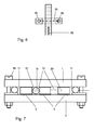
- FIG. 5 a further embodiment of the invention is shown.
- a plurality of structured channel plates 21, 22, 23 are superimposed.
- crossings of fluid paths in the manner of a multi-level printed circuit board can be produced.
- a fluid path 25 is considered in which a sample fluid 10 enters the microfluidic system at the hose connection 9a, passes through holes 7 in the channel plates 21 and 22 into the plane of the channel plate 23, in this plane the fluid path 26 in the plane of the channel plate 21 crosses and leaves the microfluidic system through hose connection 9b again.
- FIG. 5 described plate assembly proposes the inventive method to make the mounting and clamping of the plates 1, 2, 20 to 23 in a container filled with sealing fluid.
- FIG. 6 illustrates in a plan view of the course of the two intersecting fluid paths 25 and 26. This makes it possible to integrate even relatively complex channel structures with a variety of functions in a microfluidic system.
- FIG. 7 Another embodiment of the invention for a 2-phase fluidic system is disclosed in US Pat FIG. 7 shown.
- 2-phase fluidic systems are characterized by a segmented sample stream.
- a compartment 13, consisting of a polar fluid, for example, with entrapped organic or inorganic material is transported by means of a non-polar transport fluid 12 through the channel system. Due to the immiscibility of the transport fluid 12 and the sample fluid 10, stable microspheres formed by surface tension are formed.
- the sealing fluid 11 is in turn designed as a polar fluid whose wettability of the surfaces is higher than that of the likewise polar sample fluid 10.
- This embodiment assumes that the surfaces 5 of the base plate 2, channel plate 20 and cover plate 1 structured hydrophobic and hydrophilic coated are. In the actual channels 14a and 14b no wetting of the channel walls by the polar sample fluid 10 may be possible.
- Another advantage of the open design of the microfluidic system according to the invention is that such a structured coating is possible with reasonable effort.
- the transport fluid 12 of a 2-phase system is also used as a sealing fluid. Due to the high flow resistance in the narrow capillary gap with respect to the flow resistance in the actual channel 14, the overflow of transport fluid 12 through the capillary gap can be avoided, whereby the distance between successive compartments 13b and 13c remains constant.
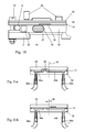
- the compartments are driven by a dielectrophoretic drive.
- cover plate 1 and base plate 2 are provided with electrode pairs 31a and 31b, which generate a changing (eg, wandering) electric field by a corresponding circuit and move the compartments 13a and 13b.
- the cover plate 1 is designed, for example, as a multi-level printed circuit board, which on the one hand carries electronic components such as amplifiers, AD converters or signal processors and electrically interconnects, on the other side on the fluid channels facing side sensor surfaces 35 with, for example, biologically active surfaces, pH sensors or other types of sensors wearing.
- the essence of the invention makes it possible to activate after the installation of the microfluidic system according to the invention, the defined sensors arranged, unless they were activated prior to assembly after assembly or to reactivate during the process duration. The same applies to, for example, the functionalization and calibration of the sensors.
- This exemplary illustration again shows the advantages of the microfluidic system according to the invention by combining an integrative, highly complex design with the property of simple assembly and disassembly.
- the base plate 2 or the cover plate 1 may be made of transparent material.
- this optical window 27 may be provided with a imaging feature in the form of a lens to achieve a high aperture. For example, an evaluation of compartments can take place through the optical window 27.
- a round base plate 52 is also provided with a round cover plate 51. Both the base plate 52 and the cover plate 51 are structured and contain different connection channels 54 and 55.
- the fluid flow of a sample fluid is, for example, from the connection tube 59a via the inflow channel 54a, the connection channel 55, the outflow channel 54b and the connecting tube 59b.
- the capillarity of the sealing fluid 11 in the gap between the base plate 52 and the cover plate 51 prevents leakage of the sample fluid at the junction between the base plate 52 and cover plate 51.
- FIG. 12 A wide embodiment of the fluid switch is in FIG. 12 shown.
- the fluid flow of a sample fluid is fed via a hose connection 61 to the microsystem, which again consists, for example, of a cover plate 51 and a base plate 52.
- the hose connection 61 is located in the axis 57, around which the base plate 52 can be rotated relative to the cover plate 51.
- the hose connection 62 in the base plate 51 which is connected via a hose connection 63 with a further hose connection 64.
- the hose connection 64 is located at a distance from the axis of rotation 57 and moves during rotation of the base plate 52 relative to the cover plate 51 on a circular arc.
- hose connections 65a to 65d At the same distance from the axis of rotation 57 are in the cover plate more hose connections 65a to 65d, such as FIG. 13 shows.
- a total of four hose connections 65a to 65d are provided, which are offset by 90 ° and have an equal distance from the axis of rotation 57 in the center of the circular base plate 52 and cover plate 51.
- the hose connection 64 now corresponds to one of the hose connections 65a to 65d, which can be assisted, for example, by a detent, then a fluidic connection is established for the fluid flow of the sample fluid to one of the selected hose connections 65a to 65d.
- different sample fluids can be supplied, one of which can be selected by turning the base plate 52 relative to the cover plate 51 and discharged through the drain hose 60.
- FIGS. 14 and 15 Another variant of a fluid switch is in the FIGS. 14 and 15 shown.
- the axis of rotation 57 of the circular cover and base plate 51 and 52 is again in alignment with the central hose connection 73, the here is arranged in a base plate 72.
- the base plate 72 In the base plate 72 are further, for example, four fluid ports 74a to 74d, which have an equal distance from the axis of rotation 57 and the hose connection 73.
- the cover plate 71 there is an angularly arranged connecting channel 76, which supplies position-dependent a sample flow supplied through the fluid connection 73 to two selected fluid connections 74a to 74d.
Abstract
Description
Die Erfindung betrifft ein Mikrofluidiksystem für das Erzeugen, Kultivieren, Manipulieren, Analysieren und Konservieren von einphasigen und mehrphasigen Fluiden im Mikromaßstab und ein Verfahren zur Flutung des Systems. Derartige Systeme werden u. a. für die Analyse organischer und anorganischer Substanzen, für chemische und biologische Prozesse, aber auch für die Kultivierung jeglicher Art von biologischen Zellen eingesetzt. Die verwendeten Fluide sind gasförmig oder flüssig. Mehrphasige Fluide werden u.a. benötigt, wenn Substanzen wie beispielsweise Probematerialien in beispielsweise durch Oberflächenspannungen oder chemische Reaktionen gebildete stabile Mikrosphären eingeschlossen werden und durch das Mikrofluidiksystem transportiert werden sollen. Der Transport von Substanzen kann auch in einphasigen Fluiden erfolgen.The invention relates to a microfluidic system for creating, cultivating, manipulating, analyzing and preserving monophasic and multiphase microfluidic fluids and a method of flooding the system. Such systems are u. a. used for the analysis of organic and inorganic substances, for chemical and biological processes, but also for the cultivation of any kind of biological cells. The fluids used are gaseous or liquid. Polyphase fluids are used i.a. when substances such as sample materials are to be entrapped in stable microspheres formed, for example, by surface tensions or chemical reactions and transported through the microfluidic system. The transport of substances can also take place in single-phase fluids.
Die Herstellung von Kanalstrukturen für Mikrofluidiksysteme setzt entsprechend präzise Fertigungstechnologien voraus, die zunächst der Halbleiterfertigung entlehnt wurden. Eingeführte Verfahren beruhen auf dem anisotropen oder isotropen Ätzen von Silizium mit anschließendem Deckeln der Kanalstruktur durch anodisches Bonden (
Bekannt ist auch die Herstellung der Kanalstrukturen durch Bearbeitung der Oberflächen von Kanalkörpern bestehend aus Kunststoffen, Metallen oder Gläsern mittels Laserablatation (u. a.
Zur Vermeidung von aufwändig herzustellenden Masken und Werkzeugen sind auch CNC-Verfahren bekannt, wie z.B. die Fräsbearbeitung von Glaskeramik oder Rapid-Prototyping-Verfahren.To avoid consuming masks and tools and CNC methods are known, such as. the milling of glass ceramic or rapid prototyping.
Das Deckeln der planar hergestellten Kanalstrukturen beispielsweise durch anodisches Bonden, Verklebung oder durch Verschweißen stellt hohe Anforderungen verbunden mit hohen Kosten an die entsprechenden Fertigungstechniken, sind doch einerseits Mikrospalte zwischen Kanalkörper und Abdeckplatte, andererseits auch das teilweise Verschließen von Mikrokanälen zu vermeiden.The lapping of the planar-made channel structures, for example, by anodic bonding, bonding or welding makes high demands associated with high costs of the corresponding manufacturing techniques, but on the one hand micro gaps between channel body and cover plate, on the other hand to avoid the partial closing of microchannels.
Das irreversible Deckeln der Kanalstruktur hat Nachteile. Die Reinigung der im Mikrosystem eingebrachten Kanäle ist nahezu unmöglich, sodass z. B. in Hinblick auf Querkontaminierungen das gesamte planare Mikrosystem als Einwegprodukt betrachtet werden sollte. Der Betrachtung als Einwegprodukt steht die zunehmende Komplexität des Mikrofluidiksystems gegenüber, das außer der eigentlichen Kanalstruktur auch fest integrierte Sensoren, Aktoren wie z. B. Pumpen und Ventile, passive Elemente wie Filter und Membranen sowie elektronische Baugruppen enthalten kann.The irreversible covering of the channel structure has disadvantages. The cleaning of introduced in the microsystem channels is almost impossible, so z. For example, with regard to cross contamination, the entire planar microsystem should be considered a disposable product. The consideration as a disposable product is contrasted with the increasing complexity of the microfluidic system, in addition to the actual channel structure and fixed integrated sensors, actuators such. As pumps and valves, passive elements such as filters and membranes and electronic assemblies may contain.
Hinzu kommt die Notwendigkeit, die Oberflächen des Mikrokanals hinsichtlich der Oberflächeneigenschaften zu funktionalisieren, was in geschlossenen Mikrokanälen aufwändig ist und die Zahl der Funktionalisierungstechniken stark limitiert. Außerdem ist die Kontrolle der Oberflächeneigenschaften nicht oder nur sehr eingeschränkt möglich.In addition, there is the need to functionalize the surfaces of the microchannel with respect to the surface properties, which is complicated in closed microchannels and greatly limits the number of functionalization techniques. In addition, the control of the surface properties is not possible or only to a very limited extent.
Eine solche Funktionalisierung besteht beispielsweise in der abschnittsweisen hydrophoben und hydrophilen Beschichtung von Kanalabschnitten, was insbesondere für mehrphasige Fluidströme notwendig ist. Solche Fluidströme bestehen im Wesentlichen aus sich abwechselnd wiederholenden Bereichen polarer und unpolarer Fluide, die aufgrund der unterschiedlichen Polaritäten eindeutige Phasengrenzen ausbilden und somit die Bildung von Mikrosphären erlauben. Die Applikation mehrphasiger Fluidströme in Mikrosystemen setzt voraus, dass alle Oberflächen des Mikrokanals für das Transportfluid des mehrphasigen Fluidstromes benetzbar sind und für die zweite Phase des mehrphasigen Fluidstromes, die Mikrosphäre, nicht benetzbar sind.Such a functionalization consists, for example, in the section-wise hydrophobic and hydrophilic coating of channel sections, which is necessary in particular for multiphase fluid flows. Such fluid streams consist essentially of alternately repeating regions of polar and non-polar fluids, which form distinct phase boundaries due to the different polarities and thus allow the formation of microspheres. The application of multiphase fluid streams in microsystems requires that all surfaces of the microchannel be wettable by the transport fluid of the multiphase fluid stream and not wettable to the second phase of the multiphase fluid stream, the microsphere.
In der
In der
Ferner ist in
Aufgabe der Erfindung ist es, eine Anordnung für ein leicht montier- und demontierbares Mikrofluidiksystem unter Vermeidung der oben genannten, dem Stand der Technik anhaftende Nachteile vorzuschlagen sowie ein Verfahren zur Flutung des Systems anzugeben.The object of the invention is to propose an arrangement for a readily assembled and disassembled microfluidic system while avoiding the above-mentioned, the prior art inherent disadvantages and to provide a method for flooding the system.
Die Aufgabe wird mit einer Vorrichtung mit den Merkmalen des Anspruchs 1 gelöst.The object is achieved with a device having the features of
Die Aufgabe wird auch durch ein Verfahren gemäß Anspruch 14 gelöst.The object is also achieved by a method according to claim 14.
Die Vorrichtung enthält einen Stapel von Platten, wobei mindestens eine Platte an seiner Oberfläche Vertiefungen für Kanäle enthält. Zwischen mindestens einer Deckplatte und mindestens einer mit den Kanälen versehenen Platte befindet sich ein Kapillarspalt, der mit einem Dichtfluid gefüllt ist, dessen Benetzungsfähigkeit gegenüber den Plattenoberflächen höher als die Benetzungsfähigkeit der Transport- und Probenfluide ist, die durch die Kanäle transportiert werden. Als Dichtfluid und als Transport- und Probenfluide können sowohl polar als auch unpolar ausgebildete Fluide verwendet werden.The device includes a stack of plates, at least one plate containing wells for channels on its surface. Between at least one cover plate and at least one plate provided with the channels is a capillary gap which is filled with a sealing fluid whose wetting ability with respect to the plate surfaces is higher than the wettability of the transport and sample fluids transported through the channels. As a sealing fluid and as transport and sample fluids, both polar and non-polar formed fluids can be used.
Eine vorteilhafte Ausgestaltung sieht vor, dass zwischen der Basis- und der Deckplatte eine oder mehrere Kanalplatten mit Ausformungen zur Durchleitung eines Proben- und/oder Transportfluids angeordnet sind.An advantageous embodiment provides that one or more channel plates with formations for the passage of a sample and / or transport fluid are arranged between the base and the cover plate.
Ferner ist es möglich, dass Mittel zum Ausrichten der Basis-, Deck- und/oder Kanalplatten vorhanden sind.Furthermore, it is possible that means for aligning the base, cover and / or channel plates are present.
Um die Basis- und Deckplatte und die dazwischen liegenden Kanalplatten miteinander zu verpressen, können Spannelemente verwendet werden.Clamping elements may be used to crimp the base and top plates and the channel plates therebetween.
Vorteilhaft ist es dabei, eine Rahmendichtung anzuordnen, welche die gesamte Kanalstruktur umgibt.It is advantageous to arrange a frame seal, which surrounds the entire channel structure.
Zum Befüllen des Dichtfluids können Füllöffnungen in der Basis- und Deckplatte angeordnet werden.For filling the sealing fluid filling openings can be arranged in the base and cover plate.
Ferner ist es möglich, dass mindestens eine der Basis- oder Deckplatte und/oder eine der dazwischen liegenden Kanalplatten aus transparentem Material besteht.Furthermore, it is possible that at least one of the base or cover plate and / or one of the intermediate channel plates is made of transparent material.
Das Dichtfluid kann so beschaffen sein, dass durch Zufuhr von Energie eine Zustandsänderung des Dichtfluids (z.B. Polymerisierung, Aushärtung) herbeigeführt werden kann, ohne die Dichteigenschaften des Dichtfluids und die Montierbarkeit/Demontierbarkeit des Mikrofluidiksystems zu beeinträchtigen. Dazu wird vor der Energiezufuhr das in den Mikrokanälen befindliche Dichtfluid mit einem mit diesem nicht mischbaren weiteren Fluid, dessen Zustand durch Zufuhr von Energie nicht verändert wird, entfernt. Danach wird die Energie für die Zustandsänderung des Dichtfluids zugeführt.The sealing fluid may be such that, by the application of energy, a change in state of the sealing fluid (e.g., polymerization, curing) may be induced without compromising the sealing properties of the sealing fluid and the mountability / disassembly of the microfluidic system. For this purpose, the sealing fluid located in the microchannels is removed before the energy supply with a further fluid immiscible with this, whose state is not changed by the supply of energy. Thereafter, the energy for the change in state of the sealing fluid is supplied.
Eine weitere vorteilhafte Ausführung sieht vor, dass mindestens eine der Basis- oder Deckplatte und/oder eine der dazwischen liegenden Kanalplatten partiell hydrophile und partiell hydrophobe Oberflächeneigenschaften besitzt.A further advantageous embodiment provides that at least one of the base or cover plate and / or one of the intermediate channel plates has partially hydrophilic and partially hydrophobic surface properties.
Es ist auch möglich, dass mindestens eine der Basis- oder Deckplatten und/oder eine der dazwischen liegenden Kanalplatten aktive und passive Funktionselemente sowie fluidische Anschlüsse enthalten.It is also possible that at least one of the base or cover plates and / or one of the intermediate channel plates contain active and passive functional elements as well as fluidic connections.
Die aktiven und passiven Funktionselemente können funktionalisiert sein, z.B. mit funktionellen Substanzen wie Antikörpern, Antigenen etc. oder hydrophob oder hydrophil beschichtet sein.The active and passive functional elements may be functionalised, e.g. be coated with functional substances such as antibodies, antigens etc. or hydrophobic or hydrophilic.
Im Kanal können sich Partikel befinden, die funktionalisiert sind und die durch Zuführung von Energie (z.B. von magnetischer Energie) an einem definierten Ort im Kanal fixiert werden können. Durch Verringerung der Energie kann die Fixierung der Partikel gelöst und diese im Kanal weitertransportiert werden.The channel may contain particles which are functionalized and which may be fixed by supplying energy (e.g., magnetic energy) at a defined location in the channel. By reducing the energy, the fixation of the particles can be solved and these are transported on in the channel.
Vorteilhaft ist es weiter, dass die Oberflächen der Basis- oder Deckplatte und/oder eine der dazwischen liegenden Kanalplatten mit einer Rauigkeit versehen sind, sodass beim Zusammenpressen der Basis- und Deckplatte und einer der dazwischen liegenden Kanalplatten Kapillarspalte definierter Weite entstehen.It is also advantageous that the surfaces of the base or cover plate and / or one of the intermediate channel plates are provided with a roughness, so that upon compression of the base and cover plate and one of the intermediate channel plates capillary gaps of defined width arise.
Eine weitere Ausführung der Erfindung ermöglicht es, die Anordnung als fluidischen Schalter zu verwenden, wobei ein oder mehrere eingangsseitige Fluidströme ein oder mehreren Ausgangskanälen zugeordnet werden können. Der Stapel von Platten, bei dem Kanäle für den Transport von Fluiden durch ein Dichtfluid in einem Kapillarspalt abgedichtet werden, bietet die Möglichkeit, durch Verschieben oder Verdrehen der Platten gegeneinander Schaltfunktionen für die Zuführung und Abführung von Fluidströmen auszubilden.Another embodiment of the invention makes it possible to use the arrangement as a fluidic switch, wherein one or more input-side fluid streams can be assigned to one or more output channels. The stack of plates, in which channels for the transport of fluids are sealed by a sealing fluid in a capillary gap, offers the possibility of forming by switching or rotation of the plates against each other switching functions for the supply and discharge of fluid streams.
Mikrofluidiksysteme zur Analyse von Proben bzw. zur Durchführung chemischer Reaktionen besitzen meist mehrere Betriebszustände. Proben- und Wirkstoffströme müssen in wechselnden Zuordnungen durch Ventile ein- und ausgeschaltet werden. Bekannte Mikroventile, die in ein Mikrofluidiksystem integriert werden können, sind relativ kostenaufwändig und für eine Reinigung schwer zugänglich.Microfluidic systems for analyzing samples or carrying out chemical reactions usually have several operating states. Sample and active substance flows must be switched on and off in changing allocations by valves. Known microvalves that can be integrated into a microfluidic system are relatively expensive and difficult to access for cleaning.
Ein einfaches System zum Schalten der Fluide ist die örtlich begrenzte Viskositätsveränderung eines Fluids im Kanal durch Energieeintrag. Dieser Vorgang ist reversibel. Somit sind keine zusätzlichen Schaltelemente notwendig.A simple system for switching the fluids is the localized viscosity change of a fluid in the channel due to energy input. This process is reversible. Thus, no additional switching elements are necessary.
Alle Elemente des erfindungsgemäßen Mikrofluidiksystems können aus Materialien bestehen, die desinfizierbar oder sterilisierbar, z B. autoklavierbar sind. Es ist möglich, das Mikrofluidiksystem im montierten Zustand zu desinfizieren oder zu sterilisieren, z B. zu autoklavieren. Es ist auch möglich, die einzelnen Elemente des Mikrofluidiksystems zu desinfizieren oder zu sterilisieren, z B. zu autoklavieren, und diese dann beispielsweise unter sterilen Verhältnissen einer Sterilwerkbank zum vollständigen Mikrofluidiksystem zusammenzusetzen.All elements of the microfluidic system according to the invention may consist of materials which can be disinfected or sterilized, for example autoclavable. It is possible to disinfect or sterilize the microfluidic system in the assembled state, for example to autoclave. It is also possible to disinfect or sterilize the individual elements of the microfluidic system, for example to autoclave, and then to assemble them, for example, under sterile conditions of a sterile workbench to complete microfluidic system.
Das Fluten des Mikrofluidiksystems erfolgt beispielsweise dadurch, dass das Mikrofluidiksystem im demontierten Zustand in einen Behälter mit Dichtfluid getaucht wird, unter Luftabschluss die Basis- und Deckplatte und zwischen liegende Kanalplatten ausgerichtet und mit einander verspannt werden und dass nach dem Verspannen des Mikrofluidiksystems und Herstellung der fluidischen Anschlüsse die in den Kanälen befindliche Dichtfluid durch Proben- oder Transportfluid ersetzt wird.The flooding of the microfluidic system takes place, for example, by virtue of the fact that the microfluidic system is immersed in a container with sealing fluid in the disassembled state, the base and cover plates and intermediate channel plates are aligned and braced with each other under tension and that after clamping the microfluidic system and production of the fluidic Connections the sealing fluid in the channels is replaced by sample or transport fluid.
Die Erfindung soll anhand von Ausführungsbeispielen beschrieben werden. DieThe invention will be described with reference to exemplary embodiments. The
Es zeigen
Figur 1- den schematischen Aufbau bekannter Mikrofluidiksysteme,
Figur 2- den schematischen Aufbau des erfindungsgemäßen Mikrofluidiksystems,
Figur 3- den Gesamtaufbau in perspektivischer Darstellung,
Figur 4- einen Aufbau mit Kanalplatte,
Figur 5- einen Aufbau mit mehreren Fluidführungsebenen,
Figur 6- eine Kanalkreuzung,
Figur 7- eine 3-Fluid-System,
Figur 8- die Führung von Kompartimenten,
Figur 9- einen elektrokinetischen Antrieb von Kompartimenten,
Figur 10- eine Anordnung mit Sensoren und optischem Fenster,
- Figur 11a
- eine Ausführung als Fluidschalter im eingeschalteten Zustand,
- Figur 11b
- eine Ausführung als Fluidschalter im gesperrten Zustand,
Figur 12- einen Fluidschalter mit einem Eingang und mehreren Ausgängen,
Figur 13- die Draufsicht auf den Schnitt A-A in
Figur 12 - Figur 14
- einen Fluidschalter mit einem Eingang und zwei wechselbaren Ausgängen
- und Figur 15
- einen Verbindungskanal im Fluidschalter nach
Figur 14 .
- FIG. 1
- the schematic structure of known microfluidic systems,
- FIG. 2
- the schematic structure of the microfluidic system according to the invention,
- FIG. 3
- the overall structure in perspective,
- FIG. 4
- a structure with channel plate,
- FIG. 5
- a construction with several fluid guide levels,
- FIG. 6
- a channel intersection,
- FIG. 7
- a 3-fluid system,
- FIG. 8
- the leadership of compartments,
- FIG. 9
- an electrokinetic drive of compartments,
- FIG. 10
- an arrangement with sensors and optical window,
- FIG. 11a
- an embodiment as a fluid switch in the on state,
- FIG. 11b
- an embodiment as a fluid switch in the locked state,
- FIG. 12
- a fluid switch with one input and several outputs,
- FIG. 13
- the top view of the section AA in
FIG. 12 . - FIG. 14
- a fluid switch with one input and two exchangeable outputs
- and FIG. 15
- a connection channel in the fluid switch after
FIG. 14 ,
In
Es entspricht dem Wesen der Erfindung, dass, wenn das Probenfluid ein unpolares Fluid ist, die Beschichtung der einander zugewandten Oberflächen der Deckplatte 1 und der Basisplatte 2 hydrophil und das Dichtfluid 11 ein polares Fluid sein muss.It is in accordance with the essence of the invention that when the sample fluid is a non-polar fluid, the coating of the facing surfaces of the
Je kleiner der Kapillarspalt ist, desto größer kann der Druckunterschied zwischen den beiden Kanälen 14a und 14b sein, ohne dass ein Übertreten von Probenfluid 10 von einem auf den anderen Kanal erfolgen kann. Ein hinreichend kleiner Kapillarspalt kann beispielsweise bereits durch eine ausreichende Rauigkeit der Oberflächen von Deckplatte 1 und der Basisplatte 2 erzeugt werden. Zwischen dem Dichtfluid 11 und dem Probenfluid 10 bildet sich ein Meniskus 16 aus.The smaller the capillary gap is, the larger the pressure difference between the two
In
Das Mikrofluidiksystem wird, wie in
In einer weiteren Ausführung der Erfindung wird zur Herstellung eines definierten Kapillarspaltes zwischen Basisplatte 2, Kanalplatte 20 und Deckplatte 1 eine strukturierte Schicht mit einer Dicke, die der gewünschten Weite des Kapillarspaltes entspricht auf eine oder mehrere der Platten 1, 2, 20 bis 23 aufgebracht.In a further embodiment of the invention, a structured layer having a thickness which corresponds to the desired width of the capillary gap is applied to one or more of the
Durch Lösen der Spannschrauben 19 kann das Mikrofluidiksystem wieder geöffnet werden. Damit ergeben sich viele Möglichkeiten der Reinigung, des Austausches einzelner Komponenten und der Regenerierung von Oberflächenmodifikationen. Zur Ausrichtung der einzelnen Platten 1, 2, 20 werden im Ausführungsbeispiel Passstifte 18 verwendet, die in Passbohrungen 17 geführt werden.By loosening the clamping screws 19, the microfluidic system can be opened again. This results in many possibilities for cleaning, the replacement of individual components and the regeneration of surface modifications. For alignment of the
Das einfache Öffnen und Schließen des Mikrofluidiksystems durch eine Schraub- oder Klemmverbindung ist gleichzeitig eine Grundlage für eine verbesserte Flutung der Kanalstruktur. Wie bekannt ist die Flutung unter Vermeidung von Lufteinschlüssen insbesondere bei komplexen Mikrokanalstrukturen auch mit wechselnden Kanalquerschnitten, Kammern und partiell hydrophoben und hydrophilen Oberflächen problematisch. Das erfindungsgemäße Verfahren schlägt vor, das Montieren und Verspannen der Platten 1, 2 und 20 in einem Behälter mit gefülltem Dichtfluid vorzunehmen. Im Anschluss an diesem Vorgang sind nicht nur die Kapillarspalten zwischen den einzelnen Platten 1, 2 und 20 mit Dichtfluid gefüllt, sondern auch die Fluidkanäle 14 selbst. Nach dem Verschluss des Mikrofluidiksystems wird durch Zuführung von Probenfluid 10 die in den Kanälen 14 befindliche Dichtfluid 11 verdrängt.The easy opening and closing of the microfluidic system by a screw or clamp connection is also a basis for an improved flooding of the channel structure. As is known, flooding is also possible with avoidance of air inclusions, especially in the case of complex microchannel structures changing channel cross-sections, chambers and partially hydrophobic and hydrophilic surfaces problematic. The inventive method proposes to make the mounting and clamping of the
In
Eine weitere Ausführung der Erfindung für ein 2-Phasen-Fluidiksystem wird in
Auf ein gesondertes Dichtfluid kann verzichtet werden, wenn, wie in
In einer weiteren in
In
Die Basisplatte 2 oder die Deckplatte 1 kann aus transparentem Material ausgeführt sein. In einer anderen Ausführungsvariante kann aber auch ein optisches Fenster 27, wie in
Für die Ausführung von Schaltfunktionen von Fluidströmen im erfindungsgemäßen Mikrofluidiksystem werden mindestens eine der Basis- oder Deckplatte oder mindestens eine der Kanalplatten gegeneinander verschoben oder verdreht. Bei der in
Eine weite Ausführungsform des Fluidschalters ist in
Eine weitere Ausführungsvariante eines Fluidschalters ist in den
- 11
- Deckplattecover plate
- 22
- Basisplattebaseplate
- 33
- Fluiddichte VerbindungFluid-tight connection
- 44
- Hydrophobe BeschichtungHydrophobic coating
- 55
- Hydrophile BeschichtungHydrophilic coating
- 66
- Rahmendichtungweatherstrip
- 77
- Fluid - AnschlusslöcherFluid connection holes
- 88th
- Fluidkanälefluid channels
- 99
- Schlauchanschlüssehose connections
- 1010
- Probenfluidsample fluid
- 1111
- Dichtfluidsealing fluid
- 1212
- Transportfluidtransport fluid
- 1313
- Kompartimentecompartments
- 1414
- Fluidkanälefluid channels
- 1515
- Kanteedge
- 1616
- Meniskusmeniscus
- 1717
- Passbohrungfitting bore
- 1818
- Passstiftdowel
- 1919
- Spannschraubenturnbuckles
- 2020
- Kanalplattechannel plate
- 2121
- Kanalplatte AChannel plate A
- 2222
- Kanalplatte BChannel plate B
- 2323
- Kanalplatte CChannel plate C
- 2424
- Füllöffnungenfilling openings
- 2525
- Fluidpfad AFluid path A
- 2626
- Fluidpfadfluid path
- 2727
- Optisches FensterOptical window
- 3030
- Elektronische BauelementeElectronic Components
- 3131
- Elektrodenelectrodes
- 3232
- Leiterplattenebene APCB level A
- 3333
- Leiterplattenebene BPCB level B
- 3434
- Leiterplattenebene CPCB level C
- 3535
- Sensorsensor
- 5151
- Deckplatte des FluidschaltersCover plate of the fluid switch
- 5252
- Basisplatte des FluidschaltersBase plate of the fluid switch
- 54a54a
- Zuflusskanalinlet channel
- 54b54b
- Abflusskanalspillway
- 5555
- Verbindungskanalconnecting channel
- 5757
- Achseaxis
- 5959
- Verbindungsschlauchconnecting hose
- 6060
- Abflussschlauchdrain hose
- 61...6561 ... 65
- Schlauchanschlusshose connection
- 6666
- Verbindungsschlauclever connection
- 7171
- Deckplatte, kreisförmigCover plate, circular
- 7272
- Basisplatte, kreisförmigBase plate, circular
- 7373
- Fluidanschluss für ZuführungFluid connection for supply
- 7474
- Fluidanschluss für AbflussFluid connection for drain
- 7676
- Verbindungskanalconnecting channel
Claims (14)
Applications Claiming Priority (2)
| Application Number | Priority Date | Filing Date | Title |
|---|---|---|---|
| DE102009020449 | 2009-05-08 | ||
| DE102009024048A DE102009024048B3 (en) | 2009-05-08 | 2009-06-05 | Mountable and demountable microfluidic system used for producing, cultivating, manipulating, analyzing and preserving single-phase and multiphase fluids, comprises stack of plates |
Publications (2)
| Publication Number | Publication Date |
|---|---|
| EP2248588A1 true EP2248588A1 (en) | 2010-11-10 |
| EP2248588B1 EP2248588B1 (en) | 2015-07-08 |
Family
ID=42338966
Family Applications (1)
| Application Number | Title | Priority Date | Filing Date |
|---|---|---|---|
| EP10162009.4A Not-in-force EP2248588B1 (en) | 2009-05-08 | 2010-05-05 | Mountable and dismountable microfluid system and method for flooding the system |
Country Status (2)
| Country | Link |
|---|---|
| EP (1) | EP2248588B1 (en) |
| DE (1) | DE102009024048B3 (en) |
Cited By (4)
| Publication number | Priority date | Publication date | Assignee | Title |
|---|---|---|---|---|
| CN103313794A (en) * | 2010-11-30 | 2013-09-18 | 康宁股份有限公司 | Direct sealing of glass microstructures |
| CN113710352A (en) * | 2019-01-31 | 2021-11-26 | 赛普公司 | Microfluidic device and method for providing double emulsion droplets |
| DE102021116887A1 (en) | 2021-06-30 | 2023-01-05 | Institut für Bioprozess- und Analysenmesstechnik e.V. | Arrangement for generating fluid sequences in a multi-fluid transport channel for conditioning and detecting the fluid sequences generated in the multi-fluid transport channel |
| US11565261B2 (en) | 2018-03-27 | 2023-01-31 | Robert Bosch Gmbh | Method and microfluidic device for aliquoting a sample liquid using a sealing liquid, method for producing a microfluidic device and microfluidic system |
Families Citing this family (4)
| Publication number | Priority date | Publication date | Assignee | Title |
|---|---|---|---|---|
| CN105408735A (en) * | 2013-07-03 | 2016-03-16 | 怀亚特技术公司 | Method and apparatus to control sample carryover in analytical instruments |
| DE102017211451B4 (en) * | 2017-07-05 | 2019-03-21 | Robert Bosch Gmbh | Micromechanical sensor device and corresponding manufacturing method |
| CN110252221A (en) * | 2019-05-19 | 2019-09-20 | 南京汇科高分子材料有限公司 | For producing the reaction kettle of modified isocyanate |
| WO2023107123A1 (en) * | 2021-12-10 | 2023-06-15 | Hewlett-Packard Development Company, L.P. | Microfluidic devices with dielectrophoretic actuators |
Citations (13)
| Publication number | Priority date | Publication date | Assignee | Title |
|---|---|---|---|---|
| DE69114838T2 (en) | 1990-05-10 | 1996-06-05 | Pharmacia Biotech Ab | MICROSTRUCTURE FOR FLUIDS AND METHOD FOR THEIR PRODUCTION. |
| US5571410A (en) | 1994-10-19 | 1996-11-05 | Hewlett Packard Company | Fully integrated miniaturized planar liquid sample handling and analysis device |
| DE19648695C2 (en) | 1996-11-25 | 1999-07-22 | Abb Patent Gmbh | Device for the automatic and continuous analysis of liquid samples |
| US5964239A (en) | 1996-05-23 | 1999-10-12 | Hewlett-Packard Company | Housing assembly for micromachined fluid handling structure |
| US6399394B1 (en) * | 1999-06-30 | 2002-06-04 | Agilent Technologies, Inc. | Testing multiple fluid samples with multiple biopolymer arrays |
| US6450203B1 (en) | 2000-07-07 | 2002-09-17 | Micralyne Inc. | Sealed microfluidic devices |
| WO2003062133A2 (en) * | 2002-01-18 | 2003-07-31 | Avery Dennison Corporation | Covered microchamber structures |
| US20030165079A1 (en) | 2001-12-11 | 2003-09-04 | Kuan Chen | Swirling-flow micro mixer and method |
| DE19927533B4 (en) | 1999-06-16 | 2004-03-04 | Merck Patent Gmbh | Miniaturized analysis system |
| US20050226771A1 (en) * | 2003-09-19 | 2005-10-13 | Lehto Dennis A | High speed microplate transfer |
| US20050272142A1 (en) * | 2004-04-14 | 2005-12-08 | Hitachi Maxwell, Ltd. | Fluid vessel |
| WO2006046164A1 (en) * | 2004-10-27 | 2006-05-04 | Koninklijke Philips Electronics N. V. | Fluid container composed of two plates |
| US20090224482A1 (en) * | 2008-03-04 | 2009-09-10 | Life Technologies Corporation | Custom Flow Cell Gasket and Assemblies and Methods Thereof |
Family Cites Families (3)
| Publication number | Priority date | Publication date | Assignee | Title |
|---|---|---|---|---|
| JP3746766B2 (en) * | 2001-02-23 | 2006-02-15 | 独立行政法人科学技術振興機構 | Emulsion production method and apparatus |
| US7927797B2 (en) * | 2004-01-28 | 2011-04-19 | 454 Life Sciences Corporation | Nucleic acid amplification with continuous flow emulsion |
| DE102006053451B4 (en) * | 2006-11-11 | 2008-11-27 | Microfluidic Chipshop Gmbh | Microfluidic platform for temperature control of substances and / or for reactions to be tempered |
-
2009
- 2009-06-05 DE DE102009024048A patent/DE102009024048B3/en not_active Expired - Fee Related
-
2010
- 2010-05-05 EP EP10162009.4A patent/EP2248588B1/en not_active Not-in-force
Patent Citations (13)
| Publication number | Priority date | Publication date | Assignee | Title |
|---|---|---|---|---|
| DE69114838T2 (en) | 1990-05-10 | 1996-06-05 | Pharmacia Biotech Ab | MICROSTRUCTURE FOR FLUIDS AND METHOD FOR THEIR PRODUCTION. |
| US5571410A (en) | 1994-10-19 | 1996-11-05 | Hewlett Packard Company | Fully integrated miniaturized planar liquid sample handling and analysis device |
| US5964239A (en) | 1996-05-23 | 1999-10-12 | Hewlett-Packard Company | Housing assembly for micromachined fluid handling structure |
| DE19648695C2 (en) | 1996-11-25 | 1999-07-22 | Abb Patent Gmbh | Device for the automatic and continuous analysis of liquid samples |
| DE19927533B4 (en) | 1999-06-16 | 2004-03-04 | Merck Patent Gmbh | Miniaturized analysis system |
| US6399394B1 (en) * | 1999-06-30 | 2002-06-04 | Agilent Technologies, Inc. | Testing multiple fluid samples with multiple biopolymer arrays |
| US6450203B1 (en) | 2000-07-07 | 2002-09-17 | Micralyne Inc. | Sealed microfluidic devices |
| US20030165079A1 (en) | 2001-12-11 | 2003-09-04 | Kuan Chen | Swirling-flow micro mixer and method |
| WO2003062133A2 (en) * | 2002-01-18 | 2003-07-31 | Avery Dennison Corporation | Covered microchamber structures |
| US20050226771A1 (en) * | 2003-09-19 | 2005-10-13 | Lehto Dennis A | High speed microplate transfer |
| US20050272142A1 (en) * | 2004-04-14 | 2005-12-08 | Hitachi Maxwell, Ltd. | Fluid vessel |
| WO2006046164A1 (en) * | 2004-10-27 | 2006-05-04 | Koninklijke Philips Electronics N. V. | Fluid container composed of two plates |
| US20090224482A1 (en) * | 2008-03-04 | 2009-09-10 | Life Technologies Corporation | Custom Flow Cell Gasket and Assemblies and Methods Thereof |
Cited By (7)
| Publication number | Priority date | Publication date | Assignee | Title |
|---|---|---|---|---|
| CN103313794A (en) * | 2010-11-30 | 2013-09-18 | 康宁股份有限公司 | Direct sealing of glass microstructures |
| CN103313794B (en) * | 2010-11-30 | 2015-07-29 | 康宁股份有限公司 | The direct sealing of silica micro structure |
| US11565261B2 (en) | 2018-03-27 | 2023-01-31 | Robert Bosch Gmbh | Method and microfluidic device for aliquoting a sample liquid using a sealing liquid, method for producing a microfluidic device and microfluidic system |
| CN113710352A (en) * | 2019-01-31 | 2021-11-26 | 赛普公司 | Microfluidic device and method for providing double emulsion droplets |
| CN113710352B (en) * | 2019-01-31 | 2024-03-26 | 赛普公司 | Microfluidic device and method for providing dual emulsion droplets |
| DE102021116887A1 (en) | 2021-06-30 | 2023-01-05 | Institut für Bioprozess- und Analysenmesstechnik e.V. | Arrangement for generating fluid sequences in a multi-fluid transport channel for conditioning and detecting the fluid sequences generated in the multi-fluid transport channel |
| EP4122604A2 (en) | 2021-06-30 | 2023-01-25 | Institut für Bioprozess- und Analysenmesstechnik e.V. | Arrangement and method for generating fluid sequences in a multi-fluid transport channel and for conditioning and detecting the fluid sequences generated in the multi-fluid transport channel |
Also Published As
| Publication number | Publication date |
|---|---|
| EP2248588B1 (en) | 2015-07-08 |
| DE102009024048B3 (en) | 2010-08-19 |
Similar Documents
| Publication | Publication Date | Title |
|---|---|---|
| EP2248588B1 (en) | Mountable and dismountable microfluid system and method for flooding the system | |
| EP2576065B1 (en) | Flow cell with cavity and diaphragm | |
| DE10227593B4 (en) | Flow circuit microdevices | |
| EP2821138B2 (en) | Flow cell with integrated dry substance | |
| EP2389529B1 (en) | Valve, in particular for a component in microfluid technology | |
| EP1144095B1 (en) | Device for concentrating and/or purifying macromolecules in a solution and method for producing such a device | |
| DE60208235T2 (en) | MICROFLUIDIC DEVICES WITH DISTRIBUTION ENCLOSURES | |
| EP2796200B1 (en) | Microfluid analysis cartridge and method for its fabrication | |
| AT519382B1 (en) | Device with rotary valve for the manipulation of liquids | |
| DE102011078961A1 (en) | System for separating constituents such as blood plasma from blood sample, has filter layer arranged between substrates for separating the constituents of sample in one cavity and for discharging separated constituents to other cavity | |
| DE19933458A1 (en) | Device for handling liquid samples, system for handling liquid samples and method for producing the device | |
| EP1062042A1 (en) | Sample support | |
| EP2308589B1 (en) | Microfluid structure | |
| DE102004063438A1 (en) | Novel microfluidic sample carriers | |
| DE102009015395A1 (en) | Micro fluid cell, for analysis and diagnosis of e.g. blood, has a pressure zone to transport the fluid through channels to chambers containing reagents and through a detection chamber | |
| EP3049186B1 (en) | Analytical device for performing pcr, method for operating the device and method of making the device | |
| EP1489404A1 (en) | Method for producing a 3-D microscope flowcell | |
| DE102009001257A1 (en) | Apparatus and method for handling liquids | |
| WO2010031559A1 (en) | Microfluidic valve, microfluidic pump, microfluidic system, and a production method | |
| EP2754495A2 (en) | Microfluidic channel system with bubble capture device and method for the removal of gas bubbles | |
| EP2522427B1 (en) | Micro-fluid device and method for manufacturing the same | |
| EP2525225B1 (en) | Device and method for examining differentiation of cells | |
| DE102014202342A1 (en) | Device for pre-storing a fluid in a microfluidic system, method for operating and method for producing such a device | |
| DE202014104510U1 (en) | Device for pre-storing a fluid in a microfluidic system | |
| DE19922075A1 (en) | Bonding two microstructured plastics workpieces together, comprises introducing a plastics-dissolving organic solvent into a groove between the workpieces |
Legal Events
| Date | Code | Title | Description |
|---|---|---|---|
| PUAI | Public reference made under article 153(3) epc to a published international application that has entered the european phase |
Free format text: ORIGINAL CODE: 0009012 |
|
| AK | Designated contracting states |
Kind code of ref document: A1 Designated state(s): AL AT BE BG CH CY CZ DE DK EE ES FI FR GB GR HR HU IE IS IT LI LT LU LV MC MK MT NL NO PL PT RO SE SI SK SM TR |
|
| AX | Request for extension of the european patent |
Extension state: BA ME RS |
|
| 17P | Request for examination filed |
Effective date: 20110225 |
|
| 17Q | First examination report despatched |
Effective date: 20120711 |
|
| GRAP | Despatch of communication of intention to grant a patent |
Free format text: ORIGINAL CODE: EPIDOSNIGR1 |
|
| INTG | Intention to grant announced |
Effective date: 20150323 |
|
| RIN1 | Information on inventor provided before grant (corrected) |
Inventor name: WIEDEMEIER, STEFAN Inventor name: LEMKE, KAREN Inventor name: GASTROCK, GUNTER Inventor name: GRODRIAN, ANDREAS Inventor name: ROEMER, ROBERT |
|
| GRAS | Grant fee paid |
Free format text: ORIGINAL CODE: EPIDOSNIGR3 |
|
| GRAA | (expected) grant |
Free format text: ORIGINAL CODE: 0009210 |
|
| AK | Designated contracting states |
Kind code of ref document: B1 Designated state(s): AL AT BE BG CH CY CZ DE DK EE ES FI FR GB GR HR HU IE IS IT LI LT LU LV MC MK MT NL NO PL PT RO SE SI SK SM TR |
|
| REG | Reference to a national code |
Ref country code: GB Ref legal event code: FG4D Free format text: NOT ENGLISH |
|
| REG | Reference to a national code |
Ref country code: AT Ref legal event code: REF Ref document number: 734941 Country of ref document: AT Kind code of ref document: T Effective date: 20150715 Ref country code: CH Ref legal event code: EP |
|
| REG | Reference to a national code |
Ref country code: IE Ref legal event code: FG4D Free format text: LANGUAGE OF EP DOCUMENT: GERMAN |
|
| REG | Reference to a national code |
Ref country code: DE Ref legal event code: R096 Ref document number: 502010009806 Country of ref document: DE |
|
| REG | Reference to a national code |
Ref country code: NL Ref legal event code: MP Effective date: 20150708 |
|
| REG | Reference to a national code |
Ref country code: LT Ref legal event code: MG4D |
|
| PG25 | Lapsed in a contracting state [announced via postgrant information from national office to epo] |
Ref country code: GR Free format text: LAPSE BECAUSE OF FAILURE TO SUBMIT A TRANSLATION OF THE DESCRIPTION OR TO PAY THE FEE WITHIN THE PRESCRIBED TIME-LIMIT Effective date: 20151009 Ref country code: LV Free format text: LAPSE BECAUSE OF FAILURE TO SUBMIT A TRANSLATION OF THE DESCRIPTION OR TO PAY THE FEE WITHIN THE PRESCRIBED TIME-LIMIT Effective date: 20150708 Ref country code: LT Free format text: LAPSE BECAUSE OF FAILURE TO SUBMIT A TRANSLATION OF THE DESCRIPTION OR TO PAY THE FEE WITHIN THE PRESCRIBED TIME-LIMIT Effective date: 20150708 Ref country code: FI Free format text: LAPSE BECAUSE OF FAILURE TO SUBMIT A TRANSLATION OF THE DESCRIPTION OR TO PAY THE FEE WITHIN THE PRESCRIBED TIME-LIMIT Effective date: 20150708 Ref country code: NO Free format text: LAPSE BECAUSE OF FAILURE TO SUBMIT A TRANSLATION OF THE DESCRIPTION OR TO PAY THE FEE WITHIN THE PRESCRIBED TIME-LIMIT Effective date: 20151008 |
|
| PG25 | Lapsed in a contracting state [announced via postgrant information from national office to epo] |
Ref country code: PL Free format text: LAPSE BECAUSE OF FAILURE TO SUBMIT A TRANSLATION OF THE DESCRIPTION OR TO PAY THE FEE WITHIN THE PRESCRIBED TIME-LIMIT Effective date: 20150708 Ref country code: HR Free format text: LAPSE BECAUSE OF FAILURE TO SUBMIT A TRANSLATION OF THE DESCRIPTION OR TO PAY THE FEE WITHIN THE PRESCRIBED TIME-LIMIT Effective date: 20150708 Ref country code: PT Free format text: LAPSE BECAUSE OF FAILURE TO SUBMIT A TRANSLATION OF THE DESCRIPTION OR TO PAY THE FEE WITHIN THE PRESCRIBED TIME-LIMIT Effective date: 20151109 Ref country code: IS Free format text: LAPSE BECAUSE OF FAILURE TO SUBMIT A TRANSLATION OF THE DESCRIPTION OR TO PAY THE FEE WITHIN THE PRESCRIBED TIME-LIMIT Effective date: 20151108 Ref country code: ES Free format text: LAPSE BECAUSE OF FAILURE TO SUBMIT A TRANSLATION OF THE DESCRIPTION OR TO PAY THE FEE WITHIN THE PRESCRIBED TIME-LIMIT Effective date: 20150708 Ref country code: SE Free format text: LAPSE BECAUSE OF FAILURE TO SUBMIT A TRANSLATION OF THE DESCRIPTION OR TO PAY THE FEE WITHIN THE PRESCRIBED TIME-LIMIT Effective date: 20150708 |
|
| REG | Reference to a national code |
Ref country code: DE Ref legal event code: R097 Ref document number: 502010009806 Country of ref document: DE |
|
| PG25 | Lapsed in a contracting state [announced via postgrant information from national office to epo] |
Ref country code: DK Free format text: LAPSE BECAUSE OF FAILURE TO SUBMIT A TRANSLATION OF THE DESCRIPTION OR TO PAY THE FEE WITHIN THE PRESCRIBED TIME-LIMIT Effective date: 20150708 Ref country code: EE Free format text: LAPSE BECAUSE OF FAILURE TO SUBMIT A TRANSLATION OF THE DESCRIPTION OR TO PAY THE FEE WITHIN THE PRESCRIBED TIME-LIMIT Effective date: 20150708 Ref country code: SK Free format text: LAPSE BECAUSE OF FAILURE TO SUBMIT A TRANSLATION OF THE DESCRIPTION OR TO PAY THE FEE WITHIN THE PRESCRIBED TIME-LIMIT Effective date: 20150708 Ref country code: IT Free format text: LAPSE BECAUSE OF FAILURE TO SUBMIT A TRANSLATION OF THE DESCRIPTION OR TO PAY THE FEE WITHIN THE PRESCRIBED TIME-LIMIT Effective date: 20150708 Ref country code: CZ Free format text: LAPSE BECAUSE OF FAILURE TO SUBMIT A TRANSLATION OF THE DESCRIPTION OR TO PAY THE FEE WITHIN THE PRESCRIBED TIME-LIMIT Effective date: 20150708 |
|
| PLBE | No opposition filed within time limit |
Free format text: ORIGINAL CODE: 0009261 |
|
| STAA | Information on the status of an ep patent application or granted ep patent |
Free format text: STATUS: NO OPPOSITION FILED WITHIN TIME LIMIT |
|
| REG | Reference to a national code |
Ref country code: FR Ref legal event code: PLFP Year of fee payment: 7 |
|
| PG25 | Lapsed in a contracting state [announced via postgrant information from national office to epo] |
Ref country code: RO Free format text: LAPSE BECAUSE OF FAILURE TO SUBMIT A TRANSLATION OF THE DESCRIPTION OR TO PAY THE FEE WITHIN THE PRESCRIBED TIME-LIMIT Effective date: 20150708 |
|
| 26N | No opposition filed |
Effective date: 20160411 |
|
| PG25 | Lapsed in a contracting state [announced via postgrant information from national office to epo] |
Ref country code: BE Free format text: LAPSE BECAUSE OF NON-PAYMENT OF DUE FEES Effective date: 20160531 Ref country code: SI Free format text: LAPSE BECAUSE OF FAILURE TO SUBMIT A TRANSLATION OF THE DESCRIPTION OR TO PAY THE FEE WITHIN THE PRESCRIBED TIME-LIMIT Effective date: 20150708 |
|
| REG | Reference to a national code |
Ref country code: DE Ref legal event code: R119 Ref document number: 502010009806 Country of ref document: DE |
|
| PG25 | Lapsed in a contracting state [announced via postgrant information from national office to epo] |
Ref country code: LU Free format text: LAPSE BECAUSE OF FAILURE TO SUBMIT A TRANSLATION OF THE DESCRIPTION OR TO PAY THE FEE WITHIN THE PRESCRIBED TIME-LIMIT Effective date: 20160505 |
|
| REG | Reference to a national code |
Ref country code: IE Ref legal event code: MM4A |
|
| PG25 | Lapsed in a contracting state [announced via postgrant information from national office to epo] |
Ref country code: DE Free format text: LAPSE BECAUSE OF NON-PAYMENT OF DUE FEES Effective date: 20161201 |
|
| REG | Reference to a national code |
Ref country code: FR Ref legal event code: PLFP Year of fee payment: 8 |
|
| PG25 | Lapsed in a contracting state [announced via postgrant information from national office to epo] |
Ref country code: IE Free format text: LAPSE BECAUSE OF NON-PAYMENT OF DUE FEES Effective date: 20160505 |
|
| PG25 | Lapsed in a contracting state [announced via postgrant information from national office to epo] |
Ref country code: NL Free format text: LAPSE BECAUSE OF FAILURE TO SUBMIT A TRANSLATION OF THE DESCRIPTION OR TO PAY THE FEE WITHIN THE PRESCRIBED TIME-LIMIT Effective date: 20150708 |
|
| REG | Reference to a national code |
Ref country code: AT Ref legal event code: MM01 Ref document number: 734941 Country of ref document: AT Kind code of ref document: T Effective date: 20160505 |
|
| PG25 | Lapsed in a contracting state [announced via postgrant information from national office to epo] |
Ref country code: AT Free format text: LAPSE BECAUSE OF NON-PAYMENT OF DUE FEES Effective date: 20160505 |
|
| REG | Reference to a national code |
Ref country code: FR Ref legal event code: PLFP Year of fee payment: 9 |
|
| PG25 | Lapsed in a contracting state [announced via postgrant information from national office to epo] |
Ref country code: SM Free format text: LAPSE BECAUSE OF FAILURE TO SUBMIT A TRANSLATION OF THE DESCRIPTION OR TO PAY THE FEE WITHIN THE PRESCRIBED TIME-LIMIT Effective date: 20150708 Ref country code: HU Free format text: LAPSE BECAUSE OF FAILURE TO SUBMIT A TRANSLATION OF THE DESCRIPTION OR TO PAY THE FEE WITHIN THE PRESCRIBED TIME-LIMIT; INVALID AB INITIO Effective date: 20100505 Ref country code: CY Free format text: LAPSE BECAUSE OF FAILURE TO SUBMIT A TRANSLATION OF THE DESCRIPTION OR TO PAY THE FEE WITHIN THE PRESCRIBED TIME-LIMIT Effective date: 20150708 |
|
| PG25 | Lapsed in a contracting state [announced via postgrant information from national office to epo] |
Ref country code: MK Free format text: LAPSE BECAUSE OF FAILURE TO SUBMIT A TRANSLATION OF THE DESCRIPTION OR TO PAY THE FEE WITHIN THE PRESCRIBED TIME-LIMIT Effective date: 20150708 Ref country code: MC Free format text: LAPSE BECAUSE OF FAILURE TO SUBMIT A TRANSLATION OF THE DESCRIPTION OR TO PAY THE FEE WITHIN THE PRESCRIBED TIME-LIMIT Effective date: 20150708 Ref country code: TR Free format text: LAPSE BECAUSE OF FAILURE TO SUBMIT A TRANSLATION OF THE DESCRIPTION OR TO PAY THE FEE WITHIN THE PRESCRIBED TIME-LIMIT Effective date: 20150708 Ref country code: MT Free format text: LAPSE BECAUSE OF FAILURE TO SUBMIT A TRANSLATION OF THE DESCRIPTION OR TO PAY THE FEE WITHIN THE PRESCRIBED TIME-LIMIT Effective date: 20150708 |
|
| PG25 | Lapsed in a contracting state [announced via postgrant information from national office to epo] |
Ref country code: BG Free format text: LAPSE BECAUSE OF FAILURE TO SUBMIT A TRANSLATION OF THE DESCRIPTION OR TO PAY THE FEE WITHIN THE PRESCRIBED TIME-LIMIT Effective date: 20150708 |
|
| PGFP | Annual fee paid to national office [announced via postgrant information from national office to epo] |
Ref country code: CH Payment date: 20180523 Year of fee payment: 9 |
|
| PGFP | Annual fee paid to national office [announced via postgrant information from national office to epo] |
Ref country code: FR Payment date: 20180523 Year of fee payment: 9 |
|
| PG25 | Lapsed in a contracting state [announced via postgrant information from national office to epo] |
Ref country code: AL Free format text: LAPSE BECAUSE OF FAILURE TO SUBMIT A TRANSLATION OF THE DESCRIPTION OR TO PAY THE FEE WITHIN THE PRESCRIBED TIME-LIMIT Effective date: 20150708 |
|
| PGFP | Annual fee paid to national office [announced via postgrant information from national office to epo] |
Ref country code: GB Payment date: 20180523 Year of fee payment: 9 |
|
| REG | Reference to a national code |
Ref country code: CH Ref legal event code: PL |
|
| GBPC | Gb: european patent ceased through non-payment of renewal fee |
Effective date: 20190505 |
|
| PG25 | Lapsed in a contracting state [announced via postgrant information from national office to epo] |
Ref country code: LI Free format text: LAPSE BECAUSE OF NON-PAYMENT OF DUE FEES Effective date: 20190531 Ref country code: CH Free format text: LAPSE BECAUSE OF NON-PAYMENT OF DUE FEES Effective date: 20190531 |
|
| PG25 | Lapsed in a contracting state [announced via postgrant information from national office to epo] |
Ref country code: GB Free format text: LAPSE BECAUSE OF NON-PAYMENT OF DUE FEES Effective date: 20190505 |
|
| PG25 | Lapsed in a contracting state [announced via postgrant information from national office to epo] |
Ref country code: FR Free format text: LAPSE BECAUSE OF NON-PAYMENT OF DUE FEES Effective date: 20190531 |