EP2255995A1 - Suspended vertical head restraint for vehicle seats - Google Patents
Suspended vertical head restraint for vehicle seats Download PDFInfo
- Publication number
- EP2255995A1 EP2255995A1 EP09724413A EP09724413A EP2255995A1 EP 2255995 A1 EP2255995 A1 EP 2255995A1 EP 09724413 A EP09724413 A EP 09724413A EP 09724413 A EP09724413 A EP 09724413A EP 2255995 A1 EP2255995 A1 EP 2255995A1
- Authority
- EP
- European Patent Office
- Prior art keywords
- head
- seat
- zone
- suspension element
- main body
- Prior art date
- Legal status (The legal status is an assumption and is not a legal conclusion. Google has not performed a legal analysis and makes no representation as to the accuracy of the status listed.)
- Granted
Links
Images


Classifications
-
- B—PERFORMING OPERATIONS; TRANSPORTING
- B60—VEHICLES IN GENERAL
- B60R—VEHICLES, VEHICLE FITTINGS, OR VEHICLE PARTS, NOT OTHERWISE PROVIDED FOR
- B60R22/00—Safety belts or body harnesses in vehicles
-
- B—PERFORMING OPERATIONS; TRANSPORTING
- B60—VEHICLES IN GENERAL
- B60N—SEATS SPECIALLY ADAPTED FOR VEHICLES; VEHICLE PASSENGER ACCOMMODATION NOT OTHERWISE PROVIDED FOR
- B60N2/00—Seats specially adapted for vehicles; Arrangement or mounting of seats in vehicles
- B60N2/80—Head-rests
- B60N2/806—Head-rests movable or adjustable
- B60N2/865—Head-rests movable or adjustable providing a fore-and-aft movement with respect to the occupant's head
-
- B—PERFORMING OPERATIONS; TRANSPORTING
- B60—VEHICLES IN GENERAL
- B60N—SEATS SPECIALLY ADAPTED FOR VEHICLES; VEHICLE PASSENGER ACCOMMODATION NOT OTHERWISE PROVIDED FOR
- B60N2/00—Seats specially adapted for vehicles; Arrangement or mounting of seats in vehicles
- B60N2/80—Head-rests
- B60N2/806—Head-rests movable or adjustable
- B60N2/874—Head-rests movable or adjustable movable to an inoperative or stowed position
-
- B—PERFORMING OPERATIONS; TRANSPORTING
- B60—VEHICLES IN GENERAL
- B60N—SEATS SPECIALLY ADAPTED FOR VEHICLES; VEHICLE PASSENGER ACCOMMODATION NOT OTHERWISE PROVIDED FOR
- B60N2/00—Seats specially adapted for vehicles; Arrangement or mounting of seats in vehicles
- B60N2/80—Head-rests
- B60N2/882—Head-rests detachable
-
- B—PERFORMING OPERATIONS; TRANSPORTING
- B60—VEHICLES IN GENERAL
- B60N—SEATS SPECIALLY ADAPTED FOR VEHICLES; VEHICLE PASSENGER ACCOMMODATION NOT OTHERWISE PROVIDED FOR
- B60N2/00—Seats specially adapted for vehicles; Arrangement or mounting of seats in vehicles
- B60N2/80—Head-rests
- B60N2/885—Head-rests provided with side-rests
-
- B—PERFORMING OPERATIONS; TRANSPORTING
- B60—VEHICLES IN GENERAL
- B60N—SEATS SPECIALLY ADAPTED FOR VEHICLES; VEHICLE PASSENGER ACCOMMODATION NOT OTHERWISE PROVIDED FOR
- B60N2/00—Seats specially adapted for vehicles; Arrangement or mounting of seats in vehicles
- B60N2/80—Head-rests
- B60N2/888—Head-rests with arrangements for protecting against abnormal g-forces, e.g. by displacement of the head-rest
-
- B—PERFORMING OPERATIONS; TRANSPORTING
- B60—VEHICLES IN GENERAL
- B60N—SEATS SPECIALLY ADAPTED FOR VEHICLES; VEHICLE PASSENGER ACCOMMODATION NOT OTHERWISE PROVIDED FOR
- B60N2/00—Seats specially adapted for vehicles; Arrangement or mounting of seats in vehicles
- B60N2/90—Details or parts not otherwise provided for
- B60N2002/905—Details or parts not otherwise provided for the head-rest or seat used as an anchorage point, for an object not covered by groups in B60N, e.g. for a canvas
-
- B—PERFORMING OPERATIONS; TRANSPORTING
- B60—VEHICLES IN GENERAL
- B60R—VEHICLES, VEHICLE FITTINGS, OR VEHICLE PARTS, NOT OTHERWISE PROVIDED FOR
- B60R22/00—Safety belts or body harnesses in vehicles
- B60R22/001—Knee, leg or head belts
Definitions
- the present invention relates to a suspended vertical head restraint for vehicle seats. More particularly, the invention relates to a mobile restraint device for the head which successfully improves the resting conditions, it prevents postural disturbances of the neck and increases the safety of a passenger.
- the combination of suspension and mobile characteristics achieved by the attachment of the main body of the invention to a suspension element located above the head and secured in the upper part of the back-rest of a seat constitutes, as far as our knowledge of the prior art is concerned, a novel concept in the field of devices for vehicle seats, since a non-rigid and vertical suspension of the head is achieved at the same time as restricting its movements in likely directions of displacement.
- the resulting effect has been referred to as "Dynamic and floating vertical restraint of the head and neck"
- Some known devices for trying to reduce both the nodding of the head and the lateral rolling of it with respect to the back-rest of the seat and thereby improving rest during the journey include pillows and similar devices.
- the most popular of these is a pillow, inflatable or otherwise, with the shape of a horseshoe which rests on the shoulders and is positioned around the passenger's neck in order to support the head in a more or less vertical position.
- said pillows do not provide sufficient support for the head which ends up being considerably inclined, with the consequent disturbance that this produces, especially in the neck.
- the functioning axis of the restraint is horizontal and anterior-posterior, rather than being vertical, which substantially changes the way in which it works, the properties and, indeed, the resulting effect on the restraint of the head.
- the three objectives of the present invention are:
- the invention generally comprises the following elements:
- the effect achieved has been referred to as “Dynamic and floating vertical restraint of the head and neck”.
- Said restraint is referred to as “dynamic” because it generates a restriction on the movements of the head and neck that is not static but instead keeps step with the actual displacements of the vehicle.
- the goal is to avoid any pain in specific pressure zones, which with other inventions is indeed produced on account of the rigidity of the contact.
- the suspended device exerts in a characteristic way a smooth and progressive action when restraining the head.
- the action mechanism is also referred to as "floating" because the support zone for the suspended main body is not in contact with any element of the vehicle which could restrict its mobility.
- this attachment is located above the head of the passenger, but not far from it, is a key element so that, when the vehicle makes a turn or during a sudden braking or accidents, the restraint in the movement of the head and neck commences rapidly, but not brusquely.
- the use of the present invention prevents the bad posture of the neck in sleeping passengers due to the fact that the head takes on a position that is primarily vertical with just a slight backwards inclination. This is so because the functioning axis of the invention, defined as the line joining the point from which the main body is suspended and the central zone in which the support for the head takes place, is inclined slightly backwards (less than 30°). Moreover, and due to the fact that the axis of the neck is also vertical and is close to the functioning axis of the invention, the passenger can turn his or her neck and head, if so wished, in a way that is integral with the device during its use.
- the safety of the passenger improves with the use of the invention due to the fact that some limitation is produced on the displacement of the head and neck in all likely directions. This is on account of the restraint carried out by the suspended main body and its securing to a rigid point located above the head, in a zone of the space which, when seen sideways on, does not become separated by more than 50 cm from the vertical projection of the front edge of the back-rest of the seat of the vehicle and, when seen front on, is centered with respect to the seat and the head of the passenger.
- the vertical lateral zones of the suspended main body rest on the zone of the temporal bone of the head of the passenger, preferably in the zone immediately behind the ears, thereby creating a restriction on the sideways movements of the head. If the force of lateral displacement of the head is greater than that resistance, due for example to a prolonged turn or a side-on collision of the vehicle, the lateral zone of the parietal bone of the head of the passenger progressively makes contact with the highest part of the vertical lateral zone of the main body, with a total restriction of the sideways movement of the head being completed, owing to the incorporation of that zone.
- the forward displacement is restricted by means of the frontal restraint, which has a controlled breakage point depending on its composition and resistance, while the downwards and backwards displacements are restricted by means of the support presented by the lower occipital part of the head in the main support zone of the suspended main body. All the restrictions are dynamic and progressive owing to the suspended nature of the invention.
- the rigid element of the invention is located above the head and is generally provided with a safety mechanism which displaces it towards the roof of the vehicle as soon as the head ceases to be supported in the suspended main body, and it is therefore unlikely that any trauma could be produced.
- This type of vehicle has to have a securing element integrated into the design of the seat at the moment it is manufactured, though so far there is no record of any vehicle with this arrangement.
- the suspended main body (MB)
- the external surface of the suspended main body is slightly soft and non-traumatic, it can contain inside itself a metallic structure which increases the resistance of the device and which acts as an element permitting a molding, preferably of the frontal restraint element, thereby improving its adaptation to the contour of the forehead and, in general, to the head.
- FIG 2A shows that the hanging main body is suspended from a single rigid suspension element (6) which, in the form of a support bar, extends to a zone of the space located above the head of the seated passenger.
- the suspension element presents a design which fits with the securing element (7) located in the upper zone of the seat.
- Figure 2B shows that, in order to increase the safety of the device, the suspension element can incorporate a spring or tensioner (8) which causes the support bar to be displaced upwards whenever the head of the passenger is not resting in the suspended main body.
- Figures 3A and 3B show the zone of the space where the main body of the invention hangs.
- this zone is not separated (D) by more than 50 cm from the vertical projection of the front edge of the back-rest of the seat, and in the front-on view it is located in a way that is centered with respect to the seat and, therefore, with respect to the passenger's head.
- the main body of the invention is usually located hanging from the distal part of the suspension element (6).
- the functioning axis (A-A') coincides with that of the neck (B-B') while in the side-on view the two are located close together in order to guarantee a better integral rotation of the head with the suspended device when the invention is used.
- Figure 4 shows that the securing element (7) is located in the upper and central part of the back-rest or of the headrest.
- the suspension element can comprise a telescopic extension mechanism (10) in its intermediate zone.
- This type of vehicle can be any of those currently used for passenger transport.
- FIG 5A an embodiment that includes the entire securing system of the invention can be seen.
- This system comprises a rigid element (11) which is fixed in the vertical bars (12) of the vehicle headrest, and which in this embodiment has the form of an "H" so that it adapts better to the majority of headrests existing in automobiles.
- the securing is completed by means of screws or other similar elements (13),
- a support bar (14) is fixed in the securing element (11), generally via its rear part, in order to then follow an ascending path behind the headrest until reaching its upper edge (15). From this place, it will be directed by means of a suspension element (6), fixed or removable, towards the zone of the space, which has already been described in this document, located above the passenger's head.
- a suspension element (6) with a removable securing system which is fastened on the upper or rear surface of the actual back-rest or of the headrest of the vehicle and which can be adapted to any type of seat. It is based on the use of one or several cords, belts or similar elements (16), which are located in the horizontal or vertical direction and which directly secure the suspension element to the upper zone of the vehicle seat or to its headrest. Generally, this embodiment also comprises a securing plate (17) in order to improve its stability.
- a suspension bar (18) is integrated into the structure of the back-rest and remains hidden inside it when is not been used.
- the bar is manually pulled upwards.
- the cross-section represented in figure 6 shows that, once outside of the seat and without becoming detached from it, the bar (18) is inclined forwards by means of a mechanism articulated in its base. The main body of the headrest is then hung.
- This bar can comprise an automatic withdrawal system, which acts when the head ceases to rest in the device by means of a spring, counterweight or similar element (19), located inside an internal cavity (20) of the seat, which is where said suspension bar is stored when it is not being used.
- Figure 7 shows a suspension element (21), which is located above the head, generally on a permanent basis, and which is adjustable in height from its securing zone (22) to the seat.
- the main body (MB) in which the head of the passenger rests hangs from the suspension element.
- Figures 8A and 8B show how the suspended main body (MB2) consists of a forward or frontal restraint zone (23), a lower or support zone (24), two vertical lateral zones (25) and two upper or suspension zones (26) which have various points of adjustment or a system, preferably of the hooks and loops kind, which permits adjustment for passengers of different heights.
- the securing element (27) also acts as the suspension element and preferably consists of belts and cords which are fixed on both sides of the actual structure of the back-rest or of the headrest of the seat and which are adjusted to it preferably by means of a system of buckles or of hooks and loops (28).
- this embodiment can be completed with the inclusion of a small lightweight suspension bar (29) attached to each side of the securing element (27) in order to extend forwards the point from where the main body hangs.
- this attachment is carried out in a way that is not fixed but is instead flexible and maintaining a certain degree of mobility so that no injury is caused in the event of an accident.
Abstract
Description
- In general, the present invention relates to a suspended vertical head restraint for vehicle seats. More particularly, the invention relates to a mobile restraint device for the head which successfully improves the resting conditions, it prevents postural disturbances of the neck and increases the safety of a passenger. The combination of suspension and mobile characteristics achieved by the attachment of the main body of the invention to a suspension element located above the head and secured in the upper part of the back-rest of a seat constitutes, as far as our knowledge of the prior art is concerned, a novel concept in the field of devices for vehicle seats, since a non-rigid and vertical suspension of the head is achieved at the same time as restricting its movements in likely directions of displacement. The resulting effect has been referred to as "Dynamic and floating vertical restraint of the head and neck"
- When one makes a medium or long distance journey in any means of transport, the passengers frequently become sleepy as a result of inactivity. When sleep starts to occur, a relaxation takes place of the muscles of the neck and torso which leads to the head nodding or to its lateral rolling, along with poor positioning of the neck. All this gives rise to continual interruptions to sleep, which prevents any refreshing rest from being achieved. Moreover, the postures which the neck adopts are dangerous for the state of health of the cervical zone and can be much more serious in case of accident or a brusque maneuver of the vehicle, especially if this occurs during the said periods of muscular relaxation.
- Some known devices for trying to reduce both the nodding of the head and the lateral rolling of it with respect to the back-rest of the seat and thereby improving rest during the journey include pillows and similar devices. The most popular of these is a pillow, inflatable or otherwise, with the shape of a horseshoe which rests on the shoulders and is positioned around the passenger's neck in order to support the head in a more or less vertical position. Nevertheless, it is known that said pillows do not provide sufficient support for the head which ends up being considerably inclined, with the consequent disturbance that this produces, especially in the neck. There exist other patented devices which aim to facilitate rest for the passenger by means of rigid elements such as those described in documents:
US6033023 ,US4881777 ,US5806933 ,GB2415616 FR2883528 US7204557 ,US2003/0038521 ,FR2875752 EP1106427 ,JP200325149 US2001040401 ,US5806933 ,JP20066213253 US4097086 ,US5868471 ,ES2221767 WO2005/000629 ,GB2246292 FR2534125 CN1059690 ,US2004124685 ,DE9001789UI ,GB1497847A WO2007031153A2 None of the above documents shares the main characteristics of the present invention, in other words, that it concerns a mobile and suspended device from an independent suspension element located above the head, and instead they refer to non-suspended and rigid elements or those which are attached directly to the fixed structure of the vehicle. Moreover, in the case of the aforementioned inventions which carry out a restraint of the head by means of belts or cords, the functioning axis of the restraint is horizontal and anterior-posterior, rather than being vertical, which substantially changes the way in which it works, the properties and, indeed, the resulting effect on the restraint of the head. -
- The main differences between the document
US1837406 and the present invention are the following: - 1/ it comprises a complicated device for securing in the lower part of the seat which contrasts with the simple securing system in the upper part of the seat of the present invention.
- 2/ it does not comprise any frontal restraint element in its design and therefore there does not exist any mechanism which secures the head with regard to its forward movement, notably decreasing the safety of the passenger in the event of accident. On the contrary, the device of the present invention considers safety to be one of the priority objectives, and it therefore surrounds the head in order to improve its restraint, especially in front-on accidents, side impacts and sudden braking.
- 3/ it comprises a part of the metallic restraint structure that is located very close to the head and on both sides of the same, which notably affects the safety since the head could knock against the described metallic structure. Nevertheless, in the present invention, the rigid structure is at all times kept separate, above the head, and it has a safety mechanism that increases that distance more when the head becomes separated from its support.
- 4/ it comprises two attachment zones with the suspension system instead of one, unlike the preferred forms of embodiment of the present invention.
-
- 1/ they comprise a securing applicable solely to the roof of the vehicle or to a horizontal surface located above the passenger, and is not possible to adapt it to the back-rest of the seat.
- 2/ they comprise an arrangement of the head and neck that is in general fairly horizontal compared to the characteristic vertical position of the present invention. In other words, the passenger has to be in a position that is more laying down than seated, thereby requiring a large space to be available around him or her so that such a posture can be adopted.
- 3/ they do not comprise any frontal restraint element in order to avoid the forward displacement of the head in the event of accident or brusque maneuver of the vehicle.
- 4/ they have a securing point that is far away in the roof, therefore the restraint response of the head of the passenger in terms of safety with regard to any brusque maneuver of the vehicle becomes excessively delayed, and is virtually null.
- The invention described in document
FR2720988A1 - 1/ it has the objective of being used by drivers of racing cars rather than by passengers of a transport vehicle and in no case does it aim to improve the capacity for sleep and rest.
- 2/ it requires a helmet which is secured via its upper part to the suspension bar, in this way, and owing to the rigidity of the helmet and the excessive proximity between its securing point and the suspension bar, the response to displacement is too brusque and immediate, unlike the present invention where it is smooth and progressive. Sudden restraints in the movement of the helmet can generate a brusque jerk on the neck and produce serious injuries in the union between the neck and the head.
- 3/ it does not incorporate any safety mechanisms.
- 4/ the suspension plate is fixed to the chassis of the vehicle rather than to the seat, as occurs in the present invention.
- Finally, there exist other inventions which are not applicable to transportation vehicles but rather to domestic appliances which serve to facilitate the posture of people with physical impediments, or to systems for carrying out traction in patients with vertebral pathologies, like those described in documents
US5010888A andUS4987886A . A fundamental difference between the two documents and the present invention is that they do not describe any kind of safety mechanism nor its use in passenger vehicles. Moreover, the invention described inUS5010898A reports on a securing made in the rear part of a seat, rather than in the upper zone thereof and a chin rest needs to be provided that will secure the head due to the fact that the vertical belt joining the helmet to said chin rest passes in front of the ears, a situation that does not occur in the present invention where the functioning axis passes behind the ears and is directed towards the lower part of the occipital zone of the head, the place where the head rests on the device, which produces a slight but sufficient tendency of the head to move backwards rather than forwards, and therefore no chin rest is necessary. Moreover, the invention described in documentUS4987886A is secured to the shoulders of the patient rather than to the back-rest of the seat, it requires the use of a pulley which is in no case necessary in the present invention, and it also comprises rigid elements on both sides of the head, which could be very traumatic if used in a vehicle. - The technical problems tackled by the present invention are:
- 1/ the seat of a passenger in a means of transport is provided with a back-rest, with or without the addition of an individual headrest, which prevents the backward displacement of the head but not its displacement sideways, towards the front, or downwards, and this constitutes a serious problem when the passenger wishes to relax or sleep;
- 2/ rapid displacements of the head and neck are the main causes of injury in accidents and brusque maneuvers in passenger vehicles, the most frequent of them all being a cervical luxation. In such situations; the trunk of the body is secured by means of the safety belt, while the head suffers displacements in any direction, and it is finally the cervical vertebrae that results more frequently affected;
- 3/ bad posture of the neck of passengers who fall asleep during a journey is also the cause of injuries, especially if they are predisposed to it due to present a prior cervical pathology.
- The three objectives of the present invention are:
- 1/ To improve the rest and sleep of the passenger during the journey.
- 2/ To increase the safety of the head and neck in the event of an accident or brusque maneuver of the vehicle.
- 3/ To avoid injuries and disorders due to poor position of the neck.
- In order to achieve these three objectives, the invention generally comprises the following elements:
- 1/ A suspended main body, non-traumatic, mobile and removable, which surrounds the frontal area of the head and the lower occipital region, and whose function is to restraint the head in all the likely directions of displacement.
- 2/ A suspension element, fixed or removable, which is secured in the upper part of the vehicle seat and reaches a specific zone in the space. The correct demarcation of this zone is crucial because it determines the functioning axis of the invention.
- With all this, the effect achieved has been referred to as "Dynamic and floating vertical restraint of the head and neck". Said restraint is referred to as "dynamic" because it generates a restriction on the movements of the head and neck that is not static but instead keeps step with the actual displacements of the vehicle. The goal is to avoid any pain in specific pressure zones, which with other inventions is indeed produced on account of the rigidity of the contact. The suspended device exerts in a characteristic way a smooth and progressive action when restraining the head. The action mechanism is also referred to as "floating" because the support zone for the suspended main body is not in contact with any element of the vehicle which could restrict its mobility. In this way, it is displaced in any direction of the same horizontal plane until a dynamic restriction starts originated by the articulated attachment of the suspended main body with the rigid suspension element. The fact that in the present invention this attachment is located above the head of the passenger, but not far from it, is a key element so that, when the vehicle makes a turn or during a sudden braking or accidents, the restraint in the movement of the head and neck commences rapidly, but not brusquely.
- The use of the present invention prevents the bad posture of the neck in sleeping passengers due to the fact that the head takes on a position that is primarily vertical with just a slight backwards inclination. This is so because the functioning axis of the invention, defined as the line joining the point from which the main body is suspended and the central zone in which the support for the head takes place, is inclined slightly backwards (less than 30°). Moreover, and due to the fact that the axis of the neck is also vertical and is close to the functioning axis of the invention, the passenger can turn his or her neck and head, if so wished, in a way that is integral with the device during its use.
- In the event of accident or brusque maneuver of the vehicle, the safety of the passenger improves with the use of the invention due to the fact that some limitation is produced on the displacement of the head and neck in all likely directions. This is on account of the restraint carried out by the suspended main body and its securing to a rigid point located above the head, in a zone of the space which, when seen sideways on, does not become separated by more than 50 cm from the vertical projection of the front edge of the back-rest of the seat of the vehicle and, when seen front on, is centered with respect to the seat and the head of the passenger. In a characteristic way, the vertical lateral zones of the suspended main body rest on the zone of the temporal bone of the head of the passenger, preferably in the zone immediately behind the ears, thereby creating a restriction on the sideways movements of the head. If the force of lateral displacement of the head is greater than that resistance, due for example to a prolonged turn or a side-on collision of the vehicle, the lateral zone of the parietal bone of the head of the passenger progressively makes contact with the highest part of the vertical lateral zone of the main body, with a total restriction of the sideways movement of the head being completed, owing to the incorporation of that zone. The forward displacement is restricted by means of the frontal restraint, which has a controlled breakage point depending on its composition and resistance, while the downwards and backwards displacements are restricted by means of the support presented by the lower occipital part of the head in the main support zone of the suspended main body. All the restrictions are dynamic and progressive owing to the suspended nature of the invention.
- Moreover, and from the point of view of safety, it is important that there are no traumatic elements in the zones of movement of the head. To achieve this, the rigid element of the invention is located above the head and is generally provided with a safety mechanism which displaces it towards the roof of the vehicle as soon as the head ceases to be supported in the suspended main body, and it is therefore unlikely that any trauma could be produced.
- To summarize, the main advantages of the invention are to be found among the following:
- 1/ It concerns a device for passenger seats which acts in a suspended manner and is mobile in all directions until a progressive and dynamic resistance starts to restraint its displacement, and in which the support zone is not in direct contact with the seat.
- 2/ The plane in which the device supports the head is constant.
- 3/ In the event of accident or brusque maneuver of the vehicle, the movements of the head and neck are restricted in the five likely directions of displacement (right, left, forward, back and down) thereby preventing many of the injuries that are currently produced to the cervical and cranial zone.
- 4/ The dynamic restraint of the movement of the head and neck starts rapidly and increases progressively.
- 5/ There does not exist any rigid element in the zones of movement of the head and neck, said zones containing just the suspended main mobile body, which is light, flexible and has a soft surface, therefore being a non-traumatic element.
- 6/ Owing to the fact that the lower occipital restraint zone is close to the union of the head with the neck, both structures are successfully kept in the vertical position at the same time, thereby preventing the postural injuries of the neck which could otherwise occur.
- 7/ The main support is carried out in zones of the head presenting little sensitivity, thereby preventing the annoying sensation of the pain produced by local pressure in other areas of contact with greater sensitivity, such as the lateral zones of the face.
- 8/ The lateral visibility of the passenger is not hindered nor is his or her capacity to turn their head in any direction.
- The invention is described below making reference to the attached non-limiting drawings in which:
-
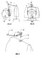
figure 1 is a perspective view of two different embodiments of the suspended main body depending on whether one or two zones of attachment respectively are provided with the suspension element; -
figure 2A is a perspective view of the preferred embodiment when the securing element is integrated into the actual vehicle; -
figure 2B is a lateral view showing the safety displacement upwards made by the device when the head is not supported on it; -
figures 3A and 3B are side and front views, respectively, in which the zone of the space where the main body of the invention hangs, along with its functioning axis and the axis of rotation of the neck, are indicated; -
figure 4 is a perspective view in which a securing element located in the upper zone of a headrest can be seen along with an embodiment of the removable suspension element prior to being positioned; -
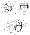
figures 5A and 5B are perspective views of two different embodiments in the case in which neither the securing element nor that for the suspension are previously integrated into the vehicle seat; -
figure 6 is a perspective view in cross-section of a suspension element integrated into the vehicle seat; -
figure 7 is a perspective view of another suspension element located above the head, generally in a permanent way, in the vehicle seat; -
figures 8A and 8B are perspective and front views, respectively, of an o embodiment with two securing zones located on both sides of the top part of the back-rest or headrest, without the use of rigid elements in its arrangement; -
figure 8C is a perspective view of an embodiment with two securing zones located on both sides of the top part of the back-rest or headrest, in which rigid elements are incorporated into its arrangement. - This type of vehicle has to have a securing element integrated into the design of the seat at the moment it is manufactured, though so far there is no record of any vehicle with this arrangement.
- Represented in
figure 1 are two different embodiments, non-limiting, of the suspended main body (MB). This concerns a lightweight element, resistant to traction, flexible and with a soft surface which in general comprises five differentiated zones depending on its use: the upper or suspension zone (1), with a design that permits adjustment so that it can be adapted to passengers of different heights; the lower or support zone (2), which is where the passenger will rest his or her head with its lower occipital part; the vertical lateral zones (3) which serve to restrict the sideways movements of the head and are generally located behind the ears; the front zone or frontal restraint element (4), which surrounds the frontal zone, thereby completing the restraint of the head, having a controlled breakage point depending on its composition, and being removable and adjustable to the contour of the forehead; finally, the intermediate or bridge zone (5), which connects the upper zone with the vertical lateral zones and which is the most rigid part of the suspended main body, leaving a space beneath which is occupied by the head of the passenger. - Although the external surface of the suspended main body is slightly soft and non-traumatic, it can contain inside itself a metallic structure which increases the resistance of the device and which acts as an element permitting a molding, preferably of the frontal restraint element, thereby improving its adaptation to the contour of the forehead and, in general, to the head.
-
Figure 2A shows that the hanging main body is suspended from a single rigid suspension element (6) which, in the form of a support bar, extends to a zone of the space located above the head of the seated passenger. The suspension element presents a design which fits with the securing element (7) located in the upper zone of the seat.Figure 2B shows that, in order to increase the safety of the device, the suspension element can incorporate a spring or tensioner (8) which causes the support bar to be displaced upwards whenever the head of the passenger is not resting in the suspended main body. -
Figures 3A and 3B show the zone of the space where the main body of the invention hangs. In the side-on view this zone is not separated (D) by more than 50 cm from the vertical projection of the front edge of the back-rest of the seat, and in the front-on view it is located in a way that is centered with respect to the seat and, therefore, with respect to the passenger's head. The main body of the invention is usually located hanging from the distal part of the suspension element (6). In the front-on view, the functioning axis (A-A') coincides with that of the neck (B-B') while in the side-on view the two are located close together in order to guarantee a better integral rotation of the head with the suspended device when the invention is used. -
Figure 4 shows that the securing element (7) is located in the upper and central part of the back-rest or of the headrest. This concerns an element fixed to the metallic structure of the seat and which comprises an opening in its upper zone, preferably square, rectangular or round in shape, which is where the distal end (9) of the suspension element is housed by means of a vertical coupling that can be released permitting said element to become detached from the seat, as a safety measure, due to the simple effect of gravity in the event of the vehicle toppling over, constituting what has been known as the "anti-topple safety design". In order to modify its length, the suspension element can comprise a telescopic extension mechanism (10) in its intermediate zone. - This type of vehicle can be any of those currently used for passenger transport.
- In
figure 5A , an embodiment that includes the entire securing system of the invention can be seen. This system comprises a rigid element (11) which is fixed in the vertical bars (12) of the vehicle headrest, and which in this embodiment has the form of an "H" so that it adapts better to the majority of headrests existing in automobiles. The securing is completed by means of screws or other similar elements (13), A support bar (14) is fixed in the securing element (11), generally via its rear part, in order to then follow an ascending path behind the headrest until reaching its upper edge (15). From this place, it will be directed by means of a suspension element (6), fixed or removable, towards the zone of the space, which has already been described in this document, located above the passenger's head. - Represented in
figure 5B is a suspension element (6), with a removable securing system which is fastened on the upper or rear surface of the actual back-rest or of the headrest of the vehicle and which can be adapted to any type of seat. It is based on the use of one or several cords, belts or similar elements (16), which are located in the horizontal or vertical direction and which directly secure the suspension element to the upper zone of the vehicle seat or to its headrest. Generally, this embodiment also comprises a securing plate (17) in order to improve its stability. - In this embodiment, a suspension bar (18) is integrated into the structure of the back-rest and remains hidden inside it when is not been used. When the invention is going to be used, the bar is manually pulled upwards. The cross-section represented in
figure 6 shows that, once outside of the seat and without becoming detached from it, the bar (18) is inclined forwards by means of a mechanism articulated in its base. The main body of the headrest is then hung. This bar can comprise an automatic withdrawal system, which acts when the head ceases to rest in the device by means of a spring, counterweight or similar element (19), located inside an internal cavity (20) of the seat, which is where said suspension bar is stored when it is not being used. -
Figure 7 shows a suspension element (21), which is located above the head, generally on a permanent basis, and which is adjustable in height from its securing zone (22) to the seat. The main body (MB) in which the head of the passenger rests hangs from the suspension element. -
Figures 8A and 8B show how the suspended main body (MB2) consists of a forward or frontal restraint zone (23), a lower or support zone (24), two vertical lateral zones (25) and two upper or suspension zones (26) which have various points of adjustment or a system, preferably of the hooks and loops kind, which permits adjustment for passengers of different heights. In this case the securing element (27) also acts as the suspension element and preferably consists of belts and cords which are fixed on both sides of the actual structure of the back-rest or of the headrest of the seat and which are adjusted to it preferably by means of a system of buckles or of hooks and loops (28). As shown infigure 8C , in cases in which the suspension element does not project sufficiently for guaranteeing correct functioning, this embodiment can be completed with the inclusion of a small lightweight suspension bar (29) attached to each side of the securing element (27) in order to extend forwards the point from where the main body hangs. As a means of protection for the head, this attachment is carried out in a way that is not fixed but is instead flexible and maintaining a certain degree of mobility so that no injury is caused in the event of an accident.
Claims (13)
- Suspended vertical head restraint for vehicle seats, which comprises a removable main body (MB) and a single rigid suspension element (6), the device being characterized in that:a) said removable main body (MB) is hanging from said single suspension element (6), it has mobility in all directions and has no direct contact with the seat, solely with said suspension element by means of a contact zone in which it is articulated, said main body having a construction that is light, flexible, resistant to traction and with a soft surface, with a design that allows for adaptation, according to the height, of different passengers and said main body (MB) generally comprising five zones according to its utility: an upper zone (1), which serves for hanging said body from the suspension element; a lower zone (2), which serves for supporting the head via its lower occipital part and restricting its displacement downward and backward; two vertical lateral zones (3) which serve for restricting the sideways movements of the head; a forward zone (4), which is adjustable and can be removed, and which serves for surrounding the frontal zone of the passenger, restricting the forward displacement of the head; and the bridge (5), which is the most rigid part of the suspended body and which leaves a space underneath where the head of the passenger is located, the functioning axis (A-A') having a component that is mainly vertical in order to allow for the integral rotation of the neck with the device during its use and having a slight inclination backwards, said axis passing mostly behind the ears.b) said single rigid suspension element (6), in the form of a support bar, which can be removable or be fixed in the vehicle, has a first end secured in the upper zone of the back-rest or of the headrest of the seat, and a second end which adopts a forward trajectory reaching as far as a zone of the space located at all times above the head of the seated passenger, said second end in its side-on view not presenting any separation (D) of more than 50 cm from the vertical projection of the front edge of the back-rest of the seat, and in the front-on view it is located in a way that is centered with respect to the seat and with respect to the head of the passenger, the main body being able to hang from any zone of the suspension element (6), generally from its front part said suspension element incorporates safety means (8) which cause the support bar to be displaced upwards as a safety measure when the head is not resting in the suspended main body (MB).
- Suspended vertical head restraint for vehicle seats, according to claim 1, characterized in that the safety means of the suspension element (6) are a spring or a tensioner (8).
- Suspended vertical head restraint for vehicle seats, according to claim 1, characterized in that the lower zone (2) of the suspended main body (MB) has the form of a net or comprises an array of holes in order to reduce as far as possible the contact area between the device and the head of the passenger.
- Suspended vertical head restraint for vehicle seats, according to claim 1, characterized in that parts of the suspended main body (MB) contain an internal metallic structure which has been over-molded or lined with a soft surface polymer, of an elastomer, silicone or similar type.
- Suspended vertical head restraint for vehicle seats, according to claim 1, characterized in that the suspension element (6) is removable and in its end closest (9) to the seat of the vehicle it comprises a section that fits with the securing element fixed to the metallic structure of the seat and located in its highest zone (7), generally via an opening located in its upper part.
- Suspended vertical head restraint for vehicle seats, according to claim 5, characterized in that the zone of attachment of the end closest to the seat (9) of the suspension element (6) with the securing element of the seat (7) has an anti-topple safety design by which the suspension element becomes detached from the seat due to the simple effect of gravity in the event of the vehicle toppling over.
- Suspended vertical head restraint for vehicle seats, according to claim 1, characterized in that the suspension element (6) is a metal bar which has a telescopic element (10) for adjusting the length of said bar.
- Suspended vertical head restraint for vehicle seats, according to claim 1, the vehicle being of the kind that comprises an individualized headrest on the back-rest, characterized in that both the suspension element (6) and the securing element (11) are removable, the securing element (11) being fixed to both vertical metal bars (12) of the headrest via its rear part, from which projects a support bar (14) which rises behind the headrest until it exceeds the height thereof, from which place it goes as far as the zone described above the head of the passenger from where the main body hangs.
- Suspended vertical head restraint for vehicle seats, according to claim 1, characterized in that suspension element (6) is secured in the upper part of the seat of the vehicle by means of one or several adjustable cords or belts (16), in such a way that it is easily removable, said suspension element (6) generally being supported on the upper part of the seat in order thereby to have greater stability and greater resistance and said element being able to be coupled to a securing plate (17) for this same purpose.
- Suspended vertical head restraint for vehicle seats, according to claim 1, characterized in that both the suspension element (18) and the securing element are integrated into the back-rest in a free space (20) located inside of it and in which is housed the actual suspension element (18) which can be extracted by manual vertical pulling so that it is finally located forwards by means of a mechanism articulated on its base, and which generally contains a counterweight, spring or similar (19) which exerts traction downwards on the suspension element in order to facilitate an automatic withdrawal of the same when the device is not being used.
- Suspended vertical head restraint for vehicle seats, according to claim 1, characterized in that the securing element (22) is integrated into the back-rest of the seat, the suspension element (21) being adjustable in height and at all times remaining above the head of the seated passenger.
- Suspended vertical head restraint for vehicle seats, which comprises a removable main body (MB2) and a securing and suspension element (27), also removable, the device being characterized in that:a) said removable main body (MB2) is hanging and attached to a securing and suspension element in two zones, it has mobility in all directions and has no direct contact with the seat, solely with said securing element, said main body having a construction that is light, flexible, resistant to traction and with a soft surface, with a design that allows for adaptation, according to the height, of different passengers and said main body generally comprising four zones according to its utility: two upper zones (26), which serve for hanging said body from the securing element; a lower zone (24), which serves for supporting the head via its lower occipital part and restricting its displacement downward and backward; two vertical lateral zones (25) which serve for restricting the sideways movements of the head; and a forward zone (23), which is adjustable and can be removed, and which serves for surrounding the frontal zone of the passenger, restricting the forward displacement of the head.b) said removable securing and suspension element (27) contains cords or belts which are adapted to both sides of the highest zone of the back-rest or ot the headrest of the seat, having a zone on each side of the head of the passenger, generally above the level of his or her eyes, from where the main body hangs.
- Suspended vertical head restraint for vehicle seats, according to claim 12, characterized in that a rigid bar (29) is secured in the belts or cords on each side of the head, being then directed in a forward direction as far as a point of the space located in its side-on view at less than 30 cm from the front edge of the back-rest of the seat and from where the main body (MB2) hangs, in which said securing is not fixed but instead flexible, and maintains a certain degree of mobility as a safety measure in the event of accident in order to prevent the rigid bar from being able to be traumatic for the head of the passenger.
Applications Claiming Priority (2)
| Application Number | Priority Date | Filing Date | Title |
|---|---|---|---|
| ES2008000160 | 2008-03-24 | ||
| PCT/ES2009/000097 WO2009118432A1 (en) | 2008-03-24 | 2009-02-23 | Suspended vertical head restraint for vehicle seats |
Publications (3)
| Publication Number | Publication Date |
|---|---|
| EP2255995A1 true EP2255995A1 (en) | 2010-12-01 |
| EP2255995A4 EP2255995A4 (en) | 2011-03-23 |
| EP2255995B1 EP2255995B1 (en) | 2011-12-28 |
Family
ID=41113001
Family Applications (1)
| Application Number | Title | Priority Date | Filing Date |
|---|---|---|---|
| EP09724413A Not-in-force EP2255995B1 (en) | 2008-03-24 | 2009-02-23 | Suspended vertical head restraint for vehicle seats |
Country Status (5)
| Country | Link |
|---|---|
| US (1) | US8172328B2 (en) |
| EP (1) | EP2255995B1 (en) |
| AT (1) | ATE538969T1 (en) |
| ES (1) | ES2376973T4 (en) |
| WO (1) | WO2009118432A1 (en) |
Families Citing this family (14)
| Publication number | Priority date | Publication date | Assignee | Title |
|---|---|---|---|---|
| US20110169316A1 (en) * | 2010-01-11 | 2011-07-14 | Marques Paul Goei | Portable Travel Headrest |
| CN101999807A (en) * | 2010-09-01 | 2011-04-06 | 杨俊琪 | Sleeping seat |
| DE102011015348B4 (en) * | 2011-03-28 | 2015-07-16 | Grammer Aktiengesellschaft | vehicle seat |
| US8646842B2 (en) * | 2011-06-20 | 2014-02-11 | Linda Barfuss | Salon chair having positionable support |
| US8528978B2 (en) | 2011-11-02 | 2013-09-10 | The Boeing Company | Transport vehicle seat back with integrated upright sleep support system |
| CN102755022A (en) * | 2012-07-15 | 2012-10-31 | 徐秉朗 | Computer chair capable of preventing cervical spondylosis |
| ES2485541B1 (en) | 2013-01-11 | 2015-10-15 | Siesta Systems S.L. | Radial tension distributor for vertical head restraint devices without mandibular support |
| EP3035825B1 (en) | 2013-08-22 | 2017-09-27 | The Boeing Company | Transport vehicle upright sleep support system |
| ES2429267B1 (en) * | 2013-09-20 | 2014-06-20 | Onlywise - Unipessoal Lda. | Head clamping device |
| US9241528B2 (en) * | 2014-03-03 | 2016-01-26 | Loren George Partlo | Sport safety headgear with bracing system and warning system |
| GB2528256A (en) * | 2014-07-14 | 2016-01-20 | Aqeel Javed | Sleep E'zzz |
| AU2016219062B2 (en) * | 2015-02-12 | 2018-03-01 | Jonathan Cook | Head and neck support and restraint system |
| US10172468B2 (en) | 2016-06-14 | 2019-01-08 | Glenn Scott Houghson | Adjustable portable headrest |
| CN109700262A (en) * | 2019-01-18 | 2019-05-03 | 王萍 | The vehicle-mounted back pillow adopting on head easy to support |
Citations (3)
| Publication number | Priority date | Publication date | Assignee | Title |
|---|---|---|---|---|
| US2828735A (en) * | 1956-06-19 | 1958-04-01 | Belton S Thompson | Traction device |
| DE9410151U1 (en) * | 1994-06-23 | 1995-03-02 | Knefel Georg Dipl Ing Maschine | Seat belt for the head when driving a car |
| DE4416780A1 (en) * | 1994-05-09 | 1995-11-16 | Ulf Stepanek | Safety arrangement for stabilising racing driver's helmet |
Family Cites Families (14)
| Publication number | Priority date | Publication date | Assignee | Title |
|---|---|---|---|---|
| US1837406A (en) * | 1929-10-18 | 1931-12-22 | Susie S Campbell | Head rest |
| US3645556A (en) * | 1968-12-18 | 1972-02-29 | Gic Kk | Safety net pillow for vehicle passengers |
| DE2529256B1 (en) | 1975-07-01 | 1976-12-16 | Roland Satzinger | SAFETY DEVICE FOR THE HEAD OF VEHICLE OCCUPANTS |
| US4339151A (en) * | 1980-01-14 | 1982-07-13 | Riggs Eric D | Head restraint |
| US4707031A (en) * | 1984-04-30 | 1987-11-17 | Meistrell Robert F | Head restraint |
| US4869240A (en) * | 1986-10-23 | 1989-09-26 | Boren John P | Cervical traction unit |
| DE3841024C1 (en) * | 1988-12-06 | 1989-10-05 | Siegfried 3012 Langenhagen De Maisenhaelder | |
| BR8902279A (en) * | 1989-05-16 | 1990-11-20 | Mara Teixeira De Freitas | SUPPORT AND SUPPORT DEVICE FOR HEADS |
| DE9001789U1 (en) | 1990-02-15 | 1990-04-19 | Handeck, Claus G., 4010 Hilden, De | |
| US5314404A (en) * | 1991-10-29 | 1994-05-24 | Biomechanical Design, Inc. | Tethered medical restraint device |
| US5511854A (en) * | 1993-07-01 | 1996-04-30 | Cordia; James M. | Head support and feeding aid |
| US6811222B1 (en) * | 2002-06-10 | 2004-11-02 | Cynthia K. Sumner | Chin and neck brace |
| DE102005045025B4 (en) | 2005-09-12 | 2007-11-29 | Schmücker, Hartmut, Dr. | Head-single-point and head-two-point safety belt system |
| US7393057B2 (en) * | 2006-05-26 | 2008-07-01 | Lorraine Fraser | Portable adjustable headrest |
-
2009
- 2009-02-23 WO PCT/ES2009/000097 patent/WO2009118432A1/en active Application Filing
- 2009-02-23 AT AT09724413T patent/ATE538969T1/en active
- 2009-02-23 EP EP09724413A patent/EP2255995B1/en not_active Not-in-force
- 2009-02-23 ES ES09724413T patent/ES2376973T4/en active Active
- 2009-02-23 US US12/601,358 patent/US8172328B2/en not_active Expired - Fee Related
Patent Citations (3)
| Publication number | Priority date | Publication date | Assignee | Title |
|---|---|---|---|---|
| US2828735A (en) * | 1956-06-19 | 1958-04-01 | Belton S Thompson | Traction device |
| DE4416780A1 (en) * | 1994-05-09 | 1995-11-16 | Ulf Stepanek | Safety arrangement for stabilising racing driver's helmet |
| DE9410151U1 (en) * | 1994-06-23 | 1995-03-02 | Knefel Georg Dipl Ing Maschine | Seat belt for the head when driving a car |
Non-Patent Citations (1)
| Title |
|---|
| See also references of WO2009118432A1 * |
Also Published As
| Publication number | Publication date |
|---|---|
| EP2255995A4 (en) | 2011-03-23 |
| WO2009118432A1 (en) | 2009-10-01 |
| US20100171353A1 (en) | 2010-07-08 |
| ATE538969T1 (en) | 2012-01-15 |
| ES2376973T4 (en) | 2013-11-26 |
| EP2255995B1 (en) | 2011-12-28 |
| US8172328B2 (en) | 2012-05-08 |
| ES2376973T3 (en) | 2012-03-21 |
Similar Documents
| Publication | Publication Date | Title |
|---|---|---|
| EP2255995B1 (en) | Suspended vertical head restraint for vehicle seats | |
| US8033603B2 (en) | Vehicle seat neck protection device | |
| US9566885B2 (en) | Head restraint | |
| US9572718B2 (en) | Eye mask | |
| US20050173962A1 (en) | Travel pillow | |
| US20100301655A1 (en) | Portable centering head cushion | |
| US6860563B1 (en) | Device for preventing or reducing tipping of the head | |
| CN105263366A (en) | Head restraint and seat for enhancing travel comfort | |
| CN204586562U (en) | A kind of safety comfortable type automotive seat | |
| US20170361747A1 (en) | Portable lumbar support apparatus | |
| US9364369B2 (en) | Head and neck support apparatus | |
| CN204547857U (en) | A kind of safety comfortable type automotive seat based on polyurethane buffering material | |
| US10576861B1 (en) | Whiplash injuries prevention headrest apparatus and drowsy driving prevention alarm | |
| CN112788966B (en) | Head stabilizer | |
| CN203388608U (en) | Portable headrest | |
| KR20110110545A (en) | Supplementary car headrest | |
| CN110562107A (en) | Multifunctional deformable automobile headrest | |
| KR200324056Y1 (en) | Car headrest | |
| RU2716301C1 (en) | I-fiks.safesleep pillow for child's head support during sleep in car seat | |
| JP3114505U (en) | Backrest seat with support | |
| JPWO2005009782A1 (en) | Whiplash prevention headrest | |
| KR20120000666U (en) | Cushion for car | |
| KR200330595Y1 (en) | Support Head Rest | |
| FI20195192A1 (en) | A head restraint | |
| KR19990005713U (en) | Headrest of seat |
Legal Events
| Date | Code | Title | Description |
|---|---|---|---|
| PUAI | Public reference made under article 153(3) epc to a published international application that has entered the european phase |
Free format text: ORIGINAL CODE: 0009012 |
|
| 17P | Request for examination filed |
Effective date: 20091023 |
|
| AK | Designated contracting states |
Kind code of ref document: A1 Designated state(s): AT BE BG CH CY CZ DE DK EE ES FI FR GB GR HR HU IE IS IT LI LT LU LV MC MK MT NL NO PL PT RO SE SI SK TR |
|
| AX | Request for extension of the european patent |
Extension state: AL BA RS |
|
| A4 | Supplementary search report drawn up and despatched |
Effective date: 20110218 |
|
| DAX | Request for extension of the european patent (deleted) | ||
| 17Q | First examination report despatched |
Effective date: 20110614 |
|
| GRAP | Despatch of communication of intention to grant a patent |
Free format text: ORIGINAL CODE: EPIDOSNIGR1 |
|
| GRAS | Grant fee paid |
Free format text: ORIGINAL CODE: EPIDOSNIGR3 |
|
| GRAA | (expected) grant |
Free format text: ORIGINAL CODE: 0009210 |
|
| AK | Designated contracting states |
Kind code of ref document: B1 Designated state(s): AT BE BG CH CY CZ DE DK EE ES FI FR GB GR HR HU IE IS IT LI LT LU LV MC MK MT NL NO PL PT RO SE SI SK TR |
|
| REG | Reference to a national code |
Ref country code: GB Ref legal event code: FG4D |
|
| REG | Reference to a national code |
Ref country code: CH Ref legal event code: EP |
|
| REG | Reference to a national code |
Ref country code: AT Ref legal event code: REF Ref document number: 538969 Country of ref document: AT Kind code of ref document: T Effective date: 20120115 |
|
| REG | Reference to a national code |
Ref country code: IE Ref legal event code: FG4D |
|
| REG | Reference to a national code |
Ref country code: DE Ref legal event code: R096 Ref document number: 602009004395 Country of ref document: DE Effective date: 20120308 |
|
| REG | Reference to a national code |
Ref country code: NL Ref legal event code: T3 |
|
| REG | Reference to a national code |
Ref country code: ES Ref legal event code: FG2A Ref document number: 2376973 Country of ref document: ES Kind code of ref document: T3 Effective date: 20120321 |
|
| PG25 | Lapsed in a contracting state [announced via postgrant information from national office to epo] |
Ref country code: LT Free format text: LAPSE BECAUSE OF FAILURE TO SUBMIT A TRANSLATION OF THE DESCRIPTION OR TO PAY THE FEE WITHIN THE PRESCRIBED TIME-LIMIT Effective date: 20111228 Ref country code: NO Free format text: LAPSE BECAUSE OF FAILURE TO SUBMIT A TRANSLATION OF THE DESCRIPTION OR TO PAY THE FEE WITHIN THE PRESCRIBED TIME-LIMIT Effective date: 20120328 |
|
| LTIE | Lt: invalidation of european patent or patent extension |
Effective date: 20111228 |
|
| PG25 | Lapsed in a contracting state [announced via postgrant information from national office to epo] |
Ref country code: GR Free format text: LAPSE BECAUSE OF FAILURE TO SUBMIT A TRANSLATION OF THE DESCRIPTION OR TO PAY THE FEE WITHIN THE PRESCRIBED TIME-LIMIT Effective date: 20120329 Ref country code: SI Free format text: LAPSE BECAUSE OF FAILURE TO SUBMIT A TRANSLATION OF THE DESCRIPTION OR TO PAY THE FEE WITHIN THE PRESCRIBED TIME-LIMIT Effective date: 20111228 Ref country code: LV Free format text: LAPSE BECAUSE OF FAILURE TO SUBMIT A TRANSLATION OF THE DESCRIPTION OR TO PAY THE FEE WITHIN THE PRESCRIBED TIME-LIMIT Effective date: 20111228 Ref country code: SE Free format text: LAPSE BECAUSE OF FAILURE TO SUBMIT A TRANSLATION OF THE DESCRIPTION OR TO PAY THE FEE WITHIN THE PRESCRIBED TIME-LIMIT Effective date: 20111228 Ref country code: HR Free format text: LAPSE BECAUSE OF FAILURE TO SUBMIT A TRANSLATION OF THE DESCRIPTION OR TO PAY THE FEE WITHIN THE PRESCRIBED TIME-LIMIT Effective date: 20111228 |
|
| PG25 | Lapsed in a contracting state [announced via postgrant information from national office to epo] |
Ref country code: CY Free format text: LAPSE BECAUSE OF FAILURE TO SUBMIT A TRANSLATION OF THE DESCRIPTION OR TO PAY THE FEE WITHIN THE PRESCRIBED TIME-LIMIT Effective date: 20111228 Ref country code: BE Free format text: LAPSE BECAUSE OF FAILURE TO SUBMIT A TRANSLATION OF THE DESCRIPTION OR TO PAY THE FEE WITHIN THE PRESCRIBED TIME-LIMIT Effective date: 20111228 |
|
| PG25 | Lapsed in a contracting state [announced via postgrant information from national office to epo] |
Ref country code: IS Free format text: LAPSE BECAUSE OF FAILURE TO SUBMIT A TRANSLATION OF THE DESCRIPTION OR TO PAY THE FEE WITHIN THE PRESCRIBED TIME-LIMIT Effective date: 20120428 Ref country code: BG Free format text: LAPSE BECAUSE OF FAILURE TO SUBMIT A TRANSLATION OF THE DESCRIPTION OR TO PAY THE FEE WITHIN THE PRESCRIBED TIME-LIMIT Effective date: 20120328 Ref country code: SK Free format text: LAPSE BECAUSE OF FAILURE TO SUBMIT A TRANSLATION OF THE DESCRIPTION OR TO PAY THE FEE WITHIN THE PRESCRIBED TIME-LIMIT Effective date: 20111228 Ref country code: CZ Free format text: LAPSE BECAUSE OF FAILURE TO SUBMIT A TRANSLATION OF THE DESCRIPTION OR TO PAY THE FEE WITHIN THE PRESCRIBED TIME-LIMIT Effective date: 20111228 Ref country code: EE Free format text: LAPSE BECAUSE OF FAILURE TO SUBMIT A TRANSLATION OF THE DESCRIPTION OR TO PAY THE FEE WITHIN THE PRESCRIBED TIME-LIMIT Effective date: 20111228 |
|
| PG25 | Lapsed in a contracting state [announced via postgrant information from national office to epo] |
Ref country code: PT Free format text: LAPSE BECAUSE OF FAILURE TO SUBMIT A TRANSLATION OF THE DESCRIPTION OR TO PAY THE FEE WITHIN THE PRESCRIBED TIME-LIMIT Effective date: 20120430 Ref country code: PL Free format text: LAPSE BECAUSE OF FAILURE TO SUBMIT A TRANSLATION OF THE DESCRIPTION OR TO PAY THE FEE WITHIN THE PRESCRIBED TIME-LIMIT Effective date: 20111228 Ref country code: RO Free format text: LAPSE BECAUSE OF FAILURE TO SUBMIT A TRANSLATION OF THE DESCRIPTION OR TO PAY THE FEE WITHIN THE PRESCRIBED TIME-LIMIT Effective date: 20111228 |
|
| REG | Reference to a national code |
Ref country code: AT Ref legal event code: MK05 Ref document number: 538969 Country of ref document: AT Kind code of ref document: T Effective date: 20111228 |
|
| PG25 | Lapsed in a contracting state [announced via postgrant information from national office to epo] |
Ref country code: MC Free format text: LAPSE BECAUSE OF NON-PAYMENT OF DUE FEES Effective date: 20120229 |
|
| PG25 | Lapsed in a contracting state [announced via postgrant information from national office to epo] |
Ref country code: DK Free format text: LAPSE BECAUSE OF FAILURE TO SUBMIT A TRANSLATION OF THE DESCRIPTION OR TO PAY THE FEE WITHIN THE PRESCRIBED TIME-LIMIT Effective date: 20111228 |
|
| PLBE | No opposition filed within time limit |
Free format text: ORIGINAL CODE: 0009261 |
|
| STAA | Information on the status of an ep patent application or granted ep patent |
Free format text: STATUS: NO OPPOSITION FILED WITHIN TIME LIMIT |
|
| REG | Reference to a national code |
Ref country code: IE Ref legal event code: MM4A |
|
| 26N | No opposition filed |
Effective date: 20121001 |
|
| REG | Reference to a national code |
Ref country code: DE Ref legal event code: R097 Ref document number: 602009004395 Country of ref document: DE Effective date: 20121001 |
|
| PG25 | Lapsed in a contracting state [announced via postgrant information from national office to epo] |
Ref country code: AT Free format text: LAPSE BECAUSE OF FAILURE TO SUBMIT A TRANSLATION OF THE DESCRIPTION OR TO PAY THE FEE WITHIN THE PRESCRIBED TIME-LIMIT Effective date: 20111228 Ref country code: IE Free format text: LAPSE BECAUSE OF NON-PAYMENT OF DUE FEES Effective date: 20120223 |
|
| PG25 | Lapsed in a contracting state [announced via postgrant information from national office to epo] |
Ref country code: MK Free format text: LAPSE BECAUSE OF FAILURE TO SUBMIT A TRANSLATION OF THE DESCRIPTION OR TO PAY THE FEE WITHIN THE PRESCRIBED TIME-LIMIT Effective date: 20111228 |
|
| PGFP | Annual fee paid to national office [announced via postgrant information from national office to epo] |
Ref country code: NL Payment date: 20130227 Year of fee payment: 5 |
|
| PG25 | Lapsed in a contracting state [announced via postgrant information from national office to epo] |
Ref country code: FI Free format text: LAPSE BECAUSE OF FAILURE TO SUBMIT A TRANSLATION OF THE DESCRIPTION OR TO PAY THE FEE WITHIN THE PRESCRIBED TIME-LIMIT Effective date: 20111228 |
|
| PG25 | Lapsed in a contracting state [announced via postgrant information from national office to epo] |
Ref country code: MT Free format text: LAPSE BECAUSE OF FAILURE TO SUBMIT A TRANSLATION OF THE DESCRIPTION OR TO PAY THE FEE WITHIN THE PRESCRIBED TIME-LIMIT Effective date: 20111228 |
|
| REG | Reference to a national code |
Ref country code: CH Ref legal event code: PL |
|
| REG | Reference to a national code |
Ref country code: ES Ref legal event code: PC2A Owner name: SIESTA SYSTEMS S.L. Effective date: 20131017 |
|
| PG25 | Lapsed in a contracting state [announced via postgrant information from national office to epo] |
Ref country code: LI Free format text: LAPSE BECAUSE OF NON-PAYMENT OF DUE FEES Effective date: 20130228 Ref country code: CH Free format text: LAPSE BECAUSE OF NON-PAYMENT OF DUE FEES Effective date: 20130228 |
|
| PG25 | Lapsed in a contracting state [announced via postgrant information from national office to epo] |
Ref country code: TR Free format text: LAPSE BECAUSE OF FAILURE TO SUBMIT A TRANSLATION OF THE DESCRIPTION OR TO PAY THE FEE WITHIN THE PRESCRIBED TIME-LIMIT Effective date: 20111228 |
|
| PG25 | Lapsed in a contracting state [announced via postgrant information from national office to epo] |
Ref country code: LU Free format text: LAPSE BECAUSE OF NON-PAYMENT OF DUE FEES Effective date: 20120223 |
|
| PG25 | Lapsed in a contracting state [announced via postgrant information from national office to epo] |
Ref country code: HU Free format text: LAPSE BECAUSE OF FAILURE TO SUBMIT A TRANSLATION OF THE DESCRIPTION OR TO PAY THE FEE WITHIN THE PRESCRIBED TIME-LIMIT Effective date: 20090223 |
|
| REG | Reference to a national code |
Ref country code: NL Ref legal event code: V1 Effective date: 20140901 |
|
| PG25 | Lapsed in a contracting state [announced via postgrant information from national office to epo] |
Ref country code: NL Free format text: LAPSE BECAUSE OF NON-PAYMENT OF DUE FEES Effective date: 20140901 |
|
| PGFP | Annual fee paid to national office [announced via postgrant information from national office to epo] |
Ref country code: IT Payment date: 20150218 Year of fee payment: 7 |
|
| REG | Reference to a national code |
Ref country code: FR Ref legal event code: PLFP Year of fee payment: 8 |
|
| REG | Reference to a national code |
Ref country code: FR Ref legal event code: PLFP Year of fee payment: 9 |
|
| PG25 | Lapsed in a contracting state [announced via postgrant information from national office to epo] |
Ref country code: IT Free format text: LAPSE BECAUSE OF NON-PAYMENT OF DUE FEES Effective date: 20160223 |
|
| REG | Reference to a national code |
Ref country code: ES Ref legal event code: PC2A Owner name: TILVE INVERSIONES S.L. Effective date: 20171113 |
|
| REG | Reference to a national code |
Ref country code: DE Ref legal event code: R079 Ref document number: 602009004395 Country of ref document: DE Free format text: PREVIOUS MAIN CLASS: B60N0002480000 Ipc: B60N0002800000 |
|
| REG | Reference to a national code |
Ref country code: GB Ref legal event code: 732E Free format text: REGISTERED BETWEEN 20180104 AND 20180110 |
|
| REG | Reference to a national code |
Ref country code: FR Ref legal event code: PLFP Year of fee payment: 10 |
|
| REG | Reference to a national code |
Ref country code: DE Ref legal event code: R081 Ref document number: 602009004395 Country of ref document: DE Owner name: TILVE INVERSIONES S.L., ES Free format text: FORMER OWNER: SIESTA SYSTEMS, S.A., ELCANO, NAVARRA, ES |
|
| REG | Reference to a national code |
Ref country code: FR Ref legal event code: TP Owner name: TILVE INVERSIONES, S.L., ES Effective date: 20180313 |
|
| PGFP | Annual fee paid to national office [announced via postgrant information from national office to epo] |
Ref country code: DE Payment date: 20190219 Year of fee payment: 11 Ref country code: ES Payment date: 20190301 Year of fee payment: 11 Ref country code: FR Payment date: 20190130 Year of fee payment: 11 Ref country code: GB Payment date: 20190205 Year of fee payment: 11 |
|
| REG | Reference to a national code |
Ref country code: DE Ref legal event code: R119 Ref document number: 602009004395 Country of ref document: DE |
|
| GBPC | Gb: european patent ceased through non-payment of renewal fee |
Effective date: 20200223 |
|
| PG25 | Lapsed in a contracting state [announced via postgrant information from national office to epo] |
Ref country code: GB Free format text: LAPSE BECAUSE OF NON-PAYMENT OF DUE FEES Effective date: 20200223 Ref country code: DE Free format text: LAPSE BECAUSE OF NON-PAYMENT OF DUE FEES Effective date: 20200901 Ref country code: FR Free format text: LAPSE BECAUSE OF NON-PAYMENT OF DUE FEES Effective date: 20200229 |
|
| REG | Reference to a national code |
Ref country code: ES Ref legal event code: FD2A Effective date: 20210708 |
|
| PG25 | Lapsed in a contracting state [announced via postgrant information from national office to epo] |
Ref country code: ES Free format text: LAPSE BECAUSE OF NON-PAYMENT OF DUE FEES Effective date: 20200224 |