EP2258952A2 - Pneumatic positioner with Piezo-pneumatic valve unit - Google Patents
Pneumatic positioner with Piezo-pneumatic valve unit Download PDFInfo
- Publication number
- EP2258952A2 EP2258952A2 EP10005741A EP10005741A EP2258952A2 EP 2258952 A2 EP2258952 A2 EP 2258952A2 EP 10005741 A EP10005741 A EP 10005741A EP 10005741 A EP10005741 A EP 10005741A EP 2258952 A2 EP2258952 A2 EP 2258952A2
- Authority
- EP
- European Patent Office
- Prior art keywords
- valve
- positioner
- pneumatic
- valves
- housing
- Prior art date
- Legal status (The legal status is an assumption and is not a legal conclusion. Google has not performed a legal analysis and makes no representation as to the accuracy of the status listed.)
- Granted
Links
- 238000000034 method Methods 0.000 claims abstract description 6
- 239000012528 membrane Substances 0.000 claims description 5
- 239000002243 precursor Substances 0.000 claims description 4
- 238000013022 venting Methods 0.000 claims description 3
- 239000011796 hollow space material Substances 0.000 claims 1
- 230000006870 function Effects 0.000 description 30
- 230000008859 change Effects 0.000 description 7
- 238000011161 development Methods 0.000 description 5
- 230000018109 developmental process Effects 0.000 description 5
- 238000009434 installation Methods 0.000 description 3
- 238000010276 construction Methods 0.000 description 2
- 230000009471 action Effects 0.000 description 1
- 230000006978 adaptation Effects 0.000 description 1
- 238000006243 chemical reaction Methods 0.000 description 1
- 230000008878 coupling Effects 0.000 description 1
- 238000010168 coupling process Methods 0.000 description 1
- 238000005859 coupling reaction Methods 0.000 description 1
- 230000001419 dependent effect Effects 0.000 description 1
- 238000010586 diagram Methods 0.000 description 1
- 230000000694 effects Effects 0.000 description 1
- 238000005516 engineering process Methods 0.000 description 1
- 230000002427 irreversible effect Effects 0.000 description 1
- 238000004519 manufacturing process Methods 0.000 description 1
- 230000009467 reduction Effects 0.000 description 1
- 230000001105 regulatory effect Effects 0.000 description 1
- 230000004044 response Effects 0.000 description 1
- 238000007789 sealing Methods 0.000 description 1
- 230000006641 stabilisation Effects 0.000 description 1
- 238000011105 stabilization Methods 0.000 description 1
Images


Classifications
-
- F—MECHANICAL ENGINEERING; LIGHTING; HEATING; WEAPONS; BLASTING
- F15—FLUID-PRESSURE ACTUATORS; HYDRAULICS OR PNEUMATICS IN GENERAL
- F15B—SYSTEMS ACTING BY MEANS OF FLUIDS IN GENERAL; FLUID-PRESSURE ACTUATORS, e.g. SERVOMOTORS; DETAILS OF FLUID-PRESSURE SYSTEMS, NOT OTHERWISE PROVIDED FOR
- F15B13/00—Details of servomotor systems ; Valves for servomotor systems
- F15B13/02—Fluid distribution or supply devices characterised by their adaptation to the control of servomotors
- F15B13/04—Fluid distribution or supply devices characterised by their adaptation to the control of servomotors for use with a single servomotor
- F15B13/0401—Valve members; Fluid interconnections therefor
- F15B13/0405—Valve members; Fluid interconnections therefor for seat valves, i.e. poppet valves
-
- F—MECHANICAL ENGINEERING; LIGHTING; HEATING; WEAPONS; BLASTING
- F15—FLUID-PRESSURE ACTUATORS; HYDRAULICS OR PNEUMATICS IN GENERAL
- F15B—SYSTEMS ACTING BY MEANS OF FLUIDS IN GENERAL; FLUID-PRESSURE ACTUATORS, e.g. SERVOMOTORS; DETAILS OF FLUID-PRESSURE SYSTEMS, NOT OTHERWISE PROVIDED FOR
- F15B13/00—Details of servomotor systems ; Valves for servomotor systems
- F15B2013/002—Modular valves, i.e. consisting of an assembly of interchangeable components
- F15B2013/006—Modular components with multiple uses, e.g. kits for either normally-open or normally-closed valves, interchangeable or reprogrammable manifolds
Definitions
- the present invention relates to a piezopneumatic valve unit and a pneumatic positioner with a pneumatic working member and acting on this piezopneumatische valve unit, which comprises two pneumatically coupled piezopneumatische with each other, wherein the valve unit has a signal input for an electrical control signal and a connectable to a compressed gas supply supply input, a having at the pneumatic working member connected working output and a vent outlet for the working medium (eg air). Furthermore, the invention relates to a method for adjusting or modifying the fail-safe behavior of such a pneumatic positioner or such a piezopneumatic valve unit.
- Such positioners advantageously serve to displace or pivot an actuator connected to the working member to thereby provide e.g. to regulate a valve or damper position.
- Generic positioners are usually constructed so that the working member is moved in a failure of the electrical (auxiliary) energy in a selected end position, wherein the end position of the working member defined by the structurally predetermined fluidic connection of the valves and their structure is. Positioners with different fail-safe behavior are therefore characterized overall by a different structural design. This proves to be particularly complicated or problematic if in a product range more positioner of the type mentioned with different fail-safe behavior to be offered or if the fail-safe behavior of a particular positioner should be changed.
- the object of the present invention a positioner or a piezo-pneumatic valve unit of the type mentioned in such a way that he or she can be adapted in the simplest and most cost-effective manner to a special fail-safe behavior. Accordingly, the intention of the present invention is to provide a method which is as simple and cost-effective as possible for setting or modifying the fail-safe behavior of such a pneumatic positioner or such a piezopneumatic valve unit.
- valves each have a valve housing and a function-specific valve insert which can be inserted sealingly into a receiving cavity of the respective valve housing with a flow-through switching unit, the valve seat and the actuator interacting therewith being adjustable by means of an adjusting drive Valve body are provided on the switching unit of the valve core and wherein disposed in the valve housing flow channels open in the associated receiving cavity, that with identical valve housing by replacing the valve insert different functional characteristics of the valve in question can be realized.
- Two pneumatic positioner according to the invention with different fail-safe behavior thus differ exclusively in that at least one of the receiving cavities of the two valve housing of a positioner - opposite the respective receiving cavity of the other positioner - is equipped with a different function-specific valve insert, which by the inventive design the positioner is only possible.
- each valve insert has at least one - the valve seat and the valve body of the respective valve comprehensive or containing - switching unit, the flow connections are connected at the intended installation in a receiving cavity of the valve housing with opening into the receiving cavity flow channels of the valve housing.
- Different function-specific valve inserts are therefore advantageously characterized by a different interconnection of flow channels within the switching unit or a different arrangement or position of valve body and valve seat.
- each valve housing the flow channels opening therein and various function-specific valve inserts are adapted to one another in such a way that different function-specific valve inserts can be sealingly received in each receiving cavity to achieve a different functional characteristic of the respective valve.
- valve housings of both valves are preferably constructed identically insofar as a function-specific valve insert can equally be used in each of the two valve housings.
- the flow channels provided in the two valve housings therefore preferably open into the same place in a receiving cavity of identical construction for both valves.
- a positioner according to the invention can have two different function-specific valve inserts, each defining a different functional characteristic for the valve equipped therewith, which in a first installation configuration (valve insert A in valve I, valve insert B in valve II) define a first fail-safe behavior of the positioner, while in the second possible built-in configuration (valve insert B in valve I, valve insert A in valve II) define a second fail-safe behavior for the positioner, which differs from the first fail-safe behavior is different.
- the two installation configurations mentioned differ only by an exchange of the two function-specific valve inserts.
- valves involved which are realized in the context of the present invention by various valve inserts to be inserted into the housing, it is in a particularly advantageous manner to a first functional characteristic, in which the relevant valve automatically transferred in its closed position in the event of power failure is (eg by a biasing the valve body in the direction of the valve seat spring), and a second functional characteristic in which the relevant valve is automatically transferred in the event of power failure in its open position (eg by a valve body in its spaced from the valve seat opening position biasing spring) ,
- it is therefore particularly preferable to provide at least two different function-specific valve inserts which can equally be inserted into the receiving cavities of the valve housings of both valves and by the function-specifically adapted design of their valves Switching provide the above-mentioned functionality.
- the two piezopneumatic valves of a positioner according to the invention are actuated separately by means of suitable electrical control signals in a piezoelectric manner, whereby at the same time the most energy-efficient operation of the positioner is ensured.
- two different control signals for the two adjusting drives of the two piezopneumatic valves are calculated in a suitable and known manner from the electrical control signal arriving at the signal input of the positioner with the aid of a control or regulating electronics (for example a microcontroller) connected to a power supply.
- the (at least) two valves of a positioner according to the invention in the manner of a two-stage Valve formed in which serving as a precursor and piezoelectrically actuated pilot valve, which in turn is connected to a pressurized gas supply, acts as a (pneumatic) adjustment for the valve body of a downstream booster stage (BoosterVentil).
- BoosterVentil booster stage
- Pilot valve and booster valve may preferably be connected to the same, applied to the supply input of the positioner compressed gas supply, wherein the pilot valve is preferably preceded by a pressure limiter, so that any fluctuations in the pressure in the compressed gas supply no or significantly reduced influence on the control or drive function of the Have pilot valve.
- the valve insert inserted into the receiving cavity of the valve housing thus comprises the switching unit of the (booster) valve whose valve body is adjusted by the piezopneumatic pilot valve functioning as a preliminary stage.
- the pneumatic working member of a positioner according to the invention may be part of a "single-acting" system with a working chamber connected to the working outlet of the piezopneumatic valve unit.
- the working member is in this case preferably moved by means of a pressurization of the working chamber against the force of a spring.
- the valve unit according to the invention forms in this case a 3/3-way system and has for this purpose two pneumatically coupled valves.
- the adjustable by means of the valve unit working member is part of a "double-acting" system, in which act on the working member from two different sides two individually pressurizable working chambers for its adjustment.
- the valve unit of a positioner according to the invention in this case has two separate working outputs for each working chamber of the working member and that in such a case a total of four piezopneumatische valves are provided, of which two valves are pneumatically coupled together and assigned to a working output of the valve unit ,
- the valve unit forms here a 5/3-way system, which is provided according to the invention that each of the four valves - as previously explained - interchangeable in a receiving cavity of the respective valve housing sealingly usable function-specific valve core, whereby the functional characteristics of each of the four valves and thus the fail-safe behavior of the positioner in a particularly simple manner to the desired application of the positioner is adaptable.
- each valve and the switching unit of the associated valve core form a common, replaceable as a whole assembly.
- Various function-specific Valve inserts then include as an exchangeable assembly and the adjustment of the valve in question.
- each valve and the switching unit of the associated valve insert form separate modules, thereby to achieve a different functional characteristics of the valve in question, only the switching unit (with valve body and valve seat) of the valve, but not the adjustment of the valve in question must be replaced.
- the different valve inserts effecting the different functional characteristics of the respective valve differ only in the scope of the respective switching unit, whereby in particular the adjusting drive can also be of identical design for different function-specific valve inserts.
- the force acting on the valve body adjusting drive and the switching unit are gas technology decoupled by a means of a membrane separated from the switching unit pneumatic volume, whereby a decoupling of Verstellantriebs wh and switching unit side prevailing operating media and pressures is realized.
- a decoupling of Verstellantriebs wh and switching unit side prevailing operating media and pressures is realized.
- an additional (restoring) force to be exerted on the valve body which promotes an automatic stabilization of the positioner against short-term input, drive or output pressure fluctuations.
- the valve housing of the at least two valves provided in the context of the present invention may be formed by a common valve housing.
- the common valve housing in the form of a valve housing block having at least one housing cover, having at least two receiving cavities.
- the at least one housing cover preferably closes the receiving cavities provided in the valve housing block for the valve inserts, whereby after removal of the at least one housing cover or prior to its assembly there is a suitable access to the receiving cavity.
- valve associated with each receiving cavity each extends into both the valve housing block and in the lid, in which case can be provided in a further preferred manner that the valve associated adjustment - at least partially - is housed in the projecting into the lid portion of the respective receiving cavity.
- the working outlet of the valve unit communicates with a flow channel interconnecting the two receiving cavities, i. is fluidically connected to this.
- the present invention initially relates to a pneumatic positioner in the above-explained sense, it should be noted that the features necessary for realizing the inventive success manifest themselves-almost exclusively-in the described embodiment of the piezopneumatic valve unit. Therefore, it is justifiable, the present invention also to a configured in accordance with the aforementioned features piezopneumatic Obtain valve unit for a pneumatic positioner.
- a valve unit according to the invention comprises two pneumatically coupled piezopneumatic valves, wherein the valve unit has a signal input for an electrical control signal and a supply input connectable to a pressurized gas supply, a connectable to the pneumatic working member of the positioner working output and a vent outlet for the working medium.
- valve unit is further characterized in that the valves each have a valve housing and a sealing insertable in a receiving cavity of the respective valve housing function-specific valve insert having a flow-through switching unit, wherein the valve seat and cooperating therewith, adjustable by means of an adjustment valve body on the switching unit the valve insert are provided and wherein arranged in the valve housing flow channels open in such a way in the associated receiving cavity, that with identical valve housing by replacing the valve insert different functional characteristics of the valve in question can be realized.
- the present invention relates to the method described in claim 14 for adjusting or modifying the fail-safe behavior of a pneumatic positioner or a piezopneumatic valve unit according to the invention.
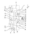
- the in Fig. 1 schematically represented pneumatic positioner 1 comprises a piezopneumatische valve unit 2 according to the invention, which acts on a pneumatic working member 3.
- a supply input 4 which can be connected to a pressurized gas supply
- a working output 5 connected to the working member 3
- a venting output 6 which is connected to the atmosphere or is suitably mounted, are provided.
- the presently designed as a single-acting system pneumatic working member 3 of the pneumatic positioner 1 comprises a displaceable within a cylinder 7 against the force of a spring 8 piston 9, which with e.g. a - not shown - flap or a valve can be operated.
- a spring 8 piston 9 which with e.g. a - not shown - flap or a valve can be operated.
- a - pneumatic working member 3 whose working chamber 10 is connected to the working output 5 of the piezoelectric valve unit 2.
- the piezopneumatic valve unit 2 further comprises two piezo-pneumatic valves 11, 12 which are pneumatically coupled together and connected to the working outlet 5 of the Valve unit 2 are connected.
- the valve 11 shown on the left serves by its connection to the supply input 4 of the valve unit 2 the pressure build-up in the working chamber 10 of the working member 3, while the valve 12 shown on the right serves by its interconnection with the vent outlet 6, the pressure reduction in the working chamber 10.
- Each of the two valves 11, 12 has exactly one function-specific valve insert 13, 14, wherein the valve inserts 13, 14 with respect to the function-specific design of their respective switching unit 15, 16 differ, as the Fig. 1 and 2 can be seen and will be explained in more detail below.
- the piezopneumatic valves 11, 12 each include a piezopneumatic precursor 19, 20 which functions as an adjusting drive 17, 18 and is designed identically for both valves 11, 12, with which the respective switching unit 15, 16 (or the valve body 21, 22; , Fig. 2 ) is actuated, as indicated by the dashed arrows 23, 24.
- Each piezopneumatic pilot valve 19, 20 is connected via a common pressure limiter 25 on the input side to the compressed gas supply applied to the supply input 4 of the valve unit 2 and is actuated via a piezoelectric element 27, 28, which in turn is connected to an electrical control circuit in the form of a programmable microcontroller 26 ,
- the microcontroller 26 is connected to the signal input 29 for an electrical control signal and an electrical power or voltage supply, not shown. It calculates suitable actuating signals for the two piezoelectric elements 27, 28 as a function of the control signal representing a setpoint value for the manipulated variable and the actual value of the manipulated variable.
- control variable for the illustrated positioner for example, the determinable at the working member 3 by means of a suitable sensor conventional type position of the piston 9 or determinable by a pressure sensor pressure in the working chamber 10 of the working member 3 and at the working output 5 of the valve unit. 2 serve.
- a sensor for this purpose which is not shown for the sake of better clarity, is preferably likewise connected to the microcontroller in order to calculate from the actual value of the manipulated variable determined by the sensor a suitable actuating signal for the adjusting drives 17, 18 of the two piezopneumatic valves 11, 12.
- Fig. 2 shows a section through the dashed lines indicated valve housing block 30 of the piezopneumatic valve unit 2 Fig. 1 ,
- the one-piece valve housing block 30 forms the two valve housings 31, 32 for receiving the valve inserts 13, 14 of the valves 11, 12.
- Each valve insert 13, 14 is sealingly received in an identical receiving cavity 33, 34.
- In the receiving cavities 33, 34 open flow channels 35, 36, 37 such that they are connected to the connections of corresponding flow channels of the switching units 15, 16 of the valve inserts 13, 14.
- the valves 11, 12 are pneumatically coupled via the flow channel 36, which simultaneously communicates with the working output 5 of the valve unit 2.
- Both linearly displaceable valve body 21, 22 of the valves 11, 12 are each by means of a - in Fig. 2 not shown - spring 38, 39 in the in Fig. 2 represented and biased the fail-safe state in case of failure of the electrical energy switching position and can by the (in Fig. 2 not shown and according to the arrows V1 and V2 indirectly acting on the valve body 21 and 22 respectively) piezopneumatische adjusting drive 17, 19, 23 and 18, 20, 24 counter to the respective spring force F spring are adjusted.
- the adjustment drives 17, 18 of both valves 11, 12 formed by the piezoelectric pilot valves 19, 20 are in this case coupled to the valve bodies in such a way that no force is exerted on the valve bodies 21 or 22 in the event of a failure of the electrical energy from them.
- valve body 21 of the valve insert 13 shown on the left by the spring force F spring against its valve seat 40 that is in a closed position, biased during the valve body 22 of the valve insert 14 shown on the right by the spring force F spring is biased in a spaced from its valve seat 41 opening position.
- NG normally closed
- NO normally open
- Positioner 1 shown overall means that in case of failure of the electrical energy of the working outlet 5 via the opening valve 12 connected to the vent outlet 6 and is decoupled by the closing valve 11 from the voltage applied to the supply input 4 compressed gas supply, whereby the working chamber 10 of the working member 3 is vented.
- the piston 9 of the working member 3 thus assumes under the action of the spring 8, the predetermined at unpressurized working chamber 10 end position.
- the working output 5 of the valve unit 2 is connected to the voltage applied to the supply input 4 compressed gas supply and decoupled from the vent outlet 6, whereby the pressure at the working output. 5 rises, so that the piston 9 of the working member 3 against the force of the spring 8 which compared to the embodiment of the Fig. 1 and 2 opposite end position of its maximum travel takes.
- Fig. 4 shows a section through the valve housing block 30 of another embodiment of the present invention, in turn, the positioner 1 and the valve unit 2 as such - with the exception of the valve inserts used for use 13 - are designed identically.
- FIG. 5 finally shows a section through the valve housing 31 of in Fig. 2
- the valve housing 31 includes a valve housing block 30 and a valve insert 13 covering the housing cover 42, in which a the entire Valve 11 (including pilot valve 19) receiving receiving cavity 33 is formed, wherein the adjusting drive 17 forming pilot valve 19 is completely housed in the projecting into the housing cover 42 portion of the receiving cavity 33.
- the double arrow P indicates the linear displaceability of the valve components connected to the valve 21.
- the pilot valve 19 acting as an adjusting drive 17 is decoupled from the switching unit 15 by a pneumatic volume 44 separated from the switching unit 15 of the valve core 13 by means of the membrane 43 and always vented.
- the membrane 43 is indirectly connected to the valve body 21 and exerts on this, as soon as it is displaced against the force F spring supported within the flow channel 35 spring 38, a restoring force F back to the valve body, which - as well as a the geometry of the booster valve resulting force F seat - the force F st of the pilot valve 19 is directed opposite.
- the equilibrium of forces that occurs at any given time has a self-stabilizing effect on the entire system against system fluctuations of all kinds.
- Valve insert in valve 12 (functional characteristics) Operating state pilot 20 13 (NG) out 14 (NO) out sinks out one no change one out undefined one one increases 14 (NO) out 13 (NG) out increases out one undefined one out no change one one sinks 13 (NG) out 13 (NG) out no change out one sinks one out increases one one undefined 14 (NO) out 14 (NO) out undefined out one increases one out sinks one one no change Functional characteristic of the valves Behavior of the outlet pressure in case of failure Valve 11 Valve 12 electrical power Compressed gas supply NG NO sinks sinks NO NG increases sinks NG NG no change sinks NO NO undefined sinks
- Table 3 shows the function characteristic-dependent fail-safe behavior of another positioner according to the invention, which is connected in a conventional manner to a double-acting working member and this four piezopneumatische valves A1, A2, B1, B2 of the type explained.
- the valves A1, B1 serve to control the pressure in a first working chamber of the working member connected to a first working outlet of the valve unit, while the valves A2, B2 serve to control the pressure in a second working chamber connected to a second working outlet of the valve unit.
Abstract
Description
Die vorliegender Erfindung betrifft eine piezopneumatische Ventileinheit sowie einen pneumatischen Stellungsregler mit einem pneumatischen Arbeitsglied und einer auf dieses wirkenden piezopneumatischen Ventileinheit, welche zwei miteinander pneumatisch gekoppelte piezopneumatische Ventile umfasst, wobei die Ventileinheit einen Signaleingang für ein elektrisches Steuersignal sowie einen an eine Druckgasversorgung anschließbaren Versorgungseingang, einen an das pneumatische Arbeitsglied angeschlossenen Arbeitsausgang und einen Entlüftungsausgang für das Arbeitsmedium (z.B. Luft) aufweist. Ferner betrifft die Erfindung ein Verfahren zur Einstellung bzw. Abänderung des Fail-Safe-Verhaltens eines solchen pneumatischen Stellungsreglers bzw. einer solchen piezopneumatischen Ventileinheit.The present invention relates to a piezopneumatic valve unit and a pneumatic positioner with a pneumatic working member and acting on this piezopneumatische valve unit, which comprises two pneumatically coupled piezopneumatische with each other, wherein the valve unit has a signal input for an electrical control signal and a connectable to a compressed gas supply supply input, a having at the pneumatic working member connected working output and a vent outlet for the working medium (eg air). Furthermore, the invention relates to a method for adjusting or modifying the fail-safe behavior of such a pneumatic positioner or such a piezopneumatic valve unit.
Solche Stellungsregler dienen in vorteilhafter Weise zur Verschiebung oder Verschwenkung eines mit dem Arbeitsglied verbundenen Stellglieds, um hierdurch z.B. eine Ventil- oder Klappenstellung zu regeln.Such positioners advantageously serve to displace or pivot an actuator connected to the working member to thereby provide e.g. to regulate a valve or damper position.
Gattungsgemäße Stellungsregler sind in der Regel so aufgebaut, dass das Arbeitsglied bei einem Ausfall der elektrischen (Hilfs-)Energie in eine ausgewählte Endlage verfahren wird, wobei die Endlage des Arbeitsglieds durch die konstruktiv vorgegebene strömungstechnische Verschaltung der Ventile und deren Aufbau definiert ist. Stellungsregler mit unterschiedlichem Fail-Safe-Verhalten sind daher insgesamt durch einen unterschiedlichen konstruktiven Aufbau gekennzeichnet. Dies erweist sich insbesondere dann als aufwendig bzw. problematisch, wenn in einem Produktsortiment mehrere Stellungsregler der eingangs genannten Art mit verschiedenem Fail-Safe-Verhalten angeboten werden sollen oder wenn das Fail-Safe-Verhalten eines bestimmten Stellungsreglers abgeändert werden soll.Generic positioners are usually constructed so that the working member is moved in a failure of the electrical (auxiliary) energy in a selected end position, wherein the end position of the working member defined by the structurally predetermined fluidic connection of the valves and their structure is. Positioners with different fail-safe behavior are therefore characterized overall by a different structural design. This proves to be particularly complicated or problematic if in a product range more positioner of the type mentioned with different fail-safe behavior to be offered or if the fail-safe behavior of a particular positioner should be changed.
Aus der
Ferner ist aus dem US-Patent
Vor diesem Hintergrund ist es die Aufgabe der vorliegenden Erfindung, einen Stellungsregler bzw. eine piezopneumatische Ventileinheit der eingangs genannten Art derart weiterzubilden, dass er bzw. sie auf möglichst einfache und kostengünstig Art und Weise an ein spezielles Fail-Safe-Verhalten anpassbar ist. Entsprechend soll mit der vorliegenden Erfindung ein auf möglichst einfache und kostengünstige Weise durchführbares Verfahren zur Einstellung bzw. Abänderung des Fail-Safe-Verhaltens eines solchen pneumatischen Stellungsreglers bzw. einer solchen piezopneumatischen Ventileinheit bereitgestellt werden.Against this background, it is the object of the present invention, a positioner or a piezo-pneumatic valve unit of the type mentioned in such a way that he or she can be adapted in the simplest and most cost-effective manner to a special fail-safe behavior. Accordingly, the intention of the present invention is to provide a method which is as simple and cost-effective as possible for setting or modifying the fail-safe behavior of such a pneumatic positioner or such a piezopneumatic valve unit.
Diese Aufgabe wird bei einem pneumatischen Stellungsregler der eingangs genannten Art durch die Merkmalskombination des Anspruchs 1 gelöst.This object is achieved in a pneumatic positioner of the type mentioned by the feature combination of
Dabei ist - neben den bereits eingangs genannten Merkmalen - erfindungsgemäß vorgesehen, dass die Ventile jeweils ein Ventilgehäuse und einen in einen Aufnahmehohlraum des betreffenden Ventilgehäuses dichtend einsetzbaren funktionsspezifischen Ventileinsatz mit einer durchströmten Schalteinheit aufweisen, wobei der Ventilsitz und der mit diesem zusammenwirkende, mittels eines Verstellantriebs verstellbare Ventilkörper an der Schalteinheit des Ventileinsatzes vorgesehen sind und wobei in dem Ventilgehäuse angeordnete Strömungskanäle dergestalt in den zugeordneten Aufnahmehohlraum münden, dass bei identischem Ventilgehäuse durch Austausch des Ventileinsatzes unterschiedliche Funktionscharakteristiken des betreffenden Ventils realisierbar sind.It is provided according to the invention - in addition to the features already mentioned - that the valves each have a valve housing and a function-specific valve insert which can be inserted sealingly into a receiving cavity of the respective valve housing with a flow-through switching unit, the valve seat and the actuator interacting therewith being adjustable by means of an adjusting drive Valve body are provided on the switching unit of the valve core and wherein disposed in the valve housing flow channels open in the associated receiving cavity, that with identical valve housing by replacing the valve insert different functional characteristics of the valve in question can be realized.
Im erfindungsgemäßen Sinne ist unter unterschiedlichen Funktionscharakteristiken also insbesondere ein unterschiedliches Fail-Safe-Verhalten des betreffenden Ventils, z.B. im Sinne eines vordefinierten Schaltzustands des Ventils, der sich bei Ausfall der elektrischen Energie oder bei Druckabfall am Versorgungseingang des Stellungsreglers einstellt, zu verstehen.In the sense of the invention, different functional characteristics therefore in particular a different fail-safe behavior of the valve in question, e.g. in the sense of a predefined switching state of the valve, which occurs at failure of the electrical energy or pressure drop at the supply input of the positioner to understand.
Zwei erfindungsgemäße pneumatische Stellungsregler mit verschiedenen Fail-Safe-Verhalten unterscheiden sich somit ausschließlich dadurch, dass wenigstens einer der Aufnahmehohlräume der beiden Ventilgehäuse des einen Stellungsreglers - gegenüber dem betreffenden Aufnahmehohlraum des anderen Stellungsreglers - mit einem unterschiedlichen funktionsspezifischen Ventileinsatz bestückt ist, was durch die erfindungsgemäße Ausgestaltung des Stellungsreglers erst ermöglicht wird.Two pneumatic positioner according to the invention with different fail-safe behavior thus differ exclusively in that at least one of the receiving cavities of the two valve housing of a positioner - opposite the respective receiving cavity of the other positioner - is equipped with a different function-specific valve insert, which by the inventive design the positioner is only possible.
Insoweit ist zur möglichst einfachen Erzielung des gewünschten Erfolges also von Bedeutung, dass die funktionsspezifischen Ventileinsätze derart in den Aufnahmehohlraum des betreffenden Ventils einsetzbar sind, dass sie jeweils durch einen anderen funktionsspezifischen Ventileinsatz austauschbar sind. Jeder Ventileinsatz weist dabei zumindest eine - den Ventilsitz und den Ventilkörper des jeweiligen Ventils umfassende bzw. beinhaltende - Schalteinheit auf, deren Strömungsanschlüsse bei bestimmungsgemäßer Montage in einem Aufnahmehohlraum des Ventilgehäuses mit in den Aufnahmehohlraum mündenden Strömungskanälen des Ventilgehäuses verbunden sind. Verschiedene funktionsspezifische Ventileinsätze sind daher vorteilhaft durch eine unterschiedliche Verschaltung von Strömungskanälen innerhalb der Schalteinheit bzw. eine unterschiedlichen Anordnung bzw. Lage von Ventilkörper und Ventilsitz gekennzeichnet. Ferner ist im Sinne der vorliegenden Erfindung vorgesehen, dass die von jedem Ventilgehäuse ausgebildeten Aufnahmehohlräume, die darin mündenden Strömungskanäle sowie verschiedene funktionsspezifische Ventileinsätze derart aneinander angepasst sind, dass zur Erzielung einer unterschiedlichen Funktionscharakteristik des betreffenden Ventils in jedem Aufnahmehohlraum verschiedene funktionsspezifische Ventileinsätze dichtend aufgenommen werden können.In that regard, for the simplest possible achievement of the desired success so important that the function-specific valve inserts are used in such a way in the receiving cavity of the valve in question that they are each interchangeable with another function-specific valve core. Each valve insert has at least one - the valve seat and the valve body of the respective valve comprehensive or containing - switching unit, the flow connections are connected at the intended installation in a receiving cavity of the valve housing with opening into the receiving cavity flow channels of the valve housing. Different function-specific valve inserts are therefore advantageously characterized by a different interconnection of flow channels within the switching unit or a different arrangement or position of valve body and valve seat. Further, in the context of the present invention, it is provided that the receiving cavities formed by each valve housing, the flow channels opening therein and various function-specific valve inserts are adapted to one another in such a way that different function-specific valve inserts can be sealingly received in each receiving cavity to achieve a different functional characteristic of the respective valve.
Die Ventilgehäuse beider Ventile sind zusammen mit den in ihren Aufnahmehohlraum mündenden Strömungskanälen bevorzugt insoweit identisch aufgebaut, dass ein funktionsspezifischer Ventileinsatz gleichermaßen in jedem der beiden Ventilgehäuse verwendbar ist. Die in beiden Ventilgehäusen vorgesehenen Strömungskanäle münden also bevorzugt jeweils an gleicher Stelle in einen für beide Ventile identisch ausgestalteten Aufnahmehohlraum. Durch bloßen Austausch eines ersten funktionsspezifischen Ventileinsatzes durch einen zweiten funktionsspezifischen Ventileinsatz (anderer Bauart bzw. Funktion) lässt sich damit die Funktionscharakteristik des betreffenden Ventils und hierüber im Ergebnis das Fail-Safe-Verhalten des gesamten Stellungsreglers auf einfache Weise einstellen bzw. abändern.The valve housings of both valves, together with the flow channels opening into their receiving cavity, are preferably constructed identically insofar as a function-specific valve insert can equally be used in each of the two valve housings. The flow channels provided in the two valve housings therefore preferably open into the same place in a receiving cavity of identical construction for both valves. By simply replacing a first function-specific valve insert by a second function-specific valve insert (other type or function) can thus adjust the function of the valve in question and this as a result, the fail-safe behavior of the entire positioner in a simple way or modify.
Vorteilhaft kann im Rahmen der vorliegenden Erfindung vorgesehen sein, dass ein erfindungsgemäßer Stellungsregler zwei verschiedene - je eine andere Funktionscharakteristik für das damit bestücktes Ventil definierende - funktionsspezifische Ventileinsätze aufweist, die in einer ersten Einbau-Konfiguration (Ventileinsatz A in Ventil I; Ventileinsatz B in Ventil II) ein erstes Fail-Safe-Verhalten des Stellungsreglers definieren, während sie in der zweiten möglichen Einbau-Konfiguration (Ventileinsatz B in Ventil I; Ventileinsatz A in Ventil II) ein zweites Fail-Safe-Verhalten für den Stellungsregler definieren, welches sich vom ersten Fail-Safe-Verhalten unterscheidet. Die beiden genannten Einbau-Konfigurationen unterscheiden sich dabei lediglich durch eine Vertauschung der beiden funktionsspezifischen Ventileinsätze.Advantageously, it can be provided within the scope of the present invention for a positioner according to the invention to have two different function-specific valve inserts, each defining a different functional characteristic for the valve equipped therewith, which in a first installation configuration (valve insert A in valve I, valve insert B in valve II) define a first fail-safe behavior of the positioner, while in the second possible built-in configuration (valve insert B in valve I, valve insert A in valve II) define a second fail-safe behavior for the positioner, which differs from the first fail-safe behavior is different. The two installation configurations mentioned differ only by an exchange of the two function-specific valve inserts.
Mit der vorliegenden Erfindung wird jedoch nicht nur die Umrüstung eines bestehenden Stellungsreglers im Hinblick auf ein geändertes Fail-Safe-Verhalten erleichtert, sondern es wird auch im Falle der Herstellung eines erfindungsgemäßen Stellungsreglers, also im Falle der Erstbestückung der betreffenden Aufnahmehohlräume mit funktionsspezifischen Ventileinsätzen, eine besonders einfache Anpassung des Stellungsreglers an den gewünschten Einsatzzweck erlaubt. Eine mit der vorliegenden Erfindung realisierbare Baureihe von Stellungsreglern mit verschiedenem Fail-Safe-Verhalten ist daher durch einen - mit Ausnahme der Ventileinsätze - identischen Aufbau aller Stellungsregler der Baureihe gekennzeichnet.With the present invention, however, not only the conversion of an existing positioner in terms of a modified fail-safe behavior is facilitated, but it is also in the case of the production of a positioner according to the invention, ie in Case of Erstbestückung the respective receiving cavities with function-specific valve inserts, a particularly simple adaptation of the positioner to the desired application allowed. A realizable with the present invention series of positioner with different fail-safe behavior is therefore characterized by a - with the exception of the valve inserts - identical structure of all positioners of the series.
Bei den verschiedenen Funktionscharakteristiken der beteiligten Ventile, die im Rahmen der vorliegenden Erfindung durch verschiedene in das Gehäuse einzusetzende Ventileinsätze realisiert werden, handelt es sich in besonders vorteilhafter Weise um eine erste Funktionscharakteristik, bei der das betreffende Ventil im Falle eines Energieausfalls selbsttätig in seine Schließstellung überführt wird (z.B. durch eine den Ventilkörper in Richtung des Ventilsitzes vorspannende Feder), und eine zweite Funktionscharakteristik, bei der das betreffende Ventil im Falle eines Energieausfalls selbsttätig in seine Öffnungsstellung überführt wird (z.B. durch eine den Ventilkörper in seine vom Ventilsitz beabstandete Öffnungsstellung vorspannende Feder). Es werden im Rahmen der vorliegenden Erfindung also besonders bevorzugt wenigstens zwei verschiedene funktionsspezifische Ventileinsätze bereitgestellt, die gleichermaßen in die Aufnahmehohlräume der Ventilgehäuse beider Ventile einsetzbar sind und durch die funktionsspezifisch angepasste Ausgestaltung ihrer Schalteinheit die vorstehend erwähnte Funktionalität bereitstellen.In the various functional characteristics of the valves involved, which are realized in the context of the present invention by various valve inserts to be inserted into the housing, it is in a particularly advantageous manner to a first functional characteristic, in which the relevant valve automatically transferred in its closed position in the event of power failure is (eg by a biasing the valve body in the direction of the valve seat spring), and a second functional characteristic in which the relevant valve is automatically transferred in the event of power failure in its open position (eg by a valve body in its spaced from the valve seat opening position biasing spring) , In the context of the present invention, it is therefore particularly preferable to provide at least two different function-specific valve inserts which can equally be inserted into the receiving cavities of the valve housings of both valves and by the function-specifically adapted design of their valves Switching provide the above-mentioned functionality.
Die zwei piezopneumatischen Ventile eines erfindungsgemäßen Stellungsreglers werden mittels geeigneter elektrischer Stellsignale auf piezoelektrische Weise separat betätigt, wodurch gleichzeitig ein möglichst energieeffizienter Betrieb des Stellungsreglers sichergestellt ist. Insoweit werden aus dem am Signaleingang des Stellungsreglers eingehenden elektrischen Steuersignal unter Zuhilfenahme einer an eine Energieversorgung angeschlossenen Steuer- bzw. Regelelektronik (z.B. eines Mikrocontrollers) auf geeignete und bekannte Weise zwei verschiedene Stellsignale für die beiden Verstellantriebe der beiden piezopneumatischen Ventile berechnet und entsprechend bereit gestellt.The two piezopneumatic valves of a positioner according to the invention are actuated separately by means of suitable electrical control signals in a piezoelectric manner, whereby at the same time the most energy-efficient operation of the positioner is ensured. To this extent, two different control signals for the two adjusting drives of the two piezopneumatic valves are calculated in a suitable and known manner from the electrical control signal arriving at the signal input of the positioner with the aid of a control or regulating electronics (for example a microcontroller) connected to a power supply.
Bezüglich des konkreten Aufbaus der piezopneumatischen Ventile sei auf die insoweit aus dem Stand der Technik bekannten Arten piezopneumatischer Ventile verwiesen, wobei im Rahmen der vorliegenden Erfindung in einer ersten bevorzugten Weiterbildung der Erfindung vorgesehen ist, dass der Verstellantrieb in Form einer piezopneumatischen Vorstufe, also in Form eines piezopneumatischen Pilotventils, welches mittelbar oder unmittelbar auf den Ventilkörper einer nachgeschalteten Ventilstufe einwirkt, ausgeführt ist.With regard to the concrete structure of the piezopneumatic valves reference is made to the extent known from the prior art types of piezo-pneumatic valves, being provided in the context of the present invention in a first preferred embodiment of the invention that the adjustment in the form of a piezopneumatic precursor, ie in shape a piezo-pneumatic pilot valve, which acts directly or indirectly on the valve body of a downstream valve stage, is executed.
Damit sind die (wenigstens) zwei Ventile eines erfindungsgemäßen Stellungsreglers in Art eines zweistufigen Ventils ausgebildet, bei dem das als Vorstufe dienende und piezoelektrisch betätigbare Pilotventil, welches seinerseits mit einer Druckgasversorgung verbunden ist, als (pneumatischer) Verstellantrieb für den Ventilkörper einer nachgeschalteten Booster-Stufe (BoosterVentil) fungiert.Thus, the (at least) two valves of a positioner according to the invention in the manner of a two-stage Valve formed in which serving as a precursor and piezoelectrically actuated pilot valve, which in turn is connected to a pressurized gas supply, acts as a (pneumatic) adjustment for the valve body of a downstream booster stage (BoosterVentil).
Pilotventil und Boosterventil können bevorzugt an die gleiche, am Versorgungseingang des Stellungsreglers anliegende Druckgasversorgung angeschlossen sein, wobei dem Pilotventil bevorzugt ein Druckbegrenzer vorgeschaltet ist, so dass etwaige Schwankungen des Drucks in der Druckgasversorgung keinen oder einen deutlich verminderten Einfluss auf die Stell- bzw. Antriebsfunktion des Pilotventils haben. Der in den Aufnahmehohlraum des Ventilgehäuses eingesetzte Ventileinsatz umfasst somit die Schalteinheit des (Booster-)Ventils, dessen Ventilkörper durch das als Vorstufe fungierende piezopneumatische Pilotventil verstellt wird.Pilot valve and booster valve may preferably be connected to the same, applied to the supply input of the positioner compressed gas supply, wherein the pilot valve is preferably preceded by a pressure limiter, so that any fluctuations in the pressure in the compressed gas supply no or significantly reduced influence on the control or drive function of the Have pilot valve. The valve insert inserted into the receiving cavity of the valve housing thus comprises the switching unit of the (booster) valve whose valve body is adjusted by the piezopneumatic pilot valve functioning as a preliminary stage.
Ferner sei darauf hingewiesen, dass das pneumatische Arbeitsglied eines erfindungsgemäßen Stellungsreglers Teil eines "einfach wirkenden" Systems mit einer - an den Arbeitsausgang der piezopneumatischen Ventileinheit angeschlossenen - Arbeitskammer sein kann. Das Arbeitglied wird hierbei bevorzugt mittels einer Druckbeaufschlagung der Arbeitskammer gegen die Kraft einer Feder verschoben. Die erfindungsgemäße Ventileinheit bildet in diesem Fall ein 3/3-Wegesystem und weist hierfür zwei pneumatisch gekoppelte Ventile auf.It should also be noted that the pneumatic working member of a positioner according to the invention may be part of a "single-acting" system with a working chamber connected to the working outlet of the piezopneumatic valve unit. The working member is in this case preferably moved by means of a pressurization of the working chamber against the force of a spring. The valve unit according to the invention forms in this case a 3/3-way system and has for this purpose two pneumatically coupled valves.
Gleichfalls kommt für die vorliegende Erfindung jedoch in Betracht, dass das mittels der Ventileinheit verstellbare Arbeitsglied Teil eines "doppelt wirkenden" Systems ist, bei welchem auf das Arbeitsglied von verschiedenen Seiten zwei individuell mit Druck beaufschlagbare Arbeitskammern zu dessen Verstellung einwirken. Es versteht sich, dass die Ventileinheit eines erfindungsgemäßen Stellungsreglers in diesem Fall zwei getrennte Arbeitsausgänge für jede Arbeitskammer des Arbeitsglieds aufweist und dass in einem solchen Fall insgesamt vier piezopneumatische Ventile vorzusehen sind, von denen jeweils zwei Ventile pneumatisch miteinander gekoppelt und einem Arbeitsausgang der Ventileinheit zugeordnet sind. Die Ventileinheit bildet hier ein 5/3-Wegesystem, wobei erfindungsgemäß vorgesehen ist, dass jedes der vier Ventile einen - wie bereits zuvor erläutert - austauschbar in einen Aufnahmehohlraum des jeweiligen Ventilgehäuses dichtend einsetzbaren funktionsspezifischen Ventileinsatz aufweist, wodurch die Funktionscharakteristik jedes der vier Ventile und damit das Fail-Safe-Verhalten des Stellungsreglers in besonders einfacher Weise an den gewünschten Einsatzzweck des Stellungsreglers anpassbar ist.Likewise, however, comes into consideration for the present invention, that the adjustable by means of the valve unit working member is part of a "double-acting" system, in which act on the working member from two different sides two individually pressurizable working chambers for its adjustment. It is understood that the valve unit of a positioner according to the invention in this case has two separate working outputs for each working chamber of the working member and that in such a case a total of four piezopneumatische valves are provided, of which two valves are pneumatically coupled together and assigned to a working output of the valve unit , The valve unit forms here a 5/3-way system, which is provided according to the invention that each of the four valves - as previously explained - interchangeable in a receiving cavity of the respective valve housing sealingly usable function-specific valve core, whereby the functional characteristics of each of the four valves and thus the fail-safe behavior of the positioner in a particularly simple manner to the desired application of the positioner is adaptable.
Im Rahmen der vorliegenden Erfindung kann in einer ersten Variante vorgesehen sein, dass der Verstellantrieb jedes Ventils und die Schalteinheit des zugehörigen Ventileinsatzes eine gemeinsame, als ganzes austauschbare Baugruppe bilden. Verschiedene funktionsspezifische Ventileinsätze umfassen dann als austauschbare Baugruppe auch den Verstellantrieb des betreffenden Ventils.In the context of the present invention may be provided in a first variant, that the adjustment of each valve and the switching unit of the associated valve core form a common, replaceable as a whole assembly. Various function-specific Valve inserts then include as an exchangeable assembly and the adjustment of the valve in question.
Alternativ hierzu kann in einer zweiten Variante der Erfindung vorgesehen sein, dass der Verstellantrieb jedes Ventils und die Schalteinheit des zugehörigen Ventileinsatzes getrennte Baugruppen bilden, wodurch zur Erzielung einer verschiedenen Funktionscharakteristik des betreffenden Ventils nur die Schalteinheit (mit Ventilkörper und Ventilsitz) des Ventils, nicht jedoch der Verstellantrieb des betreffenden Ventils ausgetauscht werden muss.Alternatively, it can be provided in a second variant of the invention that the adjustment of each valve and the switching unit of the associated valve insert form separate modules, thereby to achieve a different functional characteristics of the valve in question, only the switching unit (with valve body and valve seat) of the valve, but not the adjustment of the valve in question must be replaced.
Beide vorgenannten Varianten können sich - je nach der konkreten Ausgestaltung des Verstellantriebs und seiner Anbindung an den Ventilkörper - als vorteilhaft und einfacher zu realisieren erweisen.Both of the aforementioned variants can prove to be advantageous and easier to implement, depending on the specific embodiment of the adjusting drive and its connection to the valve body.
In einer bevorzugten Weiterbildung der vorliegenden Erfindung ist vorgesehen, dass die die unterschiedliche Funktionscharakteristiken des betreffenden Ventils bewirkenden verschiedenen Ventileinsätze sich nur im Umfang der jeweiligen Schalteinheit unterscheiden, wodurch insbesondere auch der Verstellantrieb zu verschiedenen funktionsspezifischen Ventileinsätzen baugleich ausgestaltet sein kann.In a preferred development of the present invention, it is provided that the different valve inserts effecting the different functional characteristics of the respective valve differ only in the scope of the respective switching unit, whereby in particular the adjusting drive can also be of identical design for different function-specific valve inserts.
Ferner ist im Rahmen einer abermals bevorzugten Weiterbildung der vorliegenden Erfindung vorgesehen, dass bei den Ventileinsätzen jeweils der auf den Ventilkörper einwirkende Verstellantrieb und die Schalteinheit gastechnisch durch ein mittels einer Membran von der Schalteinheit abgetrenntes pneumatisches Volumen entkoppelt sind, wodurch eine Entkopplung der verstellantriebsseitig und schalteinheitsseitig vorherrschenden Betriebsmedien und -drücke realisiert ist. Ferner kann mit einer solchen, bevorzugt mit dem Ventilkörper der Schalteinheit gekoppelten Membran eine zusätzliche (Rückstell-)Kraft auf den Ventilkörper ausgeübt werden, was eine selbsttätige Stabilisierung des Stellungsreglers gegenüber kurzfristigen eingangs-, antriebs- oder ausgangseitige Druckschwankungen befördert.Furthermore, it is provided in the context of a again preferred development of the present invention that at the valve inserts in each case the force acting on the valve body adjusting drive and the switching unit are gas technology decoupled by a means of a membrane separated from the switching unit pneumatic volume, whereby a decoupling of Verstellantriebsseitig and switching unit side prevailing operating media and pressures is realized. Further, with such, preferably coupled to the valve body of the switching unit membrane an additional (restoring) force to be exerted on the valve body, which promotes an automatic stabilization of the positioner against short-term input, drive or output pressure fluctuations.
In besonders bevorzugter Art und Weise können die im Rahmen der vorliegenden Erfindung vorgesehenen Ventilgehäuse der wenigstens zwei Ventile durch ein gemeinsames Ventilgehäuse gebildet sein. Dabei bietet es sich zur Erzielung einer besonders kompakten und robusten Bauweise insbesondere an, das gemeinsame Ventilgehäuse in Form eines - wenigstens zwei Aufnahmehohlräume aufweisenden - Ventilgehäuseblocks mit mindestens einem Gehäusedeckel auszubilden. Der wenigstens eine Gehäusedeckel verschließt bevorzugt die in dem Ventilgehäuseblock vorgesehenen Aufnahmehohlräume für die Ventileinsätze, wodurch nach Abnahme des wenigstens einen Gehäusedeckels bzw. vor dessen Montage ein geeigneter Zugang zu dem Aufnahmehohlraum besteht. Besonders bevorzugt kann hierbei in einer nochmaligen Weiterbildung der Erfindung vorgesehen sein, dass sich der jedem Ventil zugeordnete Aufnahmehohlraum jeweils sowohl in den Ventilgehäuseblock als auch in den Deckel hinein erstreckt, wobei dann in nochmals bevorzugter Weise vorgesehen sein kann, dass der einem Ventil zugeordnete Verstellantrieb - zumindest teilweise - in dem in den Deckel hineinragenden Bereich des betreffenden Aufnahmehohlraumes untergebracht ist. Durch Abnahme des Gehäusedeckels mitsamt dem darin untergebrachten Verstellantrieb wird somit der Aufnahmehohlraum zum Einsatz oder Austausch eines funktionsspezifischen Ventileinsatzes zugänglich.In a particularly preferred manner, the valve housing of the at least two valves provided in the context of the present invention may be formed by a common valve housing. In order to achieve a particularly compact and robust construction, it is particularly appropriate in particular to form the common valve housing in the form of a valve housing block having at least one housing cover, having at least two receiving cavities. The at least one housing cover preferably closes the receiving cavities provided in the valve housing block for the valve inserts, whereby after removal of the at least one housing cover or prior to its assembly there is a suitable access to the receiving cavity. Particularly preferred may be provided in a further development of the invention that the valve associated with each receiving cavity each extends into both the valve housing block and in the lid, in which case can be provided in a further preferred manner that the valve associated adjustment - at least partially - is housed in the projecting into the lid portion of the respective receiving cavity. By removing the housing cover together with the adjusting drive housed therein, the receiving cavity is thus accessible for use or replacement of a function-specific valve insert.
Bezüglich der pneumatischen Kopplung der beiden Ventile und der Verschaltung der Ventileinheit ist vorteilhaft vorgesehen, dass der Arbeitsausgang der Ventileinheit mit einem die beiden Aufnahmehohlräume miteinander verbindenden Strömungskanal kommuniziert, d.h. mit diesem strömungstechnisch verbunden ist.With regard to the pneumatic coupling of the two valves and the interconnection of the valve unit, it is advantageously provided that the working outlet of the valve unit communicates with a flow channel interconnecting the two receiving cavities, i. is fluidically connected to this.
Obgleich die vorliegende Erfindung im vorstehend erläuterten Sinne zunächst einen pneumatischen Stellungsregler betrifft, ist festzustellen, dass sich die zur Realisierung des erfindungsgemäßen Erfolgs notwendigen Merkmale - beinahe ausschließlich - in der beschriebenen Ausgestaltung der piezopneumatischen Ventileinheit manifestieren. Daher ist es gerechtfertigt, die vorliegende Erfindung auch auf eine in Übereinstimmung mit den vorgenannten Merkmalen ausgestaltete piezopneumatische Ventileinheit für einen pneumatischen Stellungsregler zu beziehen. Eine solche erfindungsgemäße Ventileinheit umfasst zwei miteinander pneumatisch gekoppelte piezopneumatische Ventile, wobei die Ventileinheit einen Signaleingang für ein elektrisches Steuersignal sowie einen an eine Druckgasversorgung anschließbaren Versorgungseingang, einen an das pneumatische Arbeitsglied des Stellungsreglers anschließbaren Arbeitsausgang und einen Entlüftungsausgang für das Arbeitsmedium aufweist. Die erfindungsgemäße Ventileinheit ist dabei ferner dadurch gekennzeichnet, dass die Ventile jeweils ein Ventilgehäuse und einen in einen Aufnahmehohlraum des betreffenden Ventilgehäuses dichtend einsetzbaren funktionsspezifischen Ventileinsatz mit einer durchströmten Schalteinheit aufweisen, wobei der Ventilsitz und der mit diesem zusammenwirkende, mittels eines Verstellantriebs verstellbare Ventilkörper an der Schalteinheit des Ventileinsatzes vorgesehen sind und wobei in dem Ventilgehäuse angeordnete Strömungskanäle dergestalt in den zugeordneten Aufnahmehohlraum münden, dass bei identischem Ventilgehäuse durch Austausch des Ventileinsatzes unterschiedliche Funktionscharakteristiken des betreffenden Ventils realisierbar sind. Ersichtlich gelten bezüglich der Vorteile einer solchen Ventileinheit wie auch bezüglich bevorzugter Weiterbildungen einer solchen Ventileinheit alle vorstehend genannten Aspekte in gleicher Weise, so dass insoweit zur Vermeidung von Wiederholungen auf die vorstehenden Ausführungen verwiesen sei.Although the present invention initially relates to a pneumatic positioner in the above-explained sense, it should be noted that the features necessary for realizing the inventive success manifest themselves-almost exclusively-in the described embodiment of the piezopneumatic valve unit. Therefore, it is justifiable, the present invention also to a configured in accordance with the aforementioned features piezopneumatic Obtain valve unit for a pneumatic positioner. Such a valve unit according to the invention comprises two pneumatically coupled piezopneumatic valves, wherein the valve unit has a signal input for an electrical control signal and a supply input connectable to a pressurized gas supply, a connectable to the pneumatic working member of the positioner working output and a vent outlet for the working medium. The valve unit according to the invention is further characterized in that the valves each have a valve housing and a sealing insertable in a receiving cavity of the respective valve housing function-specific valve insert having a flow-through switching unit, wherein the valve seat and cooperating therewith, adjustable by means of an adjustment valve body on the switching unit the valve insert are provided and wherein arranged in the valve housing flow channels open in such a way in the associated receiving cavity, that with identical valve housing by replacing the valve insert different functional characteristics of the valve in question can be realized. As can be seen with regard to the advantages of such a valve unit as well as with respect to preferred developments of such a valve unit all the above aspects in the same way, so far in that respect Avoid repetition of the above statements.
Und schließlich betrifft die vorliegende Erfindung das in Anspruch 14 beschriebene Verfahren zur Einstellung bzw. Abänderung des Fail-Safe-Verhaltens eines erfindungsgemäßen pneumatischen Stellungsreglers bzw. einer erfindungsgemäßen piezopneumatischen Ventileinheit.Finally, the present invention relates to the method described in
Ersichtlich gelten bezüglich der Vorteile dieses Verfahrens wie auch bezüglich bevorzugter Weiterbildungen desselben alle vorstehend genannten Aspekte in gleicher Weise, so dass insoweit zur Vermeidung von Wiederholungen auf die vorstehenden Ausführungen verwiesen sei.As can be seen with regard to the advantages of this method as well as with regard to preferred developments of the same all the above aspects in the same way, so that reference is made in this respect to avoid repetition of the above statements.
Nachfolgend sind verschiedene Ausführungsbeispiele der vorliegenden Erfindung anhand der Zeichnung näher erläutert. Dabei zeigt:
- Fig. 1
- eine Schaltskizze eines Ausführungsbeispiels eines erfindungsgemäßen pneumatischen Stel- lungsreglers mit einer erfindungsgemäßen pie- zopneumatischen Ventileinheit,
- Fig. 2
- einen Schnitt durch den Gehäuseblock der in
Fig. 1 dargestellten Ventileinheit, - Fig. 3
- einen Schnitt durch den Gehäuseblock der be- reits in den
Fig. 1 und2 dargestellten Ven- tileinheit mit vertauschten Ventileinsätzen, - Fig. 4
- einen Schnitt durch den Gehäuseblock eines weiteren Ausführungsbeispiels einer erfin- dungsgemäßen Ventileinheit und
- Fig. 5
- einen Schnitt durch das Ventilgehäuse des in
Fig. 2 links teilweise dargestellten Ventils.
- Fig. 1
- 1 is a circuit diagram of an exemplary embodiment of a pneumatic positioner according to the invention with a piezo-pneumatic valve unit according to the invention;
- Fig. 2
- a section through the housing block of in
Fig. 1 illustrated valve unit, - Fig. 3
- a section through the housing block of the already in the
Fig. 1 and2 shown valve unit with reversed valve inserts, - Fig. 4
- a section through the housing block of another embodiment of an inventive valve unit and
- Fig. 5
- a section through the valve body of in
Fig. 2 left partially shown valve.
Der in
Das vorliegend als einfach wirkendes System ausgestaltete pneumatische Arbeitsglied 3 des pneumatischen Stellungsreglers 1 umfasst einen innerhalb eines Zylinders 7 gegen die Kraft einer Feder 8 verschiebbaren Kolben 9, mit welchem z.B. eine - nicht dargestellte - Klappe oder ein Ventil betätigt werden kann. Zur Verstellung des - prinzipiell auch auf andere Weise ausgestaltbaren - pneumatischen Arbeitsgliedes 3 ist dessen Arbeitskammer 10 an dem Arbeitsausgang 5 der piezoelektrischen Ventileinheit 2 angeschlossen.The presently designed as a single-acting system pneumatic working
Die piezopneumatische Ventileinheit 2 umfasst ferner zwei piezopneumatische Ventile 11, 12, die pneumatisch miteinander gekoppelt und mit dem Arbeitsausgang 5 der Ventileinheit 2 verbunden sind. Das links dargestellte Ventil 11 dient durch seine Verbindung mit dem Versorgungseingang 4 der Ventileinheit 2 dem Druckaufbau in der Arbeitskammer 10 des Arbeitsglieds 3, während das rechts dargestellte Ventil 12 durch seine Verschaltung mit dem Entlüftungsausgang 6 dem Druckabbau in der Arbeitskammer 10 dient.The
Jedes der beiden Ventile 11, 12 weist genau einen funktionsspezifischen Ventileinsatz 13, 14 auf, wobei sich die Ventileinsätze 13, 14 hinsichtlich der funktionsspezifischen Ausgestaltung ihrer jeweiligen Schalteinheit 15, 16 unterscheiden, wie dies den
Die piezopneumatischen Ventile 11, 12 umfassen je eine als Verstellantrieb 17, 18 fungierende und für beide Ventile 11, 12 identisch ausgebildete piezopneumatischen Vorstufe 19, 20, mit denen die jeweilige Schalteinheit 15, 16 (bzw. der darin angeordnete Ventilkörper 21, 22; vgl.
Als Stell- bzw. Regelgröße für den dargestellten Stellungsregler 1 kann beispielsweise die am Arbeitsglied 3 mittels eines geeigneten Sensors üblicher Bauart bestimmbare Lage des Kolbens 9 oder der mittels eines Drucksensors bestimmbare Druck in der Arbeitskammer 10 des Arbeitsglieds 3 bzw. am Arbeitsausgang 5 der Ventileinheit 2 dienen. Ein hierfür zur Verwendung kommender und der besseren Übersichtlichkeit halber nicht dargestellter Sensor ist bevorzugt ebenfalls mit dem Mikrocontroller verbunden, um aus dem vom Sensor bestimmten Istwert der Stellgröße ein geeignetes Stellsignal für die Verstellantriebe 17, 18 der beiden piezopneumatischen Ventile 11, 12 zu berechnen.As a control variable for the illustrated
Beide linearverschiebbaren Ventilkörper 21, 22 der Ventile 11, 12 sind jeweils mittels einer - in
Dabei ist der Ventilkörper 21 des links dargestellten Ventileinsatzes 13 durch die Federkraft Ffeder gegen seinen Ventilsitz 40, also in eine Schließstellung, vorgespannt, während der Ventilkörper 22 des rechts dargestellten Ventileinsatzes 14 durch die Federkraft Ffeder in eine von seinem Ventilsitz 41 beabstandete Öffnungsstellung vorgespannt ist. Das links dargestellte Ventil 11 besitzt somit eine sich bei Energieausfall schließende Funktionscharakteristik (="normal geschlossen (NG)"), während das rechts dargestellte Ventil 12 eine sich bei Energieausfall öffnende Funktionscharakteristik (="normal offen (NO)") aufweist. Für den in
Hier sind für die beiden Ventile 11, 12 zwei identische funktionsspezifische Ventileinsätze 13 gewählt, deren Schalteinheiten 15 bei Energieausfall beide in eine das betreffende Ventil 11, 12 schließende Stellung überführt werden. Somit wird die Arbeitskammer 10 eines an den Arbeitsausgang 5 der Ventileinheit angeschlossenen Arbeitsglieds 3 sowohl vom Versorgungseingang 4 als auch vom Entlüftungsausgang 6 der Ventileinheit 2 entkoppelt, so dass sich der Druck in der Arbeitskammer 10 nicht ändert, also gleich bleibt. Das Arbeitsglied 3 bzw. dessen Kolben 9 behält damit seine vor dem Energieausfall eingenommene Position bei.Here, two identical function-specific valve inserts 13 are selected for the two
Das als Verstellantrieb 17 fungierende Pilotventil 19 ist durch ein mittels der Membran 43 von der Schalteinheit 15 des Ventileinsatzes 13 abgetrenntes und stets entlüftetes pneumatisches Volumen 44 von der Schalteinheit 15 entkoppelt. Die Membran 43 ist dabei mittelbar mit dem Ventilkörper 21 verbunden und übt auf diesen, sobald er gegen die Kraft Ffeder der innerhalb des Strömungskanals 35 abgestützten Feder 38 verschoben wird, eine Rückstellkraft Frück auf den Ventilkörper aus, die - wie auch eine sich aus der Geometrie des Boosterventils ergebende Kraft Fsitz - der Stellkraft Fst des Pilotventils 19 entgegengerichtet ist. Das sich hierbei zu jedem Zeitpunkt einstellende Kräftegleichgewicht wirkt selbststabilisierend für das gesamte System gegenüber Systemschwankungen aller Art.The pilot valve 19 acting as an adjusting drive 17 is decoupled from the switching
Die nachfolgenden Tabellen 1 und 2 zeigen die bei verschiedener Bestückung der Ventile 11, 12 mit den vorstehend erläuterten Ventileinsätzen 13, 14 realisierbaren Funktionscharakteristiken der betreffenden Ventile 11, 12 in Abhängigkeit vom Betätigungszustand des Pilotventils 19, 20 des jeweiligen Ventils bzw. das sich hieraus ergebende Fail-Safe-Verhalten einer vorstehend anhand der
(NG)
(NO)
(NO)
(NG)
(NG)
(NG)
(NO)
(NO)
(NG)
(NO)
(NO)
(NG)
(NG)
(NG)
(NO)
(NO)
Und schließlich zeigt Tabelle 3 das funktionscharakteristikabhängige Fail-Safe-Verhalten eines weiteren erfindungsgemäßen Stellungsreglers, der in an sich bekannter Art an ein doppelt wirkendes Arbeitsglied angeschlossen ist und hierzu vier piezopneumatische Ventile A1, A2, B1, B2 der erläuterten Art aufweist. Die Ventile A1, B1 dienen zur Steuerung des Drucks in einer ersten, mit einem ersten Arbeitsausgang der Ventileinheit verbundenen Arbeitskammer des Arbeitsglieds, während die Ventile A2, B2 zur Steuerung des Drucks in einer zweiten, mit einem zweiten Arbeitsausgang der Ventileinheit verbundenen Arbeitskammer dienen.
Claims (14)
dadurch gekennzeichnet,
dass die Ventile (11, 12) jeweils ein Ventilgehäuse (31, 32) und einen in einen Aufnahmehohlraum (33, 34) des betreffenden Ventilgehäuses (31,32) dichtend einsetzbaren funktionsspezifischen Ventileinsatz (13, 14) mit einer durchströmten Schalteinheit (15, 16) aufweisen, wobei der Ventilsitz (40, 41) und der mit diesem zusammenwirkende, mittels eines Verstellantriebs (17, 18) verstellbare Ventilkörper (21, 22) an der Schalteinheit (15, 16) des Ventileinsatzes (13, 14) vorgesehen sind und wobei in dem Ventilgehäuse (31,32) angeordnete Strömungskanäle (35, 36, 37) dergestalt in den zugeordneten Aufnahmehohlraum (33, 34) münden, dass bei identischem Ventilgehäuse (31, 32) durch Austausch des Ventileinsatzes (13, 14) unterschiedliche Funktionscharakteristiken des betreffenden Ventils (11, 12) realisierbar sind.Pneumatic positioner (1) with a pneumatic working member (3) and a piezopneumatic valve unit (2) acting thereon, which comprises two pneumatically coupled piezopneumatic valves (11, 12), wherein the valve unit (2) has a signal input (29) for a electrical control signal and a supply input (4) connectable to a pressurized gas supply, an operating output (5) connected to the pneumatic working member (3) and a venting outlet (6) for the working medium,
characterized,
in that the valves (11, 12) each have a valve housing (31, 32) and a function-specific valve insert (13, 14) which can be inserted sealingly into a receiving cavity (33, 34) of the respective valve housing (31, 32) and has a through-flowed switching unit (15, 16), wherein the valve seat (40, 41) and cooperating therewith, by means of an adjusting drive (17, 18) adjustable valve body (21, 22) on the switching unit (15, 16) of the valve core (13, 14) are provided and wherein in the valve housing (31,32) arranged flow channels (35, 36, 37) in such a way in the associated receiving cavity (33, 34) open, that with identical valve housing (31, 32) by replacing the valve core (13, 14) different functional characteristics of the respective valve (11, 12) can be realized.
dass die Ventileinsätze (13, 14) austauschbar in dem dem jeweiligen Ventil (11, 12) zugeordneten Aufnahmehohlraum (33, 34) eingesetzt sind.Positioner according to claim 1, characterized
in that the valve inserts (13, 14) are exchangeably inserted in the receiving cavity (33, 34) associated with the respective valve (11, 12).
dass der Verstellantrieb (17, 18) in Form einer piezopneumatischen Vorstufe (19, 20) ausgeführt ist.Positioner according to claim 1 or 2, characterized
that the adjusting drive (17, 18) in the form of a piezo pneumatic precursor (19, 20) is executed.
dass der Verstellantrieb (17, 18) jedes Ventils (11, 12) und die Schalteinheit (15, 16) des zugehörigen Ventileinsatzes (13, 14) eine gemeinsame, als ganzes austauschbare Baugruppe bilden.Positioner according to claim 1, 2 or 3, characterized
in that the adjusting drive (17, 18) of each valve (11, 12) and the switching unit (15, 16) of the associated valve insert (13, 14) form a common, as a whole interchangeable module.
dass der Verstellantrieb (17, 18) jedes Ventils (11, 12) und die Schalteinheit (15, 16) des zugehörigen Ventileinsatzes (13, 14) getrennte Baugruppen bilden.Positioner according to claim 1, 2 or 3, characterized
in that the adjusting drive (17, 18) of each valve (11, 12) and the switching unit (15, 16) of the associated valve insert (13, 14) form separate modules.
dass die die unterschiedliche Funktionscharakteristiken des betreffenden Ventils (11, 12) bewirkenden verschiedenen Ventileinsätze (13, 14) sich nur im Umfang der jeweiligen Schalteinheit (15, 16) unterscheiden.Positioner according to one of the preceding claims, characterized
that the different operating characteristics of the respective valve (11, 12) effecting various different valve inserts (16 15) (13, 14) only in the periphery of the respective switching unit.
dass bei den Ventileinsätzen (13, 14) jeweils der Verstellantrieb (17, 18) und die Schalteinheit (15, 16) gastechnisch durch ein mittels einer Membran (43) von der Schalteinheit (15, 16) abgetrenntes pneumatisches Volumen (44) entkoppelt sind.Positioner according to one of the preceding claims, characterized
that in the case of the valve inserts (13, 14), in each case the adjusting drive (17, 18) and the switching unit (15, 16) are decoupled by a pneumatic volume (44) separated by the switching unit (15, 16) by means of a membrane (43) ,
dass für die beiden Ventile (11, 12) ein gemeinsames Ventilgehäuse (30, 42) vorgesehen ist.Positioner according to one of the preceding claims, characterized
in that a common valve housing (30, 42) is provided for the two valves (11, 12).
dass das gemeinsame Ventilgehäuse (30, 42) einen Ventilgehäuseblock (30) und mindestens einen Gehäusedeckel (42) umfasst.Positioner according to claim 8, characterized in that
in that the common valve housing (30, 42) comprises a valve housing block (30) and at least one housing cover (42).
dass sich der Aufnahmehohlraum (33, 34) jeweils sowohl in den Ventilgehäuseblock (30) als auch in den Gehäusedeckel (42) hinein erstreckt.Positioner according to claim 9, characterized
that the receiving cavity (33, 34) extends in each case both in the valve housing block (30) and in the housing cover (42).
der Verstellantrieb (17, 18) in dem in den Gehäusedeckel (42) hineinragenden Bereich des Aufnahmehohlraumes (33, 34) untergebracht ist.Positioner according to claim 10, characterized in that
the adjusting drive (17, 18) is accommodated in the region of the receiving hollow space (33, 34) projecting into the housing cover (42).
dass der Arbeitsausgang (5) mit einem die beiden Aufnahmehohlräume (33, 34) miteinander verbindenden Strömungskanal (36) kommuniziert.Positioner according to one of the preceding claims, characterized
in that the working outlet (5) communicates with a flow channel (36) interconnecting the two receiving cavities (33, 34).
dadurch gekennzeichnet,
dass die Ventile (11, 12) jeweils ein Ventilgehäuse (31, 32) und einen in einen Aufnahmehohlraum (33, 34) des betreffenden Ventilgehäuses (31, 32) dichtend einsetzbaren funktionsspezifischen Ventileinsatz (13, 14) mit einer durchströmten Schalteinheit (15, 16) aufweisen, wobei der Ventilsitz (40, 41) und der mit diesem zusammenwirkende, mittels eines Verstellantriebs (17, 18) verstellbare Ventilkörper (21, 22) an der Schalteinheit (15, 16) des Ventileinsatzes (13, 14) vorgesehen sind und wobei in dem Ventilgehäuse (31, 32) angeordnete Strömungskanäle (35, 36, 37) dergestalt in den zugeordneten Aufnahmehohlraum (33, 34) münden, dass bei identischem Ventilgehäuse (31, 32) durch Austausch des Ventileinsatzes (13, 14) unterschiedliche Funktionscharakteristiken des betreffenden Ventils (11, 12) realisierbar sind.Piezo-pneumatic valve unit (2) for a pneumatic positioner (1), comprising two pneumatically coupled piezopneumatic valves (11, 12), the valve unit (2) having a signal input (29) for an electrical control signal and a supply input (4) connectable to a pressurized gas supply ), a working outlet (5) connectable to a pneumatic working member of the positioner (1) and a venting outlet (6) for the working medium,
characterized,
in that the valves (11, 12) each have a valve housing (31, 32) and a function-specific valve insert (13, 14) which can be inserted sealingly into a receiving cavity (33, 34) of the relevant valve housing (31, 32) and has a flow-through switching unit (15, 16), wherein the valve seat (40, 41) and cooperating therewith, by means of an adjusting drive (17, 18) adjustable valve body (21, 22) on the switching unit (15, 16) of the valve core (13, 14) are provided and wherein in the valve housing (31, 32) arranged flow channels (35, 36, 37) in such a way in the associated receiving cavity (33, 34) open that with identical valve housing (31, 32) by replacing the valve core (13, 14) different Functional characteristics of the respective valve (11, 12) can be realized.
oder Austausch von bereits in den Aufnahmehohlräumen vorhandenen Ventileinsätzen durch die gemäß Schritt B) ausgewählten Ventileinsätze
or replacement of already existing in the receiving cavities valve inserts through the valve inserts selected in step B)
Applications Claiming Priority (1)
| Application Number | Priority Date | Filing Date | Title |
|---|---|---|---|
| DE102009023706A DE102009023706A1 (en) | 2009-06-03 | 2009-06-03 | Pneumatic positioner with piezopneumatic valve unit |
Publications (3)
| Publication Number | Publication Date |
|---|---|
| EP2258952A2 true EP2258952A2 (en) | 2010-12-08 |
| EP2258952A3 EP2258952A3 (en) | 2014-05-14 |
| EP2258952B1 EP2258952B1 (en) | 2021-08-11 |
Family
ID=42734762
Family Applications (1)
| Application Number | Title | Priority Date | Filing Date |
|---|---|---|---|
| EP10005741.3A Active EP2258952B1 (en) | 2009-06-03 | 2010-06-02 | Pneumatic positioner with Piezo-pneumatic valve unit |
Country Status (2)
| Country | Link |
|---|---|
| EP (1) | EP2258952B1 (en) |
| DE (1) | DE102009023706A1 (en) |
Cited By (3)
| Publication number | Priority date | Publication date | Assignee | Title |
|---|---|---|---|---|
| CN103047471A (en) * | 2011-10-17 | 2013-04-17 | 艾默生过程管理调节技术公司 | Pilot operated fluid regulators having a reset apparatus and related methods |
| CN104769287A (en) * | 2012-09-07 | 2015-07-08 | 贺尔碧格自动化技术控股股份有限公司 | Fluidic actuator |
| EP2728201A3 (en) * | 2012-10-31 | 2017-08-23 | Samson Aktiengesellschaft | Electropneumatic adjusting device and electropneumatic assembly |
Families Citing this family (2)
| Publication number | Priority date | Publication date | Assignee | Title |
|---|---|---|---|---|
| DE102012017714A1 (en) * | 2012-09-07 | 2014-03-13 | Hoerbiger Automatisierungstechnik Holding Gmbh | Regulated proportional three-way valve unit |
| US10605274B2 (en) | 2015-06-09 | 2020-03-31 | Festo Ag & Co. Kg | Valve arrangement |
Citations (2)
| Publication number | Priority date | Publication date | Assignee | Title |
|---|---|---|---|---|
| US5362141A (en) | 1990-04-27 | 1994-11-08 | Alfred Teves Gmbh | Valve block and method of assembling an element thereto |
| EP0822344A2 (en) | 1996-07-29 | 1998-02-04 | Siemens Aktiengesellschaft | Pneumatic control device and a block valve for such a device |
Family Cites Families (1)
| Publication number | Priority date | Publication date | Assignee | Title |
|---|---|---|---|---|
| US6357335B1 (en) * | 1999-12-23 | 2002-03-19 | Sox Corporation | Pneumatic volume booster for valve positioner |
-
2009
- 2009-06-03 DE DE102009023706A patent/DE102009023706A1/en not_active Withdrawn
-
2010
- 2010-06-02 EP EP10005741.3A patent/EP2258952B1/en active Active
Patent Citations (2)
| Publication number | Priority date | Publication date | Assignee | Title |
|---|---|---|---|---|
| US5362141A (en) | 1990-04-27 | 1994-11-08 | Alfred Teves Gmbh | Valve block and method of assembling an element thereto |
| EP0822344A2 (en) | 1996-07-29 | 1998-02-04 | Siemens Aktiengesellschaft | Pneumatic control device and a block valve for such a device |
Cited By (10)
| Publication number | Priority date | Publication date | Assignee | Title |
|---|---|---|---|---|
| CN103047471A (en) * | 2011-10-17 | 2013-04-17 | 艾默生过程管理调节技术公司 | Pilot operated fluid regulators having a reset apparatus and related methods |
| WO2013059092A3 (en) * | 2011-10-17 | 2013-06-06 | Emerson Process Management Regulator Technologies, Inc. | Pilot operated fluid regulators having a reset apparatus and related methods |
| JP2014531005A (en) * | 2011-10-17 | 2014-11-20 | エマーソン プロセス マネージメント レギュレーター テクノロジーズインコーポレイテッド | Pilot actuated fluid regulating device having reset device and related method |
| US9145904B2 (en) | 2011-10-17 | 2015-09-29 | Emerson Process Management Regulator Technologies, Inc. | Pilot operated fluid regulators having a reset apparatus and related methods |
| AU2012326421B2 (en) * | 2011-10-17 | 2017-02-23 | Emerson Process Management Regulator Technologies, Inc. | Pilot operated fluid regulators having a reset apparatus and related methods |
| RU2621575C2 (en) * | 2011-10-17 | 2017-06-06 | Эмерсон Процесс Менеджмент Регьюлэйтор Текнолоджиз, Инк. | Reset device is intended for the system of controlling parameters of the fluid (versions) |
| CN103047471B (en) * | 2011-10-17 | 2017-10-27 | 艾默生过程管理调节技术公司 | The fluid conditioner and its correlation technique of pilot operation with resetting means |
| US9952605B2 (en) | 2011-10-17 | 2018-04-24 | Emerson Process Management Regulator Technologies, Inc. | Pilot operated fluid regulators having a reset apparatus and related methods |
| CN104769287A (en) * | 2012-09-07 | 2015-07-08 | 贺尔碧格自动化技术控股股份有限公司 | Fluidic actuator |
| EP2728201A3 (en) * | 2012-10-31 | 2017-08-23 | Samson Aktiengesellschaft | Electropneumatic adjusting device and electropneumatic assembly |
Also Published As
| Publication number | Publication date |
|---|---|
| EP2258952A3 (en) | 2014-05-14 |
| DE102009023706A1 (en) | 2010-12-16 |
| EP2258952B1 (en) | 2021-08-11 |
Similar Documents
| Publication | Publication Date | Title |
|---|---|---|
| DE102004052895B3 (en) | Three-way valve | |
| EP2644903B1 (en) | Method and hydraulic control device for controlling a consumer | |
| EP1860328A1 (en) | Control device for a double-acting pneumatic actuator | |
| DE2654366C2 (en) | Hydraulic valve device | |
| EP2921924B1 (en) | Device for providing a fluid with controlled output pressure | |
| WO2011079333A2 (en) | Drive device for a bending press | |
| EP2258952B1 (en) | Pneumatic positioner with Piezo-pneumatic valve unit | |
| DE102017009374A1 (en) | Valve arrangement and control method | |
| DE602004004936T2 (en) | Proportional pressure control valve with overpressure or underpressure pumping option. | |
| DE102010012413A1 (en) | Valve | |
| EP3443231B1 (en) | Electropneumatic valve assembly | |
| EP2171287B1 (en) | Device for adjusting an actuator | |
| EP2642132A2 (en) | Hydraulic pilot valve assembly and hydraulic valve assembly with same | |
| EP1126349A2 (en) | Pressure reducing valve | |
| DE102004044962B4 (en) | Pressure-medium actuated adjusting device | |
| DE102014207393B4 (en) | Valve | |
| DE10247967B3 (en) | Multi-way valve for controlling pneumatic or hydraulic drive has main valve element held in neutral position between 2 working positions for pressure equalization between load connections via pre-control stage | |
| WO2016206966A1 (en) | Control device for a pneumatic piston-cylinder unit for moving a closing element of a vacuum valve | |
| DE4435339C2 (en) | Arrangement for controlling a hydraulically actuated main valve | |
| DE202006000916U1 (en) | Control actuator modular system for pneumatic operating device has control actuator casing, first flange block and control valve whereby flange block is integratable in control actuating casing and flange block has a first flange surface | |
| DE102014216034A1 (en) | Valve arrangement with adjustable load feedback | |
| DE19944808C1 (en) | Pressure relief and pressure relief valve for air brake systems of motor vehicles | |
| DE102009058404A1 (en) | Circuit arrangement for controlling a double-acting consumer | |
| DE3707353A1 (en) | VALVE ARRANGEMENT | |
| WO2002041413A1 (en) | Piezo flexural transducer unit and piezo valve which is equipped with the same |
Legal Events
| Date | Code | Title | Description |
|---|---|---|---|
| PUAI | Public reference made under article 153(3) epc to a published international application that has entered the european phase |
Free format text: ORIGINAL CODE: 0009012 |
|
| AK | Designated contracting states |
Kind code of ref document: A2 Designated state(s): AL AT BE BG CH CY CZ DE DK EE ES FI FR GB GR HR HU IE IS IT LI LT LU LV MC MK MT NL NO PL PT RO SE SI SK SM TR |
|
| AX | Request for extension of the european patent |
Extension state: BA ME RS |
|
| RAP1 | Party data changed (applicant data changed or rights of an application transferred) |
Owner name: HOERBIGER AUTOMATISIERUNGSTECHNIK HOLDING GMBH |
|
| PUAL | Search report despatched |
Free format text: ORIGINAL CODE: 0009013 |
|
| AK | Designated contracting states |
Kind code of ref document: A3 Designated state(s): AL AT BE BG CH CY CZ DE DK EE ES FI FR GB GR HR HU IE IS IT LI LT LU LV MC MK MT NL NO PL PT RO SE SI SK SM TR |
|
| AX | Request for extension of the european patent |
Extension state: BA ME RS |
|
| RIC1 | Information provided on ipc code assigned before grant |
Ipc: F15B 13/04 20060101AFI20140410BHEP Ipc: F15B 21/00 20060101ALI20140410BHEP |
|
| 17P | Request for examination filed |
Effective date: 20141108 |
|
| RBV | Designated contracting states (corrected) |
Designated state(s): AL AT BE BG CH CY CZ DE DK EE ES FI FR GB GR HR HU IE IS IT LI LT LU LV MC MK MT NL NO PL PT RO SE SI SK SM TR |
|
| STAA | Information on the status of an ep patent application or granted ep patent |
Free format text: STATUS: EXAMINATION IS IN PROGRESS |
|
| 17Q | First examination report despatched |
Effective date: 20170329 |
|
| RAP1 | Party data changed (applicant data changed or rights of an application transferred) |
Owner name: HOERBIGER FLOW CONTROL GMBH |
|
| STAA | Information on the status of an ep patent application or granted ep patent |
Free format text: STATUS: EXAMINATION IS IN PROGRESS |
|
| GRAP | Despatch of communication of intention to grant a patent |
Free format text: ORIGINAL CODE: EPIDOSNIGR1 |
|
| STAA | Information on the status of an ep patent application or granted ep patent |
Free format text: STATUS: GRANT OF PATENT IS INTENDED |
|
| INTG | Intention to grant announced |
Effective date: 20210312 |
|
| GRAS | Grant fee paid |
Free format text: ORIGINAL CODE: EPIDOSNIGR3 |
|
| GRAA | (expected) grant |
Free format text: ORIGINAL CODE: 0009210 |
|
| STAA | Information on the status of an ep patent application or granted ep patent |
Free format text: STATUS: THE PATENT HAS BEEN GRANTED |
|
| AK | Designated contracting states |
Kind code of ref document: B1 Designated state(s): AL AT BE BG CH CY CZ DE DK EE ES FI FR GB GR HR HU IE IS IT LI LT LU LV MC MK MT NL NO PL PT RO SE SI SK SM TR |
|
| REG | Reference to a national code |
Ref country code: GB Ref legal event code: FG4D Free format text: NOT ENGLISH |
|
| REG | Reference to a national code |
Ref country code: CH Ref legal event code: EP |
|
| REG | Reference to a national code |
Ref country code: DE Ref legal event code: R096 Ref document number: 502010016949 Country of ref document: DE |
|
| REG | Reference to a national code |
Ref country code: IE Ref legal event code: FG4D Free format text: LANGUAGE OF EP DOCUMENT: GERMAN Ref country code: AT Ref legal event code: REF Ref document number: 1419654 Country of ref document: AT Kind code of ref document: T Effective date: 20210915 |
|
| REG | Reference to a national code |
Ref country code: LT Ref legal event code: MG9D |
|
| REG | Reference to a national code |
Ref country code: NL Ref legal event code: MP Effective date: 20210811 |
|
| PG25 | Lapsed in a contracting state [announced via postgrant information from national office to epo] |
Ref country code: LT Free format text: LAPSE BECAUSE OF FAILURE TO SUBMIT A TRANSLATION OF THE DESCRIPTION OR TO PAY THE FEE WITHIN THE PRESCRIBED TIME-LIMIT Effective date: 20210811 Ref country code: BG Free format text: LAPSE BECAUSE OF FAILURE TO SUBMIT A TRANSLATION OF THE DESCRIPTION OR TO PAY THE FEE WITHIN THE PRESCRIBED TIME-LIMIT Effective date: 20211111 Ref country code: NO Free format text: LAPSE BECAUSE OF FAILURE TO SUBMIT A TRANSLATION OF THE DESCRIPTION OR TO PAY THE FEE WITHIN THE PRESCRIBED TIME-LIMIT Effective date: 20211111 Ref country code: PT Free format text: LAPSE BECAUSE OF FAILURE TO SUBMIT A TRANSLATION OF THE DESCRIPTION OR TO PAY THE FEE WITHIN THE PRESCRIBED TIME-LIMIT Effective date: 20211213 Ref country code: FI Free format text: LAPSE BECAUSE OF FAILURE TO SUBMIT A TRANSLATION OF THE DESCRIPTION OR TO PAY THE FEE WITHIN THE PRESCRIBED TIME-LIMIT Effective date: 20210811 Ref country code: ES Free format text: LAPSE BECAUSE OF FAILURE TO SUBMIT A TRANSLATION OF THE DESCRIPTION OR TO PAY THE FEE WITHIN THE PRESCRIBED TIME-LIMIT Effective date: 20210811 Ref country code: HR Free format text: LAPSE BECAUSE OF FAILURE TO SUBMIT A TRANSLATION OF THE DESCRIPTION OR TO PAY THE FEE WITHIN THE PRESCRIBED TIME-LIMIT Effective date: 20210811 Ref country code: SE Free format text: LAPSE BECAUSE OF FAILURE TO SUBMIT A TRANSLATION OF THE DESCRIPTION OR TO PAY THE FEE WITHIN THE PRESCRIBED TIME-LIMIT Effective date: 20210811 |
|
| PG25 | Lapsed in a contracting state [announced via postgrant information from national office to epo] |
Ref country code: PL Free format text: LAPSE BECAUSE OF FAILURE TO SUBMIT A TRANSLATION OF THE DESCRIPTION OR TO PAY THE FEE WITHIN THE PRESCRIBED TIME-LIMIT Effective date: 20210811 Ref country code: LV Free format text: LAPSE BECAUSE OF FAILURE TO SUBMIT A TRANSLATION OF THE DESCRIPTION OR TO PAY THE FEE WITHIN THE PRESCRIBED TIME-LIMIT Effective date: 20210811 Ref country code: GR Free format text: LAPSE BECAUSE OF FAILURE TO SUBMIT A TRANSLATION OF THE DESCRIPTION OR TO PAY THE FEE WITHIN THE PRESCRIBED TIME-LIMIT Effective date: 20211112 |
|
| PG25 | Lapsed in a contracting state [announced via postgrant information from national office to epo] |
Ref country code: NL Free format text: LAPSE BECAUSE OF FAILURE TO SUBMIT A TRANSLATION OF THE DESCRIPTION OR TO PAY THE FEE WITHIN THE PRESCRIBED TIME-LIMIT Effective date: 20210811 |
|
| PG25 | Lapsed in a contracting state [announced via postgrant information from national office to epo] |
Ref country code: DK Free format text: LAPSE BECAUSE OF FAILURE TO SUBMIT A TRANSLATION OF THE DESCRIPTION OR TO PAY THE FEE WITHIN THE PRESCRIBED TIME-LIMIT Effective date: 20210811 |
|
| REG | Reference to a national code |
Ref country code: DE Ref legal event code: R097 Ref document number: 502010016949 Country of ref document: DE |
|
| PG25 | Lapsed in a contracting state [announced via postgrant information from national office to epo] |
Ref country code: SM Free format text: LAPSE BECAUSE OF FAILURE TO SUBMIT A TRANSLATION OF THE DESCRIPTION OR TO PAY THE FEE WITHIN THE PRESCRIBED TIME-LIMIT Effective date: 20210811 Ref country code: SK Free format text: LAPSE BECAUSE OF FAILURE TO SUBMIT A TRANSLATION OF THE DESCRIPTION OR TO PAY THE FEE WITHIN THE PRESCRIBED TIME-LIMIT Effective date: 20210811 Ref country code: RO Free format text: LAPSE BECAUSE OF FAILURE TO SUBMIT A TRANSLATION OF THE DESCRIPTION OR TO PAY THE FEE WITHIN THE PRESCRIBED TIME-LIMIT Effective date: 20210811 Ref country code: EE Free format text: LAPSE BECAUSE OF FAILURE TO SUBMIT A TRANSLATION OF THE DESCRIPTION OR TO PAY THE FEE WITHIN THE PRESCRIBED TIME-LIMIT Effective date: 20210811 Ref country code: CZ Free format text: LAPSE BECAUSE OF FAILURE TO SUBMIT A TRANSLATION OF THE DESCRIPTION OR TO PAY THE FEE WITHIN THE PRESCRIBED TIME-LIMIT Effective date: 20210811 Ref country code: AL Free format text: LAPSE BECAUSE OF FAILURE TO SUBMIT A TRANSLATION OF THE DESCRIPTION OR TO PAY THE FEE WITHIN THE PRESCRIBED TIME-LIMIT Effective date: 20210811 |
|
| PLBE | No opposition filed within time limit |
Free format text: ORIGINAL CODE: 0009261 |
|
| STAA | Information on the status of an ep patent application or granted ep patent |
Free format text: STATUS: NO OPPOSITION FILED WITHIN TIME LIMIT |
|
| 26N | No opposition filed |
Effective date: 20220512 |
|
| PG25 | Lapsed in a contracting state [announced via postgrant information from national office to epo] |
Ref country code: SI Free format text: LAPSE BECAUSE OF FAILURE TO SUBMIT A TRANSLATION OF THE DESCRIPTION OR TO PAY THE FEE WITHIN THE PRESCRIBED TIME-LIMIT Effective date: 20210811 |
|
| PG25 | Lapsed in a contracting state [announced via postgrant information from national office to epo] |
Ref country code: MC Free format text: LAPSE BECAUSE OF FAILURE TO SUBMIT A TRANSLATION OF THE DESCRIPTION OR TO PAY THE FEE WITHIN THE PRESCRIBED TIME-LIMIT Effective date: 20210811 |
|
| REG | Reference to a national code |
Ref country code: CH Ref legal event code: PL |
|
| REG | Reference to a national code |
Ref country code: BE Ref legal event code: MM Effective date: 20220630 |
|
| GBPC | Gb: european patent ceased through non-payment of renewal fee |
Effective date: 20220602 |
|
| PG25 | Lapsed in a contracting state [announced via postgrant information from national office to epo] |
Ref country code: LU Free format text: LAPSE BECAUSE OF NON-PAYMENT OF DUE FEES Effective date: 20220602 Ref country code: LI Free format text: LAPSE BECAUSE OF NON-PAYMENT OF DUE FEES Effective date: 20220630 Ref country code: IE Free format text: LAPSE BECAUSE OF NON-PAYMENT OF DUE FEES Effective date: 20220602 Ref country code: CH Free format text: LAPSE BECAUSE OF NON-PAYMENT OF DUE FEES Effective date: 20220630 |
|
| PG25 | Lapsed in a contracting state [announced via postgrant information from national office to epo] |
Ref country code: GB Free format text: LAPSE BECAUSE OF NON-PAYMENT OF DUE FEES Effective date: 20220602 Ref country code: BE Free format text: LAPSE BECAUSE OF NON-PAYMENT OF DUE FEES Effective date: 20220630 |
|
| PGFP | Annual fee paid to national office [announced via postgrant information from national office to epo] |
Ref country code: FR Payment date: 20230622 Year of fee payment: 14 |
|
| REG | Reference to a national code |
Ref country code: AT Ref legal event code: MM01 Ref document number: 1419654 Country of ref document: AT Kind code of ref document: T Effective date: 20220602 |
|
| PG25 | Lapsed in a contracting state [announced via postgrant information from national office to epo] |
Ref country code: AT Free format text: LAPSE BECAUSE OF NON-PAYMENT OF DUE FEES Effective date: 20220602 |
|
| PGFP | Annual fee paid to national office [announced via postgrant information from national office to epo] |
Ref country code: IT Payment date: 20230630 Year of fee payment: 14 |
|
| PGFP | Annual fee paid to national office [announced via postgrant information from national office to epo] |
Ref country code: DE Payment date: 20230831 Year of fee payment: 14 |
|
| PG25 | Lapsed in a contracting state [announced via postgrant information from national office to epo] |
Ref country code: HU Free format text: LAPSE BECAUSE OF FAILURE TO SUBMIT A TRANSLATION OF THE DESCRIPTION OR TO PAY THE FEE WITHIN THE PRESCRIBED TIME-LIMIT; INVALID AB INITIO Effective date: 20100602 |