EP2260770B1 - An interventional medical closure device - Google Patents
An interventional medical closure device Download PDFInfo
- Publication number
- EP2260770B1 EP2260770B1 EP10011576.5A EP10011576A EP2260770B1 EP 2260770 B1 EP2260770 B1 EP 2260770B1 EP 10011576 A EP10011576 A EP 10011576A EP 2260770 B1 EP2260770 B1 EP 2260770B1
- Authority
- EP
- European Patent Office
- Prior art keywords
- configuration
- engagement
- incision
- incising
- wall
- Prior art date
- Legal status (The legal status is an assumption and is not a legal conclusion. Google has not performed a legal analysis and makes no representation as to the accuracy of the status listed.)
- Active
Links
Images


Classifications
-
- A—HUMAN NECESSITIES
- A61—MEDICAL OR VETERINARY SCIENCE; HYGIENE
- A61B—DIAGNOSIS; SURGERY; IDENTIFICATION
- A61B17/00—Surgical instruments, devices or methods, e.g. tourniquets
- A61B17/32—Surgical cutting instruments
- A61B17/3205—Excision instruments
- A61B17/32053—Punch like cutting instruments, e.g. using a cylindrical or oval knife
-
- A—HUMAN NECESSITIES
- A61—MEDICAL OR VETERINARY SCIENCE; HYGIENE
- A61B—DIAGNOSIS; SURGERY; IDENTIFICATION
- A61B17/00—Surgical instruments, devices or methods, e.g. tourniquets
- A61B17/0057—Implements for plugging an opening in the wall of a hollow or tubular organ, e.g. for sealing a vessel puncture or closing a cardiac septal defect
-
- A—HUMAN NECESSITIES
- A61—MEDICAL OR VETERINARY SCIENCE; HYGIENE
- A61B—DIAGNOSIS; SURGERY; IDENTIFICATION
- A61B17/00—Surgical instruments, devices or methods, e.g. tourniquets
- A61B17/04—Surgical instruments, devices or methods, e.g. tourniquets for suturing wounds; Holders or packages for needles or suture materials
- A61B17/0401—Suture anchors, buttons or pledgets, i.e. means for attaching sutures to bone, cartilage or soft tissue; Instruments for applying or removing suture anchors
-
- A—HUMAN NECESSITIES
- A61—MEDICAL OR VETERINARY SCIENCE; HYGIENE
- A61B—DIAGNOSIS; SURGERY; IDENTIFICATION
- A61B17/00—Surgical instruments, devices or methods, e.g. tourniquets
- A61B17/04—Surgical instruments, devices or methods, e.g. tourniquets for suturing wounds; Holders or packages for needles or suture materials
- A61B17/0467—Instruments for cutting sutures
-
- A—HUMAN NECESSITIES
- A61—MEDICAL OR VETERINARY SCIENCE; HYGIENE
- A61B—DIAGNOSIS; SURGERY; IDENTIFICATION
- A61B17/00—Surgical instruments, devices or methods, e.g. tourniquets
- A61B2017/00004—(bio)absorbable, (bio)resorbable, resorptive
-
- A—HUMAN NECESSITIES
- A61—MEDICAL OR VETERINARY SCIENCE; HYGIENE
- A61B—DIAGNOSIS; SURGERY; IDENTIFICATION
- A61B17/00—Surgical instruments, devices or methods, e.g. tourniquets
- A61B17/00234—Surgical instruments, devices or methods, e.g. tourniquets for minimally invasive surgery
- A61B2017/00292—Surgical instruments, devices or methods, e.g. tourniquets for minimally invasive surgery mounted on or guided by flexible, e.g. catheter-like, means
- A61B2017/00336—Surgical instruments, devices or methods, e.g. tourniquets for minimally invasive surgery mounted on or guided by flexible, e.g. catheter-like, means with a protective sleeve, e.g. retractable or slidable
-
- A—HUMAN NECESSITIES
- A61—MEDICAL OR VETERINARY SCIENCE; HYGIENE
- A61B—DIAGNOSIS; SURGERY; IDENTIFICATION
- A61B17/00—Surgical instruments, devices or methods, e.g. tourniquets
- A61B17/00234—Surgical instruments, devices or methods, e.g. tourniquets for minimally invasive surgery
- A61B2017/00349—Needle-like instruments having hook or barb-like gripping means, e.g. for grasping suture or tissue
-
- A—HUMAN NECESSITIES
- A61—MEDICAL OR VETERINARY SCIENCE; HYGIENE
- A61B—DIAGNOSIS; SURGERY; IDENTIFICATION
- A61B17/00—Surgical instruments, devices or methods, e.g. tourniquets
- A61B17/0057—Implements for plugging an opening in the wall of a hollow or tubular organ, e.g. for sealing a vessel puncture or closing a cardiac septal defect
- A61B2017/00637—Implements for plugging an opening in the wall of a hollow or tubular organ, e.g. for sealing a vessel puncture or closing a cardiac septal defect for sealing trocar wounds through abdominal wall
-
- A—HUMAN NECESSITIES
- A61—MEDICAL OR VETERINARY SCIENCE; HYGIENE
- A61B—DIAGNOSIS; SURGERY; IDENTIFICATION
- A61B17/00—Surgical instruments, devices or methods, e.g. tourniquets
- A61B17/0057—Implements for plugging an opening in the wall of a hollow or tubular organ, e.g. for sealing a vessel puncture or closing a cardiac septal defect
- A61B2017/00646—Type of implements
- A61B2017/00654—Type of implements entirely comprised between the two sides of the opening
-
- A—HUMAN NECESSITIES
- A61—MEDICAL OR VETERINARY SCIENCE; HYGIENE
- A61B—DIAGNOSIS; SURGERY; IDENTIFICATION
- A61B17/00—Surgical instruments, devices or methods, e.g. tourniquets
- A61B17/0057—Implements for plugging an opening in the wall of a hollow or tubular organ, e.g. for sealing a vessel puncture or closing a cardiac septal defect
- A61B2017/00646—Type of implements
- A61B2017/00659—Type of implements located only on one side of the opening
-
- A—HUMAN NECESSITIES
- A61—MEDICAL OR VETERINARY SCIENCE; HYGIENE
- A61B—DIAGNOSIS; SURGERY; IDENTIFICATION
- A61B17/00—Surgical instruments, devices or methods, e.g. tourniquets
- A61B17/04—Surgical instruments, devices or methods, e.g. tourniquets for suturing wounds; Holders or packages for needles or suture materials
- A61B17/0401—Suture anchors, buttons or pledgets, i.e. means for attaching sutures to bone, cartilage or soft tissue; Instruments for applying or removing suture anchors
- A61B2017/0406—Pledgets
-
- A—HUMAN NECESSITIES
- A61—MEDICAL OR VETERINARY SCIENCE; HYGIENE
- A61B—DIAGNOSIS; SURGERY; IDENTIFICATION
- A61B17/00—Surgical instruments, devices or methods, e.g. tourniquets
- A61B17/04—Surgical instruments, devices or methods, e.g. tourniquets for suturing wounds; Holders or packages for needles or suture materials
- A61B17/0401—Suture anchors, buttons or pledgets, i.e. means for attaching sutures to bone, cartilage or soft tissue; Instruments for applying or removing suture anchors
- A61B2017/0446—Means for attaching and blocking the suture in the suture anchor
- A61B2017/0458—Longitudinal through hole, e.g. suture blocked by a distal suture knot
-
- A—HUMAN NECESSITIES
- A61—MEDICAL OR VETERINARY SCIENCE; HYGIENE
- A61B—DIAGNOSIS; SURGERY; IDENTIFICATION
- A61B17/00—Surgical instruments, devices or methods, e.g. tourniquets
- A61B17/04—Surgical instruments, devices or methods, e.g. tourniquets for suturing wounds; Holders or packages for needles or suture materials
- A61B17/0401—Suture anchors, buttons or pledgets, i.e. means for attaching sutures to bone, cartilage or soft tissue; Instruments for applying or removing suture anchors
- A61B2017/0464—Suture anchors, buttons or pledgets, i.e. means for attaching sutures to bone, cartilage or soft tissue; Instruments for applying or removing suture anchors for soft tissue
-
- A—HUMAN NECESSITIES
- A61—MEDICAL OR VETERINARY SCIENCE; HYGIENE
- A61B—DIAGNOSIS; SURGERY; IDENTIFICATION
- A61B17/00—Surgical instruments, devices or methods, e.g. tourniquets
- A61B17/22—Implements for squeezing-off ulcers or the like on the inside of inner organs of the body; Implements for scraping-out cavities of body organs, e.g. bones; Calculus removers; Calculus smashing apparatus; Apparatus for removing obstructions in blood vessels, not otherwise provided for
- A61B2017/22038—Implements for squeezing-off ulcers or the like on the inside of inner organs of the body; Implements for scraping-out cavities of body organs, e.g. bones; Calculus removers; Calculus smashing apparatus; Apparatus for removing obstructions in blood vessels, not otherwise provided for with a guide wire
- A61B2017/22047—Means for immobilising the guide wire in the patient
- A61B2017/22048—Balloons
Definitions
- This invention relates to an interventional medical closure device.
- This invention also relates to a medical device suitable for use in accessing an interior of a body part.
- this invention relates to a vessel access and closure device for making and closing access sites in human and animal tissue.
- a particular example of the invention is a vascular lumen access and closure device.
- a commonly used procedure with which to gain access to the vascular system for minimally invasive surgery is known as the Seldinger technique.
- This technique involves using a small gauge hollow needle to puncture the skin and to enter the desired blood vessel. Then, a small guidewire is introduced through the lumen of the needle into the blood vessel and the needle is removed, leaving the wire in place.
- An introducer sheath with dilator is inserted over the guidewire and pushed through the puncture into the vessel, opening a hole in the vessel wall by forcing the sides of the puncture laterally apart to accommodate the introducer sheath in the opening. The dilator is removed and the introducer sheath, which usually contains a haemostasis valve to stop bleedback from the blood vessel, is left in place. This provides the access port for delivery of diagnostic and therapeutic catheters and medical devices to the vasculature.
- Examples of minimally invasive surgery procedures include angiography, balloon angioplasty and stenting, intravascular imaging and thrombectomy.
- the medical devices used are removed from the body including the catheters, guidewires and introducer sheaths, and it is necessary to close the puncture in the vessel created at the beginning of the procedure. This is done in order to provide haemostasis and to promote healing of the vessel wall and tissue tract.
- One treatment to provide haemostasis at the puncture site post procedure is by applying external manual compression for a period of time to the patient at the site of the puncture.
- the duration and force required depends on the size and location of the puncture, the patient's anatomy, and the amount of anticoagulation treatment administered to the patient.
- the time required for the manual compression may be long and this may lead to considerable patient discomfort and extend the time to ambulation and the duration of stay in the hospital. This may increase hospital staff time and the cost of health care for the patient.
- supplemental external compression such as sandbags, body clamps and pneumatic devices are used to promote haemostasis in the vessel wall and tissue tract.
- Complications may arise with compressive techniques, as too much pressure may restrict or occlude the blood vessel, potentially leading to ischemia and thrombus formation in the vessel. These techniques can have unpredictable post procedural haemorrhaging requiring additional interventions by the doctors and nurses.
- Another known treatment is to employ a wound closure device to facilitate the repair of wounds caused by minimally invasive surgical access of the vasculature of the body.
- a variety of vascular sealing devices have been developed such as: closure devices which include suture mediated, collagen/gel based and staple devices; and assisted compression devices which include mechanical and pressure-assisted compression devices and topical patches.
- This invention is therefore aimed at providing an improved medical device which will address at least some of the disadvantages encountered in conventional treatments.
- the device is defined in the independent claim.
- a medical device which is suitable for use in accessing an interior of a body part.
- the device is particularly suitable for accessing the interior of a blood vessel 6.
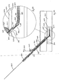
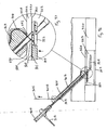
- the medical device comprises an elongate engagement element 1, a protective sheath 2, as illustrated in Figs. 1 to 5 , and an incising element 3, as illustrated in Figs. 6 to 9 .
- the engagement element 1 comprises a retaining element, which is provided in this case as a balloon part 4, which is expandable, in this case inflatable, from a low-profile delivery configuration ( Figs. 1 and 2 ) to a deployed configuration ( Figs. 3 and 4 ), and is returnable, in this case deflatable, from the deployed configuration to the delivery configuration ( Fig. 5 ).
- the engagement element I is piercable through a flap 7 of tissue wall and through a wall 8 of the blood vessel 6.
- the retaining element part 4 is engagable with the flap 7 of tissue wall at a side of an incision 9 ( Fig. 33 ).
- the engagement element 1 may thus be employed to move the flap 7 to seal across an opening 10 through the incision 9.
- the engagement element 1 may be withdrawn from the flap 7 and from the wall 8 of the blood vessel 6.
- Figs. 1 to 5 The engagement element deployment technique is illustrated in Figs. 1 to 5 : Fig. 1 illustrates the undeployed engagement element 1; Fig. 2 illustrates the sheath 2 retracted to allow deployment; Fig. 3 illustrates the retaining element 4 inflation / expansion phase; Fig. 4 illustrates the sheath 2 retracted to leave the engagement element 1 in place; and Fig. 5 illustrates the retaining element 4 deflated to allow engagement element 1 removal.
- the protective sheath 2 is slidably movable relative to the engagement element 1 between a protecting configuration ( Fig. 1 ) and an uncovered configuration ( Figs. 4 and 5 ). In the protecting configuration, the sheath 2 extends over the engagement element 1 and covers the retaining element part 4 to protect the engagement element 1 and the balloon part 4.
- the medical device also comprises an outer sheath 200, which is extendable over the protective sheath 2 and over the engagement element 1 in a sliding co-axial manner.
- the outer sheath 200 is slidably movable relative to the protective sheath 2/engagement element 1 between an uncovered configuration ( Fig. 9 ) and a protecting configuration ( Fig. 20 ).
- the sheath 200 is especially useful for protecting the engagement element 1 during creation of the incision 9 in the wall of the blood vessel 6. In the uncovered configuration, the sheath 200 is retracted.
- a modified Seldinger technique is used to introduce the engagement element 1.
- a modified Seldinger technique is used to introduce the engagement element 1.
- the starting position with the needle 100 positioned above the skin ready for incision is illustrated in Fig. 5(a) .
- the needle 100 is used to puncture the skin and gain access to the vessel inner lumen 11 ( Fig. 5(b) ).
- the needle inner core 101 is removed and the engagement element 1 is introduced through the needle lumen and into the vessel 6 ( Fig. 5(c) ).
- the needle 100 is withdrawn from the vessel 6 and body, and the engagement element 1 is left in place in the lumen 11 ( Fig. 5(d) ).
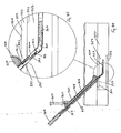
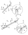
- the incising element 3 is suitable for creating the incision 9 in the wall 8 of the blood vessel 6 through which the engagement element 1 has been pierced.
- the incising element 3 creates the incision 9 around the engagement element 1 and the protective sheath 2 pierced through the wall 8 ( Fig. 20 ).
- the incising element 3 is provided in the form of a scissors-like arrangement 12 ( Figs. 8 and 9 ).
- the scissors 12 is movable between an open configuration ( Fig. 16 ) and a closed configuration ( Fig. 20 ) to create the incision 9 in the wall 8 of the blood vessel 6 around the engagement element I and the outer sheath 200.
- the scissors 12 In the closed configuration, the scissors 12 has an opening 5 for receiving the engagement element 1 and the outer sheath 200 extending through the incising device 3 ( Fig. 20 ).
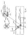
- the incising element 3 creates the incision 9 with the longitudinal axis A-A of the incision 9 inclined relative to the plane of the wall 8 of the blood vessel 6.
- the inclined incision 9 ensures that the flap 7 of tissue wall is created at the side of the incision 9, as illustrated in Figs. 25 and 28 .
- the longitudinal axis A-A may be inclined at an angle in the range of from 10° to 80° relative to the plane of the wall 8, and is preferably inclined at an angle of approximately 45°.
- the medical device may be employed in performing a method of accessing an interior 11 of the blood vessel 6.
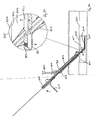
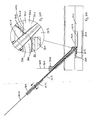
- the engagement element 1 is pierced through the wall 8 of the blood vessel 6, and the incising element 3 is positioned exterior of the blood vessel 6 with the scissors 12 inclined relative to the plane of the wall 8 of the blood vessel 6 ( Figs. 6 to 9 ).
- the outer sheath 200 is then pushed distally over the engagement element 1 to cover the retaining element part 4 ( Figs. 10 to 12 ).
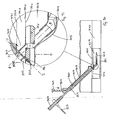
- the scissors 12 in the open configuration is pushed distally through the wall 8 ( Figs. 13 and 16 ), and the scissors 12 is moved from the open configuration to the closed configuration ( Figs. 17 to 20 ).
- the incision 9 through the wall 8 is created around the engagement element 1 and the outer sheath 200 both of which extend through the opening 5 in the closed scissors 12 ( Fig. 20 ).
- the incision 9 is created inclined to the plane of the wall 8, with the flap 7 of tissue wall formed at the side of the incision 9.
- the scissors 12 may then be moved from the closed configuration to the open configuration and pulled proximally out of the incision 9 ( Figs. 21 to 23 ).
- the incising element 3 and the outer sheath 200 may be withdrawn ( Figs. 24 to 26 ).
- the engagement element I is pierced through the flap 7 of tissue wall and through the wall 8 of the blood vessel 6 at the opposite side of the incision 9.
- the guidewire 14 is introduced into the interior 11 through the incision 9 prior to the introduction of the introducer sheath 13.
- an introducer sheath 13 engages the flap 7 and pushes the flap 7 distally ( Fig. 29 ).
- the flap 7 is moved aside to form the opening 10 to the interior 11 of the blood vessel 6 ( Fig. 30 ).
- the flap 7 moves relative to the wall 8 of the blood vessel 6 in a substantially hinging manner from a sealing configuration, in which the flap 7 seals across the opening 10 ( Fig. 28 ), to an access configuration, in which the flap 7 is moved aside to reveal the opening 10 ( Fig. 30 ).
- the axis of hinging of the flap 7 is substantially parallel to the plane of the wall 8. In the access configuration, the flap 7 is located within the interior 11 of the blood vessel 6.
- One or more medical devices such as the introducer sheath 13, and/or a guidewire 14, and/or a guide catheter, and/or a delivery catheter may therefore be inserted into the interior 11 of the blood vessel 6 through the opening 10 to access the interior 11, and a medical procedure may be performed within the interior 11 of the blood vessel 6 using the introducer sheath 13/guidewire 14/guide catheter/delivery catheter.
- the introducer sheath 13, and/or any other medical devices are withdrawn from the interior I 1 of the blood vessel 6 through the opening 10 ( Fig. 31 ).
- the retaining element part 4 is inflated from the delivery configuration to the deployed configuration ( Fig. 32 ), and the engagement element 1 is pulled proximally until the balloon part 4 engages the flap 7 ( Fig. 33 ).
- the flap 7 is pulled proximally until the flap 7 moves back across the opening 10 to seal across the opening 10 ( Fig. 34 ).
- the flap 7 moves relative to the wall 8 of the blood vessel 6 in a substantially hinging manner from the access configuration ( Fig. 30 ) to the sealing configuration ( Fig. 34 ). In the sealing configuration, the flap 7 engages the wall 8 of the blood vessel 6 at the opposite side of the incision 9.
- the engagement element 1 may remain in position ( Fig. 35 ).
- An anchoring element 110 is threaded onto the engagement element 1 and positioned on the external wall of the vessel 6.
- the anchoring element 110 serves to secure the incision area 10 and seal the vessel wall 8.
- the anchoring element 110 may be of a biodegradable polymer which slides down over the engagement element 1.
- the retaining element part 4 may be deflated from the deployed configuration to the delivery configuration, and the engagement element I may be withdrawn from the flap 7 and from the wall 8 of the blood vessel 6.
- the engagement element 1 may be provided with alternative means of engaging the flap 7.
- alternative means of moving a part of the engagement element 1 between the delivery configuration and the deployed configuration may be employed, for example, by expanding / contracting the part of the engagement element, instead of employing the expandable retaining element part 4.
- the part of the engagement element 1 may be moved from the delivery configuration to the deployed configuration to engage the flap 7. After sealing across the opening 10, the engagement element I may remain in position.
- the part of the engagement element may be biodegradable/bioresorbable.
- the medical device of Figs. 1 to 35 is an example of the double trap system which captures both sides/vessel wall flaps of the incision site 9 with a threaded through element, for example, the engagement element 1 with the expandable retaining element 4.
- the cutter 3 makes the incision 9 without cutting through the engagement element 1 which is put in place in the vessel wall 8 prior to the cutting step. This is accomplished by deploying a protective sheath 2 to cover and protect the engagement element 1 before the cutting plunger 3 is activated. Once activated the scissors 12 cuts through the vessel wall 8 with the scissor blades opened.
- the blades When the blades encounter the sheath 2 protecting the engagement element 1, they 'scissor' around the protective sheath 2 and cleanly cut the tissue 8 leaving a smooth incision 9 in the vessel 6.
- the scissors 12 opens and is retracted into the body of the cutting device 3.
- the first operation used is the Seldinger technique.
- a needle is used to puncture the vessel wall 8 and deliver a device such as an engagement element through the lumen of the needle into the vessel 6. Once this is completed, the needle is removed from the patient and the engagement element is left in place.
- the next sequence of events is for the delivery of the introducer sheath 13 and the guidewire 14. This sequence is shown in Figs. 29 and 30 .
- the incising element of the medical device may be provided in a number of possible configurations.
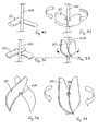
- the incising element may have a scissors type cutter arrangement 20, as illustrated in Figs. 36 to 39 , or an alternative scissors type cutter arrangement 21, as illustrated in Figs. 40 and 41
- the incising element may have a sliding type cutter arrangement 22, as illustrated in Figs. 42 and 43 , or an alternative sliding type cutter arrangement 23, as illustrated in Figs. 44 and 45
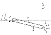
- the incising element may have a push/pull type cutter arrangement 24, as illustrated in Figs. 46 to 48 , or an alternative push/pull type cutter arrangement 25, as illustrated in Figs. 49 to 52 .
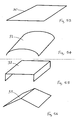
- the incision created in the wall 8 of the blood vessel 6 may have one of a variety of possible profiles.
- the incision may have a linear profile 30 ( Fig. 53 ), or an arch profile 31 ( Fig. 54 ), or a channel profile 32 ( Fig. 55 ), or a triangular profile 33 ( Fig. 56 ).
- These incision profiles may be achieved by suitable profiles on the incising element. It will be appreciated that a broad range of shapes from linear to angled, such as square, pentagon, dodecahedron, to a smooth curved arch may be employed.
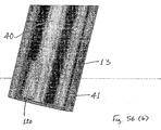
- Figs. 56(a) to 68 there is illustrated another medical device which is similar to the medical device described previously with reference to Figs. 1 to 35 , and similar elements in Figs. 56(a) to 68 are assigned the same reference numerals.
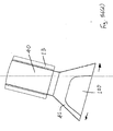
- the incising element 40 comprises a frusto-conical catheter 41 at the distal end of the incising element 40.
- the engagement element 1 is introduced into the interior 11 in a manner similar to that described previously with reference to Figs. 5(a) to 5(d) .
- the incising element 40 is advanced concentrically over the engagement element 1 which is pierced through the wall 8 of the blood vessel 6, in this case, to create the incision 9 in the wall 8.
- the protective sheath is therefore not required in this case.
- the punch cut device comprises an outer sheath element 13, within which is housed an expandable cutting element 41 and mechanisms 40 to activate and withdraw the cutting element 41.
- the cutting element blade system 41 will expand outwardly, increasing its diameter when pushed distally from the outer protective sheath 13 ( Figs. 56(c) and 56(d) ).
- This design of cutting element 41 can be accomplished by, for example, using a shape memory system with metal and polymer components, which when unrestrained expand radially to take the shape of a cone.
- the cutting element blade 41 is designed with a recessed notch 120 at which the vessel wall 8 is not cut. This ensures that there is a secure connection of the vessel wall 8 to the cut wall flap 7.
- the punch cut device has internal lumens which can accommodate guidewires, engaging elements or similarly dimensioned devices.
- the mode of operation of the punch cut device is as follows:
- the cutting element 41 is retracted in its protective sheath 13 ( Figs. 56(a) and 56(b) ).
- the cutting element 41 As the cutting element 41 is activated, it emerges from the distal end of the protective sheath 13 and exposes the cutting element 41 which expands radially.
- the shape of the cutting element 41 is such as to allow a portion of the vessel wall 8 to remain un-cut even when it is activated fully. This uncut portion forms the anchor for the tissue flap 7 and is an integral part of the system.
- Another example of this cutter is shown in Fig. 56(e) where the non-cutting slot 120 is extended the full length of the cutting blade 41. This will allow the device to be used with thin vessel walls.
- the longitudinal axis of the incising element 40 is not necessarily inclined relative to the plane of the wall 8 of the blood vessel 6.
- the access channel is initially formed using the modified Seldinger technique, where the trapping element 1 acts as a guidewire for the introduction of the cutting device 40.
- the cutting device 40 unlike in the normal Seldinger technique which uses a dilator tip with the introduction sheath to open the channel and push through the vessel, will have a flat tip introducer system which will butt up against the wall of the vessel 6. Often surgeons use a scalpel to nick the skin at the initial puncture site so as to allow easier entry of the introducer sheath through the skin in through the tissue of the vessel 6.
- the cutter 41 is then pushed distally through the wall 8 ( Figs. 58 to 60 ).
- the incision 9 is created inclined to the plane of the wall 8, with the flap 7 of tissue wall formed at the side of the incision 9.
- the cutter 41 may then be pulled proximally out of the incision 9 ( Fig. 61 ).
- the engagement element 1 is pierced through the flap 7 of tissue wall only, in this case, and is not pierced through the wall 8 of the blood vessel 6 at the opposite side of the incision 9.
- Figs. 57 to 68 illustrate the wedge/inverted cone device, which is an example of a single trap system where the cutter 41 is an inverted cone, with a slot removed, which is housed in the introducer sheath 13.
- the engagement element device 1 is in place prior to insertion of the cutter device 41, and the cutter device 41 is guided down the tissue channel over the engagement element 1 for placement of the device on the outside of the vessel wall 8.
- the cutter 41 will cut through the vessel wall 8 while leaving a strip of wall uncut and attached to the body of the vessel wall 8. This strip acts as an anchor tag which, along with the engagement element 1, guides the sealing element 7 back accurately into the opening 10 created by the cutting blade 41 in the vessel wall 8.
- the first operation used is the Seldinger technique.
- a needle is used to puncture the vessel wall 8 and deliver a guidewire through the lumen of the needle into the vessel 6. Once this is completed, the needle is removed from the patient and the guidewire is left in place.
- the engagement element I is introduced into the interior 11 in a manner similar to that described previously with reference to Figs. 5(a) to 5(d) .
- Fig. 69 illustrates the tissue tract closure step.
- the tissue tract can be protected using an adhesive pad element 120 which can include some antibiotic and thrombogenic substances and may be biodegradable.
- the engagement element 1 may be trimmed to below the skin surface and the adhesive pad 120 would be placed over the tissue tract opening to the skin, securing the site from contamination and promoting healing ( Fig. 69 ).
- the device may have a precise marking on it to clearly indicate the correct positioning of the cutting device 40 once it is butted up to the outside of the artery wall 8. Also, the direction of intended travel of the cutting blade 41 may be clearly marked on the device.
- the device 300 comprises a closure element 301, a grasping element 302 for grasping the closure element 301, a guide element 303 for guiding passage of the grasping element 302, and a delivery element 304 for delivering the closure element 301 into an internal lumen 323 of a blood vessel 320.
- the closure element 301 comprises a suture 305, a snap-fit engagement feature 306 at a proximal end of the suture 305, and an engagement foot 307 at a distal end of the suture 305.
- the engagement foot 307 may be made up of a bioabsorbable material, such as polyglycolic acid (PGA), polylactic acid (PLA), Polyethylene Glycol (PEG), polydioxanone bioabsorbable Polyurethane, or combinations or copolymers thereof.
- the suture 305 may be made up of a biodegradable polymer suture, such as polyglycolic acid (PGA), polylactic acid (PLA), polydioxanone, or combinations or copolymers thereof.
- the grasping element 302 comprises a flexible, elongate member 308, a handle 309 at a proximal end of the elongate member 308, and a snap-fit engagement feature 310 at a distal end of the elongate member 308.
- the engagement feature 310 of the grasping element 302 is inter-engageable with the engagement feature 306 of the closure element 301 in a snap-fit manner to enable the grasping element 302 to grasp the closure element 301.
- the grasping element 302 may be made of a superelastic material, such as nitinol, or may be made from stainless steel, or a kink resistant stiff polymer, such as PEEK.
- the delivery element 304 comprises a main body portion 313, a distal nose 314 at a distal end of the main body portion 313, and a proximal handle 315 at a proximal end of the main body portion 313.
- the distal nose 314 is rotatably movable relative to the main body portion 313 in a hinging manner.
- the distal nose 314 defines a reception space for carrying the engagement foot 307 of the closure element 301.
- the delivery element 304 also comprises an engagement foot 316 which is rotatably movable relative to the main body portion 313 in a hinging manner between a low-profile delivery configuration ( Fig. 72 ) and a protruding engagement configuration ( Fig. 73 ).
- the proximal handle 315 is rotatably movable relative to the main body portion 313 in a hinging manner to control movement of the engagement foot 316.
- the engagement foot 316 of the delivery element 304 carries the engagement feature 306 of the closure element 301.
- the guide element 303 comprises a first lumen 311 extending therethrough, through which the grasping element 302 may pass.
- the guide element 303 also comprises a second lumen 312 extending therethrough, through which the main body portion 313 of the delivery element 304 may extend.
- the device 300 may be employed to perform an interventional procedure on a blood vessel 320, as illustrated in Figs. 74 to 121 .
- the blood is flowing through the blood vessel 320 in the direction of arrow E in Figs. 74 and 75 .
- a tubular needle 321 is extended through the wall 322 of the blood vessel 320 from the external surface 324 of the blood vessel 320 to the internal lumen 323 of the blood vessel 320 ( Fig. 74 ).
- a puncture opening 330 is created through the blood vessel wall 322, with a first part 331 of the blood vessel wall 322 on a first side of the opening 330, and a second part 332 of the blood vessel wall 322 on a second side of the opening 330.
- the longitudinal axis B-B of the opening 330 subtends an acute angle, in this case approximately 45°, with the longitudinal axis of the internal lumen 323 of the blood vessel 320.
- a guidewire 325 is introduced through the needle 321 into the internal lumen 323 of the blood vessel 320 ( Fig. 76 ), and the needle 321 is then removed ( Fig. 78 ).
- the device 300 is threaded over the guidewire 325, with the distal nose 314 of the delivery element 304 arranged in-line with the main body portion 313, and with the engagement foot 316 of the delivery element 304 in the delivery configuration.
- the engagement foot 304 of the closure element 301 is carried by the distal nose 314 of the delivery element 304, and the engagement feature 306 of the closure element 301 is carried by the engagement foot 316 of the delivery element 304.
- the device 300 is advanced over the guidewire 325 to dilate the opening 330 until the distal nose 314 is within the internal lumen 323 of the blood vessel 320 ( Fig. 80 ). In this manner the closure element 301 is inserted through the opening 330 into the internal lumen 323 of the blood vessel 320.
- the distal nose 314 of the delivery element 304 is rotated relative to the main body portion 313 ( Fig. 82 ), and the guidewire 325 is removed ( Fig. 84 ).
- the distal nose 314 may be made of a flexible piece of tubing.
- the distal nose 314 may be rotated relative to the main body potion 313 by means of the flexible tubing deforming upon engagement of the distal nose 314 with the internal surface 326 of the blood vessel 320.
- the engagement foot 316 of the delivery element 304 is rotated relative to the main body portion 313 from the delivery configuration to the engagement configuration by rotating the proximal handle 315 relative to the main body portion 313 ( Fig. 86 ).
- the delivery element 304 is slid proximally through the second lumen 312 of the guide element 303, while the portion of the guide element 303 remains substantially fixed, until the engagement foot 316 of the delivery element 304 engages the internal surface 326 of the blood vessel 320 ( Fig. 88 ).
- this maintains the position of the closure element 301 substantially fixed within the internal lumen 323 of the blood vessel 320 prior to grasping.
- the handle 309 of the grasping element 302 is pushed distally while the position of the guide element 303 remains substantially fixed, which causes the engagement feature 310 of the grasping element 302 to pass through the first part 331 of the blood vessel wall 322, across the opening 330, through the second part 332 of the blood vessel wall 322, and into engagement with the engagement feature 306 of the closure element 301 ( Fig. 90 ). In this manner the grasping element 302 grasps the closure element 301 within the internal lumen 323.
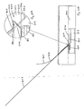
- the axis C-C along which the engagement feature 310 of the grasping element 302 passes subtends an acute angle, preferably in the range of from 5° to 65°, most preferably in the range of from 15° to 55°, and in this case approximately 30°, with the longitudinal axis of the internal lumen 323 of the blood vessel 320.
- the axis C-C subtends an angle ⁇ in the range of from 70° to 130°, preferably 80° to 120°, and in this case approximately 105° with the longitudinal axis B-B of the opening 330.
- 91 illustrates a transverse axis D-D of the internal lumen 323 which extends perpendicular to the longitudinal axis of the internal lumen 323 and through the point of intersection of the axis B-B and the axis C-C.
- the intersection point of the axis B-B with the external surface 324 of the blood vessel 320 is on one side of the axis D-D
- the intersection point of the axis C-C with the external surface 324 of the blood vessel 320 is on the opposite side of the axis D-D.
- the axis B-B effectively extends in an opposite direction to axis C-C.
- the axis C-C extends in the direction of blood flow E
- the axis B-B extends in the opposite direction to blood flow E.
- the handle 309 of the grasping element 302 is then pulled proximally while the position of the guide element 303 remains substantially fixed, which causes part of the closure element 301 to be retracted through the second part 332 of the blood vessel wall 322, across the opening 330, through the first part 331 of the blood vessel wall 322, and into the first lumen 311 of the guide element 303 ( Fig. 92 ).
- the closure element 301 is retracted along the axis C-C. Pulling of the handle 309 of the grasping element 302 proximally also causes the engagement foot 307 of the closure element 301 to be released from the distal nose 314 ( Fig. 92 ).
- the handle 309 of the grasping element 302 continues to be pulled proximally until the engagement foot 307 of the closure element 301 engages the internal surface 326 of the blood vessel 320 ( Fig. 96 ).
- the engagement foot 316 of the delivery element 304 is rotated relative to the main body portion 313 from the engagement configuration to the delivery configuration by rotating the handle 315 relative to the main body portion 313 ( Fig. 98 ), and the guidewire 325 is reintroduced into the internal lumen 323 of the blood vessel 320 by threading through the device 300 ( Fig. 100 ).
- the suture 305 extends across a slot 360 in the hypotube main body portion 313. By rotating the hypotube main body portion 313 through 90 degrees, this will push the suture 305 out of the slot 360, thus allowing the delivery element 304 to be removed ( Fig. 105 ).
- the distal nose 314 of the delivery element 304 is rotated relative to the main body portion 313 until the distal nose 314 is in-line with the main body portion 313, and the delivery element 304 is removed from the internal lumen 323 of the blood vessel 320 ( Fig. 106 ).
- the guide element 303 and the grasping element 302 are also removed, leaving the guidewire 325 extending through the opening 330 into the internal lumen 323 of the blood vessel 320 and the suture 305 extending through the blood vessel wall 322 into the internal lumen 323 ( Fig. 108 ).
- An introducer sheath 340 may be threaded over the guidewire 325 and advanced through the opening 330 to dilate the opening 330, and into the internal lumen 323 of the blood vessel 320 ( Fig. 110 ).
- One or more medical devices such as guidewires, delivery catheters, angioplasty catheters, retrieval catheters, diagnostic catheters, may be delivered through the introducer sheath 340 in the opening 330 into the internal lumen 323 of the blood vessel 320 to perform one or more interventional procedures within the internal lumen 323 of the blood vessel 320. After completion of the interventional procedures, the introducer sheath 340 and the guidewire 325 are removed.
- the suture 305 is pulled proximally until the engagement foot 307 of the closure element 301 engages the internal surface 326 of the blood vessel 320 on the first side of the opening 330 and on the second side of the opening 330.
- An external plug 341 is then threaded over the suture 305 and advanced distally into engagement with the external surface 324 of the blood vessel 320 on the first side of the opening 330 and on the second side of the opening 330 ( Fig. 112 ).
- the engagement foot 307 of the closure element 301 exerts a compressive force on the internal surface 326 of the blood vessel 320
- the plug 341 exerts a compressive force on the external surface 324 of the blood vessel 320.
- An external anchor 342 is threaded over the suture 305 and advanced distally into engagement with the plug 341 to anchor the plug 341 in position engaging the external surface 324 of the blood vessel 320 ( Figs. 115 and 118 ).
- a protective element 343 is mounted at the proximal end of the tissue tract 344 ( Fig. 120 ).
- the external plug 341 may be made of PGA, PLA, collagen, or PEG.
- the tubular needle type cutter 321 creates the incision 330 for delivery of the securement feature 301 across this incision 330.
- the tubular needle 321 is non-coring and achieves a slit 330 and allows for easy delivery of a guidewire 325 and minimal blood loss during the setting of the securement feature 301.
- the securement feature 301 may be delivered across the incision 330 through a slot either in the needle 321 or a subsequent tube that is placed through the incision 330.
- An important aspect is the control of the distance from the internal lumen 323 of the artery 320 to the point at which the securement feature 301 crosses the incision 330.
- the intravascular positioning foot 316 is a means of controlling this distance accurately. This may be an integrated part of the tubular needle 321 or preferably once the incision 330 is made, the tube 304 which contains the foot 316 is delivered over the introducer guidewire 325.
- the securement element delivery device 303 may be slid over the positioning foot 304 and locked into position; the securement element 301 may be delivered across the incision 330 through a slot/hole in the positioning foot tube 304.
- the device 304 is removed and the interventional procedure is carried out.
- the suture 305 is moved aside as the dilator/introducer sheath 340 is delivered through the arteriotomy 330.
- the incision 330 is sealed by pulling on the suture 305 and then advancing and locking into position the bioabsorbable element 341 which has haemostatic properties.
- This extravascular component 341 may be in the form of a soft fibre mesh and the compression could be achieved by the extra bioabsorbable component 342 which is rigid and has a feature which locks onto the suture 305.
- the device 300 may involve the needle 310 that crosses the cut artery 320 and picks up the suture 305 that is stored in the flexible tube that is already within the artery 323.
- a possible way of picking up the suture 305 and drawing it back may be to mount a coiled spring 306 on the end of the suture 305 and have a feature 310 on the needle 302 which will lock into this spring 306.
- FIGs. 122 to 127 there is illustrated another interventional medical closure device 350, which is similar to the device 300 of Figs. 70 to 121 , and similar elements in Figs. 122 to 127 are assigned the same reference numerals.
- the guide element 303 comprises a distal outlet port 351 out of which the engagement feature 310 of the grasping element 302 may pass out of the first lumen 311, and a main body portion 352.
- the outlet port 351 is rotatably movable relative to the main body portion 352 between a low-profile, delivery configuration ( Fig. 122 ) and a protruding, guiding configuration ( Fig. 124 ).
- the outlet port 351 is rotatable in the range of from 70° to 130°, preferably in the range of from 80° to 120°, and in this case approximately 105°.
- the device 350 is similar to the device 300 of Figs. 70 to 121 but utilises the expanding arm 351. This reduces the profile of the device 350 that has to be inserted through the skin and tissue tract 344.
- the expandable arm 351 is only deployed once the device 350 is in position at the vessel wall, and the arm 351 is retracted once the suture 305 has been picked up.
Description
- This invention relates to an interventional medical closure device. This invention also relates to a medical device suitable for use in accessing an interior of a body part. In one embodiment this invention relates to a vessel access and closure device for making and closing access sites in human and animal tissue. A particular example of the invention is a vascular lumen access and closure device.
- With recent advances in medical device technology, there has been a growth in the use of minimally invasive surgical techniques for both diagnostic and therapeutic applications by cardiologists and radiologists. For some classes of vascular procedure, they have become the treatment of choice over conventional surgery. With a minimally invasive procedure, it is often necessary to gain access to the blood vessels in order to deliver various medical devices into the vasculature such as wires, balloon catheters and other medical devices in order to treat a disease.
- A commonly used procedure with which to gain access to the vascular system for minimally invasive surgery is known as the Seldinger technique. This technique involves using a small gauge hollow needle to puncture the skin and to enter the desired blood vessel. Then, a small guidewire is introduced through the lumen of the needle into the blood vessel and the needle is removed, leaving the wire in place. An introducer sheath with dilator is inserted over the guidewire and pushed through the puncture into the vessel, opening a hole in the vessel wall by forcing the sides of the puncture laterally apart to accommodate the introducer sheath in the opening. The dilator is removed and the introducer sheath, which usually contains a haemostasis valve to stop bleedback from the blood vessel, is left in place. This provides the access port for delivery of diagnostic and therapeutic catheters and medical devices to the vasculature.
- Examples of minimally invasive surgery procedures include angiography, balloon angioplasty and stenting, intravascular imaging and thrombectomy. At the conclusion of the interventional procedure, the medical devices used are removed from the body including the catheters, guidewires and introducer sheaths, and it is necessary to close the puncture in the vessel created at the beginning of the procedure. This is done in order to provide haemostasis and to promote healing of the vessel wall and tissue tract.
- One treatment to provide haemostasis at the puncture site post procedure is by applying external manual compression for a period of time to the patient at the site of the puncture. The duration and force required depends on the size and location of the puncture, the patient's anatomy, and the amount of anticoagulation treatment administered to the patient. The time required for the manual compression may be long and this may lead to considerable patient discomfort and extend the time to ambulation and the duration of stay in the hospital. This may increase hospital staff time and the cost of health care for the patient. Often supplemental external compression such as sandbags, body clamps and pneumatic devices are used to promote haemostasis in the vessel wall and tissue tract.
- Complications may arise with compressive techniques, as too much pressure may restrict or occlude the blood vessel, potentially leading to ischemia and thrombus formation in the vessel. These techniques can have unpredictable post procedural haemorrhaging requiring additional interventions by the doctors and nurses. Another known treatment is to employ a wound closure device to facilitate the repair of wounds caused by minimally invasive surgical access of the vasculature of the body. A variety of vascular sealing devices have been developed such as: closure devices which include suture mediated, collagen/gel based and staple devices; and assisted compression devices which include mechanical and pressure-assisted compression devices and topical patches.
- However these vascular sealing devices suffer from a number of disadvantages, such as:
- It may be necessary to repair a puncture site without having any control on the positioning in the vessel, the size or the shape of the puncture;
- These devices may lead to puckering of the vessel wall after deployment, leading to the risk of thrombosis and vessel lumen narrowing;
- These devices may leave a permanent implant in the closure site on the vessel wall;
- Considerable patient discomfort may be caused during the deployment of the devices;
- These devices may require additional dilation of the wound post procedure in order to accommodate the size of a staple/ clip delivery system;
- It may be difficult to effect good closure if the device is poorly placed and it restricts access options for repairs;
- The sealing element may be deployed inside the vessel thereby restricting or occluding blood flow;
- The sealing material may contain thrombogenic material which may form thrombus at the vessel puncture and lead to emboli;
- There is a risk of embolisation of the gel or foam material in the blood stream due to inaccurate deployment or migration post delivery to the tissue tract;
- Ineffective closure of the puncture wound in the blood vessel may occur as the material is deployed in the tissue tract with an increased risk of haemotoma;
- These devices are often designed to leave materials on the inside of the blood vessel, thereby increasing the risk of blood flow restriction or occlusion;
- A disk may detach from an anchor element and travel distal to the wound site and cause blood flow restrictions or occlusions, potentially requiring surgical intervention;
- There is a risk of haematoma forming in the tissue tract;
- There is a risk of haemorrhage due to continued patency of the puncture in the vessel wall;
- These devices may require significant manual compression before and during use.
- This invention is therefore aimed at providing an improved medical device which will address at least some of the disadvantages encountered in conventional treatments.
- The device is defined in the independent claim.
- The invention will be more clearly understood from the following description of some embodiments thereof, given by way of example only, with reference to the accompanying drawings, in which:
-
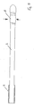
Fig. 1 is a partially cross-sectional, side view of a distal end of an engagement element of a medical device; -
Figs. 2 to 5 are partially cross-sectional, side views of the engagement element ofFig. 1 , in use; -
Figs. 5(a) to 5(d) are partially cross-sectional, side views illustrating introduction of the engagement element ofFig. 1 into an interior of a body part; -
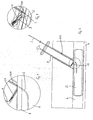
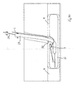
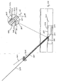
Fig. 6 is a partially cross-sectional, side view of the engagement element ofFig. 1 and an incising element of the medical device, in use at a first step of a method of accessing an interior of a body part; -
Fig. 7 is an enlarged, cross-sectional, side view of the engagement element and the incising element ofFig. 6 ; -
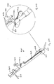
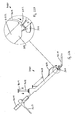
Figs. 8 and9 are enlarged, cut-away, perspective views of the engagement element and the incising element ofFig. 6 ; -
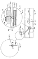
Figs. 10 to 12 are views similar toFigs. 6 to 8 of the engagement element and the incising element ofFig. 6 , in use at a second step of the method. -
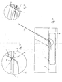
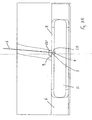
Figs. 13 to 16 are views similar toFigs. 6 to 9 of the engagement element and the incising element ofFig. 6 , in use at a third step of the method; -
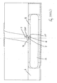
Figs. 17 to 20 are views similar toFigs. 6 to 9 of the engagement element and the incising element ofFig. 6 , in use at a fourth step of the method; -
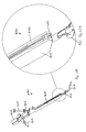
Figs. 21 to 23 are views similar toFigs. 6 to 8 of the engagement element and the incising element ofFig. 6 , in use at a fifth step of the method; -
Figs. 24 to 27 are views similar toFigs. 6 to 9 of the engagement element ofFig. 6 , in use at a sixth step of the method; -
Figs. 28 to 30 are partially cross-sectional, side views illustrating introduction of an introducer sheath and a guidewire; -
Fig. 31 is a partially cross-sectional, side view illustrating removal of the introducer sheath and the guidewire; -
Fig. 32 is a partially cross-sectional, side view illustrating activation of a trapping matter of the engagement element ofFig. 6 ; -
Fig. 33 is a partially cross-sectional, side view illustrating trapping of a flap using the engagement element ofFig. 6 ; -
Fig. 34 is a partially cross-sectional, side view illustrating closure of the flap using the engagement element ofFig. 6 ; -
Figs. 35 and35(a) are partially cross-sectional, side views illustrating anchoring of the flap; -
Fig. 36 is a perspective view of an incising element in an open configuration and an engagement element of the medical device according to the invention; -
Fig. 37 is a perspective view of the incising element ofFig. 36 in a closed configuration and the engagement element ofFig. 36 ; -
Fig. 38 is a plan view of the incising element ofFig. 36 in the open configuration and the engagement element ofFig. 36 ; -
Fig. 39 is a plan view of the incising element ofFig. 36 in the closed configuration and the engagement element ofFig. 36 ; -
Figs. 40 and 41 are views similar toFigs. 36 and 37 of an incising element and an engagement element of another medical device according to the invention; -
Figs. 42 and 43 are views similar toFigs. 36 and 37 of an incising element and an engagement element of another medical device according to the invention; -
Figs. 44 and 45 are views similar toFigs. 36 and 37 of an incising element and an engagement element of another medical device according to the invention; -
Figs. 46 to 48 are perspective views of an incising element and an engagement element of another medical device according to the invention, in use; -
Figs. 49 to 52 are perspective views of an incising element and an engagement element of a further medical device according to the invention, in use; -
Fig. 53 is a perspective view illustrating the profile of an incision in a method of accessing an interior of a body part; -
Figs. 54 to 56 are perspective views illustrating alternative incision profiles; -
Figs. 56(a) to 56(e) are perspective views of an incising element of another medical device; -
Figs. 57 to 69 are partially cross-sectional, side views illustrating another method of accessing an interior of a body part using the incising element ofFigs. 56(a) to 56(e) ; -
Figs. 70 and 71 are perspective views of an interventional medical closure device; -
Figs. 72 and 73 are cross-sectional, side views of the device ofFigs. 70 and 71 ; -
Figs. 74 to 93 are partially cross-sectional, side views illustrating steps in a method of performing an interventional procedure using the device ofFigs. 70 and 71 ; -
Fig. 94 is a perspective view of the device ofFig. 70 and 71 in the step illustrated inFigs. 92 and 93 ; -
Fig. 95 is an enlarged, perspective view of a part of the device ofFig. 94 ; -
Figs. 96 to 101 are partially cross-sectional, side views illustrating further steps in the method of performing an interventional procedure
using the device ofFigs. 70 and 71 ; -
Fig. 102 is a side view of the device ofFigs. 70 and 71 in the step illustrated inFigs. 100 and 101 ; -
Fig. 103 is an enlarged, side view of a part of the device ofFig. 102 ; -
Fig. 104 is a perspective view of the device ofFigs. 70 and 71 in the step illustrated inFigs. 100 and 101 ; -
Fig. 105 is an enlarged, perspective view of a part of the device ofFig. 104 ; -
Figs. 106 to 121 are partially cross-sectional, side views of further steps in the method of performing an interventional procedure using the device ofFigs. 70 and 71 ; -
Fig. 122 is a perspective view of the another interventional medical closure device in a delivery configuration; -
Fig. 123 is an enlarged, perspective view of a part of the device ofFig. 122 ; -
Figs. 124 and 125 are views similar toFigs. 122 and 123 of the device ofFig. 122 in a guiding configuration; -
Fig. 126 is a side view of the device ofFig. 122 in the guiding configuration; and -
Fig. 127 is an enlarged, side view of a part of the device ofFig. 126 . - Referring to the drawings and initially to
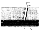
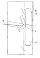
Figs. 1 to 35(a) thereof, there is illustrated a medical device, which is suitable for use in accessing an interior of a body part. The device is particularly suitable for accessing the interior of ablood vessel 6. The medical device comprises anelongate engagement element 1, aprotective sheath 2, as illustrated inFigs. 1 to 5 , and an incisingelement 3, as illustrated inFigs. 6 to 9 . - The
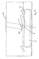
engagement element 1 comprises a retaining element, which is provided in this case as aballoon part 4, which is expandable, in this case inflatable, from a low-profile delivery configuration (Figs. 1 and2 ) to a deployed configuration (Figs. 3 and4 ), and is returnable, in this case deflatable, from the deployed configuration to the delivery configuration (Fig. 5 ). In the delivery configuration, the engagement element I is piercable through aflap 7 of tissue wall and through awall 8 of theblood vessel 6. In the deployed configuration the retainingelement part 4 is engagable with theflap 7 of tissue wall at a side of an incision 9 (Fig. 33 ). Theengagement element 1 may thus be employed to move theflap 7 to seal across anopening 10 through theincision 9. In the delivery configuration, theengagement element 1 may be withdrawn from theflap 7 and from thewall 8 of theblood vessel 6. - The engagement element deployment technique is illustrated in
Figs. 1 to 5 :Fig. 1 illustrates theundeployed engagement element 1;Fig. 2 illustrates thesheath 2 retracted to allow deployment;Fig. 3 illustrates the retainingelement 4 inflation / expansion phase;Fig. 4 illustrates thesheath 2 retracted to leave theengagement element 1 in place; andFig. 5 illustrates the retainingelement 4 deflated to allowengagement element 1 removal. - The
protective sheath 2 is slidably movable relative to theengagement element 1 between a protecting configuration (Fig. 1 ) and an uncovered configuration (Figs. 4 and5 ). In the protecting configuration, thesheath 2 extends over theengagement element 1 and covers the retainingelement part 4 to protect theengagement element 1 and theballoon part 4. - The medical device also comprises an
outer sheath 200, which is extendable over theprotective sheath 2 and over theengagement element 1 in a sliding co-axial manner. Theouter sheath 200 is slidably movable relative to theprotective sheath 2/engagement element 1 between an uncovered configuration (Fig. 9 ) and a protecting configuration (Fig. 20 ). - The
sheath 200 is especially useful for protecting theengagement element 1 during creation of theincision 9 in the wall of theblood vessel 6. In the uncovered configuration, thesheath 200 is retracted. - A modified Seldinger technique is used to introduce the
engagement element 1. When using devices to access vessels such asarteries 6, it is necessary to use a modified Seldinger technique in order to introduce theengagement element 1 into the interior or vesselinner lumen 11 from the skin. The starting position with theneedle 100 positioned above the skin ready for incision is illustrated inFig. 5(a) . Theneedle 100 is used to puncture the skin and gain access to the vessel inner lumen 11 (Fig. 5(b) ). With theneedle 100 in place, the needleinner core 101 is removed and theengagement element 1 is introduced through the needle lumen and into the vessel 6 (Fig. 5(c) ). Finally theneedle 100 is withdrawn from thevessel 6 and body, and theengagement element 1 is left in place in the lumen 11 (Fig. 5(d) ). - This then forms the guidance system for the delivery of the devices to the vessel wall for subsequent operations.
- The incising
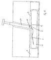
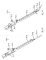
element 3 is suitable for creating theincision 9 in thewall 8 of theblood vessel 6 through which theengagement element 1 has been pierced. In particular the incisingelement 3 creates theincision 9 around theengagement element 1 and theprotective sheath 2 pierced through the wall 8 (Fig. 20 ). - In this case, the incising
element 3 is provided in the form of a scissors-like arrangement 12 (Figs. 8 and9 ). Thescissors 12 is movable between an open configuration (Fig. 16 ) and a closed configuration (Fig. 20 ) to create theincision 9 in thewall 8 of theblood vessel 6 around the engagement element I and theouter sheath 200. In the closed configuration, thescissors 12 has anopening 5 for receiving theengagement element 1 and theouter sheath 200 extending through the incising device 3 (Fig. 20 ). - As illustrated in
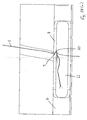
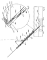
Figs. 22 and25 , the incisingelement 3 creates theincision 9 with the longitudinal axis A-A of theincision 9 inclined relative to the plane of thewall 8 of theblood vessel 6. Theinclined incision 9 ensures that theflap 7 of tissue wall is created at the side of theincision 9, as illustrated inFigs. 25 and28 . - The longitudinal axis A-A may be inclined at an angle in the range of from 10° to 80° relative to the plane of the
wall 8, and is preferably inclined at an angle of approximately 45°. - The medical device may be employed in performing a method of accessing an interior 11 of the
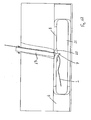
blood vessel 6. In use, theengagement element 1 is pierced through thewall 8 of theblood vessel 6, and the incisingelement 3 is positioned exterior of theblood vessel 6 with thescissors 12 inclined relative to the plane of thewall 8 of the blood vessel 6 (Figs. 6 to 9 ). Theouter sheath 200 is then pushed distally over theengagement element 1 to cover the retaining element part 4 (Figs. 10 to 12 ). - To create the
incision 9 in thewall 8 of theblood vessel 6, thescissors 12 in the open configuration is pushed distally through the wall 8 (Figs. 13 and16 ), and thescissors 12 is moved from the open configuration to the closed configuration (Figs. 17 to 20 ). In this manner theincision 9 through thewall 8 is created around theengagement element 1 and theouter sheath 200 both of which extend through theopening 5 in the closed scissors 12 (Fig. 20 ). Theincision 9 is created inclined to the plane of thewall 8, with theflap 7 of tissue wall formed at the side of theincision 9. - The
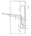
scissors 12 may then be moved from the closed configuration to the open configuration and pulled proximally out of the incision 9 (Figs. 21 to 23 ). The incisingelement 3 and theouter sheath 200 may be withdrawn (Figs. 24 to 26 ). As illustrated inFigs. 25 to 27 , the engagement element I is pierced through theflap 7 of tissue wall and through thewall 8 of theblood vessel 6 at the opposite side of theincision 9. - The
guidewire 14 is introduced into the interior 11 through theincision 9 prior to the introduction of theintroducer sheath 13. - To access the
interior 11 of theblood vessel 6, anintroducer sheath 13 engages theflap 7 and pushes theflap 7 distally (Fig. 29 ). By pushing theflap 7 distally, theflap 7 is moved aside to form theopening 10 to the interior 11 of the blood vessel 6 (Fig. 30 ). Theflap 7 moves relative to thewall 8 of theblood vessel 6 in a substantially hinging manner from a sealing configuration, in which theflap 7 seals across the opening 10 (Fig. 28 ), to an access configuration, in which theflap 7 is moved aside to reveal the opening 10 (Fig. 30 ). The axis of hinging of theflap 7 is substantially parallel to the plane of thewall 8. In the access configuration, theflap 7 is located within theinterior 11 of theblood vessel 6. - One or more medical devices, such as the
introducer sheath 13, and/or aguidewire 14, and/or a guide catheter, and/or a delivery catheter may therefore be inserted into the interior 11 of theblood vessel 6 through theopening 10 to access the interior 11, and a medical procedure may be performed within theinterior 11 of theblood vessel 6 using theintroducer sheath 13/guidewire 14/guide catheter/delivery catheter. - After completion of the medical procedure, the
introducer sheath 13, and/or any other medical devices, are withdrawn from the interior I 1 of theblood vessel 6 through the opening 10 (Fig. 31 ). To seal across theopening 10, the retainingelement part 4 is inflated from the delivery configuration to the deployed configuration (Fig. 32 ), and theengagement element 1 is pulled proximally until theballoon part 4 engages the flap 7 (Fig. 33 ). By further pulling of theengagement element 1 proximally, theflap 7 is pulled proximally until theflap 7 moves back across theopening 10 to seal across the opening 10 (Fig. 34 ). Theflap 7 moves relative to thewall 8 of theblood vessel 6 in a substantially hinging manner from the access configuration (Fig. 30 ) to the sealing configuration (Fig. 34 ). In the sealing configuration, theflap 7 engages thewall 8 of theblood vessel 6 at the opposite side of theincision 9. - After sealing across the
opening 10, theengagement element 1 may remain in position (Fig. 35 ). Ananchoring element 110 is threaded onto theengagement element 1 and positioned on the external wall of thevessel 6. The anchoringelement 110 serves to secure theincision area 10 and seal thevessel wall 8. The anchoringelement 110 may be of a biodegradable polymer which slides down over theengagement element 1. Alternatively the retainingelement part 4 may be deflated from the deployed configuration to the delivery configuration, and the engagement element I may be withdrawn from theflap 7 and from thewall 8 of theblood vessel 6. - It will be appreciated that the
engagement element 1 may be provided with alternative means of engaging theflap 7. For example alternative means of moving a part of theengagement element 1 between the delivery configuration and the deployed configuration may be employed, for example, by expanding / contracting the part of the engagement element, instead of employing the expandableretaining element part 4. - As a further alternative, the part of the
engagement element 1 may be moved from the delivery configuration to the deployed configuration to engage theflap 7. After sealing across theopening 10, the engagement element I may remain in position. The part of the engagement element may be biodegradable/bioresorbable. - The medical device of
Figs. 1 to 35 is an example of the double trap system which captures both sides/vessel wall flaps of theincision site 9 with a threaded through element, for example, theengagement element 1 with theexpandable retaining element 4. Thecutter 3 makes theincision 9 without cutting through theengagement element 1 which is put in place in thevessel wall 8 prior to the cutting step. This is accomplished by deploying aprotective sheath 2 to cover and protect theengagement element 1 before the cuttingplunger 3 is activated. Once activated thescissors 12 cuts through thevessel wall 8 with the scissor blades opened. When the blades encounter thesheath 2 protecting theengagement element 1, they 'scissor' around theprotective sheath 2 and cleanly cut thetissue 8 leaving asmooth incision 9 in thevessel 6. When the device is withdrawn, thescissors 12 opens and is retracted into the body of thecutting device 3. - To start the procedure, the first operation used is the Seldinger technique. Here a needle is used to puncture the
vessel wall 8 and deliver a device such as an engagement element through the lumen of the needle into thevessel 6. Once this is completed, the needle is removed from the patient and the engagement element is left in place. - The sequence of
Figs. 6 to 30 shows the following: - Step 1: The cutting
device 3 is delivered down the tissue tract from the skin to the outside of thevessel wall 8 over the engagement element which directs thecutter 3 to its correct location on the vessel wall 8 (Figs. 6 to 8 ).
Fig. 9 shows an exploded view of thescissors component 12 seated in its pocket in thecutting device 3. - Step 2: The
protective sheath 2 is deployed over the guidewire and the guidewire is exchanged with an engagement element 1 (Figs. 10 to 12 ). - Step 3: The plunger is activated and the
cutter 3 is delivered into thevessel wall 8 and around the protective sheath 2 (Figs 13 to 16 ). - Step 4: The plunger is pushed fully down and the
scissors 12 has wrapped around theprotective sheath 2, effecting a clean cut through the vessel wall 8 (Figs. 17 to 20 ). Step 5: The plunger is retracted and thecutting blades 12 are returned to their starting location in the cutting device body 3 (Figs. 21 to 23 ). - Step 6: The cutting
device 3 is withdrawn from the tissue tract and theengagement element 1 is left in the incision 9 (Figs. 24 to 27 ). - The next sequence of events is for the delivery of the
introducer sheath 13 and theguidewire 14. This sequence is shown inFigs. 29 and30 . - The incising element of the medical device may be provided in a number of possible configurations. For example, the incising element may have a scissors
type cutter arrangement 20, as illustrated inFigs. 36 to 39 , or an alternative scissorstype cutter arrangement 21, as illustrated inFigs. 40 and 41 , or the incising element may have a slidingtype cutter arrangement 22, as illustrated inFigs. 42 and 43 , or an alternative slidingtype cutter arrangement 23, as illustrated inFigs. 44 and 45 , or the incising element may have a push/pulltype cutter arrangement 24, as illustrated inFigs. 46 to 48 , or an alternative push/pulltype cutter arrangement 25, as illustrated inFigs. 49 to 52 . - The incision created in the
wall 8 of theblood vessel 6 may have one of a variety of possible profiles. For example, the incision may have a linear profile 30 (Fig. 53 ), or an arch profile 31 (Fig. 54 ), or a channel profile 32 (Fig. 55 ), or a triangular profile 33 (Fig. 56 ). These incision profiles may be achieved by suitable profiles on the incising element. It will be appreciated that a broad range of shapes from linear to angled, such as square, pentagon, dodecahedron, to a smooth curved arch may be employed. - In
Figs. 56(a) to 68 , there is illustrated another medical device which is similar to the medical device described previously with reference toFigs. 1 to 35 , and similar elements inFigs. 56(a) to 68 are assigned the same reference numerals. - In this case, the incising
element 40 comprises a frusto-conical catheter 41 at the distal end of the incisingelement 40. - The
engagement element 1 is introduced into the interior 11 in a manner similar to that described previously with reference toFigs. 5(a) to 5(d) . - The incising
element 40 is advanced concentrically over theengagement element 1 which is pierced through thewall 8 of theblood vessel 6, in this case, to create theincision 9 in thewall 8. The protective sheath is therefore not required in this case. - Referring to
Figs. 56(a) to 56(d) , the punch cut device comprises anouter sheath element 13, within which is housed anexpandable cutting element 41 andmechanisms 40 to activate and withdraw the cuttingelement 41. - The cutting
element blade system 41 will expand outwardly, increasing its diameter when pushed distally from the outer protective sheath 13 (Figs. 56(c) and56(d) ). - This design of cutting
element 41 can be accomplished by, for example, using a shape memory system with metal and polymer components, which when unrestrained expand radially to take the shape of a cone. - When used to make an
incision 9 on avessel wall 8, this results in a cone shaped cut 9 being formed in thevessel wall 8, with the smaller diameter cut on the outer wall of thevessel 6 and the larger diameter cut on the inside wall of the vessel 6 (Fig. 61 ). - The cutting
element blade 41 is designed with a recessednotch 120 at which thevessel wall 8 is not cut. This ensures that there is a secure connection of thevessel wall 8 to thecut wall flap 7. - The punch cut device has internal lumens which can accommodate guidewires, engaging elements or similarly dimensioned devices.
- The mode of operation of the punch cut device is as follows:
- In its starting position, the cutting
element 41 is retracted in its protective sheath 13 (Figs. 56(a) and56(b) ). - As the cutting
element 41 is activated, it emerges from the distal end of theprotective sheath 13 and exposes the cuttingelement 41 which expands radially. - As the
cutter 41 is pushed further distally to the end-stop, it continues to expand radially to its pre-set size and shape (Figs. 56(c) to 56(e) ). - When used to make an
incision 9 in ahollow vessel 6, the shape of the cuttingelement 41 is such as to allow a portion of thevessel wall 8 to remain un-cut even when it is activated fully. This uncut portion forms the anchor for thetissue flap 7 and is an integral part of the system. Another example of this cutter is shown inFig. 56(e) where thenon-cutting slot 120 is extended the full length of thecutting blade 41. This will allow the device to be used with thin vessel walls. - The longitudinal axis of the incising
element 40 is not necessarily inclined relative to the plane of thewall 8 of theblood vessel 6. - To create the
incision 9 in thewall 8 of theblood vessel 6, the access channel is initially formed using the modified Seldinger technique, where the trappingelement 1 acts as a guidewire for the introduction of the cuttingdevice 40. The cuttingdevice 40, unlike in the normal Seldinger technique which uses a dilator tip with the introduction sheath to open the channel and push through the vessel, will have a flat tip introducer system which will butt up against the wall of thevessel 6. Often surgeons use a scalpel to nick the skin at the initial puncture site so as to allow easier entry of the introducer sheath through the skin in through the tissue of thevessel 6. Thecutter 41 is then pushed distally through the wall 8 (Figs. 58 to 60 ). Theincision 9 is created inclined to the plane of thewall 8, with theflap 7 of tissue wall formed at the side of theincision 9. Thecutter 41 may then be pulled proximally out of the incision 9 (Fig. 61 ). Theengagement element 1 is pierced through theflap 7 of tissue wall only, in this case, and is not pierced through thewall 8 of theblood vessel 6 at the opposite side of theincision 9. -
Figs. 57 to 68 illustrate the wedge/inverted cone device, which is an example of a single trap system where thecutter 41 is an inverted cone, with a slot removed, which is housed in theintroducer sheath 13. Theengagement element device 1 is in place prior to insertion of thecutter device 41, and thecutter device 41 is guided down the tissue channel over theengagement element 1 for placement of the device on the outside of thevessel wall 8. Thecutter 41 will cut through thevessel wall 8 while leaving a strip of wall uncut and attached to the body of thevessel wall 8. This strip acts as an anchor tag which, along with theengagement element 1, guides the sealingelement 7 back accurately into theopening 10 created by thecutting blade 41 in thevessel wall 8. - To start the procedure, the first operation used is the Seldinger technique. Here a needle is used to puncture the
vessel wall 8 and deliver a guidewire through the lumen of the needle into thevessel 6. Once this is completed, the needle is removed from the patient and the guidewire is left in place. - The engagement element I is introduced into the interior 11 in a manner similar to that described previously with reference to
Figs. 5(a) to 5(d) . - The sequence of
Figs. 57 to 68 shows the following: - Step 1: The
introducer sheath 13/cutting device 40 being guided over theengagement element 1 through the tissue channel to theoutside wall 8 of the vessel 6 (Fig. 57 ). -
Steps 2 & 3: Thecutter 41 is activated and shown with a partial cut (Fig. 58 ) and a full incision (Figs. 59 and 60 ) made through thevessel wall 8. - Step 4:
Cutter 40 is removed from the introducer sheath 13 (Fig. 61 ). - Step 5: The
introducer sheath 13 is being pushed through theincision 9 and pushing theanchored tissue 7 out of its path (Fig. 62 ). - Step 6: The
introducer sheath 13 is progressed into its final position in thevessel lumen 11 and the interventional procedure is completed (Fig. 63 ). -
Steps 7 & 8: Theintroducer sheath 13 is withdrawn from the vessel 6 (Fig. 64 ) and the engagement elementexpandable element 4 is activated (Fig. 65 ). -
Steps 9 & 10: Theengagement element 1 is withdrawn and begins to pull theflap 7 closed (Figs. 66 and67 ). - Step 11: The
flap 7 is secured with ananchor device 42 on the outside of the vessel wall 8 (Fig. 68 ). -
Fig. 69 illustrates the tissue tract closure step. At the conclusion of the procedure, either after the anchoringelement 42 is in place in the bio absorbable system, or theengagement element 1 is ready for removal from the body, the tissue tract can be protected using anadhesive pad element 120 which can include some antibiotic and thrombogenic substances and may be biodegradable. When used in conjunction with thebioabsorbable engagements element 1, theengagement element 1 may be trimmed to below the skin surface and theadhesive pad 120 would be placed over the tissue tract opening to the skin, securing the site from contamination and promoting healing (Fig. 69 ). - The device may have a precise marking on it to clearly indicate the correct positioning of the cutting
device 40 once it is butted up to the outside of theartery wall 8. Also, the direction of intended travel of thecutting blade 41 may be clearly marked on the device. - Referring to
Figs. 70 to 73 there is illustrated an interventionalmedical closure device 300. Thedevice 300 comprises aclosure element 301, a graspingelement 302 for grasping theclosure element 301, aguide element 303 for guiding passage of thegrasping element 302, and adelivery element 304 for delivering theclosure element 301 into aninternal lumen 323 of ablood vessel 320. - The
closure element 301 comprises asuture 305, a snap-fit engagement feature 306 at a proximal end of thesuture 305, and anengagement foot 307 at a distal end of thesuture 305. Theengagement foot 307 may be made up of a bioabsorbable material, such as polyglycolic acid (PGA), polylactic acid (PLA), Polyethylene Glycol (PEG), polydioxanone bioabsorbable Polyurethane, or combinations or copolymers thereof. Thesuture 305 may be made up of a biodegradable polymer suture, such as polyglycolic acid (PGA), polylactic acid (PLA), polydioxanone, or combinations or copolymers thereof. - The
grasping element 302 comprises a flexible,elongate member 308, ahandle 309 at a proximal end of theelongate member 308, and a snap-fit engagement feature 310 at a distal end of theelongate member 308. Theengagement feature 310 of thegrasping element 302 is inter-engageable with theengagement feature 306 of theclosure element 301 in a snap-fit manner to enable thegrasping element 302 to grasp theclosure element 301. Thegrasping element 302 may be made of a superelastic material, such as nitinol, or may be made from stainless steel, or a kink resistant stiff polymer, such as PEEK. - The
delivery element 304 comprises amain body portion 313, adistal nose 314 at a distal end of themain body portion 313, and aproximal handle 315 at a proximal end of themain body portion 313. - The
distal nose 314 is rotatably movable relative to themain body portion 313 in a hinging manner. Thedistal nose 314 defines a reception space for carrying theengagement foot 307 of theclosure element 301. - The
delivery element 304 also comprises anengagement foot 316 which is rotatably movable relative to themain body portion 313 in a hinging manner between a low-profile delivery configuration (Fig. 72 ) and a protruding engagement configuration (Fig. 73 ). Theproximal handle 315 is rotatably movable relative to themain body portion 313 in a hinging manner to control movement of theengagement foot 316. Theengagement foot 316 of thedelivery element 304 carries theengagement feature 306 of theclosure element 301. - The
guide element 303 comprises afirst lumen 311 extending therethrough, through which thegrasping element 302 may pass. Theguide element 303 also comprises asecond lumen 312 extending therethrough, through which themain body portion 313 of thedelivery element 304 may extend. - The
device 300 may be employed to perform an interventional procedure on ablood vessel 320, as illustrated inFigs. 74 to 121 . In this case the blood is flowing through theblood vessel 320 in the direction of arrow E inFigs. 74 and 75 . In use, atubular needle 321 is extended through thewall 322 of theblood vessel 320 from theexternal surface 324 of theblood vessel 320 to theinternal lumen 323 of the blood vessel 320 (Fig. 74 ). In this manner apuncture opening 330 is created through theblood vessel wall 322, with afirst part 331 of theblood vessel wall 322 on a first side of theopening 330, and asecond part 332 of theblood vessel wall 322 on a second side of theopening 330. As illustrated inFig. 75 , the longitudinal axis B-B of theopening 330 subtends an acute angle, in this case approximately 45°, with the longitudinal axis of theinternal lumen 323 of theblood vessel 320. Aguidewire 325 is introduced through theneedle 321 into theinternal lumen 323 of the blood vessel 320 (Fig. 76 ), and theneedle 321 is then removed (Fig. 78 ). - The
device 300 is threaded over theguidewire 325, with thedistal nose 314 of thedelivery element 304 arranged in-line with themain body portion 313, and with theengagement foot 316 of thedelivery element 304 in the delivery configuration. Theengagement foot 304 of theclosure element 301 is carried by thedistal nose 314 of thedelivery element 304, and theengagement feature 306 of theclosure element 301 is carried by theengagement foot 316 of thedelivery element 304. Thedevice 300 is advanced over theguidewire 325 to dilate theopening 330 until thedistal nose 314 is within theinternal lumen 323 of the blood vessel 320 (Fig. 80 ). In this manner theclosure element 301 is inserted through theopening 330 into theinternal lumen 323 of theblood vessel 320. Thedistal nose 314 of thedelivery element 304 is rotated relative to the main body portion 313 (Fig. 82 ), and theguidewire 325 is removed (Fig. 84 ). Thedistal nose 314 may be made of a flexible piece of tubing. Thedistal nose 314 may be rotated relative to themain body potion 313 by means of the flexible tubing deforming upon engagement of thedistal nose 314 with theinternal surface 326 of theblood vessel 320. - The
engagement foot 316 of thedelivery element 304 is rotated relative to themain body portion 313 from the delivery configuration to the engagement configuration by rotating theproximal handle 315 relative to the main body portion 313 (Fig. 86 ). Thedelivery element 304 is slid proximally through thesecond lumen 312 of theguide element 303, while the portion of theguide element 303 remains substantially fixed, until theengagement foot 316 of thedelivery element 304 engages theinternal surface 326 of the blood vessel 320 (Fig. 88 ). By engaging thefoot 316 with theinternal surface 326, this maintains the position of theclosure element 301 substantially fixed within theinternal lumen 323 of theblood vessel 320 prior to grasping. - The
handle 309 of thegrasping element 302 is pushed distally while the position of theguide element 303 remains substantially fixed, which causes theengagement feature 310 of thegrasping element 302 to pass through thefirst part 331 of theblood vessel wall 322, across theopening 330, through thesecond part 332 of theblood vessel wall 322, and into engagement with theengagement feature 306 of the closure element 301 (Fig. 90 ). In this manner thegrasping element 302 grasps theclosure element 301 within theinternal lumen 323. - As illustrated in
Fig. 91 , the axis C-C along which theengagement feature 310 of thegrasping element 302 passes subtends an acute angle, preferably in the range of from 5° to 65°, most preferably in the range of from 15° to 55°, and in this case approximately 30°, with the longitudinal axis of theinternal lumen 323 of theblood vessel 320. The axis C-C subtends an angle α in the range of from 70° to 130°, preferably 80° to 120°, and in this case approximately 105° with the longitudinal axis B-B of theopening 330.Fig. 91 illustrates a transverse axis D-D of theinternal lumen 323 which extends perpendicular to the longitudinal axis of theinternal lumen 323 and through the point of intersection of the axis B-B and the axis C-C. As illustrated inFig. 91 , the intersection point of the axis B-B with theexternal surface 324 of theblood vessel 320 is on one side of the axis D-D, and the intersection point of the axis C-C with theexternal surface 324 of theblood vessel 320 is on the opposite side of the axis D-D. Thus the axis B-B effectively extends in an opposite direction to axis C-C. In this case the axis C-C extends in the direction of blood flow E, and the axis B-B extends in the opposite direction to blood flow E. - The
handle 309 of thegrasping element 302 is then pulled proximally while the position of theguide element 303 remains substantially fixed, which causes part of theclosure element 301 to be retracted through thesecond part 332 of theblood vessel wall 322, across theopening 330, through thefirst part 331 of theblood vessel wall 322, and into thefirst lumen 311 of the guide element 303 (Fig. 92 ). Theclosure element 301 is retracted along the axis C-C. Pulling of thehandle 309 of thegrasping element 302 proximally also causes theengagement foot 307 of theclosure element 301 to be released from the distal nose 314 (Fig. 92 ). Thehandle 309 of thegrasping element 302 continues to be pulled proximally until theengagement foot 307 of theclosure element 301 engages theinternal surface 326 of the blood vessel 320 (Fig. 96 ). - The
engagement foot 316 of thedelivery element 304 is rotated relative to themain body portion 313 from the engagement configuration to the delivery configuration by rotating thehandle 315 relative to the main body portion 313 (Fig. 98 ), and theguidewire 325 is reintroduced into theinternal lumen 323 of theblood vessel 320 by threading through the device 300 (Fig. 100 ). As illustrated inFigs. 102 to 105 , thesuture 305 extends across aslot 360 in the hypotubemain body portion 313. By rotating the hypotubemain body portion 313 through 90 degrees, this will push thesuture 305 out of theslot 360, thus allowing thedelivery element 304 to be removed (Fig. 105 ). Thedistal nose 314 of thedelivery element 304 is rotated relative to themain body portion 313 until thedistal nose 314 is in-line with themain body portion 313, and thedelivery element 304 is removed from theinternal lumen 323 of the blood vessel 320 (Fig. 106 ). - The
guide element 303 and thegrasping element 302 are also removed, leaving theguidewire 325 extending through theopening 330 into theinternal lumen 323 of theblood vessel 320 and thesuture 305 extending through theblood vessel wall 322 into the internal lumen 323 (Fig. 108 ). - An
introducer sheath 340 may be threaded over theguidewire 325 and advanced through theopening 330 to dilate theopening 330, and into theinternal lumen 323 of the blood vessel 320 (Fig. 110 ). One or more medical devices, such as guidewires, delivery catheters, angioplasty catheters, retrieval catheters, diagnostic catheters, may be delivered through theintroducer sheath 340 in theopening 330 into theinternal lumen 323 of theblood vessel 320 to perform one or more interventional procedures within theinternal lumen 323 of theblood vessel 320. After completion of the interventional procedures, theintroducer sheath 340 and theguidewire 325 are removed. - The
suture 305 is pulled proximally until theengagement foot 307 of theclosure element 301 engages theinternal surface 326 of theblood vessel 320 on the first side of theopening 330 and on the second side of theopening 330. Anexternal plug 341 is then threaded over thesuture 305 and advanced distally into engagement with theexternal surface 324 of theblood vessel 320 on the first side of theopening 330 and on the second side of the opening 330 (Fig. 112 ). In this manner, theengagement foot 307 of theclosure element 301 exerts a compressive force on theinternal surface 326 of theblood vessel 320, and theplug 341 exerts a compressive force on theexternal surface 324 of theblood vessel 320. This compression of theblood vessel wall 322 on both sides of theopening 330 assists in closure of theopening 330. Anexternal anchor 342 is threaded over thesuture 305 and advanced distally into engagement with theplug 341 to anchor theplug 341 in position engaging theexternal surface 324 of the blood vessel 320 (Figs. 115 and118 ). Aprotective element 343 is mounted at the proximal end of the tissue tract 344 (Fig. 120 ). - The
external plug 341 may be made of PGA, PLA, collagen, or PEG. - The tubular
needle type cutter 321 creates theincision 330 for delivery of thesecurement feature 301 across thisincision 330. Thetubular needle 321 is non-coring and achieves aslit 330 and allows for easy delivery of aguidewire 325 and minimal blood loss during the setting of thesecurement feature 301. - The
securement feature 301 may be delivered across theincision 330 through a slot either in theneedle 321 or a subsequent tube that is placed through theincision 330. An important aspect is the control of the distance from theinternal lumen 323 of theartery 320 to the point at which thesecurement feature 301 crosses theincision 330. Theintravascular positioning foot 316 is a means of controlling this distance accurately. This may be an integrated part of thetubular needle 321 or preferably once theincision 330 is made, thetube 304 which contains thefoot 316 is delivered over theintroducer guidewire 325. - The securement
element delivery device 303 may be slid over thepositioning foot 304 and locked into position; thesecurement element 301 may be delivered across theincision 330 through a slot/hole in thepositioning foot tube 304. - The
device 304 is removed and the interventional procedure is carried out. Thesuture 305 is moved aside as the dilator/introducer sheath 340 is delivered through thearteriotomy 330. - The
incision 330 is sealed by pulling on thesuture 305 and then advancing and locking into position thebioabsorbable element 341 which has haemostatic properties. - This
extravascular component 341 may be in the form of a soft fibre mesh and the compression could be achieved by the extrabioabsorbable component 342 which is rigid and has a feature which locks onto thesuture 305. - The
device 300 may involve theneedle 310 that crosses thecut artery 320 and picks up thesuture 305 that is stored in the flexible tube that is already within theartery 323. The advantages of this approach are - lower force may be required to cross the
incision 330 as thesecurement element 301 is already in thevessel 323 -
larger securement feature 301 may be used with more design flexibility - smaller
profile crossing incision 330 gives greater accuracy controlling the crossover distance. - A possible way of picking up the
suture 305 and drawing it back may be to mount acoiled spring 306 on the end of thesuture 305 and have afeature 310 on theneedle 302 which will lock into thisspring 306. - In
Figs. 122 to 127 there is illustrated another interventionalmedical closure device 350, which is similar to thedevice 300 ofFigs. 70 to 121 , and similar elements inFigs. 122 to 127 are assigned the same reference numerals. - In this case, the
guide element 303 comprises adistal outlet port 351 out of which theengagement feature 310 of thegrasping element 302 may pass out of thefirst lumen 311, and amain body portion 352. Theoutlet port 351 is rotatably movable relative to themain body portion 352 between a low-profile, delivery configuration (Fig. 122 ) and a protruding, guiding configuration (Fig. 124 ). Theoutlet port 351 is rotatable in the range of from 70° to 130°, preferably in the range of from 80° to 120°, and in this case approximately 105°. - The
device 350 is similar to thedevice 300 ofFigs. 70 to 121 but utilises the expandingarm 351. This reduces the profile of thedevice 350 that has to be inserted through the skin andtissue tract 344. Theexpandable arm 351 is only deployed once thedevice 350 is in position at the vessel wall, and thearm 351 is retracted once thesuture 305 has been picked up. - The invention is not limited to the embodiments hereinbefore described, with reference to the accompanying drawings, which may be varied in construction and detail.
Claims (15)
- A medical device comprising:-
an incising element (3,12,20,21,22,23,24,25,40), and
an engagement element (1) having a retaining element (4),
the incising element (3,40) being movable between an open configuration and a closed configuration,
in the closed configuration, the incising element (3) having an opening (5) for receiving the engagement element (1) therethrough,
the incising element (3) being configured to create an incision (9) in a wall (8) of a body part (6) with a longitudinal axis of the incision (9) inclined relative to the plane of a wall(8) of the body part (6) with at least one flap (7) of tissue at a side of the incision; and
the retaining element (4) of the engagement element (1) being adapted for engagement with a flap (7) of tissue created by the incising element (3) to move the flap (7) to seal across the opening (10) through the incision (9). - A medical device as claimed in claim 1 wherein the incising element (20,21) has a scissors-type cutter arrangement.
- A medical device as claimed in claim 1 wherein the incising element has a sliding type cutter arrangement (22,23).
- A medical device as claimed in claim 1 wherein the incising element (24,25) has a push/pull type cutter arrangement.
- A device as claimed in any of claims 1 to 4 wherein the incising element is configured to create an incision having an arch-shape in profile.
- A device as claimed in claim 1 wherein the incising element has a cutting part movable between a first configuration and a second configuration.
- A device as claimed in claim 6 wherein the cutting part is biased towards the second configuration.
- A device as claimed in claim 7 wherein the incising device has a restraining part to restrain the cutting part in the first configuration.
- A device as claimed in claim 8 wherein the cutting part is movable relative to the restraining part to release the cutting part to move to the second configuration.
- A device as claimed in claim 8 or 9 wherein the restraining part comprises an outer sheath.
- A device as claimed in any of claims 6 to 10 wherein the first configuration is a contracted configuration.
- A device as claimed in any of claims 6 to 11 wherein in the first configuration, the cutting part is substantially tubular.
- A device as claimed in any of claims 6 to 12 wherein the second configuration is an expanded configuration.
- A device as claimed in any of claims 6 to 13 wherein in the second configuration, the cutting part is at least partially substantially frusto-conical, the cutting part may be substantially frusto-conical around only part of the circumference of the part.
- A device as claimed in claim 14 wherein the cutting part has a recess around part of the circumference of the part.
Applications Claiming Priority (2)
| Application Number | Priority Date | Filing Date | Title |
|---|---|---|---|
| US67627905P | 2005-04-29 | 2005-04-29 | |
| EP06728149A EP1879505B1 (en) | 2005-04-29 | 2006-04-28 | An interventional medical closure device |
Related Parent Applications (3)
| Application Number | Title | Priority Date | Filing Date |
|---|---|---|---|
| EP06728149A Division EP1879505B1 (en) | 2005-04-29 | 2006-04-28 | An interventional medical closure device |
| EP06728149A Division-Into EP1879505B1 (en) | 2005-04-29 | 2006-04-28 | An interventional medical closure device |
| EP06728149.3 Division | 2006-04-28 |
Publications (3)
| Publication Number | Publication Date |
|---|---|
| EP2260770A2 EP2260770A2 (en) | 2010-12-15 |
| EP2260770A3 EP2260770A3 (en) | 2011-11-02 |
| EP2260770B1 true EP2260770B1 (en) | 2014-07-02 |
Family
ID=36649825
Family Applications (2)
| Application Number | Title | Priority Date | Filing Date |
|---|---|---|---|
| EP10011576.5A Active EP2260770B1 (en) | 2005-04-29 | 2006-04-28 | An interventional medical closure device |
| EP06728149A Active EP1879505B1 (en) | 2005-04-29 | 2006-04-28 | An interventional medical closure device |
Family Applications After (1)
| Application Number | Title | Priority Date | Filing Date |
|---|---|---|---|
| EP06728149A Active EP1879505B1 (en) | 2005-04-29 | 2006-04-28 | An interventional medical closure device |
Country Status (3)
| Country | Link |
|---|---|
| US (3) | US7753935B2 (en) |
| EP (2) | EP2260770B1 (en) |
| WO (1) | WO2006117766A2 (en) |
Cited By (3)
| Publication number | Priority date | Publication date | Assignee | Title |
|---|---|---|---|---|
| US10624620B2 (en) | 2017-05-12 | 2020-04-21 | Phillips Medical, LLC | Systems and methods for sealing a puncture of a vessel |
| US10716551B2 (en) | 2017-05-12 | 2020-07-21 | Phillips Medical, LLC | Systems and methods for sealing a puncture of a vessel |
| US11185318B2 (en) | 2016-06-16 | 2021-11-30 | Phillips Medical, LLC | Methods and systems for sealing a puncture of a vessel |
Families Citing this family (47)
| Publication number | Priority date | Publication date | Assignee | Title |
|---|---|---|---|---|
| US8758400B2 (en) | 2000-01-05 | 2014-06-24 | Integrated Vascular Systems, Inc. | Closure system and methods of use |
| AU8800801A (en) | 2000-09-08 | 2002-03-22 | James E Coleman | Surgical staple |
| US6695867B2 (en) | 2002-02-21 | 2004-02-24 | Integrated Vascular Systems, Inc. | Plunger apparatus and methods for delivering a closure device |
| US6623510B2 (en) | 2000-12-07 | 2003-09-23 | Integrated Vascular Systems, Inc. | Closure device and methods for making and using them |
| US8690910B2 (en) | 2000-12-07 | 2014-04-08 | Integrated Vascular Systems, Inc. | Closure device and methods for making and using them |
| US7850709B2 (en) | 2002-06-04 | 2010-12-14 | Abbott Vascular Inc. | Blood vessel closure clip and delivery device |
| US8398656B2 (en) | 2003-01-30 | 2013-03-19 | Integrated Vascular Systems, Inc. | Clip applier and methods of use |
| US8202293B2 (en) | 2003-01-30 | 2012-06-19 | Integrated Vascular Systems, Inc. | Clip applier and methods of use |
| US7753935B2 (en) | 2005-04-29 | 2010-07-13 | Vivasure Medical Limited | Interventional medical closure device |
| US8313497B2 (en) | 2005-07-01 | 2012-11-20 | Abbott Laboratories | Clip applier and methods of use |
| US8556930B2 (en) | 2006-06-28 | 2013-10-15 | Abbott Laboratories | Vessel closure device |
| WO2008152617A2 (en) | 2007-06-15 | 2008-12-18 | Zerusa Limited | A closure device |
| US8858490B2 (en) | 2007-07-18 | 2014-10-14 | Silk Road Medical, Inc. | Systems and methods for treating a carotid artery |
| US9011467B2 (en) | 2008-08-13 | 2015-04-21 | Silk Road Medical, Inc. | Suture delivery device |
| EP4088770A1 (en) | 2007-07-18 | 2022-11-16 | Silk Road Medical, Inc. | Methods and systems for establishing retrograde carotid arterial blood flow |
| EP2193750A1 (en) * | 2007-09-26 | 2010-06-09 | Sumitomo Bakelite Co., Ltd. | Medical instrument |
| WO2009058999A2 (en) * | 2007-10-31 | 2009-05-07 | Texas Heart Institute | Method and apparatus for vascular access |
| JP2011510796A (en) | 2008-02-05 | 2011-04-07 | シルク・ロード・メディカル・インコーポレイテッド | Intervention catheter system and method |
| US9282965B2 (en) | 2008-05-16 | 2016-03-15 | Abbott Laboratories | Apparatus and methods for engaging tissue |
| US20090318892A1 (en) * | 2008-06-20 | 2009-12-24 | Maria Aboytes | Removable Core Implant Delivery Catheter |
| WO2010004552A1 (en) * | 2008-07-07 | 2010-01-14 | X-Seal Technologies Ltd. | Tissue access site system and method |
| US8574245B2 (en) | 2008-08-13 | 2013-11-05 | Silk Road Medical, Inc. | Suture delivery device |
| US9486191B2 (en) | 2009-01-09 | 2016-11-08 | Abbott Vascular, Inc. | Closure devices |
| US9414820B2 (en) | 2009-01-09 | 2016-08-16 | Abbott Vascular Inc. | Closure devices, systems, and methods |
| US20130310853A1 (en) * | 2009-01-09 | 2013-11-21 | Abbott Cardiovascular Systems Inc. | Method and apparatus for percutaneous treatment of a blood vessel |
| US20100185234A1 (en) | 2009-01-16 | 2010-07-22 | Abbott Vascular Inc. | Closure devices, systems, and methods |
| US20110054492A1 (en) | 2009-08-26 | 2011-03-03 | Abbott Laboratories | Medical device for repairing a fistula |
| WO2011079222A2 (en) | 2009-12-23 | 2011-06-30 | Boston Scientific Scimed, Inc. | Less traumatic method of delivery of mesh-based devices into human body |
| US11357486B2 (en) | 2009-12-30 | 2022-06-14 | Vivasure Medical Limited | Closure system and uses thereof |
| US9060751B2 (en) | 2010-12-30 | 2015-06-23 | Vivasure Medical Limited | Surgical closure systems and methods |
| ES2723792T3 (en) * | 2011-05-16 | 2019-09-02 | Vivasure Medical Ltd | Sheath dilator system |
| US9131936B2 (en) * | 2011-06-10 | 2015-09-15 | Ethicon, Inc. | Anchor tip orientation device and method |
| US9332976B2 (en) | 2011-11-30 | 2016-05-10 | Abbott Cardiovascular Systems, Inc. | Tissue closure device |
| US9737286B2 (en) | 2012-02-29 | 2017-08-22 | Vivasure Medical Limited | Implants and methods for percutaneous perforation closure |
| US10159479B2 (en) | 2012-08-09 | 2018-12-25 | Silk Road Medical, Inc. | Suture delivery device |
| US8915933B2 (en) | 2012-11-02 | 2014-12-23 | Medtronic Vascular, Inc. | Suturing device having a retractable distal tip and method for sealing an opening in a blood vessel or other biological structure |
| US9554785B2 (en) * | 2012-12-21 | 2017-01-31 | Essential Medical, Inc. | Vascular locating systems and methods of use |
| US9364209B2 (en) | 2012-12-21 | 2016-06-14 | Abbott Cardiovascular Systems, Inc. | Articulating suturing device |
| US9850013B2 (en) | 2013-03-15 | 2017-12-26 | Vivasure Medical Limited | Loading devices and methods for percutaneous perforation closure systems |
| US10154835B2 (en) | 2013-05-09 | 2018-12-18 | Essential Medical, Inc. | Vascular closure device with conforming plug member |
| US10182801B2 (en) | 2014-05-16 | 2019-01-22 | Silk Road Medical, Inc. | Vessel access and closure assist system and method |
| WO2016096932A1 (en) | 2014-12-15 | 2016-06-23 | Vivasure Medical Limited | Closure apparatus with flexible sealable member and flexible support member |
| EP3232939B1 (en) | 2014-12-15 | 2020-09-23 | Vivasure Medical Limited | Implantable sealable member with mesh layer |
| JP6641378B2 (en) | 2015-02-10 | 2020-02-05 | テレフレックス イノベーションズ エス.アー.エール.エル. | Closure device for sealing a percutaneous opening in a vessel |
| WO2017102941A1 (en) | 2015-12-15 | 2017-06-22 | Vivasure Medical Limited | Arteriotomy closure apparatus with slotted shoe for advantageous pressure distribution |
| US11224414B2 (en) * | 2019-01-10 | 2022-01-18 | Saranas, Inc. | Access closure with bleed monitoring |
| US11350919B2 (en) | 2019-02-19 | 2022-06-07 | Teleflex Life Sciences Limited | Puncture locating system with blood pulsation indicator |
Family Cites Families (119)
| Publication number | Priority date | Publication date | Assignee | Title |
|---|---|---|---|---|
| US321721A (en) * | 1885-07-07 | Surgical instrument | ||
| US2560162A (en) * | 1950-02-10 | 1951-07-10 | Becton Dickinson Co | Needle structure |
| US2778254A (en) * | 1954-05-17 | 1957-01-22 | Charles J Carapellotti | Scissors type crown cap remover |
| US3874388A (en) * | 1973-02-12 | 1975-04-01 | Ochsner Med Found Alton | Shunt defect closure system |
| US5133727A (en) * | 1990-05-10 | 1992-07-28 | Symbiosis Corporation | Radial jaw biopsy forceps |
| US4583540A (en) * | 1978-08-21 | 1986-04-22 | Hills Family Preservation Trust | Hair replacement apparatus |
| US5601557A (en) * | 1982-05-20 | 1997-02-11 | Hayhurst; John O. | Anchoring and manipulating tissue |
| US4650472A (en) * | 1985-08-30 | 1987-03-17 | Cook, Incorporated | Apparatus and method for effecting percutaneous catheterization of a blood vessel using a small gauge introducer needle |
| US4705040A (en) * | 1985-11-18 | 1987-11-10 | Medi-Tech, Incorporated | Percutaneous fixation of hollow organs |
| FR2596978A1 (en) * | 1986-04-10 | 1987-10-16 | Peters | BONE FIXING PLATE, PROVIDED WITH SUTURE WIRES |
| US4744364A (en) * | 1987-02-17 | 1988-05-17 | Intravascular Surgical Instruments, Inc. | Device for sealing percutaneous puncture in a vessel |
| US4852568A (en) * | 1987-02-17 | 1989-08-01 | Kensey Nash Corporation | Method and apparatus for sealing an opening in tissue of a living being |
| US4890612A (en) * | 1987-02-17 | 1990-01-02 | Kensey Nash Corporation | Device for sealing percutaneous puncture in a vessel |
| US5053046A (en) * | 1988-08-22 | 1991-10-01 | Woodrow W. Janese | Dural sealing needle and method of use |
| US6764500B1 (en) * | 1989-05-29 | 2004-07-20 | Kensey Nash Corporation | Sealing device |
| US5620461A (en) * | 1989-05-29 | 1997-04-15 | Muijs Van De Moer; Wouter M. | Sealing device |
| US6190400B1 (en) * | 1991-10-22 | 2001-02-20 | Kensey Nash Corporation | Blood vessel sealing device and method of sealing an opening in a blood vessel |
| NL8901350A (en) * | 1989-05-29 | 1990-12-17 | Wouter Matthijs Muijs Van De M | CLOSURE ASSEMBLY. |
| US5797939A (en) * | 1989-12-05 | 1998-08-25 | Yoon; Inbae | Endoscopic scissors with longitudinal operating channel |
| US5127412A (en) * | 1990-03-14 | 1992-07-07 | Cosmetto Aristodeme J | Skin tensioning |
| US5021059A (en) * | 1990-05-07 | 1991-06-04 | Kensey Nash Corporation | Plug device with pulley for sealing punctures in tissue and methods of use |
| US5037433A (en) * | 1990-05-17 | 1991-08-06 | Wilk Peter J | Endoscopic suturing device and related method and suture |
| US5085661A (en) * | 1990-10-29 | 1992-02-04 | Gerald Moss | Surgical fastener implantation device |
| US5269804A (en) * | 1991-04-04 | 1993-12-14 | Symbiosis Corporation | Endoscopic colo-rectal bowel clamp |
| CA2078530A1 (en) * | 1991-09-23 | 1993-03-24 | Jay Erlebacher | Percutaneous arterial puncture seal device and insertion tool therefore |
| US5282827A (en) * | 1991-11-08 | 1994-02-01 | Kensey Nash Corporation | Hemostatic puncture closure system and method of use |
| US6056768A (en) * | 1992-01-07 | 2000-05-02 | Cates; Christopher U. | Blood vessel sealing system |
| US5336231A (en) * | 1992-05-01 | 1994-08-09 | Adair Edwin Lloyd | Parallel channel fixation, repair and ligation suture device |
| US5342393A (en) * | 1992-08-27 | 1994-08-30 | Duke University | Method and device for vascular repair |
| US5415657A (en) * | 1992-10-13 | 1995-05-16 | Taymor-Luria; Howard | Percutaneous vascular sealing method |
| JPH06233792A (en) * | 1993-01-08 | 1994-08-23 | Keisuke Hirata | Drum membrane performation prosthetic material and prum membrane rear surface cutting means |
| US5501691A (en) * | 1993-03-23 | 1996-03-26 | Goldrath; Milton H. | Verres needle suturing device |
| US5330488A (en) * | 1993-03-23 | 1994-07-19 | Goldrath Milton H | Verres needle suturing kit |
| US6017359A (en) * | 1993-05-25 | 2000-01-25 | Vascular Solutions, Inc. | Vascular sealing apparatus |
| WO1994028800A1 (en) * | 1993-06-04 | 1994-12-22 | Kensey Nash Corporation | Hemostatic vessel puncture closure with filament lock |
| US5391182A (en) * | 1993-08-03 | 1995-02-21 | Origin Medsystems, Inc. | Apparatus and method for closing puncture wounds |
| US5462561A (en) * | 1993-08-05 | 1995-10-31 | Voda; Jan K. | Suture device |
| US5462560A (en) * | 1993-10-08 | 1995-10-31 | Tahoe Surgical Instruments | Double needle ligature device |
| US5722981A (en) * | 1993-10-08 | 1998-03-03 | Tahoe Surgical Instruments | Double needle ligature device |
| US5527322A (en) | 1993-11-08 | 1996-06-18 | Perclose, Inc. | Device and method for suturing of internal puncture sites |
| US5545178A (en) * | 1994-04-29 | 1996-08-13 | Kensey Nash Corporation | System for closing a percutaneous puncture formed by a trocar to prevent tissue at the puncture from herniating |
| US5531759A (en) * | 1994-04-29 | 1996-07-02 | Kensey Nash Corporation | System for closing a percutaneous puncture formed by a trocar to prevent tissue at the puncture from herniating |
| US5470337A (en) * | 1994-05-17 | 1995-11-28 | Moss; Gerald | Surgical fastener |
| US5601571A (en) * | 1994-05-17 | 1997-02-11 | Moss; Gerald | Surgical fastener implantation device |
| US5549633A (en) | 1994-08-24 | 1996-08-27 | Kensey Nash Corporation | Apparatus and methods of use for preventing blood seepage at a percutaneous puncture site |
| US5653716A (en) * | 1994-12-29 | 1997-08-05 | Acufex Microsurgical, Inc. | Suture manipulating instrument with grasping members |
| US5968076A (en) * | 1995-03-03 | 1999-10-19 | United States Surgical Corporation | Channel-bodied surgical needle and method of manufacture |
| US5665096A (en) * | 1995-03-07 | 1997-09-09 | Yoon; Inbae | Needle driving apparatus and methods of suturing tissue |
| US5755727A (en) * | 1995-06-02 | 1998-05-26 | Cardiologics L.L.C. | Method device for locating and sealing a blood vessel |
| US5700273A (en) * | 1995-07-14 | 1997-12-23 | C.R. Bard, Inc. | Wound closure apparatus and method |
| WO1997007745A1 (en) | 1995-08-24 | 1997-03-06 | Nobles-Lai Engineering, Inc. | Method and apparatus for suturing |
| US5827281A (en) * | 1996-01-05 | 1998-10-27 | Levin; John M. | Insulated surgical scissors |
| US5814065A (en) * | 1996-02-09 | 1998-09-29 | Cordis Corporation | Suture delivery tool |
| US5662681A (en) * | 1996-04-23 | 1997-09-02 | Kensey Nash Corporation | Self locking closure for sealing percutaneous punctures |
| US6036702A (en) * | 1997-04-23 | 2000-03-14 | Vascular Science Inc. | Medical grafting connectors and fasteners |
| US5782861A (en) | 1996-12-23 | 1998-07-21 | Sub Q Inc. | Percutaneous hemostasis device |
| US8323305B2 (en) | 1997-02-11 | 2012-12-04 | Cardiva Medical, Inc. | Expansile device for use in blood vessels and tracts in the body and method |
| EP0895753A1 (en) * | 1997-07-31 | 1999-02-10 | Academisch Ziekenhuis Utrecht | Temporary vascular seal for anastomosis |
| US5954732A (en) * | 1997-09-10 | 1999-09-21 | Hart; Charles C. | Suturing apparatus and method |
| US5868762A (en) * | 1997-09-25 | 1999-02-09 | Sub-Q, Inc. | Percutaneous hemostatic suturing device and method |
| US6478808B2 (en) | 1997-12-17 | 2002-11-12 | Closys Corporation | Clotting cascade initiating apparatus and methods of use and methods of closing wounds |
| US6033427A (en) | 1998-01-07 | 2000-03-07 | Lee; Benjamin I. | Method and device for percutaneous sealing of internal puncture sites |
| US6045551A (en) * | 1998-02-06 | 2000-04-04 | Bonutti; Peter M. | Bone suture |
| US6669707B1 (en) * | 1998-07-21 | 2003-12-30 | Lee L. Swanstrom | Method and apparatus for attaching or locking an implant to an anatomic vessel or hollow organ wall |
| US6949114B2 (en) | 1998-11-06 | 2005-09-27 | Neomend, Inc. | Systems, methods, and compositions for achieving closure of vascular puncture sites |
| US6080183A (en) * | 1998-11-24 | 2000-06-27 | Embol-X, Inc. | Sutureless vessel plug and methods of use |
| AU2045200A (en) * | 1998-12-08 | 2000-06-26 | University Of Virginia Patent Foundation | Device and technique for percutaneous closure of vascular puncture sites |
| US6126675A (en) | 1999-01-11 | 2000-10-03 | Ethicon, Inc. | Bioabsorbable device and method for sealing vascular punctures |
| US6964668B2 (en) * | 1999-03-04 | 2005-11-15 | Abbott Laboratories | Articulating suturing device and method |
| US7001400B1 (en) | 1999-03-04 | 2006-02-21 | Abbott Laboratories | Articulating suturing device and method |
| US6136010A (en) | 1999-03-04 | 2000-10-24 | Perclose, Inc. | Articulating suturing device and method |
| US20040092964A1 (en) | 1999-03-04 | 2004-05-13 | Modesitt D. Bruce | Articulating suturing device and method |
| USRE44297E1 (en) | 1999-06-18 | 2013-06-11 | Radi Medical Systems Ab | Tool, a sealing device, a system and a method for closing a wound |
| US6245080B1 (en) * | 1999-07-13 | 2001-06-12 | Scion Cardio-Vascular, Inc. | Suture with toggle and delivery system |
| US6596014B2 (en) * | 1999-07-13 | 2003-07-22 | Scion Cardio-Vascular, Inc. | Suture with toggle and method of manufacture therefor |
| US6398796B2 (en) * | 1999-07-13 | 2002-06-04 | Scion Cardio-Vascular, Inc. | Suture with toggle and delivery system |
| US6206895B1 (en) * | 1999-07-13 | 2001-03-27 | Scion Cardio-Vascular, Inc. | Suture with toggle and delivery system |
| US7341595B2 (en) | 1999-09-13 | 2008-03-11 | Rex Medical, L.P | Vascular hole closure device |
| US6596915B1 (en) * | 1999-09-22 | 2003-07-22 | Carrier Corporation | Catalysts for destruction of organophosphonate compounds |
| US6984219B2 (en) | 1999-09-23 | 2006-01-10 | Mark Ashby | Depth and puncture control for blood vessel hemostasis system |
| AU1464401A (en) * | 1999-11-05 | 2001-06-06 | Onux Medical, Inc. | Apparatus and method for approximating and closing the walls of a hole or puncture in a physiological shell structure |
| US7153312B1 (en) | 1999-12-02 | 2006-12-26 | Smith & Nephew Inc. | Closure device and method for tissue repair |
| US6942674B2 (en) | 2000-01-05 | 2005-09-13 | Integrated Vascular Systems, Inc. | Apparatus and methods for delivering a closure device |
| US6461364B1 (en) | 2000-01-05 | 2002-10-08 | Integrated Vascular Systems, Inc. | Vascular sheath with bioabsorbable puncture site closure apparatus and methods of use |
| JP3844661B2 (en) * | 2000-04-19 | 2006-11-15 | ラディ・メディカル・システムズ・アクチェボラーグ | Intra-arterial embolus |
| US6481364B2 (en) * | 2000-07-21 | 2002-11-19 | James Woyjeck | Anchoring device and methods of use |
| US6890342B2 (en) | 2000-08-02 | 2005-05-10 | Loma Linda University | Method and apparatus for closing vascular puncture using hemostatic material |
| JP3714402B2 (en) * | 2000-10-12 | 2005-11-09 | 信越化学工業株式会社 | Room temperature curable organopolysiloxane composition |
| US6508828B1 (en) | 2000-11-03 | 2003-01-21 | Radi Medical Systems Ab | Sealing device and wound closure device |
| US6638286B1 (en) * | 2000-11-16 | 2003-10-28 | Vascular Control Systems, Inc. | Doppler directed suture ligation device and method |
| US6623510B2 (en) | 2000-12-07 | 2003-09-23 | Integrated Vascular Systems, Inc. | Closure device and methods for making and using them |
| US6969397B2 (en) * | 2000-12-14 | 2005-11-29 | Ensure Medical, Inc. | Guide wire element for positioning vascular closure devices and methods for use |
| US6500184B1 (en) * | 2001-01-31 | 2002-12-31 | Yung C. Chan | Suturing apparatus and method of suturing |
| US6743195B2 (en) | 2001-03-14 | 2004-06-01 | Cardiodex | Balloon method and apparatus for vascular closure following arterial catheterization |
| WO2002087666A2 (en) * | 2001-05-01 | 2002-11-07 | Mayo Foundation For Medical Education And Research | Vascular needle |
| ES2223679T3 (en) * | 2001-05-09 | 2005-03-01 | Radi Medical Systems Ab | SHUTTER OF AN ARTERIAL PERFORATION. |
| US7008440B2 (en) | 2001-11-08 | 2006-03-07 | Sub-Q, Inc. | System and method for delivering hemostasis promoting material to a blood vessel puncture site by fluid pressure |
| JP4159805B2 (en) * | 2001-06-15 | 2008-10-01 | ラディ・メディカル・システムズ・アクチェボラーグ | Pushing mechanism for closing method |
| US6702835B2 (en) * | 2001-09-07 | 2004-03-09 | Core Medical, Inc. | Needle apparatus for closing septal defects and methods for using such apparatus |
| US6908476B2 (en) * | 2001-12-21 | 2005-06-21 | Alcon Grieshaber Ag | Micro surgical cutting instrument configured as scissors |
| FR2836816B1 (en) * | 2002-03-08 | 2005-01-28 | Sofradim Production | APPARATUS FOR STORING, DISPENSING AND LAYING SURGICAL I-LAYER FASTENERS |
| US6939363B2 (en) | 2002-06-12 | 2005-09-06 | Radi Medical Systems Ab | Closure device |
| US20050021055A1 (en) | 2002-08-27 | 2005-01-27 | Souhail Toubia | Surgical closure instrument and methods |
| US8398675B2 (en) | 2002-10-25 | 2013-03-19 | Radi Medical Systems Ab | Absorbable medical sealing device with retaining assembly having at least two loops |
| US7008442B2 (en) | 2003-01-20 | 2006-03-07 | Medtronic Vascular, Inc. | Vascular sealant delivery device and sheath introducer and method |
| US8021359B2 (en) * | 2003-02-13 | 2011-09-20 | Coaptus Medical Corporation | Transseptal closure of a patent foramen ovale and other cardiac defects |
| US7390328B2 (en) * | 2003-12-19 | 2008-06-24 | Abbott Laboratories | Device and method for suturing of internal puncture sites |
| US20050187568A1 (en) * | 2004-02-20 | 2005-08-25 | Klenk Alan R. | Devices and methods for closing a patent foramen ovale with a coil-shaped closure device |
| US6932824B1 (en) | 2004-03-02 | 2005-08-23 | St. Jude Medical Puerto Rico B.V. | Three-needle closure device |
| JP4643328B2 (en) * | 2004-04-07 | 2011-03-02 | オリンパス株式会社 | Medical ligature suturing device |
| US20050267520A1 (en) | 2004-05-12 | 2005-12-01 | Modesitt D B | Access and closure device and method |
| US8105352B2 (en) * | 2004-12-16 | 2012-01-31 | Radi Medical Systems Ab | Medical sealing device |
| US7753935B2 (en) | 2005-04-29 | 2010-07-13 | Vivasure Medical Limited | Interventional medical closure device |
| JP4614451B2 (en) * | 2005-12-26 | 2011-01-19 | 日本シャーウッド株式会社 | Medical suture tool |
| CA2652512C (en) * | 2006-05-22 | 2016-04-05 | Scandius Biomedical, Inc. | Method and apparatus for meniscal repair |
| ATE518484T1 (en) * | 2006-05-31 | 2011-08-15 | Covidien Ag | MEDICAL SUTURE INSTRUMENT WITH GRIPPER DEVICE |
| US7569063B2 (en) * | 2006-10-13 | 2009-08-04 | Sofradim Production Sas | Instrument for storing and dispensing a surgical fastener |
| WO2008113076A2 (en) * | 2007-03-15 | 2008-09-18 | Rhaphis Medical, Inc. | Limited access suturing devices, system, and methods |
| AU2009308484B2 (en) * | 2008-10-21 | 2013-03-07 | Cayenne Medical, Inc. | Meniscal repair systems |
-
2006
- 2006-04-28 US US11/413,636 patent/US7753935B2/en active Active
- 2006-04-28 WO PCT/IE2006/000043 patent/WO2006117766A2/en not_active Application Discontinuation
- 2006-04-28 EP EP10011576.5A patent/EP2260770B1/en active Active
- 2006-04-28 EP EP06728149A patent/EP1879505B1/en active Active
-
2009
- 2009-12-15 US US12/637,948 patent/US20100152772A1/en not_active Abandoned
-
2010
- 2010-03-30 US US12/749,729 patent/US8906050B2/en active Active
Cited By (4)
| Publication number | Priority date | Publication date | Assignee | Title |
|---|---|---|---|---|
| US11185318B2 (en) | 2016-06-16 | 2021-11-30 | Phillips Medical, LLC | Methods and systems for sealing a puncture of a vessel |
| US11751860B2 (en) | 2016-06-16 | 2023-09-12 | Phillips Medical, LLC | Methods and systems for sealing a puncture of a vessel |
| US10624620B2 (en) | 2017-05-12 | 2020-04-21 | Phillips Medical, LLC | Systems and methods for sealing a puncture of a vessel |
| US10716551B2 (en) | 2017-05-12 | 2020-07-21 | Phillips Medical, LLC | Systems and methods for sealing a puncture of a vessel |
Also Published As
| Publication number | Publication date |
|---|---|
| EP1879505A2 (en) | 2008-01-23 |
| EP2260770A3 (en) | 2011-11-02 |
| US20060287673A1 (en) | 2006-12-21 |
| US8906050B2 (en) | 2014-12-09 |
| US20100222796A1 (en) | 2010-09-02 |
| US7753935B2 (en) | 2010-07-13 |
| EP2260770A2 (en) | 2010-12-15 |
| US20100152772A1 (en) | 2010-06-17 |
| EP1879505B1 (en) | 2012-10-24 |
| WO2006117766A2 (en) | 2006-11-09 |
| WO2006117766A3 (en) | 2007-01-18 |
Similar Documents
| Publication | Publication Date | Title |
|---|---|---|
| EP2260770B1 (en) | An interventional medical closure device | |
| JP7395627B2 (en) | suture delivery device | |
| US10413295B2 (en) | Engaging element for engaging tissue | |
| US6368341B1 (en) | Insertion assembly and method of inserting a hemostatic closure device into an incision | |
| US7341595B2 (en) | Vascular hole closure device | |
| US7842068B2 (en) | Apparatus and methods for providing tactile feedback while delivering a closure device | |
| US6780197B2 (en) | Apparatus and methods for delivering a vascular closure device to a body lumen | |
| US5496332A (en) | Wound closure apparatus and method for its use | |
| US8840640B2 (en) | Vascular closure device having an improved plug | |
| US20080086075A1 (en) | Vascular access devices and methods of use | |
| US20080058839A1 (en) | Reverse tapered guidewire and method of use | |
| EP2449972B1 (en) | Vascular hole closure delivery device | |
| CA2278243C (en) | Bioabsorbable hemostatic sealing assembly | |
| IE20060334A1 (en) | An interventional medical closure device | |
| AU780404B2 (en) | Bioabsorbable hemostatic sealing assembly | |
| CA2526111A1 (en) | Bioabsorbable hemostatic sealing assembly |
Legal Events
| Date | Code | Title | Description |
|---|---|---|---|
| PUAI | Public reference made under article 153(3) epc to a published international application that has entered the european phase |
Free format text: ORIGINAL CODE: 0009012 |
|
| AC | Divisional application: reference to earlier application |
Ref document number: 1879505 Country of ref document: EP Kind code of ref document: P |
|
| AK | Designated contracting states |
Kind code of ref document: A2 Designated state(s): AT BE BG CH CY CZ DE DK EE ES FI FR GB GR HU IE IS IT LI LT LU LV MC NL PL PT RO SE SI SK TR |
|
| RIN1 | Information on inventor provided before grant (corrected) |
Inventor name: BRETT, GERARD Inventor name: HORAN, STEVEN Inventor name: MULLOY, LIAM Inventor name: RONAN, DAVID |
|
| PUAL | Search report despatched |
Free format text: ORIGINAL CODE: 0009013 |
|
| RIC1 | Information provided on ipc code assigned before grant |
Ipc: A61B 17/00 20060101AFI20110829BHEP Ipc: A61B 17/22 20060101ALI20110829BHEP Ipc: A61B 17/3209 20060101ALI20110829BHEP Ipc: A61B 17/04 20060101ALI20110829BHEP Ipc: A61B 17/32 20060101ALI20110829BHEP Ipc: A61B 17/3205 20060101ALI20110829BHEP Ipc: A61M 25/06 20060101ALI20110829BHEP |
|
| AK | Designated contracting states |
Kind code of ref document: A3 Designated state(s): AT BE BG CH CY CZ DE DK EE ES FI FR GB GR HU IE IS IT LI LT LU LV MC NL PL PT RO SE SI SK TR |
|
| RIC1 | Information provided on ipc code assigned before grant |
Ipc: A61B 17/3205 20060101ALI20110927BHEP Ipc: A61B 17/3209 20060101ALI20110927BHEP Ipc: A61B 17/00 20060101AFI20110927BHEP Ipc: A61B 17/22 20060101ALI20110927BHEP Ipc: A61M 25/06 20060101ALI20110927BHEP Ipc: A61B 17/32 20060101ALI20110927BHEP Ipc: A61B 17/04 20060101ALI20110927BHEP |
|
| RAP1 | Party data changed (applicant data changed or rights of an application transferred) |
Owner name: VIVASURE MEDICAL LIMITED |
|
| 17P | Request for examination filed |
Effective date: 20120501 |
|
| 17Q | First examination report despatched |
Effective date: 20120601 |
|
| GRAP | Despatch of communication of intention to grant a patent |
Free format text: ORIGINAL CODE: EPIDOSNIGR1 |
|
| INTG | Intention to grant announced |
Effective date: 20140129 |
|
| GRAS | Grant fee paid |
Free format text: ORIGINAL CODE: EPIDOSNIGR3 |
|
| GRAA | (expected) grant |
Free format text: ORIGINAL CODE: 0009210 |
|
| AC | Divisional application: reference to earlier application |
Ref document number: 1879505 Country of ref document: EP Kind code of ref document: P |
|
| AK | Designated contracting states |
Kind code of ref document: B1 Designated state(s): AT BE BG CH CY CZ DE DK EE ES FI FR GB GR HU IE IS IT LI LT LU LV MC NL PL PT RO SE SI SK TR |
|
| REG | Reference to a national code |
Ref country code: GB Ref legal event code: FG4D |
|
| REG | Reference to a national code |
Ref country code: CH Ref legal event code: EP Ref country code: AT Ref legal event code: REF Ref document number: 675467 Country of ref document: AT Kind code of ref document: T Effective date: 20140715 |
|
| REG | Reference to a national code |
Ref country code: IE Ref legal event code: FG4D |
|
| REG | Reference to a national code |
Ref country code: DE Ref legal event code: R096 Ref document number: 602006042181 Country of ref document: DE Effective date: 20140814 |
|
| REG | Reference to a national code |
Ref country code: NL Ref legal event code: T3 |
|
| REG | Reference to a national code |
Ref country code: AT Ref legal event code: MK05 Ref document number: 675467 Country of ref document: AT Kind code of ref document: T Effective date: 20140702 |
|
| REG | Reference to a national code |
Ref country code: LT Ref legal event code: MG4D |
|
| PG25 | Lapsed in a contracting state [announced via postgrant information from national office to epo] |
Ref country code: FI Free format text: LAPSE BECAUSE OF FAILURE TO SUBMIT A TRANSLATION OF THE DESCRIPTION OR TO PAY THE FEE WITHIN THE PRESCRIBED TIME-LIMIT Effective date: 20140702 Ref country code: CZ Free format text: LAPSE BECAUSE OF FAILURE TO SUBMIT A TRANSLATION OF THE DESCRIPTION OR TO PAY THE FEE WITHIN THE PRESCRIBED TIME-LIMIT Effective date: 20140702 Ref country code: ES Free format text: LAPSE BECAUSE OF FAILURE TO SUBMIT A TRANSLATION OF THE DESCRIPTION OR TO PAY THE FEE WITHIN THE PRESCRIBED TIME-LIMIT Effective date: 20140702 Ref country code: LT Free format text: LAPSE BECAUSE OF FAILURE TO SUBMIT A TRANSLATION OF THE DESCRIPTION OR TO PAY THE FEE WITHIN THE PRESCRIBED TIME-LIMIT Effective date: 20140702 Ref country code: GR Free format text: LAPSE BECAUSE OF FAILURE TO SUBMIT A TRANSLATION OF THE DESCRIPTION OR TO PAY THE FEE WITHIN THE PRESCRIBED TIME-LIMIT Effective date: 20141003 Ref country code: BG Free format text: LAPSE BECAUSE OF FAILURE TO SUBMIT A TRANSLATION OF THE DESCRIPTION OR TO PAY THE FEE WITHIN THE PRESCRIBED TIME-LIMIT Effective date: 20141002 Ref country code: PT Free format text: LAPSE BECAUSE OF FAILURE TO SUBMIT A TRANSLATION OF THE DESCRIPTION OR TO PAY THE FEE WITHIN THE PRESCRIBED TIME-LIMIT Effective date: 20141103 Ref country code: SE Free format text: LAPSE BECAUSE OF FAILURE TO SUBMIT A TRANSLATION OF THE DESCRIPTION OR TO PAY THE FEE WITHIN THE PRESCRIBED TIME-LIMIT Effective date: 20140702 |
|
| PG25 | Lapsed in a contracting state [announced via postgrant information from national office to epo] |
Ref country code: AT Free format text: LAPSE BECAUSE OF FAILURE TO SUBMIT A TRANSLATION OF THE DESCRIPTION OR TO PAY THE FEE WITHIN THE PRESCRIBED TIME-LIMIT Effective date: 20140702 Ref country code: PL Free format text: LAPSE BECAUSE OF FAILURE TO SUBMIT A TRANSLATION OF THE DESCRIPTION OR TO PAY THE FEE WITHIN THE PRESCRIBED TIME-LIMIT Effective date: 20140702 Ref country code: IS Free format text: LAPSE BECAUSE OF FAILURE TO SUBMIT A TRANSLATION OF THE DESCRIPTION OR TO PAY THE FEE WITHIN THE PRESCRIBED TIME-LIMIT Effective date: 20141102 Ref country code: CY Free format text: LAPSE BECAUSE OF FAILURE TO SUBMIT A TRANSLATION OF THE DESCRIPTION OR TO PAY THE FEE WITHIN THE PRESCRIBED TIME-LIMIT Effective date: 20140702 Ref country code: LV Free format text: LAPSE BECAUSE OF FAILURE TO SUBMIT A TRANSLATION OF THE DESCRIPTION OR TO PAY THE FEE WITHIN THE PRESCRIBED TIME-LIMIT Effective date: 20140702 |
|
| REG | Reference to a national code |
Ref country code: DE Ref legal event code: R097 Ref document number: 602006042181 Country of ref document: DE |
|
| PG25 | Lapsed in a contracting state [announced via postgrant information from national office to epo] |
Ref country code: SK Free format text: LAPSE BECAUSE OF FAILURE TO SUBMIT A TRANSLATION OF THE DESCRIPTION OR TO PAY THE FEE WITHIN THE PRESCRIBED TIME-LIMIT Effective date: 20140702 Ref country code: DK Free format text: LAPSE BECAUSE OF FAILURE TO SUBMIT A TRANSLATION OF THE DESCRIPTION OR TO PAY THE FEE WITHIN THE PRESCRIBED TIME-LIMIT Effective date: 20140702 Ref country code: IT Free format text: LAPSE BECAUSE OF FAILURE TO SUBMIT A TRANSLATION OF THE DESCRIPTION OR TO PAY THE FEE WITHIN THE PRESCRIBED TIME-LIMIT Effective date: 20140702 Ref country code: RO Free format text: LAPSE BECAUSE OF FAILURE TO SUBMIT A TRANSLATION OF THE DESCRIPTION OR TO PAY THE FEE WITHIN THE PRESCRIBED TIME-LIMIT Effective date: 20140702 Ref country code: EE Free format text: LAPSE BECAUSE OF FAILURE TO SUBMIT A TRANSLATION OF THE DESCRIPTION OR TO PAY THE FEE WITHIN THE PRESCRIBED TIME-LIMIT Effective date: 20140702 |
|
| PLBE | No opposition filed within time limit |
Free format text: ORIGINAL CODE: 0009261 |
|
| STAA | Information on the status of an ep patent application or granted ep patent |
Free format text: STATUS: NO OPPOSITION FILED WITHIN TIME LIMIT |
|
| 26N | No opposition filed |
Effective date: 20150407 |
|
| PG25 | Lapsed in a contracting state [announced via postgrant information from national office to epo] |
Ref country code: SI Free format text: LAPSE BECAUSE OF FAILURE TO SUBMIT A TRANSLATION OF THE DESCRIPTION OR TO PAY THE FEE WITHIN THE PRESCRIBED TIME-LIMIT Effective date: 20140702 Ref country code: LU Free format text: LAPSE BECAUSE OF FAILURE TO SUBMIT A TRANSLATION OF THE DESCRIPTION OR TO PAY THE FEE WITHIN THE PRESCRIBED TIME-LIMIT Effective date: 20150428 Ref country code: MC Free format text: LAPSE BECAUSE OF FAILURE TO SUBMIT A TRANSLATION OF THE DESCRIPTION OR TO PAY THE FEE WITHIN THE PRESCRIBED TIME-LIMIT Effective date: 20140702 |
|
| REG | Reference to a national code |
Ref country code: CH Ref legal event code: PL |
|
| PG25 | Lapsed in a contracting state [announced via postgrant information from national office to epo] |
Ref country code: LI Free format text: LAPSE BECAUSE OF NON-PAYMENT OF DUE FEES Effective date: 20150430 Ref country code: CH Free format text: LAPSE BECAUSE OF NON-PAYMENT OF DUE FEES Effective date: 20150430 |
|
| REG | Reference to a national code |
Ref country code: FR Ref legal event code: PLFP Year of fee payment: 11 |
|
| PG25 | Lapsed in a contracting state [announced via postgrant information from national office to epo] |
Ref country code: BE Free format text: LAPSE BECAUSE OF FAILURE TO SUBMIT A TRANSLATION OF THE DESCRIPTION OR TO PAY THE FEE WITHIN THE PRESCRIBED TIME-LIMIT Effective date: 20140702 |
|
| REG | Reference to a national code |
Ref country code: FR Ref legal event code: PLFP Year of fee payment: 12 |
|
| PG25 | Lapsed in a contracting state [announced via postgrant information from national office to epo] |
Ref country code: HU Free format text: LAPSE BECAUSE OF FAILURE TO SUBMIT A TRANSLATION OF THE DESCRIPTION OR TO PAY THE FEE WITHIN THE PRESCRIBED TIME-LIMIT; INVALID AB INITIO Effective date: 20060428 |
|
| PG25 | Lapsed in a contracting state [announced via postgrant information from national office to epo] |
Ref country code: TR Free format text: LAPSE BECAUSE OF FAILURE TO SUBMIT A TRANSLATION OF THE DESCRIPTION OR TO PAY THE FEE WITHIN THE PRESCRIBED TIME-LIMIT Effective date: 20140702 |
|
| REG | Reference to a national code |
Ref country code: FR Ref legal event code: PLFP Year of fee payment: 13 |
|
| PGFP | Annual fee paid to national office [announced via postgrant information from national office to epo] |
Ref country code: ES Payment date: 20190723 Year of fee payment: 13 |
|
| PGFP | Annual fee paid to national office [announced via postgrant information from national office to epo] |
Ref country code: NL Payment date: 20190426 Year of fee payment: 14 |
|
| REG | Reference to a national code |
Ref country code: NL Ref legal event code: MM Effective date: 20200501 |
|
| PG25 | Lapsed in a contracting state [announced via postgrant information from national office to epo] |
Ref country code: NL Free format text: LAPSE BECAUSE OF NON-PAYMENT OF DUE FEES Effective date: 20200501 |
|
| PG25 | Lapsed in a contracting state [announced via postgrant information from national office to epo] |
Ref country code: IE Free format text: LAPSE BECAUSE OF NON-PAYMENT OF DUE FEES Effective date: 20200428 |
|
| P01 | Opt-out of the competence of the unified patent court (upc) registered |
Effective date: 20230419 |
|
| PGFP | Annual fee paid to national office [announced via postgrant information from national office to epo] |
Ref country code: FR Payment date: 20230427 Year of fee payment: 18 Ref country code: DE Payment date: 20230412 Year of fee payment: 18 |
|
| PGFP | Annual fee paid to national office [announced via postgrant information from national office to epo] |
Ref country code: GB Payment date: 20230404 Year of fee payment: 18 |