EP2263583A2 - Spring element for a bone stabilisation device, and method for its manufacture - Google Patents
Spring element for a bone stabilisation device, and method for its manufacture Download PDFInfo
- Publication number
- EP2263583A2 EP2263583A2 EP10012835A EP10012835A EP2263583A2 EP 2263583 A2 EP2263583 A2 EP 2263583A2 EP 10012835 A EP10012835 A EP 10012835A EP 10012835 A EP10012835 A EP 10012835A EP 2263583 A2 EP2263583 A2 EP 2263583A2
- Authority
- EP
- European Patent Office
- Prior art keywords
- spring element
- elastic element
- bone
- rod
- bore
- Prior art date
- Legal status (The legal status is an assumption and is not a legal conclusion. Google has not performed a legal analysis and makes no representation as to the accuracy of the status listed.)
- Granted
Links
Images


Classifications
-
- A—HUMAN NECESSITIES
- A61—MEDICAL OR VETERINARY SCIENCE; HYGIENE
- A61B—DIAGNOSIS; SURGERY; IDENTIFICATION
- A61B17/00—Surgical instruments, devices or methods, e.g. tourniquets
- A61B17/56—Surgical instruments or methods for treatment of bones or joints; Devices specially adapted therefor
- A61B17/58—Surgical instruments or methods for treatment of bones or joints; Devices specially adapted therefor for osteosynthesis, e.g. bone plates, screws, setting implements or the like
- A61B17/68—Internal fixation devices, including fasteners and spinal fixators, even if a part thereof projects from the skin
- A61B17/84—Fasteners therefor or fasteners being internal fixation devices
- A61B17/86—Pins or screws or threaded wires; nuts therefor
- A61B17/8625—Shanks, i.e. parts contacting bone tissue
-
- A—HUMAN NECESSITIES
- A61—MEDICAL OR VETERINARY SCIENCE; HYGIENE
- A61B—DIAGNOSIS; SURGERY; IDENTIFICATION
- A61B17/00—Surgical instruments, devices or methods, e.g. tourniquets
- A61B17/56—Surgical instruments or methods for treatment of bones or joints; Devices specially adapted therefor
- A61B17/58—Surgical instruments or methods for treatment of bones or joints; Devices specially adapted therefor for osteosynthesis, e.g. bone plates, screws, setting implements or the like
- A61B17/68—Internal fixation devices, including fasteners and spinal fixators, even if a part thereof projects from the skin
- A61B17/70—Spinal positioners or stabilisers ; Bone stabilisers comprising fluid filler in an implant
- A61B17/7001—Screws or hooks combined with longitudinal elements which do not contact vertebrae
- A61B17/7002—Longitudinal elements, e.g. rods
- A61B17/7004—Longitudinal elements, e.g. rods with a cross-section which varies along its length
-
- A—HUMAN NECESSITIES
- A61—MEDICAL OR VETERINARY SCIENCE; HYGIENE
- A61B—DIAGNOSIS; SURGERY; IDENTIFICATION
- A61B17/00—Surgical instruments, devices or methods, e.g. tourniquets
- A61B17/56—Surgical instruments or methods for treatment of bones or joints; Devices specially adapted therefor
- A61B17/58—Surgical instruments or methods for treatment of bones or joints; Devices specially adapted therefor for osteosynthesis, e.g. bone plates, screws, setting implements or the like
- A61B17/68—Internal fixation devices, including fasteners and spinal fixators, even if a part thereof projects from the skin
- A61B17/70—Spinal positioners or stabilisers ; Bone stabilisers comprising fluid filler in an implant
- A61B17/7001—Screws or hooks combined with longitudinal elements which do not contact vertebrae
- A61B17/7002—Longitudinal elements, e.g. rods
- A61B17/7019—Longitudinal elements having flexible parts, or parts connected together, such that after implantation the elements can move relative to each other
- A61B17/7026—Longitudinal elements having flexible parts, or parts connected together, such that after implantation the elements can move relative to each other with a part that is flexible due to its form
- A61B17/7028—Longitudinal elements having flexible parts, or parts connected together, such that after implantation the elements can move relative to each other with a part that is flexible due to its form the flexible part being a coil spring
-
- A—HUMAN NECESSITIES
- A61—MEDICAL OR VETERINARY SCIENCE; HYGIENE
- A61B—DIAGNOSIS; SURGERY; IDENTIFICATION
- A61B17/00—Surgical instruments, devices or methods, e.g. tourniquets
- A61B17/56—Surgical instruments or methods for treatment of bones or joints; Devices specially adapted therefor
- A61B17/58—Surgical instruments or methods for treatment of bones or joints; Devices specially adapted therefor for osteosynthesis, e.g. bone plates, screws, setting implements or the like
- A61B17/68—Internal fixation devices, including fasteners and spinal fixators, even if a part thereof projects from the skin
- A61B17/70—Spinal positioners or stabilisers ; Bone stabilisers comprising fluid filler in an implant
- A61B17/7001—Screws or hooks combined with longitudinal elements which do not contact vertebrae
- A61B17/7032—Screws or hooks with U-shaped head or back through which longitudinal rods pass
-
- A—HUMAN NECESSITIES
- A61—MEDICAL OR VETERINARY SCIENCE; HYGIENE
- A61B—DIAGNOSIS; SURGERY; IDENTIFICATION
- A61B17/00—Surgical instruments, devices or methods, e.g. tourniquets
- A61B17/56—Surgical instruments or methods for treatment of bones or joints; Devices specially adapted therefor
- A61B17/58—Surgical instruments or methods for treatment of bones or joints; Devices specially adapted therefor for osteosynthesis, e.g. bone plates, screws, setting implements or the like
- A61B17/68—Internal fixation devices, including fasteners and spinal fixators, even if a part thereof projects from the skin
- A61B17/70—Spinal positioners or stabilisers ; Bone stabilisers comprising fluid filler in an implant
- A61B17/7001—Screws or hooks combined with longitudinal elements which do not contact vertebrae
- A61B17/7035—Screws or hooks, wherein a rod-clamping part and a bone-anchoring part can pivot relative to each other
- A61B17/7037—Screws or hooks, wherein a rod-clamping part and a bone-anchoring part can pivot relative to each other wherein pivoting is blocked when the rod is clamped
-
- A—HUMAN NECESSITIES
- A61—MEDICAL OR VETERINARY SCIENCE; HYGIENE
- A61B—DIAGNOSIS; SURGERY; IDENTIFICATION
- A61B17/00—Surgical instruments, devices or methods, e.g. tourniquets
- A61B17/56—Surgical instruments or methods for treatment of bones or joints; Devices specially adapted therefor
- A61B17/58—Surgical instruments or methods for treatment of bones or joints; Devices specially adapted therefor for osteosynthesis, e.g. bone plates, screws, setting implements or the like
- A61B17/68—Internal fixation devices, including fasteners and spinal fixators, even if a part thereof projects from the skin
- A61B17/70—Spinal positioners or stabilisers ; Bone stabilisers comprising fluid filler in an implant
- A61B17/7049—Connectors, not bearing on the vertebrae, for linking longitudinal elements together
- A61B17/705—Connectors, not bearing on the vertebrae, for linking longitudinal elements together for linking adjacent ends of longitudinal elements
-
- A—HUMAN NECESSITIES
- A61—MEDICAL OR VETERINARY SCIENCE; HYGIENE
- A61B—DIAGNOSIS; SURGERY; IDENTIFICATION
- A61B17/00—Surgical instruments, devices or methods, e.g. tourniquets
- A61B17/56—Surgical instruments or methods for treatment of bones or joints; Devices specially adapted therefor
- A61B17/58—Surgical instruments or methods for treatment of bones or joints; Devices specially adapted therefor for osteosynthesis, e.g. bone plates, screws, setting implements or the like
- A61B17/68—Internal fixation devices, including fasteners and spinal fixators, even if a part thereof projects from the skin
- A61B17/82—Internal fixation devices, including fasteners and spinal fixators, even if a part thereof projects from the skin for bone cerclage
-
- A—HUMAN NECESSITIES
- A61—MEDICAL OR VETERINARY SCIENCE; HYGIENE
- A61B—DIAGNOSIS; SURGERY; IDENTIFICATION
- A61B17/00—Surgical instruments, devices or methods, e.g. tourniquets
- A61B17/56—Surgical instruments or methods for treatment of bones or joints; Devices specially adapted therefor
- A61B17/58—Surgical instruments or methods for treatment of bones or joints; Devices specially adapted therefor for osteosynthesis, e.g. bone plates, screws, setting implements or the like
- A61B17/68—Internal fixation devices, including fasteners and spinal fixators, even if a part thereof projects from the skin
- A61B17/84—Fasteners therefor or fasteners being internal fixation devices
- A61B17/86—Pins or screws or threaded wires; nuts therefor
-
- A—HUMAN NECESSITIES
- A61—MEDICAL OR VETERINARY SCIENCE; HYGIENE
- A61B—DIAGNOSIS; SURGERY; IDENTIFICATION
- A61B17/00—Surgical instruments, devices or methods, e.g. tourniquets
- A61B17/56—Surgical instruments or methods for treatment of bones or joints; Devices specially adapted therefor
- A61B17/58—Surgical instruments or methods for treatment of bones or joints; Devices specially adapted therefor for osteosynthesis, e.g. bone plates, screws, setting implements or the like
- A61B17/60—Surgical instruments or methods for treatment of bones or joints; Devices specially adapted therefor for osteosynthesis, e.g. bone plates, screws, setting implements or the like for external osteosynthesis, e.g. distractors, contractors
- A61B17/64—Devices extending alongside the bones to be positioned
- A61B17/645—Devices extending alongside the bones to be positioned comprising a framework
-
- A—HUMAN NECESSITIES
- A61—MEDICAL OR VETERINARY SCIENCE; HYGIENE
- A61B—DIAGNOSIS; SURGERY; IDENTIFICATION
- A61B17/00—Surgical instruments, devices or methods, e.g. tourniquets
- A61B17/56—Surgical instruments or methods for treatment of bones or joints; Devices specially adapted therefor
- A61B17/58—Surgical instruments or methods for treatment of bones or joints; Devices specially adapted therefor for osteosynthesis, e.g. bone plates, screws, setting implements or the like
- A61B17/68—Internal fixation devices, including fasteners and spinal fixators, even if a part thereof projects from the skin
- A61B17/70—Spinal positioners or stabilisers ; Bone stabilisers comprising fluid filler in an implant
- A61B17/7001—Screws or hooks combined with longitudinal elements which do not contact vertebrae
- A61B17/7041—Screws or hooks combined with longitudinal elements which do not contact vertebrae with single longitudinal rod offset laterally from single row of screws or hooks
-
- A—HUMAN NECESSITIES
- A61—MEDICAL OR VETERINARY SCIENCE; HYGIENE
- A61B—DIAGNOSIS; SURGERY; IDENTIFICATION
- A61B17/00—Surgical instruments, devices or methods, e.g. tourniquets
- A61B17/56—Surgical instruments or methods for treatment of bones or joints; Devices specially adapted therefor
- A61B17/58—Surgical instruments or methods for treatment of bones or joints; Devices specially adapted therefor for osteosynthesis, e.g. bone plates, screws, setting implements or the like
- A61B17/68—Internal fixation devices, including fasteners and spinal fixators, even if a part thereof projects from the skin
- A61B17/70—Spinal positioners or stabilisers ; Bone stabilisers comprising fluid filler in an implant
- A61B17/7059—Cortical plates
-
- A—HUMAN NECESSITIES
- A61—MEDICAL OR VETERINARY SCIENCE; HYGIENE
- A61B—DIAGNOSIS; SURGERY; IDENTIFICATION
- A61B17/00—Surgical instruments, devices or methods, e.g. tourniquets
- A61B17/56—Surgical instruments or methods for treatment of bones or joints; Devices specially adapted therefor
- A61B17/58—Surgical instruments or methods for treatment of bones or joints; Devices specially adapted therefor for osteosynthesis, e.g. bone plates, screws, setting implements or the like
- A61B17/68—Internal fixation devices, including fasteners and spinal fixators, even if a part thereof projects from the skin
- A61B17/84—Fasteners therefor or fasteners being internal fixation devices
- A61B17/86—Pins or screws or threaded wires; nuts therefor
- A61B17/8625—Shanks, i.e. parts contacting bone tissue
- A61B17/8635—Tips of screws
-
- A—HUMAN NECESSITIES
- A61—MEDICAL OR VETERINARY SCIENCE; HYGIENE
- A61B—DIAGNOSIS; SURGERY; IDENTIFICATION
- A61B17/00—Surgical instruments, devices or methods, e.g. tourniquets
- A61B17/56—Surgical instruments or methods for treatment of bones or joints; Devices specially adapted therefor
- A61B17/58—Surgical instruments or methods for treatment of bones or joints; Devices specially adapted therefor for osteosynthesis, e.g. bone plates, screws, setting implements or the like
- A61B17/68—Internal fixation devices, including fasteners and spinal fixators, even if a part thereof projects from the skin
- A61B17/84—Fasteners therefor or fasteners being internal fixation devices
- A61B17/86—Pins or screws or threaded wires; nuts therefor
- A61B17/8685—Pins or screws or threaded wires; nuts therefor comprising multiple separate parts
-
- A—HUMAN NECESSITIES
- A61—MEDICAL OR VETERINARY SCIENCE; HYGIENE
- A61B—DIAGNOSIS; SURGERY; IDENTIFICATION
- A61B17/00—Surgical instruments, devices or methods, e.g. tourniquets
- A61B17/56—Surgical instruments or methods for treatment of bones or joints; Devices specially adapted therefor
- A61B17/58—Surgical instruments or methods for treatment of bones or joints; Devices specially adapted therefor for osteosynthesis, e.g. bone plates, screws, setting implements or the like
- A61B17/68—Internal fixation devices, including fasteners and spinal fixators, even if a part thereof projects from the skin
- A61B17/84—Fasteners therefor or fasteners being internal fixation devices
- A61B17/86—Pins or screws or threaded wires; nuts therefor
- A61B17/869—Pins or screws or threaded wires; nuts therefor characterised by an open form, e.g. wire helix
-
- A—HUMAN NECESSITIES
- A61—MEDICAL OR VETERINARY SCIENCE; HYGIENE
- A61B—DIAGNOSIS; SURGERY; IDENTIFICATION
- A61B17/00—Surgical instruments, devices or methods, e.g. tourniquets
- A61B17/56—Surgical instruments or methods for treatment of bones or joints; Devices specially adapted therefor
- A61B17/58—Surgical instruments or methods for treatment of bones or joints; Devices specially adapted therefor for osteosynthesis, e.g. bone plates, screws, setting implements or the like
- A61B17/60—Surgical instruments or methods for treatment of bones or joints; Devices specially adapted therefor for osteosynthesis, e.g. bone plates, screws, setting implements or the like for external osteosynthesis, e.g. distractors, contractors
- A61B2017/606—Surgical instruments or methods for treatment of bones or joints; Devices specially adapted therefor for osteosynthesis, e.g. bone plates, screws, setting implements or the like for external osteosynthesis, e.g. distractors, contractors with resilient spring element
Definitions
- the invention relates to a spring element for use in spinal or trauma surgery, a bone anchoring element with such a spring element, an elastic rod-shaped element with such a spring element for connecting bone anchoring elements and a manufacturing method for such a spring element.
- fixation and stabilization devices consist of at least two anchored in the bone or vertebrae and connected via a plate or a rod bone screws.
- Such rigid systems do not allow movement of the relative to each other fixed bone parts or vertebrae.
- dynamic stabilization is desirable in which the bone parts and vertebrae to be stabilized can perform a controlled limited movement towards each other.
- One possibility for the realization of the dynamic stabilization device is the use of an elastic element instead of a rigid rod connecting the bone anchoring elements.
- a dynamic stabilizing device for vertebrae which comprises a first and a second screw to be anchored in the vertebrae each having a receiving part for inserting a spring connecting the screws and such a spring.
- the spring itself is as a whole in Formed a coil spring with closely adjacent turns in the manner of a tension spring and is fixed by clamping screws in the receiving parts.
- Another disadvantage of the device is that the elasticity of the spring with otherwise identical spring properties depends on the length of the spring.
- a stabilizing device for stabilizing adjacent dorsal vertebrae which comprises two monoaxial pedicle screws and a band, which is fastened in the receiving parts of the pedicle screws in each case by means of a clamping screw and which contains a pressure-resistant support element mounted on the band.
- a stabilizer no stabilization against torsion is achieved.
- the elasticity of the connection of the two bone anchoring elements with otherwise identical properties of the spring elements depends on the length of the spring elements or on the distance of the bone anchoring elements.
- fixation device for a joint, for example, for a wrist or a knee joint, known in which a connected at its ends with bone anchoring elements fixation rod is formed in two parts, wherein the two parts of the fixation rod are connected to each other via a flexible coupling part and wherein the Fixa tion rods are attached to the coupling part outside the body.
- the two parts of the fixation rod are not fixedly connected to the coupling part, but can along a bore in the Move coupling part freely.
- the diameter of the coupling part is always larger than the diameter of the fixation rod due to the nature of the connection with the two-part fixation rod.
- This known fixation device is not suitable for internal use on the spine or other bones due to their complicated and voluminous structure.
- the invention has the advantage that a spring element can optionally be combined with rigid rod-shaped elements of different lengths to form an elastic rod-shaped element or combined with different shafts and / or heads to form a bone screw with elastic properties.
- the spring rod or the bone screw then have depending on the spring element used predetermined elastic properties such as a certain compression and extensibility in the axial direction, and a certain bending and torsional stiffness.
- the spring element can be connected to rod-shaped components of different thickness or to be used in spinal and / or trauma surgery plates of different shape and length.
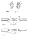
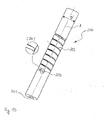
- FIGS. 1a and 1b a spring element 1 according to a first embodiment is shown.
- the spring element 1 consists of a cylindrical tube with a continuous coaxial bore 2 and a spiral with a predetermined pitch and over a predetermined length in the direction of the cylinder axis extending in the wall recess 3, which opens into the bore 2 in the radial direction.
- a coil spring is formed.
- the length of the spiral recess in the direction of the cylinder axis, the height of the recess, the pitch of the spiral and the diameter of the coaxial bore are chosen so that a desired stiffness of the coil spring against axial forces, bending forces and Torsions adoptedn, which act on the spring element, is given.
- Adjacent to its two free ends, the spring element 1 Adjacent to its two free ends, the spring element 1 in each case over a predetermined length extending internal thread 4, 4 'on.
- the outer diameter of the spring element is chosen according to the particular application.
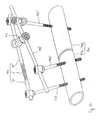
- the elastic rod-shaped element 30 consists of the spring element 1 and two cylindrical bar sections 31, 31 ', which at their end in each case a cylindrical projection 32, 32' with an external thread 33, 33rd ', which cooperates with the internal thread 4, 4' of the spring element 1.
- the rod sections and the spring element in this embodiment have substantially the same outer diameter.
- the length of the rod sections 31, 31 'and the spring element 1 are independently selectable with regard to a desired application.
- the rod-shaped element is used for example for connecting pedicle screws to the spine.
- the thus formed rod-shaped element 30 absorbs by the elastic properties of the spring element 1 to a predetermined extent compression, extension, bending and torsional forces.
- an elastic rod-shaped element 80 is shown, which differs from the elastic rod-shaped element 30 in that a first rigid rod portion 81 has a larger outer diameter than the spring element 1 and the second rigid rod portion 81 'has a smaller outer diameter than the spring element 1.
- both bar sections may have a larger or smaller diameter than the spring element.
- Fig. 3a shows a second example of application of the spring element.
- the spring element 1 is here part of a bone anchoring element 10, which is designed as a polyaxial bone screw.
- the polyaxial bone screw has a screw element 11, which consists of the spring element 1, a shaft 12 with a tip, not shown, and a screw head 13.
- the shaft 12 has a bone thread 24 for screwing into the bone and a cylindrical projection 25 with an external thread, which cooperates with the internal thread 4 of the spring element 1.
- the screw head 13 has a cylindrical portion 27 and adjoining it like the shaft 12 has a cylindrical projection 26 with an external thread, which cooperates with the internal thread 4 'of the spring element 1.
- the screw member 11 is pivotally supported in a receiving part 14 in the unloaded state.
- the receiving part 14 is formed substantially cylindrical and has at its one end an axially symmetrical aligned first bore 15 whose diameter is greater than that of the shaft 12 and smaller than that of the screw head 13. Further, the receiving part 14 has a coaxial second bore 16 which is open on the opposite end of the first bore 15 and whose diameter is so large that the screw member is guided through the open end with the shaft through the first bore 15 until the Screw head 13 abuts the edge of the first bore 15.
- the receiving part 14 has a from the free end in the direction of the first bore 15 extending U-shaped recess 14 'through which two free legs 17, 18 are formed. In a region adjacent to their free end, the legs 17, 18 on an internal thread, which with a corresponding external thread an internal screw 19 for fixing a rod 20 cooperates.
- the outer diameter of the pressure element 21 is selected so that the pressure element 21 is displaceable in the receiving part 14 to the screw head 13.
- the pressure member 21 further includes a coaxial bore 23 for accessing a recess (not shown) in the screw head 13 for engagement with a screwing tool.
- the polyaxial screw is not limited to the above-described embodiment, but may be any other polyaxial screw having a three-piece screw member as described above.
- the first bore 15 at the in Fig. 3a shown application example also be smaller in diameter than the shaft 12, when in operation first the screw head 13 is inserted with its cylindrical projection 26 ahead through the second bore 16 in the receiving part 14 before the spring element 1 and the shaft 12 screwed to the screw head 12 becomes. It is sufficient in this case if the first bore 15 has a larger diameter than the cylindrical projection 26 and as the cylindrical portion 27.
- the screw head 13 may be formed without the cylindrical portion 27. The bore then only has to be so large that the projection 26 can be passed.
- the receiving part can also be designed such that the screw member is insertable from below and is clamped by a pressure element in the receiving part.
- bore 15 is then larger than the diameter of the screw head 13th
- the rod fixation is not on the in Fig. 3a shown limited internal screw, but it may additionally be provided an outer nut, or any known type of rod fixing can be used.
- the spring element 1 protrudes at least partially over the bone surface, the spring element 1 can absorb bending forces, as well as tensile and compressive forces. If the spring element no longer protrudes beyond the bone surface, the screw element can Nevertheless, give in with a movement of the bone or vertebra something. This prevents unfavorable voltages from occurring.
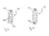
- Fig. 3b shows a development of the spring element 1 of Fig. 3a
- the spring element 640 according to Fig. 3b has a core 641 in its interior.
- the core 641 is formed at its ends 642 cylindrical with a diameter which is dimensioned so that the core is inserted into the cavity of the elastic portion 640.
- the cylindrical sections 642 and the resilient section 640 have transverse bores into which are inserted pins 64 for securing the core.
- the core has a portion 644 with a substantially rectangular cross-section, as in particular from Fig. 3c is apparent.
- the core has a different cross-section, such as oval or asymmetrical.
- the core allows the adjustment of the bending stiffness and / or the torsional rigidity of the elastic portion.
- the rigidity of the elastic portion against bending in a certain direction depends on the orientation of the core inside the elastic portion.
- the core is formed of a material having a lower rigidity compared to the material of the elastic portion. The illustrated attachment of the core is shown only by way of example.
- a stabilization device 90 for the spine wherein two bone anchoring elements 91, 91 'is used with screw elements 93 and an elastic rod-shaped element 92 each with a spring element 1 according to the invention for connecting the two bone anchoring elements. Due to the multi-part of the elastic rod-shaped element and the screw member, it is possible to obtain by the combination of only a few basic elements stabilizing devices 90 with a variety of properties.
- the stabilizing device need not necessarily include bone anchoring elements with a spring element and a rod-shaped element with the spring element. Depending on the field of application, it is also possible to provide only a rod-shaped element with spring element and bone anchoring elements with rigid screw elements.
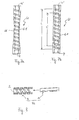
- a spring element 40 is shown according to a second embodiment.
- the spring element 40 according to the second embodiment differs from the spring element 1 according to the first embodiment only in that instead of the two internal threads 4, 4 'is provided over the entire length of the spring element formed internal thread 41.
- a spring element 50 is shown according to a third embodiment. In contrast to the first and second embodiments, it has rigid end sections 51 and 51 'or, in contrast to the previous embodiments, a reduced number of spiral turns. As a result, the elasticity of the spring element can be designed independently of the length of the spring element.
- a spring element 60 is shown according to a fourth embodiment, which has in contrast to the preceding embodiments, two by 180 ° staggered concave to the central axis formed areas 61.
- the length L 'of the regions 61 in the direction of the center axis is at most equal to the length L of the spiral and the radius of curvature of the integrally formed regions 61 is such that the turns the coil spring are not broken.
- the spring element is formed in a direction perpendicular to the center axis waisted and thus has a lower rigidity in this direction.
- the spring element has an oriented stiffness, which is useful for certain applications.
- An in Fig. 8 illustrated spring element 72 according to a fifth embodiment, in addition to the spring element 1 according to the first embodiment, a rod-shaped core 71 inserted into the bore.
- the core can serve as a stop when applied to the spring element 72 compressive forces on the one hand.
- the rigidity of the spring element 72 with respect to bending forces can be increased.
- An in Fig. 9 illustrated spring element 160 according to a sixth embodiment has at its one end, instead of a bore with an internal thread as in the first embodiment, a cylindrical projection 161 with an external thread. Accordingly, the element to be connected to this end of the spring element is formed with a bore with a corresponding internal thread. The other end of the spring element is provided with a blind bore 162 in which an internal thread 163 is formed adjacent to the end of the spring element as in the previously described embodiments.
- An in Fig. 10 illustrated spring element 170 according to a seventh embodiment has at its two ends in each case a cylindrical projection 171, 172 with an external thread.
- the spring element has no through hole.
- a connecting element 100 which consists of a rod-shaped element 31, a spring element 1 and a plate 101.
- the rod-shaped element 31 has a cylindrical projection 32 with an external thread 33 for screwing into the adjacent to the one end of the spring element 1 internal thread 4.
- the plate 101 has a cylindrical projection 102 with an external thread 103 for screwing into the adjoining the other end of the spring element 1 internal thread 4 '.
- the plate consists of two circular in plan view sections 104, 104 ', which are interconnected via a web 105. The width B of the web 105 is less than the diameter D of the circular portions 104, 104 '.
- the plate 101 Coaxial with the circular sections are provided two holes 106, 106 'for countersunk screws through the plate.
- the first side 107 of the plate has a concave curvature while the second side 108 of the plate has a convex curvature for abutment of this side to a bone. Due to the different radii of curvature of the two sides 107, 108 of the plate 101, the plate 101 tapers towards the lateral edges 109. This allows the plate to be stable and at the same time space-saving.
- 11b contiguous to the second side 108 is an opening 106a adjacent thereto, a conically shaped first portion 106b, and a second portion 106c contiguous with the first portion and the first side 107. Due to this shape of the bores 106, 106 ', these are designed to be suitable for receiving countersunk screws.
- the shape of the bores 106, 106 ' may also be of the type previously described Deviate in shape, as far as it is suitable for receiving a countersunk screw.
- Fig. 12 is an example of application for the connecting element 100 from Fig. 11a in which the plate 101 is fixed from the posterior side with two bone screws 110 to two vertebrae 111 of the cervical spine, and in which the rod-shaped element 31 connected to the plate via a spring element 1 with three bone anchoring elements 115 is anchored in vertebrae 112 of the thoracic spine.
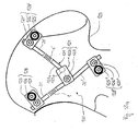
- FIG Fig. 13a Another application example, in which the spring element 1 according to the invention is used in a dynamic pelvic stabilization device 130, is shown in FIG Fig. 13a shown.
- the dynamic pelvic stabilization device consists of bone anchoring elements 128, 128 ', 128 ", which are connected to each other with rod-shaped elements 31, 31', 31" and spring elements 1, 1 '.
- Bone anchoring element 128, like the two other bone anchoring elements 128 ', 128 ", consists of two halves 125, 131, which are screwed together with a screw 127 engaging in a thread 134 in the first half 125 and in a thread 135 in the second half 131.
- the rod-shaped element 31 is clamped in a recess 132 in the first half 125 and in a recess 133 in the second half 131 between the two halves, so that the bone anchoring element 128 fixed to the rod-shaped Element 31 is connected.
- the bone screw 126 has a shaft-shaped portion 151 with an external thread 152 for screwing into the bone and a spherical segment-shaped head portion 153 with a radius which is substantially equal to the radius of the spherical recesses 138, 139.
- the connecting element 124 like the bone anchoring element, consists of two halves 122, of which in plan view Fig. 13a only one can be seen. Between these two halves 122 mentioned above, the rod-shaped element 31 is clamped in a recess, so that the connecting element 124 is firmly connected to the rod-shaped element 31.
- the rod member 121 consists of a spherical head portion 121b and a shaft portion 121a.
- the head portion 121b is clamped between the two halves 122 in a recess, not shown, and is fixed in a specific pivot position with the two halves 122 connected.
- the shaft section 121a has a cylindrical projection (not shown) with an external thread, which is screwed into the internal thread (not shown) of the spring element 1 '.
- Fig. 14 is another application example of the spring element 1 according to the invention shown.
- the spring element 1 is here part of an external fixator for stabilizing a bone 141 consisting of two parts 141a and 141b.
- the first Schanz screw 143 and the second Schanz screw 143' are in in a known manner via a first rod 145 and a second rod 145 'with the third Schanz screw 143 "connected.
- the first and the second rod 145, 145 ' are additionally firmly connected to one another in a manner known per se with a coupling element 146 which is not described here in detail.
- the first rod 145 is in three parts of two as above with respect to Fig. 2 described rod-shaped elements 31, 31 'and a spring element 1 according to the invention.
- the first rod-shaped element is fixedly connected to one end of the spring element 1 and the second rod-shaped element via a screw connection with the other end of the spring element 1 via a screw connection.
- a Schanz screw of the external fixator can also have such a spring element as part of its shank.
- the spring element As further examples of applications for the spring element are, for example, the use in a bone screw having only a shaft with a bone thread and a tip and a head, as they are commonly used for connection with stabilizing plates. Another example of application of the spring element is the use in a monoaxial bone screw for connection to a rod.
- a spring element 1 by means of milling, one proceeds from a cylinder having a predetermined outer diameter made of a biocompatible material, such as titanium, and mills with a thin disc milling cutter along a spiral, the main axis of which is collinear with the main axis of the cylinder a bore 2 is formed along the main axis of the cylinder over the entire length of the cylinder such that the spiral-shaped recess 3 opens into the bore 2.
- the outlet of the spiral at the transition between the spiral section and the end-side portion of the spring element is of utmost importance.
- the spring element 200 is produced from the cylindrical body by wire eroding, laser machining or water jet machining.
- a bore 201 along the major axis A over the entire length of the cylinder body is formed.
- the wall is cut along a spiral 202 according to the wall thickness of the hollow cylinder by one of the above-mentioned methods.
- the outlet 203 of the spiral 202 is formed as a quarter circle, so that a post-processing of the outlet 203 is omitted in a further step compared to the milling.
- the shape of the spout does not necessarily have the shape of a quarter-circle, but may also have any other arbitrary shape, such as those of another circular section, are kept low by the load peaks in the material during operation.
- a cylindrical projection with an external thread is formed by turning.
- the diameter of the bore must be smaller than the diameter of the cylindrical extension.
- the spring element according to the sixth and seventh embodiment is produced without a through bore.
- the core or the elements connected thereto are body-friendly materials, such as e.g. a body-friendly metal, such as titanium or a body-friendly plastic possible. Also, the use of a shape memory alloy with known superelastic properties, e.g. Nitinol, is possible.
Abstract
Description
Die Erfindung betrifft ein Federelement für die Verwendung in der Wirbelsäulen- oder Unfallchirurgie, ein Knochenverankerungselement mit einem solchen Federelement, ein elastisches stabförmiges Element mit einem solchen Federelement zum Verbinden von Knochenverankerungselementen und ein Herstellungsverfahren für ein solches Federelement.The invention relates to a spring element for use in spinal or trauma surgery, a bone anchoring element with such a spring element, an elastic rod-shaped element with such a spring element for connecting bone anchoring elements and a manufacturing method for such a spring element.
Zur Fixierung von Knochenfrakturen oder zur Stabilisierung der Wirbelsäule sind Fixations- und Stabilisierungseinrichtungen bekannt, die aus wenigstens zwei im Knochen bzw. Wirbel verankerten und über eine Platte oder über einem Stab verbundenen Knochenschrauben bestehen. Derartige starre Systeme erlauben keine Bewegung der relativ zu einander fixierten Knochenteile oder Wirbel.For fixation of bone fractures or for stabilization of the spine fixation and stabilization devices are known, which consist of at least two anchored in the bone or vertebrae and connected via a plate or a rod bone screws. Such rigid systems do not allow movement of the relative to each other fixed bone parts or vertebrae.
Für bestimmte Indikationen ist jedoch eine dynamische Stabilisierung wünschenswert, bei der die zu stabilisierenden Knochenteile und Wirbel eine kontrollierte begrenzte Bewegung zu einander ausführen können. Eine Möglichkeit für die Realisierung der dynamischen Stabilisierungseinrichtung besteht in der Verwendung eines elastischen Elementes anstelle eines die Knochenverankerungselemente verbindenden starren Stabes.However, for certain indications dynamic stabilization is desirable in which the bone parts and vertebrae to be stabilized can perform a controlled limited movement towards each other. One possibility for the realization of the dynamic stabilization device is the use of an elastic element instead of a rigid rod connecting the bone anchoring elements.
Aus der
Aus der
Aus der
Es ist Aufgabe der Erfindung, ein Federelement bereit zu stellen, das einfach und kompakt gebaut, sowie leicht zu handhaben bei gleichzeitig hoher Sicherheit im Einsatz ist, und welches mit anderen Elementen in möglichst vielfältiger Weise zu einer dynamischen Stabilisierungseinrichtung für miteinander zu verbindende Wirbel oder Knochen kombiniert werden kann. Ferner ist es Aufgabe der Erfindung, ein Herstellungsverfahren für das Federelement bereit zu stellen.It is an object of the invention to provide a spring element that is simple and compact, and easy to use with high security in use, and which with other elements in as many ways as possible to a dynamic stabilization device for vertebrae or bones to be joined together can be combined. It is another object of the invention to provide a manufacturing method for the spring element.
Die Aufgabe wird gelöst durch ein Federelement nach dem Patentanspruch 1.The object is achieved by a spring element according to
Weiterbildungen der Erfindung sind in den Unteransprüchen angegeben.Further developments of the invention are specified in the subclaims.
Die Erfindung weist den Vorteil auf, daß ein Federelement wahlweise mit starren stabförmigen Elementen verschiedener Länge zu einem elastischen stabförmigen Element kombinierbar ist oder mit verschiedenen Schäften und/oder Köpfen zu einer Knochenschraube mit elastischen Eigenschaften kombinierbar ist. Der Federstab bzw. die Knochenschraube weisen dann in Abhängigkeit von dem verwendetem Federelement vorgegebene elastische Eigenschaften wie eine bestimmte Kompressions- und Extensionsfähigkeit in axialer Richtung, sowie eine bestimmte Biege- und Torsionssteifigkeit auf.The invention has the advantage that a spring element can optionally be combined with rigid rod-shaped elements of different lengths to form an elastic rod-shaped element or combined with different shafts and / or heads to form a bone screw with elastic properties. The spring rod or the bone screw then have depending on the spring element used predetermined elastic properties such as a certain compression and extensibility in the axial direction, and a certain bending and torsional stiffness.
Insbesondere kann das Federelement mit stabförmigen Bauteilen verschiedener Dicke oder mit in der Wirbelsäulen- und/oder Unfallchirurgie zu verwendenden Platten unterschiedlicher Form und Länge verbunden werden.In particular, the spring element can be connected to rod-shaped components of different thickness or to be used in spinal and / or trauma surgery plates of different shape and length.
Weitere Merkmale und Zweckmäßigkeiten ergeben sich aus der Beschreibung von Ausführungsbeispielen anhand der Figuren.Further features and expediencies will become apparent from the description of embodiments with reference to FIGS.
Von den Figuren zeigen:
- Fig. 1a
- eine Seitenansicht einer ersten Ausführungsform des Federelementes;
- Fig. 1b
- eine Schnittdarstellung des Federelementes aus
Fig. 1a ; - Fig. 2a
- ein erstes Anwendungsbeispiel des Federelements in Form eines stabförmigen Elements;
- Fig. 2b
- eine Abwandlung von
Fig. 2a ; - Fig. 3a
- ein Knochenverankerungselement mit dem Federelement aus
Fig. 1a ; - Fig. 3b
- eine Schnittdarstellung eines Teils der Ausführungs- form von
Fig. 3a mit einer Weiterbildung; - Fig. 3c
- eine Schnittdarstellung des Teils von
Fig. 3b entlang der Linie A-A; - Fig. 4
- eine Stabilisierungseinrichtung bestehend aus zwei dreiteiligen Knochenverankerungselementen und einem stabförmigen Element, die jeweils ein Federelement aufweisen;
- Fig. 5
- eine Seitenansicht einer zweiten Ausführungsform des Federelementes;
- Fig. 6
- eine Seitenansicht einer dritten Ausführungsform des Federelementes;
- Fig. 7a
- eine Seitenansicht eines Federelementes nach einer vierten Ausführungsform;
- Fig. 7b
- eine um 90° gedrehte Seitenansicht des Federelementes aus
Fig. 4a ; - Fig. 8
- eine Schnittdarstellung eines Federelementes nach ei- ner fünften Ausführungsform;
- Fig. 9
- ein Federelement nach einer sechsten Ausführungsform der Erfindung;
- Fig. 10
- ein Federelement nach einer siebten Ausführungsform der Erfindung;
- Fig. 11a
- eine Explosionsdarstellung eines Verbindungselementes, das aus einem stabförmigen Element, einem erfindungs- gemäßen Federelement und einer Platte besteht;
- Fig. 11b
- eine Schnittdarstellung der Platte aus
Fig. 11a ent- lang der Linie A-A; - Fig. 12
- ein Anwendungsbeispiel der Platte aus
Fig. 11a und 11b , bei dem die Platte und das mit der Platte über ein Federelement verbundene stabförmige Element mit Knochenverankerungselementen jeweils in Wirbeln veran- kert ist; - Fig. 13a
- eine Anwendung des erfindungsgemäßen Federelementes in einer dynamischen Stabilisierungseinrichtung für einen Beckenknochen;
- Fig. 13b
- eine Schnittdarstellung eines bei der Stabilisierungs- einrichtung aus
Fig. 13a verwendeten Knochenveranke- rungselementes; - Fig. 14
- eine Anwendung des Federelementes in einem Fixateur Externe mit Schanzschrauben, die über stabförmige Ele- mente miteinander verbunden sind; und
- Fig. 15
- ein mittels Drahterodieren, Laserbearbeitung oder Was- serstrahlbearbeitung hergestelltes erfindungsgemäßes Federelement.
- Fig. 1a
- a side view of a first embodiment of the spring element;
- Fig. 1b
- a sectional view of the spring element
Fig. 1a ; - Fig. 2a
- a first example of application of the spring element in the form of a rod-shaped element;
- Fig. 2b
- a modification of
Fig. 2a ; - Fig. 3a
- a bone anchoring element with the spring element
Fig. 1a ; - Fig. 3b
- a sectional view of part of the embodiment of
Fig. 3a with a further education; - Fig. 3c
- a sectional view of the part of
Fig. 3b along the line AA; - Fig. 4
- a stabilizing device consisting of two three-part bone anchoring elements and a rod-shaped element, each having a spring element;
- Fig. 5
- a side view of a second embodiment of the spring element;
- Fig. 6
- a side view of a third embodiment of the spring element;
- Fig. 7a
- a side view of a spring element according to a fourth embodiment;
- Fig. 7b
- a rotated by 90 ° side view of the spring element
Fig. 4a ; - Fig. 8
- a sectional view of a spring element according to a fifth embodiment;
- Fig. 9
- a spring element according to a sixth embodiment of the invention;
- Fig. 10
- a spring element according to a seventh embodiment of the invention;
- Fig. 11a
- an exploded view of a connecting element, which consists of a rod-shaped element, a spring element according to the invention and a plate;
- Fig. 11b
- a sectional view of the plate
Fig. 11a along the line AA; - Fig. 12
- an example of application of the plate
Fig. 11a and 11b in which the plate and the one with the plate over a spring-element-connected rod-shaped element with bone anchoring elements is anchored in vertebrae in each case; - Fig. 13a
- an application of the spring element according to the invention in a dynamic stabilization device for a pelvic bone;
- Fig. 13b
- a sectional view of one in the stabilization device from
Fig. 13a used bone anchoring element; - Fig. 14
- an application of the spring element in a fixator external with Schanz screws, which are connected to each other via rod-shaped elements; and
- Fig. 15
- an inventive spring element produced by means of wire EDM, laser processing or water jet machining.
In den
Das Federelement 1 besteht aus einem zylindrischen Rohr mit einer durchgehenden koaxialen Bohrung 2 und einer spiralförmig mit einer vorbestimmten Steigung und über eine vorbestimmte Länge in Richtung der Zylinderachse in der Wandung verlaufenden Ausnehmung 3, die in radialer Richtung in die Bohrung 2 mündet. Dadurch ist eine Schraubenfeder gebildet. Die Länge der spiralförmigen Ausnehmung in Richtung der Zylinderachse, die Höhe der Ausnehmung, die Steigung der Spirale und der Durchmesser der koaxialen Bohrung sind so gewählt, daß eine gewünschte Steifigkeit der Schraubenfeder gegenüber axialen Kräften, Biegekräften und Torsionskräften, die auf das Federelement wirken, gegeben ist. Angrenzend an seine beiden freien Enden weist das Federelement 1 jeweils ein sich über eine vorbestimmte Länge erstreckendes Innengewinde 4, 4' auf. Der Außendurchmesser des Federelementes ist der jeweiligen Anwendung entsprechend gewählt.The
In einem ersten, in
In
Der Schaft 12 weist ein Knochengewinde 24 zum Einschrauben in den Knochen und einen zylinderförmigen Ansatz 25 mit einem Außengewinde auf, das mit dem Innengewinde 4 des Federelementes 1 zusammenwirkt.The
Der Schraubenkopf 13 weist einen zylinderförmigen Abschnitt 27 und daran angrenzend wie der Schaft 12 einen zylinderförmigen Ansatz 26 mit einem Außengewinde auf, das mit dem Innengewinde 4' des Federelementes 1 zusammenwirkt.The
Das Schraubenelement 11 ist in einen Aufnahmeteil 14 in unbelastetem Zustand schwenkbar gehalten. Das Aufnahmeteil 14 ist im wesentlichen zylindrisch ausgebildet und weist an seinem einen Ende eine axialsymmetrisch ausgerichtete erste Bohrung 15 auf, deren Durchmesser größer als der des Schafts 12 und kleiner als der des Schraubenkopfs 13 ist. Ferner weist das Aufnahmeteil 14 eine koaxiale zweite Bohrung 16 auf, die auf dem der ersten Bohrung 15 gegenüberliegenden Ende offen ist und deren Durchmesser so groß ist, daß das Schraubenelement durch das offene Ende mit dem Schaft durch die erste Bohrung 15 hindurchführbar ist, bis der Schraubenkopf 13 am Rand der ersten Bohrung 15 anliegt. Das Aufnahmeteil 14 weist eine sich vom freien Ende in Richtung der ersten Bohrung 15 erstreckende U-förmige Ausnehmung 14' auf, durch die zwei freie Schenkel 17, 18 gebildet sind. In einem Bereich angrenzend an ihr freies Ende weisen die Schenkel 17, 18 ein Innengewinde auf, welches mit einem entsprechenden Außengewinde einer Innenschraube 19 zum Fixieren eines Stabs 20 zusammenwirkt.The
Es ist ferner ein Druckelement 21 zum Fixieren des Schraubenkopfs 13 in dem Aufnahmeteil 14 vorgesehen, das so ausgebildet ist, daß es an seiner dem Schraubenkopf 13 zugewandten Seite eine sphärische Ausnehmung 22 aufweist, deren Radius im wesentlichen gleich dem Radius des kugelsegmentförmigen Abschnitts des Schraubenkopfes 13 ist. Der Außendurchmesser des Druckelements 21 ist so gewählt, daß das Druckelement 21 in dem Aufnahmeteil 14 zu dem Schraubenkopf 13 hin verschiebbar ist. Das Druckelement 21 weist ferner eine koaxiale Bohrung 23 für den Zugriff auf eine nicht dargestellte Ausnehmung in dem Schraubenkopf 13 zum Ineingriffbringen mit einem Einschraubwerkzeug auf.There is further provided a
Im Betrieb wird in das Innengewinde 4 des Federelementes 1 der Schaft 12 mit seinem zylinderförmigen Ansatz 25 und in das Innengewinde 4' der Schraubenkopf 13 mit seinem zylinderförmigen Ansatz 26 eingeschraubt, um ein Schraubenelement 11 zu bilden. Danach wird das so gebildete Schraubenelement 11 mit dem Schaft 12 voran durch die zweite Öffnung in das Aufnahmeteil 14 eingeführt, bis der Schraubenkopf 13 am Rand der ersten Bohrung 15 anliegt. Anschließend wird das Druckelement 21 mit der sphärischen Ausnehmung voran durch die zweite Öffnung 16 in das Aufnahmeteil 14 eingeführt. Dann wird das Schraubenelement 11 in den Knochen bzw. Wirbel eingeschraubt. Schließlich wird der Stab 20 in das Aufnahmeteil 14 zwischen die beiden Schenkel 17 und 18 eingelegt, die Winkelstellung des Aufnahmeteils relativ zu dem Schraubenelement justiert und mit der Innenschraube 19 fixiert. Durch den elastischen Abschnitt werden Bewegungen um die Ruhelage in begrenzter Weise ermöglicht.In operation, in the
Die Polyaxialschraube ist nicht auf die zuvor beschriebene Ausführungsform beschränkt, sondern kann auch jede beliebige andere Polyaxialschraube mit einem wie oben beschriebenen dreiteiligen Schraubenelement sein. So kann die erste Bohrung 15 bei dem in
Das Aufnahmeteil kann aber auch derart gestaltet sein, dass das Schraubenelement von unten einführbar ist und über ein Druckelement im Aufnahmeteil verklemmt wird. Die in
Die Stabfixierung ist nicht auf die in
Wenn das Federelement 1 wenigstens teilweise über die Knochenoberfläche hervorsteht kann das Federelement 1 Biegekräfte, sowie Zug- und Druckkräfte aufnehmen. Steht das Federelement nicht mehr über die Knochenoberfläche hervor, kann das Schraubenelement 11 trotzdem bei einer Bewegung des Knochens bzw. Wirbels etwas nachgeben. Damit wird verhindert, dass ungünstige Spannungen auftreten.If the
In
In
In
In den
Ein in
Ein in
Ein in
In einer Abwandlung der ersten bis fünften Ausführungsform weist das Federelement keine durchgehende Bohrung auf.In a modification of the first to fifth embodiments, the spring element has no through hole.
Als weiteres Anwendungsbeispiel für das erfindungsgemäße Federelement 1 ist in
In
Ein weiteres Anwendungsbeispiel, bei dem das erfindungsgemäße Federelement 1 in einer dynamischen Beckenstabilisierungsseinrichtung 130 verwendet wird, ist in
Das in
Das Verbindungselement 124 besteht wie das Knochenverankerungselement aus zwei Hälften 122, von denen in der Draufsicht nach
Das Stabelement 121 besteht aus einem kugelförmigen Kopfabschnitt 121b und einem Schaftabschnitt 121a. Der Kopfabschnitt 121b wird zwischen den beiden Hälften 122 in einer nicht dargestellten Ausnehmung festgeklemmt und ist so in einer bestimmten Schwenkstellung fixierbar mit den beiden Hälften 122 verbunden. An seinem dem Kopfabschnitt 121b gegenüberliegenden Ende weist der Schaftabschnitt 121a einen zylinderförmigen Ansatz (nicht dargestellt) mit einem Außengewinde auf, das in das Innengewinde (nicht dargestellt) des Federelementes 1' eingeschraubt ist.The
In
In das erste Teil 141a des Knochens 141 sind eine erste und eine zweite Schanzschraube 143, 143' und in den zweiten Teil des Knochens 141b des Knochens 141 ist eine dritte Schanzschraube 143" eingeschraubt. Die erste Schanzschraube 143 und die zweite Schanzschraube 143' sind in an sich bekannter Art und Weise über einen ersten Stab 145 bzw. einen zweiten Stab 145' mit der dritten Schanzschraube 143" verbunden. Der erste und der zweite Stab 145, 145' sind zusätzlich mit einem hier nicht näher beschriebenen Kopplungselement 146 in an sich bekannter Art und Weise fest miteinander verbunden.In the
Der erste Stab 145 ist dreiteilig aus zwei wie weiter oben mit Bezug auf
Durch die dynamische Stabilisierung des Knochens 141 werden kleinere Bewegungen der beiden Knochenenteile 141a und 141b untereinander erlaubt. Diese kleineren Bewegungen führen zu einer wünschenswerten Stimulation für das Zusammenwachsen der beiden Knochenteile 141a, 141b.Due to the dynamic stabilization of the
Je nach Anwendungsgebiet kann auch eine Schanzschraube des Fixateur Externe ein derartiges Federelement als Teil seines Schaftes aufweisen.Depending on the field of application, a Schanz screw of the external fixator can also have such a spring element as part of its shank.
Als weitere Anwendungsbeispiele für das Federelement sind zum Beispiel der Einsatz in einer Knochenschraube, die nur einen Schaft mit einem Knochengewinde und eine Spitze sowie einem Kopf aufweist, wie sie üblicherweise zur Verbindung mit Stabilisierungsplatten verwendet werden. Ein weiteres Anwendungsbeispiel des Federelements ist der Einsatz in einer Monoaxial-Knochenschraube zum Verbinden mit einem Stab.As further examples of applications for the spring element are, for example, the use in a bone screw having only a shaft with a bone thread and a tip and a head, as they are commonly used for connection with stabilizing plates. Another example of application of the spring element is the use in a monoaxial bone screw for connection to a rod.
Zur Herstellung eines Federelementes 1 mittels Fräsen geht man von einem Zylinder mit einem vorbestimmten Aussendurchmesser aus einem biokompatiblen Material, wie z.B. Titan, aus und fräst mit einem dünnen Scheibenfräser entlang einer Spirale, deren Hauptachse kollinear zu der Hauptachse des Zylinders ist eine Ausnehmung 3. Anschließend wird entlang der Hauptachse des Zylinders über die gesamte Länge des Zylinders eine Bohrung 2 derart gebildet, dass die spiralförmige Ausnehmung 3 in die Bohrung 2 mündet. Für die Stabilität des Federelementes 1 ist der Auslauf der Spirale am Übergang zwischen dem Spiralabschnittes und dem endseitigen Abschnitt des Federelementes von größter Bedeutung. Daher ist es notwendig, mit einem Fingerfräser den Auslauf der Spirale an beiden Enden der Spirale derart nachzubearbeiten, dass die scharfe Kante an der Innenseite der Bohrung entfernt wird. Dazu wird der Auslauf mit einem Fingerfräser in einem Winkel tangential zur Spiralkontur gefräst. Im Anschluß daran wird das Bauteil innen und außen entgratet. Schließlich wird in den zwei Endabschnitten der Bohrung 2 jeweils ein Innengewinde 4, 4' gebildet.To produce a
Alternativ zum Fräsen wird das Federelement 200 mit Drahterodieren, Laserbearbeitung oder Wasserstrahlbearbeitung aus dem zylinderförmigen Körper hergestellt. Hierbei wird wie in
Schließlich wird wie bei dem Herstellungsverfahren mittels Fräsen in den zwei Endabschnitten der Bohrung 2 jeweils ein Innengewinde 4, 4' gebildet.Finally, as in the manufacturing process by means of milling in the two end portions of the
In einer Abwandlung wird bei den obigen Verfahren anstelle zumindest eines der Innengewindes 4, 4' zu Beginn des Verfahrens durch Drehen ein zylinderförmiger Ansatz mit einem Aussengewinde gebildet. In diesem Fall muß der Durchmesser der Bohrung kleiner als der Durchmesser des zylinderförmigen Ansatzes sein.In a modification, in the above methods, instead of at least one of the
In einer weiteren Abwandlung des Herstellungsverfahrens wird das Federelement entsprechend der sechsten und siebten Ausführungsform ohne eine durchgehende Bohrung hergestellt.In a further modification of the manufacturing method, the spring element according to the sixth and seventh embodiment is produced without a through bore.
Als Materialien für das Federelement, den Kern oder der damit verbundenen Elemente sind körperfreundliche Materialien, wie z.B. ein körperfreundliches Metall, wie Titan oder ein körperfreundlicher Kunststoff möglich. Auch die Verwendung einer Formgedächtnislegierung mit bekannten superelastischen Eigenschaften, z.B. Nitinol, ist möglich.As materials for the spring element, the core or the elements connected thereto are body-friendly materials, such as e.g. a body-friendly metal, such as titanium or a body-friendly plastic possible. Also, the use of a shape memory alloy with known superelastic properties, e.g. Nitinol, is possible.
Claims (8)
welches als ein rohrförmiger, im wesentlichen zylindrischer Körper mit einer spiralförmigen Ausnehmung (202) in seiner Wandung entlang seiner Hauptachse (A) mit einem ersten Ende und einem diesem gegenüberliegenden zweiten Ende und einer sich von dem ersten zum zweiten Ende erstreckenden koaxialen Bohrung (201) ausgebildet ist, wobei die Ausnehmung (202) in radialer Richtung in die Bohrung (201) des Körpers mündet, der an seinen gegenüberliegenden Enden jeweils entweder ein Innengewinde (4, 4', 41, 163) oder einen zylindrischen Ansatz mit einem Außengewinde (161, 171, 172) zum Verbinden mit einem Schaft und/oder einem Kopf einer Knochenschraube oder zum Verbinden mit einem Stababschnitt oder einer Platte aufweist, wobei
wobei das elastische Element zwei um 180° gegeneinander versetzte, konkav zur Mittenachse hin angeformte Bereiche (61) aufweist.Elastic element (200) for use in a bone or vertebra stabilizing device (130),
which is a tubular, substantially cylindrical body having a helical recess (202) in its wall along its major axis (A), having a first end and a second end opposite thereto and a coaxial bore (201) extending from the first to the second end. is formed, wherein the recess (202) opens in the radial direction in the bore (201) of the body, at its opposite ends either an internal thread (4, 4 ', 41, 163) or a cylindrical extension with an external thread (161 , 171, 172) for connecting to a shaft and / or a head of a bone screw or for connecting to a rod portion or a plate, wherein
wherein the elastic element has two offset by 180 ° from each other, concave molded to the center axis regions (61).
Applications Claiming Priority (6)
| Application Number | Priority Date | Filing Date | Title |
|---|---|---|---|
| US51846903P | 2003-11-07 | 2003-11-07 | |
| DE2003151978 DE10351978A1 (en) | 2003-11-07 | 2003-11-07 | Bone fixing unit e.g. bone screw, for stabilizing device, has shaft provided with elastic sections, and head formed to connect rod with unit that receives axial force due to elastic sections toward shaft axis and bending and torsion forces |
| US52394603P | 2003-11-21 | 2003-11-21 | |
| US55018204P | 2004-03-03 | 2004-03-03 | |
| EP09167193A EP2123230B1 (en) | 2003-11-07 | 2004-11-06 | Spring element for a stabiliser device for bones and method for producing same |
| EP04797689A EP1696809B1 (en) | 2003-11-07 | 2004-11-06 | Spring element for a bone stabilizing device |
Related Parent Applications (4)
| Application Number | Title | Priority Date | Filing Date |
|---|---|---|---|
| EP04797689A Division EP1696809B1 (en) | 2003-11-07 | 2004-11-06 | Spring element for a bone stabilizing device |
| EP04797689.9 Division | 2004-11-06 | ||
| EP09167193A Division EP2123230B1 (en) | 2003-11-07 | 2004-11-06 | Spring element for a stabiliser device for bones and method for producing same |
| EP09167193.3 Division | 2009-08-04 |
Publications (3)
| Publication Number | Publication Date |
|---|---|
| EP2263583A2 true EP2263583A2 (en) | 2010-12-22 |
| EP2263583A3 EP2263583A3 (en) | 2011-01-19 |
| EP2263583B1 EP2263583B1 (en) | 2012-10-24 |
Family
ID=34577719
Family Applications (6)
| Application Number | Title | Priority Date | Filing Date |
|---|---|---|---|
| EP04797690A Not-in-force EP1684652B1 (en) | 2003-11-07 | 2004-11-06 | Bone fixing element and stabilising device comprising one such bone fixing element |
| EP09167193A Not-in-force EP2123230B1 (en) | 2003-11-07 | 2004-11-06 | Spring element for a stabiliser device for bones and method for producing same |
| EP07012005A Not-in-force EP1832241B1 (en) | 2003-11-07 | 2004-11-06 | Stabilising device for bones with a bone anchoring element |
| EP04797689A Not-in-force EP1696809B1 (en) | 2003-11-07 | 2004-11-06 | Spring element for a bone stabilizing device |
| EP10012835A Not-in-force EP2263583B1 (en) | 2003-11-07 | 2004-11-06 | Spring element for a bone stabilisation device |
| EP08003789A Not-in-force EP1925264B1 (en) | 2003-11-07 | 2004-11-06 | Bone anchoring element |
Family Applications Before (4)
| Application Number | Title | Priority Date | Filing Date |
|---|---|---|---|
| EP04797690A Not-in-force EP1684652B1 (en) | 2003-11-07 | 2004-11-06 | Bone fixing element and stabilising device comprising one such bone fixing element |
| EP09167193A Not-in-force EP2123230B1 (en) | 2003-11-07 | 2004-11-06 | Spring element for a stabiliser device for bones and method for producing same |
| EP07012005A Not-in-force EP1832241B1 (en) | 2003-11-07 | 2004-11-06 | Stabilising device for bones with a bone anchoring element |
| EP04797689A Not-in-force EP1696809B1 (en) | 2003-11-07 | 2004-11-06 | Spring element for a bone stabilizing device |
Family Applications After (1)
| Application Number | Title | Priority Date | Filing Date |
|---|---|---|---|
| EP08003789A Not-in-force EP1925264B1 (en) | 2003-11-07 | 2004-11-06 | Bone anchoring element |
Country Status (7)
| Country | Link |
|---|---|
| EP (6) | EP1684652B1 (en) |
| JP (2) | JP4936896B2 (en) |
| KR (2) | KR101181462B1 (en) |
| CN (2) | CN1897884B (en) |
| DE (4) | DE502004006687D1 (en) |
| ES (4) | ES2398201T3 (en) |
| WO (1) | WO2005044117A2 (en) |
Families Citing this family (65)
| Publication number | Priority date | Publication date | Assignee | Title |
|---|---|---|---|---|
| US7833250B2 (en) | 2004-11-10 | 2010-11-16 | Jackson Roger P | Polyaxial bone screw with helically wound capture connection |
| US8876868B2 (en) | 2002-09-06 | 2014-11-04 | Roger P. Jackson | Helical guide and advancement flange with radially loaded lip |
| US7887539B2 (en) | 2003-01-24 | 2011-02-15 | Depuy Spine, Inc. | Spinal rod approximators |
| US7377923B2 (en) | 2003-05-22 | 2008-05-27 | Alphatec Spine, Inc. | Variable angle spinal screw assembly |
| US8936623B2 (en) | 2003-06-18 | 2015-01-20 | Roger P. Jackson | Polyaxial bone screw assembly |
| US7776067B2 (en) | 2005-05-27 | 2010-08-17 | Jackson Roger P | Polyaxial bone screw with shank articulation pressure insert and method |
| US7766915B2 (en) | 2004-02-27 | 2010-08-03 | Jackson Roger P | Dynamic fixation assemblies with inner core and outer coil-like member |
| US20050065516A1 (en) | 2003-09-24 | 2005-03-24 | Tae-Ahn Jahng | Method and apparatus for flexible fixation of a spine |
| US8979900B2 (en) | 2003-09-24 | 2015-03-17 | DePuy Synthes Products, LLC | Spinal stabilization device |
| US7935134B2 (en) * | 2004-10-20 | 2011-05-03 | Exactech, Inc. | Systems and methods for stabilization of bone structures |
| US8926672B2 (en) | 2004-11-10 | 2015-01-06 | Roger P. Jackson | Splay control closure for open bone anchor |
| US8444681B2 (en) | 2009-06-15 | 2013-05-21 | Roger P. Jackson | Polyaxial bone anchor with pop-on shank, friction fit retainer and winged insert |
| US9393047B2 (en) | 2009-06-15 | 2016-07-19 | Roger P. Jackson | Polyaxial bone anchor with pop-on shank and friction fit retainer with low profile edge lock |
| US9168069B2 (en) | 2009-06-15 | 2015-10-27 | Roger P. Jackson | Polyaxial bone anchor with pop-on shank and winged insert with lower skirt for engaging a friction fit retainer |
| US7901437B2 (en) | 2007-01-26 | 2011-03-08 | Jackson Roger P | Dynamic stabilization member with molded connection |
| US7951175B2 (en) | 2005-03-04 | 2011-05-31 | Depuy Spine, Inc. | Instruments and methods for manipulating a vertebra |
| US7951172B2 (en) | 2005-03-04 | 2011-05-31 | Depuy Spine Sarl | Constrained motion bone screw assembly |
| DE602005007223D1 (en) | 2005-08-24 | 2008-07-10 | Biedermann Motech Gmbh | Rod-shaped element for use in spine or trauma surgery and stabilization device with such an element |
| US7722651B2 (en) | 2005-10-21 | 2010-05-25 | Depuy Spine, Inc. | Adjustable bone screw assembly |
| GB0521582D0 (en) | 2005-10-22 | 2005-11-30 | Depuy Int Ltd | An implant for supporting a spinal column |
| GB0600662D0 (en) | 2006-01-13 | 2006-02-22 | Depuy Int Ltd | Spinal support rod kit |
| US20070173825A1 (en) * | 2006-01-20 | 2007-07-26 | Stryker Spine | Spinal rod parallel coupler |
| US8348952B2 (en) | 2006-01-26 | 2013-01-08 | Depuy International Ltd. | System and method for cooling a spinal correction device comprising a shape memory material for corrective spinal surgery |
| US8048134B2 (en) | 2006-04-06 | 2011-11-01 | Andrew K. Palmer | Active compression to facilitate healing of bones |
| US7806913B2 (en) | 2006-08-16 | 2010-10-05 | Depuy Spine, Inc. | Modular multi-level spine stabilization system and method |
| US8127560B2 (en) * | 2007-06-01 | 2012-03-06 | Carleton Life Support Systems, Inc. | Machined spring with integral retainer for closed cycle cryogenic coolers |
| WO2009011845A1 (en) * | 2007-07-13 | 2009-01-22 | George Frey | Systems and methods for spinal stabilization |
| US10758283B2 (en) | 2016-08-11 | 2020-09-01 | Mighty Oak Medical, Inc. | Fixation devices having fenestrations and methods for using the same |
| KR101570213B1 (en) | 2007-12-17 | 2015-11-18 | 신세스 게엠바하 | Dynamic bone fixation element and method of using the same |
| US9232968B2 (en) | 2007-12-19 | 2016-01-12 | DePuy Synthes Products, Inc. | Polymeric pedicle rods and methods of manufacturing |
| US8608746B2 (en) | 2008-03-10 | 2013-12-17 | DePuy Synthes Products, LLC | Derotation instrument with reduction functionality |
| US8709015B2 (en) | 2008-03-10 | 2014-04-29 | DePuy Synthes Products, LLC | Bilateral vertebral body derotation system |
| KR100886757B1 (en) * | 2008-06-04 | 2009-03-04 | 문정일 | Face-lifting device |
| US10973556B2 (en) | 2008-06-17 | 2021-04-13 | DePuy Synthes Products, Inc. | Adjustable implant assembly |
| US8137384B2 (en) | 2008-09-02 | 2012-03-20 | Bhdl Holdings, Llc | Modular pedicle screw system |
| US9339320B2 (en) | 2008-09-02 | 2016-05-17 | Bhdl Holdings, Llc | Modular pedicle screw system with tap and screw driver device |
| EP2373236B1 (en) | 2008-12-17 | 2014-05-21 | Synthes GmbH | Posterior spine dynamic stabilizer |
| US8641734B2 (en) | 2009-02-13 | 2014-02-04 | DePuy Synthes Products, LLC | Dual spring posterior dynamic stabilization device with elongation limiting elastomers |
| US20100217319A1 (en) | 2009-02-24 | 2010-08-26 | Abbott Spine Inc. | System and method for spinal stabilization |
| US8480704B2 (en) | 2009-02-26 | 2013-07-09 | Bhdl Holdings, Llc | Surgical dilator, retractor and mounting pad |
| US9675334B2 (en) | 2009-02-26 | 2017-06-13 | Bhdl Holdings, Llc | Surgical dilator, retractor and mounting pad |
| US10413287B2 (en) | 2009-02-26 | 2019-09-17 | Bhdl Holdings, Llc | Surgical dilator, retractor and mounting pad |
| EP2410929B1 (en) | 2009-03-24 | 2019-06-26 | Stabiliz Orthopedics, LLC | Orthopedic fixation device with bioresorbable layer |
| US11229457B2 (en) | 2009-06-15 | 2022-01-25 | Roger P. Jackson | Pivotal bone anchor assembly with insert tool deployment |
| US8282636B2 (en) | 2009-08-10 | 2012-10-09 | Imds Corporation | Orthopedic external fixator and method of use |
| US9445844B2 (en) | 2010-03-24 | 2016-09-20 | DePuy Synthes Products, Inc. | Composite material posterior dynamic stabilization spring rod |
| US9339305B2 (en) | 2011-09-19 | 2016-05-17 | DePuy Synthes Products, Inc. | Snap fit rod and fastener system |
| TWI452993B (en) * | 2011-11-17 | 2014-09-21 | Metal Ind Res & Dev Ct | Bone screw, method for manufacturing the bone screw, and tool for mounting and removing the bone screw |
| US9339316B2 (en) | 2012-03-13 | 2016-05-17 | DePuy Synthes Products, Inc. | Dynamic bone fixation element |
| US8940020B2 (en) | 2012-04-06 | 2015-01-27 | DePuy Synthes Products, LLC | Rod connector |
| US8911478B2 (en) | 2012-11-21 | 2014-12-16 | Roger P. Jackson | Splay control closure for open bone anchor |
| EP2749239B1 (en) * | 2012-12-27 | 2016-12-07 | Biedermann Technologies GmbH & Co. KG | Dynamic bone anchor |
| US10058354B2 (en) | 2013-01-28 | 2018-08-28 | Roger P. Jackson | Pivotal bone anchor assembly with frictional shank head seating surfaces |
| US8852239B2 (en) | 2013-02-15 | 2014-10-07 | Roger P Jackson | Sagittal angle screw with integral shank and receiver |
| US9566092B2 (en) | 2013-10-29 | 2017-02-14 | Roger P. Jackson | Cervical bone anchor with collet retainer and outer locking sleeve |
| US9717533B2 (en) | 2013-12-12 | 2017-08-01 | Roger P. Jackson | Bone anchor closure pivot-splay control flange form guide and advancement structure |
| US9451993B2 (en) | 2014-01-09 | 2016-09-27 | Roger P. Jackson | Bi-radial pop-on cervical bone anchor |
| US9597119B2 (en) | 2014-06-04 | 2017-03-21 | Roger P. Jackson | Polyaxial bone anchor with polymer sleeve |
| US10064658B2 (en) | 2014-06-04 | 2018-09-04 | Roger P. Jackson | Polyaxial bone anchor with insert guides |
| CN106214236B (en) * | 2014-10-24 | 2018-11-09 | 吴昊 | A kind of ring spring shape exter-nal fixer for realizing Minimally Invasive Surgery purpose |
| US10743890B2 (en) | 2016-08-11 | 2020-08-18 | Mighty Oak Medical, Inc. | Drill apparatus and surgical fixation devices and methods for using the same |
| WO2018039485A1 (en) | 2016-08-24 | 2018-03-01 | Integrity Implants, Inc. | Adjustable bone fixation systems |
| CN108186095B (en) * | 2018-02-23 | 2020-10-27 | 何伟义 | Improvement of externally-arranged spring type ball stud capable of reducing notch |
| EP3781056A4 (en) * | 2018-06-26 | 2022-01-26 | Integrity Implants Inc. | Length adjustable modular screw system |
| CN110141344A (en) * | 2019-06-08 | 2019-08-20 | 何静 | A kind of flexible constraint formula pedicle nail of anti-explosion filaments |
Citations (3)
| Publication number | Priority date | Publication date | Assignee | Title |
|---|---|---|---|---|
| EP0669109B1 (en) | 1994-02-28 | 1999-05-26 | Sulzer Orthopädie AG | Stabilizer for adjacent vertebrae |
| US6162223A (en) | 1999-04-09 | 2000-12-19 | Smith & Nephew, Inc. | Dynamic wrist fixation apparatus for early joint motion in distal radius fractures |
| US20030109880A1 (en) | 2001-08-01 | 2003-06-12 | Showa Ika Kohgyo Co., Ltd. | Bone connector |
Family Cites Families (30)
| Publication number | Priority date | Publication date | Assignee | Title |
|---|---|---|---|---|
| JPH0616964B2 (en) * | 1984-10-08 | 1994-03-09 | 株式会社東芝 | How to make a coil |
| GB8803680D0 (en) | 1988-02-17 | 1988-03-16 | Fahmy N R M | Distraction compression spring system treatment of intra-articular fractures |
| US4959064A (en) * | 1988-10-07 | 1990-09-25 | Boehringer Mannheim Corporation | Dynamic tension bone screw |
| WO1991016020A1 (en) | 1990-04-26 | 1991-10-31 | Danninger Medical Technology, Inc. | Transpedicular screw system and method of use |
| US5423816A (en) * | 1993-07-29 | 1995-06-13 | Lin; Chih I. | Intervertebral locking device |
| FR2709246B1 (en) * | 1993-08-27 | 1995-09-29 | Martin Jean Raymond | Dynamic implanted spinal orthosis. |
| EP0677277A3 (en) * | 1994-03-18 | 1996-02-28 | Patrice Moreau | Spinal prosthetic assembly. |
| FR2717370A1 (en) * | 1994-03-18 | 1995-09-22 | Moreau Patrice | Intervertebral stabilising prosthesis for spinal reinforcement inserted during spinal surgery |
| FR2718946B1 (en) * | 1994-04-25 | 1996-09-27 | Soprane Sa | Flexible rod for lumbosacral osteosynthesis fixator. |
| US5593408A (en) * | 1994-11-30 | 1997-01-14 | Sofamor S.N.C | Vertebral instrumentation rod |
| US5662683A (en) * | 1995-08-22 | 1997-09-02 | Ortho Helix Limited | Open helical organic tissue anchor and method of facilitating healing |
| FR2751202B1 (en) * | 1996-07-22 | 2001-03-16 | Zacouto Fred | SKELETAL IMPLANT |
| JPH10122285A (en) * | 1996-10-22 | 1998-05-12 | Makino Milling Mach Co Ltd | Manufacture of cylindrical spring and cylindrical spring produced thereby |
| FR2755844B1 (en) * | 1996-11-15 | 1999-01-29 | Stryker France Sa | OSTEOSYNTHESIS SYSTEM WITH ELASTIC DEFORMATION FOR SPINE |
| DE29711559U1 (en) * | 1997-07-02 | 1997-08-21 | Howmedica Gmbh | Elongated element for the transmission of forces |
| DE29915204U1 (en) | 1999-08-26 | 1999-12-09 | Hoffmann Olaf | Spring screw |
| CN2404493Y (en) * | 1999-11-01 | 2000-11-08 | 李超 | Arch bridge type resilient pediclus arcus vertebra fixation device |
| ATE336952T1 (en) | 1999-12-01 | 2006-09-15 | Henry Graf | DEVICE FOR INTERVERBEL STABILIZATION |
| FR2812186B1 (en) * | 2000-07-25 | 2003-02-28 | Spine Next Sa | FLEXIBLE CONNECTION PIECE FOR SPINAL STABILIZATION |
| GR1003754B (en) * | 2000-09-22 | 2002-01-15 | Χρηστος Καλαιτζης | Transpedicular screw/rod/ligament system for posterior spinal arthrodesis |
| US6544265B2 (en) * | 2000-11-08 | 2003-04-08 | The Cleveland Clinic Foundation | Apparatus for implantation into bone related applications |
| US6551320B2 (en) * | 2000-11-08 | 2003-04-22 | The Cleveland Clinic Foundation | Method and apparatus for correcting spinal deformity |
| US6527774B2 (en) * | 2000-11-08 | 2003-03-04 | The Cleveland Clinic Foundation | Apparatus for attaching fractured sections of bone |
| JP3752146B2 (en) * | 2000-12-07 | 2006-03-08 | 株式会社フォーエスメディカル | External fixator |
| JP2002227898A (en) * | 2001-02-06 | 2002-08-14 | Tomoe Corp | Base isolating damper |
| DE10129490A1 (en) | 2001-06-21 | 2003-01-02 | Helmut Mueckter | Implantable screw for stabilization of joint or bone fracture, has flexible shaft which interconnects proximal head portion and distal insertion portion of elongated screw body |
| DE10132588C2 (en) * | 2001-07-05 | 2003-05-22 | Fehling Instr Gmbh | Disc prosthesis |
| CN2518470Y (en) * | 2001-07-25 | 2002-10-30 | 史亚民 | Internzl fixation device for spine fracture |
| DE10157814B4 (en) * | 2001-11-27 | 2004-12-02 | Biedermann Motech Gmbh | Closure device for securing a rod-shaped element in a holding element connected to a shaft |
| AU2002218099B2 (en) * | 2001-12-07 | 2006-04-27 | Synthes Gmbh | Damping element |
-
2004
- 2004-11-06 JP JP2006538757A patent/JP4936896B2/en not_active Expired - Fee Related
- 2004-11-06 KR KR1020067011061A patent/KR101181462B1/en not_active IP Right Cessation
- 2004-11-06 EP EP04797690A patent/EP1684652B1/en not_active Not-in-force
- 2004-11-06 EP EP09167193A patent/EP2123230B1/en not_active Not-in-force
- 2004-11-06 CN CN2004800381328A patent/CN1897884B/en not_active Expired - Fee Related
- 2004-11-06 DE DE502004006687T patent/DE502004006687D1/en active Active
- 2004-11-06 DE DE502004011567T patent/DE502004011567D1/en active Active
- 2004-11-06 CN CN200480037873A patent/CN100581493C/en not_active Expired - Fee Related
- 2004-11-06 ES ES10012835T patent/ES2398201T3/en active Active
- 2004-11-06 DE DE502004011714T patent/DE502004011714D1/en active Active
- 2004-11-06 KR KR1020067010947A patent/KR101280591B1/en not_active IP Right Cessation
- 2004-11-06 EP EP07012005A patent/EP1832241B1/en not_active Not-in-force
- 2004-11-06 ES ES04797690T patent/ES2304629T3/en active Active
- 2004-11-06 WO PCT/EP2004/012591 patent/WO2005044117A2/en active Application Filing
- 2004-11-06 EP EP04797689A patent/EP1696809B1/en not_active Not-in-force
- 2004-11-06 ES ES09167193T patent/ES2384773T3/en active Active
- 2004-11-06 JP JP2006538758A patent/JP2007510483A/en active Pending
- 2004-11-06 DE DE502004009865T patent/DE502004009865D1/en active Active
- 2004-11-06 EP EP10012835A patent/EP2263583B1/en not_active Not-in-force
- 2004-11-06 ES ES04797689T patent/ES2331247T3/en active Active
- 2004-11-06 EP EP08003789A patent/EP1925264B1/en not_active Not-in-force
Patent Citations (3)
| Publication number | Priority date | Publication date | Assignee | Title |
|---|---|---|---|---|
| EP0669109B1 (en) | 1994-02-28 | 1999-05-26 | Sulzer Orthopädie AG | Stabilizer for adjacent vertebrae |
| US6162223A (en) | 1999-04-09 | 2000-12-19 | Smith & Nephew, Inc. | Dynamic wrist fixation apparatus for early joint motion in distal radius fractures |
| US20030109880A1 (en) | 2001-08-01 | 2003-06-12 | Showa Ika Kohgyo Co., Ltd. | Bone connector |
Also Published As
Similar Documents
| Publication | Publication Date | Title |
|---|---|---|
| EP2123230B1 (en) | Spring element for a stabiliser device for bones and method for producing same | |
| EP2151207B1 (en) | Elastic element for use in a stabilising device for bones and method of fabrication of such an elastic element | |
| EP1570795B1 (en) | Apparatus for dynamic stabilisation of the spine or bones and rod-like element for same | |
| DE10348329B3 (en) | Rod-shaped element used in spinal column and accident surgery for connecting two bone-anchoring elements comprises a rigid section and an elastic section that are made in one piece | |
| EP3117787B1 (en) | Pedicle screw with tulip | |
| DE3936702C2 (en) | Pedicle screw and correction and holding device with such a pedicle screw | |
| WO2005044123A1 (en) | Bone fixing element and stabilising device comprising one such bone fixing element | |
| DE19549426C2 (en) | Intervertebral implant and instrument therefor | |
| EP1574173B1 (en) | Elastic rod-shaped element for use in spinal or accident surgery and stabilising device comprising such an element | |
| EP0570929B1 (en) | Implant for the spine | |
| EP1568329B1 (en) | Bone-anchoring element | |
| EP1830727B1 (en) | Intramedullary nail | |
| EP1450707A1 (en) | Damping element | |
| WO1990000377A1 (en) | Correction and restraining device, in particular for the vertebral column | |
| EP2848223B1 (en) | Connecting element and spinal column stabilzation system | |
| DE102004018621B4 (en) | Elastic element e.g. for stabilizing device for bones and method of fabrication of such an elastic element, has a cylindrical body with two ends and flexible section between ends and section is made from two coil springs | |
| EP1792577B1 (en) | Surgical stabilisation device with a rod-shaped element | |
| DE102007029090A1 (en) | Device for osteosynthesis, particularly bone fracture near joint, has pin for implantation into abarticular bone, and proximal longitudinal ring element provided for implantation into bone fragment near joint | |
| WO2014029032A1 (en) | Spring and device for stabilizing human or animal bones | |
| DE202008002415U1 (en) | Dynamic stabilization device | |
| DE10351978A1 (en) | Bone fixing unit e.g. bone screw, for stabilizing device, has shaft provided with elastic sections, and head formed to connect rod with unit that receives axial force due to elastic sections toward shaft axis and bending and torsion forces | |
| DE102008010358A1 (en) | Dynamic stabilization device |
Legal Events
| Date | Code | Title | Description |
|---|---|---|---|
| PUAI | Public reference made under article 153(3) epc to a published international application that has entered the european phase |
Free format text: ORIGINAL CODE: 0009012 |
|
| PUAL | Search report despatched |
Free format text: ORIGINAL CODE: 0009013 |
|
| AC | Divisional application: reference to earlier application |
Ref document number: 1696809 Country of ref document: EP Kind code of ref document: P Ref document number: 2123230 Country of ref document: EP Kind code of ref document: P |
|
| AK | Designated contracting states |
Kind code of ref document: A2 Designated state(s): CH DE ES FR GB IT LI |
|
| AK | Designated contracting states |
Kind code of ref document: A3 Designated state(s): CH DE ES FR GB IT LI |
|
| 17P | Request for examination filed |
Effective date: 20110715 |
|
| RAP1 | Party data changed (applicant data changed or rights of an application transferred) |
Owner name: BIEDERMANN TECHNOLOGIES GMBH & CO. KG |
|
| RTI1 | Title (correction) |
Free format text: SPRING ELEMENT FOR A BONE STABILISATION DEVICE |
|
| GRAP | Despatch of communication of intention to grant a patent |
Free format text: ORIGINAL CODE: EPIDOSNIGR1 |
|
| GRAS | Grant fee paid |
Free format text: ORIGINAL CODE: EPIDOSNIGR3 |
|
| GRAA | (expected) grant |
Free format text: ORIGINAL CODE: 0009210 |
|
| AC | Divisional application: reference to earlier application |
Ref document number: 2123230 Country of ref document: EP Kind code of ref document: P Ref document number: 1696809 Country of ref document: EP Kind code of ref document: P |
|
| AK | Designated contracting states |
Kind code of ref document: B1 Designated state(s): CH DE ES FR GB IT LI |
|
| REG | Reference to a national code |
Ref country code: GB Ref legal event code: FG4D Free format text: NOT ENGLISH |
|
| REG | Reference to a national code |
Ref country code: CH Ref legal event code: NV Representative=s name: NOVAGRAAF INTERNATIONAL SA Ref country code: CH Ref legal event code: EP |
|
| REG | Reference to a national code |
Ref country code: DE Ref legal event code: R096 Ref document number: 502004013847 Country of ref document: DE Effective date: 20121220 |
|
| REG | Reference to a national code |
Ref country code: ES Ref legal event code: FG2A Ref document number: 2398201 Country of ref document: ES Kind code of ref document: T3 Effective date: 20130314 |
|
| PLBE | No opposition filed within time limit |
Free format text: ORIGINAL CODE: 0009261 |
|
| STAA | Information on the status of an ep patent application or granted ep patent |
Free format text: STATUS: NO OPPOSITION FILED WITHIN TIME LIMIT |
|
| 26N | No opposition filed |
Effective date: 20130725 |
|
| REG | Reference to a national code |
Ref country code: DE Ref legal event code: R097 Ref document number: 502004013847 Country of ref document: DE Effective date: 20130725 |
|
| REG | Reference to a national code |
Ref country code: FR Ref legal event code: PLFP Year of fee payment: 12 |
|
| REG | Reference to a national code |
Ref country code: FR Ref legal event code: PLFP Year of fee payment: 13 |
|
| PGFP | Annual fee paid to national office [announced via postgrant information from national office to epo] |
Ref country code: FR Payment date: 20161124 Year of fee payment: 13 |
|
| PGFP | Annual fee paid to national office [announced via postgrant information from national office to epo] |
Ref country code: IT Payment date: 20161124 Year of fee payment: 13 Ref country code: ES Payment date: 20161124 Year of fee payment: 13 |
|
| REG | Reference to a national code |
Ref country code: FR Ref legal event code: ST Effective date: 20180731 |
|
| PG25 | Lapsed in a contracting state [announced via postgrant information from national office to epo] |
Ref country code: FR Free format text: LAPSE BECAUSE OF NON-PAYMENT OF DUE FEES Effective date: 20171130 Ref country code: IT Free format text: LAPSE BECAUSE OF NON-PAYMENT OF DUE FEES Effective date: 20171106 |
|
| PG25 | Lapsed in a contracting state [announced via postgrant information from national office to epo] |
Ref country code: ES Free format text: LAPSE BECAUSE OF NON-PAYMENT OF DUE FEES Effective date: 20171107 |
|
| PGFP | Annual fee paid to national office [announced via postgrant information from national office to epo] |
Ref country code: GB Payment date: 20211123 Year of fee payment: 18 Ref country code: DE Payment date: 20211129 Year of fee payment: 18 |
|
| PGFP | Annual fee paid to national office [announced via postgrant information from national office to epo] |
Ref country code: CH Payment date: 20211123 Year of fee payment: 18 |
|
| REG | Reference to a national code |
Ref country code: DE Ref legal event code: R119 Ref document number: 502004013847 Country of ref document: DE |
|
| REG | Reference to a national code |
Ref country code: CH Ref legal event code: PL |
|
| GBPC | Gb: european patent ceased through non-payment of renewal fee |
Effective date: 20221106 |
|
| PG25 | Lapsed in a contracting state [announced via postgrant information from national office to epo] |
Ref country code: LI Free format text: LAPSE BECAUSE OF NON-PAYMENT OF DUE FEES Effective date: 20221130 Ref country code: CH Free format text: LAPSE BECAUSE OF NON-PAYMENT OF DUE FEES Effective date: 20221130 |
|
| PG25 | Lapsed in a contracting state [announced via postgrant information from national office to epo] |
Ref country code: GB Free format text: LAPSE BECAUSE OF NON-PAYMENT OF DUE FEES Effective date: 20221106 Ref country code: DE Free format text: LAPSE BECAUSE OF NON-PAYMENT OF DUE FEES Effective date: 20230601 |