EP2264128A2 - Catalyst structure and method of fischer-tropsch synthesis - Google Patents
Catalyst structure and method of fischer-tropsch synthesis Download PDFInfo
- Publication number
- EP2264128A2 EP2264128A2 EP10012645A EP10012645A EP2264128A2 EP 2264128 A2 EP2264128 A2 EP 2264128A2 EP 10012645 A EP10012645 A EP 10012645A EP 10012645 A EP10012645 A EP 10012645A EP 2264128 A2 EP2264128 A2 EP 2264128A2
- Authority
- EP
- European Patent Office
- Prior art keywords
- catalyst
- reactor
- reaction chamber
- less
- fischer
- Prior art date
- Legal status (The legal status is an assumption and is not a legal conclusion. Google has not performed a legal analysis and makes no representation as to the accuracy of the status listed.)
- Granted
Links
- 239000003054 catalyst Substances 0.000 title claims abstract description 206
- 238000000034 method Methods 0.000 title abstract description 39
- 230000015572 biosynthetic process Effects 0.000 title description 19
- 238000003786 synthesis reaction Methods 0.000 title description 14
- 238000006243 chemical reaction Methods 0.000 claims abstract description 102
- VNWKTOKETHGBQD-UHFFFAOYSA-N methane Chemical compound C VNWKTOKETHGBQD-UHFFFAOYSA-N 0.000 claims abstract description 84
- 229910052751 metal Inorganic materials 0.000 claims abstract description 48
- 239000002184 metal Substances 0.000 claims abstract description 48
- UGFAIRIUMAVXCW-UHFFFAOYSA-N Carbon monoxide Chemical compound [O+]#[C-] UGFAIRIUMAVXCW-UHFFFAOYSA-N 0.000 claims abstract description 42
- 229910002091 carbon monoxide Inorganic materials 0.000 claims abstract description 42
- 230000003197 catalytic effect Effects 0.000 claims abstract description 27
- UFHFLCQGNIYNRP-UHFFFAOYSA-N Hydrogen Chemical compound [H][H] UFHFLCQGNIYNRP-UHFFFAOYSA-N 0.000 claims abstract description 17
- 238000010438 heat treatment Methods 0.000 claims abstract description 14
- 239000011148 porous material Substances 0.000 claims description 51
- 238000012546 transfer Methods 0.000 claims description 21
- 239000000376 reactant Substances 0.000 claims description 11
- 238000001816 cooling Methods 0.000 claims description 10
- 229910052799 carbon Inorganic materials 0.000 claims description 7
- 230000003647 oxidation Effects 0.000 claims description 6
- 238000007254 oxidation reaction Methods 0.000 claims description 6
- 238000005382 thermal cycling Methods 0.000 claims description 3
- 239000007789 gas Substances 0.000 abstract description 13
- 229910052739 hydrogen Inorganic materials 0.000 abstract description 6
- 239000001257 hydrogen Substances 0.000 abstract description 6
- GWEVSGVZZGPLCZ-UHFFFAOYSA-N Titan oxide Chemical compound O=[Ti]=O GWEVSGVZZGPLCZ-UHFFFAOYSA-N 0.000 description 30
- PNEYBMLMFCGWSK-UHFFFAOYSA-N aluminium oxide Inorganic materials [O-2].[O-2].[O-2].[Al+3].[Al+3] PNEYBMLMFCGWSK-UHFFFAOYSA-N 0.000 description 27
- 239000000047 product Substances 0.000 description 24
- 239000000843 powder Substances 0.000 description 17
- 238000000151 deposition Methods 0.000 description 15
- 239000006260 foam Substances 0.000 description 15
- 239000006262 metallic foam Substances 0.000 description 13
- 230000008569 process Effects 0.000 description 12
- 150000004706 metal oxides Chemical group 0.000 description 11
- 238000000576 coating method Methods 0.000 description 10
- 229910044991 metal oxide Inorganic materials 0.000 description 10
- XEEYBQQBJWHFJM-UHFFFAOYSA-N Iron Chemical compound [Fe] XEEYBQQBJWHFJM-UHFFFAOYSA-N 0.000 description 9
- PXHVJJICTQNCMI-UHFFFAOYSA-N Nickel Chemical compound [Ni] PXHVJJICTQNCMI-UHFFFAOYSA-N 0.000 description 9
- 239000002243 precursor Substances 0.000 description 9
- 239000002002 slurry Substances 0.000 description 9
- VYPSYNLAJGMNEJ-UHFFFAOYSA-N Silicium dioxide Chemical compound O=[Si]=O VYPSYNLAJGMNEJ-UHFFFAOYSA-N 0.000 description 8
- 230000008901 benefit Effects 0.000 description 8
- 229910052593 corundum Inorganic materials 0.000 description 8
- 238000004519 manufacturing process Methods 0.000 description 8
- 239000000203 mixture Substances 0.000 description 8
- 229910001845 yogo sapphire Inorganic materials 0.000 description 8
- 238000005229 chemical vapour deposition Methods 0.000 description 7
- 238000002474 experimental method Methods 0.000 description 7
- 229930195733 hydrocarbon Natural products 0.000 description 7
- 150000002430 hydrocarbons Chemical class 0.000 description 7
- 239000000463 material Substances 0.000 description 7
- IJGRMHOSHXDMSA-UHFFFAOYSA-N Atomic nitrogen Chemical compound N#N IJGRMHOSHXDMSA-UHFFFAOYSA-N 0.000 description 6
- 239000004215 Carbon black (E152) Substances 0.000 description 6
- KJTLSVCANCCWHF-UHFFFAOYSA-N Ruthenium Chemical compound [Ru] KJTLSVCANCCWHF-UHFFFAOYSA-N 0.000 description 6
- MCMNRKCIXSYSNV-UHFFFAOYSA-N Zirconium dioxide Chemical compound O=[Zr]=O MCMNRKCIXSYSNV-UHFFFAOYSA-N 0.000 description 6
- 239000011149 active material Substances 0.000 description 6
- 239000011248 coating agent Substances 0.000 description 6
- 229910017052 cobalt Inorganic materials 0.000 description 6
- 239000010941 cobalt Substances 0.000 description 6
- GUTLYIVDDKVIGB-UHFFFAOYSA-N cobalt atom Chemical compound [Co] GUTLYIVDDKVIGB-UHFFFAOYSA-N 0.000 description 6
- 230000008021 deposition Effects 0.000 description 6
- 239000002245 particle Substances 0.000 description 6
- 239000008188 pellet Substances 0.000 description 6
- 229910052707 ruthenium Inorganic materials 0.000 description 6
- 230000000694 effects Effects 0.000 description 5
- 230000001965 increasing effect Effects 0.000 description 5
- 229910052762 osmium Inorganic materials 0.000 description 5
- SYQBFIAQOQZEGI-UHFFFAOYSA-N osmium atom Chemical compound [Os] SYQBFIAQOQZEGI-UHFFFAOYSA-N 0.000 description 5
- 229910052702 rhenium Inorganic materials 0.000 description 5
- WUAPFZMCVAUBPE-UHFFFAOYSA-N rhenium atom Chemical compound [Re] WUAPFZMCVAUBPE-UHFFFAOYSA-N 0.000 description 5
- 229910001220 stainless steel Inorganic materials 0.000 description 5
- 239000010935 stainless steel Substances 0.000 description 5
- 239000000126 substance Substances 0.000 description 5
- UQSXHKLRYXJYBZ-UHFFFAOYSA-N Iron oxide Chemical compound [Fe]=O UQSXHKLRYXJYBZ-UHFFFAOYSA-N 0.000 description 4
- -1 Platinum Metals Chemical class 0.000 description 4
- XLOMVQKBTHCTTD-UHFFFAOYSA-N Zinc monoxide Chemical compound [Zn]=O XLOMVQKBTHCTTD-UHFFFAOYSA-N 0.000 description 4
- 239000000446 fuel Substances 0.000 description 4
- 238000005984 hydrogenation reaction Methods 0.000 description 4
- AMWRITDGCCNYAT-UHFFFAOYSA-L hydroxy(oxo)manganese;manganese Chemical compound [Mn].O[Mn]=O.O[Mn]=O AMWRITDGCCNYAT-UHFFFAOYSA-L 0.000 description 4
- 229910052742 iron Inorganic materials 0.000 description 4
- 239000012263 liquid product Substances 0.000 description 4
- 229910052759 nickel Inorganic materials 0.000 description 4
- 229910052594 sapphire Inorganic materials 0.000 description 4
- 238000006557 surface reaction Methods 0.000 description 4
- XLYOFNOQVPJJNP-UHFFFAOYSA-N water Chemical compound O XLYOFNOQVPJJNP-UHFFFAOYSA-N 0.000 description 4
- YMWUJEATGCHHMB-UHFFFAOYSA-N Dichloromethane Chemical compound ClCCl YMWUJEATGCHHMB-UHFFFAOYSA-N 0.000 description 3
- 229910000831 Steel Inorganic materials 0.000 description 3
- 239000002253 acid Substances 0.000 description 3
- 238000004458 analytical method Methods 0.000 description 3
- 239000000919 ceramic Substances 0.000 description 3
- 229910052681 coesite Inorganic materials 0.000 description 3
- 229910052906 cristobalite Inorganic materials 0.000 description 3
- 230000003247 decreasing effect Effects 0.000 description 3
- 238000009792 diffusion process Methods 0.000 description 3
- 230000003993 interaction Effects 0.000 description 3
- 150000002739 metals Chemical class 0.000 description 3
- 229910052757 nitrogen Inorganic materials 0.000 description 3
- 239000000377 silicon dioxide Substances 0.000 description 3
- 238000004901 spalling Methods 0.000 description 3
- 239000010959 steel Substances 0.000 description 3
- 229910052682 stishovite Inorganic materials 0.000 description 3
- 238000012360 testing method Methods 0.000 description 3
- 229910052905 tridymite Inorganic materials 0.000 description 3
- 238000007740 vapor deposition Methods 0.000 description 3
- CSCPPACGZOOCGX-UHFFFAOYSA-N Acetone Chemical compound CC(C)=O CSCPPACGZOOCGX-UHFFFAOYSA-N 0.000 description 2
- QPLDLSVMHZLSFG-UHFFFAOYSA-N Copper oxide Chemical compound [Cu]=O QPLDLSVMHZLSFG-UHFFFAOYSA-N 0.000 description 2
- 239000005751 Copper oxide Substances 0.000 description 2
- WGLPBDUCMAPZCE-UHFFFAOYSA-N Trioxochromium Chemical compound O=[Cr](=O)=O WGLPBDUCMAPZCE-UHFFFAOYSA-N 0.000 description 2
- 229910021536 Zeolite Inorganic materials 0.000 description 2
- XHCLAFWTIXFWPH-UHFFFAOYSA-N [O-2].[O-2].[O-2].[O-2].[O-2].[V+5].[V+5] Chemical compound [O-2].[O-2].[O-2].[O-2].[O-2].[V+5].[V+5] XHCLAFWTIXFWPH-UHFFFAOYSA-N 0.000 description 2
- 230000002378 acidificating effect Effects 0.000 description 2
- 229910052782 aluminium Inorganic materials 0.000 description 2
- XAGFODPZIPBFFR-UHFFFAOYSA-N aluminium Chemical compound [Al] XAGFODPZIPBFFR-UHFFFAOYSA-N 0.000 description 2
- BRPQOXSCLDDYGP-UHFFFAOYSA-N calcium oxide Chemical compound [O-2].[Ca+2] BRPQOXSCLDDYGP-UHFFFAOYSA-N 0.000 description 2
- ODINCKMPIJJUCX-UHFFFAOYSA-N calcium oxide Inorganic materials [Ca]=O ODINCKMPIJJUCX-UHFFFAOYSA-N 0.000 description 2
- 239000000292 calcium oxide Substances 0.000 description 2
- 238000004364 calculation method Methods 0.000 description 2
- 125000004432 carbon atom Chemical group C* 0.000 description 2
- 239000012159 carrier gas Substances 0.000 description 2
- 238000003486 chemical etching Methods 0.000 description 2
- 239000007795 chemical reaction product Substances 0.000 description 2
- 229910000423 chromium oxide Inorganic materials 0.000 description 2
- 229910000428 cobalt oxide Inorganic materials 0.000 description 2
- IVMYJDGYRUAWML-UHFFFAOYSA-N cobalt(ii) oxide Chemical compound [Co]=O IVMYJDGYRUAWML-UHFFFAOYSA-N 0.000 description 2
- 238000001246 colloidal dispersion Methods 0.000 description 2
- 229910000431 copper oxide Inorganic materials 0.000 description 2
- HNPSIPDUKPIQMN-UHFFFAOYSA-N dioxosilane;oxo(oxoalumanyloxy)alumane Chemical compound O=[Si]=O.O=[Al]O[Al]=O HNPSIPDUKPIQMN-UHFFFAOYSA-N 0.000 description 2
- 239000012153 distilled water Substances 0.000 description 2
- 238000001035 drying Methods 0.000 description 2
- 230000002708 enhancing effect Effects 0.000 description 2
- 238000005530 etching Methods 0.000 description 2
- 230000005484 gravity Effects 0.000 description 2
- 150000004820 halides Chemical class 0.000 description 2
- 150000002603 lanthanum Chemical class 0.000 description 2
- 239000007788 liquid Substances 0.000 description 2
- 238000011068 loading method Methods 0.000 description 2
- CPLXHLVBOLITMK-UHFFFAOYSA-N magnesium oxide Inorganic materials [Mg]=O CPLXHLVBOLITMK-UHFFFAOYSA-N 0.000 description 2
- 239000000395 magnesium oxide Substances 0.000 description 2
- AXZKOIWUVFPNLO-UHFFFAOYSA-N magnesium;oxygen(2-) Chemical compound [O-2].[Mg+2] AXZKOIWUVFPNLO-UHFFFAOYSA-N 0.000 description 2
- 238000005259 measurement Methods 0.000 description 2
- 229910052753 mercury Inorganic materials 0.000 description 2
- 150000001247 metal acetylides Chemical class 0.000 description 2
- 238000012986 modification Methods 0.000 description 2
- 230000004048 modification Effects 0.000 description 2
- 229910000476 molybdenum oxide Inorganic materials 0.000 description 2
- 229910000480 nickel oxide Inorganic materials 0.000 description 2
- 150000004767 nitrides Chemical class 0.000 description 2
- PQQKPALAQIIWST-UHFFFAOYSA-N oxomolybdenum Chemical compound [Mo]=O PQQKPALAQIIWST-UHFFFAOYSA-N 0.000 description 2
- GNRSAWUEBMWBQH-UHFFFAOYSA-N oxonickel Chemical compound [Ni]=O GNRSAWUEBMWBQH-UHFFFAOYSA-N 0.000 description 2
- 230000037361 pathway Effects 0.000 description 2
- 238000004626 scanning electron microscopy Methods 0.000 description 2
- 239000002904 solvent Substances 0.000 description 2
- 238000000527 sonication Methods 0.000 description 2
- XOLBLPGZBRYERU-UHFFFAOYSA-N tin dioxide Chemical compound O=[Sn]=O XOLBLPGZBRYERU-UHFFFAOYSA-N 0.000 description 2
- 229910001887 tin oxide Inorganic materials 0.000 description 2
- 229910001935 vanadium oxide Inorganic materials 0.000 description 2
- 239000010457 zeolite Substances 0.000 description 2
- 239000011787 zinc oxide Substances 0.000 description 2
- 229910003158 γ-Al2O3 Inorganic materials 0.000 description 2
- OKTJSMMVPCPJKN-UHFFFAOYSA-N Carbon Chemical compound [C] OKTJSMMVPCPJKN-UHFFFAOYSA-N 0.000 description 1
- 241000264877 Hippospongia communis Species 0.000 description 1
- GRYLNZFGIOXLOG-UHFFFAOYSA-N Nitric acid Chemical compound O[N+]([O-])=O GRYLNZFGIOXLOG-UHFFFAOYSA-N 0.000 description 1
- RTAQQCXQSZGOHL-UHFFFAOYSA-N Titanium Chemical compound [Ti] RTAQQCXQSZGOHL-UHFFFAOYSA-N 0.000 description 1
- 150000001242 acetic acid derivatives Chemical class 0.000 description 1
- 150000004703 alkoxides Chemical class 0.000 description 1
- SMZOGRDCAXLAAR-UHFFFAOYSA-N aluminium isopropoxide Chemical compound [Al+3].CC(C)[O-].CC(C)[O-].CC(C)[O-] SMZOGRDCAXLAAR-UHFFFAOYSA-N 0.000 description 1
- QVGXLLKOCUKJST-UHFFFAOYSA-N atomic oxygen Chemical compound [O] QVGXLLKOCUKJST-UHFFFAOYSA-N 0.000 description 1
- 238000002453 autothermal reforming Methods 0.000 description 1
- 238000001354 calcination Methods 0.000 description 1
- 125000002915 carbonyl group Chemical group [*:2]C([*:1])=O 0.000 description 1
- 238000007084 catalytic combustion reaction Methods 0.000 description 1
- 238000006555 catalytic reaction Methods 0.000 description 1
- 230000008859 change Effects 0.000 description 1
- 238000004140 cleaning Methods 0.000 description 1
- 239000003245 coal Substances 0.000 description 1
- QGUAJWGNOXCYJF-UHFFFAOYSA-N cobalt dinitrate hexahydrate Chemical compound O.O.O.O.O.O.[Co+2].[O-][N+]([O-])=O.[O-][N+]([O-])=O QGUAJWGNOXCYJF-UHFFFAOYSA-N 0.000 description 1
- 238000004939 coking Methods 0.000 description 1
- 238000010960 commercial process Methods 0.000 description 1
- 239000002131 composite material Substances 0.000 description 1
- 238000005336 cracking Methods 0.000 description 1
- 230000007423 decrease Effects 0.000 description 1
- 238000013461 design Methods 0.000 description 1
- 239000003085 diluting agent Substances 0.000 description 1
- 238000003618 dip coating Methods 0.000 description 1
- 230000002349 favourable effect Effects 0.000 description 1
- 239000000835 fiber Substances 0.000 description 1
- 229910052737 gold Inorganic materials 0.000 description 1
- 238000000227 grinding Methods 0.000 description 1
- 239000001307 helium Substances 0.000 description 1
- 229910052734 helium Inorganic materials 0.000 description 1
- SWQJXJOGLNCZEY-UHFFFAOYSA-N helium atom Chemical compound [He] SWQJXJOGLNCZEY-UHFFFAOYSA-N 0.000 description 1
- 230000007062 hydrolysis Effects 0.000 description 1
- 238000006460 hydrolysis reaction Methods 0.000 description 1
- 125000002887 hydroxy group Chemical group [H]O* 0.000 description 1
- 238000005470 impregnation Methods 0.000 description 1
- 229910052500 inorganic mineral Inorganic materials 0.000 description 1
- 229910052747 lanthanoid Inorganic materials 0.000 description 1
- 238000012423 maintenance Methods 0.000 description 1
- QSHDDOUJBYECFT-UHFFFAOYSA-N mercury Chemical compound [Hg] QSHDDOUJBYECFT-UHFFFAOYSA-N 0.000 description 1
- 239000011707 mineral Substances 0.000 description 1
- 150000002823 nitrates Chemical class 0.000 description 1
- 229910017604 nitric acid Inorganic materials 0.000 description 1
- YLPJWCDYYXQCIP-UHFFFAOYSA-N nitroso nitrate;ruthenium Chemical compound [Ru].[O-][N+](=O)ON=O YLPJWCDYYXQCIP-UHFFFAOYSA-N 0.000 description 1
- QGLKJKCYBOYXKC-UHFFFAOYSA-N nonaoxidotritungsten Chemical compound O=[W]1(=O)O[W](=O)(=O)O[W](=O)(=O)O1 QGLKJKCYBOYXKC-UHFFFAOYSA-N 0.000 description 1
- 230000003287 optical effect Effects 0.000 description 1
- 238000000399 optical microscopy Methods 0.000 description 1
- 230000008520 organization Effects 0.000 description 1
- 150000002902 organometallic compounds Chemical class 0.000 description 1
- TWNQGVIAIRXVLR-UHFFFAOYSA-N oxo(oxoalumanyloxy)alumane Chemical compound O=[Al]O[Al]=O TWNQGVIAIRXVLR-UHFFFAOYSA-N 0.000 description 1
- 239000001301 oxygen Substances 0.000 description 1
- 229910052760 oxygen Inorganic materials 0.000 description 1
- 238000005240 physical vapour deposition Methods 0.000 description 1
- 229910052697 platinum Inorganic materials 0.000 description 1
- BASFCYQUMIYNBI-UHFFFAOYSA-N platinum Substances [Pt] BASFCYQUMIYNBI-UHFFFAOYSA-N 0.000 description 1
- 238000002459 porosimetry Methods 0.000 description 1
- 239000010453 quartz Substances 0.000 description 1
- 238000002407 reforming Methods 0.000 description 1
- BIXNGBXQRRXPLM-UHFFFAOYSA-K ruthenium(3+);trichloride;hydrate Chemical compound O.Cl[Ru](Cl)Cl BIXNGBXQRRXPLM-UHFFFAOYSA-K 0.000 description 1
- 229920006395 saturated elastomer Polymers 0.000 description 1
- 229930195734 saturated hydrocarbon Natural products 0.000 description 1
- 238000007086 side reaction Methods 0.000 description 1
- 238000000629 steam reforming Methods 0.000 description 1
- 150000003568 thioethers Chemical class 0.000 description 1
- 239000010936 titanium Substances 0.000 description 1
- 229910052719 titanium Inorganic materials 0.000 description 1
- 230000007704 transition Effects 0.000 description 1
- 229910052723 transition metal Inorganic materials 0.000 description 1
- 229910000314 transition metal oxide Inorganic materials 0.000 description 1
- 150000003624 transition metals Chemical class 0.000 description 1
- 229910001930 tungsten oxide Inorganic materials 0.000 description 1
- 238000005303 weighing Methods 0.000 description 1
- 230000004584 weight gain Effects 0.000 description 1
- 235000019786 weight gain Nutrition 0.000 description 1
- 210000002268 wool Anatomy 0.000 description 1
Images
Classifications
-
- C—CHEMISTRY; METALLURGY
- C10—PETROLEUM, GAS OR COKE INDUSTRIES; TECHNICAL GASES CONTAINING CARBON MONOXIDE; FUELS; LUBRICANTS; PEAT
- C10G—CRACKING HYDROCARBON OILS; PRODUCTION OF LIQUID HYDROCARBON MIXTURES, e.g. BY DESTRUCTIVE HYDROGENATION, OLIGOMERISATION, POLYMERISATION; RECOVERY OF HYDROCARBON OILS FROM OIL-SHALE, OIL-SAND, OR GASES; REFINING MIXTURES MAINLY CONSISTING OF HYDROCARBONS; REFORMING OF NAPHTHA; MINERAL WAXES
- C10G2/00—Production of liquid hydrocarbon mixtures of undefined composition from oxides of carbon
- C10G2/30—Production of liquid hydrocarbon mixtures of undefined composition from oxides of carbon from carbon monoxide with hydrogen
- C10G2/32—Production of liquid hydrocarbon mixtures of undefined composition from oxides of carbon from carbon monoxide with hydrogen with the use of catalysts
- C10G2/33—Production of liquid hydrocarbon mixtures of undefined composition from oxides of carbon from carbon monoxide with hydrogen with the use of catalysts characterised by the catalyst used
- C10G2/331—Production of liquid hydrocarbon mixtures of undefined composition from oxides of carbon from carbon monoxide with hydrogen with the use of catalysts characterised by the catalyst used containing group VIII-metals
- C10G2/332—Production of liquid hydrocarbon mixtures of undefined composition from oxides of carbon from carbon monoxide with hydrogen with the use of catalysts characterised by the catalyst used containing group VIII-metals of the iron-group
-
- B—PERFORMING OPERATIONS; TRANSPORTING
- B01—PHYSICAL OR CHEMICAL PROCESSES OR APPARATUS IN GENERAL
- B01J—CHEMICAL OR PHYSICAL PROCESSES, e.g. CATALYSIS OR COLLOID CHEMISTRY; THEIR RELEVANT APPARATUS
- B01J12/00—Chemical processes in general for reacting gaseous media with gaseous media; Apparatus specially adapted therefor
- B01J12/007—Chemical processes in general for reacting gaseous media with gaseous media; Apparatus specially adapted therefor in the presence of catalytically active bodies, e.g. porous plates
-
- B—PERFORMING OPERATIONS; TRANSPORTING
- B01—PHYSICAL OR CHEMICAL PROCESSES OR APPARATUS IN GENERAL
- B01J—CHEMICAL OR PHYSICAL PROCESSES, e.g. CATALYSIS OR COLLOID CHEMISTRY; THEIR RELEVANT APPARATUS
- B01J19/00—Chemical, physical or physico-chemical processes in general; Their relevant apparatus
- B01J19/0093—Microreactors, e.g. miniaturised or microfabricated reactors
-
- B—PERFORMING OPERATIONS; TRANSPORTING
- B01—PHYSICAL OR CHEMICAL PROCESSES OR APPARATUS IN GENERAL
- B01J—CHEMICAL OR PHYSICAL PROCESSES, e.g. CATALYSIS OR COLLOID CHEMISTRY; THEIR RELEVANT APPARATUS
- B01J19/00—Chemical, physical or physico-chemical processes in general; Their relevant apparatus
- B01J19/24—Stationary reactors without moving elements inside
- B01J19/248—Reactors comprising multiple separated flow channels
- B01J19/249—Plate-type reactors
-
- B—PERFORMING OPERATIONS; TRANSPORTING
- B01—PHYSICAL OR CHEMICAL PROCESSES OR APPARATUS IN GENERAL
- B01J—CHEMICAL OR PHYSICAL PROCESSES, e.g. CATALYSIS OR COLLOID CHEMISTRY; THEIR RELEVANT APPARATUS
- B01J19/00—Chemical, physical or physico-chemical processes in general; Their relevant apparatus
- B01J19/24—Stationary reactors without moving elements inside
- B01J19/248—Reactors comprising multiple separated flow channels
- B01J19/2495—Net-type reactors
-
- B—PERFORMING OPERATIONS; TRANSPORTING
- B01—PHYSICAL OR CHEMICAL PROCESSES OR APPARATUS IN GENERAL
- B01J—CHEMICAL OR PHYSICAL PROCESSES, e.g. CATALYSIS OR COLLOID CHEMISTRY; THEIR RELEVANT APPARATUS
- B01J23/00—Catalysts comprising metals or metal oxides or hydroxides, not provided for in group B01J21/00
- B01J23/38—Catalysts comprising metals or metal oxides or hydroxides, not provided for in group B01J21/00 of noble metals
- B01J23/40—Catalysts comprising metals or metal oxides or hydroxides, not provided for in group B01J21/00 of noble metals of the platinum group metals
- B01J23/46—Ruthenium, rhodium, osmium or iridium
- B01J23/462—Ruthenium
-
- B—PERFORMING OPERATIONS; TRANSPORTING
- B01—PHYSICAL OR CHEMICAL PROCESSES OR APPARATUS IN GENERAL
- B01J—CHEMICAL OR PHYSICAL PROCESSES, e.g. CATALYSIS OR COLLOID CHEMISTRY; THEIR RELEVANT APPARATUS
- B01J23/00—Catalysts comprising metals or metal oxides or hydroxides, not provided for in group B01J21/00
- B01J23/70—Catalysts comprising metals or metal oxides or hydroxides, not provided for in group B01J21/00 of the iron group metals or copper
- B01J23/74—Iron group metals
- B01J23/75—Cobalt
-
- B—PERFORMING OPERATIONS; TRANSPORTING
- B01—PHYSICAL OR CHEMICAL PROCESSES OR APPARATUS IN GENERAL
- B01J—CHEMICAL OR PHYSICAL PROCESSES, e.g. CATALYSIS OR COLLOID CHEMISTRY; THEIR RELEVANT APPARATUS
- B01J23/00—Catalysts comprising metals or metal oxides or hydroxides, not provided for in group B01J21/00
- B01J23/70—Catalysts comprising metals or metal oxides or hydroxides, not provided for in group B01J21/00 of the iron group metals or copper
- B01J23/89—Catalysts comprising metals or metal oxides or hydroxides, not provided for in group B01J21/00 of the iron group metals or copper combined with noble metals
- B01J23/8913—Cobalt and noble metals
-
- B01J35/19—
-
- B01J35/30—
-
- B01J35/56—
-
- B01J35/60—
-
- B01J35/612—
-
- B01J35/657—
-
- B—PERFORMING OPERATIONS; TRANSPORTING
- B01—PHYSICAL OR CHEMICAL PROCESSES OR APPARATUS IN GENERAL
- B01J—CHEMICAL OR PHYSICAL PROCESSES, e.g. CATALYSIS OR COLLOID CHEMISTRY; THEIR RELEVANT APPARATUS
- B01J37/00—Processes, in general, for preparing catalysts; Processes, in general, for activation of catalysts
- B01J37/02—Impregnation, coating or precipitation
- B01J37/0215—Coating
- B01J37/0217—Pretreatment of the substrate before coating
-
- B—PERFORMING OPERATIONS; TRANSPORTING
- B01—PHYSICAL OR CHEMICAL PROCESSES OR APPARATUS IN GENERAL
- B01J—CHEMICAL OR PHYSICAL PROCESSES, e.g. CATALYSIS OR COLLOID CHEMISTRY; THEIR RELEVANT APPARATUS
- B01J37/00—Processes, in general, for preparing catalysts; Processes, in general, for activation of catalysts
- B01J37/02—Impregnation, coating or precipitation
- B01J37/0215—Coating
- B01J37/0221—Coating of particles
-
- B—PERFORMING OPERATIONS; TRANSPORTING
- B01—PHYSICAL OR CHEMICAL PROCESSES OR APPARATUS IN GENERAL
- B01J—CHEMICAL OR PHYSICAL PROCESSES, e.g. CATALYSIS OR COLLOID CHEMISTRY; THEIR RELEVANT APPARATUS
- B01J37/00—Processes, in general, for preparing catalysts; Processes, in general, for activation of catalysts
- B01J37/02—Impregnation, coating or precipitation
- B01J37/0215—Coating
- B01J37/0225—Coating of metal substrates
-
- B—PERFORMING OPERATIONS; TRANSPORTING
- B01—PHYSICAL OR CHEMICAL PROCESSES OR APPARATUS IN GENERAL
- B01J—CHEMICAL OR PHYSICAL PROCESSES, e.g. CATALYSIS OR COLLOID CHEMISTRY; THEIR RELEVANT APPARATUS
- B01J37/00—Processes, in general, for preparing catalysts; Processes, in general, for activation of catalysts
- B01J37/02—Impregnation, coating or precipitation
- B01J37/024—Multiple impregnation or coating
- B01J37/0244—Coatings comprising several layers
-
- B—PERFORMING OPERATIONS; TRANSPORTING
- B01—PHYSICAL OR CHEMICAL PROCESSES OR APPARATUS IN GENERAL
- B01J—CHEMICAL OR PHYSICAL PROCESSES, e.g. CATALYSIS OR COLLOID CHEMISTRY; THEIR RELEVANT APPARATUS
- B01J37/00—Processes, in general, for preparing catalysts; Processes, in general, for activation of catalysts
- B01J37/02—Impregnation, coating or precipitation
- B01J37/024—Multiple impregnation or coating
- B01J37/0248—Coatings comprising impregnated particles
-
- B—PERFORMING OPERATIONS; TRANSPORTING
- B01—PHYSICAL OR CHEMICAL PROCESSES OR APPARATUS IN GENERAL
- B01J—CHEMICAL OR PHYSICAL PROCESSES, e.g. CATALYSIS OR COLLOID CHEMISTRY; THEIR RELEVANT APPARATUS
- B01J8/00—Chemical or physical processes in general, conducted in the presence of fluids and solid particles; Apparatus for such processes
- B01J8/02—Chemical or physical processes in general, conducted in the presence of fluids and solid particles; Apparatus for such processes with stationary particles, e.g. in fixed beds
- B01J8/0285—Heating or cooling the reactor
-
- C—CHEMISTRY; METALLURGY
- C07—ORGANIC CHEMISTRY
- C07C—ACYCLIC OR CARBOCYCLIC COMPOUNDS
- C07C1/00—Preparation of hydrocarbons from one or more compounds, none of them being a hydrocarbon
- C07C1/02—Preparation of hydrocarbons from one or more compounds, none of them being a hydrocarbon from oxides of a carbon
- C07C1/04—Preparation of hydrocarbons from one or more compounds, none of them being a hydrocarbon from oxides of a carbon from carbon monoxide with hydrogen
- C07C1/0405—Apparatus
- C07C1/041—Reactors
-
- C—CHEMISTRY; METALLURGY
- C07—ORGANIC CHEMISTRY
- C07C—ACYCLIC OR CARBOCYCLIC COMPOUNDS
- C07C1/00—Preparation of hydrocarbons from one or more compounds, none of them being a hydrocarbon
- C07C1/02—Preparation of hydrocarbons from one or more compounds, none of them being a hydrocarbon from oxides of a carbon
- C07C1/04—Preparation of hydrocarbons from one or more compounds, none of them being a hydrocarbon from oxides of a carbon from carbon monoxide with hydrogen
- C07C1/0425—Catalysts; their physical properties
-
- C—CHEMISTRY; METALLURGY
- C07—ORGANIC CHEMISTRY
- C07C—ACYCLIC OR CARBOCYCLIC COMPOUNDS
- C07C1/00—Preparation of hydrocarbons from one or more compounds, none of them being a hydrocarbon
- C07C1/02—Preparation of hydrocarbons from one or more compounds, none of them being a hydrocarbon from oxides of a carbon
- C07C1/04—Preparation of hydrocarbons from one or more compounds, none of them being a hydrocarbon from oxides of a carbon from carbon monoxide with hydrogen
- C07C1/0455—Reaction conditions
-
- C—CHEMISTRY; METALLURGY
- C10—PETROLEUM, GAS OR COKE INDUSTRIES; TECHNICAL GASES CONTAINING CARBON MONOXIDE; FUELS; LUBRICANTS; PEAT
- C10G—CRACKING HYDROCARBON OILS; PRODUCTION OF LIQUID HYDROCARBON MIXTURES, e.g. BY DESTRUCTIVE HYDROGENATION, OLIGOMERISATION, POLYMERISATION; RECOVERY OF HYDROCARBON OILS FROM OIL-SHALE, OIL-SAND, OR GASES; REFINING MIXTURES MAINLY CONSISTING OF HYDROCARBONS; REFORMING OF NAPHTHA; MINERAL WAXES
- C10G2/00—Production of liquid hydrocarbon mixtures of undefined composition from oxides of carbon
- C10G2/30—Production of liquid hydrocarbon mixtures of undefined composition from oxides of carbon from carbon monoxide with hydrogen
- C10G2/32—Production of liquid hydrocarbon mixtures of undefined composition from oxides of carbon from carbon monoxide with hydrogen with the use of catalysts
- C10G2/33—Production of liquid hydrocarbon mixtures of undefined composition from oxides of carbon from carbon monoxide with hydrogen with the use of catalysts characterised by the catalyst used
-
- C—CHEMISTRY; METALLURGY
- C10—PETROLEUM, GAS OR COKE INDUSTRIES; TECHNICAL GASES CONTAINING CARBON MONOXIDE; FUELS; LUBRICANTS; PEAT
- C10G—CRACKING HYDROCARBON OILS; PRODUCTION OF LIQUID HYDROCARBON MIXTURES, e.g. BY DESTRUCTIVE HYDROGENATION, OLIGOMERISATION, POLYMERISATION; RECOVERY OF HYDROCARBON OILS FROM OIL-SHALE, OIL-SAND, OR GASES; REFINING MIXTURES MAINLY CONSISTING OF HYDROCARBONS; REFORMING OF NAPHTHA; MINERAL WAXES
- C10G2/00—Production of liquid hydrocarbon mixtures of undefined composition from oxides of carbon
- C10G2/30—Production of liquid hydrocarbon mixtures of undefined composition from oxides of carbon from carbon monoxide with hydrogen
- C10G2/32—Production of liquid hydrocarbon mixtures of undefined composition from oxides of carbon from carbon monoxide with hydrogen with the use of catalysts
- C10G2/34—Apparatus, reactors
- C10G2/341—Apparatus, reactors with stationary catalyst bed
-
- B—PERFORMING OPERATIONS; TRANSPORTING
- B01—PHYSICAL OR CHEMICAL PROCESSES OR APPARATUS IN GENERAL
- B01J—CHEMICAL OR PHYSICAL PROCESSES, e.g. CATALYSIS OR COLLOID CHEMISTRY; THEIR RELEVANT APPARATUS
- B01J2219/00—Chemical, physical or physico-chemical processes in general; Their relevant apparatus
- B01J2219/00781—Aspects relating to microreactors
- B01J2219/00783—Laminate assemblies, i.e. the reactor comprising a stack of plates
-
- B—PERFORMING OPERATIONS; TRANSPORTING
- B01—PHYSICAL OR CHEMICAL PROCESSES OR APPARATUS IN GENERAL
- B01J—CHEMICAL OR PHYSICAL PROCESSES, e.g. CATALYSIS OR COLLOID CHEMISTRY; THEIR RELEVANT APPARATUS
- B01J2219/00—Chemical, physical or physico-chemical processes in general; Their relevant apparatus
- B01J2219/00781—Aspects relating to microreactors
- B01J2219/00819—Materials of construction
- B01J2219/00822—Metal
-
- B—PERFORMING OPERATIONS; TRANSPORTING
- B01—PHYSICAL OR CHEMICAL PROCESSES OR APPARATUS IN GENERAL
- B01J—CHEMICAL OR PHYSICAL PROCESSES, e.g. CATALYSIS OR COLLOID CHEMISTRY; THEIR RELEVANT APPARATUS
- B01J2219/00—Chemical, physical or physico-chemical processes in general; Their relevant apparatus
- B01J2219/00781—Aspects relating to microreactors
- B01J2219/00819—Materials of construction
- B01J2219/00835—Comprising catalytically active material
-
- B—PERFORMING OPERATIONS; TRANSPORTING
- B01—PHYSICAL OR CHEMICAL PROCESSES OR APPARATUS IN GENERAL
- B01J—CHEMICAL OR PHYSICAL PROCESSES, e.g. CATALYSIS OR COLLOID CHEMISTRY; THEIR RELEVANT APPARATUS
- B01J2219/00—Chemical, physical or physico-chemical processes in general; Their relevant apparatus
- B01J2219/00781—Aspects relating to microreactors
- B01J2219/00819—Materials of construction
- B01J2219/00844—Comprising porous material
-
- B—PERFORMING OPERATIONS; TRANSPORTING
- B01—PHYSICAL OR CHEMICAL PROCESSES OR APPARATUS IN GENERAL
- B01J—CHEMICAL OR PHYSICAL PROCESSES, e.g. CATALYSIS OR COLLOID CHEMISTRY; THEIR RELEVANT APPARATUS
- B01J2219/00—Chemical, physical or physico-chemical processes in general; Their relevant apparatus
- B01J2219/00781—Aspects relating to microreactors
- B01J2219/00851—Additional features
- B01J2219/00858—Aspects relating to the size of the reactor
- B01J2219/0086—Dimensions of the flow channels
-
- B—PERFORMING OPERATIONS; TRANSPORTING
- B01—PHYSICAL OR CHEMICAL PROCESSES OR APPARATUS IN GENERAL
- B01J—CHEMICAL OR PHYSICAL PROCESSES, e.g. CATALYSIS OR COLLOID CHEMISTRY; THEIR RELEVANT APPARATUS
- B01J2219/00—Chemical, physical or physico-chemical processes in general; Their relevant apparatus
- B01J2219/00781—Aspects relating to microreactors
- B01J2219/00873—Heat exchange
-
- B—PERFORMING OPERATIONS; TRANSPORTING
- B01—PHYSICAL OR CHEMICAL PROCESSES OR APPARATUS IN GENERAL
- B01J—CHEMICAL OR PHYSICAL PROCESSES, e.g. CATALYSIS OR COLLOID CHEMISTRY; THEIR RELEVANT APPARATUS
- B01J2219/00—Chemical, physical or physico-chemical processes in general; Their relevant apparatus
- B01J2219/00781—Aspects relating to microreactors
- B01J2219/0095—Control aspects
- B01J2219/00984—Residence time
-
- B—PERFORMING OPERATIONS; TRANSPORTING
- B01—PHYSICAL OR CHEMICAL PROCESSES OR APPARATUS IN GENERAL
- B01J—CHEMICAL OR PHYSICAL PROCESSES, e.g. CATALYSIS OR COLLOID CHEMISTRY; THEIR RELEVANT APPARATUS
- B01J2219/00—Chemical, physical or physico-chemical processes in general; Their relevant apparatus
- B01J2219/24—Stationary reactors without moving elements inside
- B01J2219/2401—Reactors comprising multiple separate flow channels
- B01J2219/245—Plate-type reactors
- B01J2219/2451—Geometry of the reactor
- B01J2219/2453—Plates arranged in parallel
-
- B—PERFORMING OPERATIONS; TRANSPORTING
- B01—PHYSICAL OR CHEMICAL PROCESSES OR APPARATUS IN GENERAL
- B01J—CHEMICAL OR PHYSICAL PROCESSES, e.g. CATALYSIS OR COLLOID CHEMISTRY; THEIR RELEVANT APPARATUS
- B01J2219/00—Chemical, physical or physico-chemical processes in general; Their relevant apparatus
- B01J2219/24—Stationary reactors without moving elements inside
- B01J2219/2401—Reactors comprising multiple separate flow channels
- B01J2219/245—Plate-type reactors
- B01J2219/2451—Geometry of the reactor
- B01J2219/2456—Geometry of the plates
- B01J2219/2458—Flat plates, i.e. plates which are not corrugated or otherwise structured, e.g. plates with cylindrical shape
-
- B—PERFORMING OPERATIONS; TRANSPORTING
- B01—PHYSICAL OR CHEMICAL PROCESSES OR APPARATUS IN GENERAL
- B01J—CHEMICAL OR PHYSICAL PROCESSES, e.g. CATALYSIS OR COLLOID CHEMISTRY; THEIR RELEVANT APPARATUS
- B01J2219/00—Chemical, physical or physico-chemical processes in general; Their relevant apparatus
- B01J2219/24—Stationary reactors without moving elements inside
- B01J2219/2401—Reactors comprising multiple separate flow channels
- B01J2219/245—Plate-type reactors
- B01J2219/2461—Heat exchange aspects
- B01J2219/2462—Heat exchange aspects the reactants being in indirect heat exchange with a non reacting heat exchange medium
-
- B—PERFORMING OPERATIONS; TRANSPORTING
- B01—PHYSICAL OR CHEMICAL PROCESSES OR APPARATUS IN GENERAL
- B01J—CHEMICAL OR PHYSICAL PROCESSES, e.g. CATALYSIS OR COLLOID CHEMISTRY; THEIR RELEVANT APPARATUS
- B01J2219/00—Chemical, physical or physico-chemical processes in general; Their relevant apparatus
- B01J2219/32—Details relating to packing elements in the form of grids or built-up elements for forming a unit of module inside the apparatus for mass or heat transfer
- B01J2219/322—Basic shape of the elements
- B01J2219/32203—Sheets
- B01J2219/32237—Sheets comprising apertures or perforations
- B01J2219/32244—Essentially circular apertures
-
- B—PERFORMING OPERATIONS; TRANSPORTING
- B01—PHYSICAL OR CHEMICAL PROCESSES OR APPARATUS IN GENERAL
- B01J—CHEMICAL OR PHYSICAL PROCESSES, e.g. CATALYSIS OR COLLOID CHEMISTRY; THEIR RELEVANT APPARATUS
- B01J2219/00—Chemical, physical or physico-chemical processes in general; Their relevant apparatus
- B01J2219/32—Details relating to packing elements in the form of grids or built-up elements for forming a unit of module inside the apparatus for mass or heat transfer
- B01J2219/322—Basic shape of the elements
- B01J2219/32293—Cubes or cubic blocks
-
- B—PERFORMING OPERATIONS; TRANSPORTING
- B01—PHYSICAL OR CHEMICAL PROCESSES OR APPARATUS IN GENERAL
- B01J—CHEMICAL OR PHYSICAL PROCESSES, e.g. CATALYSIS OR COLLOID CHEMISTRY; THEIR RELEVANT APPARATUS
- B01J2219/00—Chemical, physical or physico-chemical processes in general; Their relevant apparatus
- B01J2219/32—Details relating to packing elements in the form of grids or built-up elements for forming a unit of module inside the apparatus for mass or heat transfer
- B01J2219/322—Basic shape of the elements
- B01J2219/32296—Honeycombs
-
- B—PERFORMING OPERATIONS; TRANSPORTING
- B01—PHYSICAL OR CHEMICAL PROCESSES OR APPARATUS IN GENERAL
- B01J—CHEMICAL OR PHYSICAL PROCESSES, e.g. CATALYSIS OR COLLOID CHEMISTRY; THEIR RELEVANT APPARATUS
- B01J2219/00—Chemical, physical or physico-chemical processes in general; Their relevant apparatus
- B01J2219/32—Details relating to packing elements in the form of grids or built-up elements for forming a unit of module inside the apparatus for mass or heat transfer
- B01J2219/324—Composition or microstructure of the elements
- B01J2219/32408—Metal
-
- B—PERFORMING OPERATIONS; TRANSPORTING
- B01—PHYSICAL OR CHEMICAL PROCESSES OR APPARATUS IN GENERAL
- B01J—CHEMICAL OR PHYSICAL PROCESSES, e.g. CATALYSIS OR COLLOID CHEMISTRY; THEIR RELEVANT APPARATUS
- B01J2219/00—Chemical, physical or physico-chemical processes in general; Their relevant apparatus
- B01J2219/32—Details relating to packing elements in the form of grids or built-up elements for forming a unit of module inside the apparatus for mass or heat transfer
- B01J2219/324—Composition or microstructure of the elements
- B01J2219/32466—Composition or microstructure of the elements comprising catalytically active material
- B01J2219/32475—Composition or microstructure of the elements comprising catalytically active material involving heat exchange
-
- B—PERFORMING OPERATIONS; TRANSPORTING
- B01—PHYSICAL OR CHEMICAL PROCESSES OR APPARATUS IN GENERAL
- B01J—CHEMICAL OR PHYSICAL PROCESSES, e.g. CATALYSIS OR COLLOID CHEMISTRY; THEIR RELEVANT APPARATUS
- B01J37/00—Processes, in general, for preparing catalysts; Processes, in general, for activation of catalysts
- B01J37/02—Impregnation, coating or precipitation
- B01J37/0238—Impregnation, coating or precipitation via the gaseous phase-sublimation
-
- C—CHEMISTRY; METALLURGY
- C07—ORGANIC CHEMISTRY
- C07C—ACYCLIC OR CARBOCYCLIC COMPOUNDS
- C07C2523/00—Catalysts comprising metals or metal oxides or hydroxides, not provided for in group C07C2521/00
- C07C2523/38—Catalysts comprising metals or metal oxides or hydroxides, not provided for in group C07C2521/00 of noble metals
- C07C2523/40—Catalysts comprising metals or metal oxides or hydroxides, not provided for in group C07C2521/00 of noble metals of the platinum group metals
- C07C2523/46—Ruthenium, rhodium, osmium or iridium
-
- C—CHEMISTRY; METALLURGY
- C07—ORGANIC CHEMISTRY
- C07C—ACYCLIC OR CARBOCYCLIC COMPOUNDS
- C07C2523/00—Catalysts comprising metals or metal oxides or hydroxides, not provided for in group C07C2521/00
- C07C2523/70—Catalysts comprising metals or metal oxides or hydroxides, not provided for in group C07C2521/00 of the iron group metals or copper
- C07C2523/74—Iron group metals
- C07C2523/745—Iron
-
- C—CHEMISTRY; METALLURGY
- C07—ORGANIC CHEMISTRY
- C07C—ACYCLIC OR CARBOCYCLIC COMPOUNDS
- C07C2523/00—Catalysts comprising metals or metal oxides or hydroxides, not provided for in group C07C2521/00
- C07C2523/70—Catalysts comprising metals or metal oxides or hydroxides, not provided for in group C07C2521/00 of the iron group metals or copper
- C07C2523/74—Iron group metals
- C07C2523/75—Cobalt
Definitions
- the present invention is a catalyst structure and method of making, and a method of Fischer-Tropsch synthesis.
- Fischer-Tropsch synthesis is carbon monoxide hydrogenation that is usually performed on a product stream from another reaction including but not limited to steam reforming (product stream H 2 /CO -3), partial oxidation (product stream H 2 /CO -2), autothermal reforming (product stream H 2 /CO -2.5), CO 2 reforming (H 2 /CO -1) coal gassification (product stream H 2 /CO -1) and combinations thereof.
- Fischer-Tropsch synthesis has fast surface reaction kinetics.
- the overall reaction rate is severely limited by heat and mass transfer with conventional catalysts or catalyst structures.
- the limited heat transfer together with the fast surface reaction kinetics may result in hot spots in a catalyst bed. Hot spots favor methanation.
- fixed bed reactors with small internal diameters or slurry type and fluidized type reactors with small catalyst particles (>50 microns, ⁇ m) are used to mitigate the heat and mass transfer limitations.
- one of the important reasons that Fischer-Tropsch reactors are operated at lower conversions per pass is to minimize temperature excursion in the catalyst bed. Because of the necessary operational parameters to avoid methanation, conventional reactors are not improved even with more active Fischer-Tropsch synthesis catalysts.
- Table 1 Comparison of Contact Times Effects in Fischer-Tropsch Experimentation Rev (A) Catalyst Conditions Contact time Conversion CH 4 selectivity 1 Co/ZSM-5 240°C.
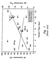
- Literature data (Table 1 and FIG. 1 ) were obtained at lower H 2 /CO ratio (2:1) and longer contact time (3 sec or longer) in a fixed bed type reactor.
- Low H 2 /CO especially 2-2.5
- long contact time low temperature
- higher pressure favor Fischer-Tropsch synthesis.
- Selectivity to CH 4 is significantly increased by increasing H 2 /CO ratio from 2 to 3.
- Increasing contact time also has a dramatic favorable effect on the catalyst performance.
- the present invention includes a catalyst structure and method of making the catalyst structure for Fischer-Tropsch synthesis that have a first porous structure with a first pore surface area and a first pore size of at least about 0.1 ⁇ m, preferably from about 10 ⁇ m to about 300 ⁇ m.
- a Fischer-Tropsch catalyst selected from the group consisting of cobalt, ruthenium, iron, nickel, rhenium, osmium and combinations thereof is placed upon the second pore surface area.
- the present invention also provides a method of making a Fischer-Tropsch catalyst having the steps of: providing a catalyst structure comprising a porous support with a first pore surface area and a first pore size of at least about 0.1 ⁇ m; optionally depositing a buffer layer on the porous support; depositing a porous interfacial layer with a second pore surface area and a second pore size less than said first pore size, upon the buffer layer (if present); and depositing a Fischer-Tropsch catalyst upon the second pore surface area.
- the present invention further includes a method of Fischer-Tropsch synthesis having the steps of:
- the present invention also includes various supported Fischer-Tropsh catalysts that are characterized by their properties.
- a catalyst is provided that, if exposed to a feed stream consisting of a 3 to 1 ratio of hydrogen gas to carbon monoxide, at 250°C and a residence time of 12.5 seconds, exhibits a selectivity to methane that is greater at 24 atmospheres (contact time of 1 second) than it is at 6 atmospheres pressure (contact time of 4 seconds), even though the conversion is higher at lower pressure.
- Catalytic activity is an intrinsic property of a catalyst.
- this property is defined by various testing conditions.
- a preferred catalyst has a Fischer-Tropsch catalytic metal supported on a porous support; where the catalyst possesses catalytic activity such that, if the catalyst is placed in a tube inside an isothermal furnace and exposed to a feed stream consisting of a 3 to 1 ratio of hydrogen gas to carbon monoxide, at 250°C, at 6 atm, at a contact time less than 5 seconds and the product stream is collected and cooled to room temperature, the selectivity to methane is less than 25%, and the carbon monoxide conversion is greater than 25%.
- a catalyst meets a claimed activity property requires only a test at the specified conditions.
- the invention also provides a method for hydrogenating carbon monoxide, in which a feed stream containing hydrogen and carbon monoxide is passed into a reaction chamber that contains a catalyst at a temperature of at least 200°C; the catalyst having a supported Fischer-Tropsch catalytic metal; and collecting a product stream.
- heat is transferred from the reaction chamber at a sufficient rate such that, under steady-state conditions, the feed stream has: a contact time of less than about 2 seconds; a production rate of at least 1 milliliter per minute of liquid product where the liquid product is measured at 20°C and 1 atm or at least 1 liter per minute of gaseous hydrocarbon product of molecules having at least 2 carbon atoms; a methane selectivity of less than 25%, and a carbon monoxide conversion greater than 25%.
- the hydrocarbons can be saturated, unsaturated or partially oxidized; and for use as fuels are preferably saturated hydrocarbons.
- the present invention further includes reactors that use any of the catalysts described herein.
- the invention also includes hydrocarbon fuels made by any of the methods described herein.
- the present invention further includes methods of hydrogenating carbon monoxide that use any of the catalysts described herein.
- Advantages that may be provided by the invention include (i) at residence/contact times shorter than the prior art, higher conversions are achieved with no increase to methane selectivity; and (ii) as residence/contact times increase, conversion increases and methane selectivity decreases.
- carbon monoxide can be hydrogenated at short contact time to produce liquid fuels at good conversion levels, low methane selectivities and good production rates.
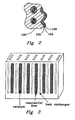
- a catalyst of the present invention is depicted in FIG. 1 having a porous support 100, a buffer layer 102. an interfacial layer 104, and, optionally, a catalyst layer 106. Any layer may be continuous or discontinuous as in the form of spots or dots, or in the form of a layer with gaps or holes.
- the porous support 100 may be a porous ceramic or a porous metal.
- Porous supports suitable for use in the present invention include carbides, nitrides, and composite materials.
- the porous support Prior to depositing the layers, the porous support preferably has a porosity of about 30% to about 99%, more preferably 60% to 98%, as measured by mercury porosimetry and an average pore size of from 1 ⁇ m to 1000um as measured by optical and scanning electron microscopy.
- Preferred forms of porous supports are foams, felts, wads and combinations thereof.
- Foam is a structure with continuous walls defining pores throughout the structure.
- Felt is a structure of fibers with interstitial spaces therebetween. Wad is a structure of tangled strands, like steel wool.
- porous supports may also include other porous media such as pellets and honeycombs, provided that they have the aforementioned porosity and pore size characteristics.
- the open cells of a metal foam preferably range from about 20 pores per inch (ppi) to about 3000 ppi and more preferably about 40 to about 600 ppi.
- PPI is defined as the largest number of pores per inch (in isotropic materials the direction of the measurement is irrelevant; however, in anisotropic materials, the measurement is done in the direction that maximizes pore number).
- ppi is measured by scanning electron microscopy. It has been discovered that a porous support provides several advantages in the present invention including low pressure drop, enhanced thermal conductivity over conventional ceramic pellet supports, and ease of loading/unloading in chemical reactors.
- the buffer layer 102 if present, has different composition and/or density than both the support and the interfacial layers, and preferably has a coefficient of thermal expansion that is intermediate to the thermal expansion coefficients of the porous support and the interfacial layer.
- the buffer layer is a metal oxide or metal carbide. Applicants discovered that vapor-deposited layers are superior because they exhibit better adhesion and resist flaking even after several thermal cycles.
- the buffer layer is Al 2 O 3 , TiO 2 , SiO 2 , and ZrO 2 or combinations thereof. More specifically, the Al 2 O 3 is ⁇ -Al 2 O 3 , ⁇ -Al 2 O 3 and combinations thereof. ⁇ -Al 2 O 3 is more preferred because of its excellent resistance to oxygen diffusion.
- the buffer layer may also be formed of two or more compositionally different sublayers.
- the porous support 100 is metal, for example a stainless steel foam
- a preferred embodiment has a buffer layer 102 formed of two compositionally different sub-layers (not shown).
- the first sublayer (in contact with the porous support 100) is preferably TiO 2 because it exhibits good adhesion to the porous metal support 100.
- the second sublayer is preferably ⁇ -Al 2 O 3 which is placed upon the TiO 2 .
- the ⁇ -Al 2 O 3 sublayer is a dense layer that provides excellent protection of the underlying metal surface. A less dense, high surface area alumina interfacial layer may then be deposited as support for a catalytically active layer.
- the porous support 100 has a thermal coefficient of expansion different from that of the interfacial layer 104. Accordingly, for high temperature catalysis (T > 150 °C) a buffer layer 102 can be used to transition between two coefficients of thermal expansion.
- the thermal expansion coefficient of the buffer layer can be tailored by controlling the composition to obtain an expansion coefficient that is compatible with the expansion coefficients of the porous support and interfacial layers.
- Another advantage of the buffer layer 102 is that it provides resistance against side reactions such as coking or cracking caused by a bare metal foam surface. For chemical reactions which do not require large surface area supports such as catalytic combustion, the buffer layer 102 stabilizes the catalyst metal due to strong metal to metal-oxide interaction.
- the buffer layer 102 provides stronger bonding to the high surface area interfacial layer 104.
- the buffer layer is free of openings and pin holes - this provides superior protection of the underlying support.
- the buffer layer is nonporous.
- the buffer layer has a thickness that is less than one half of the average pore size of the porous support.
- the buffer layer is between about 0.05 and about 10 ⁇ m thick, more preferably, less than 5 um thick: The buffer layer should exhibit thermal and chemical stability at elevated temperatures.
- adequate adhesion and chemical stability can be obtained without a buffer layer, so the buffer layer can be omitted, thus saving cost, providing extra volume and further enhancing heat transfer from the catalyst.
- the interfacial layer 104 can be comprised of nitrides, carbides, sulfides, halides, metal oxides, carbon and combinations thereof.
- the interfacial layer provides high surface area and/or provides a desirable catalyst-support interaction for supported catalysts.
- the interfacial layer can be comprised of any material that is conventionally used as a catalyst support.
- the interfacial layer is a metal oxide.
- metal oxides include, but are not limited, to ⁇ -Al 2 O 3 , SiO 2 , ZrO 2 , TiO 2 , tungsten oxide, magnesium oxide, vanadium oxide, chromium oxide, manganese oxide, iron oxide, nickel oxide, cobalt oxide, copper oxide, zinc oxide, molybdenum oxide, tin oxide, calcium oxide, aluminum oxide, lanthanum series oxide(s), zeolite(s) and combinations thereof.
- the interfacial layer 104 may serve as a catalytically active layer without any further catalytically active material deposited thereon. Usually, however, the interfacial layer 104 is used in combination with catalytically active layer 106.
- the interfacial layer may also be formed of two or more compositionally different sublayers.
- the interfacial layer has a thickness that is less than one half of the average pore size of the porous support.
- the interfacial layer thickness ranges from about 0.5 to about 100 ⁇ m, more preferably from about 1 to about 50 ⁇ m.
- the interfacial layer can be either crystalline or amorphous and preferably has a BET surface area of at least 1 m 2 /g.
- the catalytically active material 106 (when present) can be deposited on the interfacial layer 104. Alternatively, a catalytically active material can be simultaneously deposited with the interfacial layer.
- the catalytically active layer (when present) is typically intimately dispersed on the interfacial layer. That the catalytically active layer is "disposed on” or “deposited on” the interfacial layer includes the conventional understanding that microscopic catalytically active particles are dispersed: on the support layer (i.e., interfacial layer) surface, in crevices in the support layer, and in open pores in the support layer.
- the present invention employs a Fischer-Tropsch catalytic metal in the catalytically active layer.
- Catalytic metals in the present invention are preferably iron, cobalt, ruthenium, rhenium, osmium and combinations thereof.
- a promoter may be added. Promoters could include transition metals and metal oxides (except Au and Hg), lanthanide metals or metal oxides, and group IA elements (except H).
- a Fischer-Tropsch catalytic metal combined with a suitable support such as the porous support with interfacial layer described herein is termed a supported Fischer-Tropsch catalytic metal.
- the supported Fischer-Tropsch catalytic metal can be a Fischer-Tropsch catalytic metal supported on other supports such as a powder.
- the catalyst impregnation preferably forms a porous interfacial layer having a depth less than 50 ⁇ m, preferably less than 20 ⁇ m. Therefore, the diffusion path length is at least a factor of 5 shorter than for standard catalyst particles.
- the thinner impregnated catalyst structure also enhances heat transfer, due to a shorter heat transfer pathway, and leads to lower selectivity to CH 4 .
- the catalyst structure may be any geometric configuration.
- the catalyst is a porous structure such as a foam, felt, wad and combinations thereof.
- the catalyst (including the support and Fischer-Tropsch catalytic metal). preferably is sized to fit within a reaction chamber.
- the catalyst may be a single piece of porous contiguous material, or many pieces in physical contact.
- the catalyst is preferred to have contiguous material and contiguous porosity such that molecules can diffuse through the catalyst.
- the catalyst can be disposed in a reaction chamber such that gases will flow substantially through the catalyst (single or multiple pieces) rather than around it.
- the cross-sectional area of the catalyst occupies at least 80%, more preferably at least 95% of the cross-sectional area of the reaction chamber.
- the catalytically active metal is distributed on surfaces throughout catalyst such that reactants passing through the catalyst can react anywhere along the passage through the catalyst; this is a significant advantage over pellet-type catalysts that have a large volume of unused space or catalytically ineffectively used space in the pellet's interior.
- the porous catalyst is also superior over powders because packed powders may cause a severe pressure drop.
- the catalyst preferably has a surface area, as measured by BET, of greater than about 0.5 m 2 /g, more preferably greater than about 2.0 m 2 /g.
- the catalyst structure is not required to be attrition resistant as would be with the catalyst particles used in a fluidized bed reactor, greater porosity may be used, for example porosity greater than about 30%, thus, enhancing mass transfer in the catalyst structure.
- Catalysts of the present invention can also be characterized by the properties they exhibit. Factors that can be controlled to effect these properties include: selection of the porous support, buffer, interfacial, and catalytically active layers; gradation of thermal expansion coefficients, crystallinity, metal-support interactions, catalyst size, thermal conductivity of the support, porosity, thermal conductance from reaction chamber, deposition techniques and other factors as are apparent in view of the descriptions herein.
- Certain preferred embodiments of the catalysts of the present invention exhibit one or more of the following properties: adhesion - after 3 thermal cycles in air, the catalyst exhibits less than 2% (by area) of flaking as viewed by SEM (scanning electron microscope) analysis; oxidation resistance, conversion of carbon monoxide, contact times, methane selectivity, pressure drop and production rates.
- Oxidation resistance can be measured by thermal gravity analysis (TGA). After heating at 580°C in air for 2500 minutes, the catalyst increases in weight by less than 5%, more preferably less than 3%; still more preferably, after heating at 750°C in air for 1500 minutes, the catalyst increases in weight by less than 0.5%.
- TGA thermal gravity analysis
- Another aspect of the present invention is a catalyst and method utilizing the catalyst that provides lower methane selectivity at lower pressures. It was unexpectedly discovered that by using the porous catalyst structure of the present invention, reducing the pressure of the Fischer-Tropsch reaction resulted in increased yield, less selectivity toward methane. See Example 2.
- Enhanced heat transfer in the present invention enables short contact times, good conversion, and low methane selectivities.
- Various factors that can be used to enhance heat transfer include: use of a metal support, preferably a porous metal support such as a metal foam or wad, thin buffer (if present) and interfacial layers, a heat exchanger in thermal contact with the reaction chamber, microchannels in reaction chamber and/or heat exchanger, and a catalyst that has a thickness in the direction of heat transfer (e.g., the direction to the reaction chamber walls and substantially perpendicular to the direction of flow) of about 1.5 cm or less, more preferably about 1 to 10 mm, and still more preferably about 1 to 3 mm.
- the invention further provides apparatusses (i.e., reactors) and methods for hydrogenating carbon monoxide.
- the catalytic process is conducted in apparatus having microchannels.
- a microchannel has a characteristic dimension less than about 1 mm.
- the reaction chamber has walls defining at least one microchannel through which pass reactants into the reaction chamber.
- the reaction chamber walls separate the reaction chamber from at least one cooling chamber. Examples of suitable microchannel apparatus and various process related factors are described in U.S. Patents Nos. 5,611,214 , 5,811,062 , 5,534,328 , and U.S. Patent Applications Ser. Nos.
- the catalyst is a monolith - a single contiguous, yet porous, piece of catalyst or several contiguous pieces that are stacked together (not a bed of packed powder or pellets or a coating on the wall of a microchannel) that can easily be inserted and extracted from a reaction chamber.
- the piece or stack of catalyst pieces preferably have a width of 0.1 mm to about 2 cm, with a preferred thickness of less than about 1.5 cm, more preferably less than about 1.0 cm, and still more preferably, about 1 to about 3 mm.
- the inventive catalyst may provide numerous advantages to catalytic processes such as: chemical stability, stability to repeated thermal cycling, thermal stability, efficient loading and unloading of catalysts, high rates of heat transfer and mass transfer, and maintenance of desired catalytic activity.
- the metal surfaces within microchannel apparatus can be coated with either or both the buffer and the interfacial layers. This can be done using any of the processes described herein, preferably by vapor deposition. Preferred coating materials include titania and and 5-10% SiO 2 /Al 2 O 3 .
- the interior surfaces of the reaction chamber, heat exchanger and other surfaces of microchannel apparatus may be coated.
- the walls of a reaction chamber can be coated with an optional buffer layer, an interfacial layer, and a catalytically active material - typically the catalytically active material and the interfacial layer combine to form a supported catalyst. Coatings can also be applied to metal walls in tubes and pipes that form connections to or within microchannel apparatus.
- residence time less than 5 seconds can be achieved by: (a) providing a catalyst structure of a metal foam having a catalyst thereon; and (b) passing a feed stream having a mixture of hydrogen gas with carbon monoxide gas through the catalyst structure and heating the catalyst structure to at least 200 °C, thereby obtaining a product stream of at least 25% conversion of carbon monoxide, and at most 25% selectivity toward methane.
- the catalyst structure includes a buffer layer and an interfacial layer with a catalytically active metal disposed on the interfacial layer.
- the present invention provides processes for hydrogenating carbon monoxide.
- the ratio of hydrogen to carbon monoxide ranges from about 1:1 to about 6:1, preferably from about 2:1 to about 3.5:1.
- Hydrogenation is preferably conducted at temperatures above about 200°C, more preferably between about 200°C and about 300°C. and still more preferably between about 200°C and about 270°C.
- Certain embodiments of the present invention can be characterized in terms of residence or contact time. These terms have well-defined meanings in the art.
- Contact time is the total volume of the catalyst chambers divided by the total flowrate of inlet reactants assuming they are an ideal gas corrected to standard conditions (i.e., the volume of the catalyst chamber / F-total at STP where STP is 273K and 1 atm).
- the volume of the catalyst chambers includes the volume in immediate proximity and surrounding the catalyst zone. As an example, if one were to pack one quarter of the channels with powders, then the volume of the catalyst chamber would only include that region where gas can flow and where it can contact the catalyst, i.e. only one quarter of the total channel volume would be included in this calculation.
- Average residence time is the total volume of the catalyst chambers divided by the total flowrate of inlet reactants, corrected to the actual temperature and pressure of the reactants in the reactor (i.e., the volume of the catalyst chamber / F-total corrected to actual conditions).
- F-total at STP is the total volumetric flowrate of reactants (includes all reactants, and diluents if present).
- Inlet gases are typically metered with mass flow controllers set to standard conditions, i.e. the user presets the desired STP flowrate.
- F-total corrected to actual conditions F-total-STP x (Temperature in K)1273 x 1 atm/(P actual in atm): this value is used to calculate the residence time or the 'true time' within a reactor. Most practitioners prefer to use contact time, because it is a convenient method to keep the time variable fixed while stepping through 10 degree C increments in reaction temperature etc.
- the inventive method is preferably carried out in a reaction chamber in which the catalyst has a thickness of about 1.5 cm or less and is touching or in close proximity (within about 1 mm) of a reaction chamber wall, where the reaction chamber wall is in thermal contact with a heat exchanger. Heat transfer from the reaction chamber is preferably enhanced by addition of microchannels on at least one reaction chamber wall on the side of the reaction chamber wall opposite the catalyst structure.
- the catalyst preferably has contiguous and relatively large pores, such as in a foam, to avoid large pressure drops.
- the pore size of the large pores in the catalyst is between about 10 ⁇ m and about 300 ⁇ m.
- carbon monoxide hydrogenation is conducted at a contact time of less than 5 seconds, more preferably, less than about 2 seconds and still more preferably between about 0.1 and about 1 seconds. At these contact times, good CO conversion and low methane selectivity can be obtained.
- CO conversion is at least 25%, more preferably, at least 50%, and still more preferably, greater than about 80%.
- Methane selectivity is preferably less than 25%, more preferably less than about 20%, and still more preferably, between about 15% and 5%.
- these properties can be achieved with low pressure drops across the reaction chamber.
- the pressure drop through the reaction chamber is preferably less than about 15 psig, more preferably less than 10 psig, still more preferably less than about 5 psig, and yet more preferably less than about 1 psig.
- a method of making the inventive catalyst has the steps of selecting a porous support 100, optionally depositing a buffer layer 102 on the porous support 100 and depositing an interfacial layer 104 thereover.
- a catalyst layer 106 may be deposited onto the interfacial layer 104. or both the interfacial layer and the catalyst layer may be simultaneously deposited on the buffer layer 102.
- metal foam is etched prior to vapor depositing the buffer layer 102. Etching is preferably with an acid, for example HCl.
- Deposition of the buffer layer 102 is preferably by vapor deposition including but not limited to chemical vapor deposition, physical vapor deposition or combinations thereof. Surprisingly, it has been found that vapor deposition, which is typically conducted at high temperatures, results in polycrystalline or amorphous phases that provide good adhesion of the buffer layer to the surface of the porous support. The method is particularly advantageous for adhering a metal oxide buffer layer to a metal porous support.
- the buffer layer 102 may be obtained by solution coating.
- the solution coating has the steps of metal surface functionalization via exposing the metal surface to water vapor to form suface hydroxyls, followed by surface reaction and hydrolysis of alkoxides to obtain a coating of metal oxide. This solution coating may be preferred as a lower cost method of depositing the buffer layer 102.
- the interfacial layer 104 is preferably formed by vapor or solution deposition using precursors as are known for these techniques. Suitable precursors include organometallic compounds, halides, carbonyls, acetonates, acetates, metals, colloidal dispersions of metal oxides, nitrates, slurries, etc.
- a porous alumina interfacial layer can be wash-coated with PQ alumina (Nyacol Products, Ashland, MA) colloidal dispersion followed by drying in a vacuum oven overnight and calcining at 500°C for 2 hours.
- the catalytically active material can be deposited by any suitable method.
- catalytic metal precursors can be deposited on colloidal metal oxide particles and slurry coated on a porous support, then dried and reduced.
- the effect of residence time and reaction temperature on the catalytic conversion of CO with H 2 was examined in a constant flow reactor.
- This reactant feed was fed into a reaction chamber, which was maintained at a constant temperature inside an isothermal furnace.
- the interior of the catalyst chamber measures 35.6-mm (1.4-in) in length, 1.5-mm (0.060-in) in thickness and 8-mm (0.315-in) in width.
- the reaction products then exited the reaction chamber and were collected and analyzed for composition.
- the catalyst for this experiment was prepared as follows. First, acidic gamma-alumina support powder (Strem) was ground and sieved to between 70-and 100-mesh (150 to 220-micron), and calcined (stabilized) at 500°C for several hours. This powder was then impregnated with a solution containing cobalt nitrate hexahydrate and ruthenium trichloride hydrate (or ruthenium nitrosyl nitrate) precursors, present in desired concentrations as to produce a 15-wt% cobalt, 1-wt% ruthenium on alumina catalyst.
- the precursor solution was prepared in such a manner as to saturate the pore volume of the alumina support without over saturation of the alumina support.
- This powder was then dried in a vacuum oven at 100°C for at least 4-hours, followed by drying at 100°C for at least 12-hours.
- the powder was then calcined by heating at 350°C for at least 3-hours.
- a portion of the powder was then combined with distilled water in a water-to-catalyst weight ratio of at least 2.5 to produce a catalyst slurry.
- This catalyst slurry is then placed in a container with inert grinding media balls and placed on a rotating device for at least 24-hours. This slurry was then ready to coat a pre-treated metal foam monolith type support.
- the metal foam support monolith is typically 80-ppi (pores per inch) stainless steel (supplied by AstroMet, Cincinnati, Ohio), with characteristic macropores on the order of about 200- to 250- ⁇ m, and with a porosity of about 90% (by volume).
- the monolith pretreatment consists of cleaning successively in dichloromethane and acetone solvents in a water bath submersed in a sonication device to agitate the solvent within the monolith.
- the metal surface of the monolith may then be roughened by etching with acid. If this is desired, the monolith is submerged in 0.1-molar nitric acid, and placed in a sonication device. The monolith was then rinsed in distilled water and dried at about 100°C.
- the monolith was then coated with a layer of alumina using a chemical vapor deposition (CVD) technique.
- the CVD system has a horizontal, hot-wall reactor with three precursor sources. The CVD coatings are performed at a deposition temperature of 600°C and reactor pressure of 5-torr.
- Aluminum iso-propoxide was used as the aluminum precursor. This precursor is stored in a quartz container maintained at 100°C during deposition, which produces a vapor that is carried into the CVD reactor by a flow of nitrogen carrier gas for about 20-minutes. Air was then used to oxidize the aluminum precursor to alumina. Typical thickness of the alumina coatings is about 0.5- ⁇ m.
- This pretreated metal support foam monolith was then coated with the catalyst slurry by dip coating.
- the monolith was then dried in flowing air or nitrogen at room temperature white continuously rotating the monolith in such a way as to create a uniform coverage of the dried catalyst slurry layer.
- the monolith was then dried at 90°C for at least 1-hour, heated slowly to 120°C over the course of at least-hour, dried further at 120°C for at least 2-hours, and then heated to 350°C and calcined for at least 3-hours.
- 0.1-0.25 g of alumina supported Co-Ru powder catalyst was coated on the metal foam monolith with dimensions and characteristics aforementioned.
- the catalyst monolith or powder weighing approximately 0.5 grams was then placed inside the reaction chamber and activated (or reduced) prior to reaction by heating to about 350°C to 400°C and under flow of a hydrogencontaining stream of about 10- to 20-% (by mole or volume) hydrogen in an inert carrier gas (such as nitrogen or helium) at a flow rate of at least 20 cc/min (measured at 273K and 1-atm) for at least 2-hours.
- the catalyst was then allowed to cool to reaction temperatures, at least 200°C.
- the catalyst was then exposed to a feed gas comprised of H 2 and CO in a desired ratio of moles of H 2 per mole of CO.
- the feed gas flow rate is controllable to allow for precise generation of a desired contact time, usually about 1-second.
- the reaction products were then analyzed to evaluate the conversion of CO and the selectivity towards certain products, such as methane.
- the reaction was conducted at pressures up to 24-atmospheres (about 353-psia).
- Table E1-1 shows the results of these experiments.
- the powder form of the catalyst produced greater conversions at a given temperature than the monolithic form.
- the monolith catalyst produced less methane.
- methane formation is predominately affected by reactor temperature and feed composition, although it is also affected to a lesser extent by other parameters, such as contact time.
- the fact that the monolithic catalyst yields lower methane selectivity at a given temperature suggests that the monolith is better able to conduct heat away from the inner part of the reactor, and thus avoid higher local temperatures, which are often present in the inner sections of packed or powder beds.
- conversion is a strong function of both temperature and contact time, and conversion will increase with increasing temperature and/or time. Decreasing the contact time from 2-seconds to 1-sec at 275°C for the monolithic catalysts resulted in lower conversion and higher methane selectivity.
- the thickness of the catalyst layer in the monolith is much less than finest particle size used either in fixed bed reactors (>100 ⁇ m), or slurry type or fluidized type reactors (>50- ⁇ m). Therefore, the internal mass transfer diffusion pathway is shorter in the monolith catalyst.
- internal pores within the catalyst are normally filled with hydrocarbon products, and hydrogen has much higher diffusivities than that of CO. This could result in much higher H 2 /CO ratio inside a pellet or powder catalyst than that in the bulk feed, which favors methanation. Therefore, the thinner catalyst layer with the monolith catalyst will result in a relatively lower local H 2 concentration within the catalyst to minimize the selectivity to methane.
- Titanium isopropxide (Strem Chemical, Newburyport, MA) was vapor deposited at a temperature ranging from 250 to 800°C at a pressure of 0.1 to 100 torr. Titania coatings with excellent adhesion to the foam were obtained at a deposition temperature of 600°C and a reactor pressure of 3 torr.
Abstract
Description
- The present invention is a catalyst structure and method of making, and a method of Fischer-Tropsch synthesis.
- Fischer-Tropsch synthesis is carbon monoxide hydrogenation that is usually performed on a product stream from another reaction including but not limited to steam reforming (product stream H2/CO -3), partial oxidation (product stream H2/CO -2), autothermal reforming (product stream H2/CO -2.5), CO2 reforming (H2/CO -1) coal gassification (product stream H2/CO -1) and combinations thereof.
- Fundamentally, Fischer-Tropsch synthesis has fast surface reaction kinetics. However, the overall reaction rate is severely limited by heat and mass transfer with conventional catalysts or catalyst structures. The limited heat transfer together with the fast surface reaction kinetics may result in hot spots in a catalyst bed. Hot spots favor methanation. In commercial processes, fixed bed reactors with small internal diameters or slurry type and fluidized type reactors with small catalyst particles (>50 microns, µm) are used to mitigate the heat and mass transfer limitations. In addition, one of the important reasons that Fischer-Tropsch reactors are operated at lower conversions per pass is to minimize temperature excursion in the catalyst bed. Because of the necessary operational parameters to avoid methanation, conventional reactors are not improved even with more active Fischer-Tropsch synthesis catalysts. Detailed operation is summarized in Table 1 and
FIG. 1 .Table 1 - Comparison of Contact Times Effects in Fischer-Tropsch Experimentation Rev(A) Catalyst Conditions Contact time Conversion CH4 selectivity 1 Co/ZSM-5 240°C. 20-atm, H2/CO=2 3.6-sec 60 % 21 % 2 Co/MnO 220°C, 21-atm, H2/CO=2 0.72-sec 13 % 15 % 3 Co-Ru/TiO2 200°C, 20-atm, H2/CO=2 3-sec 61 % 5 % Co/TiO2 " 8-sec 49 % 7 % 4 Co/TiO2 200°C, 20-atm, H2/CO=2.1 2-sec 9.5 % ∼9 % " 12-sec 72 % ∼6 % 5 Ru/Al2O3 222°C. 21-atm, H2/CO=3 4.5-sec 20 % ? " 7.2-sec 36 % " 8.4-sec 45 % " 9.6-sec 51 % " 12-sec 68 % " 14-sec 84 % 6 Ru/Al2O3 250°C. 22-atm. H2/CO=2 7.2-sec 38 % 5 % 7 Ru/ Al2O3 225°C. 21-atm. H2/CO=2 12-sec 66 % 13 % 222°C. 21-atm. H2/CO=3 12-sec 77 % 34 % For references that contained results for multiple experimental conditions. the run which best matched our conversion. selectivity and/or conditions was chosen for comparison of contact time.
(A) References
1. Bessell, S., Appl. Catal. A: Gen. 96. 253 (1993).
2. Hutchings, G.J., Topics Catal. 2. 163 (1995).
3. Iglesia. E., S.L. Soled and R.A. Fiato (Exxon Res. and Eng. Co.).U.S. patent 4,738.948, Apr. 19, 1988 .
4. Iglesia. E., S.C. Reyes, R.J. Madon and S.L. Soled. Adv. Catal. 39. 321 (1993).
5. Karn, F.S., J.F. Shultz and R.B. Anderson, Ind. Eng. Chem. Prod Res. Dev. 4(4), 265 (1965).
6. King, F.. E. Shutt and A.I. Thomson. Platinum Metals Rev. 29(44). 146 (1985).
7. Shultz. J.F., F.S. Karn and R.B. Anderson. Rep. Invest. - U.S. Bur. Mines 6974. 20 (1967). - Literature data (Table 1 and
FIG. 1 ) were obtained at lower H2/CO ratio (2:1) and longer contact time (3 sec or longer) in a fixed bed type reactor. Low H2/CO (especially 2-2.5), long contact time, low temperature, and higher pressure favor Fischer-Tropsch synthesis. Selectivity to CH4 is significantly increased by increasing H2/CO ratio from 2 to 3. Increasing contact time also has a dramatic favorable effect on the catalyst performance. Although reference 3 in Table 1 shows satisfactory results, the experiment was conducted under the conditions where Fischer-Tropsch synthesis is favored (at least 3 sec residence time, and H2/CO=2). In addition, the experiment of reference 3 was done using a powdered catalyst on an experimental scale that would be impractical commercially because of the pressure drop penalty imposed by powdered catalyst. Operating at higher temperature will enhance the conversion, however at the much higher expense of selectivity to CH4. It is also noteworthy that contact time in commercial Fischer-Tropsch units is at least 10 sec. - Hence, there is a need for a catalyst structure and method of Fischer-Tropsch synthesis that can achieve the same or higher conversion at shorter contact time. and/or at higher H2/CO.
- The present invention includes a catalyst structure and method of making the catalyst structure for Fischer-Tropsch synthesis that have a first porous structure with a first pore surface area and a first pore size of at least about 0.1 µm, preferably from about 10 µm to about 300 µm. A porous interfacial layer with a second pore surface area and a second pore size less than the first pore size disposed on the first pore surface area. A Fischer-Tropsch catalyst selected from the group consisting of cobalt, ruthenium, iron, nickel, rhenium, osmium and combinations thereof is placed upon the second pore surface area.
- The present invention also provides a method of making a Fischer-Tropsch catalyst having the steps of: providing a catalyst structure comprising a porous support with a first pore surface area and a first pore size of at least about 0.1 µm; optionally depositing a buffer layer on the porous support; depositing a porous interfacial layer with a second pore surface area and a second pore size less than said first pore size, upon the buffer layer (if present); and depositing a Fischer-Tropsch catalyst upon the second pore surface area.
- The present invention further includes a method of Fischer-Tropsch synthesis having the steps of:
- providing a catalyst structure having a first porous support with a first pore surface area and a first pore size of at least about 0.1 µm;
- optionally, a buffer layer disposed on the porous support:
- a porous interfacial layer with a second pore surface area and a second pore size less than the first pore size, the porous interfacial layer disposed on the buffer layer (if present) or on the first pore surface area; and
- a Fischer-Tropsch catalyst disposed on the second pore surface area; and
- passing a feed stream having a mixture of hydrogen gas and carbon monoxide gas through the catalyst structure and heating the catalyst structure to at least 200°C at an operating pressure, the feed stream having a residence time within the catalyst structure less than 5 seconds, thereby obtaining a product stream of at least 25% conversion of carbon monoxide, and at most 25% selectivity toward methane.
- The present invention also includes various supported Fischer-Tropsh catalysts that are characterized by their properties. For example, a catalyst is provided that, if exposed to a feed stream consisting of a 3 to 1 ratio of hydrogen gas to carbon monoxide, at 250°C and a residence time of 12.5 seconds, exhibits a selectivity to methane that is greater at 24 atmospheres (contact time of 1 second) than it is at 6 atmospheres pressure (contact time of 4 seconds), even though the conversion is higher at lower pressure.
- Catalytic activity is an intrinsic property of a catalyst. In the present invention, this property is defined by various testing conditions. For example, a preferred catalyst has a Fischer-Tropsch catalytic metal supported on a porous support; where the catalyst possesses catalytic activity such that, if the catalyst is placed in a tube inside an isothermal furnace and exposed to a feed stream consisting of a 3 to 1 ratio of hydrogen gas to carbon monoxide, at 250°C, at 6 atm, at a contact time less than 5 seconds and the product stream is collected and cooled to room temperature, the selectivity to methane is less than 25%, and the carbon monoxide conversion is greater than 25%. To check whether a catalyst meets a claimed activity property requires only a test at the specified conditions.
- The invention also provides a method for hydrogenating carbon monoxide, in which a feed stream containing hydrogen and carbon monoxide is passed into a reaction chamber that contains a catalyst at a temperature of at least 200°C; the catalyst having a supported Fischer-Tropsch catalytic metal; and collecting a product stream. In this process, heat is transferred from the reaction chamber at a sufficient rate such that, under steady-state conditions, the feed stream has: a contact time of less than about 2 seconds; a production rate of at least 1 milliliter per minute of liquid product where the liquid product is measured at 20°C and 1 atm or at least 1 liter per minute of gaseous hydrocarbon product of molecules having at least 2 carbon atoms; a methane selectivity of less than 25%, and a carbon monoxide conversion greater than 25%. The hydrocarbons can be saturated, unsaturated or partially oxidized; and for use as fuels are preferably saturated hydrocarbons.
- The present invention further includes reactors that use any of the catalysts described herein. The invention also includes hydrocarbon fuels made by any of the methods described herein. The present invention further includes methods of hydrogenating carbon monoxide that use any of the catalysts described herein.
- Advantages that may be provided by the invention include (i) at residence/contact times shorter than the prior art, higher conversions are achieved with no increase to methane selectivity; and (ii) as residence/contact times increase, conversion increases and methane selectivity decreases. Surprisingly, it has been found that carbon monoxide can be hydrogenated at short contact time to produce liquid fuels at good conversion levels, low methane selectivities and good production rates.
- The subject matter of the present invention is particularly pointed out and distinctly claimed in the concluding portion of this specification. However, both the organization and method of operation, together with further advantages and objects thereof, may best be understood by reference to the following description taken in connection with accompanying drawings wherein like reference characters refer to like elements.
-
-
FIG. 1 is a graph of CO conversion versus contact time for prior art Fischer-Tropsch processes. -
FIG. 2 is a cross section of a catalyst structure according to the present invention. -
FIG. 3 illustrates a reactor design having multiple reaction chambers, each containing a catalyst, and multiple heat exchangers. - A catalyst of the present invention is depicted in
FIG. 1 having a porous support 100, a buffer layer 102. an interfacial layer 104, and, optionally, a catalyst layer 106. Any layer may be continuous or discontinuous as in the form of spots or dots, or in the form of a layer with gaps or holes. - The porous support 100 may be a porous ceramic or a porous metal. Porous supports suitable for use in the present invention include carbides, nitrides, and composite materials. Prior to depositing the layers, the porous support preferably has a porosity of about 30% to about 99%, more preferably 60% to 98%, as measured by mercury porosimetry and an average pore size of from 1µm to 1000um as measured by optical and scanning electron microscopy. Preferred forms of porous supports are foams, felts, wads and combinations thereof. Foam is a structure with continuous walls defining pores throughout the structure. Felt is a structure of fibers with interstitial spaces therebetween. Wad is a structure of tangled strands, like steel wool. Less preferably, porous supports may also include other porous media such as pellets and honeycombs, provided that they have the aforementioned porosity and pore size characteristics. The open cells of a metal foam preferably range from about 20 pores per inch (ppi) to about 3000 ppi and more preferably about 40 to about 600 ppi. PPI is defined as the largest number of pores per inch (in isotropic materials the direction of the measurement is irrelevant; however, in anisotropic materials, the measurement is done in the direction that maximizes pore number). In the present invention, ppi is measured by scanning electron microscopy. It has been discovered that a porous support provides several advantages in the present invention including low pressure drop, enhanced thermal conductivity over conventional ceramic pellet supports, and ease of loading/unloading in chemical reactors.
- The buffer layer 102, if present, has different composition and/or density than both the support and the interfacial layers, and preferably has a coefficient of thermal expansion that is intermediate to the thermal expansion coefficients of the porous support and the interfacial layer. Preferably, the buffer layer is a metal oxide or metal carbide. Applicants discovered that vapor-deposited layers are superior because they exhibit better adhesion and resist flaking even after several thermal cycles. More preferably, the buffer layer is Al2O3, TiO2, SiO2, and ZrO2 or combinations thereof. More specifically, the Al2O3 is α-Al2O3, γ-Al2O3 and combinations thereof. α-Al2O3 is more preferred because of its excellent resistance to oxygen diffusion. Therefore, it is expected that resistance against high temperature oxidation can be improved with alumina coated on the porous support 100. The buffer layer may also be formed of two or more compositionally different sublayers. When the porous support 100 is metal, for example a stainless steel foam, a preferred embodiment has a buffer layer 102 formed of two compositionally different sub-layers (not shown). The first sublayer (in contact with the porous support 100) is preferably TiO2 because it exhibits good adhesion to the porous metal support 100. The second sublayer is preferably α-Al2O3 which is placed upon the TiO2. In a preferred embodiment, the α-Al2O3 sublayer is a dense layer that provides excellent protection of the underlying metal surface. A less dense, high surface area alumina interfacial layer may then be deposited as support for a catalytically active layer.
- Typically the porous support 100 has a thermal coefficient of expansion different from that of the interfacial layer 104. Accordingly, for high temperature catalysis (T > 150 °C) a buffer layer 102 can be used to transition between two coefficients of thermal expansion. The thermal expansion coefficient of the buffer layer can be tailored by controlling the composition to obtain an expansion coefficient that is compatible with the expansion coefficients of the porous support and interfacial layers. Another advantage of the buffer layer 102 is that it provides resistance against side reactions such as coking or cracking caused by a bare metal foam surface. For chemical reactions which do not require large surface area supports such as catalytic combustion, the buffer layer 102 stabilizes the catalyst metal due to strong metal to metal-oxide interaction. In chemical reactions which require large surface area supports, the buffer layer 102 provides stronger bonding to the high surface area interfacial layer 104. Preferably, the buffer layer is free of openings and pin holes - this provides superior protection of the underlying support. More preferably, the buffer layer is nonporous. The buffer layer has a thickness that is less than one half of the average pore size of the porous support. Preferably, the buffer layer is between about 0.05 and about 10 µm thick, more preferably, less than 5 um thick: The buffer layer should exhibit thermal and chemical stability at elevated temperatures.
- In some embodiments of the present invention, adequate adhesion and chemical stability can be obtained without a buffer layer, so the buffer layer can be omitted, thus saving cost, providing extra volume and further enhancing heat transfer from the catalyst.
- The interfacial layer 104 can be comprised of nitrides, carbides, sulfides, halides, metal oxides, carbon and combinations thereof. The interfacial layer provides high surface area and/or provides a desirable catalyst-support interaction for supported catalysts. The interfacial layer can be comprised of any material that is conventionally used as a catalyst support. Preferably, the interfacial layer is a metal oxide. Examples of metal oxides include, but are not limited, to γ-Al2O3, SiO2, ZrO2, TiO2, tungsten oxide, magnesium oxide, vanadium oxide, chromium oxide, manganese oxide, iron oxide, nickel oxide, cobalt oxide, copper oxide, zinc oxide, molybdenum oxide, tin oxide, calcium oxide, aluminum oxide, lanthanum series oxide(s), zeolite(s) and combinations thereof. The interfacial layer 104 may serve as a catalytically active layer without any further catalytically active material deposited thereon. Usually, however, the interfacial layer 104 is used in combination with catalytically active layer 106. The interfacial layer may also be formed of two or more compositionally different sublayers. The interfacial layer has a thickness that is less than one half of the average pore size of the porous support. Preferably, the interfacial layer thickness ranges from about 0.5 to about 100 µm, more preferably from about 1 to about 50 µm. The interfacial layer can be either crystalline or amorphous and preferably has a BET surface area of at least 1 m2/g.
- The catalytically active material 106 (when present) can be deposited on the interfacial layer 104. Alternatively, a catalytically active material can be simultaneously deposited with the interfacial layer. The catalytically active layer (when present) is typically intimately dispersed on the interfacial layer. That the catalytically active layer is "disposed on" or "deposited on" the interfacial layer includes the conventional understanding that microscopic catalytically active particles are dispersed: on the support layer (i.e., interfacial layer) surface, in crevices in the support layer, and in open pores in the support layer. The present invention employs a Fischer-Tropsch catalytic metal in the catalytically active layer. Conventional Fischer-Tropsch catalsyts are based on iron (Fe), cobalt (Co), nickel (Ni), ruthenium (Ru), rhenium (Re), osmium (Os) and combinations thereof. Catalytic metals in the present invention are preferably iron, cobalt, ruthenium, rhenium, osmium and combinations thereof. In addition to these catalyst metals, a promoter may be added. Promoters could include transition metals and metal oxides (except Au and Hg), lanthanide metals or metal oxides, and group IA elements (except H). A Fischer-Tropsch catalytic metal combined with a suitable support such as the porous support with interfacial layer described herein is termed a supported Fischer-Tropsch catalytic metal. In less preferred embodiments, the supported Fischer-Tropsch catalytic metal can be a Fischer-Tropsch catalytic metal supported on other supports such as a powder.
- In order to mitigate the mass transfer limitation of the catalyst structure, the catalyst impregnation preferably forms a porous interfacial layer having a depth less than 50 µm, preferably less than 20 µm. Therefore, the diffusion path length is at least a factor of 5 shorter than for standard catalyst particles. The thinner impregnated catalyst structure also enhances heat transfer, due to a shorter heat transfer pathway, and leads to lower selectivity to CH4.
- The catalyst structure may be any geometric configuration. Preferably, the catalyst is a porous structure such as a foam, felt, wad and combinations thereof. The catalyst (including the support and Fischer-Tropsch catalytic metal). preferably is sized to fit within a reaction chamber. The catalyst may be a single piece of porous contiguous material, or many pieces in physical contact. The catalyst is preferred to have contiguous material and contiguous porosity such that molecules can diffuse through the catalyst. In this preferred embodiment, the catalyst can be disposed in a reaction chamber such that gases will flow substantially through the catalyst (single or multiple pieces) rather than around it. In a preferred embodiment, the cross-sectional area of the catalyst occupies at least 80%, more preferably at least 95% of the cross-sectional area of the reaction chamber. In preferred embodiments, the catalytically active metal is distributed on surfaces throughout catalyst such that reactants passing through the catalyst can react anywhere along the passage through the catalyst; this is a significant advantage over pellet-type catalysts that have a large volume of unused space or catalytically ineffectively used space in the pellet's interior. The porous catalyst is also superior over powders because packed powders may cause a severe pressure drop. The catalyst preferably has a surface area, as measured by BET, of greater than about 0.5 m2/g, more preferably greater than about 2.0 m2/g.
- In addition, because the catalyst structure is not required to be attrition resistant as would be with the catalyst particles used in a fluidized bed reactor, greater porosity may be used, for example porosity greater than about 30%, thus, enhancing mass transfer in the catalyst structure.
- Catalysts of the present invention can also be characterized by the properties they exhibit. Factors that can be controlled to effect these properties include: selection of the porous support, buffer, interfacial, and catalytically active layers; gradation of thermal expansion coefficients, crystallinity, metal-support interactions, catalyst size, thermal conductivity of the support, porosity, thermal conductance from reaction chamber, deposition techniques and other factors as are apparent in view of the descriptions herein. Certain preferred embodiments of the catalysts of the present invention exhibit one or more of the following properties: adhesion - after 3 thermal cycles in air, the catalyst exhibits less than 2% (by area) of flaking as viewed by SEM (scanning electron microscope) analysis; oxidation resistance, conversion of carbon monoxide, contact times, methane selectivity, pressure drop and production rates.
- Oxidation resistance can be measured by thermal gravity analysis (TGA). After heating at 580°C in air for 2500 minutes, the catalyst increases in weight by less than 5%, more preferably less than 3%; still more preferably, after heating at 750°C in air for 1500 minutes, the catalyst increases in weight by less than 0.5%. Each thermal cycle consists of heating from room temperature to 600°C in air at a heating rate of 10°C/min, maintaining the temperature at 600°C for 3000 minutes, and cooling at a rate of 10°C/min.
- Another aspect of the present invention is a catalyst and method utilizing the catalyst that provides lower methane selectivity at lower pressures. It was unexpectedly discovered that by using the porous catalyst structure of the present invention, reducing the pressure of the Fischer-Tropsch reaction resulted in increased yield, less selectivity toward methane. See Example 2.
- Enhanced heat transfer in the present invention enables short contact times, good conversion, and low methane selectivities. Various factors that can be used to enhance heat transfer include: use of a metal support, preferably a porous metal support such as a metal foam or wad, thin buffer (if present) and interfacial layers, a heat exchanger in thermal contact with the reaction chamber, microchannels in reaction chamber and/or heat exchanger, and a catalyst that has a thickness in the direction of heat transfer (e.g., the direction to the reaction chamber walls and substantially perpendicular to the direction of flow) of about 1.5 cm or less, more preferably about 1 to 10 mm, and still more preferably about 1 to 3 mm.
- The invention further provides apparatusses (i.e., reactors) and methods for hydrogenating carbon monoxide. In a preferred embodiment, the catalytic process is conducted in apparatus having microchannels. A microchannel has a characteristic dimension less than about 1 mm. In one embodiment, the reaction chamber has walls defining at least one microchannel through which pass reactants into the reaction chamber. In a preferred embodiment, the reaction chamber walls separate the reaction chamber from at least one cooling chamber. Examples of suitable microchannel apparatus and various process related factors are described in
U.S. Patents Nos. 5,611,214 ,5,811,062 ,5,534,328 , andU.S. Patent Applications Ser. Nos. 08/883,643 ,08/938,228 ,09/123,779 09/375,614 (filed Aug. 17, 1999 09/265,227 (filed Mar. 8, 1999 - The metal surfaces within microchannel apparatus can be coated with either or both the buffer and the interfacial layers. This can be done using any of the processes described herein, preferably by vapor deposition. Preferred coating materials include titania and and 5-10% SiO2/Al2O3. The interior surfaces of the reaction chamber, heat exchanger and other surfaces of microchannel apparatus may be coated. In some embodiments, the walls of a reaction chamber can be coated with an optional buffer layer, an interfacial layer, and a catalytically active material - typically the catalytically active material and the interfacial layer combine to form a supported catalyst. Coatings can also be applied to metal walls in tubes and pipes that form connections to or within microchannel apparatus.
- According a preferred method of the present invention, residence time less than 5 seconds can be achieved by: (a) providing a catalyst structure of a metal foam having a catalyst thereon; and (b) passing a feed stream having a mixture of hydrogen gas with carbon monoxide gas through the catalyst structure and heating the catalyst structure to at least 200 °C, thereby obtaining a product stream of at least 25% conversion of carbon monoxide, and at most 25% selectivity toward methane. In another preferred method, the catalyst structure includes a buffer layer and an interfacial layer with a catalytically active metal disposed on the interfacial layer.
- The present invention provides processes for hydrogenating carbon monoxide. In preferred processes, the ratio of hydrogen to carbon monoxide ranges from about 1:1 to about 6:1, preferably from about 2:1 to about 3.5:1. Hydrogenation is preferably conducted at temperatures above about 200°C, more preferably between about 200°C and about 300°C. and still more preferably between about 200°C and about 270°C.
- Certain embodiments of the present invention can be characterized in terms of residence or contact time. These terms have well-defined meanings in the art. Contact time is the total volume of the catalyst chambers divided by the total flowrate of inlet reactants assuming they are an ideal gas corrected to standard conditions (i.e., the volume of the catalyst chamber / F-total at STP where STP is 273K and 1 atm). The volume of the catalyst chambers includes the volume in immediate proximity and surrounding the catalyst zone. As an example, if one were to pack one quarter of the channels with powders, then the volume of the catalyst chamber would only include that region where gas can flow and where it can contact the catalyst, i.e. only one quarter of the total channel volume would be included in this calculation. The volume of dead space, i.e., headers, footers, etc. is ignored in this calculation. Average residence time (also referred to as residence time) is the total volume of the catalyst chambers divided by the total flowrate of inlet reactants, corrected to the actual temperature and pressure of the reactants in the reactor (i.e., the volume of the catalyst chamber / F-total corrected to actual conditions). F-total at STP is the total volumetric flowrate of reactants (includes all reactants, and diluents if present). Inlet gases are typically metered with mass flow controllers set to standard conditions, i.e. the user presets the desired STP flowrate. F-total corrected to actual conditions = F-total-STP x (Temperature in K)1273 x 1 atm/(P actual in atm): this value is used to calculate the residence time or the 'true time' within a reactor. Most practitioners prefer to use contact time, because it is a convenient method to keep the time variable fixed while stepping through 10 degree C increments in reaction temperature etc.
- Contact times less than 5 seconds may be accomplished with standard equipment but at the expense of significant energy to raise the space velocity of the reactants to overcome the pressure drop and poorer heat transfer leading to higher methane formation. Thus, the inventive method is preferably carried out in a reaction chamber in which the catalyst has a thickness of about 1.5 cm or less and is touching or in close proximity (within about 1 mm) of a reaction chamber wall, where the reaction chamber wall is in thermal contact with a heat exchanger. Heat transfer from the reaction chamber is preferably enhanced by addition of microchannels on at least one reaction chamber wall on the side of the reaction chamber wall opposite the catalyst structure. The catalyst preferably has contiguous and relatively large pores, such as in a foam, to avoid large pressure drops. Preferably the pore size of the large pores in the catalyst is between about 10 µm and about 300 µm.
- In preferred embodiments of the present invention, carbon monoxide hydrogenation is conducted at a contact time of less than 5 seconds, more preferably, less than about 2 seconds and still more preferably between about 0.1 and about 1 seconds. At these contact times, good CO conversion and low methane selectivity can be obtained. Preferably, CO conversion is at least 25%, more preferably, at least 50%, and still more preferably, greater than about 80%. Methane selectivity is preferably less than 25%, more preferably less than about 20%, and still more preferably, between about 15% and 5%. Additionally, these properties can be achieved with low pressure drops across the reaction chamber. In the present invention, the pressure drop through the reaction chamber is preferably less than about 15 psig, more preferably less than 10 psig, still more preferably less than about 5 psig, and yet more preferably less than about 1 psig.
- A method of making the inventive catalyst has the steps of selecting a porous support 100, optionally depositing a buffer layer 102 on the porous support 100 and depositing an interfacial layer 104 thereover. Optionally a catalyst layer 106 may be deposited onto the interfacial layer 104. or both the interfacial layer and the catalyst layer may be simultaneously deposited on the buffer layer 102.
- Because metal has web surfaces that are nonporous and smooth, deposition of a buffer layer or interfacial layer may be impeded. One way to mitigate this problem is to rough the metal surface via chemical etching. The adhesion of high surface area supported metal catalysts, such as gamma-alumina, to metal foam is significantly improved when metal foam is roughed via chemical etching using mineral acid solutions, for example 0.1 to 1 M HCl. Roughed web surface also shows improved resistance to the spalling of catalyst layer under thermal cyclings. In a preferred embodiment, wherein a metal foam is used as the porous support 100, the metal foam is etched prior to vapor depositing the buffer layer 102. Etching is preferably with an acid, for example HCl.
- Deposition of the buffer layer 102 is preferably by vapor deposition including but not limited to chemical vapor deposition, physical vapor deposition or combinations thereof. Surprisingly, it has been found that vapor deposition, which is typically conducted at high temperatures, results in polycrystalline or amorphous phases that provide good adhesion of the buffer layer to the surface of the porous support. The method is particularly advantageous for adhering a metal oxide buffer layer to a metal porous support. Alternatively, the buffer layer 102 may be obtained by solution coating. For example, the solution coating has the steps of metal surface functionalization via exposing the metal surface to water vapor to form suface hydroxyls, followed by surface reaction and hydrolysis of alkoxides to obtain a coating of metal oxide. This solution coating may be preferred as a lower cost method of depositing the buffer layer 102.
- The interfacial layer 104 is preferably formed by vapor or solution deposition using precursors as are known for these techniques. Suitable precursors include organometallic compounds, halides, carbonyls, acetonates, acetates, metals, colloidal dispersions of metal oxides, nitrates, slurries, etc. For example, a porous alumina interfacial layer can be wash-coated with PQ alumina (Nyacol Products, Ashland, MA) colloidal dispersion followed by drying in a vacuum oven overnight and calcining at 500°C for 2 hours.
- The catalytically active material can be deposited by any suitable method. For example, catalytic metal precursors can be deposited on colloidal metal oxide particles and slurry coated on a porous support, then dried and reduced.
- The effect of residence time and reaction temperature on the catalytic conversion of CO with H2 was examined in a constant flow reactor. The reactor was supplied with a mixture of feed gas, comprised of H2 and CO in a molar, or volumetric (assuming ideal gas behavior), ratio of H2/CO=3. This reactant feed was fed into a reaction chamber, which was maintained at a constant temperature inside an isothermal furnace. The interior of the catalyst chamber measures 35.6-mm (1.4-in) in length, 1.5-mm (0.060-in) in thickness and 8-mm (0.315-in) in width. The reaction products then exited the reaction chamber and were collected and analyzed for composition.
- The catalyst for this experiment was prepared as follows. First, acidic gamma-alumina support powder (Strem) was ground and sieved to between 70-and 100-mesh (150 to 220-micron), and calcined (stabilized) at 500°C for several hours. This powder was then impregnated with a solution containing cobalt nitrate hexahydrate and ruthenium trichloride hydrate (or ruthenium nitrosyl nitrate) precursors, present in desired concentrations as to produce a 15-wt% cobalt, 1-wt% ruthenium on alumina catalyst. The precursor solution was prepared in such a manner as to saturate the pore volume of the alumina support without over saturation of the alumina support. This powder was then dried in a vacuum oven at 100°C for at least 4-hours, followed by drying at 100°C for at least 12-hours. The powder was then calcined by heating at 350°C for at least 3-hours. A portion of the powder was then combined with distilled water in a water-to-catalyst weight ratio of at least 2.5 to produce a catalyst slurry. This catalyst slurry is then placed in a container with inert grinding media balls and placed on a rotating device for at least 24-hours. This slurry was then ready to coat a pre-treated metal foam monolith type support. The metal foam support monolith is typically 80-ppi (pores per inch) stainless steel (supplied by AstroMet, Cincinnati, Ohio), with characteristic macropores on the order of about 200- to 250-µm, and with a porosity of about 90% (by volume). The monolith pretreatment consists of cleaning successively in dichloromethane and acetone solvents in a water bath submersed in a sonication device to agitate the solvent within the monolith. Optionally, the metal surface of the monolith may then be roughened by etching with acid. If this is desired, the monolith is submerged in 0.1-molar nitric acid, and placed in a sonication device. The monolith was then rinsed in distilled water and dried at about 100°C. The monolith was then coated with a layer of alumina using a chemical vapor deposition (CVD) technique. The CVD system has a horizontal, hot-wall reactor with three precursor sources. The CVD coatings are performed at a deposition temperature of 600°C and reactor pressure of 5-torr. Aluminum iso-propoxide was used as the aluminum precursor. This precursor is stored in a quartz container maintained at 100°C during deposition, which produces a vapor that is carried into the CVD reactor by a flow of nitrogen carrier gas for about 20-minutes. Air was then used to oxidize the aluminum precursor to alumina. Typical thickness of the alumina coatings is about 0.5-µm. This pretreated metal support foam monolith was then coated with the catalyst slurry by dip coating. The monolith was then dried in flowing air or nitrogen at room temperature white continuously rotating the monolith in such a way as to create a uniform coverage of the dried catalyst slurry layer. The monolith was then dried at 90°C for at least 1-hour, heated slowly to 120°C over the course of at least-hour, dried further at 120°C for at least 2-hours, and then heated to 350°C and calcined for at least 3-hours. Typically, 0.1-0.25 g of alumina supported Co-Ru powder catalyst was coated on the metal foam monolith with dimensions and characteristics aforementioned.
- The catalyst monolith or powder, weighing approximately 0.5 grams was then placed inside the reaction chamber and activated (or reduced) prior to reaction by heating to about 350°C to 400°C and under flow of a hydrogencontaining stream of about 10- to 20-% (by mole or volume) hydrogen in an inert carrier gas (such as nitrogen or helium) at a flow rate of at least 20 cc/min (measured at 273K and 1-atm) for at least 2-hours. The catalyst was then allowed to cool to reaction temperatures, at least 200°C. The catalyst was then exposed to a feed gas comprised of H2 and CO in a desired ratio of moles of H2 per mole of CO. The feed gas flow rate is controllable to allow for precise generation of a desired contact time, usually about 1-second. The reaction products were then analyzed to evaluate the conversion of CO and the selectivity towards certain products, such as methane. The reaction was conducted at pressures up to 24-atmospheres (about 353-psia).
- Table E1-1 shows the results of these experiments. In general, the powder form of the catalyst produced greater conversions at a given temperature than the monolithic form. However, at a given temperature, the monolith catalyst produced less methane. In conventional Fischer-Tropsch reactors, methane formation is predominately affected by reactor temperature and feed composition, although it is also affected to a lesser extent by other parameters, such as contact time. The fact that the monolithic catalyst yields lower methane selectivity at a given temperature suggests that the monolith is better able to conduct heat away from the inner part of the reactor, and thus avoid higher local temperatures, which are often present in the inner sections of packed or powder beds. For the monolithic catalyst, conversion is a strong function of both temperature and contact time, and conversion will increase with increasing temperature and/or time. Decreasing the contact time from 2-seconds to 1-sec at 275°C for the monolithic catalysts resulted in lower conversion and higher methane selectivity.
- When compared to the results of previous studies in Table 1, several characteristics are apparent:
- compared to all of these references, sufficient catalyst performance (conversion greater than about 50% and methane selectivity below about 25%) can be achieved at a contact time that is about three- to twelve-times shorter
- formation of methane, which is highly favored at high reactor temperatures and the hydrogen-to-carbon feed ratios, is intermediate to references 1 and 3, which utilize the most similar contact times; however, the monolithic catalyst produces comparable methane selectivities under conditions which are much more unfavorable than used in these references. The monolith form was able to produce this amount of methane at temperatures up to 260°C (compared to 240°C in reference 1) and a H2-to CO feed ratio of 3 (compared to 2 for references 1 and 3). This further shows that the monolithic form removes heat more effectively that powder or pellet forms, and that methane formation can be suppressed, even under undesirable conditions.
- at a comparable H2-to-CO feed ratio of 3 and CO conversion (about 80%), the powdered catalyst in reference 7 produces much higher selectivity to methane than the inventive catalyst even at lower temperatures and longer contact times, where methane formation is unfavored. Note that in reference 7, a change in H2-to-CO feed ratio of from 2 to 3 nearly tripled methane selectivity.
- In addition, the thickness of the catalyst layer in the monolith (typically less than 20-µm) is much less than finest particle size used either in fixed bed reactors (>100µm), or slurry type or fluidized type reactors (>50-µm). Therefore, the internal mass transfer diffusion pathway is shorter in the monolith catalyst. Moreover, under Fischer-Tropsch synthesis operations, internal pores within the catalyst are normally filled with hydrocarbon products, and hydrogen has much higher diffusivities than that of CO. This could result in much higher H2/CO ratio inside a pellet or powder catalyst than that in the bulk feed, which favors methanation. Therefore, the thinner catalyst layer with the monolith catalyst will result in a relatively lower local H2 concentration within the catalyst to minimize the selectivity to methane. Yet another advantage of porous catalysts is their efficient use of space in which molecules can pass through and react inside the catalyst, without causing excessive pressure drops.
TABLE E1-1 Fischer-Tropsch Catalyst Performance Catalyst Conditions Contact time Convrsion CH4 selectivity Co-Ru/Al2O3/ foam 231°C, 24-atm, H2/CO=3 1-sec 17 % 9.6 % " 247°C, 24-atm, H2/CO=3 1-sec 29 % 15 % " 264°C, 24-atm, H2/CO=3 1-sec 50 % 22 % " 264°C, 24-atm, H2/CO=3 1-sec 49 % 22 % " 275°C, 24-atm, H2/CO=3 1-sec 69 % 24 % " 275°C, 24-atm, H2/CO=3 2-sec 84 % 9.0 % " 245°C, 24 atm, H2/CO=3 1-sec 33% 12% Co-Ru/Al2O3/ powder 245 °C, 24 atm, H2/CO=3 1-sec 99.6% 36% - An experiment was conducted to demonstrate operation at various pressures. The equipment was the same as in Example 1.
- According to the literature, variation in pressure should only affect true residence time in Fischer-Tropsch synthesis. In other words, conventional wisdom in Fischer-Tropsch reactions is that reaction rate is proportional to pressure under identical residence time. However, as shown in Table E2-1, with the catalyst structure of the present invention, catalyst activity was unexpectedly enhanced as the pressure was decreased under the same residence time. This surprising result is attributed to the enhanced mass and heat transfer possible with the catalyst structure of the present invention.
Table E2-1 - Engineered catalyst performance for Fischer-Tropsch synthesis at about 250°C under a constant residence time (i.e., temperature and pressure corrected contact time) of 12.5 seconds. The contact time at 24 atm (absolute) is 1 sec. Pressure, atm Conversion, % Selectivity to CH4, %
(absolute)6 63 18 7 41 22 11 34 19 24 24 26 - Use of acidic gamma alumina supported Co or Ru alone as a catalyst on the metal foam was also tested under the conditions of Example 1 and performance was found to be worse than that of bimetallic catalyst such as Co-Ru.
- An experiment was conducted to demonstrate certain advantages of the buffer layer of the present invention.
- An unetched stainless steel foam (Astromet, Cincinnati OH) was coated with 1000 Angstroms TiO2 via chemical vapor deposition. Titanium isopropxide (Strem Chemical, Newburyport, MA) was vapor deposited at a temperature ranging from 250 to 800°C at a pressure of 0.1 to 100 torr. Titania coatings with excellent adhesion to the foam were obtained at a deposition temperature of 600°C and a reactor pressure of 3 torr.
- SEM (scanning etectron microscope) analysis showed that the stainless steel foam supported gamma-alumina with a TiO2 buffer layer did not show spalling after several (3) thermal cycles from room temperature to 600 °C. In a control experiment with a stainless steel foam support coated with gamma-alumina without the TiO2 buffer layer, severe flaking or spalling of the gamma alumina under the identical testing conditions was observed. The uncoated steel foam rapidly oxidized when heated to 500°C in air (as shown by the weight gain, i.e., thermal gravity, values) white the titania coated steel oxidized relatively slowly. Similarly, uncoated nickel foam oxidized, while, under the same conditions (heating to 500°C or 750°C in air), the titania coated nickel foam showed zero (i.e., undetectable levels of) oxidation.
- While a preferred embodiment of the present invention has been shown and described, it will be apparent to those skilled in the art that many changes and modifications may be made without departing from the invention in its broader aspects. The appended claims are therefore intended to cover all such changes and modifications as fall within the true spirit and scope of the invention.
-
- 1. A catalyst comprising:
- a porous support;
- an interfacial layer; and
- a Fischer-Tropsch catalytic metal;
- wherein the catalyst possesses catalytic activity such that, if the catalyst is placed in a tube inside an isothermal furnace and exposed to a feed stream consisting of a 3 to 1 ratio of hydrogen gas to carbon monoxide, at 250°C and an average residence time of 12.5 seconds, the selectivity to methane is greater and the conversion of carbon monoxide is lower at 24 atmospheres than it is at 6 atmospheres of pressure.
- 2. The catalyst of paragraph 1 wherein said porous support is a metal.
- 3. A process for hydrogenating carbon monoxide comprising passing H2 and CO into a reaction chamber comprising the catalyst of paragraph 1.
- 4. A catalyst comprising:
- a Fischer-Tropsch catalytic metal supported on a porous support;
- wherein the catalyst possesses catalytic activity such that, if the catalyst is placed in a tube inside an isothermal furnace and exposed to a feed stream consisting of a 3 to 1 ratio of hydrogen gas to carbon monoxide, at 250°C, at 6 atm and a contact time of less than 5 seconds, and the product stream is collected and cooled to room temperature, the selectivity to methane is less than 25%, and the carbon monoxide conversion is greater than 25%.
- 5. The catalyst of paragraph 4 wherein the catalyst possesses catalytic activity such that, if the catalyst is placed in a tube inside an isothermal furnace and exposed to a feed stream consisting of a 3 to 1 ratio of hydrogen gas to carbon monoxide, at 250°C, at 6 atm and a contact time of less than 2 seconds, and the product stream is collected and cooled to room temperature, the selectivity to methane is less than 15%, and the carbon monoxide conversion is greater than 50%.
- 6. The catalyst of paragraph 4 wherein the catalyst possesses catalytic activity such that, if the catalyst is placed in a tube inside an isothermal furnace and exposed to a feed stream consisting of a 3 to 1 ratio of hydrogen gas to carbon monoxide, at 250°C, at 6 atm and a contact time of less than 1 seconds, and the product stream is collected and cooled to room temperature, the selectivity to methane is less than 15%, and the carbon monoxide conversion is greater than 25%.
- 7. A reactor for hydrogenating carbon monoxide comprising:
- a reaction chamber having thermally conductive chamber walls;
- a catalyst comprising a supported Fischer-Tropsch catalytic metal in said reaction chamber;
- a heat exchanger in thermal contact with at least one chamber wall of said reaction chamber;
- wherein said catalyst has a thickness of about 1.5 cm or less; and wherein said catalyst is within 0.5 cm of at least one reaction chamber wall.
- 8. A process for hydrogenating carbon monoxide, comprising:
- passing a feed stream comprising hydrogen and carbon monoxide into a reaction chamber containing a catalyst at a temperature of at least 200°C;
- said catalyst comprising a supported Fischer-Tropsch catalytic metal;
- transferring heat from said reaction chamber at a sufficient rate such that, under steady-state conditions, the feed stream has a contact time of less than about 2 seconds;
- collecting a product stream; and
- wherein said process has:
- a methane selectivity of less than 25%,
- a carbon monoxide conversion greater than 25%, and
- a production rate comprising: at least 1 milliliter per minute of liquid product where the volume of liquid product is measured at 20°C and 1 atm, or at least 1 liter per minute of gaseous hydrocarbon product wherein the product contains at least 2 carbon atoms per molecule and where the volume of gaseous product is measured at 20°C and 1 atm.
- 9. A product made by the process of paragraph 8 comprising a hydrocarbon.
- 10. The product of paragraph 9, wherein said hydrocarbon is a fuel that is liquid at room temperature and 1 atmosphere.
- 11. A catalyst structure of Fischer-Tropsch synthesis, comprising:
- said catalyst structure having a first porous structure with a first pore surface area and a first pore size of at least about 0.1 µm;
- a porous interfacial layer with a second pore surface area and a second pore size of less than said first pore size, said porous interfacial layer disposed upon said first pore surface area;
- a Fischer-Tropsch catalyst selected from the group consisting of cobalt, ruthenium, iron, rhenium, osmium and combinations thereof placed upon said second pore surface area.
- 12. The catalyst structure as described in paragraph 11, wherein said porous structure has a geometry selected from the group of foam, felt, wad and combinations thereof.
- 13. The catalyst structure as described in paragraph 11, wherein said porous structure is of a material selected from the group consisting of metal, ceramic and combinations thereof.
- 14. The catalyst structure as described in paragraph 11, wherein said porous interfacial layer is selected from the group consisting of γAl2O3, SIO2, ZrO2, TiO2, magnesium oxide, vanadium oxide, chromium oxide, manganese oxide, iron oxide, nickel oxide, cobalt oxide, copper oxide, zinc oxide, molybdenum oxide, tin oxide, calcium oxide, aluminium oxide, lanthanum series oxide(s), zeolite(s) and combinations thereof.
- 15. The catalyst structure as described in paragraph 11, placed in a reaction chamber having walls defining a microchannel through which pass reactants.
- 16. The catalyst structure as described in paragraph 15, wherein said walls separate said reaction chamber from at least one cooling chamber.
- 17. A method of Fischer-Tropsch reaction, comprising the steps of:
- (a) providing a catalyst structure having a first porous structure with a first pore surface area and a first pore size of at least about 0.1 µm;
a porous interfacial layer with a second pore surface area and a second pore size less than said first pore size, said porous interfacial layer disposed upon said first pore surface area; and
a Fischer-Tropsch catalyst selected from the group consisting of cobalt, ruthenium, iron, rhenium, osmium and combinations thereof placed upon said second pore surface area; and - (b) passing feed stream having a mixture of hydrogen gas with carbon monoxide gas through said catalyst structure and heating said catalyst structure to at least 200°C at an operating pressure, said feed stream having a residence time within said catalyst structure less than 5 seconds, thereby obtaining a product stream of at least 25% conversion of carbon monoxide, and at most 25% selectivity toward methane.
- (a) providing a catalyst structure having a first porous structure with a first pore surface area and a first pore size of at least about 0.1 µm;
- 18. The method as described in paragraph 17, further comprising the step of reducing said operating pressure and decreasing selectivity toward methane.
- 19. The method as described in paragraph 18, wherein said cooling is with a cooling chamber in thermal contact with said catalyst structure.
- 20. A method of carbon monoxide hydrogenation comprising:
- (a) providing a catalyst structure in a reactor, wherein the catalyst structure comprises a porous structure having a catalyst thereon;
- (b) passing a feed stream comprising carbon monoxide gas and hydrogen gas through the catalyst structure; and
- (c) heating the catalyst structure to at least 200°C;
wherein the feed stream has a residence time in the reactor of less than five seconds; and
wherein a product stream is obtained that exhibits the properties of at least a 25% conversion of carbon monoxide and at most 25% selectivity toward methane.
- 21. The method of paragraph 20 wherein said porous structure comprises a metal foam.
Claims (13)
- A reactor for hydrogenating carbon monoxide comprising: a reaction chamber having chamber walls; a catalyst comprising a supported Fischer-Tropsch catalytic metal in said reaction chamber; wherein said catalyst comprises a monolith which comprises a continuous piece of porous material having contiguous porosity such that reactants and products of a Fischer-Tropsch reaction are able to diffuse through the contiguous porosity of the catalyst; at least one cooling chamber in thermal contact with at least one chamber wall of said reaction chamber wherein the at least one chamber wall of said reaction chamber separates the reaction chamber from the at least one cooling chamber; wherein said catalyst has a thickness of about 1.5 cm or less; and wherein said catalyst is within 0.5 cm of at least one reaction chamber wall.
- The reactor of claim 1 further wherein the catalyst comprises a metal support and an interfacial layer disposed over the metal support and wherein the catalyst possesses thermal cycling stability such that, if exposed to 3 thermal cycles in air, the catalyst exhibits less than 2% flaking; wherein each thermal cycle consists of heating from room temperature to 600°C in air at a heating rate of 10°C per minute, maintaining the temperature at 600°C for 3000 minutes, and cooling at a rate of 10°C per minute to room temperature.
- The reactor of any of the preceding claims further wherein the catalyst comprises a metal support and an interfacial layer disposed over the metal support and wherein the catalyst possesses oxidation resistance such that, if it is heated at 58°C in air for 2500 minutes, the catalyst increases in weight by less than 3%.
- The reactor of any of the preceding claims wherein the cross-sectional area of the catalyst occupies at least 80% of the cross-section of the reaction chamber.
- The reactor of any of the preceding claims wherein the catalyst comprises a porous interfacial layer having a depth less than 50 µm.
- The reactor of any of the preceding claims comprising: alternating reaction chambers, each of said reaction chambers comprising a catalyst, and heat exchangers; wherein each reaction chamber is separated from a heat exchanger by a planar reaction chamber wall.
- The reactor of any of the preceding claims wherein the reaction chamber comprises metal walls coated with an interfacial layer.
- The reactor of any of the preceding claims wherein the catalyst is a single, porous, piece of catalyst.
- The reactor of any of the preceding claims wherein the catalyst comprises a porous support having an average pore size of from 1 to 1000 µm.
- The reactor of any of the preceding claims wherein the reactor has a direction of heat transfer that is the direction to the reaction chamber walls in thermal contact with the cooling chamber, and substantially perpendicular to the direction of flow; and wherein the catalyst has a thickness in the direction of heat transfer of about 1 to 3 mm.
- The reactor of any of the preceding claims wherein the cross-sectional area of the catalyst occupies at least 80% of the cross-section of the reaction chamber.
- The reactor of any of the preceding claims wherein the reactor has a direction of heat transfer that is the direction to the reaction chamber walls in thermal contact with the cooling chamber, and substantially perpendicular to the direction of flow; and wherein the catalyst has a thickness in the direction of heat transfer of about 1 to 1.0 cm.
- The reactor of any of the preceding claims wherein the catalyst possesses catalytic activity such that, when the catalyst is placed in tube inside an isothermal furnace and exposed to a feed stream consisting of a 3 to 1 ratio of hydrogen gas to carbon monoxide, at 250°C, at 6 atm and a contact time of 2 seconds, and the product stream is collected and cooled to room temperature, the selectivity to methane is less than 15%, and the carbon monoxide conversion is greater than 50%.
Applications Claiming Priority (4)
| Application Number | Priority Date | Filing Date | Title |
|---|---|---|---|
| US09/375,610 US6451864B1 (en) | 1999-08-17 | 1999-08-17 | Catalyst structure and method of Fischer-Tropsch synthesis |
| US09/492,254 US6558634B1 (en) | 1999-08-17 | 2000-01-27 | Catalyst structure and method of fischer-tropsch synthesis |
| EP05021595.3A EP1637219B1 (en) | 1999-08-17 | 2000-08-15 | Catalyst structure and method of fischer-tropsch synthesis |
| EP00954094A EP1206508B1 (en) | 1999-08-17 | 2000-08-15 | Catalyst structure and method of fischer-tropsch synthesis |
Related Parent Applications (5)
| Application Number | Title | Priority Date | Filing Date |
|---|---|---|---|
| EP05021595.3A Division EP1637219B1 (en) | 1999-08-17 | 2000-08-15 | Catalyst structure and method of fischer-tropsch synthesis |
| EP05021595.3A Division-Into EP1637219B1 (en) | 1999-08-17 | 2000-08-15 | Catalyst structure and method of fischer-tropsch synthesis |
| EP00954094A Division EP1206508B1 (en) | 1999-08-17 | 2000-08-15 | Catalyst structure and method of fischer-tropsch synthesis |
| EP00954094.9 Division | 2000-08-15 | ||
| EP05021595.3 Division | 2005-10-04 |
Publications (3)
| Publication Number | Publication Date |
|---|---|
| EP2264128A2 true EP2264128A2 (en) | 2010-12-22 |
| EP2264128A3 EP2264128A3 (en) | 2011-04-27 |
| EP2264128B1 EP2264128B1 (en) | 2017-10-25 |
Family
ID=23481568
Family Applications (2)
| Application Number | Title | Priority Date | Filing Date |
|---|---|---|---|
| EP10012645.7A Expired - Lifetime EP2264128B1 (en) | 1999-08-17 | 2000-08-15 | Catalyst structure and method of fischer-tropsch synthesis |
| EP05021595.3A Expired - Lifetime EP1637219B1 (en) | 1999-08-17 | 2000-08-15 | Catalyst structure and method of fischer-tropsch synthesis |
Family Applications After (1)
| Application Number | Title | Priority Date | Filing Date |
|---|---|---|---|
| EP05021595.3A Expired - Lifetime EP1637219B1 (en) | 1999-08-17 | 2000-08-15 | Catalyst structure and method of fischer-tropsch synthesis |
Country Status (6)
| Country | Link |
|---|---|
| US (6) | US6451864B1 (en) |
| EP (2) | EP2264128B1 (en) |
| JP (2) | JP4805501B2 (en) |
| KR (1) | KR100666394B1 (en) |
| NO (2) | NO20083130L (en) |
| ZA (1) | ZA200200853B (en) |
Families Citing this family (116)
| Publication number | Priority date | Publication date | Assignee | Title |
|---|---|---|---|---|
| US6440895B1 (en) | 1998-07-27 | 2002-08-27 | Battelle Memorial Institute | Catalyst, method of making, and reactions using the catalyst |
| US6488838B1 (en) * | 1999-08-17 | 2002-12-03 | Battelle Memorial Institute | Chemical reactor and method for gas phase reactant catalytic reactions |
| US6451864B1 (en) * | 1999-08-17 | 2002-09-17 | Battelle Memorial Institute | Catalyst structure and method of Fischer-Tropsch synthesis |
| DE60014671T2 (en) * | 1999-08-17 | 2006-02-23 | Battelle Memorial Institute, Richland | CATALYST STRUCTURE AND FISCHER TROPSCH SYNTHESIS METHOD |
| AU778040B2 (en) * | 1999-08-17 | 2004-11-11 | Battelle Memorial Institute | Catalyst structure and method of fischer-tropsch synthesis |
| CA2381154C (en) * | 1999-08-17 | 2009-02-03 | Battelle Memorial Institute | Chemical reactor and method for catalytic gas phase reactions |
| US6607678B2 (en) * | 1999-08-17 | 2003-08-19 | Battelle Memorial Institute | Catalyst and method of steam reforming |
| US7125540B1 (en) * | 2000-06-06 | 2006-10-24 | Battelle Memorial Institute | Microsystem process networks |
| KR100409017B1 (en) * | 2000-06-23 | 2003-12-06 | 주식회사 엘지화학 | Multi-component composite membrane and method for preparing the same |
| US20030162848A1 (en) * | 2000-07-25 | 2003-08-28 | Gimpel Frederik Willem Hendrik | Reactor comprising a packed bed of supported catalyst or supported catalyst precursor, and a use of the reactor |
| GB0116894D0 (en) * | 2001-07-11 | 2001-09-05 | Accentus Plc | Catalytic reactor |
| EP1434652B1 (en) * | 2001-10-12 | 2005-02-16 | GTL Microsystems AG | Catalytic reactor |
| GB0125035D0 (en) * | 2001-10-18 | 2001-12-12 | Accentus Plc | Catalytic reactor |
| GB0124999D0 (en) * | 2001-10-18 | 2001-12-05 | Accentus Plc | Catalytic reactor |
| BR0216052B1 (en) * | 2001-12-05 | 2012-12-11 | plants gas to liquid to process methane and process to process methane. | |
| GB0129054D0 (en) * | 2001-12-05 | 2002-01-23 | Accentus Plc | Catalytic reactor and process |
| US20030166972A1 (en) * | 2002-02-20 | 2003-09-04 | Regents Of The University Of California Office Of Technology Licensing | Process for production of formaldehyde from dimethyl ether |
| US7700561B2 (en) * | 2002-02-22 | 2010-04-20 | Shire Llc | Abuse-resistant amphetamine prodrugs |
| US7402719B2 (en) * | 2002-06-13 | 2008-07-22 | Velocys | Catalytic oxidative dehydrogenation, and microchannel reactors for catalytic oxidative dehydrogenation |
| JP4221505B2 (en) * | 2002-07-18 | 2009-02-12 | 独立行政法人産業技術総合研究所 | Manufacturing method of microreactor and microreactor |
| US7232848B2 (en) * | 2002-09-09 | 2007-06-19 | Conocophillips Company | Gas agitated multiphase reactor with stationary catalyst solid phase |
| GB0314790D0 (en) * | 2003-06-25 | 2003-07-30 | Accentus Plc | Catalytic reactor and process |
| AU2003303385A1 (en) * | 2002-12-20 | 2004-07-22 | Honda Giken Kogyo Kabushiki Kaisha | Platinum-ruthenium containing catalyst formulations for hydrogen generation |
| JP3951127B2 (en) * | 2003-02-28 | 2007-08-01 | 国立大学法人静岡大学 | Dimethyl ether steam reforming catalyst and method for producing the same |
| US8580211B2 (en) * | 2003-05-16 | 2013-11-12 | Velocys, Inc. | Microchannel with internal fin support for catalyst or sorption medium |
| US20050203195A1 (en) * | 2003-08-05 | 2005-09-15 | Yong Wang | Tailored Fischer-Tropsch synthesis product distribution |
| US7067385B2 (en) * | 2003-09-04 | 2006-06-27 | Micron Technology, Inc. | Support for vertically oriented capacitors during the formation of a semiconductor device |
| US7396522B2 (en) * | 2003-12-05 | 2008-07-08 | Jayalekshmy Ayyer | Catalyst useful for removal of hydrogen sulphide from gas stream and its conversion to sulphur, a process for preparing such catalyst and a method for removing of hydrogen sulphide using said catalyst |
| US20070129240A1 (en) * | 2003-12-05 | 2007-06-07 | Jayalekshmy Ayyer | Novel catalyst useful for removal of hydrogen suiplhide from gas and its conversion to sulphur. A process for preparing such catalyst and a method for removing of hydrogen sulphide using said catalyst |
| US9023900B2 (en) | 2004-01-28 | 2015-05-05 | Velocys, Inc. | Fischer-Tropsch synthesis using microchannel technology and novel catalyst and microchannel reactor |
| US7084180B2 (en) | 2004-01-28 | 2006-08-01 | Velocys, Inc. | Fischer-tropsch synthesis using microchannel technology and novel catalyst and microchannel reactor |
| US20050175519A1 (en) | 2004-02-06 | 2005-08-11 | Rogers William A.Jr. | Microchannel compression reactor |
| US7520917B2 (en) * | 2004-02-18 | 2009-04-21 | Battelle Memorial Institute | Devices with extended area structures for mass transfer processing of fluids |
| US8062623B2 (en) | 2004-10-15 | 2011-11-22 | Velocys | Stable, catalyzed, high temperature combustion in microchannel, integrated combustion reactors |
| US7874432B2 (en) | 2004-03-23 | 2011-01-25 | Velocys | Protected alloy surfaces in microchannel apparatus and catalysts, alumina supported catalysts, catalyst intermediates, and methods of forming catalysts and microchannel apparatus |
| GB0408896D0 (en) * | 2004-04-20 | 2004-05-26 | Accentus Plc | Catalytic reactor |
| EP1742868A2 (en) * | 2004-04-27 | 2007-01-17 | Velocys, Inc. | Hydrogen peroxide production in microchannel reactors |
| US7304198B2 (en) * | 2004-05-14 | 2007-12-04 | Battelle Memorial Institute | Staged alkylation in microchannels |
| US7541012B2 (en) * | 2004-07-07 | 2009-06-02 | The Hong Kong University Of Science And Technology | Catalytic material and method of production thereof |
| CA2575165C (en) * | 2004-08-12 | 2014-03-18 | Velocys Inc. | Process for converting ethylene to ethylene oxide using microchannel process technology |
| US7973086B1 (en) | 2010-10-28 | 2011-07-05 | Chevron U.S.A. Inc. | Process of synthesis gas conversion to liquid hydrocarbon mixtures using alternating layers of synthesis gas conversion catalyst and hydrocracking catalyst |
| WO2006039568A1 (en) | 2004-10-01 | 2006-04-13 | Velocys Inc. | Multiphase mixing process using microchannel process technology |
| MY139252A (en) * | 2004-10-04 | 2009-09-30 | Shell Int Research | Catalyst structure |
| CN101128257B (en) * | 2004-11-12 | 2010-10-27 | 万罗赛斯公司 | Process using microchannel technology for conducting alkylation or acylation reaction |
| CA2587546C (en) | 2004-11-16 | 2013-07-09 | Velocys Inc. | Multiphase reaction process using microchannel technology |
| EP1830952A2 (en) * | 2004-11-17 | 2007-09-12 | Velocys Inc. | Process for making or treating an emulsion using microchannel technology |
| GB0501731D0 (en) * | 2005-01-31 | 2005-03-02 | Accentus Plc | Catalytic reactor |
| WO2006094190A2 (en) * | 2005-03-02 | 2006-09-08 | Velocys Inc. | Separation process using microchannel technology |
| WO2006099573A1 (en) * | 2005-03-16 | 2006-09-21 | Fuelcor Llc | Systems, methods, and compositions for production of synthetic hydrocarbon compounds |
| CA2608400C (en) * | 2005-05-25 | 2014-08-19 | Velocys Inc. | Support for use in microchannel processing |
| US20070004810A1 (en) * | 2005-06-30 | 2007-01-04 | Yong Wang | Novel catalyst and fischer-tropsch synthesis process using same |
| US7935734B2 (en) * | 2005-07-08 | 2011-05-03 | Anna Lee Tonkovich | Catalytic reaction process using microchannel technology |
| JP2007044638A (en) * | 2005-08-11 | 2007-02-22 | Gunma Prefecture | Catalyst for increasing carbon of hydrocarbons, method for producing the same, and method for producing hydrocarbons using the same |
| US20070203350A1 (en) * | 2005-12-22 | 2007-08-30 | Bolk Jeroen W | Method Of Installing An Epoxidation Catalyst In A Reactor, A Method Of Preparing An Epoxidation Catalyst, An Epoxidation Catalyst, A Process For The Preparation Of An Olefin Oxide Or A Chemical Derivable From An Olefin Oxide, And A Reactor Suitable For Such A Process |
| US20070151451A1 (en) * | 2005-12-22 | 2007-07-05 | Rekers Dominicus M | Process for the cooling, concentration or purification of ethylene oxide |
| US20070203352A1 (en) * | 2005-12-22 | 2007-08-30 | Bolk Jeroen W | Method Of Installing An Epoxidation Catalyst In A Reactor, A Method Of Preparing An Epoxidation Catalyst, An Epoxidation Catalyst, A Process For The Preparation Of An Olefin Oxide Or A Chemical Derivable From An Olefin Oxide, And A Reactor Suitable For Such A Process |
| US7704908B2 (en) * | 2005-12-22 | 2010-04-27 | Shell Oil Company | Method for reusing rhenium from a donor spent epoxidation catalyst |
| US7459589B2 (en) * | 2005-12-22 | 2008-12-02 | Shell Oil Company | Process for the preparation of an alkylene glycol |
| US20070197808A1 (en) * | 2005-12-22 | 2007-08-23 | Bolk Jeroen W | Method Of Installing An Epoxidation Catalyst In A Reactor, A Method Of Preparing An Epoxidation Catalyst, An Epoxidation Catalyst, A Process For The Preparation Of An Olefin Oxide Or A Chemical Derivable From An Olefin Oxide, And A Reactor Suitable For Such A Process |
| US20070213545A1 (en) * | 2005-12-22 | 2007-09-13 | Bolk Jeroen W | Method Of Installing An Epoxidation Catalyst In A Reactor, A Method Of Preparing An Epoxidation Catalyst, An Epoxidation Catalyst, A Process For The Preparation Of An Olefin Oxide Or A Chemical Derivable From An Olefin Oxide, And A Reactor Suitable For Such A Process |
| US20070203349A1 (en) * | 2005-12-22 | 2007-08-30 | Bolk Jeroen W | Method Of Installing An Epoxidation Catalyst In A Reactor, A Method Of Preparing An Epoxidation Catalyst, An Epoxidation Catalyst, A Process For The Preparation Of An Olefin Oxide Or A Chemical Derivable From An Olefin Oxide, And A Reactor Suitable For Such A Process |
| US20070203348A1 (en) * | 2005-12-22 | 2007-08-30 | Bolk Jeroen W | Method Of Installing An Epoxidation Catalyst In A Reactor, A Method Of Preparing An Epoxidation Catalyst, An Epoxidation Catalyst, A Process For The Preparation Of An Olefin Oxide Or A Chemical Derivable From An Olefin Oxide, And A Reactor Suitable For Such A Process |
| US20070197801A1 (en) * | 2005-12-22 | 2007-08-23 | Bolk Jeroen W | Method of installing an epoxidation catalyst in a reactor, a method of preparing an epoxidation catalyst, an epoxidation catalyst, a process for the preparation of an olefin oxide or a chemical derivable from an olefin oxide, and a reactor suitables for such a process |
| NL2000385C2 (en) * | 2005-12-22 | 2007-10-24 | Shell Int Research | Method for installing an epoxidation catalyst in a reactor, method for preparing an olefin oxide or a chemical product that can be derived from an olefin oxide and reactor suitable for such a process. |
| US20070154377A1 (en) * | 2005-12-22 | 2007-07-05 | Rekers Dominicus M | Process for the removal of combustible volatile contaminant materials from a process stream |
| EP2004579A2 (en) * | 2006-03-23 | 2008-12-24 | Velocys Inc. | Process for making styrene using microchannel process technology |
| WO2007124409A2 (en) * | 2006-04-20 | 2007-11-01 | Velocys, Inc. | Process for treating and/or forming a non-newtonian fluid using microchannel process technology |
| US8969236B2 (en) | 2006-04-27 | 2015-03-03 | University Of Wyoming Research Corporation | Process and catalyst for production of mixed alcohols from synthesis gas |
| WO2007127429A2 (en) | 2006-04-27 | 2007-11-08 | University Of Wyoming Research Corporation | Process and catalyst for production of mixed alcohols from synthesis gas |
| US20080154051A1 (en) * | 2006-12-20 | 2008-06-26 | Jeroen Willem Bolk | Method of installing an epoxidation catalyst in a reactor, a method of preparing an epoxidation catalyst, an epoxidation catalyst, a process for the preparation of an olefin oxide or a chemical derivable from an olefin oxide, and a reactor suitable for such a process |
| US20080154052A1 (en) * | 2006-12-20 | 2008-06-26 | Jeroen Willem Bolk | Method of installing an epoxidation catalyst in a reactor, a method of preparing an epoxidation catalyst, an epoxidation catalyst, a process for the preparation of an olefin oxide or a chemical derivable from an olefin oxide, and a reactor suitable for such a process |
| KR100893547B1 (en) * | 2006-12-27 | 2009-04-17 | 한국에너지기술연구원 | Metallic structured catalyst and its manufacturing method |
| EP2447339A1 (en) | 2007-01-19 | 2012-05-02 | Velocys Inc. | Process and apparatus for converting natural gas to higher molecular weight hydrocarbons using microchannel process technology |
| US7923592B2 (en) | 2007-02-02 | 2011-04-12 | Velocys, Inc. | Process for making unsaturated hydrocarbons using microchannel process technology |
| US20080260631A1 (en) | 2007-04-18 | 2008-10-23 | H2Gen Innovations, Inc. | Hydrogen production process |
| GB0714529D0 (en) * | 2007-07-25 | 2007-09-05 | Oxford Catalysts | steam production |
| MY180104A (en) | 2007-10-02 | 2020-11-23 | Compactgtl Plc | Gas-to-liquid plant using parallel units |
| KR100906095B1 (en) * | 2007-10-11 | 2009-07-06 | 한국에너지기술연구원 | Cobalt catalyst with metallic frame, manufacturing method same and method for highly selective wax production in Fischer-Tropsch synthesis using cobalt catalyst with metallic frame |
| BRPI0705939A2 (en) * | 2007-10-29 | 2009-06-23 | Petroleo Brasileiro Sa | process for the production of hybrid catalysts for fischer-tropsch synthesis and hybrid catalyst produced according to the process |
| US7964114B2 (en) * | 2007-12-17 | 2011-06-21 | Sud-Chemie Inc. | Iron-based water gas shift catalyst |
| KR100964475B1 (en) | 2008-05-08 | 2010-06-16 | 한국에너지기술연구원 | Catalyst layer and its preparation method for methane reforming to synthetic gas H2/CO?2 for Fischer-Tropsch process, and apparatus by using the same |
| KR100933062B1 (en) * | 2008-06-20 | 2009-12-21 | 한국화학연구원 | Catalysts for direct production of light olefins from syngas and preparation method there of |
| DE102008064282A1 (en) | 2008-12-20 | 2010-06-24 | Bayer Technology Services Gmbh | Multi-stage adiabatic process for carrying out the Fischer-Tropsch synthesis |
| US20100160464A1 (en) * | 2008-12-24 | 2010-06-24 | Chevron U.S.A. Inc. | Zeolite Supported Cobalt Hybrid Fischer-Tropsch Catalyst |
| WO2010078371A2 (en) * | 2008-12-29 | 2010-07-08 | Chevron U.S.A. Inc. | Preparation of cobalt-containing acidic support-based fischer-tropsch catalysts |
| WO2010078360A2 (en) * | 2008-12-29 | 2010-07-08 | Chevron U.S.A. Inc. | Preparation of cobalt-containing fischer-tropsch catalysts |
| JP2010210118A (en) * | 2009-03-09 | 2010-09-24 | Jamco Corp | Passenger plane mounted steam oven including safety valve for water leakage prevention purposes |
| US8278363B2 (en) * | 2009-03-23 | 2012-10-02 | Thomas Charles Holcombe | Fischer-tropsch reactions using heat transfer tubes with a catalyst layer on the outside surfaces |
| BRPI1012861A2 (en) * | 2009-05-20 | 2018-02-27 | Basf Se | catalyst and catalyst use |
| US20110201702A1 (en) * | 2009-08-14 | 2011-08-18 | Sumit Bali | Ultra small synthetic doped ferrihydrite with nanoflake morphology for synthesis of alternative fuels |
| US7943674B1 (en) | 2009-11-20 | 2011-05-17 | Chevron U.S.A. Inc. | Zeolite supported cobalt hybrid fischer-tropsch catalyst |
| US20110160315A1 (en) * | 2009-12-30 | 2011-06-30 | Chevron U.S.A. Inc. | Process of synthesis gas conversion to liquid hydrocarbon mixtures using synthesis gas conversion catalyst and hydroisomerization catalyst |
| KR101094077B1 (en) * | 2010-02-16 | 2011-12-15 | 한국에너지기술연구원 | Method of making a catalyst by coating cobalt catalyst powder on a metallic foam surface, the cobalt metallic foam catalyst, heat-exchanger typed reactor with the catalyst, and method of liquid oil production in Fischer-Tropsch synthesis using the reactor |
| CN101966461B (en) * | 2010-09-20 | 2013-03-06 | 上海中科高等研究院 | Superfine cobalt-based catalyst for slurry bed reactor and preparation and application thereof |
| US8519011B2 (en) | 2010-10-28 | 2013-08-27 | Chevron U.S.A. Inc. | Process of synthesis gas conversion to liquid hydrocarbon mixtures using alternating layers of synthesis gas conversion catalyst, hydrocracking and hydroisomerization catalyst |
| US8093306B2 (en) * | 2010-12-22 | 2012-01-10 | Rentech, Inc. | Integrated biorefinery for production of liquid fuels |
| US8168686B2 (en) | 2010-12-22 | 2012-05-01 | Rentech, Inc. | Integrated biorefinery for production of liquid fuels |
| US20120258855A1 (en) * | 2010-12-23 | 2012-10-11 | Shell Oil Company | Process for manufacturing a catalyst support and a catalyst |
| GB2502030C (en) * | 2011-02-07 | 2018-08-15 | Velocys Tech Limited | Catalysts |
| CN102179255A (en) * | 2011-03-02 | 2011-09-14 | 浙江工业大学 | Supported cobalt alloy catalyst and application thereof to Fischer-Tropsch synthesis |
| US8987160B2 (en) | 2011-03-26 | 2015-03-24 | Honda Motor Co., Ltd. | Fischer-tropsch catalysts containing iron or cobalt selective towards higher hydrocarbons |
| US9127220B2 (en) | 2011-05-19 | 2015-09-08 | Res Usa, Llc | Biomass high efficiency hydrothermal reformer |
| US8367741B2 (en) | 2011-05-19 | 2013-02-05 | Rentech, Inc. | Biomass high efficiency hydrothermal reformer |
| DE112012003041T5 (en) * | 2011-07-19 | 2014-04-17 | Velocys, Inc. | Microchannel reactors and manufacturing processes |
| GB201214122D0 (en) | 2012-08-07 | 2012-09-19 | Oxford Catalysts Ltd | Treating of catalyst support |
| KR101373823B1 (en) * | 2013-10-22 | 2014-03-11 | 한국에너지기술연구원 | Cobalt catalysts on metallic foam structures for the selective production of the synthetic oil via fischer-tropsch synthesis reaction and manufacturing method thereof, manufacturing method for synthetic oil using the cobalt catalysts on metallic foam structures |
| MY184088A (en) * | 2014-03-21 | 2021-03-17 | Shell Int Research | Catalyst |
| WO2016049326A1 (en) | 2014-09-24 | 2016-03-31 | Intellergy, Inc. | Compact and maintainable waste reformation apparatus |
| GB201505556D0 (en) | 2015-03-31 | 2015-05-13 | Johnson Matthey Plc | Catalysts |
| GB2554618B (en) | 2015-06-12 | 2021-11-10 | Velocys Inc | Synthesis gas conversion process |
| CN105170153A (en) * | 2015-09-02 | 2015-12-23 | 浙江工业大学 | SiO2 aerogel supported Co-based catalyst and application thereof |
| CN108246242B (en) * | 2016-12-28 | 2021-05-28 | 中国石油天然气股份有限公司 | Catalytic gasoline hydrodearsenization agent and preparation method and application thereof |
| US10543470B2 (en) * | 2017-04-28 | 2020-01-28 | Intramicron, Inc. | Reactors and methods for processes involving partial oxidation reactions |
| US10544371B2 (en) | 2018-05-11 | 2020-01-28 | Intramicron, Inc. | Channel reactors |
| US11925930B2 (en) | 2018-12-03 | 2024-03-12 | Furukawa Electric Co., Ltd. | Apparatus for producing lower olefin-containing gas and method for producing lower olefin-containing gas |
| US11325070B1 (en) * | 2019-12-09 | 2022-05-10 | Precision Combustion, Inc. | Catalytic reactor |
Citations (3)
| Publication number | Priority date | Publication date | Assignee | Title |
|---|---|---|---|---|
| US5534328A (en) | 1993-12-02 | 1996-07-09 | E. I. Du Pont De Nemours And Company | Integrated chemical processing apparatus and processes for the preparation thereof |
| US5611214A (en) | 1994-07-29 | 1997-03-18 | Battelle Memorial Institute | Microcomponent sheet architecture |
| US5811062A (en) | 1994-07-29 | 1998-09-22 | Battelle Memorial Institute | Microcomponent chemical process sheet architecture |
Family Cites Families (75)
| Publication number | Priority date | Publication date | Assignee | Title |
|---|---|---|---|---|
| US3581489A (en) | 1968-12-17 | 1971-06-01 | Sun Oil Co | Apparatus for inductive heating nonconductive exhaust treatment catalyst |
| US3823743A (en) | 1970-11-06 | 1974-07-16 | Dunlap Holdings Ltd | Pressure reducing device |
| US3998758A (en) | 1973-02-21 | 1976-12-21 | Clyde Robert A | Supported catalyst |
| NL7607390A (en) | 1975-07-09 | 1977-01-11 | Montedison Spa | PROCESS FOR THE MANUFACTURE OF METALLIC AND / OR METAL-CERAMIC AND / OR CERAMIC SPONGE. |
| US4006102A (en) | 1975-08-25 | 1977-02-01 | Ford Motor Company | Stabilized rhenium catalyst |
| DE2546587C3 (en) * | 1975-10-17 | 1978-05-03 | Hoechst Ag, 6000 Frankfurt | Catalyst for the reduction of carbon monoxide |
| US4196099A (en) | 1978-02-10 | 1980-04-01 | Matthey Bishop, Inc. | Catalyst comprising a metal substrate |
| CA1137962A (en) | 1980-05-20 | 1982-12-21 | Martin Moskovits | Heterogeneous catalyst and process for its manufacture |
| NL8200544A (en) * | 1982-02-12 | 1983-09-01 | Veg Gasinstituut Nv | METHOD FOR PREPARING METHANE FROM CARBON MONOXIDE-CONTAINING GAS MIXTURES USING CATALYSTS USING NICKEL |
| US4422961A (en) | 1982-03-01 | 1983-12-27 | Olin Corporation | Raney alloy methanation catalyst |
| US5023276A (en) | 1982-09-30 | 1991-06-11 | Engelhard Corporation | Preparation of normally liquid hydrocarbons and a synthesis gas to make the same, from a normally gaseous hydrocarbon feed |
| NL8204477A (en) * | 1982-11-18 | 1984-06-18 | Bekaert Sa Nv | CATALYST AND METHOD FOR MANUFACTURING THIS CATALYST AND ITS USE. |
| JPS59222428A (en) * | 1983-05-31 | 1984-12-14 | Kobe Steel Ltd | Apparatus for highly efficient methanation |
| US4574459A (en) | 1983-12-23 | 1986-03-11 | Corning Glass Works | Extrusion die manufacture |
| DE3435319A1 (en) * | 1984-09-26 | 1986-04-03 | Michael 4150 Krefeld Laumen | CATALYTIC STEAM GENERATOR |
| JPS61111140A (en) | 1984-11-06 | 1986-05-29 | Toyota Central Res & Dev Lab Inc | Catalyst for synthesizing hydrocarbon |
| DE3513726A1 (en) | 1985-04-17 | 1986-10-23 | Basf Ag, 6700 Ludwigshafen | METHOD FOR PRODUCING CATALYSTS FOR EXHAUST GAS DETECTING |
| DE3526383C1 (en) | 1985-07-24 | 1986-12-11 | Didier-Werke Ag, 6200 Wiesbaden | Process for the production of catalysts for the reduction of nitrogen oxides from exhaust gases and chemical air purification processes |
| US5227407A (en) | 1985-12-30 | 1993-07-13 | Exxon Research And Engineering Company | Water addition for increased CO/H2 hydrocarbon synthesis activity over catalysts comprising cobalt, ruthenium and mixtures thereof which may include a promoter metal |
| US4738948A (en) | 1986-07-02 | 1988-04-19 | Exxon Research And Engineering Company | Cobalt-ruthenium catalysts for Fischer-Tropsch synthesis and process for their preparation |
| US6319960B1 (en) * | 1986-10-03 | 2001-11-20 | Exxon Research & Engineering Company | Method for hydrocarbon synthesis reactions |
| US4743577A (en) * | 1986-10-14 | 1988-05-10 | Amoco Corporation | Catalyst composition |
| US4829655A (en) | 1987-03-24 | 1989-05-16 | W. R. Grace & Co.-Conn. | Catalyst support and method for making same |
| US5545674A (en) | 1987-05-07 | 1996-08-13 | Exxon Research And Engineering Company | Surface supported cobalt catalysts, process utilizing these catalysts for the preparation of hydrocarbons from synthesis gas and process for the preparation of said catalysts |
| SE461018B (en) * | 1987-07-06 | 1989-12-18 | Svenska Emmisionsteknik Ab | KATALYSATORBAERARE |
| DK156701C (en) | 1987-08-27 | 1990-01-29 | Haldor Topsoe As | PROCEDURE FOR IMPLEMENTING Heterogeneous CATALYTIC CHEMICAL REACTIONS |
| US4833170A (en) * | 1988-02-05 | 1989-05-23 | Gtg, Inc. | Process and apparatus for the production of heavier hydrocarbons from gaseous light hydrocarbons |
| SE462143C (en) * | 1988-03-07 | 1996-01-18 | Heraeus Gmbh W C | Catalytic converter for car exhaust cleaning, process for its preparation and use thereof |
| DE3810761A1 (en) | 1988-03-30 | 1989-10-12 | Didier Werke Ag | METHOD FOR PRODUCING CATALYSTS FOR THE REDUCTION OF NITROGEN OXIDES AND CATALYSTS PRODUCED BY THE METHOD |
| US5440872A (en) | 1988-11-18 | 1995-08-15 | Pfefferle; William C. | Catalytic method |
| US4992406A (en) * | 1988-11-23 | 1991-02-12 | Exxon Research And Engineering Company | Titania-supported catalysts and their preparation for use in Fischer-Tropsch synthesis |
| US4945116A (en) | 1988-12-29 | 1990-07-31 | Uop | Fischer-Tropsch synthesis process employing a moderated ruthenium catalyst |
| US5652193A (en) * | 1989-03-29 | 1997-07-29 | Exxon Research And Engineering Company | Method for hydrocarbon synthesis reactions |
| NL8902250A (en) | 1989-09-08 | 1991-04-02 | Veg Gasinstituut Nv | METHOD FOR PERFORMING A CHEMICAL REACTION AND REACTOR TO BE USED THERE |
| AU638741B2 (en) * | 1989-09-11 | 1993-07-08 | Broken Hill Proprietary Company Limited, The | Catalyst for conversion of synthesis gas into hydrocarbons |
| AU661877B2 (en) | 1990-04-03 | 1995-08-10 | Standard Oil Company, The | Endothermic reaction apparatus |
| WO1992014547A1 (en) | 1991-02-14 | 1992-09-03 | The Regents Of The University Of California | Immobilized free molecule aerosol catalytic reactor |
| US5270127A (en) | 1991-08-09 | 1993-12-14 | Ishikawajima-Harima Heavy Industries Co., Ltd. | Plate shift converter |
| US5303547A (en) | 1992-04-15 | 1994-04-19 | Amoco Corporation | Emissions control system and method |
| EP0574012B1 (en) | 1992-06-10 | 1998-12-30 | Shimadzu Corporation | Exhaust gas catalytic purifier construction |
| WO1994014008A1 (en) | 1992-12-17 | 1994-06-23 | Thermatrix Inc. | Method and apparatus for control of fugitive voc emissions |
| US5461022A (en) | 1992-12-31 | 1995-10-24 | Sandia Corporation | Thin film hydrous metal oxide catalysts |
| US5766458A (en) | 1993-03-12 | 1998-06-16 | Micropyretics Heaters International, Inc. | Modulated and regenerative ceramic filter with insitu heating element |
| US5422331A (en) | 1994-02-25 | 1995-06-06 | Engelhard Corporation | Layered catalyst composition |
| NL1000146C2 (en) | 1995-04-13 | 1996-10-15 | Gastec Nv | Method for performing a chemical reaction. |
| FR2736650B1 (en) | 1995-07-13 | 1997-09-05 | Inst Francais Du Petrole | PROCESS FOR CONVERTING SYNTHESIS GAS TO LIQUID PHASE |
| NO313086B1 (en) * | 1995-08-04 | 2002-08-12 | Inst Francais Du Petrole | Process for preparing a catalyst, catalyst obtainable therewith, catalyst mixture obtained thereby, and process for the synthesis of hydrocarbons |
| US5749870A (en) | 1996-08-23 | 1998-05-12 | Nebl, Inc. | Electrode for coagulation and resection |
| DE19636064A1 (en) | 1996-09-05 | 1998-03-12 | Basf Ag | Hydrogenation process |
| GB2322633A (en) * | 1997-02-28 | 1998-09-02 | Norske Stats Oljeselskap | Fischer-Tropsch reactor |
| IT1292462B1 (en) * | 1997-07-03 | 1999-02-08 | Agip Petroli | USEFUL CATALYTIC COMPOSITION IN THE FISCHER-TROPSCH PROCESS |
| US6160026A (en) * | 1997-09-24 | 2000-12-12 | Texaco Inc. | Process for optimizing hydrocarbon synthesis |
| US5935533A (en) * | 1997-10-28 | 1999-08-10 | Bp Amoco Corporation | Membrane reactor hollow tube module with ceramic/metal interfacial zone |
| US6127571A (en) * | 1997-11-11 | 2000-10-03 | Uop Llc | Controlled reactant injection with permeable plates |
| CN1113608C (en) | 1998-07-14 | 2003-07-09 | 松下电器产业株式会社 | Automatic broad maker |
| US6479428B1 (en) * | 1998-07-27 | 2002-11-12 | Battelle Memorial Institute | Long life hydrocarbon conversion catalyst and method of making |
| US6440895B1 (en) * | 1998-07-27 | 2002-08-27 | Battelle Memorial Institute | Catalyst, method of making, and reactions using the catalyst |
| US6616909B1 (en) * | 1998-07-27 | 2003-09-09 | Battelle Memorial Institute | Method and apparatus for obtaining enhanced production rate of thermal chemical reactions |
| US6180842B1 (en) * | 1998-08-21 | 2001-01-30 | Exxon Research And Engineering Company | Stability fischer-tropsch diesel fuel and a process for its production |
| US6168765B1 (en) | 1998-09-08 | 2001-01-02 | Uop Llc | Process and apparatus for interbed injection in plate reactor arrangement |
| US6228341B1 (en) | 1998-09-08 | 2001-05-08 | Uop Llc | Process using plate arrangement for exothermic reactions |
| US6159358A (en) * | 1998-09-08 | 2000-12-12 | Uop Llc | Process and apparatus using plate arrangement for reactant heating and preheating |
| US6274101B1 (en) | 1998-09-08 | 2001-08-14 | Uop Llc | Apparatus for in-situ reaction heating |
| US6265451B1 (en) * | 1999-09-21 | 2001-07-24 | Hydrocarbon Technologies, Inc. | Skeletal iron catalyst and its preparation for Fischer-Tropsch synthesis processes |
| AU2043400A (en) | 1998-12-07 | 2000-06-26 | Syntroleum Corporation | Structured fischer-tropsch catalyst system and method for its application |
| US6749814B1 (en) * | 1999-03-03 | 2004-06-15 | Symyx Technologies, Inc. | Chemical processing microsystems comprising parallel flow microreactors and methods for using same |
| US6451864B1 (en) * | 1999-08-17 | 2002-09-17 | Battelle Memorial Institute | Catalyst structure and method of Fischer-Tropsch synthesis |
| AU778040B2 (en) * | 1999-08-17 | 2004-11-11 | Battelle Memorial Institute | Catalyst structure and method of fischer-tropsch synthesis |
| US6488838B1 (en) * | 1999-08-17 | 2002-12-03 | Battelle Memorial Institute | Chemical reactor and method for gas phase reactant catalytic reactions |
| DE60014671T2 (en) * | 1999-08-17 | 2006-02-23 | Battelle Memorial Institute, Richland | CATALYST STRUCTURE AND FISCHER TROPSCH SYNTHESIS METHOD |
| CN1235675C (en) | 2000-01-11 | 2006-01-11 | 阿山特斯有限公司 | Catalytic reactor |
| EP1289879A2 (en) | 2000-06-13 | 2003-03-12 | Conoco Inc. | Supported nickel-magnesium oxide catalysts and processes for the production of syngas |
| RU2273515C2 (en) * | 2000-07-25 | 2006-04-10 | Шелл Интернэшнл Рисерч Маатсхаппий Б.В. | Process for production of hydrocarbons from carbon monoxide and hydrogen |
| AU2001283076A1 (en) * | 2000-08-14 | 2002-02-25 | Chevron U.S.A. Inc. | Use of microchannel reactors in combinatorial chemistry |
| GB0124999D0 (en) | 2001-10-18 | 2001-12-05 | Accentus Plc | Catalytic reactor |
-
1999
- 1999-08-17 US US09/375,610 patent/US6451864B1/en not_active Expired - Lifetime
-
2000
- 2000-01-27 US US09/492,245 patent/US6491880B1/en not_active Expired - Lifetime
- 2000-01-27 US US09/492,254 patent/US6558634B1/en not_active Expired - Lifetime
- 2000-08-15 EP EP10012645.7A patent/EP2264128B1/en not_active Expired - Lifetime
- 2000-08-15 EP EP05021595.3A patent/EP1637219B1/en not_active Expired - Lifetime
- 2000-08-15 JP JP2001517640A patent/JP4805501B2/en not_active Expired - Fee Related
- 2000-08-15 KR KR1020027002029A patent/KR100666394B1/en not_active IP Right Cessation
-
2002
- 2002-01-03 US US10/038,228 patent/US6660237B2/en not_active Expired - Lifetime
- 2002-01-30 ZA ZA200200853A patent/ZA200200853B/en unknown
-
2003
- 2003-09-19 US US10/666,430 patent/US7045486B2/en not_active Expired - Lifetime
-
2006
- 2006-02-27 US US11/364,595 patent/US7585899B2/en not_active Expired - Fee Related
-
2008
- 2008-07-14 NO NO20083130A patent/NO20083130L/en not_active Application Discontinuation
-
2009
- 2009-05-28 NO NO20092105A patent/NO331868B1/en not_active IP Right Cessation
-
2013
- 2013-12-02 JP JP2013249068A patent/JP5890380B2/en not_active Expired - Fee Related
Patent Citations (3)
| Publication number | Priority date | Publication date | Assignee | Title |
|---|---|---|---|---|
| US5534328A (en) | 1993-12-02 | 1996-07-09 | E. I. Du Pont De Nemours And Company | Integrated chemical processing apparatus and processes for the preparation thereof |
| US5611214A (en) | 1994-07-29 | 1997-03-18 | Battelle Memorial Institute | Microcomponent sheet architecture |
| US5811062A (en) | 1994-07-29 | 1998-09-22 | Battelle Memorial Institute | Microcomponent chemical process sheet architecture |
Also Published As
| Publication number | Publication date |
|---|---|
| US6558634B1 (en) | 2003-05-06 |
| US7045486B2 (en) | 2006-05-16 |
| JP4805501B2 (en) | 2011-11-02 |
| EP1637219A3 (en) | 2007-03-14 |
| JP2003507176A (en) | 2003-02-25 |
| US20060148910A1 (en) | 2006-07-06 |
| US7585899B2 (en) | 2009-09-08 |
| ZA200200853B (en) | 2003-04-30 |
| EP2264128B1 (en) | 2017-10-25 |
| NO20083130L (en) | 2002-04-09 |
| KR100666394B1 (en) | 2007-01-09 |
| NO331868B1 (en) | 2012-04-23 |
| EP1637219A2 (en) | 2006-03-22 |
| US6491880B1 (en) | 2002-12-10 |
| KR20020040777A (en) | 2002-05-30 |
| US6660237B2 (en) | 2003-12-09 |
| US20040063799A1 (en) | 2004-04-01 |
| EP2264128A3 (en) | 2011-04-27 |
| US6451864B1 (en) | 2002-09-17 |
| US20020099103A1 (en) | 2002-07-25 |
| JP2014065916A (en) | 2014-04-17 |
| EP1637219B1 (en) | 2017-11-29 |
| JP5890380B2 (en) | 2016-03-22 |
| NO20092105L (en) | 2002-04-09 |
Similar Documents
| Publication | Publication Date | Title |
|---|---|---|
| EP2264128B1 (en) | Catalyst structure and method of fischer-tropsch synthesis | |
| EP1206509B1 (en) | Catalyst structure and method of fischer-tropsch synthesis | |
| CA2381156C (en) | Catalyst structure and method of fischer-tropsch synthesis | |
| US7045114B2 (en) | Method and apparatus for obtaining enhanced production rate of thermal chemical reactions | |
| CA2595702C (en) | Catalytic reactor |
Legal Events
| Date | Code | Title | Description |
|---|---|---|---|
| PUAI | Public reference made under article 153(3) epc to a published international application that has entered the european phase |
Free format text: ORIGINAL CODE: 0009012 |
|
| 17P | Request for examination filed |
Effective date: 20101013 |
|
| AC | Divisional application: reference to earlier application |
Ref document number: 1206508 Country of ref document: EP Kind code of ref document: P Ref document number: 1637219 Country of ref document: EP Kind code of ref document: P |
|
| AK | Designated contracting states |
Kind code of ref document: A2 Designated state(s): AT BE CH CY DE DK ES FI FR GB GR IE IT LI LU MC NL PT SE |
|
| AX | Request for extension of the european patent |
Extension state: AL LT LV MK RO SI |
|
| PUAL | Search report despatched |
Free format text: ORIGINAL CODE: 0009013 |
|
| AK | Designated contracting states |
Kind code of ref document: A3 Designated state(s): AT BE CH CY DE DK ES FI FR GB GR IE IT LI LU MC NL PT SE |
|
| AX | Request for extension of the european patent |
Extension state: AL LT LV MK RO SI |
|
| 17Q | First examination report despatched |
Effective date: 20120227 |
|
| GRAP | Despatch of communication of intention to grant a patent |
Free format text: ORIGINAL CODE: EPIDOSNIGR1 |
|
| INTG | Intention to grant announced |
Effective date: 20170327 |
|
| GRAS | Grant fee paid |
Free format text: ORIGINAL CODE: EPIDOSNIGR3 |
|
| GRAJ | Information related to disapproval of communication of intention to grant by the applicant or resumption of examination proceedings by the epo deleted |
Free format text: ORIGINAL CODE: EPIDOSDIGR1 |
|
| GRAL | Information related to payment of fee for publishing/printing deleted |
Free format text: ORIGINAL CODE: EPIDOSDIGR3 |
|
| TPAC | Observations filed by third parties |
Free format text: ORIGINAL CODE: EPIDOSNTIPA |
|
| GRAR | Information related to intention to grant a patent recorded |
Free format text: ORIGINAL CODE: EPIDOSNIGR71 |
|
| GRAA | (expected) grant |
Free format text: ORIGINAL CODE: 0009210 |
|
| INTC | Intention to grant announced (deleted) | ||
| INTG | Intention to grant announced |
Effective date: 20170912 |
|
| AC | Divisional application: reference to earlier application |
Ref document number: 1637219 Country of ref document: EP Kind code of ref document: P Ref document number: 1206508 Country of ref document: EP Kind code of ref document: P |
|
| AK | Designated contracting states |
Kind code of ref document: B1 Designated state(s): AT BE CH CY DE DK ES FI FR GB GR IE IT LI LU MC NL PT SE |
|
| REG | Reference to a national code |
Ref country code: GB Ref legal event code: FG4D |
|
| REG | Reference to a national code |
Ref country code: CH Ref legal event code: EP |
|
| REG | Reference to a national code |
Ref country code: AT Ref legal event code: REF Ref document number: 939930 Country of ref document: AT Kind code of ref document: T Effective date: 20171115 |
|
| REG | Reference to a national code |
Ref country code: NL Ref legal event code: FP Ref country code: IE Ref legal event code: FG4D |
|
| REG | Reference to a national code |
Ref country code: DE Ref legal event code: R096 Ref document number: 60049731 Country of ref document: DE |
|
| REG | Reference to a national code |
Ref country code: AT Ref legal event code: MK05 Ref document number: 939930 Country of ref document: AT Kind code of ref document: T Effective date: 20171025 |
|
| PG25 | Lapsed in a contracting state [announced via postgrant information from national office to epo] |
Ref country code: FI Free format text: LAPSE BECAUSE OF FAILURE TO SUBMIT A TRANSLATION OF THE DESCRIPTION OR TO PAY THE FEE WITHIN THE PRESCRIBED TIME-LIMIT Effective date: 20171025 Ref country code: SE Free format text: LAPSE BECAUSE OF FAILURE TO SUBMIT A TRANSLATION OF THE DESCRIPTION OR TO PAY THE FEE WITHIN THE PRESCRIBED TIME-LIMIT Effective date: 20171025 Ref country code: ES Free format text: LAPSE BECAUSE OF FAILURE TO SUBMIT A TRANSLATION OF THE DESCRIPTION OR TO PAY THE FEE WITHIN THE PRESCRIBED TIME-LIMIT Effective date: 20171025 |
|
| PG25 | Lapsed in a contracting state [announced via postgrant information from national office to epo] |
Ref country code: GR Free format text: LAPSE BECAUSE OF FAILURE TO SUBMIT A TRANSLATION OF THE DESCRIPTION OR TO PAY THE FEE WITHIN THE PRESCRIBED TIME-LIMIT Effective date: 20180126 Ref country code: AT Free format text: LAPSE BECAUSE OF FAILURE TO SUBMIT A TRANSLATION OF THE DESCRIPTION OR TO PAY THE FEE WITHIN THE PRESCRIBED TIME-LIMIT Effective date: 20171025 |
|
| REG | Reference to a national code |
Ref country code: DE Ref legal event code: R097 Ref document number: 60049731 Country of ref document: DE |
|
| PG25 | Lapsed in a contracting state [announced via postgrant information from national office to epo] |
Ref country code: DK Free format text: LAPSE BECAUSE OF FAILURE TO SUBMIT A TRANSLATION OF THE DESCRIPTION OR TO PAY THE FEE WITHIN THE PRESCRIBED TIME-LIMIT Effective date: 20171025 Ref country code: CY Free format text: LAPSE BECAUSE OF FAILURE TO SUBMIT A TRANSLATION OF THE DESCRIPTION OR TO PAY THE FEE WITHIN THE PRESCRIBED TIME-LIMIT Effective date: 20171025 |
|
| PLBE | No opposition filed within time limit |
Free format text: ORIGINAL CODE: 0009261 |
|
| STAA | Information on the status of an ep patent application or granted ep patent |
Free format text: STATUS: NO OPPOSITION FILED WITHIN TIME LIMIT |
|
| 26N | No opposition filed |
Effective date: 20180726 |
|
| REG | Reference to a national code |
Ref country code: DE Ref legal event code: R119 Ref document number: 60049731 Country of ref document: DE |
|
| PG25 | Lapsed in a contracting state [announced via postgrant information from national office to epo] |
Ref country code: MC Free format text: LAPSE BECAUSE OF FAILURE TO SUBMIT A TRANSLATION OF THE DESCRIPTION OR TO PAY THE FEE WITHIN THE PRESCRIBED TIME-LIMIT Effective date: 20171025 |
|
| REG | Reference to a national code |
Ref country code: CH Ref legal event code: PL |
|
| REG | Reference to a national code |
Ref country code: NL Ref legal event code: MM Effective date: 20180901 |
|
| GBPC | Gb: european patent ceased through non-payment of renewal fee |
Effective date: 20180815 |
|
| PG25 | Lapsed in a contracting state [announced via postgrant information from national office to epo] |
Ref country code: LI Free format text: LAPSE BECAUSE OF NON-PAYMENT OF DUE FEES Effective date: 20180831 Ref country code: LU Free format text: LAPSE BECAUSE OF NON-PAYMENT OF DUE FEES Effective date: 20180815 Ref country code: CH Free format text: LAPSE BECAUSE OF NON-PAYMENT OF DUE FEES Effective date: 20180831 |
|
| REG | Reference to a national code |
Ref country code: BE Ref legal event code: MM Effective date: 20180831 |
|
| REG | Reference to a national code |
Ref country code: IE Ref legal event code: MM4A |
|
| PG25 | Lapsed in a contracting state [announced via postgrant information from national office to epo] |
Ref country code: NL Free format text: LAPSE BECAUSE OF NON-PAYMENT OF DUE FEES Effective date: 20180901 |
|
| PG25 | Lapsed in a contracting state [announced via postgrant information from national office to epo] |
Ref country code: IT Free format text: LAPSE BECAUSE OF NON-PAYMENT OF DUE FEES Effective date: 20180815 Ref country code: DE Free format text: LAPSE BECAUSE OF NON-PAYMENT OF DUE FEES Effective date: 20190301 Ref country code: IE Free format text: LAPSE BECAUSE OF NON-PAYMENT OF DUE FEES Effective date: 20180815 |
|
| PG25 | Lapsed in a contracting state [announced via postgrant information from national office to epo] |
Ref country code: BE Free format text: LAPSE BECAUSE OF NON-PAYMENT OF DUE FEES Effective date: 20180831 Ref country code: FR Free format text: LAPSE BECAUSE OF NON-PAYMENT OF DUE FEES Effective date: 20180831 |
|
| PG25 | Lapsed in a contracting state [announced via postgrant information from national office to epo] |
Ref country code: GB Free format text: LAPSE BECAUSE OF NON-PAYMENT OF DUE FEES Effective date: 20180815 |
|
| PG25 | Lapsed in a contracting state [announced via postgrant information from national office to epo] |
Ref country code: PT Free format text: LAPSE BECAUSE OF FAILURE TO SUBMIT A TRANSLATION OF THE DESCRIPTION OR TO PAY THE FEE WITHIN THE PRESCRIBED TIME-LIMIT Effective date: 20171025 |