EP2265034B1 - Apparatus for patch panel patch cord documentation and revision - Google Patents
Apparatus for patch panel patch cord documentation and revision Download PDFInfo
- Publication number
- EP2265034B1 EP2265034B1 EP10176239A EP10176239A EP2265034B1 EP 2265034 B1 EP2265034 B1 EP 2265034B1 EP 10176239 A EP10176239 A EP 10176239A EP 10176239 A EP10176239 A EP 10176239A EP 2265034 B1 EP2265034 B1 EP 2265034B1
- Authority
- EP
- European Patent Office
- Prior art keywords
- contact
- patch
- panel
- patch panel
- contacts
- Prior art date
- Legal status (The legal status is an assumption and is not a legal conclusion. Google has not performed a legal analysis and makes no representation as to the accuracy of the status listed.)
- Not-in-force
Links
- 238000004891 communication Methods 0.000 claims abstract description 16
- 230000005540 biological transmission Effects 0.000 claims description 2
- 239000004020 conductor Substances 0.000 claims 1
- 238000012544 monitoring process Methods 0.000 abstract description 8
- 238000000034 method Methods 0.000 description 12
- 238000003780 insertion Methods 0.000 description 11
- 230000037431 insertion Effects 0.000 description 11
- 238000007792 addition Methods 0.000 description 4
- 238000001514 detection method Methods 0.000 description 4
- 238000010586 diagram Methods 0.000 description 4
- 238000009434 installation Methods 0.000 description 4
- 239000007787 solid Substances 0.000 description 3
- 238000013459 approach Methods 0.000 description 2
- 230000000712 assembly Effects 0.000 description 1
- 238000000429 assembly Methods 0.000 description 1
- 238000010276 construction Methods 0.000 description 1
- 230000001934 delay Effects 0.000 description 1
- 238000013461 design Methods 0.000 description 1
- 238000007373 indentation Methods 0.000 description 1
- 238000011900 installation process Methods 0.000 description 1
- 239000002184 metal Substances 0.000 description 1
- 230000003287 optical effect Effects 0.000 description 1
Images
Classifications
-
- H—ELECTRICITY
- H04—ELECTRIC COMMUNICATION TECHNIQUE
- H04Q—SELECTING
- H04Q1/00—Details of selecting apparatus or arrangements
- H04Q1/02—Constructional details
- H04Q1/13—Patch panels for monitoring, interconnecting or testing circuits, e.g. patch bay, patch field or jack field; Patching modules
- H04Q1/135—Patch panels for monitoring, interconnecting or testing circuits, e.g. patch bay, patch field or jack field; Patching modules characterized by patch cord details
- H04Q1/136—Patch panels for monitoring, interconnecting or testing circuits, e.g. patch bay, patch field or jack field; Patching modules characterized by patch cord details having patch field management or physical layer management arrangements
Definitions
- the present invention pertains to network cable management.
- US 2002/0069277A1 describes a revision system for a network having a plurality of data ports, pairs of the data ports being connectable by a patch cord, the revision system including a computer processor in communication with a scanner, the scanner capable of polling at least some of the data ports for determining status information therefrom.
- a patch cord management system supports patch cord management in communications networks having a cross-connect configuration.
- Methods and apparatuses are provided for monitoring and reporting cable connectivity such as intelligent patch panel port-level connectivity in real-time.
- the approach is based on a distributed architecture that may be modularly scalable, that eliminates the need for monitoring systems that continuously scan ninth wire connections, and that eliminates the need for complex cabling between patch panels and the monitoring systems.
- Each intelligent patch panel is the same as every other intelligent patch panel.
- Connectivity information can be determined instantly and communicated via an Ethernet link to a Network Management System (NMS) upon additions, removals, or changes to connections between intelligent patch panels. Polling delays and polling-related overhead is eliminated by supporting real-time monitoring of port connectivity at the port level.
- NMS Network Management System
- Embodiments of the present invention comprise a network connection documentation system which starts the documentation process when a first patch cord is installed in a port of an intelligent patch panel and notifies the NMS of any change in the patch field in real time.
- Fig. 1 is a front view of intelligent patch panels according to one embodiment of the present invention
- Fig. 2 is a front view of two intelligent patch panels in a connection process
- Fig. 3 is a diagram of a patch cord detection assembly according to one embodiment of the present invention.
- Figs. 4-6 are diagrams of a patch cord detection assembly according to another embodiment of the present invention.
- Figs. 7-17 illustrate patch cord detection contacts according to one embodiment of the present invention
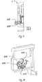
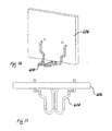
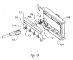
- Fig. 18 is a partially exploded view of an intelligent patch panel further showing a plug for insertion into the intelligent patch panel;
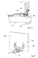
- Fig. 19 is a side sectional view of a plug inserted into the intelligent patch panel.
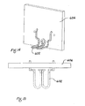
- Fig. 20 is a front isometric view of the plug contact mated to the intelligent patch panel contacts.
- the present invention is directed to methods and systems for monitoring, documenting, and guiding patch cord changes in a patch field of a communications network.
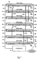
- Fig. 1 is a schematic diagram of seven exemplary modular, intelligent patch panels 202(a-g). Each intelligent patch panel 202 is based upon a modularly scalable, distributed architecture. Each patch panel 202 may include a pair of network connection ports 220 that allow the respective patch panels to be interconnected in a daisy-chain configuration to a network connection 210 using daisy-chain network cables 208 (e.g., relatively short spans of 4-pair network cable terminated in conventional RJ-45 terminators).
- Network connection 210 may provide network connectivity to each patch panel in the daisy-chain and may thereby provide each patch panel in the daisy-chain with connectivity to a remote Network Management System (NMS).
- NMS Network Management System
- each patch panel 202 may include a pair of power sharing ports 218 that allow the patch panels to be interconnected in a daisy-chain configuration to a single power supply 222 using daisy-chain power cables 216 (e.g., relatively short spans of DC or AC electrical power cabling with appropriate connectors).
- daisy-chain power cables 216 e.g., relatively short spans of DC or AC electrical power cabling with appropriate connectors.
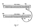
- Fig. 2 is a schematic diagram depicting an exchange of out-of-band messages between an intelligent patch panel 302(a) labeled "patch panel X" and an intelligent patch panel 302(b) labeled "patch panel Z.”
- the ports of patch panels according to the present invention may communicate connection information between each other. For example, as shown in Fig. 2 , patch panel port 304(a) associated with panel X may generate an outbound message "patch panel X/Port 21 to indicate that patch panel port 304(a) is the twenty-first port on patch panel X. As shown in Fig.
- port 304(b) associated with patch panel Z may generate an outbound message "patch panel Z/Port 17" to indicate that patch panel port 304(b) is the seventeenth port on patch panel Z. Messages may be coordinated as further explained below to inform the NMS of any changes to patch cord connections.
- Each patch panel port of the present invention is provided with contacts that enable intelligent patch panels according to the present invention to identify when patch cord plugs have been inserted into ports of the intelligent patch panels.
- Figs. 3-17 illustrate patch panel contacts and nine-wire patch cords that may be used in certain embodiments of the present invention.
- each patch panel port is provided with indicator lights which allow the intelligent patch panels to guide each step of the addition or removal of patch cords connected between patch panels. These indicator lights may be implemented as dual-color red and green LEDs, for example.
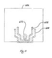
- Fig. 7 shows an example of a light pipe opening accommodating indicator lights. The use of contacts such as those shown and described below (with reference to Figs. 3-17 ) enables guided addition and removal processes, instant recognition of plug insertions and removals by the intelligent patch panels, and immediate communication of plug insertions and removals by intelligent patch panels to the NMS.
- a nine-wire patch cord 312 is to be connected between the twenty-first port 304(a) of a first intelligent patch panel 302(a) and the seventeenth port 304(b) of a second intelligent patch panel 302(b) as shown in Fig. 2 .
- the system orders the installation and lights designated port LEDs associated with both ports 302(a) and 304(b) solid green.
- plug 314(a) or 314(b) may be installed into its corresponding port.
- the plug 314(a) on one end of the patch cord 312 is installed into the port 304(a).
- the LED associated with that port is turned off and the NMS is notified (for example, via a connection between the patch panel and the NMS as illustrated in Fig. 1 ). If the plug is plugged into the wrong port, the LED associated with the wrong port flashes red until the plug is removed. The same procedure is followed for the installation of the other plug of the patch cord.
- the jack into which the first plug was installed transmits its identification information over the ninth wire of the patch cord 312 to the jack into which the second patch cord plug was installed.
- This communication is preferably accomplished via an out-of-band communication on the ninth wire of a nine-wire patch cord 312.
- the intelligent patch panel into which the second patch cord was installed then transmits the identification information of both connected ports to the NMS.
- a patch cord removal process is initiated when the system orders the removal of the patch cord and LEDs associated with the designated ports on each end of the patch cord to be removed both flash green.
- the plug on one end is removed and, if it is one of the designated ports, the LED associated with the port from which the plug was removed is turned off and the NMS is notified of the removal of the plug.
- the LED associated with the incorrect port lights solid red to indicate that the plug is to be replaced.
- an identification transmission similar to the above, is made to ensure the correct plug was installed.
- red LEDs of the jack or jacks associated with the problem will be lit solid or flashing red.
- the NMS will be notified and any in-process installation or removal procedure will be halted until the problem is rectified.
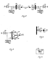
- Figs. 3-5 illustrate contact assemblies that may be used in some embodiments of the present invention.
- ninth-wire panel contacts 420 and 421 (each having respective contact portions designated “a” and “b") are provided in panels 430 and 431.
- the panel contacts in combination with connectivity detectors 460 and 461 and transceivers 400 and 401, allow the intelligent patch panels to detect the insertion of ninth-wire cord contacts 415 or 416 of a nine-wire patch cord 410 and to communicate necessary information between intelligent patch panels as described above.
- Figs. 4-6 illustrate one embodiment of a contact assembly 520, having three contact portions 520a, 520b, and 520c installed in a panel 530.
- a ninth wire contact 515 of a nine-wire patch cord 510 is inserted between the contacts, thus completing a circuit and enabling the features described above.
- the ninth wire contact 515 may be provided with a hole or indentation 517 into which the overlapping sections of the portion 520a, 520b, and 520c may nestle.
- Figs. 7-17 illustrate another embodiment of contacts that may be used in the present invention.
- the embodiment of Figs. 7-17 comprises a contact area 600 that is positioned to contact ninth wire contacts of nine-wire patch cords.
- the contact area 600 houses upper and lower contacts 602 and 604, each of which is inserted into and makes electrical contact with a printed circuit board (PCB) as shown in Fig. 8.
- Fig. 8 shows a portion 606 of the PCB.
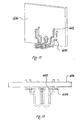
- the assembly may be provided in an intelligent patch panel cover 610 that is provided with light-pipe openings 612 at each port position. Proper tension to ensure normal contact force between the upper and lower contacts 602 and 604 and contacts on a plug may be maintained with the use of upper and lower spring loops 612 and 614 as shown in Fig. 10 .
- a contact such as a blade contact on the plug completes a circuit between the upper and lower contacts 602 and 604, which allows immediate detection of plug insertion.
- the connectivity detector circuitry may be provided on the PCB 606.
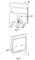
- Fig. 18 is a partially exploded view of a portion of an intelligent patch panel according to one embodiment having upper and lower contacts 702 and 704 installed therein.
- the contacts 702, 704 are mounted and electrically connected to the PCB 706, which is provided on a face plate 707.
- a section 709 of the panel (which may be a stamped metal panel) is shown.
- a panel cover 711 provided with light-pipe openings 712 and panel contact shrouds 713 is installed on the front face of the panel.
- a jack 715 is shown within the panel section 709.
- a plug 717 having a plug blade contact 719 is also shown.
- Contacts of the type shown in Figs. 7-20 offer a self-aligning contact interface area that can move left or right to allow panel contacts to align with plug contacts.
- the contact geometry and mounting location facilitate this alignment.
- the contacts are preferably made of pre-plated round wire which reduces or eliminates scrap, eliminates the need for stamping dies, provides good yield strength, and enables low-cost construction of the contacts.
- Loop dimensions of the upper and lower spring loops 612 (e.g., length and radius of the loops) can be changed to adjust contact normal force without changing the overall design of the contacts.
- patch cords according to other embodiments of the present invention are designed for use in optical communication networks or in other electrical communication networks that do not employ RJ-45 plugs and jacks.
- a system for documenting and guiding patch cord connections in a network comprising: a plurality of modular patch panels, each of said modular patch panels having a pair of network connection ports, a plurality of patch panel ports, and a pair of power sharing ports; wherein each of said patch panel ports is adapted to instantly detect the insertion of a patch cord plug into the patch panel port and each of said modular patch panels is adapted to immediately communicate information regarding the insertion of a patch cord plug to a network management system.
- each of said network connection ports is adapted to permit connection between modular patch panels to allow communication between modular patch panels.
- each of said network connection ports is adapted to allow connection between a modular patch panel and a network management system.
- each of said network connection ports is further adapted to allow connection and communication between a modular patch panel and a network management system.
- the system further comprises at least one indicator adjacent each of said patch panel ports, said at least one indicator adapted to immediately notify an installer of the correct or incorrect insertion of a patch cord plug into the adjacent patch panel port.
- the system further comprises at least one indicator adjacent each of said patch panel ports, said at least one indicator adapted to immediately notify an installer of the correct or incorrect removal of a patch cord plug from the adjacent patch panel port.
- each of said patch panel ports detects insertion or removal of a patch cord plug via an out-of-band connection with the patch cord plug.
- each of said patch panel ports has an upper contact and a lower contact, said upper contact and said lower contact being arranged such that a circuit is completed between the upper contact and the lower contact when a blade contact is positioned between the upper contact and the lower contact, the upper contact having a spring loop adapted to provide sufficient normal force to promote electrical connection between the upper contact and the blade contact.
- a system for documenting and guiding patch cord connections in a network comprising: a plurality of modular patch panels, each of said modular patch panels having a plurality of patch panel ports, each of said patch panel ports being provided with an associated pair of ninth-wire contacts, each of said contact pairs comprising an upper contact and a lower contact, said upper contact and said lower contact being arranged such that a circuit is completed between the upper contact and the lower contact when a blade contact is positioned between the upper contact and the lower contact, the upper contact having a spring loop adapted to provide sufficient normal force to promote electrical connection between the upper contact and the blade contact.
- said lower contact has a spring loop adapted to provide sufficient normal force to promote electrical connection between the lower contact and the blade contact.
- said upper contact and said lower contact are mounted and electrically connected to a printed circuit board which is provided on a face plate of the modular patch panel.
- system further comprises a panel cover having light-pipe openings adapted to allow an installer to view indicator lights.
- system further comprises a panel cover having panel contact shrouds.
- a system for documenting patch cord connections in a network wherein each of said patch cord connections is made with a nine-wire patch cord, said system comprising: a plurality of patch panel ports, each of said patch panel ports being provided with a pair of ninth-wire contacts, each of said ninth-wire contact pairs being adapted to transmit via an out-of-band communication on a ninth wire of a ninth wire patch cord, said out-of-band communication comprising identification information for the respective patch panel port; wherein each of said patch panel ports is adapted to instantly detect the insertion of a patch cord plug into the patch panel port and each of said modular patch panels is adapted to immediately communicate information regarding the insertion of a patch cord plug to a network management system.
Abstract
Description
- The present invention pertains to network cable management.
- Communications networks are growing in number and complexity. Monitoring network connections, including the management of patch panel connections, is an important task in network management. There is a desire for a patch panel management architecture that is reliable and scalable.
US 2002/0069277A1 describes a revision system for a network having a plurality of data ports, pairs of the data ports being connectable by a patch cord, the revision system including a computer processor in communication with a scanner, the scanner capable of polling at least some of the data ports for determining status information therefrom. - The invention is defined in the appended claims.
- According to one embodiment of the present invention, a patch cord management system supports patch cord management in communications networks having a cross-connect configuration. Methods and apparatuses are provided for monitoring and reporting cable connectivity such as intelligent patch panel port-level connectivity in real-time.
For the intelligent patch panel system example, the approach is based on a distributed architecture that may be modularly scalable, that eliminates the need for monitoring systems that continuously scan ninth wire connections, and that eliminates the need for complex cabling between patch panels and the monitoring systems. Each intelligent patch panel is the same as every other intelligent patch panel. Connectivity information can be determined instantly and communicated via an Ethernet link to a Network Management System (NMS) upon additions, removals, or changes to connections between intelligent patch panels. Polling delays and polling-related overhead is eliminated by supporting real-time monitoring of port connectivity at the port level. The approach is controlled by a multipurpose NMS. - Embodiments of the present invention comprise a network connection documentation system which starts the documentation process when a first patch cord is installed in a port of an intelligent patch panel and notifies the NMS of any change in the patch field in real time.
-
Fig. 1 is a front view of intelligent patch panels according to one embodiment of the present invention; -
Fig. 2 is a front view of two intelligent patch panels in a connection process; -
Fig. 3 is a diagram of a patch cord detection assembly according to one embodiment of the present invention; -
Figs. 4-6 are diagrams of a patch cord detection assembly according to another embodiment of the present invention; -
Figs. 7-17 illustrate patch cord detection contacts according to one embodiment of the present invention; -
Fig. 18 is a partially exploded view of an intelligent patch panel further showing a plug for insertion into the intelligent patch panel; -
Fig. 19 is a side sectional view of a plug inserted into the intelligent patch panel; and -
Fig. 20 is a front isometric view of the plug contact mated to the intelligent patch panel contacts. - The present invention is directed to methods and systems for monitoring, documenting, and guiding patch cord changes in a patch field of a communications network.
-
Fig. 1 is a schematic diagram of seven exemplary modular, intelligent patch panels 202(a-g). Eachintelligent patch panel 202 is based upon a modularly scalable, distributed architecture. Eachpatch panel 202 may include a pair ofnetwork connection ports 220 that allow the respective patch panels to be interconnected in a daisy-chain configuration to anetwork connection 210 using daisy-chain network cables 208 (e.g., relatively short spans of 4-pair network cable terminated in conventional RJ-45 terminators).Network connection 210 may provide network connectivity to each patch panel in the daisy-chain and may thereby provide each patch panel in the daisy-chain with connectivity to a remote Network Management System (NMS). Further, eachpatch panel 202 may include a pair ofpower sharing ports 218 that allow the patch panels to be interconnected in a daisy-chain configuration to asingle power supply 222 using daisy-chain power cables 216 (e.g., relatively short spans of DC or AC electrical power cabling with appropriate connectors). -
Fig. 2 is a schematic diagram depicting an exchange of out-of-band messages between an intelligent patch panel 302(a) labeled "patch panel X" and an intelligent patch panel 302(b) labeled "patch panel Z." The ports of patch panels according to the present invention may communicate connection information between each other. For example, as shown inFig. 2 , patch panel port 304(a) associated with panel X may generate an outbound message "patch panel X/Port 21 to indicate that patch panel port 304(a) is the twenty-first port on patch panel X. As shown inFig. 3 , port 304(b) associated with patch panel Z may generate an outbound message "patch panel Z/Port 17" to indicate that patch panel port 304(b) is the seventeenth port on patch panel Z. Messages may be coordinated as further explained below to inform the NMS of any changes to patch cord connections. - Each patch panel port of the present invention is provided with contacts that enable intelligent patch panels according to the present invention to identify when patch cord plugs have been inserted into ports of the intelligent patch panels.
Figs. 3-17 illustrate patch panel contacts and nine-wire patch cords that may be used in certain embodiments of the present invention. Further, each patch panel port is provided with indicator lights which allow the intelligent patch panels to guide each step of the addition or removal of patch cords connected between patch panels. These indicator lights may be implemented as dual-color red and green LEDs, for example.Fig. 7 shows an example of a light pipe opening accommodating indicator lights. The use of contacts such as those shown and described below (with reference toFigs. 3-17 ) enables guided addition and removal processes, instant recognition of plug insertions and removals by the intelligent patch panels, and immediate communication of plug insertions and removals by intelligent patch panels to the NMS. - Addition of a patch cord will now be described with reference to
Fig. 2 . In addition and removal processes according to the present invention, LEDs associated with patch panel ports are used as follows:On: Add a plug Flashing: Remove a plug Green: Normal operation Red: An error has been made. - In the illustrated patch cord installation process, a nine-
wire patch cord 312 is to be connected between the twenty-first port 304(a) of a first intelligent patch panel 302(a) and the seventeenth port 304(b) of a second intelligent patch panel 302(b) as shown inFig. 2 . The system orders the installation and lights designated port LEDs associated with both ports 302(a) and 304(b) solid green. Next, either plug 314(a) or 314(b) may be installed into its corresponding port. For example, the plug 314(a) on one end of thepatch cord 312 is installed into the port 304(a). If the plug 314(a) is plugged into one of the designated ports for the cord installation (e.g., port 304(a)), the LED associated with that port is turned off and the NMS is notified (for example, via a connection between the patch panel and the NMS as illustrated inFig. 1 ). If the plug is plugged into the wrong port, the LED associated with the wrong port flashes red until the plug is removed. The same procedure is followed for the installation of the other plug of the patch cord. - When both plugs are connected, the jack into which the first plug was installed transmits its identification information over the ninth wire of the
patch cord 312 to the jack into which the second patch cord plug was installed. This communication is preferably accomplished via an out-of-band communication on the ninth wire of a nine-wire patch cord 312. The intelligent patch panel into which the second patch cord was installed then transmits the identification information of both connected ports to the NMS. - A patch cord removal process is initiated when the system orders the removal of the patch cord and LEDs associated with the designated ports on each end of the patch cord to be removed both flash green. The plug on one end is removed and, if it is one of the designated ports, the LED associated with the port from which the plug was removed is turned off and the NMS is notified of the removal of the plug.
- If a plug is removed from an incorrect port, the LED associated with the incorrect port lights solid red to indicate that the plug is to be replaced. When the plug is replaced, an identification transmission, similar to the above, is made to ensure the correct plug was installed.
- When the plug at the second end of the patch cord is removed, a similar procedure is followed.
- If any change in the patch cord field is made which has not been ordered, red LEDs of the jack or jacks associated with the problem will be lit solid or flashing red. The NMS will be notified and any in-process installation or removal procedure will be halted until the problem is rectified.
-
Figs. 3-5 illustrate contact assemblies that may be used in some embodiments of the present invention. As shown inFig. 3 , ninth-wire panel contacts 420 and 421 (each having respective contact portions designated "a" and "b") are provided inpanels connectivity detectors transceivers wire cord contacts 415 or 416 of a nine-wire patch cord 410 and to communicate necessary information between intelligent patch panels as described above.Figs. 4-6 illustrate one embodiment of acontact assembly 520, having threecontact portions panel 530. Aninth wire contact 515 of a nine-wire patch cord 510 is inserted between the contacts, thus completing a circuit and enabling the features described above. Theninth wire contact 515 may be provided with a hole orindentation 517 into which the overlapping sections of theportion U.S. 2007/032124
, entitled "Systems and Methods for Detecting a Patch Cord End Connection". -
Figs. 7-17 illustrate another embodiment of contacts that may be used in the present invention. The embodiment ofFigs. 7-17 comprises a contact area 600 that is positioned to contact ninth wire contacts of nine-wire patch cords. The contact area 600 houses upper andlower contacts Fig. 8. Fig. 8 shows aportion 606 of the PCB. As shown inFig. 7 , the assembly may be provided in an intelligentpatch panel cover 610 that is provided with light-pipe openings 612 at each port position. Proper tension to ensure normal contact force between the upper andlower contacts lower spring loops Fig. 10 . - In the embodiments shown in
Figs. 7-20 , as in other embodiments, a contact such as a blade contact on the plug completes a circuit between the upper andlower contacts PCB 606. -
Fig. 18 is a partially exploded view of a portion of an intelligent patch panel according to one embodiment having upper andlower contacts contacts PCB 706, which is provided on a face plate 707. Asection 709 of the panel (which may be a stamped metal panel) is shown. apanel cover 711 provided with light-pipe openings 712 and panel contact shrouds 713 is installed on the front face of the panel. Ajack 715 is shown within thepanel section 709. Aplug 717 having aplug blade contact 719 is also shown. - Contacts of the type shown in
Figs. 7-20 offer a self-aligning contact interface area that can move left or right to allow panel contacts to align with plug contacts. The contact geometry and mounting location facilitate this alignment. The contacts are preferably made of pre-plated round wire which reduces or eliminates scrap, eliminates the need for stamping dies, provides good yield strength, and enables low-cost construction of the contacts. Loop dimensions of the upper and lower spring loops 612 (e.g., length and radius of the loops) can be changed to adjust contact normal force without changing the overall design of the contacts. - The principles of the present invention may be applied to other specific systems. For example, patch cords according to other embodiments of the present invention are designed for use in optical communication networks or in other electrical communication networks that do not employ RJ-45 plugs and jacks.
- While the present invention has been described with reference to one or more particular embodiments, those skilled in the art will recognize that many changes may be made thereto without departing from the scope of the present invention. Each of these embodiments and obvious variations thereof is contemplated as falling within the scope of the claimed invention, which is set forth in the following claims.
- In a first example there is provided a system for documenting and guiding patch cord connections in a network comprising: a plurality of modular patch panels, each of said modular patch panels having a pair of network connection ports, a plurality of patch panel ports, and a pair of power sharing ports; wherein each of said patch panel ports is adapted to instantly detect the insertion of a patch cord plug into the patch panel port and each of said modular patch panels is adapted to immediately communicate information regarding the insertion of a patch cord plug to a network management system.
- Optionally, each of said network connection ports is adapted to permit connection between modular patch panels to allow communication between modular patch panels.
- Optionally, each of said network connection ports is adapted to allow connection between a modular patch panel and a network management system.
- Optionally, each of said network connection ports is further adapted to allow connection and communication between a modular patch panel and a network management system.
- Optionally, the system further comprises at least one indicator adjacent each of said patch panel ports, said at least one indicator adapted to immediately notify an installer of the correct or incorrect insertion of a patch cord plug into the adjacent patch panel port.
- Optionally, the system further comprises at least one indicator adjacent each of said patch panel ports, said at least one indicator adapted to immediately notify an installer of the correct or incorrect removal of a patch cord plug from the adjacent patch panel port.
- Optionally, each of said patch panel ports detects insertion or removal of a patch cord plug via an out-of-band connection with the patch cord plug.
- Optionally, each of said patch panel ports has an upper contact and a lower contact, said upper contact and said lower contact being arranged such that a circuit is completed between the upper contact and the lower contact when a blade contact is positioned between the upper contact and the lower contact, the upper contact having a spring loop adapted to provide sufficient normal force to promote electrical connection between the upper contact and the blade contact.
- In a second example there is provided a system for documenting and guiding patch cord connections in a network comprising: a plurality of modular patch panels, each of said modular patch panels having a plurality of patch panel ports, each of said patch panel ports being provided with an associated pair of ninth-wire contacts, each of said contact pairs comprising an upper contact and a lower contact, said upper contact and said lower contact being arranged such that a circuit is completed between the upper contact and the lower contact when a blade contact is positioned between the upper contact and the lower contact, the upper contact having a spring loop adapted to provide sufficient normal force to promote electrical connection between the upper contact and the blade contact.
- Optionally, said lower contact has a spring loop adapted to provide sufficient normal force to promote electrical connection between the lower contact and the blade contact.
- Optionally, said upper contact and said lower contact are mounted and electrically connected to a printed circuit board which is provided on a face plate of the modular patch panel.
- Optionally, the system further comprises a panel cover having light-pipe openings adapted to allow an installer to view indicator lights.
- Optionally, the system further comprises a panel cover having panel contact shrouds.
- In a third example there is provided a system for documenting patch cord connections in a network wherein each of said patch cord connections is made with a nine-wire patch cord, said system comprising: a plurality of patch panel ports, each of said patch panel ports being provided with a pair of ninth-wire contacts, each of said ninth-wire contact pairs being adapted to transmit via an out-of-band communication on a ninth wire of a ninth wire patch cord, said out-of-band communication comprising identification information for the respective patch panel port; wherein each of said patch panel ports is adapted to instantly detect the insertion of a patch cord plug into the patch panel port and each of said modular patch panels is adapted to immediately communicate information regarding the insertion of a patch cord plug to a network management system.
Claims (9)
- A modular patch panel (202) for use in a system for documenting and guiding patch cord connections comprising
a port (220)
wherein the port (220) comprises an upper contact (602) and a lower contact (604), the upper and lower contacts being arranged such that a circuit is completed between the upper contact (602) and lower contact (604) when a blade contact (719) is positioned between the upper contact (602) and the lower contact (604) and wherein the upper and lower contacts offer a self-aligning contact interface area; and
wherein the modular patch panel (202) is adapted to communicate with a network management system via an out-of-band communication through the blade contact (719) positioned between the upper and lower contacts (602, 604). - The modular patch panel (202) of claim 1 wherein at least one of the upper contact (602) and lower contact (604) has a spring loop (612) adapted to provide sufficient normal force to promote electrical connection between the at least one upper contact (602) and lower contact (604) and the blade contact (719).
- The modular patch panel (202) of claim 2 wherein said upper contact (602) and said lower contact (604) are mounted and electrically connected to a printed circuit board (606) which is provided on a face plate of the modular patch panel (202).
- The modular patch panel (202) of claim 1 wherein the upper and lower contacts (602, 604) are made of pre-plated round wire.
- The modular patch panel (202) of claim 1 further comprising a panel cover (610) having light-pipe openings (612) adapted to allow an installer to view indicator lights.
- The modular patch panel (202) of claim 1 further comprising a panel cover (610) having panel contact shrouds (713).
- The modular patch panel (202) of claim 1, for use in a system for patch cord documentation and revision utilizing a patch cord (410) with a ninth wire and a connector with a ninth wire pin (415) configured for out-of-band transmissions wherein
the port (220) is in the form of an opening, the opening containing a plurality of contacts configured for data communication; and the upper and lower contacts (602, 604) each comprise a conductor forming two adjoining "U" shapes,
wherein the ninth wire pin (415) is configured to simultaneously engage the upper and lower contacts (602, 604) by sliding between the adjoining "U" shapes of both the upper and lower contacts (602, 604) and thus completing an electrical circuit between the upper and lower contacts (602, 604), the contacts being electrically isolated when the ninth wire pin (415) is not engaged therewith. - The modular patch panel (202) of claim 7 further comprising light pipe openings (612).
- The modular patch panel (202) of claim 8 wherein the light pipe openings (612) and upper and lower contacts (602, 604) are located on a removable panel cover (610).
Applications Claiming Priority (3)
| Application Number | Priority Date | Filing Date | Title |
|---|---|---|---|
| US77326406P | 2006-02-14 | 2006-02-14 | |
| US11/673,927 US7488206B2 (en) | 2006-02-14 | 2007-02-12 | Method and apparatus for patch panel patch cord documentation and revision |
| EP07250598A EP1819176B1 (en) | 2006-02-14 | 2007-02-14 | Apparatus for patch cord documentation and revision |
Related Parent Applications (1)
| Application Number | Title | Priority Date | Filing Date |
|---|---|---|---|
| EP07250598.5 Division | 2007-02-14 |
Publications (3)
| Publication Number | Publication Date |
|---|---|
| EP2265034A2 EP2265034A2 (en) | 2010-12-22 |
| EP2265034A3 EP2265034A3 (en) | 2011-01-05 |
| EP2265034B1 true EP2265034B1 (en) | 2012-05-30 |
Family
ID=38042643
Family Applications (2)
| Application Number | Title | Priority Date | Filing Date |
|---|---|---|---|
| EP07250598A Not-in-force EP1819176B1 (en) | 2006-02-14 | 2007-02-14 | Apparatus for patch cord documentation and revision |
| EP10176239A Not-in-force EP2265034B1 (en) | 2006-02-14 | 2007-02-14 | Apparatus for patch panel patch cord documentation and revision |
Family Applications Before (1)
| Application Number | Title | Priority Date | Filing Date |
|---|---|---|---|
| EP07250598A Not-in-force EP1819176B1 (en) | 2006-02-14 | 2007-02-14 | Apparatus for patch cord documentation and revision |
Country Status (5)
| Country | Link |
|---|---|
| US (3) | US7488206B2 (en) |
| EP (2) | EP1819176B1 (en) |
| JP (1) | JP4972426B2 (en) |
| CN (1) | CN101030888B (en) |
| AT (1) | ATE533309T1 (en) |
Families Citing this family (58)
| Publication number | Priority date | Publication date | Assignee | Title |
|---|---|---|---|---|
| US20050141431A1 (en) | 2003-08-06 | 2005-06-30 | Caveney Jack E. | Network managed device installation and provisioning technique |
| EP1743490B1 (en) * | 2004-05-03 | 2011-09-14 | Panduit Corporation | Powered patch panel |
| EP1734692A1 (en) * | 2005-06-14 | 2006-12-20 | Panduit Corporation | Method and apparatus for monitoring physical network topology information |
| EP1922786A1 (en) | 2005-08-08 | 2008-05-21 | Panduit Corp. | Systems and methods for detecting a patch cord end connection |
| US7234944B2 (en) * | 2005-08-26 | 2007-06-26 | Panduit Corp. | Patch field documentation and revision systems |
| US7978845B2 (en) | 2005-09-28 | 2011-07-12 | Panduit Corp. | Powered patch panel |
| US7479032B2 (en) * | 2006-10-10 | 2009-01-20 | Adc Gmbh | Upgradeable telecommunications patch panel and method of upgrading same |
| US7715679B2 (en) | 2007-05-07 | 2010-05-11 | Adc Telecommunications, Inc. | Fiber optic enclosure with external cable spool |
| US7756379B2 (en) | 2007-08-06 | 2010-07-13 | Adc Telecommunications, Inc. | Fiber optic enclosure with internal cable spool |
| US8910234B2 (en) * | 2007-08-21 | 2014-12-09 | Schneider Electric It Corporation | System and method for enforcing network device provisioning policy |
| US7674126B2 (en) * | 2007-10-08 | 2010-03-09 | The Siemen Company | Contacts for use in monitoring connection patterns in data ports |
| US8263867B2 (en) | 2008-01-07 | 2012-09-11 | Chatsworth Products, Inc. | Cable management accessories |
| SE535066C2 (en) | 2008-01-07 | 2012-04-03 | Chatsworth Prod Inc | Vertical cable management device |
| WO2009089008A2 (en) | 2008-01-07 | 2009-07-16 | Corning Cable Systems Llc | Apparatus and method for organizing cables in a cabinet |
| WO2009105632A1 (en) * | 2008-02-21 | 2009-08-27 | Panduit Corp. | Intelligent inter-connect and cross-connect patching system |
| WO2010042589A1 (en) * | 2008-10-07 | 2010-04-15 | Molex Incorporated | System for and method of network asset identification |
| US8588050B2 (en) * | 2008-11-12 | 2013-11-19 | Panduit Corp. | Intelligent patching system |
| US8306935B2 (en) * | 2008-12-22 | 2012-11-06 | Panduit Corp. | Physical infrastructure management system |
| US8753142B2 (en) * | 2009-03-09 | 2014-06-17 | Commscope, Inc. Of North Carolina | Methods of converting patching system to intelligent patching system and related shelf units |
| US7896692B2 (en) * | 2009-05-15 | 2011-03-01 | Leviton Manufacturing Co., Inc. | Method of improving isolation between circuits on a printed circuit board |
| US8994547B2 (en) | 2009-08-21 | 2015-03-31 | Commscope, Inc. Of North Carolina | Systems for automatically tracking patching connections to network devices using a separate control channel and related patching equipment and methods |
| US9538262B2 (en) | 2009-08-21 | 2017-01-03 | Commscope, Inc. Of North Carolina | Systems, equipment and methods for automatically tracking cable connections and for identifying work area devices and related methods of operating communications networks |
| US9261654B2 (en) * | 2009-10-13 | 2016-02-16 | Leviton Manufacturing Co., Inc. | Fiber optic adapter plates with integrated fiber optic adapters |
| US8596882B2 (en) | 2009-10-16 | 2013-12-03 | Adc Telecommunications, Inc. | Managed connectivity in fiber optic systems and methods thereof |
| ES2608689T3 (en) | 2009-10-16 | 2017-04-12 | Adc Telecommunications, Inc. | Directed connectivity in electrical systems and their methods |
| JP2013508918A (en) | 2009-10-19 | 2013-03-07 | エーディーシー テレコミュニケーションズ,インコーポレイティド | Managed electrical connection system |
| TWI436534B (en) | 2010-01-29 | 2014-05-01 | Surtec Ind Inc | Intelligent structured cabling system and jack |
| US9007206B2 (en) * | 2010-01-29 | 2015-04-14 | Surtec Industries, Inc. | Patch panel and intelligent structured cabling system |
| EP2534846B1 (en) | 2010-02-12 | 2018-07-25 | ADC Telecommunications, Inc. | Communications bladed panel system |
| ES2679275T3 (en) | 2010-02-12 | 2018-08-23 | Adc Telecommunications, Inc. | Managed fiber connectivity systems |
| US20110266980A1 (en) * | 2010-04-30 | 2011-11-03 | Research In Motion Limited | Lighted Port |
| CN105807379B (en) | 2010-06-23 | 2019-06-18 | Adc电信公司 | Telecommunication assembly |
| US8696369B2 (en) | 2010-09-09 | 2014-04-15 | Adc Telecommunications, Inc. | Electrical plug with main contacts and retractable secondary contacts |
| US8992261B2 (en) | 2010-10-22 | 2015-03-31 | Adc Telecommunications, Inc. | Single-piece plug nose with multiple contact sets |
| US8715012B2 (en) | 2011-04-15 | 2014-05-06 | Adc Telecommunications, Inc. | Managed electrical connectivity systems |
| US20120270436A1 (en) * | 2011-04-19 | 2012-10-25 | Blythe Stephen P | Identifying individual copper network cables on a patch panel |
| US9064022B2 (en) | 2011-05-17 | 2015-06-23 | Adc Telecommunications, Inc. | Component identification and tracking system for telecommunication networks |
| CA2877896C (en) | 2011-06-24 | 2020-07-21 | Adc Telecommunications, Inc. | Fiber termination enclosure with modular plate assemblies |
| TWI450531B (en) * | 2011-08-22 | 2014-08-21 | Edgecore Networks Corp | Network device and port function setting method thereof |
| US9172624B1 (en) | 2011-12-23 | 2015-10-27 | Google Inc. | Determining physical connectivity of data center devices |
| US9093796B2 (en) | 2012-07-06 | 2015-07-28 | Adc Telecommunications, Inc. | Managed electrical connectivity systems |
| WO2014022781A1 (en) | 2012-08-03 | 2014-02-06 | Joseph Christopher Coffey | Managed fiber connectivity systems |
| US9203198B2 (en) | 2012-09-28 | 2015-12-01 | Commscope Technologies Llc | Low profile faceplate having managed connectivity |
| US9130318B2 (en) | 2012-11-16 | 2015-09-08 | Tyco Electronics Uk Ltd. | Localized reading of RFID tags located on multiple sides of a port from a single side using RFID coupling circuit and portable RFID reader |
| EP2936228A1 (en) | 2012-12-19 | 2015-10-28 | Tyco Electronics Raychem BVBA | Distribution device with incrementally added splitters |
| US9379501B2 (en) | 2013-02-05 | 2016-06-28 | Commscope Technologies Llc | Optical assemblies with managed connectivity |
| US9423570B2 (en) | 2013-02-05 | 2016-08-23 | Commscope Technologies Llc | Optical assemblies with managed connectivity |
| US9285552B2 (en) | 2013-02-05 | 2016-03-15 | Commscope Technologies Llc | Optical assemblies with managed connectivity |
| KR102064014B1 (en) * | 2013-09-26 | 2020-01-08 | 엘에스전선 주식회사 | Patch Cord, Patch Panel And Management System Having The Same |
| WO2015148840A1 (en) | 2014-03-26 | 2015-10-01 | Tyco Electronics Corporation | Optical adapter module with managed connectivity |
| AU2015269194A1 (en) | 2014-06-05 | 2016-12-15 | Chatsworth Products, Inc. | Electrical receptacle with locking feature |
| CN106034090B (en) * | 2015-03-20 | 2019-05-31 | 联想(北京)有限公司 | Information processing method and interchanger |
| CN107210744B (en) * | 2015-04-29 | 2021-07-30 | 惠普发展公司有限责任合伙企业 | Connector element information detection |
| KR101701708B1 (en) * | 2016-07-25 | 2017-02-03 | 주식회사 체크올 | Led lan cable connecter capable of transmitting high rate data and led lan cable capable of transmitting high rate data and led lan cable capabl system capable of transmitting high rate data |
| US10659852B2 (en) | 2017-07-20 | 2020-05-19 | Hewlett-Packard Development Company, L.P. | Connector element information detections |
| US10547145B2 (en) | 2018-02-05 | 2020-01-28 | Chatworth Products, Inc. | Electric receptacle with locking feature |
| US10164375B1 (en) * | 2018-04-29 | 2018-12-25 | Cheng Uei Precision Industry Co., Ltd. | Plug connector |
| CN110285848B (en) * | 2019-07-11 | 2024-02-20 | 北京市水科学技术研究院 | Engineering safety monitoring line concentration device and engineering safety monitoring manual measuring and reading system |
Family Cites Families (152)
| Publication number | Priority date | Publication date | Assignee | Title |
|---|---|---|---|---|
| US3052842A (en) | 1959-10-15 | 1962-09-04 | Lockheed Aircraft Corp | Patchcord connection aid and checking system |
| US3573792A (en) | 1968-11-12 | 1971-04-06 | Us Navy | Universal display panel |
| US3573789A (en) | 1968-12-13 | 1971-04-06 | Ibm | Method and apparatus for increasing image resolution |
| US3914561A (en) | 1971-12-08 | 1975-10-21 | American Telephone & Telegraph | Apparatus and method for tracing jumpers in a main distributing frame |
| US4018997A (en) | 1974-05-10 | 1977-04-19 | Amp Incorporated | Pluggable key set telephone cross connect device |
| CA1012270A (en) | 1974-06-19 | 1977-06-14 | Arie Verhagen | Modular interchange termination system |
| US4072827A (en) | 1976-09-15 | 1978-02-07 | Oman Robert C | Telephone patching apparatus |
| US4096359A (en) | 1976-10-12 | 1978-06-20 | International Standard Electric Corporation | Key telephone system interconnection apparatus |
| US4196316A (en) | 1977-09-13 | 1980-04-01 | Bell Telephone Laboratories, Incorporated | Program controlled communication system having individually rearrangeable line selection |
| JPS5895927A (en) | 1981-12-02 | 1983-06-07 | 三菱電機株式会社 | Protecting relay system |
| US4673246A (en) | 1984-08-24 | 1987-06-16 | Pacific Bell | Patch unit for fiber optic distribution network |
| KR870011719A (en) | 1986-05-28 | 1987-12-26 | 쓰지 하루오 | Connection device |
| US4773867A (en) | 1986-07-02 | 1988-09-27 | Amp Incorporated | Premise distribution cross connect apparatus |
| JPS63139499A (en) | 1986-12-02 | 1988-06-11 | Toshiba Corp | Port connection system for electronic exchange |
| US4901004A (en) | 1988-12-09 | 1990-02-13 | King Fred N | Apparatus and method for mapping the connectivity of communications systems with multiple communications paths |
| US4937825A (en) | 1988-06-15 | 1990-06-26 | International Business Machines | Method and apparatus for diagnosing problems in data communication networks |
| JPH0221683A (en) | 1988-07-08 | 1990-01-24 | Mitsubishi Electric Corp | Semiconductor laser device |
| US5111408A (en) | 1988-10-19 | 1992-05-05 | Hewlett-Packard Company | Digital image documentation system |
| US5037167A (en) | 1989-05-01 | 1991-08-06 | Alcatel Na, Inc. | Electrical and fiber optic cable control and management |
| US5107532A (en) | 1989-09-22 | 1992-04-21 | Cable Management International, Inc. | Automated documentation system for a communications network |
| US5006822A (en) | 1990-01-03 | 1991-04-09 | Prabhakara Reddy | Hybrid RF coupling device with integrated capacitors and resistors |
| US5069641A (en) | 1990-02-03 | 1991-12-03 | Murata Manufacturing Co., Ltd. | Modular jack |
| US5226120A (en) | 1990-05-21 | 1993-07-06 | Synoptics Communications, Inc. | Apparatus and method of monitoring the status of a local area network |
| US5170327A (en) | 1990-11-05 | 1992-12-08 | Adc Telecommunications, Inc. | Distal distribution frame module |
| IL97227A0 (en) | 1991-02-13 | 1992-05-25 | Bynet System Applic Ltd | Patching panel |
| US5145380A (en) | 1991-06-17 | 1992-09-08 | Homaco, Inc. | Patch panel |
| US5270658A (en) | 1991-08-19 | 1993-12-14 | Epstein Barry M | Means and method for testing and monitoring a circuit breaker panel assembly |
| US5204929A (en) | 1991-09-04 | 1993-04-20 | Reliance Comm/Tec Corporation | Fiber patch panel |
| US5487666A (en) | 1991-12-31 | 1996-01-30 | Digiovanni; Thomas H. | Schematic patch panel |
| US5233501A (en) | 1992-02-27 | 1993-08-03 | Telect, Inc. | Digital telecommunication network cross-connect module having a printed circuit board connected to jack switches |
| US5299956B1 (en) | 1992-03-23 | 1995-10-24 | Superior Modular Prod Inc | Low cross talk electrical connector system |
| US5483467A (en) | 1992-06-10 | 1996-01-09 | Rit Technologies, Ltd. | Patching panel scanner |
| CA2072380C (en) | 1992-06-25 | 2000-08-01 | Michel Bohbot | Circuit assemblies of printed circuit boards and telecommunications connectors |
| US5432484A (en) | 1992-08-20 | 1995-07-11 | Hubbell Incorporated | Connector for communication systems with cancelled crosstalk |
| US5222164A (en) | 1992-08-27 | 1993-06-22 | International Business Machines Corporation | Electrically isolated optical connector identification system |
| CA2081608C (en) | 1992-10-28 | 1998-05-05 | Joseph Octave Regis Morin | Distribution frame and optical connector holder combination |
| US5295869A (en) | 1992-12-18 | 1994-03-22 | The Siemon Company | Electrically balanced connector assembly |
| US5305405A (en) | 1993-02-25 | 1994-04-19 | Adc Telecommunications, Inc. | Patch cord |
| JP2949546B2 (en) * | 1993-03-02 | 1999-09-13 | 富士通電装株式会社 | Wiring connection device and wiring connection method |
| JP3054899B2 (en) * | 1993-03-02 | 2000-06-19 | 富士通電装株式会社 | Wiring management method |
| US5269708A (en) | 1993-03-03 | 1993-12-14 | Adc Telecommunications, Inc. | Patch panel for high speed twisted pair |
| US5470244A (en) | 1993-10-05 | 1995-11-28 | Thomas & Betts Corporation | Electrical connector having reduced cross-talk |
| US5394503A (en) | 1993-10-08 | 1995-02-28 | Data Switch Corporation | Optical fiber connection monitoring apparatus, patch panel control system and method of using same |
| US5353367A (en) | 1993-11-29 | 1994-10-04 | Northern Telecom Limited | Distribution frame and optical connector holder combination |
| DE69330833T2 (en) | 1993-12-06 | 2002-03-28 | Agilent Technologies Inc | Job identification in a communication signaling network |
| US5432847A (en) | 1994-03-29 | 1995-07-11 | Telect, Inc. | Low frequency telecommunication digital network interface patch panel |
| FR2718546B1 (en) | 1994-04-08 | 1996-05-31 | Luc Lebeau | Computer link device between devices with heterogeneous communication systems, key relating to such a device. |
| US5684796A (en) | 1994-05-03 | 1997-11-04 | Bay Networks Group, Inc. | Method and apparatus for determining and maintaining agent topology information in a multi-segment network |
| US5550755A (en) | 1994-07-14 | 1996-08-27 | Martin; B. Morgan | Apparatus and method for patch recording and recall |
| DE9412794U1 (en) | 1994-08-09 | 1995-09-07 | Krone Ag | PCB for connectors |
| US5727055A (en) | 1995-05-17 | 1998-03-10 | Ies Technologies, Inc. | Information communication systems |
| IL110859A (en) | 1994-09-04 | 1999-12-31 | Rit Techn Ltd | Interconnection monitor system for telephone network |
| US5583874A (en) | 1994-12-07 | 1996-12-10 | Infonet Computer Systems, Inc. | 10Base-T portable link tester |
| US5562493A (en) * | 1994-12-16 | 1996-10-08 | The Whitaker | Network interface assembly and mounting frame |
| US5964609A (en) * | 1995-01-25 | 1999-10-12 | Haworth, Inc. | Modular communication cabling arrangement |
| US5532603A (en) | 1995-01-27 | 1996-07-02 | Fluke Corporation | Cross-talk measurement apparatus with near-end compensation |
| US5790041A (en) | 1995-02-14 | 1998-08-04 | Advanced Micro Devices, Inc. | Apparatus and method to display network connection status on a jack panel |
| US5618185A (en) | 1995-03-15 | 1997-04-08 | Hubbell Incorporated | Crosstalk noise reduction connector for telecommunication system |
| US5546282A (en) | 1995-05-02 | 1996-08-13 | Telect, Inc. | Telecommunication network digital cross-connect panels having insertable modules with printed circuit board mounted coaxial jack switches |
| US5754112A (en) | 1995-09-28 | 1998-05-19 | Sun Microsystems, Inc. | Power on, mated, and activity indicator for electronic devices including storage devices |
| WO1997019543A1 (en) | 1995-11-24 | 1997-05-29 | Voelker Technologies, Inc. | Electronic patching system for telecommunications devices |
| US5898837A (en) | 1996-02-23 | 1999-04-27 | Bay Networks, Inc. | Method and apparatus for monitoring a dedicated communications medium in a switched data network |
| WO1997032456A1 (en) | 1996-02-29 | 1997-09-04 | The Whitaker Corporation | Non-ohmic energy coupling for cross talk reduction |
| US5878030A (en) | 1996-06-19 | 1999-03-02 | Wandel & Goltermann Technologies, Inc. | Test access port for analyzing high-speed local area network switched environment |
| US5876240A (en) | 1997-04-01 | 1999-03-02 | The Whitaker Corp | Stacked electrical connector with visual indicators |
| US6067014A (en) | 1996-08-09 | 2000-05-23 | Wilson; Edwin P. | Cord tamper method and apparatus |
| US5847557A (en) | 1997-06-06 | 1998-12-08 | Fincher; William C. | Wire pair identification method |
| US5764043A (en) | 1996-12-20 | 1998-06-09 | Siecor Corporation | Traceable patch cord and connector assembly and method for locating patch cord ends |
| US5892756A (en) | 1997-01-28 | 1999-04-06 | Mtb Insights, Incorporated | Portable telecommunication network testing device |
| US5944535A (en) | 1997-02-04 | 1999-08-31 | Hubbell Incorporated | Interface panel system for networks |
| US5797764A (en) | 1997-02-12 | 1998-08-25 | Homaco, Inc. | Low return loss and low crosstalk telecommunications electric circuit |
| US5915993A (en) | 1997-02-27 | 1999-06-29 | Berg Technology, Inc. | Assembly containing a modular jack and a light emitting diode |
| US5923663A (en) | 1997-03-24 | 1999-07-13 | Compaq Computer Corporation | Method and apparatus for automatically detecting media connected to a network port |
| US5997358A (en) | 1997-09-02 | 1999-12-07 | Lucent Technologies Inc. | Electrical connector having time-delayed signal compensation |
| US6421322B1 (en) | 1997-11-17 | 2002-07-16 | Adc Telecommunications, Inc. | System and method for electronically identifying connections of a cross-connect system |
| US5971812A (en) | 1997-11-25 | 1999-10-26 | The Whitaker Corporation | Modular plug having a circuit board |
| US6041352A (en) | 1998-01-23 | 2000-03-21 | Hewlett-Packard Company | Response time measuring system and method for determining and isolating time delays within a network |
| US6094261A (en) | 1998-01-29 | 2000-07-25 | L-Com, Inc. | Method and apparatus for distinguishing fiber-optic cables |
| US5930119A (en) | 1998-02-26 | 1999-07-27 | Arizona Digital, Inc. | Backplane having reduced LC product |
| GB9807616D0 (en) | 1998-04-08 | 1998-06-10 | Weatherley Richard | Reduction of crosstalk in data transmission system |
| WO1999053643A1 (en) | 1998-04-13 | 1999-10-21 | Adc Telecommunications, Inc. | Test access and performance monitoring system and method for cross-connect communication networks |
| US6002331A (en) | 1998-07-20 | 1999-12-14 | Laor; Herzel | Method and apparatus for identifying and tracking connections of communication lines |
| US6371793B1 (en) | 1998-08-24 | 2002-04-16 | Panduit Corp. | Low crosstalk modular communication connector |
| US6229538B1 (en) | 1998-09-11 | 2001-05-08 | Compaq Computer Corporation | Port-centric graphic representations of network controllers |
| US6381283B1 (en) | 1998-10-07 | 2002-04-30 | Controlnet, Inc. | Integrated socket with chip carrier |
| US6086415A (en) | 1998-10-29 | 2000-07-11 | Hubbell Incorporated | High density modular patch panel |
| US6175865B1 (en) | 1998-11-12 | 2001-01-16 | Hewlett-Packard Company | Apparatus for automatically configuring network media connections |
| US5944595A (en) * | 1998-11-18 | 1999-08-31 | Prothro; Glenn J. | Feather picking device |
| US6437894B1 (en) | 1998-12-11 | 2002-08-20 | Fitel Usa Corp. | Fiber distribution shelf assembly for a fiber administration system having integral line tracing capabilities |
| US6434716B1 (en) | 1999-01-29 | 2002-08-13 | Psiber Data Systems Inc. | Network link tester device configured to selectively and automatically couple to a network transmit pair line or a node transmit pair line of a LAN port and determine available operational modes |
| US6078113A (en) | 1999-02-01 | 2000-06-20 | True; Mark E. | Power socket with illuminated plug blade slots |
| US6234830B1 (en) | 1999-02-10 | 2001-05-22 | Avaya Technology Corp. | Tracing interface module for patch cords in a telecommunications system |
| US6424710B1 (en) | 1999-02-10 | 2002-07-23 | Avaya Technology Corp. | Method and device for detecting the presence of a patch cord connector in a telecommunications patch system using passive detection sensors |
| US6522737B1 (en) | 1999-02-10 | 2003-02-18 | Avaya Technology Corp. | System and method of operation for a telecommunications patch system |
| US6350148B1 (en) | 1999-02-10 | 2002-02-26 | Avaya Technology Corp. | Method and device for detecting the presence of a patch cord connector in a telecommunications patch system |
| US6688910B1 (en) | 1999-02-10 | 2004-02-10 | Avaya Technology Corp. | System and method for automatic addressing of devices in a dedicated telecommunications system |
| US6285293B1 (en) | 1999-02-10 | 2001-09-04 | Avaya Technology Corp. | System and method for addressing and tracing patch cords in a dedicated telecommunications system |
| US6330307B1 (en) | 1999-02-10 | 2001-12-11 | Avaya Technology Corp. | Display panel overlay structure and method for tracing interface modules in a telecommunications patch system |
| US6483714B1 (en) | 1999-02-24 | 2002-11-19 | Kyocera Corporation | Multilayered wiring board |
| US6146192A (en) * | 1999-03-31 | 2000-11-14 | Adc Telecommunications, Inc. | Bulkhead connector system including angled adapter |
| DE60044042D1 (en) * | 1999-04-06 | 2010-04-29 | Itracs Corp | Data cable for monitoring connection patterns of data ports |
| SG74714A1 (en) | 1999-04-06 | 2001-08-21 | Cablesoft Inc | A system for monitoring connection pattern of data ports |
| US6431765B1 (en) * | 1999-06-11 | 2002-08-13 | Cisco Technology Inc. | Distributed network repeater module and method |
| US6370294B1 (en) | 1999-06-25 | 2002-04-09 | Adc Telecommunications, Inc. | Fiber optic circuit and module with switch |
| US6250968B1 (en) | 1999-07-14 | 2001-06-26 | Berg Technology, Inc. | Electrical connector system with cross-talk compensation |
| US6629269B1 (en) | 1999-07-23 | 2003-09-30 | Fluke Corporation | Apparatus and method for trouble-shooting desktop connectivity problems |
| US6089923A (en) | 1999-08-20 | 2000-07-18 | Adc Telecommunications, Inc. | Jack including crosstalk compensation for printed circuit board |
| US6499861B1 (en) | 1999-09-23 | 2002-12-31 | Avaya Technology Corp. | Illuminated patch cord connector ports for use in a telecommunications patch closet having patch cord tracing capabilities |
| US6222908B1 (en) | 1999-09-23 | 2001-04-24 | Avaya Technology Corp. | Method and device for identifying a specific patch cord connector as it is introduced into, or removed from, a telecommunications patch system |
| US6784802B1 (en) | 1999-11-04 | 2004-08-31 | Nordx/Cdt, Inc. | Real time monitoring of cable patch panel |
| US6577243B1 (en) | 1999-12-14 | 2003-06-10 | Alan J. Brown | Method and apparatus for tracing remote ends of networking cables |
| US6601097B1 (en) | 2000-01-10 | 2003-07-29 | International Business Machines Corporation | Method and system for determining the physical location of computers in a network by storing a room location and MAC address in the ethernet wall plate |
| US6243510B1 (en) | 2000-03-13 | 2001-06-05 | Apcon, Inc. | Electronically-controllable fiber optic patch panel |
| US6961675B2 (en) * | 2000-03-14 | 2005-11-01 | Itracs Corporation | System for monitoring connection pattern of data ports |
| US7110534B1 (en) * | 2000-07-27 | 2006-09-19 | Tyco Electronics Corporation | Terminal blocks and methods for making and breaking connections in a telecommunication conductor |
| US6379157B1 (en) | 2000-08-18 | 2002-04-30 | Leviton Manufacturing Co., Inc. | Communication connector with inductive compensation |
| US6456768B1 (en) | 2000-10-18 | 2002-09-24 | Fitel Usa Corp. | Optical fiber cable tracing system |
| EP1336275A2 (en) * | 2000-11-22 | 2003-08-20 | Panduit Corp. | Network revision system with local system ports |
| US6561827B2 (en) | 2000-12-18 | 2003-05-13 | Telefonaktiebolaget Lm Ericsson (Publ) | Apparatus for interconnecting multiple nodes |
| US6823063B2 (en) | 2001-04-27 | 2004-11-23 | Adc Telecommunications, Inc. | Cross-connect module and mount |
| DE10126351A1 (en) * | 2001-05-30 | 2002-12-12 | Ccs Technology Inc | Optical distribution device and fiber optic connection cable |
| US6704661B1 (en) | 2001-07-16 | 2004-03-09 | Therma-Wave, Inc. | Real time analysis of periodic structures on semiconductors |
| IL145103A (en) * | 2001-08-23 | 2010-05-17 | Rit Techn Ltd | High data rate interconnecting device |
| US20030061393A1 (en) * | 2001-09-21 | 2003-03-27 | Frank Steegmans | System and method for improving the management of information in networks by disposing machine accessible information tags along the interconnection means |
| US6461200B1 (en) * | 2001-12-11 | 2002-10-08 | Hon Hai Precision Ind. Co., Ltd. | Electrical connector assembly |
| US6714698B2 (en) | 2002-01-11 | 2004-03-30 | Adc Telecommunications, Inc. | System and method for programming and controlling a fiber optic circuit and module with switch |
| US6990592B2 (en) * | 2002-02-08 | 2006-01-24 | Enterasys Networks, Inc. | Controlling concurrent usage of network resources by multiple users at an entry point to a communications network based on identities of the users |
| US6937157B1 (en) * | 2002-05-13 | 2005-08-30 | Turnstone Systems, Inc. | Smart cable for design of high density metallic cross connect systems |
| US7005861B1 (en) | 2002-06-07 | 2006-02-28 | Marvell International Ltd. | Cable tester |
| US6802735B2 (en) | 2002-06-18 | 2004-10-12 | Tyco Electronics Corporation | Receptacle and plug interconnect module with integral sensor contacts |
| US6750643B2 (en) | 2002-08-05 | 2004-06-15 | Richard Hwang | Group wiring patching system and method for wire pair identification |
| US6898368B2 (en) | 2002-09-13 | 2005-05-24 | Fitel Usa Corp. | Adapter systems for dynamically updating information related to a network and methods for developing the adapter systems |
| US20040052471A1 (en) * | 2002-09-13 | 2004-03-18 | Fitel Usa Corp. | Connector systems for dynamically updating information related to a network and methods for developing the connector systems |
| GB2393549B (en) * | 2002-09-25 | 2006-05-31 | Cormant Technologies Inc | Cabling system |
| US6641443B1 (en) * | 2002-09-27 | 2003-11-04 | Leviton Manufacturing Co., Inc. | Electrical connector jack |
| US6875060B2 (en) * | 2002-10-21 | 2005-04-05 | Adc Telecommunications, Inc. | High density patching system |
| US6796847B2 (en) * | 2002-10-21 | 2004-09-28 | Hubbell Incorporated | Electrical connector for telecommunications applications |
| US6626697B1 (en) | 2002-11-07 | 2003-09-30 | Tyco Electronics Corp. | Network connection sensing assembly |
| EP1563573A4 (en) * | 2002-11-20 | 2009-07-15 | Siemon Co | Apparatus for crosstalk compensation in a telecommunications connector |
| US6857897B2 (en) | 2003-04-29 | 2005-02-22 | Hewlett-Packard Development Company, L.P. | Remote cable assist |
| US6871156B2 (en) | 2003-04-30 | 2005-03-22 | The Boeing Company | Smart connector patch panel |
| US6882140B2 (en) * | 2003-06-10 | 2005-04-19 | Tyco Electronics Corporation | Network connection sensing assembly |
| GB2406447B (en) * | 2003-09-26 | 2006-06-21 | Hellermanntyton Data Ltd | Structured cabling system and patching method |
| WO2005043937A2 (en) * | 2003-10-23 | 2005-05-12 | Panduit Corporation | System to guide and monitor the installation and revision of network cabling of an active jack network system |
| EP1695419A4 (en) * | 2003-11-21 | 2008-02-20 | Leviton Manufacturing Co | Patch panel with crosstalk reduction system and method |
| US7118414B2 (en) * | 2004-01-22 | 2006-10-10 | Northstar Systems, Inc. | Computer input/output connector assembly |
| US7038918B2 (en) * | 2004-03-03 | 2006-05-02 | Hubbell Incorporated | Midspan patch panel with compensation circuit for data terminal equipment, power insertion and data collection |
| US20050224585A1 (en) * | 2004-04-02 | 2005-10-13 | Durrant Richard C E | Radio frequency identification of a connector by a patch panel or other similar structure |
| US7066770B2 (en) * | 2004-04-27 | 2006-06-27 | Tyco Electronics Corporation | Interface adapter module |
| JP4790722B2 (en) * | 2004-11-03 | 2011-10-12 | パンドウィット・コーポレーション | Patch Panel Documentation for Patch Panel and Methods and Equipment for Revision |
| EP1734692A1 (en) * | 2005-06-14 | 2006-12-20 | Panduit Corporation | Method and apparatus for monitoring physical network topology information |
| US7044779B1 (en) * | 2005-06-21 | 2006-05-16 | Lankom Electronics Co., Ltd. | Electronic connector socket |
-
2007
- 2007-02-12 US US11/673,927 patent/US7488206B2/en active Active
- 2007-02-13 JP JP2007032377A patent/JP4972426B2/en active Active
- 2007-02-14 EP EP07250598A patent/EP1819176B1/en not_active Not-in-force
- 2007-02-14 AT AT07250598T patent/ATE533309T1/en active
- 2007-02-14 EP EP10176239A patent/EP2265034B1/en not_active Not-in-force
- 2007-02-14 CN CN200710084070.XA patent/CN101030888B/en not_active Expired - Fee Related
-
2008
- 2008-01-04 US US11/969,353 patent/US7534137B2/en active Active
-
2009
- 2009-05-18 US US12/467,862 patent/US7959460B2/en not_active Expired - Fee Related
Also Published As
| Publication number | Publication date |
|---|---|
| US7959460B2 (en) | 2011-06-14 |
| EP1819176B1 (en) | 2011-11-09 |
| US20070207666A1 (en) | 2007-09-06 |
| US7488206B2 (en) | 2009-02-10 |
| EP2265034A2 (en) | 2010-12-22 |
| US20080102693A1 (en) | 2008-05-01 |
| EP2265034A3 (en) | 2011-01-05 |
| JP2007267372A (en) | 2007-10-11 |
| US7534137B2 (en) | 2009-05-19 |
| CN101030888B (en) | 2012-05-09 |
| ATE533309T1 (en) | 2011-11-15 |
| CN101030888A (en) | 2007-09-05 |
| JP4972426B2 (en) | 2012-07-11 |
| US20090227140A1 (en) | 2009-09-10 |
| EP1819176A1 (en) | 2007-08-15 |
Similar Documents
| Publication | Publication Date | Title |
|---|---|---|
| EP2265034B1 (en) | Apparatus for patch panel patch cord documentation and revision | |
| US9866458B2 (en) | Intelligent inter-connect and cross-connect patching system | |
| US9838761B2 (en) | Intelligent patching system | |
| CN102106157B (en) | System and method for monitoring physical layer connectivity | |
| AU2010284185B2 (en) | Systems for automatically tracking patching connections to network devices using a separate control channel and related patching equipment and methods | |
| EP2206355B1 (en) | Communication port identification system | |
| US9007206B2 (en) | Patch panel and intelligent structured cabling system | |
| US6442032B1 (en) | Ethernet switch module and system | |
| KR102418183B1 (en) | Patch panel system with network monitoring function, and communication cable management systems using the same |
Legal Events
| Date | Code | Title | Description |
|---|---|---|---|
| PUAI | Public reference made under article 153(3) epc to a published international application that has entered the european phase |
Free format text: ORIGINAL CODE: 0009012 |
|
| PUAL | Search report despatched |
Free format text: ORIGINAL CODE: 0009013 |
|
| AC | Divisional application: reference to earlier application |
Ref document number: 1819176 Country of ref document: EP Kind code of ref document: P |
|
| AK | Designated contracting states |
Kind code of ref document: A2 Designated state(s): AT BE BG CH CY CZ DE DK EE ES FI FR GB GR HU IE IS IT LI LT LU LV MC NL PL PT RO SE SI SK TR |
|
| AK | Designated contracting states |
Kind code of ref document: A3 Designated state(s): AT BE BG CH CY CZ DE DK EE ES FI FR GB GR HU IE IS IT LI LT LU LV MC NL PL PT RO SE SI SK TR |
|
| 17P | Request for examination filed |
Effective date: 20110705 |
|
| GRAP | Despatch of communication of intention to grant a patent |
Free format text: ORIGINAL CODE: EPIDOSNIGR1 |
|
| RTI1 | Title (correction) |
Free format text: APPARATUS FOR PATCH PANEL PATCH CORD DOCUMENTATION AND REVISION |
|
| GRAS | Grant fee paid |
Free format text: ORIGINAL CODE: EPIDOSNIGR3 |
|
| GRAA | (expected) grant |
Free format text: ORIGINAL CODE: 0009210 |
|
| AC | Divisional application: reference to earlier application |
Ref document number: 1819176 Country of ref document: EP Kind code of ref document: P |
|
| AK | Designated contracting states |
Kind code of ref document: B1 Designated state(s): AT BE BG CH CY CZ DE DK EE ES FI FR GB GR HU IE IS IT LI LT LU LV MC NL PL PT RO SE SI SK TR |
|
| REG | Reference to a national code |
Ref country code: GB Ref legal event code: FG4D |
|
| REG | Reference to a national code |
Ref country code: CH Ref legal event code: EP |
|
| REG | Reference to a national code |
Ref country code: AT Ref legal event code: REF Ref document number: 560530 Country of ref document: AT Kind code of ref document: T Effective date: 20120615 |
|
| REG | Reference to a national code |
Ref country code: IE Ref legal event code: FG4D |
|
| REG | Reference to a national code |
Ref country code: DE Ref legal event code: R096 Ref document number: 602007023091 Country of ref document: DE Effective date: 20120802 |
|
| REG | Reference to a national code |
Ref country code: NL Ref legal event code: VDEP Effective date: 20120530 |
|
| REG | Reference to a national code |
Ref country code: LT Ref legal event code: MG4D Effective date: 20120530 |
|
| PG25 | Lapsed in a contracting state [announced via postgrant information from national office to epo] |
Ref country code: FI Free format text: LAPSE BECAUSE OF FAILURE TO SUBMIT A TRANSLATION OF THE DESCRIPTION OR TO PAY THE FEE WITHIN THE PRESCRIBED TIME-LIMIT Effective date: 20120530 Ref country code: IS Free format text: LAPSE BECAUSE OF FAILURE TO SUBMIT A TRANSLATION OF THE DESCRIPTION OR TO PAY THE FEE WITHIN THE PRESCRIBED TIME-LIMIT Effective date: 20120930 Ref country code: LT Free format text: LAPSE BECAUSE OF FAILURE TO SUBMIT A TRANSLATION OF THE DESCRIPTION OR TO PAY THE FEE WITHIN THE PRESCRIBED TIME-LIMIT Effective date: 20120530 Ref country code: CY Free format text: LAPSE BECAUSE OF FAILURE TO SUBMIT A TRANSLATION OF THE DESCRIPTION OR TO PAY THE FEE WITHIN THE PRESCRIBED TIME-LIMIT Effective date: 20120530 Ref country code: SE Free format text: LAPSE BECAUSE OF FAILURE TO SUBMIT A TRANSLATION OF THE DESCRIPTION OR TO PAY THE FEE WITHIN THE PRESCRIBED TIME-LIMIT Effective date: 20120530 |
|
| REG | Reference to a national code |
Ref country code: AT Ref legal event code: MK05 Ref document number: 560530 Country of ref document: AT Kind code of ref document: T Effective date: 20120530 |
|
| PG25 | Lapsed in a contracting state [announced via postgrant information from national office to epo] |
Ref country code: SI Free format text: LAPSE BECAUSE OF FAILURE TO SUBMIT A TRANSLATION OF THE DESCRIPTION OR TO PAY THE FEE WITHIN THE PRESCRIBED TIME-LIMIT Effective date: 20120530 Ref country code: LV Free format text: LAPSE BECAUSE OF FAILURE TO SUBMIT A TRANSLATION OF THE DESCRIPTION OR TO PAY THE FEE WITHIN THE PRESCRIBED TIME-LIMIT Effective date: 20120530 Ref country code: GR Free format text: LAPSE BECAUSE OF FAILURE TO SUBMIT A TRANSLATION OF THE DESCRIPTION OR TO PAY THE FEE WITHIN THE PRESCRIBED TIME-LIMIT Effective date: 20120831 |
|
| PG25 | Lapsed in a contracting state [announced via postgrant information from national office to epo] |
Ref country code: BE Free format text: LAPSE BECAUSE OF FAILURE TO SUBMIT A TRANSLATION OF THE DESCRIPTION OR TO PAY THE FEE WITHIN THE PRESCRIBED TIME-LIMIT Effective date: 20120530 |
|
| PG25 | Lapsed in a contracting state [announced via postgrant information from national office to epo] |
Ref country code: RO Free format text: LAPSE BECAUSE OF FAILURE TO SUBMIT A TRANSLATION OF THE DESCRIPTION OR TO PAY THE FEE WITHIN THE PRESCRIBED TIME-LIMIT Effective date: 20120530 Ref country code: SK Free format text: LAPSE BECAUSE OF FAILURE TO SUBMIT A TRANSLATION OF THE DESCRIPTION OR TO PAY THE FEE WITHIN THE PRESCRIBED TIME-LIMIT Effective date: 20120530 Ref country code: EE Free format text: LAPSE BECAUSE OF FAILURE TO SUBMIT A TRANSLATION OF THE DESCRIPTION OR TO PAY THE FEE WITHIN THE PRESCRIBED TIME-LIMIT Effective date: 20120530 Ref country code: AT Free format text: LAPSE BECAUSE OF FAILURE TO SUBMIT A TRANSLATION OF THE DESCRIPTION OR TO PAY THE FEE WITHIN THE PRESCRIBED TIME-LIMIT Effective date: 20120530 Ref country code: CZ Free format text: LAPSE BECAUSE OF FAILURE TO SUBMIT A TRANSLATION OF THE DESCRIPTION OR TO PAY THE FEE WITHIN THE PRESCRIBED TIME-LIMIT Effective date: 20120530 Ref country code: NL Free format text: LAPSE BECAUSE OF FAILURE TO SUBMIT A TRANSLATION OF THE DESCRIPTION OR TO PAY THE FEE WITHIN THE PRESCRIBED TIME-LIMIT Effective date: 20120530 Ref country code: DK Free format text: LAPSE BECAUSE OF FAILURE TO SUBMIT A TRANSLATION OF THE DESCRIPTION OR TO PAY THE FEE WITHIN THE PRESCRIBED TIME-LIMIT Effective date: 20120530 |
|
| PG25 | Lapsed in a contracting state [announced via postgrant information from national office to epo] |
Ref country code: PT Free format text: LAPSE BECAUSE OF FAILURE TO SUBMIT A TRANSLATION OF THE DESCRIPTION OR TO PAY THE FEE WITHIN THE PRESCRIBED TIME-LIMIT Effective date: 20121001 Ref country code: IT Free format text: LAPSE BECAUSE OF FAILURE TO SUBMIT A TRANSLATION OF THE DESCRIPTION OR TO PAY THE FEE WITHIN THE PRESCRIBED TIME-LIMIT Effective date: 20120530 Ref country code: PL Free format text: LAPSE BECAUSE OF FAILURE TO SUBMIT A TRANSLATION OF THE DESCRIPTION OR TO PAY THE FEE WITHIN THE PRESCRIBED TIME-LIMIT Effective date: 20120530 |
|
| PLBE | No opposition filed within time limit |
Free format text: ORIGINAL CODE: 0009261 |
|
| STAA | Information on the status of an ep patent application or granted ep patent |
Free format text: STATUS: NO OPPOSITION FILED WITHIN TIME LIMIT |
|
| PG25 | Lapsed in a contracting state [announced via postgrant information from national office to epo] |
Ref country code: ES Free format text: LAPSE BECAUSE OF FAILURE TO SUBMIT A TRANSLATION OF THE DESCRIPTION OR TO PAY THE FEE WITHIN THE PRESCRIBED TIME-LIMIT Effective date: 20120910 |
|
| 26N | No opposition filed |
Effective date: 20130301 |
|
| REG | Reference to a national code |
Ref country code: DE Ref legal event code: R097 Ref document number: 602007023091 Country of ref document: DE Effective date: 20130301 |
|
| PG25 | Lapsed in a contracting state [announced via postgrant information from national office to epo] |
Ref country code: BG Free format text: LAPSE BECAUSE OF FAILURE TO SUBMIT A TRANSLATION OF THE DESCRIPTION OR TO PAY THE FEE WITHIN THE PRESCRIBED TIME-LIMIT Effective date: 20120830 |
|
| PG25 | Lapsed in a contracting state [announced via postgrant information from national office to epo] |
Ref country code: MC Free format text: LAPSE BECAUSE OF NON-PAYMENT OF DUE FEES Effective date: 20130228 |
|
| REG | Reference to a national code |
Ref country code: CH Ref legal event code: PL |
|
| PG25 | Lapsed in a contracting state [announced via postgrant information from national office to epo] |
Ref country code: LI Free format text: LAPSE BECAUSE OF NON-PAYMENT OF DUE FEES Effective date: 20130228 Ref country code: CH Free format text: LAPSE BECAUSE OF NON-PAYMENT OF DUE FEES Effective date: 20130228 |
|
| REG | Reference to a national code |
Ref country code: IE Ref legal event code: MM4A |
|
| PG25 | Lapsed in a contracting state [announced via postgrant information from national office to epo] |
Ref country code: IE Free format text: LAPSE BECAUSE OF NON-PAYMENT OF DUE FEES Effective date: 20130214 |
|
| PG25 | Lapsed in a contracting state [announced via postgrant information from national office to epo] |
Ref country code: TR Free format text: LAPSE BECAUSE OF FAILURE TO SUBMIT A TRANSLATION OF THE DESCRIPTION OR TO PAY THE FEE WITHIN THE PRESCRIBED TIME-LIMIT Effective date: 20120530 |
|
| PG25 | Lapsed in a contracting state [announced via postgrant information from national office to epo] |
Ref country code: LU Free format text: LAPSE BECAUSE OF NON-PAYMENT OF DUE FEES Effective date: 20130214 Ref country code: HU Free format text: LAPSE BECAUSE OF FAILURE TO SUBMIT A TRANSLATION OF THE DESCRIPTION OR TO PAY THE FEE WITHIN THE PRESCRIBED TIME-LIMIT; INVALID AB INITIO Effective date: 20070214 |
|
| REG | Reference to a national code |
Ref country code: FR Ref legal event code: PLFP Year of fee payment: 10 |
|
| REG | Reference to a national code |
Ref country code: FR Ref legal event code: PLFP Year of fee payment: 11 |
|
| REG | Reference to a national code |
Ref country code: FR Ref legal event code: PLFP Year of fee payment: 12 |
|
| PGFP | Annual fee paid to national office [announced via postgrant information from national office to epo] |
Ref country code: GB Payment date: 20220225 Year of fee payment: 16 Ref country code: DE Payment date: 20220225 Year of fee payment: 16 |
|
| PGFP | Annual fee paid to national office [announced via postgrant information from national office to epo] |
Ref country code: FR Payment date: 20220223 Year of fee payment: 16 |
|
| REG | Reference to a national code |
Ref country code: DE Ref legal event code: R119 Ref document number: 602007023091 Country of ref document: DE |
|
| GBPC | Gb: european patent ceased through non-payment of renewal fee |
Effective date: 20230214 |
|
| PG25 | Lapsed in a contracting state [announced via postgrant information from national office to epo] |
Ref country code: GB Free format text: LAPSE BECAUSE OF NON-PAYMENT OF DUE FEES Effective date: 20230214 |
|
| PG25 | Lapsed in a contracting state [announced via postgrant information from national office to epo] |
Ref country code: GB Free format text: LAPSE BECAUSE OF NON-PAYMENT OF DUE FEES Effective date: 20230214 Ref country code: FR Free format text: LAPSE BECAUSE OF NON-PAYMENT OF DUE FEES Effective date: 20230228 Ref country code: DE Free format text: LAPSE BECAUSE OF NON-PAYMENT OF DUE FEES Effective date: 20230901 |