EP2265905B1 - Method for measuring the volume flow of electrically conductive liquids through a vessel - Google Patents
Method for measuring the volume flow of electrically conductive liquids through a vessel Download PDFInfo
- Publication number
- EP2265905B1 EP2265905B1 EP09725047A EP09725047A EP2265905B1 EP 2265905 B1 EP2265905 B1 EP 2265905B1 EP 09725047 A EP09725047 A EP 09725047A EP 09725047 A EP09725047 A EP 09725047A EP 2265905 B1 EP2265905 B1 EP 2265905B1
- Authority
- EP
- European Patent Office
- Prior art keywords
- values
- measured
- volume
- filling
- vessel
- Prior art date
- Legal status (The legal status is an assumption and is not a legal conclusion. Google has not performed a legal analysis and makes no representation as to the accuracy of the status listed.)
- Active
Links
- 239000007788 liquid Substances 0.000 title claims abstract description 32
- 238000000034 method Methods 0.000 title claims abstract description 27
- 238000005259 measurement Methods 0.000 claims abstract description 44
- XLYOFNOQVPJJNP-UHFFFAOYSA-N water Substances O XLYOFNOQVPJJNP-UHFFFAOYSA-N 0.000 claims description 30
- 238000011156 evaluation Methods 0.000 claims description 12
- 230000008021 deposition Effects 0.000 claims description 2
- 239000003990 capacitor Substances 0.000 description 10
- 238000001914 filtration Methods 0.000 description 8
- 238000007599 discharging Methods 0.000 description 6
- 230000008859 change Effects 0.000 description 4
- 239000000446 fuel Substances 0.000 description 4
- 238000004519 manufacturing process Methods 0.000 description 4
- 230000008901 benefit Effects 0.000 description 3
- 230000002159 abnormal effect Effects 0.000 description 2
- 238000010276 construction Methods 0.000 description 2
- 238000013461 design Methods 0.000 description 2
- 238000010586 diagram Methods 0.000 description 2
- 238000005429 filling process Methods 0.000 description 2
- 239000002828 fuel tank Substances 0.000 description 2
- 238000012423 maintenance Methods 0.000 description 2
- 230000000630 rising effect Effects 0.000 description 2
- 230000004913 activation Effects 0.000 description 1
- 230000004075 alteration Effects 0.000 description 1
- 229910010293 ceramic material Inorganic materials 0.000 description 1
- 239000003344 environmental pollutant Substances 0.000 description 1
- 230000006870 function Effects 0.000 description 1
- 230000006872 improvement Effects 0.000 description 1
- 238000013208 measuring procedure Methods 0.000 description 1
- 230000003287 optical effect Effects 0.000 description 1
- 231100000719 pollutant Toxicity 0.000 description 1
- 238000012144 step-by-step procedure Methods 0.000 description 1
- 239000000758 substrate Substances 0.000 description 1
Images


Classifications
-
- G—PHYSICS
- G01—MEASURING; TESTING
- G01F—MEASURING VOLUME, VOLUME FLOW, MASS FLOW OR LIQUID LEVEL; METERING BY VOLUME
- G01F1/00—Measuring the volume flow or mass flow of fluid or fluent solid material wherein the fluid passes through a meter in a continuous flow
- G01F1/007—Measuring the volume flow or mass flow of fluid or fluent solid material wherein the fluid passes through a meter in a continuous flow by measuring the level variations of storage tanks relative to the time
-
- G—PHYSICS
- G01—MEASURING; TESTING
- G01F—MEASURING VOLUME, VOLUME FLOW, MASS FLOW OR LIQUID LEVEL; METERING BY VOLUME
- G01F23/00—Indicating or measuring liquid level or level of fluent solid material, e.g. indicating in terms of volume or indicating by means of an alarm
- G01F23/22—Indicating or measuring liquid level or level of fluent solid material, e.g. indicating in terms of volume or indicating by means of an alarm by measuring physical variables, other than linear dimensions, pressure or weight, dependent on the level to be measured, e.g. by difference of heat transfer of steam or water
- G01F23/24—Indicating or measuring liquid level or level of fluent solid material, e.g. indicating in terms of volume or indicating by means of an alarm by measuring physical variables, other than linear dimensions, pressure or weight, dependent on the level to be measured, e.g. by difference of heat transfer of steam or water by measuring variations of resistance of resistors due to contact with conductor fluid
Definitions
- the invention refers to a method of measurement of the volume of rate of flow of electrically conductive liquids through a vessel according to claim 1.
- the invention also refers to a respective measuring device.
- the measurements of filling heights are conducted wherever the volumes of liquids and the alteration of volume have to be determined.
- the measurements of filling heights are usually done by electrodes, which immerse at least partially into the liquid.
- the electrical conductivity or the resistance of the liquid, which is proportional to the filling height or the volume of the liquid, is measured by a suitable measuring device.
- WO 02/27280 A discloses a device using three electrodes one of which is used as reference electrode.
- the electrodes for level measurement are configured in such a way that a measurement value sharply changes when certain limits of the level are exceeded or fallen short of. These leaps of the measurement values can be reliably recognized without high demands on the accuracy of measurement.
- EP 1 484 097 B1 which comprises at least three electrodes, counting means and timers.
- the signals measured by these components are fed to an input of a microprocessor that, on the basis of a resident programme, elaborates important data on the life-span of the cartridge according to the amount of time passed since its first activation and the amount of water treated identified in terms of closure considered important by circuit between the electrodes, and by the ionic concentration of the pollutants, identified in terms of conductivity of the water being treated.
- US 4,724,705 A relates to a fuel measurement device and particularly a device for determining for quantity of a fuel in a fuel tank.
- the fuel level indicator includes a hollow housing, a coded wafer, a short circuit wafer including a wafer substrate, a buoyant member and a continuity bridge.
- the coded wafer is made of a dielectric, ceramic material and extends along the interior length of the hollow housing.
- An electrically conductive wire strand having a known resistance per unit length is wound about the coded wafer to define a "pattern of resistance" representative of the contour of the interior wall of the fuel tank.
- the manufacturing of the fuel level indicator is quite an effort, in particular for manufacturing of the coded wafer.
- US 5,831,174 discloses a pump station flowmeter including a pump status comparator for creating level status without being connected to any level sensors by comparing pump status to a list of association between expected pump status and levels.
- the wet well dimension, pump status signals, clock signals, level status are recorded in memory before being used as input to a flow calculator which calculates inflow and outflow.
- a flow rectifier readjusts the inflow and outflow according to a variable proportion of the difference between the average of many outflows and one outflow, and using this difference to readjust a variable tolerance and the variable position.
- Abnormal pump operations are confirmed when a predetermined number of possible abnormal pump operations occur in a row are detected by comparing the outflow to the average of many outflows plus or minus the variable tolerance.
- a maintenance status is declared when an outflow calculated is physically impossible so the inflow calculated is the time of operation of the pumps divided by the time of maintenance status.
- DE 10 2005 035 045 A1 discloses a measuring device comprising a measuring element that includes at least one electrode the area of which increases in an exponential manner from one and to the other.
- the benefit of this invention is the fact that the value of electrical conductivity and the absolute value of the liquid level in the vessel need not to be known, if there is an exponential correlation between the measuring values and the volume of the liquid in the vessel.
- the objective of the invention is to provide a method and a measuring device which allows to measure the volume of rate of flow through a vessel in a more precise and easy manner.
- This objective is solved by a method, which is characterized in that the measured values x are measured in time intervals and that the respective filling volumes V 0 are determined by comparison of the respective measured values x with calibration measured values X R of at least one reference table comprising at least calibration measured values X R and filling volumes V 0 belonging to them, and that the volume V D of the rate of flow is determined from the filling volumes V 0 over a time period, wherein the at least one reference table is constructed by means of calibration measurements using several liquid samples, which have different p-values and different filling heights h in the vessel.
- the time period, in which the filling volumes V o are measured can be a predetermined time period.
- the starting time can be the time when f. e. a new filter cartridge is put into the device.
- the time period is limited f. e. by the life time of the cartridge or the time period until the cartridge is replaced.
- the benefit of the invention is that simple electrodes can be used and that the parameter p and the shape of the vessel, which both influence the results of the measurements of the filling height h and therefore of the filling volume V 0 , can be taken into consideration by constructing at least one reference table.
- the calibration measured values X R contained in this reference table are constructed for each shape of the vessel and are deposited in the memory of the electrical conductivity measuring device.
- the mechanical features of the measuring device, in particular the shape and technical details of the electrodes, need not to be adapted to the shape of the vessel when one type of measuring device is used in different vessels. It is only necessary to provide the respective table or tables containing the specific values which reflect the shape and the different types of liquid flowing through the vessel. If the vessels are mass-products only, the construction of at least of one table for each type of vessel is necessary and one and the same measuring device can be used without mechanical adaption.
- the values of the liquid volume in the vessel can be measured in a very precise manner, because not only parameter p but also the shape of the vessel are taken into consideration when the calibration measurements are conducted.
- the at least one reference table can be deposited in a memory of the measuring device.
- One reference table can be sufficient, if for example the influence of parameter p on the measurement of the filling height h is less or not significant and/or there is for example a linear relationship between V 0 and the shape of the vessel. In these cases the correlation between x and h and therefore between x and V 0 can be unique.
- a first reference measured value X 1 is measured at least once during said time period.
- This first reference measured value X 1 is used to determine at least one of the parameters p of the liquid, which f. e. can be the hardness of water. It is further preferred that the first reference measured value X 1 is measured only once at the beginning of a filling procedure starting from an empty vessel. Before the beginning of filling the measuring device is in the status "waiting for water” so that at the first contact of the electrodes with the liquid results in the measurement of the first reference measured value X 1 . After this measurement the measuring device switches into the status "height measurement” so that all following measured values are classified as measured values x.
- the first reference measured value X 1 is stored and can be used for the calibration of the measured values x until the vessel is empty again and the next filling of the vessel has been started. According to this embodiment it is preferred that said first reference measured value X 1 is measured by the same two measuring electrodes which are used for the measuring of measured values x.
- this first reference measured value X 1 is measured every time when the measured value x is measured.
- the measuring device does not distinguish between the very first measurement at the beginning of the filling procedure and the following measurements. This kind of measurement is more precise however it needs a reference electrode.
- the first reference measured value X 1 is measured by this reference electrode and one of the measuring electrodes which are used for the measurements of measured values x.
- this electrode is shielded with the exception of the lower surface.
- a first reference table is constructed which contains the calibration first reference measured values X 1R , which are corresponding to the first reference measured value X 1 , and the respective values of parameter p belonging to them. It is also preferred to construct a second reference table which at least contains the calibration measured values X R , the values of parameter p and the respective filling heights h belonging to them and to construct a third reference table which takes into consideration the shape of the vessel and which contains the filling heights h and the respective filling volumes V 0 belonging to them.
- the respective filling volume V 0 can be determined from the filling height h by comparison with the values of the third reference table.
- first calibrated value I 1 which is a function of x and X 1 instead of x only. Therefore, in the reference tables 1 and 2 X R is replaced by the corresponding first calibrated value I 1 .
- a second reference measured value X 2 is measured at least once during said time period.
- This second reference measured value X 2 can be measured at the beginning of the filling procedure started from an empty vessel or it can be measured every time when the measured value x is measured.
- This second reference measured value X 2 is preferably measured by means of a reference circuit of the electrical conductivity measuring device.
- This step contributes to the improvement of the precision of the volume measurement.
- I 2 into the first reference table, which contains I 1 , I 2 and the parameter p. From both values I 1 and I 2 the parameter p can be determined in a more precise manner.
- the values of the parameter p can be determined from the values I 1 and I 2 by comparison with values of the first reference table.
- the filling height h can be determined from the values of parameter p and the first calibrated value I 1 by comparison with values of the second reference table.
- the measured values x, X 1 and/or X 2 are a time values.
- the electrical conductivity measuring device comprises an electrical circuit which preferably comprises a capacitor means.
- the charging and/or the discharging time of this capacitor means can be used as measured values X, because it depends from the filling height of the liquid in the vessel.
- the measured values x are measured at least once per second. It is preferred to measure the measured values x at least five times per second.
- the volume V D of the flow rate is compared with a volume V max , which is the maximum volume of the liquid, that is characterized by the at least one parameter p and which volume is allowed to flow through the filter device which is arranged downstream of the vessel.
- This filter device contains at least one filter medium. The exhaustion of the filter medium is indicated, when V max is reached.
- the maximum volume V max depends on the at least one parameter p, for example on the hardness H in case of water. Therefore, a fourth reference table is recommended which contains the respective volume V max for various values of parameter p. V max can be determined by comparison of the values of the parameter p with the corresponding values deposited in the fourth reference table.
- the exhaustion of the filter medium can be indicated acoustically and/or optically.
- a filter cartridge as a filtering device.
- This filter cartridge can be arranged in the outlet of the vessel.
- the objective of the invention is also solved with a measuring device for the determination of the volume V D of the flow rate of electrical conductive liquids through a vessel wherein the filling heights h are changing in the vertical direction and wherein the vessel comprises an inlet and an outlet, and a conductivity measuring device which comprises an evaluation unit and at least two measuring electrodes wherein the measuring electrodes are located in the vessel and are connected to the evaluation unit, wherein at least one measured value x is measured by the electrodes characterized in that the evaluation unit is configured for the deposition of at least one reference table comprising at least calibration measured values X R and filling volumes V 0 belonging to them and for comparison of the measured values x of the conductivity measuring device with the calibration measured values X R of the at least one reference table and for the determination of the volume V D of the flow rate from the filling volumes V 0 .
- a reference electrode is provided which is arranged near both measuring electrodes. This reference electrode is preferably shielded with the exception of its lower surface.
- the electrodes can comprise a constant cross-section along the total length.
- the benefit of these simple electrodes is the fact that the electrodes can be cut from a long wire in order to adapt the electrodes to the height of the vessel. It is not necessary to manufacture specific electrodes for each type of vessel.
- the evaluation unit preferably comprises a reference circuit having a reference resistor R 0 .
- the measuring device encompasses an indicator unit which can be an optical or an acoustical unit.
- the vessel can be a feeding hopper of a water filtration device.
- a preferred use of the measuring device is the exhaustion measuring device for filter cartridges.
- the indicator unit can preferably indicate the time of change of the filter cartridge.
- a simplified vessel 5 which is filled with water up to the water level 40.
- the vessel comprises a bottom wall 6b and a sidewall 5 having an inlet 7a and an outlet 7b.
- a measuring stick 20 which is approximately 5 mm above the bottom wall 6b of vessel 5.
- the measuring stick comprises two measuring electrodes 22, 24 (first embodiment) and an additional reference electrode 26 (second embodiment) which is located between the measuring electrodes 22 and 24.
- the three electrodes are connected via electrical connections 30, 32, 33 to an evaluation unit 12 which is connected to an indication unit 14. If the water level 40 rises up to water level 40', the volume change is measured by the measuring device.
- a water filtration device 1 which comprises a jug 2 having a grip 3 and a feeding hopper which forms the vessel 5.
- a filter cartridge 50 In the outlet of vessel 5 there is located a filter cartridge 50.
- the measuring device 10 is located inside vessel 5 and the electrodes are connected to the evaluation unit and to the indication unit which are arranged in the lid 4.
- Water to be filtered 8 is filled into vessel 5. After the filtration by the filter cartridge 50 the filtered water 9 flows into and is collected in the jug 2.
- the three electrodes 22, 24 and 26 are connected to an electrical circuit which contains a reference circuit 15 in which a reference resistor 17 is arranged. Furthermore, there is a capacitor means 16 which is charged and discharged by switching the switches 18 and 19.
- fig. 5 the diagram that corresponds to the charging and discharging of the capacitor means 16 is shown.
- the capacitor means is brought to a well defined voltage value by charging and discharging it.
- time T 3 the measuring procedure is started.
- the capacitor means is charged until 1.5 Volts are reached and then it is discharged until the starting value of 0.75 Volts is reached.
- the sum of the charging time T 4 and the discharging time T 5 is used as measured value x.
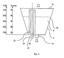
- a vessel 5 ( figure 6 ) having a bottom wall 6b and a side wall 6a comprises an inlet 7a and an outlet 7b, wherein the outlet is located in the bottom wall 6b.
- the vessel 5 is open at the upper side which forms the inlet 7a.
- the shape of the vessel is defined by side wall 6a which are inclined upwards like a cone. At the left hand sight of vessel 5 there is indicated the height h in mm and the corresponding filling volume V 0 . There is a non-linear correlation between height h and volume V because the volume increases in a non-linear manner when the water level rises.
- both measuring electrodes 22, 24 are used to measure the hardness value.
- the rising water level contacts the lower tips of both electrodes so that a first measurement can be done. Since the measuring device is in the status "waiting for water" the first measurement is the measurement of the first reference measured value x 1 . After this measurement all further measurements concern the measurement of the measured values x.
- the second embodiment two measuring electrodes and a reference electrode
- only one measuring electrode 22 or 24 and the reference electrode 26 are used to measure the hardness value.
- One first measurement concerns the measurement of x between electrodes 22, 24 and another first measurement concerns the measurement of x 1 between f. e. electrode 22 and the reference electrode 26.
- the hardness value H is determined by comparison x 1 with the values of table 1.
- both values x and x 1 are measured, whereby a change of the hardness value can be detected by a change of the values x 1 .
- the measured value x might be falsified by various parameters. Therefore it is recommended to normalize the measured value x by the reference measurement of the reference electrode 26.
- the electronic components of the evaluation unit 12 might also falsify the measured values. Therefore, it is recommended the first reference measured value x 1 by a measurement of the reference resistor R 0 located in the reference circuit 15 in order to determine the second reference measured value x 2 .
- FIG. 8 An improved first reference table 1 a is shown in figure 8 .
- table 2 contains the measured values x instead of I 1 .
- a fourth table (table 4, figure 11 ) is used.
- the volume values It is preferred to determine the volume values and to compare them with the V max value every time when the value x is measured.
- the value x is preferably measured five times a second, so that a high precision can be achieved.
Abstract
Description
- The invention refers to a method of measurement of the volume of rate of flow of electrically conductive liquids through a vessel according to
claim 1. The invention also refers to a respective measuring device. - The measurements of filling heights are conducted wherever the volumes of liquids and the alteration of volume have to be determined. The measurements of filling heights are usually done by electrodes, which immerse at least partially into the liquid. The electrical conductivity or the resistance of the liquid, which is proportional to the filling height or the volume of the liquid, is measured by a suitable measuring device.
- Such measurements are necessary in order to determine the exhaustion of filter cartridges, which are used in gravitation driven filtration devices.
-
WO 02/27280 A - A similar device is known from
EP 1 484 097 B1 - In case of consideration a partial filling of the vessel numerous electrodes are located on growing levels in a compensation chamber within the vessel.
- This device is expensive and never even takes into consideration the design and shape of the vessel. Exact measurements of volume require intermediate measurements of the filling height taking into account the vessel shape. Usually, the vessel has any design so that the correlation between filling height and liquid volume doesn't follow a simple mathematical formula.
- Most of the measuring devices ignore vessel shape so that the determination of life-span of the filter cartridge is not as precise as it should be.
-
US 4,724,705 A relates to a fuel measurement device and particularly a device for determining for quantity of a fuel in a fuel tank. The fuel level indicator includes a hollow housing, a coded wafer, a short circuit wafer including a wafer substrate, a buoyant member and a continuity bridge. The coded wafer is made of a dielectric, ceramic material and extends along the interior length of the hollow housing. An electrically conductive wire strand having a known resistance per unit length is wound about the coded wafer to define a "pattern of resistance" representative of the contour of the interior wall of the fuel tank. The manufacturing of the fuel level indicator is quite an effort, in particular for manufacturing of the coded wafer. -
US 5,831,174 discloses a pump station flowmeter including a pump status comparator for creating level status without being connected to any level sensors by comparing pump status to a list of association between expected pump status and levels. The wet well dimension, pump status signals, clock signals, level status are recorded in memory before being used as input to a flow calculator which calculates inflow and outflow. A flow rectifier readjusts the inflow and outflow according to a variable proportion of the difference between the average of many outflows and one outflow, and using this difference to readjust a variable tolerance and the variable position. Abnormal pump operations are confirmed when a predetermined number of possible abnormal pump operations occur in a row are detected by comparing the outflow to the average of many outflows plus or minus the variable tolerance. A maintenance status is declared when an outflow calculated is physically impossible so the inflow calculated is the time of operation of the pumps divided by the time of maintenance status. -
DE 10 2005 035 045 A1 - The objective of the invention is to provide a method and a measuring device which allows to measure the volume of rate of flow through a vessel in a more precise and easy manner.
- This objective is solved by a method, which is characterized in that the measured values x are measured in time intervals and that the respective filling volumes V0 are determined by comparison of the respective measured values x with calibration measured values XR of at least one reference table comprising at least calibration measured values XR and filling volumes V0 belonging to them, and that the volume VD of the rate of flow is determined from the filling volumes V0 over a time period, wherein the at least one reference table is constructed by means of calibration measurements using several liquid samples, which have different p-values and different filling heights h in the vessel.
- The time period, in which the filling volumes Vo are measured, can be a predetermined time period. In case that the method of measurement is applied f. e. to a filtration device, the starting time can be the time when f. e. a new filter cartridge is put into the device. In this case the time period is limited f. e. by the life time of the cartridge or the time period until the cartridge is replaced.
- The benefit of the invention is that simple electrodes can be used and that the parameter p and the shape of the vessel, which both influence the results of the measurements of the filling height h and therefore of the filling volume V0, can be taken into consideration by constructing at least one reference table.
- The calibration measured values XR contained in this reference table are constructed for each shape of the vessel and are deposited in the memory of the electrical conductivity measuring device. The mechanical features of the measuring device, in particular the shape and technical details of the electrodes, need not to be adapted to the shape of the vessel when one type of measuring device is used in different vessels. It is only necessary to provide the respective table or tables containing the specific values which reflect the shape and the different types of liquid flowing through the vessel. If the vessels are mass-products only, the construction of at least of one table for each type of vessel is necessary and one and the same measuring device can be used without mechanical adaption.
- The values of the liquid volume in the vessel can be measured in a very precise manner, because not only parameter p but also the shape of the vessel are taken into consideration when the calibration measurements are conducted.
- The at least one reference table can be deposited in a memory of the measuring device.
- One reference table can be sufficient, if for example the influence of parameter p on the measurement of the filling height h is less or not significant and/or there is for example a linear relationship between V0 and the shape of the vessel. In these cases the correlation between x and h and therefore between x and V0 can be unique.
- However, in cases, where the influence of parameter p or where more than one parameter p is getting significant on the result, more than one reference table is needed. The same is true when there is a non-linear correlation between x and V0. All these facts result in ambiguous values, if only one table is used. This problem can be overcome by construction of more than one table, for example two or three reference tables in order to get unique and precise results.
- It is preferred that a first reference measured value X1 is measured at least once during said time period.
- This first reference measured value X1 is used to determine at least one of the parameters p of the liquid, which f. e. can be the hardness of water. It is further preferred that the first reference measured value X1 is measured only once at the beginning of a filling procedure starting from an empty vessel. Before the beginning of filling the measuring device is in the status "waiting for water" so that at the first contact of the electrodes with the liquid results in the measurement of the first reference measured value X1. After this measurement the measuring device switches into the status "height measurement" so that all following measured values are classified as measured values x.
- The first reference measured value X1 is stored and can be used for the calibration of the measured values x until the vessel is empty again and the next filling of the vessel has been started. According to this embodiment it is preferred that said first reference measured value X1 is measured by the same two measuring electrodes which are used for the measuring of measured values x.
- According to another embodiment it is preferred that this first reference measured value X1 is measured every time when the measured value x is measured. In this case the measuring device does not distinguish between the very first measurement at the beginning of the filling procedure and the following measurements. This kind of measurement is more precise however it needs a reference electrode. The first reference measured value X1 is measured by this reference electrode and one of the measuring electrodes which are used for the measurements of measured values x.
- As illustrated in connection with the measuring device, this electrode is shielded with the exception of the lower surface.
- It is preferred that a first reference table is constructed which contains the calibration first reference measured values X1R, which are corresponding to the first reference measured value X1, and the respective values of parameter p belonging to them. It is also preferred to construct a second reference table which at least contains the calibration measured values XR, the values of parameter p and the respective filling heights h belonging to them and to construct a third reference table which takes into consideration the shape of the vessel and which contains the filling heights h and the respective filling volumes V0 belonging to them.
- It is preferred to determine the value of parameter p at least from the first reference measured value X1 by comparison with the first reference table.
- It is also preferred to determine the filling height h at least from the measured value x and the values of the parameter p by comparison with the values of the second reference table.
- The respective filling volume V0 can be determined from the filling height h by comparison with the values of the third reference table.
- Starting with the measurement of the measured values x it is a step by step procedure to achieve the filling volume V0.
- It is preferred to use a first calibrated value I1 which is a function of x and X1 instead of x only. Therefore, in the reference tables 1 and 2 XR is replaced by the corresponding first calibrated value I1. Preferably, the first calibrated value I1 is I1 = X1/x.
- It is preferred that a second reference measured value X2 is measured at least once during said time period.
- This second reference measured value X2 can be measured at the beginning of the filling procedure started from an empty vessel or it can be measured every time when the measured value x is measured.
- This second reference measured value X2 is preferably measured by means of a reference circuit of the electrical conductivity measuring device.
- In order to consider temperature drifts of the electronic part of the measuring device it is preferred to refer and therefore to calibrate the value X1 to the second reference measured value X2. Preferably, such a second calibrated value I2 is I2 = X2/X1.
- This step contributes to the improvement of the precision of the volume measurement.
- Therefore it is preferred to introduce I2 into the first reference table, which contains I1, I2 and the parameter p. From both values I1 and I2 the parameter p can be determined in a more precise manner.
- Although I1 = x1 / x and I2 = X2 / x1, both values can be multiplied by a suitable factor to achieve figures which can be handled easier. It is preferred to achieve values without decimal point.
- The values of the parameter p can be determined from the values I1 and I2 by comparison with values of the first reference table.
- The filling height h can be determined from the values of parameter p and the first calibrated value I1 by comparison with values of the second reference table.
- Although the claimed method can be used to measure the volume of the flow rate of various liquids, the measurement of water is preferred. In case of water, the parameter p is the hardness H, which is the most important property of water that affects the electrical conductivity. It's possible to use another property of the liquid as parameter p, f. e. the pollution of the water.
- In a preferred embodiment the measured values x, X1 and/or X2 are a time values.
- The electrical conductivity measuring device comprises an electrical circuit which preferably comprises a capacitor means. The charging and/or the discharging time of this capacitor means can be used as measured values X, because it depends from the filling height of the liquid in the vessel.
- The measured values x are measured at least once per second. It is preferred to measure the measured values x at least five times per second.
- It is preferred to measure not only the measured value x but also X1 and X2 and to calculate I1 and I2. This can be done by an appropriate electronic device which is part of the electrical conductivity measuring device.
- In a preferred embodiment the changes ΔV of the filling volumes V0 are determined and the volume VD of the flow rate is determined from the volume changes ΔV.
- It is preferred to determine the volume VD of the flow rate from the respective volume increase. This embodiment is preferred if the filling of the vessel happens more rapidly than the draining off of the liquid, f. e. faster by a factor of at least 10. It is assumed that the amount of liquid which is filled in is equivalent to the amount that is drained off.
- The volume VD of the flow rate is compared with a volume Vmax, which is the maximum volume of the liquid, that is characterized by the at least one parameter p and which volume is allowed to flow through the filter device which is arranged downstream of the vessel. This filter device contains at least one filter medium. The exhaustion of the filter medium is indicated, when Vmax is reached.
- The maximum volume Vmax depends on the at least one parameter p, for example on the hardness H in case of water. Therefore, a fourth reference table is recommended which contains the respective volume Vmax for various values of parameter p. Vmax can be determined by comparison of the values of the parameter p with the corresponding values deposited in the fourth reference table.
- The exhaustion of the filter medium can be indicated acoustically and/or optically.
- It is another possibility to indicate remaining volumes acoustically and/or optically until the exhaustion of the filter medium is reached.
- It is preferred to use a filter cartridge as a filtering device. This filter cartridge can be arranged in the outlet of the vessel.
- The objective of the invention is also solved with a measuring device for the determination of the volume VD of the flow rate of electrical conductive liquids through a vessel wherein the filling heights h are changing in the vertical direction and wherein the vessel comprises an inlet and an outlet, and a conductivity measuring device which comprises an evaluation unit and at least two measuring electrodes wherein the measuring electrodes are located in the vessel and are connected to the evaluation unit, wherein at least one measured value x is measured by the electrodes characterized in that the evaluation unit is configured for the deposition of at least one reference table comprising at least calibration measured values XR and filling volumes V0 belonging to them and for comparison of the measured values x of the conductivity measuring device with the calibration measured values XR of the at least one reference table and for the determination of the volume VD of the flow rate from the filling volumes V0.
- Both measuring electrodes preferably extend over the total filling height of the vessel wherein these measuring electrodes are not shielded over the total filling height.
- As explained in connection with the claimed method, a reference electrode is provided which is arranged near both measuring electrodes. This reference electrode is preferably shielded with the exception of its lower surface.
- The electrodes can comprise a constant cross-section along the total length. The benefit of these simple electrodes is the fact that the electrodes can be cut from a long wire in order to adapt the electrodes to the height of the vessel. It is not necessary to manufacture specific electrodes for each type of vessel.
- The evaluation unit preferably comprises a capacitor means. As illustrated in connection with the claimed method the charging and/or discharging time of the capacitor means is the measured value x.
- The evaluation unit preferably comprises a reference circuit having a reference resistor R0.
- Furthermore, it is preferred that the measuring device encompasses an indicator unit which can be an optical or an acoustical unit.
- In order to simplify the manufacturing of the measuring device, the electrodes can be combined to a measuring stick. It is preferred that the measuring stick is integrated into the wall of the vessel.
- The vessel can be a feeding hopper of a water filtration device.
- A preferred use of the measuring device is the exhaustion measuring device for filter cartridges.
- The indicator unit can preferably indicate the time of change of the filter cartridge.
- Preferred embodiments are illustrated in connection with the following drawings:
- Fig. 1
- shows a schematic view of a measuring device,
- Fig. 2
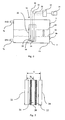
- shows the measuring stick comprising three electrodes,
- Fig. 3
- shows a vertical cross-section of a jug containing a vessel and measuring device,
- Fig. 4
- shows the electrical circuit of the measuring device,
- Fig. 5
- shows a diagram how the measured value x is calculated from the charging and discharging time of the capacitor means,
- Fig. 6
- shows a vertical cross section of a vessel
- Fig. 7
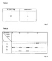
- table 1,
- Fig. 8
- table 1a,
- Fig. 9
- table 2,
- Fig. 10
- table 3 and
- Fig. 11
- table 4.
- In
fig. 1 there is shown asimplified vessel 5 which is filled with water up to thewater level 40. The vessel comprises abottom wall 6b and asidewall 5 having aninlet 7a and anoutlet 7b. Inside the vessel there is located a measuringstick 20 which is approximately 5 mm above thebottom wall 6b ofvessel 5. - The measuring stick comprises two measuring
electrodes 22, 24 (first embodiment) and an additional reference electrode 26 (second embodiment) which is located between the measuringelectrodes electrical connections evaluation unit 12 which is connected to anindication unit 14. If thewater level 40 rises up to water level 40', the volume change is measured by the measuring device. - In
fig. 2 and in the followingfig. 3 and4 it is illustrated the second embodiment wherein the measuringelectrodes reference electrode 26 is shielded by ashield 27 whereas thelower surface 28 is unshielded. - In
fig. 3 awater filtration device 1 is shown which comprises ajug 2 having agrip 3 and a feeding hopper which forms thevessel 5. In the outlet ofvessel 5 there is located afilter cartridge 50. The measuringdevice 10 is located insidevessel 5 and the electrodes are connected to the evaluation unit and to the indication unit which are arranged in thelid 4. Water to be filtered 8 is filled intovessel 5. After the filtration by thefilter cartridge 50 the filtered water 9 flows into and is collected in thejug 2. - In
fig. 4 the threeelectrodes reference circuit 15 in which areference resistor 17 is arranged. Furthermore, there is a capacitor means 16 which is charged and discharged by switching theswitches - In
fig. 5 the diagram that corresponds to the charging and discharging of the capacitor means 16 is shown. In a first step the capacitor means is brought to a well defined voltage value by charging and discharging it. After time T3 is reached, the measuring procedure is started. The capacitor means is charged until 1.5 Volts are reached and then it is discharged until the starting value of 0.75 Volts is reached. The sum of the charging time T4 and the discharging time T5 is used as measured value x. - The method of determination of rate of flow of water is depicted in detail in connection with
figures 6 to 11 . - A vessel 5 (
figure 6 ) having abottom wall 6b and aside wall 6a comprises aninlet 7a and anoutlet 7b, wherein the outlet is located in thebottom wall 6b. Thevessel 5 is open at the upper side which forms theinlet 7a. - The shape of the vessel is defined by
side wall 6a which are inclined upwards like a cone. At the left hand sight ofvessel 5 there is indicated the height h in mm and the corresponding filling volume V0. There is a non-linear correlation between height h and volume V because the volume increases in a non-linear manner when the water level rises. - The correlation between h and V0 is deposited in table 3 (
figure 10 ). - In order to measure the hardness value H there are two options.
- According to the first embodiment (only two electrodes) both measuring
electrodes - When the
vessel 5 is empty and the water is filled in, the rising water level contacts the lower tips of both electrodes so that a first measurement can be done. Since the measuring device is in the status "waiting for water" the first measurement is the measurement of the first reference measured value x1. After this measurement all further measurements concern the measurement of the measured values x. - This single first reference measured value x1 is used to determine the hardness value H by comparison with the values of table 1 (first table). If x1 = 20 µs/cm, the hardness value H is 3. This value x1 is stored in the memory of the measuring device and during the further filling process only values x are measured.
- According to the second embodiment (two measuring electrodes and a reference electrode) only one measuring
electrode reference electrode 26 are used to measure the hardness value. - When the
vessel 5 is empty and the water is filled in, the rising water level contacts the lower tips of both electrodes so that first measurements can be done. - One first measurement concerns the measurement of x between
electrodes electrode 22 and thereference electrode 26. The hardness value H is determined by comparison x1 with the values of table 1. - During the following filling process always both values x and x1 are measured, whereby a change of the hardness value can be detected by a change of the values x1.
- However, the measured value x might be falsified by various parameters. Therefore it is recommended to normalize the measured value x by the reference measurement of the
reference electrode 26. The first calibrated value I1 = x1/x is for example 15. - However, the electronic components of the
evaluation unit 12 might also falsify the measured values. Therefore, it is recommended the first reference measured value x1 by a measurement of the reference resistor R0 located in thereference circuit 15 in order to determine the second reference measured value x2. This second calibration results in the second calibrated value I2, which is I2 = x2/x1. - An improved first reference table 1 a is shown in
figure 8 . - If for example I2 = 2500, this value can be found in different rows of table 1 a. However I1 = 15 is known so that the corresponding hardness value H must be 3.
- In the next step the actual height h has to be found which corresponds to the measured value x.
- In a second reference table (table 2,
figure 9 ) which contains the hardness H and the I1 - values, h = 50 mm can be found. - If the calibration is not conducted and therefore I1 is not determined, table 2 contains the measured values x instead of I1.
- Since the shape and the volume of the vessel doesn't correlate in a linear manner with the filling height, it is necessary to look into a third reference table (table 3,
figure 10 ), where the corresponding volume value V0 can be found. Since the measurement of value x starts from the beginning of the filling procedure, the difference volumes ΔV have to be added. When reaching h = 50 mm the total volume is 1,2 1, which is the sum of the difference values ΔV in table 3 up to the height value h = 50 mm. - In order to determine the life-span of the filter cartridge, a fourth table (table 4,
figure 11 ) is used. The hardness value is 3 which corresponds to Vmax = 1201. - All tables have been prepared for a specific filtration device and have been deposited in the memory in the measuring device.
- It is preferred to determine the volume values and to compare them with the Vmax value every time when the value x is measured. The value x is preferably measured five times a second, so that a high precision can be achieved.
-
- 1
- water filtration device
- 2
- jug
- 3
- grip
- 4
- lid
- 5
- vessel
- 6a
- side wall
- 6b
- bottom wall
- 7a
- inlet
- 7b
- outlet
- 8
- water to be filtered
- 9
- filtered water
- 10
- measuring device
- 12
- evaluation unit
- 14
- indication unit
- 15
- reference circuit
- 16
- capacitor means
- 17
- reference resistor
- 18
- switch
- 19
- switch
- 20
- measuring stick
- 22
- measuring electrode
- 24
- measuring electrode
- 26
- reference electrode
- 27
- shield
- 28
- lower surface
- 30
- electrical connection
- 32
- electrical connection
- 33
- electrical connection
- 40
- water level
- 40'
- water level
- 50
- filter cartridge
- x
- measured value
- XR
- calibration measured value (in the table)
- X1
- first reference measured value
- X1R
- calibration first reference measured value
- X2
- second reference measured value
- X2R
- calibration second reference measured value
- V0
- filling volume
- VD
- volume of the flow-rate of the electrical conductive liquid
- I1
- first calibrated value
- I2
- second calibrated value
- h
- filling height
- Vmax
- maximum volume of the liquid characterized by a parameter p that is allowed to flow through a filter device
Claims (15)
- Method of measurement of the volume VD of the flow-rate of electrically con-ductive liquids the conductivity of which is at least codetermined by at least one parameter p,
wherein the liquid flows through a vessel having a predetermined shape, and wherein the respective filling volume V0 in the vessel is determined by at least one measured value x, which is measured by an electrical conductivity measuring device comprising at least two measuring electrodes,
wherein the vessel is filled in succession and then is emptied through its outlet, through which the filling heights h are constantly changing, characterized in
that the measured values x are measured in time intervals and that the respective filling volumes V0 are determined by comparison of the respective measured values x with calibration measured values xR of at least one reference table comprising at least calibration measured values xR and filling volumes V0 belonging to them, and
that the volume VD of the rate of flow is determined from the filling volumes V0 over a time period,
wherein the at least one reference table is constructed by means of calibration measurements using several liquid samples, which have different p-values and different filling heights h in the vessel. - Method according to claim 1, characterized in that a first reference measured value x1 is measured at least once during said time period.
- Method according to one of claims 1 or 2, characterized in that a first reference table is constructed, which contains calibration first reference measured values x1R and values of parameter p belonging to them,
that a second reference table is constructed which contains at least the calibration measured values xR, the values of parameter p and the filling heights h belonging to them and that a third reference table is constructed which takes into account the shape of the vessel and which contains the filling heights h and the volumes V0 belonging to them. - Method according to claim 3, characterized in that the value of parameter p is determined at least from the first reference measured value x1 by comparison with the values of first reference table,
that the filling height h is determined from at least the measured value x and the values of parameter p by comparison with the values of the second reference table and
that the respective filling volume V0 is determined from the filling height h by comparison with the values of the third reference table. - Method according to one of claims 2 to 4, characterized in that the measured value x is referred to the first reference measured value x1 in order to determine a first calibrated value I1.
- Method according to one of the claims 1 to 5, characterized in that a second reference measured value x2 is measured at least once during said time period.
- Method according to one of claims 1 to 6, characterized in that the first reference measured value x1 is referred to the second reference measured value x2 in order to determine a second calibrated value I2.
- Method according to one of claims 1 to 7, characterized in that the values of the parameter p are determined from the calibrated values I1 and I2 by comparison with the values of the first reference table.
- Method according to one of claims 1 to 8, characterized in that the filling height h is determined from the values of parameter p and the first calibrated value I1 by comparison with the values of the second reference table.
- Method according to one of claims 1 to 9, characterized in that the filling volume V0 of water is determined.
- Method according to one of claims 1 to 10, characterized in that the changes ΔV of the filling volume V0 are determined and that the volume VD of the flow rate is determined from the volume changes ΔV.
- Method according to claim 11, characterized in that the volume VD of the flow rate is determined from the respective volume increase.
- Method according to one of claims 11 or 12, characterized in that the volume VD of the flow rate is compared with a volume Vmax, wherein Vmax designates the maximum volume of the liquid characterized by at least one parameter p and is allowed to flow through a filter device which is arranged downstream to the vessel and which contains at least one filter medium and that the exhaustion of the filter medium is indicated, when Vmax is reached.
- Measuring device (10) for the determination of the volume VD of the flow-rate of electrically conductive liquids through a vessel (5) wherein the filling heights h are changing in the vertical direction and wherein the vessel (5) comprises an inlet (7a), an outlet (7b) and a conductivity measuring device which comprises an evaluation unit (12) and at least two measuring electrodes (22, 24) wherein the measuring electrodes (22, 24) are located in the vessel (5) and are connected to the evaluation unit (12), wherein at least one measured value x is measured by the measuring electrodes characterized in that the evaluation unit (12) is configured for the deposition of at least one reference table comprising at least calibration measured values xR and filling volumes V0 belonging to them and for comparison of the measured values x of the conductivity measuring device with the calibration measured values xR of the at least one reference table and for the determination of the volume VD of the flow rate from the filling volumes V0.
- Use of the measuring device according to one of the claims 14 as exhaustion measuring device for filter cartridges (50).
Priority Applications (2)
| Application Number | Priority Date | Filing Date | Title |
|---|---|---|---|
| PL09725047T PL2265905T3 (en) | 2008-03-28 | 2009-03-27 | Method for measuring the volume flow of electrically conductive liquids through a vessel |
| EP09725047A EP2265905B1 (en) | 2008-03-28 | 2009-03-27 | Method for measuring the volume flow of electrically conductive liquids through a vessel |
Applications Claiming Priority (4)
| Application Number | Priority Date | Filing Date | Title |
|---|---|---|---|
| EP08153500 | 2008-03-28 | ||
| DE102008054479A DE102008054479A1 (en) | 2008-12-10 | 2008-12-10 | Conductivity measuring device and liquid treatment device |
| PCT/EP2009/053644 WO2009118402A1 (en) | 2008-03-28 | 2009-03-27 | Method for measuring the volume flow of electrically conductive liquids through a vessel |
| EP09725047A EP2265905B1 (en) | 2008-03-28 | 2009-03-27 | Method for measuring the volume flow of electrically conductive liquids through a vessel |
Publications (2)
| Publication Number | Publication Date |
|---|---|
| EP2265905A1 EP2265905A1 (en) | 2010-12-29 |
| EP2265905B1 true EP2265905B1 (en) | 2012-07-04 |
Family
ID=40578610
Family Applications (1)
| Application Number | Title | Priority Date | Filing Date |
|---|---|---|---|
| EP09725047A Active EP2265905B1 (en) | 2008-03-28 | 2009-03-27 | Method for measuring the volume flow of electrically conductive liquids through a vessel |
Country Status (12)
| Country | Link |
|---|---|
| US (1) | US8171802B2 (en) |
| EP (1) | EP2265905B1 (en) |
| JP (1) | JP5559141B2 (en) |
| CN (1) | CN101981415B (en) |
| BR (1) | BRPI0910117A2 (en) |
| CA (1) | CA2712055A1 (en) |
| ES (1) | ES2387188T3 (en) |
| MX (1) | MX2010007963A (en) |
| PL (1) | PL2265905T3 (en) |
| RU (1) | RU2488779C2 (en) |
| TW (1) | TW200946881A (en) |
| WO (1) | WO2009118402A1 (en) |
Families Citing this family (12)
| Publication number | Priority date | Publication date | Assignee | Title |
|---|---|---|---|---|
| ITTO20110258A1 (en) * | 2011-03-24 | 2012-09-25 | Eltek Spa | SENSOR AND / OR DUCT FOR DETECTION OF LIQUIDS, IN PARTICULAR FUELS FOR VEHICLES |
| US9108423B2 (en) * | 2011-05-31 | 2015-08-18 | Funai Electric Co., Ltd. | Consumable supply item with fluid sensing for micro-fluid applications |
| JP6158057B2 (en) | 2013-12-04 | 2017-07-05 | 株式会社東芝 | Electrode type liquid level detection device and electrode type liquid level detection method |
| EP2960210A1 (en) | 2014-06-26 | 2015-12-30 | Electrolux Appliances Aktiebolag | Pitcher having a smart indicator of a filter condition thereof |
| JP6419025B2 (en) * | 2015-05-27 | 2018-11-07 | キヤノン株式会社 | Power supply device, printer, and control method |
| CN106500797A (en) * | 2016-12-09 | 2017-03-15 | 深圳市朗科智能电气股份有限公司 | Liquid level detection device and method |
| CN106768101A (en) * | 2016-12-09 | 2017-05-31 | 深圳市朗科智能电气股份有限公司 | Detecting device for liquid flow and method |
| WO2018103198A1 (en) * | 2016-12-09 | 2018-06-14 | 深圳市朗科智能电气股份有限公司 | Apparatus and method for liquid level detection |
| US10969262B1 (en) * | 2020-08-18 | 2021-04-06 | Larq, Inc. | Filtering container with time-based capacitive flow monitoring |
| US11112763B1 (en) | 2020-08-18 | 2021-09-07 | Larq, Inc. | Monitoring and performance management system for a network of smart filtering containers |
| CN117482389A (en) * | 2023-12-29 | 2024-02-02 | 深圳市宗匠科技有限公司 | Output power adjusting method, beauty instrument, storage medium and electronic equipment |
| CN117629347A (en) * | 2024-01-25 | 2024-03-01 | 北京博泰至淳生物科技有限公司 | Electrode liquid level meter and use method thereof |
Family Cites Families (37)
| Publication number | Priority date | Publication date | Assignee | Title |
|---|---|---|---|---|
| DE1133140B (en) | 1958-12-12 | 1962-07-12 | Heidelberg Portland Zement | Device for continuous or step-by-step measurement of the filling height of an electrically conductive substance in a silo |
| FR1436080A (en) | 1965-03-12 | 1966-04-22 | Improvements to conductimetric detectors for liquid level measurement | |
| DE1798256A1 (en) | 1968-09-17 | 1972-01-20 | Schmitz Ludwig Dipl Ing | Method and device for linear flow measurement of liquids in pressure-free flow channels and measuring cross-sections, in particular of water and waste water |
| US3678749A (en) | 1970-02-25 | 1972-07-25 | Patrick D Harper | Floatless fluid level gauge |
| DE2749547C2 (en) | 1977-11-05 | 1979-10-18 | Gustav F. Gerdts Kg, 2800 Bremen | Probe for continuous level measurement |
| US4169377A (en) * | 1978-04-17 | 1979-10-02 | Nalco Chemical Company | Quantity sensing system for a container |
| DE3018718C2 (en) | 1980-05-16 | 1983-09-08 | Elba-Füllstandsgeräte GmbH, 6149 Rimbach | Level electrode device |
| JPS57104354A (en) | 1980-12-20 | 1982-06-29 | Toshiba Corp | Button telephone set |
| US4426878A (en) * | 1981-10-13 | 1984-01-24 | Core Laboratories, Inc. | Viscosimeter |
| EP0152644A3 (en) | 1983-12-01 | 1988-06-29 | Richard Mulder | Gauge for measuring the level or the conductance of a liquid present between two electrodes. |
| BR8503704A (en) | 1984-08-09 | 1986-05-06 | Tlv Co Ltd | DEBITOMETER TO MEASURE THE DEBIT OF A LIQUID |
| CN85202918U (en) * | 1985-07-08 | 1986-07-09 | 湖南大学 | Sensor for measuring the flow of conductive liquid |
| DE8701392U1 (en) | 1986-02-04 | 1987-03-26 | Turbo-Werk Messtechnik Gmbh, 5000 Koeln, De | |
| US4724705A (en) | 1986-03-31 | 1988-02-16 | Stant Inc. | Fuel gauge |
| DE4042257A1 (en) | 1990-12-31 | 1992-07-02 | Rudolf Rammner | Electrically conducting liquids level measurement - using discrete sensor positions, e.g. inform of metal surfaces along vertical bar |
| JPH0850047A (en) | 1994-08-04 | 1996-02-20 | Hitachi Building Syst Eng & Service Co Ltd | Water-level measuring method |
| CN2235608Y (en) * | 1994-09-16 | 1996-09-18 | 山西耀华高技术公司 | Micro flow rate sensing device |
| US5497664A (en) * | 1994-11-14 | 1996-03-12 | Jorritsma; Johannes N. | Method and apparatus for calculating flow rates through a pumping station |
| DE29522232U1 (en) | 1995-03-29 | 2001-01-18 | Daimler Chrysler Ag | Sensor arrangement |
| DE19511556C1 (en) * | 1995-03-29 | 1996-07-25 | Daimler Benz Ag | Electrical sensor for determn. of state of liq. in container |
| DE19616281C2 (en) * | 1995-04-26 | 2001-04-19 | Murray F Feller | Magnetic flow sensor |
| US5597960A (en) * | 1995-06-05 | 1997-01-28 | Beaudoim; Benott | Pump station flowmeter |
| DE19726044C2 (en) | 1997-06-19 | 1999-06-10 | Effem Gmbh | Liquid level indicator |
| US6431670B1 (en) | 2000-02-14 | 2002-08-13 | Hewlett-Packard Company | Ink level sensing method and apparatus |
| DE10015764A1 (en) | 2000-03-30 | 2001-10-11 | Brita Gmbh | Device for measuring the volume of an electrically conductive liquid |
| DE10047594A1 (en) | 2000-09-26 | 2002-04-18 | Siemens Ag | Method and device for determining the level of a liquid in a container |
| US6711947B2 (en) * | 2001-06-13 | 2004-03-30 | Rem Scientific Enterprises, Inc. | Conductive fluid logging sensor and method |
| WO2003031018A1 (en) * | 2001-10-05 | 2003-04-17 | Unilever Plc | Filter condition indicator |
| JP3891821B2 (en) | 2001-10-29 | 2007-03-14 | 三菱重工食品包装機械株式会社 | Liquid level measuring device and method |
| JP2004077439A (en) | 2002-08-22 | 2004-03-11 | Tsurumi Mfg Co Ltd | Electrode for detecting water level |
| ITPD20030121A1 (en) | 2003-06-04 | 2004-12-05 | Laica Srl Ora Laica S P A | METHOD FOR DETERMINING THE EXHAUSTION CONDITIONS OF |
| US7487677B2 (en) * | 2004-04-19 | 2009-02-10 | Fook Tin Technologies Ltd. | Apparatus and methods for monitoring water consumption and filter usage |
| US7107838B2 (en) * | 2004-04-19 | 2006-09-19 | Fook Tin Technologies Ltd. | Apparatus and methods for monitoring water consumption and filter usage |
| US7516660B2 (en) * | 2004-05-21 | 2009-04-14 | Met Tech, Inc. | Convective accelerometer |
| DE102005035045B9 (en) * | 2005-07-27 | 2007-11-08 | Brita Gmbh | Measuring device for the determination of flow rates of electrically conductive liquids, measuring element and method |
| CA2781625C (en) * | 2006-11-10 | 2015-09-29 | Rem Scientific Enterprises, Inc. | Rotating fluid measurement device and method |
| DE102008054479A1 (en) | 2008-12-10 | 2010-06-17 | Brita Gmbh | Conductivity measuring device and liquid treatment device |
-
2009
- 2009-03-27 TW TW098110081A patent/TW200946881A/en unknown
- 2009-03-27 PL PL09725047T patent/PL2265905T3/en unknown
- 2009-03-27 JP JP2011501239A patent/JP5559141B2/en not_active Expired - Fee Related
- 2009-03-27 US US12/736,263 patent/US8171802B2/en active Active
- 2009-03-27 EP EP09725047A patent/EP2265905B1/en active Active
- 2009-03-27 ES ES09725047T patent/ES2387188T3/en active Active
- 2009-03-27 RU RU2010144054/28A patent/RU2488779C2/en active
- 2009-03-27 CA CA2712055A patent/CA2712055A1/en not_active Abandoned
- 2009-03-27 CN CN2009801110504A patent/CN101981415B/en not_active Expired - Fee Related
- 2009-03-27 MX MX2010007963A patent/MX2010007963A/en not_active Application Discontinuation
- 2009-03-27 WO PCT/EP2009/053644 patent/WO2009118402A1/en active Application Filing
- 2009-03-27 BR BRPI0910117A patent/BRPI0910117A2/en not_active Application Discontinuation
Also Published As
| Publication number | Publication date |
|---|---|
| RU2010144054A (en) | 2012-05-10 |
| PL2265905T3 (en) | 2012-10-31 |
| TW200946881A (en) | 2009-11-16 |
| CN101981415B (en) | 2013-03-13 |
| JP2011519020A (en) | 2011-06-30 |
| US8171802B2 (en) | 2012-05-08 |
| RU2488779C2 (en) | 2013-07-27 |
| MX2010007963A (en) | 2010-08-11 |
| BRPI0910117A2 (en) | 2015-12-29 |
| WO2009118402A1 (en) | 2009-10-01 |
| EP2265905A1 (en) | 2010-12-29 |
| CN101981415A (en) | 2011-02-23 |
| CA2712055A1 (en) | 2009-10-01 |
| US20110011184A1 (en) | 2011-01-20 |
| ES2387188T3 (en) | 2012-09-17 |
| JP5559141B2 (en) | 2014-07-23 |
Similar Documents
| Publication | Publication Date | Title |
|---|---|---|
| EP2265905B1 (en) | Method for measuring the volume flow of electrically conductive liquids through a vessel | |
| US7487677B2 (en) | Apparatus and methods for monitoring water consumption and filter usage | |
| EP1931954B1 (en) | METHOD AND APPARATUS FOR DETECTING LIQUID LEVELS IN LIQUID-STORAGE CONTAINERS from a hematology instrument | |
| JP4976390B2 (en) | Measuring device, conductivity measuring device, measuring element and method for determining flow capacity of conductive liquid | |
| CN101297180B (en) | Capacitive gauge for fuel tank | |
| JP2011519020A5 (en) | ||
| US7294277B2 (en) | Method of determination of the conditions of exhaustion of a filtering cartridge for filtering carafes with replaceable cartridge and carafe operating in compliance with such method | |
| US20120065904A1 (en) | Aircraft fuel level measurment apparatus and method | |
| CN1690670A (en) | Apparatus and methods for monitoring water consumption and filter usage | |
| EP1884752B1 (en) | Methods and systems for liquid volumetric measurement | |
| NL8203224A (en) | DEVICE FOR DELIVERING VERY SMALL LIQUID QUANTITIES. | |
| EP2960210A1 (en) | Pitcher having a smart indicator of a filter condition thereof | |
| EP1484097B1 (en) | Method of determination of the conditions of exhaustion of a filtering cartridge for filtering carafes with replaceable cartridge and carafe operating in compliance with such method | |
| KR20080063358A (en) | Capacitive gauge | |
| JP2570677B2 (en) | Liquid level meter | |
| RU2460972C1 (en) | Method of determining amount of electroconductive liquid and equipment system for realising said method | |
| CN101287969A (en) | Capacitive gauge | |
| US8689625B2 (en) | Method and apparatus for detecting the level of a liquid in monitoring a dispense/aspirate process | |
| US20220316935A1 (en) | Differentiating between fuel and water using capacitive measurement thereof | |
| WO2022216601A1 (en) | Differentiating between fuel and water using capacitive measurement thereof | |
| SU210469A1 (en) | DEVICE FOR DETERMINING THE VISCOSITY OF ELECTROCONDUCTING LIQUIDS |
Legal Events
| Date | Code | Title | Description |
|---|---|---|---|
| PUAI | Public reference made under article 153(3) epc to a published international application that has entered the european phase |
Free format text: ORIGINAL CODE: 0009012 |
|
| 17P | Request for examination filed |
Effective date: 20101028 |
|
| AK | Designated contracting states |
Kind code of ref document: A1 Designated state(s): AT BE BG CH CY CZ DE DK EE ES FI FR GB GR HR HU IE IS IT LI LT LU LV MC MK MT NL NO PL PT RO SE SI SK TR |
|
| AX | Request for extension of the european patent |
Extension state: AL BA RS |
|
| DAX | Request for extension of the european patent (deleted) | ||
| GRAP | Despatch of communication of intention to grant a patent |
Free format text: ORIGINAL CODE: EPIDOSNIGR1 |
|
| GRAS | Grant fee paid |
Free format text: ORIGINAL CODE: EPIDOSNIGR3 |
|
| GRAA | (expected) grant |
Free format text: ORIGINAL CODE: 0009210 |
|
| AK | Designated contracting states |
Kind code of ref document: B1 Designated state(s): AT BE BG CH CY CZ DE DK EE ES FI FR GB GR HR HU IE IS IT LI LT LU LV MC MK MT NL NO PL PT RO SE SI SK TR |
|
| REG | Reference to a national code |
Ref country code: GB Ref legal event code: FG4D |
|
| REG | Reference to a national code |
Ref country code: CH Ref legal event code: EP |
|
| REG | Reference to a national code |
Ref country code: AT Ref legal event code: REF Ref document number: 565336 Country of ref document: AT Kind code of ref document: T Effective date: 20120715 |
|
| REG | Reference to a national code |
Ref country code: IE Ref legal event code: FG4D |
|
| REG | Reference to a national code |
Ref country code: DE Ref legal event code: R096 Ref document number: 602009008065 Country of ref document: DE Effective date: 20120830 |
|
| REG | Reference to a national code |
Ref country code: ES Ref legal event code: FG2A Ref document number: 2387188 Country of ref document: ES Kind code of ref document: T3 Effective date: 20120917 |
|
| REG | Reference to a national code |
Ref country code: PL Ref legal event code: T3 |
|
| REG | Reference to a national code |
Ref country code: AT Ref legal event code: MK05 Ref document number: 565336 Country of ref document: AT Kind code of ref document: T Effective date: 20120704 |
|
| REG | Reference to a national code |
Ref country code: NL Ref legal event code: VDEP Effective date: 20120704 |
|
| PG25 | Lapsed in a contracting state [announced via postgrant information from national office to epo] |
Ref country code: SI Free format text: LAPSE BECAUSE OF FAILURE TO SUBMIT A TRANSLATION OF THE DESCRIPTION OR TO PAY THE FEE WITHIN THE PRESCRIBED TIME-LIMIT Effective date: 20120704 |
|
| REG | Reference to a national code |
Ref country code: LT Ref legal event code: MG4D Effective date: 20120704 |
|
| PG25 | Lapsed in a contracting state [announced via postgrant information from national office to epo] |
Ref country code: HR Free format text: LAPSE BECAUSE OF FAILURE TO SUBMIT A TRANSLATION OF THE DESCRIPTION OR TO PAY THE FEE WITHIN THE PRESCRIBED TIME-LIMIT Effective date: 20120704 Ref country code: AT Free format text: LAPSE BECAUSE OF FAILURE TO SUBMIT A TRANSLATION OF THE DESCRIPTION OR TO PAY THE FEE WITHIN THE PRESCRIBED TIME-LIMIT Effective date: 20120704 Ref country code: CY Free format text: LAPSE BECAUSE OF FAILURE TO SUBMIT A TRANSLATION OF THE DESCRIPTION OR TO PAY THE FEE WITHIN THE PRESCRIBED TIME-LIMIT Effective date: 20120704 Ref country code: FI Free format text: LAPSE BECAUSE OF FAILURE TO SUBMIT A TRANSLATION OF THE DESCRIPTION OR TO PAY THE FEE WITHIN THE PRESCRIBED TIME-LIMIT Effective date: 20120704 Ref country code: IS Free format text: LAPSE BECAUSE OF FAILURE TO SUBMIT A TRANSLATION OF THE DESCRIPTION OR TO PAY THE FEE WITHIN THE PRESCRIBED TIME-LIMIT Effective date: 20121104 Ref country code: NO Free format text: LAPSE BECAUSE OF FAILURE TO SUBMIT A TRANSLATION OF THE DESCRIPTION OR TO PAY THE FEE WITHIN THE PRESCRIBED TIME-LIMIT Effective date: 20121004 Ref country code: LT Free format text: LAPSE BECAUSE OF FAILURE TO SUBMIT A TRANSLATION OF THE DESCRIPTION OR TO PAY THE FEE WITHIN THE PRESCRIBED TIME-LIMIT Effective date: 20120704 Ref country code: BE Free format text: LAPSE BECAUSE OF FAILURE TO SUBMIT A TRANSLATION OF THE DESCRIPTION OR TO PAY THE FEE WITHIN THE PRESCRIBED TIME-LIMIT Effective date: 20120704 |
|
| PG25 | Lapsed in a contracting state [announced via postgrant information from national office to epo] |
Ref country code: SE Free format text: LAPSE BECAUSE OF FAILURE TO SUBMIT A TRANSLATION OF THE DESCRIPTION OR TO PAY THE FEE WITHIN THE PRESCRIBED TIME-LIMIT Effective date: 20120704 Ref country code: PT Free format text: LAPSE BECAUSE OF FAILURE TO SUBMIT A TRANSLATION OF THE DESCRIPTION OR TO PAY THE FEE WITHIN THE PRESCRIBED TIME-LIMIT Effective date: 20121105 Ref country code: GR Free format text: LAPSE BECAUSE OF FAILURE TO SUBMIT A TRANSLATION OF THE DESCRIPTION OR TO PAY THE FEE WITHIN THE PRESCRIBED TIME-LIMIT Effective date: 20121005 Ref country code: LV Free format text: LAPSE BECAUSE OF FAILURE TO SUBMIT A TRANSLATION OF THE DESCRIPTION OR TO PAY THE FEE WITHIN THE PRESCRIBED TIME-LIMIT Effective date: 20120704 |
|
| PG25 | Lapsed in a contracting state [announced via postgrant information from national office to epo] |
Ref country code: NL Free format text: LAPSE BECAUSE OF FAILURE TO SUBMIT A TRANSLATION OF THE DESCRIPTION OR TO PAY THE FEE WITHIN THE PRESCRIBED TIME-LIMIT Effective date: 20120704 |
|
| PG25 | Lapsed in a contracting state [announced via postgrant information from national office to epo] |
Ref country code: DK Free format text: LAPSE BECAUSE OF FAILURE TO SUBMIT A TRANSLATION OF THE DESCRIPTION OR TO PAY THE FEE WITHIN THE PRESCRIBED TIME-LIMIT Effective date: 20120704 Ref country code: RO Free format text: LAPSE BECAUSE OF FAILURE TO SUBMIT A TRANSLATION OF THE DESCRIPTION OR TO PAY THE FEE WITHIN THE PRESCRIBED TIME-LIMIT Effective date: 20120704 Ref country code: CZ Free format text: LAPSE BECAUSE OF FAILURE TO SUBMIT A TRANSLATION OF THE DESCRIPTION OR TO PAY THE FEE WITHIN THE PRESCRIBED TIME-LIMIT Effective date: 20120704 Ref country code: EE Free format text: LAPSE BECAUSE OF FAILURE TO SUBMIT A TRANSLATION OF THE DESCRIPTION OR TO PAY THE FEE WITHIN THE PRESCRIBED TIME-LIMIT Effective date: 20120704 |
|
| PLBE | No opposition filed within time limit |
Free format text: ORIGINAL CODE: 0009261 |
|
| STAA | Information on the status of an ep patent application or granted ep patent |
Free format text: STATUS: NO OPPOSITION FILED WITHIN TIME LIMIT |
|
| PG25 | Lapsed in a contracting state [announced via postgrant information from national office to epo] |
Ref country code: SK Free format text: LAPSE BECAUSE OF FAILURE TO SUBMIT A TRANSLATION OF THE DESCRIPTION OR TO PAY THE FEE WITHIN THE PRESCRIBED TIME-LIMIT Effective date: 20120704 |
|
| 26N | No opposition filed |
Effective date: 20130405 |
|
| PG25 | Lapsed in a contracting state [announced via postgrant information from national office to epo] |
Ref country code: BG Free format text: LAPSE BECAUSE OF FAILURE TO SUBMIT A TRANSLATION OF THE DESCRIPTION OR TO PAY THE FEE WITHIN THE PRESCRIBED TIME-LIMIT Effective date: 20121004 |
|
| REG | Reference to a national code |
Ref country code: DE Ref legal event code: R097 Ref document number: 602009008065 Country of ref document: DE Effective date: 20130405 |
|
| PG25 | Lapsed in a contracting state [announced via postgrant information from national office to epo] |
Ref country code: MC Free format text: LAPSE BECAUSE OF NON-PAYMENT OF DUE FEES Effective date: 20130331 |
|
| REG | Reference to a national code |
Ref country code: IE Ref legal event code: MM4A |
|
| PG25 | Lapsed in a contracting state [announced via postgrant information from national office to epo] |
Ref country code: IE Free format text: LAPSE BECAUSE OF NON-PAYMENT OF DUE FEES Effective date: 20130327 |
|
| PG25 | Lapsed in a contracting state [announced via postgrant information from national office to epo] |
Ref country code: MT Free format text: LAPSE BECAUSE OF FAILURE TO SUBMIT A TRANSLATION OF THE DESCRIPTION OR TO PAY THE FEE WITHIN THE PRESCRIBED TIME-LIMIT Effective date: 20120704 |
|
| PG25 | Lapsed in a contracting state [announced via postgrant information from national office to epo] |
Ref country code: TR Free format text: LAPSE BECAUSE OF FAILURE TO SUBMIT A TRANSLATION OF THE DESCRIPTION OR TO PAY THE FEE WITHIN THE PRESCRIBED TIME-LIMIT Effective date: 20120704 |
|
| PG25 | Lapsed in a contracting state [announced via postgrant information from national office to epo] |
Ref country code: HU Free format text: LAPSE BECAUSE OF FAILURE TO SUBMIT A TRANSLATION OF THE DESCRIPTION OR TO PAY THE FEE WITHIN THE PRESCRIBED TIME-LIMIT; INVALID AB INITIO Effective date: 20090327 Ref country code: MK Free format text: LAPSE BECAUSE OF FAILURE TO SUBMIT A TRANSLATION OF THE DESCRIPTION OR TO PAY THE FEE WITHIN THE PRESCRIBED TIME-LIMIT Effective date: 20120704 Ref country code: LU Free format text: LAPSE BECAUSE OF NON-PAYMENT OF DUE FEES Effective date: 20130327 |
|
| REG | Reference to a national code |
Ref country code: FR Ref legal event code: PLFP Year of fee payment: 8 |
|
| REG | Reference to a national code |
Ref country code: FR Ref legal event code: PLFP Year of fee payment: 9 |
|
| REG | Reference to a national code |
Ref country code: DE Ref legal event code: R082 Ref document number: 602009008065 Country of ref document: DE |
|
| REG | Reference to a national code |
Ref country code: FR Ref legal event code: PLFP Year of fee payment: 10 |
|
| PGFP | Annual fee paid to national office [announced via postgrant information from national office to epo] |
Ref country code: GB Payment date: 20220203 Year of fee payment: 14 Ref country code: DE Payment date: 20220203 Year of fee payment: 14 Ref country code: CH Payment date: 20220215 Year of fee payment: 14 |
|
| PGFP | Annual fee paid to national office [announced via postgrant information from national office to epo] |
Ref country code: PL Payment date: 20220215 Year of fee payment: 14 Ref country code: IT Payment date: 20220210 Year of fee payment: 14 Ref country code: FR Payment date: 20220209 Year of fee payment: 14 |
|
| PGFP | Annual fee paid to national office [announced via postgrant information from national office to epo] |
Ref country code: ES Payment date: 20220404 Year of fee payment: 14 |
|
| REG | Reference to a national code |
Ref country code: DE Ref legal event code: R081 Ref document number: 602009008065 Country of ref document: DE Owner name: BRITA SE, DE Free format text: FORMER OWNER: BRITA GMBH, 65232 TAUNUSSTEIN, DE |
|
| P01 | Opt-out of the competence of the unified patent court (upc) registered |
Effective date: 20230527 |
|
| REG | Reference to a national code |
Ref country code: DE Ref legal event code: R119 Ref document number: 602009008065 Country of ref document: DE |
|
| REG | Reference to a national code |
Ref country code: CH Ref legal event code: PL |
|
| GBPC | Gb: european patent ceased through non-payment of renewal fee |
Effective date: 20230327 |
|
| PG25 | Lapsed in a contracting state [announced via postgrant information from national office to epo] |
Ref country code: GB Free format text: LAPSE BECAUSE OF NON-PAYMENT OF DUE FEES Effective date: 20230327 |
|
| PG25 | Lapsed in a contracting state [announced via postgrant information from national office to epo] |
Ref country code: LI Free format text: LAPSE BECAUSE OF NON-PAYMENT OF DUE FEES Effective date: 20230331 Ref country code: GB Free format text: LAPSE BECAUSE OF NON-PAYMENT OF DUE FEES Effective date: 20230327 Ref country code: FR Free format text: LAPSE BECAUSE OF NON-PAYMENT OF DUE FEES Effective date: 20230331 Ref country code: DE Free format text: LAPSE BECAUSE OF NON-PAYMENT OF DUE FEES Effective date: 20231003 Ref country code: CH Free format text: LAPSE BECAUSE OF NON-PAYMENT OF DUE FEES Effective date: 20230331 |