EP2267633A1 - Rotation-activated electronic component - Google Patents
Rotation-activated electronic component Download PDFInfo
- Publication number
- EP2267633A1 EP2267633A1 EP09305533A EP09305533A EP2267633A1 EP 2267633 A1 EP2267633 A1 EP 2267633A1 EP 09305533 A EP09305533 A EP 09305533A EP 09305533 A EP09305533 A EP 09305533A EP 2267633 A1 EP2267633 A1 EP 2267633A1
- Authority
- EP
- European Patent Office
- Prior art keywords
- component
- electronic device
- tag
- switch
- antenna
- Prior art date
- Legal status (The legal status is an assumption and is not a legal conclusion. Google has not performed a legal analysis and makes no representation as to the accuracy of the status listed.)
- Withdrawn
Links
- 238000000034 method Methods 0.000 claims description 6
- 230000008569 process Effects 0.000 claims description 6
- 230000001131 transforming effect Effects 0.000 claims description 3
- 239000007788 liquid Substances 0.000 description 7
- 230000006870 function Effects 0.000 description 4
- 230000004044 response Effects 0.000 description 4
- 230000001133 acceleration Effects 0.000 description 2
- 230000000670 limiting effect Effects 0.000 description 2
- 230000003287 optical effect Effects 0.000 description 2
- 101100406385 Caenorhabditis elegans ola-1 gene Proteins 0.000 description 1
- 230000004913 activation Effects 0.000 description 1
- 230000005540 biological transmission Effects 0.000 description 1
- 230000008859 change Effects 0.000 description 1
- 230000003247 decreasing effect Effects 0.000 description 1
- 230000005611 electricity Effects 0.000 description 1
- 239000012530 fluid Substances 0.000 description 1
- 230000014509 gene expression Effects 0.000 description 1
- 238000004519 manufacturing process Methods 0.000 description 1
- 230000005499 meniscus Effects 0.000 description 1
- QSHDDOUJBYECFT-UHFFFAOYSA-N mercury Chemical compound [Hg] QSHDDOUJBYECFT-UHFFFAOYSA-N 0.000 description 1
- 229910052753 mercury Inorganic materials 0.000 description 1
- 230000002265 prevention Effects 0.000 description 1
- 238000009877 rendering Methods 0.000 description 1
- 238000013068 supply chain management Methods 0.000 description 1
Images

Classifications
-
- G—PHYSICS
- G11—INFORMATION STORAGE
- G11B—INFORMATION STORAGE BASED ON RELATIVE MOVEMENT BETWEEN RECORD CARRIER AND TRANSDUCER
- G11B23/00—Record carriers not specific to the method of recording or reproducing; Accessories, e.g. containers, specially adapted for co-operation with the recording or reproducing apparatus ; Intermediate mediums; Apparatus or processes specially adapted for their manufacture
- G11B23/0014—Record carriers not specific to the method of recording or reproducing; Accessories, e.g. containers, specially adapted for co-operation with the recording or reproducing apparatus ; Intermediate mediums; Apparatus or processes specially adapted for their manufacture record carriers not specifically of filamentary or web form
- G11B23/0021—Record carriers not specific to the method of recording or reproducing; Accessories, e.g. containers, specially adapted for co-operation with the recording or reproducing apparatus ; Intermediate mediums; Apparatus or processes specially adapted for their manufacture record carriers not specifically of filamentary or web form discs
- G11B23/0028—Details
- G11B23/0035—Details means incorporated in the disc, e.g. hub, to enable its guiding, loading or driving
- G11B23/0042—Details means incorporated in the disc, e.g. hub, to enable its guiding, loading or driving with provision for auxiliary features
-
- G—PHYSICS
- G01—MEASURING; TESTING
- G01P—MEASURING LINEAR OR ANGULAR SPEED, ACCELERATION, DECELERATION, OR SHOCK; INDICATING PRESENCE, ABSENCE, OR DIRECTION, OF MOVEMENT
- G01P3/00—Measuring linear or angular speed; Measuring differences of linear or angular speeds
- G01P3/02—Devices characterised by the use of mechanical means
- G01P3/16—Devices characterised by the use of mechanical means by using centrifugal forces of solid masses
-
- G—PHYSICS
- G06—COMPUTING; CALCULATING OR COUNTING
- G06K—GRAPHICAL DATA READING; PRESENTATION OF DATA; RECORD CARRIERS; HANDLING RECORD CARRIERS
- G06K19/00—Record carriers for use with machines and with at least a part designed to carry digital markings
- G06K19/06—Record carriers for use with machines and with at least a part designed to carry digital markings characterised by the kind of the digital marking, e.g. shape, nature, code
- G06K19/067—Record carriers with conductive marks, printed circuits or semiconductor circuit elements, e.g. credit or identity cards also with resonating or responding marks without active components
- G06K19/07—Record carriers with conductive marks, printed circuits or semiconductor circuit elements, e.g. credit or identity cards also with resonating or responding marks without active components with integrated circuit chips
- G06K19/0716—Record carriers with conductive marks, printed circuits or semiconductor circuit elements, e.g. credit or identity cards also with resonating or responding marks without active components with integrated circuit chips at least one of the integrated circuit chips comprising a sensor or an interface to a sensor
-
- G—PHYSICS
- G06—COMPUTING; CALCULATING OR COUNTING
- G06K—GRAPHICAL DATA READING; PRESENTATION OF DATA; RECORD CARRIERS; HANDLING RECORD CARRIERS
- G06K19/00—Record carriers for use with machines and with at least a part designed to carry digital markings
- G06K19/06—Record carriers for use with machines and with at least a part designed to carry digital markings characterised by the kind of the digital marking, e.g. shape, nature, code
- G06K19/067—Record carriers with conductive marks, printed circuits or semiconductor circuit elements, e.g. credit or identity cards also with resonating or responding marks without active components
- G06K19/07—Record carriers with conductive marks, printed circuits or semiconductor circuit elements, e.g. credit or identity cards also with resonating or responding marks without active components with integrated circuit chips
- G06K19/073—Special arrangements for circuits, e.g. for protecting identification code in memory
- G06K19/07309—Means for preventing undesired reading or writing from or onto record carriers
- G06K19/07345—Means for preventing undesired reading or writing from or onto record carriers by activating or deactivating at least a part of the circuit on the record carrier, e.g. ON/OFF switches
-
- G—PHYSICS
- G06—COMPUTING; CALCULATING OR COUNTING
- G06K—GRAPHICAL DATA READING; PRESENTATION OF DATA; RECORD CARRIERS; HANDLING RECORD CARRIERS
- G06K19/00—Record carriers for use with machines and with at least a part designed to carry digital markings
- G06K19/06—Record carriers for use with machines and with at least a part designed to carry digital markings characterised by the kind of the digital marking, e.g. shape, nature, code
- G06K19/067—Record carriers with conductive marks, printed circuits or semiconductor circuit elements, e.g. credit or identity cards also with resonating or responding marks without active components
- G06K19/07—Record carriers with conductive marks, printed circuits or semiconductor circuit elements, e.g. credit or identity cards also with resonating or responding marks without active components with integrated circuit chips
- G06K19/077—Constructional details, e.g. mounting of circuits in the carrier
- G06K19/07749—Constructional details, e.g. mounting of circuits in the carrier the record carrier being capable of non-contact communication, e.g. constructional details of the antenna of a non-contact smart card
-
- G—PHYSICS
- G11—INFORMATION STORAGE
- G11B—INFORMATION STORAGE BASED ON RELATIVE MOVEMENT BETWEEN RECORD CARRIER AND TRANSDUCER
- G11B20/00—Signal processing not specific to the method of recording or reproducing; Circuits therefor
- G11B20/00086—Circuits for prevention of unauthorised reproduction or copying, e.g. piracy
- G11B20/0021—Circuits for prevention of unauthorised reproduction or copying, e.g. piracy involving encryption or decryption of contents recorded on or reproduced from a record carrier
- G11B20/00217—Circuits for prevention of unauthorised reproduction or copying, e.g. piracy involving encryption or decryption of contents recorded on or reproduced from a record carrier the cryptographic key used for encryption and/or decryption of contents recorded on or reproduced from the record carrier being read from a specific source
- G11B20/00253—Circuits for prevention of unauthorised reproduction or copying, e.g. piracy involving encryption or decryption of contents recorded on or reproduced from a record carrier the cryptographic key used for encryption and/or decryption of contents recorded on or reproduced from the record carrier being read from a specific source wherein the key is stored on the record carrier
- G11B20/00275—Circuits for prevention of unauthorised reproduction or copying, e.g. piracy involving encryption or decryption of contents recorded on or reproduced from a record carrier the cryptographic key used for encryption and/or decryption of contents recorded on or reproduced from the record carrier being read from a specific source wherein the key is stored on the record carrier the key being stored on a chip attached to the record carrier
-
- G—PHYSICS
- G11—INFORMATION STORAGE
- G11B—INFORMATION STORAGE BASED ON RELATIVE MOVEMENT BETWEEN RECORD CARRIER AND TRANSDUCER
- G11B20/00—Signal processing not specific to the method of recording or reproducing; Circuits therefor
- G11B20/00086—Circuits for prevention of unauthorised reproduction or copying, e.g. piracy
- G11B20/00876—Circuits for prevention of unauthorised reproduction or copying, e.g. piracy wherein physical copy protection means are attached to the medium, e.g. holograms, sensors, or additional semiconductor circuitry
-
- G—PHYSICS
- G11—INFORMATION STORAGE
- G11B—INFORMATION STORAGE BASED ON RELATIVE MOVEMENT BETWEEN RECORD CARRIER AND TRANSDUCER
- G11B23/00—Record carriers not specific to the method of recording or reproducing; Accessories, e.g. containers, specially adapted for co-operation with the recording or reproducing apparatus ; Intermediate mediums; Apparatus or processes specially adapted for their manufacture
- G11B23/28—Indicating or preventing prior or unauthorised use, e.g. cassettes with sealing or locking means, write-protect devices for discs
- G11B23/283—Security features, e.g. digital codes
- G11B23/284—Security features, e.g. digital codes on the record carrier
-
- H—ELECTRICITY
- H01—ELECTRIC ELEMENTS
- H01H—ELECTRIC SWITCHES; RELAYS; SELECTORS; EMERGENCY PROTECTIVE DEVICES
- H01H29/00—Switches having at least one liquid contact
- H01H29/26—Switches having at least one liquid contact with level of surface of contact liquid displaced by centrifugal action
-
- H—ELECTRICITY
- H01—ELECTRIC ELEMENTS
- H01H—ELECTRIC SWITCHES; RELAYS; SELECTORS; EMERGENCY PROTECTIVE DEVICES
- H01H35/00—Switches operated by change of a physical condition
- H01H35/06—Switches operated by change of speed
- H01H35/10—Centrifugal switches
Definitions
- the present invention relates generally to electronic components, and more particularly to an electronic component that is activated or deactivated by rotation.
- Radio-frequency identification uses an object, an RFID tag (hereinafter “tag”), which interacts with transmitted radio waves, for example in systems for theft prevention, supply chain management or access to buildings.
- a typical tag comprises at least two parts: an antenna that receives and transmits a radio-frequency (RF) signal, and an integrated circuit that stores and processes information and processes the signal.
- RF radio-frequency
- Some tags, called “active”, comprise a battery and are thus autonomous, while “passive” tags have no battery and therefore have to rely on external power, often the received RF signal, in order to function properly.
- tags on or in digital supports such as CDs and DVDs. This may for example be done in order to protect the content on the digital support (information necessary to access the content is comprised in the tag) or to store preferences regarding the playback of the content.
- the invention is directed to an electronic device comprising communication means adapted to interact with an external device, a power source and a component adapted to process first information received from the communication means and to send second information intended for the external device to the communication means.
- the electronic device further comprises a switch adapted to enable communication via the communication means when it is subject to predetermined rotational speed.
- the switch enables communication when the rotational speed is above a threshold value.
- the component comprises a processor.
- the communication means is an antenna.
- the electronic component is advantageously a Radio Frequency Identification (RFID) tag. It is also advantageous that the antenna is further adapted to function as the power source by transforming Radio Frequency (RF) signals to electric energy.
- RFID Radio Frequency Identification
- the power source is a battery.
- the invention is directed to an information medium adapted to store content and comprising an electronic device according to any of the embodiments of the first aspect.
- access to content stored on the information medium is enhanced or enabled by information accessible from the electronic device.
- a main inventive idea of the present invention is the use of a module that is controlled by rotation.
- An exemplary, non-limitative use that will be used hereinafter is the activation of a tag positioned on an optical medium such as a DVD.
- FIG. 1 illustrates the basic idea of the present invention.
- a tag 110 is fixed to a rotating support 100, i.e. a support that may rotate.
- the tag 110 comprises a power source 112, a rotational switch 114 and a component 116 that preferably has processor and memory capabilities, i.e. it comprises a processor and memory.
- the nature of the power source 112 depends on whether the tag 110 is active or passive. If the tag is active, then it may for example be a battery; if the tag is passive, then it is preferably an antenna that transforms received RF signals to energy.
- the component 116 uses the energy from the power source 112 to function, e.g. to process RF signals, as discussed hereinbefore.
- a rotational switch 114 Located between the power source 112 and the component 116 is a rotational switch 114.
- the rotational switch 114 is arranged to cut the electric contact between the power source 112 and the component 116 unless it is subject to sufficient rotational speed, as will be further described hereinafter.
- the rotational switch 114 is on the contrary arranged to cut the electric contact when subject to sufficient rotational speed. It will thus be appreciated that, in the preferred embodiment, the component 116 is not powered if the rotating support does not rotate quickly enough; in the variant embodiment, the opposite applies. Naturally, when the component 116 is powered, it functions as a powered component of a prior art tag would do, notably communicating with a RFID reader.
- the rotational switch 114 cuts the power supply, which for example can mean that only the DVD in the player will respond (provided that it rotates), while DVDs lying on the player will not, no matter how close to the RFID reader they come. Thus, collisions can be avoided and the signal power can be 'reserved' for a single tag.
- FIG. 2 schematically illustrates a tag according to a preferred embodiment of the present invention.
- the tag 210 which is fixed to or part of a rotating support 100, comprises a component 116, a power source embodied by an antenna 212, and a rotational switch 214.
- the antenna 212 is adapted for RF communication, i.e. transmission and reception of RF signals, and as a power supply by transforming RF signal energy to electrical energy.
- the rotational switch 214 comprises a first part that is movable so as to break the shortcut connection when subject to sufficient rotational energy and to establish the connection when it is not.
- the skilled person will appreciate that the use of a shortcut connection is preferably only used when the power source is an antenna, but not when it is a battery.
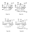
- Figures 3a and 3b illustrate a first preferred embodiment of a rotational switch.
- the first preferred embodiment "Idle On" does not power a tag in the absence of rotational energy.
- the rotational switch 114 comprises a housing 310.
- a first and a second electrode 330, 340 enter the housing 310 but are arranged at a distance from one another.
- the space between the first and the second electrode 330, 340 can be bridged by a movable conducting connector 350, which is arranged on a spring 360.
- a weight 320 is arranged on the connector 350, but this weight 320 may naturally be an integral part of the connector 350.
- Figure 3a shows the situation where no or insufficient rotational speed is imparted on the rotational switch 114.
- the connector 350 connects the first and second electrodes 330, 340 thereby causing a short circuit, which in turn means that a component arranged in parallel is not powered. In other words, when the rotational switch 114 does not rotate sufficiently, the component is idle.
- Figure 3b shows the situation where sufficient rotational speed 370 is applied to the rotational switch 114.
- the force imparted by the rotation on the weight 320 and the connector 350 is now greater than the opposite force provided by the spring 360. This breaks the contact between the first and second electrodes 330, 340, which means that the short circuit is no longer working.
- the energy provided by a power source then reaches the component, thereby powering the same.
- Figures 4a and 4b illustrate a second preferred embodiment of a rotational switch.
- the second preferred embodiment "Idle Off" powers a tag in the absence of rotational energy.
- the rotational switch 414 of the second preferred embodiment resembles that of the first preferred embodiment quite a bit.
- the housing 310, the first and second electrodes 330, 340, and the weight 320 can be practically the same.
- the connector 450 and the spring 460 are now arranged so that no connection is made in the absence of rotational force. When such force 370 is applied, however, do the weight 320 and the connector 450 press against the opposite force provided by the spring 460, so as to bridge the gap between the first and second connector 330, 340 when the rotational speed 370 is sufficient. This completes the short circuit, thereby depriving a component of the power provided by a power source.
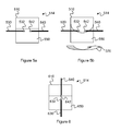
- FIGS 5a and 5b illustrate a third preferred embodiment of a rotational switch using conductive liquid.
- the third preferred embodiment can be "Idle Off” if arranged in parallel with a component and "Idle On", if arranged in series.
- the rotational switch 514 comprises a housing 510 adapted to receive a first and a second electrode 530, 540, each of which is isolated expect at, preferably, the end part 532, 542 located inside the housing 510.
- the housing 510 also comprises a conductive liquid 550, for example mercury, arranged so that it is in contact with the end parts 532, 542 regardless of the position of the rotational switch 514, as long at it is still or not subject to sufficient rotation.
- Figure 5a is for illustrative purposes only; for example, the meniscus caused by the liquids adhesion to the walls of the housing 510 is not shown.
- Figure 5b illustrates the rotational switch 514 when subjected to sufficient rotational energy 370.
- the conductive liquid 550 is now 'deformed', thus creating a liquid-free space around the end parts 532, 534, thus breaking the connection between them.
- FIG. 6 illustrates a fourth preferred embodiment of a rotational switch according to the invention.
- the fourth embodiment is relatively close to the third embodiment.
- the rotational switch 614 comprises the same features: a housing 610, a first and second electrode 640, 642 with non-isolated end parts 632, 642, and a conductive liquid 650.
- the main difference is the arrangement of the first and second electrodes 630, 640. In the fourth embodiment, they are arranged in a 'radial' way; at sufficient rotation, the second electrode 640 is completely free of liquid 650, while the first electrode 630 still is in contact therewith.
- the speed for closing or opening the contact between the first and second electrodes depends on at least the following factors that can be selected to obtain a desired value:
- the rotational switch comprises a cantilever made up of a beam having a mass at its end.
- the cantilever is arranged, during rotation, to close a circuit from a voltage source to a voltage sensitive region.
- the voltage source is autonomous, i.e. it generates electricity using only the rotation of the disk.
- the voltage sensitive region is arranged to change the optical characteristics of the surface of a DVD to ensure that the data stored in the underlying area cannot be read. It will be immediately appreciated that the use of this switch, the DVD equipped with such a switch and indeed the entire technical problem is quite distant from the present invention.
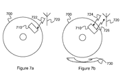
- Figures 7a and 7b illustrate a medium 700, e.g. a DVD, equipped with a tag 710 according to a preferred embodiment of the present invention.
- the medium 700 is within communication range of an antenna 720 of an external device, such as a reader for the medium 700, e.g. a DVD player.
- Figure 7a it is illustrated how the antenna 720 that sends RF energy 722 towards the antenna (not shown) of the tag 710. However, as the medium does not rotate sufficiently to power the component (not shown) of the tag 710, the tag 710 does not respond.
- Figure 7b illustrates the case when the medium 700 and its tag 710 are subject to sufficient rotational energy 730 for the rotational switch (not shown) to engage so as to power the component.
- the antenna 720 sends a RF signal 724 to the tag 710, the latter is able to process the information in the signal 724 and send a response 726.
- the information provided by the tag 710 enables use - possibly enhanced or improved - of the content on the medium 700.
- the reader sends a RF signal to the tag that returns the required information.
- the information may be a decryption key, the result of a computation performed by the tag's component (i.e. its processor), information related to the rendering of the content on the medium (such as volume, language, subtitles), or, in the case of a computer game, information about the current state of the game (such as character equipment and characteristics, available cars and race tracks).
- any kind of suitable acceleration may act on the switch to enable or disable communication.
- sufficient linear acceleration in the right direction may act upon the switch illustrated in Figures 3A, 3B, 4A and 4B .
- the present invention can avoid ambiguity for the reader, as it will receive a single response to a RF signal that it sends while having multiple receivers within communication distance. In the case of using prior art support, it would receive multiple responses from supports within communication distance of the reader.
- a tag is a convenient and economic way of manufacturing the module, as it may then be affixed to any suitable support. It is however also possible to include the tag as a part of a bigger structure, e.g. by including it in the support.
- the present invention can prevent communication collisions in environments with multiple tags, while the solution is completely transparent to the user.
Abstract
A rotation-activated electronic component, preferably a RFID tag (110) mounted on or incorporated in a support (100) that is rotated when read, e.g. a CD or DVD. The RFID tag (110) comprises an antenna (112), a rotational switch (114) and a component (116), advantageously a processor. The antenna (112) is adapted to transform received RFID signals (722) to electric energy that powers the component (116). In a preferred embodiment, the rotational switch (114) is adapted to cut the circuit unless the support (100) does not rotate at or above a certain rotational speed (370). Supports equipped with the RFID tag of the invention will thus respond only if they rotate sufficiently. This can avoid collisions in case more than one such RFID tag is within communication range of an antenna (720) of a reader. In a preferred embodiment, the information returned by the component (116) is needed for full use of the content on the support (100).
Description
- The present invention relates generally to electronic components, and more particularly to an electronic component that is activated or deactivated by rotation.
- This section is intended to introduce the reader to various aspects of art, which may be related to various aspects of the present invention that are described and/or claimed below. This discussion is believed to be helpful in providing the reader with background information to facilitate a better understanding of the various aspects of the present invention. Accordingly, it should be understood that these statements are to be read in this light, and not as admissions of prior art.
- Radio-frequency identification (RFID) uses an object, an RFID tag (hereinafter "tag"), which interacts with transmitted radio waves, for example in systems for theft prevention, supply chain management or access to buildings. A typical tag comprises at least two parts: an antenna that receives and transmits a radio-frequency (RF) signal, and an integrated circuit that stores and processes information and processes the signal. Some tags, called "active", comprise a battery and are thus autonomous, while "passive" tags have no battery and therefore have to rely on external power, often the received RF signal, in order to function properly.
- It has been proposed, for example in
WO 2006032613 , to use tags on or in digital supports such as CDs and DVDs. This may for example be done in order to protect the content on the digital support (information necessary to access the content is comprised in the tag) or to store preferences regarding the playback of the content. - While this works well in most cases, there may be problems if there are more than one tag within range of the reader. This may for example be the case when a user puts DVDs on the DVD player, since the tags on these DVDs may be as close as the one in the player. One problem with this, in particular for passive tags, is that the signal power emitted by the reader has to be shared, which may lead to decreased communication quality. A further problem is that it may be difficult for the reader to know exactly which response to take account of. For example, if one DVD returns that it should be played at volume 7 and another DVD requires volume 16, the reader would not know which volume value to choose.
- It can therefore be appreciated that there is a need for a solution that overcomes these problems and allows a reader to interact with the present tag without disturbance from other tags.
- An obvious solution to this problem would be to shield the readers, but the present invention provides a different, surprising solution to the problem, as will be seen in the description of the preferred embodiments hereinafter.
- In a first aspect, the invention is directed to an electronic device comprising communication means adapted to interact with an external device, a power source and a component adapted to process first information received from the communication means and to send second information intended for the external device to the communication means. The electronic device further comprises a switch adapted to enable communication via the communication means when it is subject to predetermined rotational speed.
- In a first preferred embodiment, the switch enables communication when the rotational speed is above a threshold value.
- In a second preferred embodiment, the component comprises a processor.
- In a third preferred embodiment, the communication means is an antenna. The electronic component is advantageously a Radio Frequency Identification (RFID) tag. It is also advantageous that the antenna is further adapted to function as the power source by transforming Radio Frequency (RF) signals to electric energy.
- In a fourth preferred embodiment, the power source is a battery.
- In a second aspect, the invention is directed to an information medium adapted to store content and comprising an electronic device according to any of the embodiments of the first aspect.
- In a first preferred embodiment, access to content stored on the information medium is enhanced or enabled by information accessible from the electronic device.
- Preferred features of the present invention will now be described, by way of non-limiting example, with reference to the accompanying drawings, in which
-
Figure 1 illustrates the basic idea of the present invention; -
Figure 2 schematically illustrates a tag according to a preferred embodiment of the present invention; -
Figures 3a and 3b illustrate a first preferred embodiment of a rotational switch; -
Figures 4a and 4b illustrate a second preferred embodiment of a rotational switch; -
Figures 5a and 5b illustrate a third preferred embodiment of a rotational switch using conductive liquid; -
Figure 6 illustrates a fourth preferred embodiment of a rotational switch according to the invention; and -
Figures 7a and 7b illustrate a medium equipped with a tag according to a preferred embodiment of the present invention - A main inventive idea of the present invention is the use of a module that is controlled by rotation. An exemplary, non-limitative use that will be used hereinafter is the activation of a tag positioned on an optical medium such as a DVD.
-
Figure 1 illustrates the basic idea of the present invention. Atag 110 is fixed to arotating support 100, i.e. a support that may rotate. Thetag 110 comprises apower source 112, arotational switch 114 and acomponent 116 that preferably has processor and memory capabilities, i.e. it comprises a processor and memory. The nature of thepower source 112 depends on whether thetag 110 is active or passive. If the tag is active, then it may for example be a battery; if the tag is passive, then it is preferably an antenna that transforms received RF signals to energy. Thecomponent 116 uses the energy from thepower source 112 to function, e.g. to process RF signals, as discussed hereinbefore. Located between thepower source 112 and thecomponent 116 is arotational switch 114. In a preferred embodiment, therotational switch 114 is arranged to cut the electric contact between thepower source 112 and thecomponent 116 unless it is subject to sufficient rotational speed, as will be further described hereinafter. In a variant embodiment, therotational switch 114 is on the contrary arranged to cut the electric contact when subject to sufficient rotational speed. It will thus be appreciated that, in the preferred embodiment, thecomponent 116 is not powered if the rotating support does not rotate quickly enough; in the variant embodiment, the opposite applies. Naturally, when thecomponent 116 is powered, it functions as a powered component of a prior art tag would do, notably communicating with a RFID reader. - The skilled person will appreciate that when the DVD is not rotating (or does not rotate at a sufficient speed), the
rotational switch 114 cuts the power supply, which for example can mean that only the DVD in the player will respond (provided that it rotates), while DVDs lying on the player will not, no matter how close to the RFID reader they come. Thus, collisions can be avoided and the signal power can be 'reserved' for a single tag. -
Figure 2 schematically illustrates a tag according to a preferred embodiment of the present invention. The tag 210, which is fixed to or part of arotating support 100, comprises acomponent 116, a power source embodied by an antenna 212, and a rotational switch 214. The antenna 212 is adapted for RF communication, i.e. transmission and reception of RF signals, and as a power supply by transforming RF signal energy to electrical energy. The rotational switch 214 comprises a first part that is movable so as to break the shortcut connection when subject to sufficient rotational energy and to establish the connection when it is not. The skilled person will appreciate that the use of a shortcut connection is preferably only used when the power source is an antenna, but not when it is a battery. - The skilled person will appreciate that it is also possible to arrange the antenna 212, the rotational switch 214 and the
component 116 in series (something that holds true for any suitable embodiment). -
Figures 3a and 3b illustrate a first preferred embodiment of a rotational switch. The first preferred embodiment, "Idle On", does not power a tag in the absence of rotational energy. - The
rotational switch 114 comprises ahousing 310. A first and asecond electrode housing 310 but are arranged at a distance from one another. The space between the first and thesecond electrode movable conducting connector 350, which is arranged on aspring 360. Aweight 320 is arranged on theconnector 350, but thisweight 320 may naturally be an integral part of theconnector 350. -
Figure 3a shows the situation where no or insufficient rotational speed is imparted on therotational switch 114. In this case, theconnector 350 connects the first andsecond electrodes rotational switch 114 does not rotate sufficiently, the component is idle. -
Figure 3b shows the situation where sufficientrotational speed 370 is applied to therotational switch 114. The force imparted by the rotation on theweight 320 and theconnector 350 is now greater than the opposite force provided by thespring 360. This breaks the contact between the first andsecond electrodes -
Figures 4a and 4b illustrate a second preferred embodiment of a rotational switch. The second preferred embodiment, "Idle Off", powers a tag in the absence of rotational energy. - The rotational switch 414 of the second preferred embodiment resembles that of the first preferred embodiment quite a bit. The
housing 310, the first andsecond electrodes weight 320 can be practically the same. However, theconnector 450 and thespring 460 are now arranged so that no connection is made in the absence of rotational force. Whensuch force 370 is applied, however, do theweight 320 and theconnector 450 press against the opposite force provided by thespring 460, so as to bridge the gap between the first andsecond connector rotational speed 370 is sufficient. This completes the short circuit, thereby depriving a component of the power provided by a power source. - The skilled person will appreciate that the expressions "Idle On" and "Idle Off" apply when the rotational switch 314, 414 is arranged in parallel with component and that the opposite holds true when the rotational switch 314, 414 is arranged in series therewith.
-
Figures 5a and 5b illustrate a third preferred embodiment of a rotational switch using conductive liquid. The third preferred embodiment can be "Idle Off" if arranged in parallel with a component and "Idle On", if arranged in series. - The
rotational switch 514 comprises ahousing 510 adapted to receive a first and asecond electrode end part housing 510. Thehousing 510 also comprises aconductive liquid 550, for example mercury, arranged so that it is in contact with theend parts rotational switch 514, as long at it is still or not subject to sufficient rotation.Figure 5a is for illustrative purposes only; for example, the meniscus caused by the liquids adhesion to the walls of thehousing 510 is not shown. -
Figure 5b illustrates therotational switch 514 when subjected to sufficientrotational energy 370. As can be seen, theconductive liquid 550 is now 'deformed', thus creating a liquid-free space around theend parts 532, 534, thus breaking the connection between them. -
Figure 6 illustrates a fourth preferred embodiment of a rotational switch according to the invention. The fourth embodiment is relatively close to the third embodiment. The rotational switch 614 comprises the same features: ahousing 610, a first andsecond electrode non-isolated end parts conductive liquid 650. The main difference is the arrangement of the first andsecond electrodes second electrode 640 is completely free ofliquid 650, while thefirst electrode 630 still is in contact therewith. - The speed for closing or opening the contact between the first and second electrodes depends on at least the following factors that can be selected to obtain a desired value:
- size of the housing,
- fluid amount and viscosity
- size and position of the electrodes
- distance of the rotational switch from the rotation centre.
- A further example of a rotational switch is found in
US 2006/0250923 . The rotational switch comprises a cantilever made up of a beam having a mass at its end. The cantilever is arranged, during rotation, to close a circuit from a voltage source to a voltage sensitive region. The voltage source is autonomous, i.e. it generates electricity using only the rotation of the disk. The voltage sensitive region is arranged to change the optical characteristics of the surface of a DVD to ensure that the data stored in the underlying area cannot be read. It will be immediately appreciated that the use of this switch, the DVD equipped with such a switch and indeed the entire technical problem is quite distant from the present invention. -
Figures 7a and 7b illustrate a medium 700, e.g. a DVD, equipped with atag 710 according to a preferred embodiment of the present invention. The medium 700 is within communication range of anantenna 720 of an external device, such as a reader for the medium 700, e.g. a DVD player. - In
Figure 7a , it is illustrated how theantenna 720 that sendsRF energy 722 towards the antenna (not shown) of thetag 710. However, as the medium does not rotate sufficiently to power the component (not shown) of thetag 710, thetag 710 does not respond. -
Figure 7b , on the other hand, illustrates the case when the medium 700 and itstag 710 are subject to sufficientrotational energy 730 for the rotational switch (not shown) to engage so as to power the component. In this case, when theantenna 720 sends aRF signal 724 to thetag 710, the latter is able to process the information in thesignal 724 and send aresponse 726. - In a preferred embodiment, the information provided by the
tag 710 enables use - possibly enhanced or improved - of the content on the medium 700. To obtain this information, the reader sends a RF signal to the tag that returns the required information. For example, the information may be a decryption key, the result of a computation performed by the tag's component (i.e. its processor), information related to the rendering of the content on the medium (such as volume, language, subtitles), or, in the case of a computer game, information about the current state of the game (such as character equipment and characteristics, available cars and race tracks...). - It will be appreciated that other types of movement than rotational may be envisaged; any kind of suitable acceleration may act on the switch to enable or disable communication. For example, sufficient linear acceleration in the right direction may act upon the switch illustrated in
Figures 3A, 3B, 4A and 4B . - It will be appreciated that the present invention can avoid ambiguity for the reader, as it will receive a single response to a RF signal that it sends while having multiple receivers within communication distance. In the case of using prior art support, it would receive multiple responses from supports within communication distance of the reader.
- It will be appreciated that a tag is a convenient and economic way of manufacturing the module, as it may then be affixed to any suitable support. It is however also possible to include the tag as a part of a bigger structure, e.g. by including it in the support.
- It will further be appreciated that the present invention can prevent communication collisions in environments with multiple tags, while the solution is completely transparent to the user.
- Each feature disclosed in the description and (where appropriate) the claims and drawings may be provided independently or in any appropriate combination. Reference numerals appearing in the claims are by way of illustration only and shall have no limiting effect on the scope of the claims.
Claims (9)
- An electronic device (110) comprising communication means (112) adapted to interact with an external device, a power source (112) and a component (116) adapted to process first information received from the communication means (112) and to send second information to the communication means (112), the second information being intended for the external device, the electronic device being characterized in that it further comprises a switch (114) adapted to enable communication via the communication means (112) when it is subject to predetermined rotational speed (370).
- The electronic device of claim 1, wherein the switch (114) enables communication when the rotational speed (370) is above a threshold value.
- The electronic device of claim 1, wherein the component (116) comprises a processor.
- The electronic device of claim 1, wherein the communication means (112) is an antenna.
- The electronic device of claim 4, wherein the electronic component (110) is a Radio Frequency Identification (RFID) tag.
- The electronic device of claim 4, wherein the antenna (112) is further adapted to function as the power source (112) by transforming Radio Frequency (RF) signals to electric energy.
- The electronic device of claim 1, wherein the power source (112) is a battery.
- An information medium (100) adapted to store content and comprising an electronic device (110) according to any of claims 1 to 7.
- The information medium of claim 8, wherein access to content stored on the information medium (100) is enhanced or enabled by information accessible from the electronic device (110).
Priority Applications (8)
| Application Number | Priority Date | Filing Date | Title |
|---|---|---|---|
| EP09305533A EP2267633A1 (en) | 2009-06-11 | 2009-06-11 | Rotation-activated electronic component |
| EP10162404.7A EP2267636B1 (en) | 2009-06-11 | 2010-05-10 | Rotation-activated electronic component |
| TW099116210A TWI507997B (en) | 2009-06-11 | 2010-05-21 | Rotation-activated electronic component |
| BRPI1001860-3A BRPI1001860A2 (en) | 2009-06-11 | 2010-06-07 | rotation-activated electronic component |
| KR1020100053893A KR20100133306A (en) | 2009-06-11 | 2010-06-08 | Rotation-activated electronic component |
| JP2010131947A JP5535776B2 (en) | 2009-06-11 | 2010-06-09 | Electronic element |
| CN2010102024002A CN101923628A (en) | 2009-06-11 | 2010-06-09 | Rotation-activated electronic component |
| US12/797,678 US8436717B2 (en) | 2009-06-11 | 2010-06-10 | Rotation-activated electronic component |
Applications Claiming Priority (1)
| Application Number | Priority Date | Filing Date | Title |
|---|---|---|---|
| EP09305533A EP2267633A1 (en) | 2009-06-11 | 2009-06-11 | Rotation-activated electronic component |
Publications (1)
| Publication Number | Publication Date |
|---|---|
| EP2267633A1 true EP2267633A1 (en) | 2010-12-29 |
Family
ID=41210870
Family Applications (2)
| Application Number | Title | Priority Date | Filing Date |
|---|---|---|---|
| EP09305533A Withdrawn EP2267633A1 (en) | 2009-06-11 | 2009-06-11 | Rotation-activated electronic component |
| EP10162404.7A Not-in-force EP2267636B1 (en) | 2009-06-11 | 2010-05-10 | Rotation-activated electronic component |
Family Applications After (1)
| Application Number | Title | Priority Date | Filing Date |
|---|---|---|---|
| EP10162404.7A Not-in-force EP2267636B1 (en) | 2009-06-11 | 2010-05-10 | Rotation-activated electronic component |
Country Status (7)
| Country | Link |
|---|---|
| US (1) | US8436717B2 (en) |
| EP (2) | EP2267633A1 (en) |
| JP (1) | JP5535776B2 (en) |
| KR (1) | KR20100133306A (en) |
| CN (1) | CN101923628A (en) |
| BR (1) | BRPI1001860A2 (en) |
| TW (1) | TWI507997B (en) |
Families Citing this family (4)
| Publication number | Priority date | Publication date | Assignee | Title |
|---|---|---|---|---|
| DE102011014411A1 (en) * | 2011-03-18 | 2012-09-20 | Giesecke & Devrient Gmbh | Portable data carrier with nanogenerator |
| WO2017023735A1 (en) * | 2015-07-31 | 2017-02-09 | Stanley Industrial And Automotive, Llc. | Rotary rfid switch |
| CN108597206A (en) * | 2018-06-06 | 2018-09-28 | 安徽启电自动化科技有限公司 | A kind of rotating environment electricity pick-up device |
| CN112926913B (en) * | 2021-02-02 | 2022-11-01 | 国网河北省电力有限公司沧州供电分公司 | Electronic material warehouse management tag, reading device, searching method and system |
Citations (8)
| Publication number | Priority date | Publication date | Assignee | Title |
|---|---|---|---|---|
| US5483827A (en) * | 1994-06-03 | 1996-01-16 | Computer Methods Corporation | Active integrated circuit transponder and sensor apparatus for sensing and transmitting vehicle tire parameter data |
| US6150921A (en) * | 1996-10-17 | 2000-11-21 | Pinpoint Corporation | Article tracking system |
| US6357005B1 (en) * | 1996-07-26 | 2002-03-12 | Oberthur Card Systems Sa | System for the secure CD-ROM storage of data |
| WO2006032613A2 (en) | 2004-09-21 | 2006-03-30 | Thomson Licensing | Method and apparatus for accessing protected data |
| US20060250923A1 (en) | 2005-05-09 | 2006-11-09 | Searete Llc, A Limited Liability Corporation Of The State Of Delaware | Method and system for fluid mediated disk activation and deactivation |
| DE102006043505A1 (en) * | 2006-05-22 | 2007-11-29 | Continental Teves Ag & Co. Ohg | Tire module and method for detecting wheel and / or tire condition sizes |
| US20080200844A1 (en) * | 2007-02-19 | 2008-08-21 | Manuel Millahn | Surgical device with an impact detector |
| US20080307884A1 (en) * | 2006-09-08 | 2008-12-18 | Siemens Aktiengesellschaft | Non-contact shock sensor |
Family Cites Families (17)
| Publication number | Priority date | Publication date | Assignee | Title |
|---|---|---|---|---|
| US6902111B2 (en) * | 1998-11-12 | 2005-06-07 | Wenyu Han | Method and apparatus for impeding the counterfeiting of discs |
| US6678824B1 (en) * | 1999-11-02 | 2004-01-13 | Agere Systems Inc. | Application usage time limiter |
| JP2003346107A (en) * | 2002-05-27 | 2003-12-05 | Totoku Electric Co Ltd | Wireless article management tag and article management system |
| US7107009B2 (en) * | 2002-06-26 | 2006-09-12 | Nokia Corporation | Method, system and computer program product for personalizing the functionality of a personal communication device |
| US7072697B2 (en) * | 2002-10-22 | 2006-07-04 | Nokia Corporation | Method and device for transponder aided wake-up of a low power radio device by a wake-up event |
| US7563748B2 (en) | 2003-06-23 | 2009-07-21 | Cognis Ip Management Gmbh | Alcohol alkoxylate carriers for pesticide active ingredients |
| JP2005190514A (en) * | 2003-12-24 | 2005-07-14 | Dainippon Printing Co Ltd | Digital recording medium and reproducing device |
| KR100630898B1 (en) * | 2004-02-13 | 2006-10-04 | (주)에스디시스템 | Radio Frequency Identity Tag for reducing the power consumption |
| TWI264705B (en) * | 2004-04-27 | 2006-10-21 | Asustek Comp Inc | A disk player with an adjustable rotating speed and a method of the same |
| US7948381B2 (en) * | 2004-04-30 | 2011-05-24 | Binforma Group Limited Liability Company | Reversibly deactivating a radio frequency identification data tag |
| US7505784B2 (en) * | 2005-09-26 | 2009-03-17 | Barbera Melvin A | Safety features for portable electronic device |
| US9285471B2 (en) * | 2005-11-21 | 2016-03-15 | Hewlett-Packard Development Company, L.P. | Method and apparatus for localization of RFID tags |
| US20070159329A1 (en) * | 2005-12-02 | 2007-07-12 | Shmuel Silverman | Information protection using a printed electronic circuit and laser impression |
| US7446658B2 (en) * | 2006-03-09 | 2008-11-04 | Avago Technologies General Ip (Singapore) Pte. Ltd. | Identification (ID) system and method of operation thereof |
| US8131263B2 (en) * | 2006-12-06 | 2012-03-06 | Microsoft Corporation | Backup media with wireless identifications tags |
| US20080157974A1 (en) * | 2006-12-27 | 2008-07-03 | Gregory Jensen Boss | Method of disabling and enabling radio frequency identification after a predefined time period or event |
| US9324071B2 (en) * | 2008-03-20 | 2016-04-26 | Visa U.S.A. Inc. | Powering financial transaction token with onboard power source |
-
2009
- 2009-06-11 EP EP09305533A patent/EP2267633A1/en not_active Withdrawn
-
2010
- 2010-05-10 EP EP10162404.7A patent/EP2267636B1/en not_active Not-in-force
- 2010-05-21 TW TW099116210A patent/TWI507997B/en not_active IP Right Cessation
- 2010-06-07 BR BRPI1001860-3A patent/BRPI1001860A2/en not_active IP Right Cessation
- 2010-06-08 KR KR1020100053893A patent/KR20100133306A/en not_active Application Discontinuation
- 2010-06-09 CN CN2010102024002A patent/CN101923628A/en active Pending
- 2010-06-09 JP JP2010131947A patent/JP5535776B2/en not_active Expired - Fee Related
- 2010-06-10 US US12/797,678 patent/US8436717B2/en not_active Expired - Fee Related
Patent Citations (9)
| Publication number | Priority date | Publication date | Assignee | Title |
|---|---|---|---|---|
| US5483827A (en) * | 1994-06-03 | 1996-01-16 | Computer Methods Corporation | Active integrated circuit transponder and sensor apparatus for sensing and transmitting vehicle tire parameter data |
| US6357005B1 (en) * | 1996-07-26 | 2002-03-12 | Oberthur Card Systems Sa | System for the secure CD-ROM storage of data |
| US6150921A (en) * | 1996-10-17 | 2000-11-21 | Pinpoint Corporation | Article tracking system |
| WO2006032613A2 (en) | 2004-09-21 | 2006-03-30 | Thomson Licensing | Method and apparatus for accessing protected data |
| US20080199006A1 (en) * | 2004-09-21 | 2008-08-21 | Thomson Licensing | Method and Apparatus for Accessing Proteceted Data |
| US20060250923A1 (en) | 2005-05-09 | 2006-11-09 | Searete Llc, A Limited Liability Corporation Of The State Of Delaware | Method and system for fluid mediated disk activation and deactivation |
| DE102006043505A1 (en) * | 2006-05-22 | 2007-11-29 | Continental Teves Ag & Co. Ohg | Tire module and method for detecting wheel and / or tire condition sizes |
| US20080307884A1 (en) * | 2006-09-08 | 2008-12-18 | Siemens Aktiengesellschaft | Non-contact shock sensor |
| US20080200844A1 (en) * | 2007-02-19 | 2008-08-21 | Manuel Millahn | Surgical device with an impact detector |
Also Published As
| Publication number | Publication date |
|---|---|
| JP5535776B2 (en) | 2014-07-02 |
| TWI507997B (en) | 2015-11-11 |
| EP2267636A2 (en) | 2010-12-29 |
| KR20100133306A (en) | 2010-12-21 |
| TW201044281A (en) | 2010-12-16 |
| BRPI1001860A2 (en) | 2011-07-05 |
| JP2010287234A (en) | 2010-12-24 |
| US8436717B2 (en) | 2013-05-07 |
| US20100315922A1 (en) | 2010-12-16 |
| EP2267636B1 (en) | 2014-07-30 |
| CN101923628A (en) | 2010-12-22 |
| EP2267636A3 (en) | 2012-06-13 |
Similar Documents
| Publication | Publication Date | Title |
|---|---|---|
| EP2267633A1 (en) | Rotation-activated electronic component | |
| US20090322346A1 (en) | Motherboard test system and test method thereof | |
| CN103942581A (en) | Electronic device for recognizing erroneous insertion of card, and operating method thereof | |
| CN113448389A (en) | Accessory device for an electronic device | |
| CN101377829B (en) | Card-type peripheral device | |
| CN103164173A (en) | Memory card and data storage method | |
| WO2017011311A1 (en) | Electronic data storage device with multiple configurable data storage mediums | |
| EP2360627B1 (en) | Rotation-activated electronic component with time-limited use | |
| EP3298358B1 (en) | Improvements in or relating to level switches | |
| EP1936543A1 (en) | Radio frequency identification | |
| JP2007072706A (en) | Sim holder | |
| JP2007233672A (en) | Electronic appliance and storage medium reader housed in electronic appliance | |
| GB2593623A (en) | A first-aid kit container dispensing system | |
| US20170322601A1 (en) | Apparatus for configuring a memory drive device | |
| CN108449436B (en) | Monitoring device and monitoring system | |
| CN201035603Y (en) | Electronic label of compact disk | |
| US20230152866A1 (en) | Systems and methods for use of magnets to retain and eject computing device expansion modules | |
| EP2073176A1 (en) | Portable electronic system with controle of the energy consumption of a system element | |
| JP2005174457A (en) | Information storage device and information equipment | |
| US20090066512A1 (en) | Transponder device | |
| KR200420916Y1 (en) | RFID tag and RFID system comprising the same | |
| CN109992533A (en) | A kind of data destruction device | |
| KR20070034859A (en) | USB connector with infrared communication unit | |
| JP2016218828A (en) | Non-contact communication device | |
| JP2007042256A (en) | Disk drive unit |
Legal Events
| Date | Code | Title | Description |
|---|---|---|---|
| PUAI | Public reference made under article 153(3) epc to a published international application that has entered the european phase |
Free format text: ORIGINAL CODE: 0009012 |
|
| AK | Designated contracting states |
Kind code of ref document: A1 Designated state(s): AT BE BG CH CY CZ DE DK EE ES FI FR GB GR HR HU IE IS IT LI LT LU LV MC MK MT NL NO PL PT RO SE SI SK TR |
|
| AX | Request for extension of the european patent |
Extension state: AL BA RS |
|
| STAA | Information on the status of an ep patent application or granted ep patent |
Free format text: STATUS: THE APPLICATION IS DEEMED TO BE WITHDRAWN |
|
| 18D | Application deemed to be withdrawn |
Effective date: 20110630 |