EP2269718A2 - Device for mixing and applying bone cement - Google Patents
Device for mixing and applying bone cement Download PDFInfo
- Publication number
- EP2269718A2 EP2269718A2 EP10005897A EP10005897A EP2269718A2 EP 2269718 A2 EP2269718 A2 EP 2269718A2 EP 10005897 A EP10005897 A EP 10005897A EP 10005897 A EP10005897 A EP 10005897A EP 2269718 A2 EP2269718 A2 EP 2269718A2
- Authority
- EP
- European Patent Office
- Prior art keywords
- piston
- bone cement
- mixing
- sterilization
- monomer
- Prior art date
- Legal status (The legal status is an assumption and is not a legal conclusion. Google has not performed a legal analysis and makes no representation as to the accuracy of the status listed.)
- Granted
Links
- 238000002156 mixing Methods 0.000 title claims abstract description 121
- 239000002639 bone cement Substances 0.000 title claims abstract description 102
- 230000001954 sterilising effect Effects 0.000 claims abstract description 70
- 238000004659 sterilization and disinfection Methods 0.000 claims abstract description 64
- 238000007789 sealing Methods 0.000 claims abstract description 50
- 239000000843 powder Substances 0.000 claims abstract description 47
- 239000000178 monomer Substances 0.000 claims abstract description 45
- 239000011230 binding agent Substances 0.000 claims abstract description 23
- 230000008878 coupling Effects 0.000 claims description 6
- 238000010168 coupling process Methods 0.000 claims description 6
- 238000005859 coupling reaction Methods 0.000 claims description 6
- 238000011010 flushing procedure Methods 0.000 claims description 6
- 239000003206 sterilizing agent Substances 0.000 claims description 6
- 239000011521 glass Substances 0.000 claims description 3
- 239000004568 cement Substances 0.000 description 18
- 238000007599 discharging Methods 0.000 description 8
- IAYPIBMASNFSPL-UHFFFAOYSA-N Ethylene oxide Chemical compound C1CO1 IAYPIBMASNFSPL-UHFFFAOYSA-N 0.000 description 6
- VVQNEPGJFQJSBK-UHFFFAOYSA-N Methyl methacrylate Chemical compound COC(=O)C(C)=C VVQNEPGJFQJSBK-UHFFFAOYSA-N 0.000 description 5
- 239000007788 liquid Substances 0.000 description 5
- 239000002245 particle Substances 0.000 description 4
- 229920003229 poly(methyl methacrylate) Polymers 0.000 description 4
- 239000004926 polymethyl methacrylate Substances 0.000 description 4
- 239000012530 fluid Substances 0.000 description 3
- 229920000642 polymer Polymers 0.000 description 3
- OMPJBNCRMGITSC-UHFFFAOYSA-N Benzoylperoxide Chemical compound C=1C=CC=CC=1C(=O)OOC(=O)C1=CC=CC=C1 OMPJBNCRMGITSC-UHFFFAOYSA-N 0.000 description 2
- BAPJBEWLBFYGME-UHFFFAOYSA-N Methyl acrylate Chemical compound COC(=O)C=C BAPJBEWLBFYGME-UHFFFAOYSA-N 0.000 description 2
- PPBRXRYQALVLMV-UHFFFAOYSA-N Styrene Chemical compound C=CC1=CC=CC=C1 PPBRXRYQALVLMV-UHFFFAOYSA-N 0.000 description 2
- 239000012190 activator Substances 0.000 description 2
- 239000003570 air Substances 0.000 description 2
- 244000052616 bacterial pathogen Species 0.000 description 2
- 235000019400 benzoyl peroxide Nutrition 0.000 description 2
- 210000000988 bone and bone Anatomy 0.000 description 2
- 238000011109 contamination Methods 0.000 description 2
- 238000011161 development Methods 0.000 description 2
- 230000018109 developmental process Effects 0.000 description 2
- GYVGXEWAOAAJEU-UHFFFAOYSA-N n,n,4-trimethylaniline Chemical compound CN(C)C1=CC=C(C)C=C1 GYVGXEWAOAAJEU-UHFFFAOYSA-N 0.000 description 2
- 238000006116 polymerization reaction Methods 0.000 description 2
- 239000000565 sealant Substances 0.000 description 2
- 241000906034 Orthops Species 0.000 description 1
- 239000012080 ambient air Substances 0.000 description 1
- 239000003795 chemical substances by application Substances 0.000 description 1
- 239000000356 contaminant Substances 0.000 description 1
- 230000001419 dependent effect Effects 0.000 description 1
- 230000001687 destabilization Effects 0.000 description 1
- 238000006073 displacement reaction Methods 0.000 description 1
- 230000000694 effects Effects 0.000 description 1
- 238000005516 engineering process Methods 0.000 description 1
- 230000007613 environmental effect Effects 0.000 description 1
- 238000001125 extrusion Methods 0.000 description 1
- 210000000501 femur body Anatomy 0.000 description 1
- 239000011440 grout Substances 0.000 description 1
- 239000012535 impurity Substances 0.000 description 1
- 239000003999 initiator Substances 0.000 description 1
- 238000000034 method Methods 0.000 description 1
- 239000000203 mixture Substances 0.000 description 1
- 238000004806 packaging method and process Methods 0.000 description 1
- 238000010526 radical polymerization reaction Methods 0.000 description 1
- 230000002441 reversible effect Effects 0.000 description 1
- 238000000926 separation method Methods 0.000 description 1
- 238000010557 suspension polymerization reaction Methods 0.000 description 1
- 230000008961 swelling Effects 0.000 description 1
- 230000001960 triggered effect Effects 0.000 description 1
Images

Classifications
-
- B—PERFORMING OPERATIONS; TRANSPORTING
- B01—PHYSICAL OR CHEMICAL PROCESSES OR APPARATUS IN GENERAL
- B01F—MIXING, e.g. DISSOLVING, EMULSIFYING OR DISPERSING
- B01F31/00—Mixers with shaking, oscillating, or vibrating mechanisms
- B01F31/44—Mixers with shaking, oscillating, or vibrating mechanisms with stirrers performing an oscillatory, vibratory or shaking movement
- B01F31/441—Mixers with shaking, oscillating, or vibrating mechanisms with stirrers performing an oscillatory, vibratory or shaking movement performing a rectilinear reciprocating movement
-
- A—HUMAN NECESSITIES
- A61—MEDICAL OR VETERINARY SCIENCE; HYGIENE
- A61B—DIAGNOSIS; SURGERY; IDENTIFICATION
- A61B17/00—Surgical instruments, devices or methods, e.g. tourniquets
- A61B17/56—Surgical instruments or methods for treatment of bones or joints; Devices specially adapted therefor
- A61B17/58—Surgical instruments or methods for treatment of bones or joints; Devices specially adapted therefor for osteosynthesis, e.g. bone plates, screws, setting implements or the like
- A61B17/88—Osteosynthesis instruments; Methods or means for implanting or extracting internal or external fixation devices
- A61B17/8802—Equipment for handling bone cement or other fluid fillers
- A61B17/8805—Equipment for handling bone cement or other fluid fillers for introducing fluid filler into bone or extracting it
- A61B17/8825—Equipment for handling bone cement or other fluid fillers for introducing fluid filler into bone or extracting it characterised by syringe details
-
- A—HUMAN NECESSITIES
- A61—MEDICAL OR VETERINARY SCIENCE; HYGIENE
- A61B—DIAGNOSIS; SURGERY; IDENTIFICATION
- A61B17/00—Surgical instruments, devices or methods, e.g. tourniquets
- A61B17/56—Surgical instruments or methods for treatment of bones or joints; Devices specially adapted therefor
- A61B17/58—Surgical instruments or methods for treatment of bones or joints; Devices specially adapted therefor for osteosynthesis, e.g. bone plates, screws, setting implements or the like
- A61B17/88—Osteosynthesis instruments; Methods or means for implanting or extracting internal or external fixation devices
- A61B17/8802—Equipment for handling bone cement or other fluid fillers
- A61B17/8805—Equipment for handling bone cement or other fluid fillers for introducing fluid filler into bone or extracting it
- A61B17/8827—Equipment for handling bone cement or other fluid fillers for introducing fluid filler into bone or extracting it with filtering, degassing, venting or pressure relief means
-
- B—PERFORMING OPERATIONS; TRANSPORTING
- B01—PHYSICAL OR CHEMICAL PROCESSES OR APPARATUS IN GENERAL
- B01F—MIXING, e.g. DISSOLVING, EMULSIFYING OR DISPERSING
- B01F33/00—Other mixers; Mixing plants; Combinations of mixers
- B01F33/50—Movable or transportable mixing devices or plants
- B01F33/501—Movable mixing devices, i.e. readily shifted or displaced from one place to another, e.g. portable during use
- B01F33/5011—Movable mixing devices, i.e. readily shifted or displaced from one place to another, e.g. portable during use portable during use, e.g. hand-held
-
- B—PERFORMING OPERATIONS; TRANSPORTING
- B01—PHYSICAL OR CHEMICAL PROCESSES OR APPARATUS IN GENERAL
- B01F—MIXING, e.g. DISSOLVING, EMULSIFYING OR DISPERSING
- B01F33/00—Other mixers; Mixing plants; Combinations of mixers
- B01F33/70—Mixers specially adapted for working at sub- or super-atmospheric pressure, e.g. combined with de-foaming
-
- B—PERFORMING OPERATIONS; TRANSPORTING
- B01—PHYSICAL OR CHEMICAL PROCESSES OR APPARATUS IN GENERAL
- B01F—MIXING, e.g. DISSOLVING, EMULSIFYING OR DISPERSING
- B01F35/00—Accessories for mixers; Auxiliary operations or auxiliary devices; Parts or details of general application
- B01F35/10—Maintenance of mixers
- B01F35/145—Washing or cleaning mixers not provided for in other groups in this subclass; Inhibiting build-up of material on machine parts using other means
- B01F35/146—Working under sterile conditions; Sterilizing the mixer or parts thereof
-
- B—PERFORMING OPERATIONS; TRANSPORTING
- B01—PHYSICAL OR CHEMICAL PROCESSES OR APPARATUS IN GENERAL
- B01F—MIXING, e.g. DISSOLVING, EMULSIFYING OR DISPERSING
- B01F35/00—Accessories for mixers; Auxiliary operations or auxiliary devices; Parts or details of general application
- B01F35/71—Feed mechanisms
- B01F35/713—Feed mechanisms comprising breaking packages or parts thereof, e.g. piercing or opening sealing elements between compartments or cartridges
-
- B—PERFORMING OPERATIONS; TRANSPORTING
- B01—PHYSICAL OR CHEMICAL PROCESSES OR APPARATUS IN GENERAL
- B01F—MIXING, e.g. DISSOLVING, EMULSIFYING OR DISPERSING
- B01F35/00—Accessories for mixers; Auxiliary operations or auxiliary devices; Parts or details of general application
- B01F35/71—Feed mechanisms
- B01F35/717—Feed mechanisms characterised by the means for feeding the components to the mixer
- B01F35/7174—Feed mechanisms characterised by the means for feeding the components to the mixer using pistons, plungers or syringes
-
- B—PERFORMING OPERATIONS; TRANSPORTING
- B01—PHYSICAL OR CHEMICAL PROCESSES OR APPARATUS IN GENERAL
- B01F—MIXING, e.g. DISSOLVING, EMULSIFYING OR DISPERSING
- B01F35/00—Accessories for mixers; Auxiliary operations or auxiliary devices; Parts or details of general application
- B01F35/71—Feed mechanisms
- B01F35/717—Feed mechanisms characterised by the means for feeding the components to the mixer
- B01F35/718—Feed mechanisms characterised by the means for feeding the components to the mixer using vacuum, under pressure in a closed receptacle or circuit system
-
- B—PERFORMING OPERATIONS; TRANSPORTING
- B01—PHYSICAL OR CHEMICAL PROCESSES OR APPARATUS IN GENERAL
- B01F—MIXING, e.g. DISSOLVING, EMULSIFYING OR DISPERSING
- B01F35/00—Accessories for mixers; Auxiliary operations or auxiliary devices; Parts or details of general application
- B01F35/71—Feed mechanisms
- B01F35/717—Feed mechanisms characterised by the means for feeding the components to the mixer
- B01F35/71805—Feed mechanisms characterised by the means for feeding the components to the mixer using valves, gates, orifices or openings
-
- B—PERFORMING OPERATIONS; TRANSPORTING
- B01—PHYSICAL OR CHEMICAL PROCESSES OR APPARATUS IN GENERAL
- B01F—MIXING, e.g. DISSOLVING, EMULSIFYING OR DISPERSING
- B01F35/00—Accessories for mixers; Auxiliary operations or auxiliary devices; Parts or details of general application
- B01F35/75—Discharge mechanisms
- B01F35/754—Discharge mechanisms characterised by the means for discharging the components from the mixer
- B01F35/75425—Discharge mechanisms characterised by the means for discharging the components from the mixer using pistons or plungers
- B01F35/754251—Discharge mechanisms characterised by the means for discharging the components from the mixer using pistons or plungers reciprocating in the mixing receptacle
-
- B—PERFORMING OPERATIONS; TRANSPORTING
- B01—PHYSICAL OR CHEMICAL PROCESSES OR APPARATUS IN GENERAL
- B01F—MIXING, e.g. DISSOLVING, EMULSIFYING OR DISPERSING
- B01F35/00—Accessories for mixers; Auxiliary operations or auxiliary devices; Parts or details of general application
- B01F35/75—Discharge mechanisms
- B01F35/754—Discharge mechanisms characterised by the means for discharging the components from the mixer
- B01F35/7547—Discharge mechanisms characterised by the means for discharging the components from the mixer using valves, gates, orifices or openings
-
- A—HUMAN NECESSITIES
- A61—MEDICAL OR VETERINARY SCIENCE; HYGIENE
- A61B—DIAGNOSIS; SURGERY; IDENTIFICATION
- A61B17/00—Surgical instruments, devices or methods, e.g. tourniquets
- A61B17/56—Surgical instruments or methods for treatment of bones or joints; Devices specially adapted therefor
- A61B17/58—Surgical instruments or methods for treatment of bones or joints; Devices specially adapted therefor for osteosynthesis, e.g. bone plates, screws, setting implements or the like
- A61B17/88—Osteosynthesis instruments; Methods or means for implanting or extracting internal or external fixation devices
- A61B17/8802—Equipment for handling bone cement or other fluid fillers
- A61B17/8833—Osteosynthesis tools specially adapted for handling bone cement or fluid fillers; Means for supplying bone cement or fluid fillers to introducing tools, e.g. cartridge handling means
- A61B2017/8838—Osteosynthesis tools specially adapted for handling bone cement or fluid fillers; Means for supplying bone cement or fluid fillers to introducing tools, e.g. cartridge handling means for mixing bone cement or fluid fillers
-
- A—HUMAN NECESSITIES
- A61—MEDICAL OR VETERINARY SCIENCE; HYGIENE
- A61F—FILTERS IMPLANTABLE INTO BLOOD VESSELS; PROSTHESES; DEVICES PROVIDING PATENCY TO, OR PREVENTING COLLAPSING OF, TUBULAR STRUCTURES OF THE BODY, e.g. STENTS; ORTHOPAEDIC, NURSING OR CONTRACEPTIVE DEVICES; FOMENTATION; TREATMENT OR PROTECTION OF EYES OR EARS; BANDAGES, DRESSINGS OR ABSORBENT PADS; FIRST-AID KITS
- A61F2/00—Filters implantable into blood vessels; Prostheses, i.e. artificial substitutes or replacements for parts of the body; Appliances for connecting them with the body; Devices providing patency to, or preventing collapsing of, tubular structures of the body, e.g. stents
- A61F2/02—Prostheses implantable into the body
- A61F2/30—Joints
- A61F2/46—Special tools or methods for implanting or extracting artificial joints, accessories, bone grafts or substitutes, or particular adaptations therefor
- A61F2002/4631—Special tools or methods for implanting or extracting artificial joints, accessories, bone grafts or substitutes, or particular adaptations therefor the prosthesis being specially adapted for being cemented
-
- A—HUMAN NECESSITIES
- A61—MEDICAL OR VETERINARY SCIENCE; HYGIENE
- A61F—FILTERS IMPLANTABLE INTO BLOOD VESSELS; PROSTHESES; DEVICES PROVIDING PATENCY TO, OR PREVENTING COLLAPSING OF, TUBULAR STRUCTURES OF THE BODY, e.g. STENTS; ORTHOPAEDIC, NURSING OR CONTRACEPTIVE DEVICES; FOMENTATION; TREATMENT OR PROTECTION OF EYES OR EARS; BANDAGES, DRESSINGS OR ABSORBENT PADS; FIRST-AID KITS
- A61F2/00—Filters implantable into blood vessels; Prostheses, i.e. artificial substitutes or replacements for parts of the body; Appliances for connecting them with the body; Devices providing patency to, or preventing collapsing of, tubular structures of the body, e.g. stents
- A61F2/02—Prostheses implantable into the body
- A61F2/30—Joints
- A61F2/46—Special tools or methods for implanting or extracting artificial joints, accessories, bone grafts or substitutes, or particular adaptations therefor
- A61F2002/4685—Special tools or methods for implanting or extracting artificial joints, accessories, bone grafts or substitutes, or particular adaptations therefor by means of vacuum
Definitions
- the invention relates to a device for mixing and discharging bone cement according to the features of the preamble of claim 1, with a mixing cylinder, in which a mixing piston is arranged, wherein the mixing piston is axially movable by means of a seal rod led out sealed at a first cylinder end. Furthermore, the invention relates to a bone cement system with the features of claim 11.
- PMMA bone cements are based on the fundamental work of Sir Charnley ( Charnley, J .: Anchorage of the femoral head prosthesis of the shaft of the femur. J. Bone Joint Surg. 42 (1960) 28-30 .).
- PMMA bone cements consist of a liquid monomer component and a powder component.
- the monomer component generally contains the monomer methyl methacrylate and an activator (N, N-dimethyl-p-toluidine) dissolved therein.
- the powder component also referred to as bone cement powder, comprises one or more polymers based on methyl methacrylate and comonomers such as styrene, methyl acrylate or similar monomers by polymerization, preferably suspension polymerization, an X-ray opaque and the initiator dibenzoyl peroxide.
- comonomers such as styrene, methyl acrylate or similar monomers by polymerization, preferably suspension polymerization, an X-ray opaque and the initiator dibenzoyl peroxide.
- swelling of the polymers of the powder component in methyl methacrylate produces a plastically deformable dough, the actual bone cement.
- the activator Upon mixing the powder component with the monomer component, the activator reacts N, N-dimethyl-p-toluidine with dibenzoyl peroxide to form radicals.
- the radicals formed initiate the radical polymerization of the methyl methacrylate.
- Vacuum mixed bone cements have significantly reduced porosity and therefore exhibit improved mechanical properties.
- a variety of vacuum cementing systems have been disclosed, of which the following are by way of example: US 6,033,105 A . US 5,624,184 A . US 4,671,263 A . US 4,973,168 A . US 5,100,241 A . WO 99/67015 Al . EP 1 020 167 A2 . US 5,586,821 A . EP 1 016 452 A2 . DE 36 40 279 A1 . WO 94/26403 A1 . EP 0 692 229 A1 . EP 1 005 901 A2 . US 5,344,232 A , Also describes the EP 1 920 738 A2 a vacuum cementing system that allows bone cements to be created.
- an axially movable two-part piston system is arranged in the region of the first cylinder end, wherein the piston system has a sterilization piston and a sealing piston, the sterilization piston and the sealing piston are axially movable separately on the actuating rod, the sterilization piston closes the mixing cylinder gas-permeable and the sealing piston seals the mixing cylinder gas-tight.
- the sterilization piston is arranged between the mixing piston and the sealing piston on the actuating rod. This arrangement of the two parts of the piston system ensures that a sterilizing agent can flow into the mixing cylinder without being hindered by the sealing piston. Only then is the sealing piston applied to the sterilization piston, thus combining the two-part piston system.
- the essence of the invention described herein is to close one end of the mixing cylinder with a two-part piston system.
- the two parts of the piston system can be moved axially independently on the actuating rod.
- the sterilization piston closes the mixing cylinder in a gas-permeable manner.
- a sterilizing agent can flow into the mixing cylinder and sterilize the bone cement powder stored there.
- the sealing piston of the piston system then allows a gas-tight completion of the mixing cylinder to connect it with a vacuum and to suck a binder for the bone cement powder in the mixing flask.
- the two-part piston system is characterized in that the sterilization piston gas-permeable completion of the mixing cylinder to allow flushing a bone cement powder with a sterilizing agent and the sealing piston the mixing cylinder gas-tight, to allow flushing of the bone cement powder with a binder, in particular a monomer.
- the special feature is that on the one hand the largest possible gas-permeable surface in the cement mixing system is present so that ethylene oxide can flow into the sterilization and outgas again after sterilization and that on the other hand, a vacuum-tight closure is present, thus a vacuum mixing of the bone cement in the sealed cartridge is possible.
- the piston system can be used simultaneously as a piston for discharging the mixed cement from the cartridge.
- the two-part piston system thus fulfills a total of three advantages: First, it is possible to disinfect the bone cement powder with a gaseous fluid by sealing the mixing cylinder by the sterilization piston. Subsequently, the sealing piston is used to seal the sterilization flask. This makes it possible to mix the bone cement powder with a binder, in particular a monomer, under vacuum. Subsequently, the piston system formed from sealing piston and sterilization piston is used to be inserted into the mixing cylinder and thereby squeeze the bone cement out of this.
- the sealing piston is intended to seal off the mixing cylinder in a gastight manner. This is intended to make it clear that the sealing piston closes the mixing cylinder with respect to the pressures occurring during mixing and known to those skilled in the art.
- the introduced into the mixing cylinder by means of a vacuum pump vacuum should not be significantly weakened by any leakage of the sealing piston relative to the mixing cylinder.
- the term "gas-permeable" to illustrate that a gaseous Sterilization fluid can flow through the sterilization flask in the mixing cylinder.
- the sterilization flask has a gas-permeable screen which allows particles smaller than 5 ⁇ m to pass. Larger particles should not be allowed to enter the mixing cylinder from the gas permeable sterilization flask.
- An advantageous embodiment of the device according to the invention is characterized in that the two-part piston system encloses the actuating rod. It has been found to be particularly advantageous if the piston system and / or the sterilization piston and / or the sealing piston are designed like a cylinder.
- the arrangement of the piston system to the actuating rod is a simple and reversible displacement of the sealing piston on the sterilizing piston to or away from this possible.
- the sterilization piston is arranged in the mixing cylinder, while the sealing piston is arranged outside the mixing cylinder, for example, but on the actuating rod. This ensures that a sterilizing agent can flow unhindered into the interior of the mixing cylinder.
- the sealing piston is then applied to the sterilization piston, so that the piston system is arranged together.
- the sealing piston prevents the vacuum prevailing inside the mixing cylinder from being weakened.
- both pistons of the piston system can grout via corresponding clip connections, so that the sterilization piston can be plugged onto the sealing piston.
- This clip connection can be made reversibly detachable to allow multiple application of the sterilization flask.
- a special feature of the device according to the invention is that by dividing the piston system into a sealing piston and a sterilization piston not only the bone cement powder can be disinfected without problems and without the risk of contamination, but also a discharge of the finished bone cement with the two-part piston system is possible.
- the piston system can be pressed axially into the mixing cylinder in order to discharge a bone cement mixed from the bone cement powder and the binder, in particular the monomer, through a discharge opening.
- the discharge opening is located at a second cylinder end of the mixing cylinder.
- the second cylinder end is opposite to the first cylinder end.
- the discharge opening has a connection means, in particular a connection thread.
- This connection thread can be used to screw the mixing cylinder into the bone cement system to be described later and / or to connect the mixing cylinder to a tube system via which the finished bone cement can be introduced into the bone.
- an extrusion gun can be used, in which the mixing cylinder is clamped.
- the actuating rod may have a predetermined breaking point, so that a cancel of the actuating rod at a defined location is possible.
- the actuating rod is pulled in the direction of the piston system until the mixing piston rests against the piston system.
- the piston system can be pressed with the mixing piston in front of it in the mixing cylinder.
- the sterilization piston has a closable, in particular reversibly closable opening.
- this filling opening it is possible to easily introduce the bone cement powder into the mixing cylinder without the piston system having to be removed from the mixing cylinder. As a result, a reduction of the effort for infilling the device according to the invention is achieved.
- the sterilization piston and / or the sealing piston has at least one guide means which serves to support against the actuating rod.
- the guide means prevents one of said piston of the piston system is tilted in the mixing cylinder. This canting could occur in particular when the sealing piston is moved along the actuating rod in order to be applied to the sterilization piston.
- the piston system and / or the sterilization piston and / or the sealing piston have at least one sealing means in order to achieve a seal with respect to the mixing cylinder.
- the sealing piston should achieve a gas-tight seal of the mixing cylinder.
- the sterilization flask will only allow particles smaller than 5 ⁇ m to flow into the mixing cylinder.
- this sealing means may be a rubber seal which prevents ambient air from entering the interior of the vacuum-provided mixing cylinder.
- a further advantageous embodiment of the device according to the invention is characterized in that the piston system and / or the sterilization piston and / or the sealing piston has at least one vacuum connection. Via this vacuum connection, the device can be connected to a vacuum pump. The vacuum pump then generates the negative pressure which is to prevail in the mixing cylinder. As will be described in detail later, the negative pressure ensures that the binder, in particular the monomer, flows into the bone cement powder.
- the arrangement of the vacuum connection in the piston system has been found to be particularly advantageous due to the easy accessibility.
- a bone cement system having a device for mixing and dispensing bone cement, a reservoir element for a binder, in particular a monomer and a base element, wherein the base element supports the device and the storage element, the device has a mixing cylinder in which a mixing piston is arranged, wherein the mixing piston is axially movable by means of a sealing rod led out sealed at a first cylinder end, an axially movable two-part piston system is arranged in the region of the first cylinder end, the piston system comprising a sterilizing piston and a sealing piston, a sterilizing piston and the sealing piston are axially movable on the actuating rod, the sterilization piston gas-permeable completion of the mixing cylinder and the sealing piston seals the mixing cylinder gas-tight.
- the bone cement system includes the device according to the invention with the piston system according to the invention designed in two parts.
- the piston system is characterized in that the sterilization piston gas-permeable the mixing cylinder to allow flushing a bone cement powder with a sterilizing agent and the sealing piston the mixing cylinder gas-tight, to allow flushing of the bone cement powder with a binder, in particular a monomer.
- the base element has a coupling means for a non-positive and / or positive connection with the device, in particular a discharge opening of the device.
- the base element serves as a bearing for both the device according to the invention and the storage element for the binder.
- the device according to the invention and the storage element can be arranged on and / or on the base element. Since the device according to the invention should also be used for discharging the bone cement, it is advantageous if the device is reversibly separable from the base element. This can be achieved by the coupling element according to the invention.
- the coupling element is a thread onto which the discharge opening of the device can be screwed. This ensures a secure connection between the base element and the device.
- the storage element stores a storage container for the binder, in particular the monomer.
- the binder in particular the monomer
- the binder must be introduced into the bone cement powder. After a certain period of time, the bone cement then hardens. Obviously, the bone cement can thus not be delivered ready for delivery in the device. It is thus necessary that the bone cement powder and the binder, in particular the monomer, have to be stored separately until just before the bone cement is discharged.
- the storage element has a reservoir for the binder, in particular the monomer.
- the storage element may comprise a valve means. This valve means controls and / or triggers the inflow of the monomer from the reservoir into the device according to the invention.
- the base element has a conduit means.
- This conduit may in particular be a capillary.
- the binder, in particular the monomer flows from the reservoir through the valve means and the conduit means into the apparatus, in particular into the mixing cylinder. There, mixing of the binder, especially the monomer, with the bone cement powder takes place to form the bone cement.
- Bone cement system 100 includes an apparatus for mixing and delivering bone cement.
- this device 10 is mounted on a base element 120.
- That base element 120 also carries a storage element 110 for a binder, in particular a monomer.
- the bone cement system 100 is for mixing the bone cement.
- bone cement powder is introduced into a mixing cylinder 20 of the device 10. That bone cement powder may then be mixed with the binder, particularly a monomer, to form bone cement.
- monomer which is not to be understood as a limitation.
- the device 10 according to the invention for mixing and discharging bone cement has a mixing cylinder 20.
- an actuating rod 50 is arranged, which can be moved axially via a handle 52.
- the actuating rod 50 has at one end a mixing piston 21, which can be used for mixing the bone cement powder and the monomer.
- a piston system 40 is arranged. By the piston system 40, the actuating rod 50 is led out sealed.
- the peculiarity of the device 10 according to the invention is that the piston system 40 is axially movable and constructed in two parts.
- the piston system 40 has a sterilization piston 41 and a Seal piston 42 on.
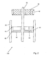
- the Figures 2 and 3 should clarify the use of the two-part piston system 40.
- the mixing cylinder 20 of the device 10 is filled with bone cement powder by the manufacturer.
- the gas-permeable sterilization piston 41 is inserted into the mixing cylinder 20.
- the resulting sterilization position 150 is in FIG. 2 shown.
- the sealing piston 42 is not inserted into the mixing cylinder 20 in the sterilization position 150, but rather is displaced on the actuating rod 50 in the direction of the handle 52.
- the manufacturer may sterilize the bone cement, the device 10, and the bone cement system 100 with a fluid.
- ethylene oxide is used for the sterilization.
- the ethylene oxide can flow through the gas-permeable sterilization flask into the mixing cylinder and flush out the bone cement powder.
- the sterilization piston 41 has a screen-like structure 66. This sieve-like structure 66 allows the sterilization gas to flow into the mixing cylinder 20.
- the sieve-like structure 66 allows only an inflow of particles smaller than 5 ⁇ m. This prevents impurities from flowing into the bone cement powder.
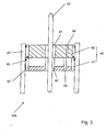
- the device 10 is transferred from the sterilization position 150 into a mixing position 155, which in FIG. 3 is shown.
- the sealing piston 42 can be plugged onto the sterilization piston.
- both pistons 41, 42 may have corresponding means in order to achieve a non-positive and / or positive connection.
- the device 10 is connected to a vacuum system.
- the piston system 40 has a vacuum connection 68. This vacuum connection 68 is arranged in the sealing piston 42. Since the sterilization piston 41 is permeable to gas, this requires no vacuum connection.
- the vacuum port 68 is used to achieve a negative pressure in the interior of the mixing cylinder 20.
- part of the bone cement system is also the storage element 110.
- the storage element 110 stores a reservoir 112 for the monomer. Via a valve means 115, an outflow of the monomer from the reservoir 112 can be controlled and / or triggered.
- the storage container 112 is a glass container which is opened in the head region by the valve means 115.
- the monomer then flows through a conduit 122 from the reservoir 112 into the mixing cylinder 20.
- the overflow of the monomer is enhanced by the fact that in the mixing cylinder 20, there is a negative pressure.
- the device 10 may be unscrewed from the base member 120.
- the base element 120 has a coupling means 121, which cooperates with a connection means 22 of the mixing piston.
- the actuating rod 50 is axially displaced so that the mixing piston 21 comes to rest on the piston system 40. Subsequently, the actuating rod can be bent at the predetermined breaking point 51.
- the device 10 can now be integrated into a cementing gun. By actuating the cementing gun, a rack with a plate is moved in the direction of the piston system 40.
- the piston system 40 is not only to be used for the sterilization and mixing of the bone cement, but can also be used for discharging the bone cement.
- the piston system 40 is designed to be axially movable.
- the piston system 40 can be axially engaged in the mixing cylinder 20. It is thus achieved that the bone cement mixed with bone cement powder and the monomer can be discharged through a discharge opening 23.
- Both the sterilization piston 41 and the sealing piston 42 of the piston system 40 according to the invention have sealing means 65. These prevent environmental influences from flowing into the interior of the mixing cylinder. Moreover, the two pistons 41, 42 of the piston system 40 have guide means 67, which serve to support the actuating rod 50. Thus, a tilting of the two pistons 41,42 is prevented. So that the sterilization piston 41 does not have to be removed from the mixing cylinder 20 when filling the device 10 with the bone cement powder, the sterilization piston 41 can have a filling opening 69. By means of this in particular reversibly closable filling opening, the bone cement powder can be filled into the interior of the mixing cylinder 20.
Abstract
Description
Die Erfindung betrifft eine Vorrichtung zum Mischen und Austragen von Knochenzement gemäß den Merkmalen des Oberbegriffs des Anspruchs 1, mit einem Mischzylinder, in welchem ein Mischkolben angeordnet ist, wobei der Mischkolben mittels einer an einem ersten Zylinderende gedichtet herausgeführten Betätigungsstange axial bewegbar ist. Weiterhin betrifft die Erfindung ein Knochenzementsystem mit den Merkmalen des Patentanspruchs 11.The invention relates to a device for mixing and discharging bone cement according to the features of the preamble of claim 1, with a mixing cylinder, in which a mixing piston is arranged, wherein the mixing piston is axially movable by means of a seal rod led out sealed at a first cylinder end. Furthermore, the invention relates to a bone cement system with the features of claim 11.
Polymethylmethacrylat-(PMMA)-Knochenzemente gehen auf die grundlegenden Arbeiten von Sir Charnley zurück (
Eine Weiterentwicklung stellen Zementiersysteme dar, in denen sowohl das Zementpulver als auch die Monomerflüssigkeit bereits in separaten Kompartimenten der Mischsysteme verpackt sind und erst unmittelbar vor der Zementapplikation im Zementiersystem miteinander vermischt werden (
Bei auf dem Markt befindlichen Mischsystemen wird dieser Widerspruch dadurch gelöst, dass auf der Zementkartusche ein Deckel mit einer porösen Scheibe aufgeschraubt ist, der unmittelbar vor der Zementapplikation entfernt werden muss. Anstelle dieses Deckels wird ein vakuumdichter Kartuschenkopf aufgeschraubt, der eine Mischvorrichtung, einen Vakuumanschluss und eine Öffnung für das später aufzusetzende Austragsrohr enthält. Der medizinische Anwender muss daher das Zementiersystem unmittelbar vor der Zementanmischung öffnen und dann wieder verschließen. Dadurch können Keime etc. an das zuvor desinfizierte Knochenzementpulver gelangen.In the case of mixing systems on the market, this contradiction is solved by that on the cement cartridge a cover with a porous disc is screwed, which must be removed immediately before the cement application. Instead of this cover, a vacuum-tight cartridge head is screwed, which contains a mixing device, a vacuum connection and an opening for the later aufzusetzende discharge pipe. The medical user must therefore open the cementing system immediately before the cement mixture and then close it again. As a result, germs etc. can get to the previously disinfected bone cement powder.
Es ist die Aufgabe der vorliegenden Erfindung, eine Vorrichtung zum Mischen und Austragen von Knochenzement zu schaffen, bei der die genannten Nachteile vermieden werden, insbesondere eine Verunreinigung des desinfizierten Knochenzementpulvers verhindert wird.It is the object of the present invention to provide a device for mixing and discharging bone cement, in which the mentioned disadvantages are avoided, in particular contamination of the disinfected bone cement powder is prevented.
Zur Lösung dieser Aufgabe wird eine Vorrichtung zum Mischen und Austragen von Knochenzement mit den Merkmalen des Anspruchs 1 vorgeschlagen. Weiterhin wird zur Lösung dieser Aufgabe ein Knochenzementsystem mit den Merkmalen des Anspruchs 10 vorgeschlagen. In den abhängigen Ansprüchen sind jeweils bevorzugte Weiterbildungen ausgeführt. Merkmale und Details, die in Zusammenhang mit der Vorrichtung offenbart werden, gelten dabei selbstverständlich auch für das erfindungsgemäße Knochenzementsystem und umgekehrt.To solve this problem, a device for mixing and discharging bone cement with the features of claim 1 is proposed. Furthermore, a bone cement system with the features of
Für die erfindungsgemäße Vorrichtung ist vorgesehen, dass im Bereich des ersten Zylinderendes ein axial bewegbares zweiteiliges Kolbensystem angeordnet ist, wobei das Kolbensystem einen Sterilisationskolben und einen Dichtungskolben aufweist, der Sterilisationskolben und der Dichtungskolben getrennt axial auf der Betätigungsstange bewegbar sind, der Sterilisationskolben den Mischzylinder gasdurchlässig abschließt und der Dichtungskolben den Mischzylinder gasdicht abschließt.For the device according to the invention, it is provided that an axially movable two-part piston system is arranged in the region of the first cylinder end, wherein the piston system has a sterilization piston and a sealing piston, the sterilization piston and the sealing piston are axially movable separately on the actuating rod, the sterilization piston closes the mixing cylinder gas-permeable and the sealing piston seals the mixing cylinder gas-tight.
Der Sterilisationskolben ist zwischen dem Mischkolben und dem Dichtungskolben auf der Betätigungsstange angeordnet. Durch diese Anordnung der zwei Teile des Kolbensystems ist sichergestellt, dass ein Sterilisationsmittel in den Mischzylinder einströmen kann, ohne von dem Dichtungskolben daran gehindert zu werden. Erst im Anschluss wird der Dichtungskolben auf den Sterilisationskolben aufgebracht und somit das zweiteilige Kolbensystem kombiniert.The sterilization piston is arranged between the mixing piston and the sealing piston on the actuating rod. This arrangement of the two parts of the piston system ensures that a sterilizing agent can flow into the mixing cylinder without being hindered by the sealing piston. Only then is the sealing piston applied to the sterilization piston, thus combining the two-part piston system.
Der Kern der hier beschriebenen Erfindung besteht darin, ein Ende des Mischzylinders mit einem zweiteiligen Kolbensystem zu verschließen. Die zwei Teile des Kolbensystems können unabhängig voneinander auf der Betätigungsstange axial verschoben werden. Der Sterilisationskolben verschließt den Mischzylinder gasdurchlässig. Somit kann ein Sterilisationsmittel in den Mischzylinder einströmen und das dort gelagerte Knochenzementpulver sterilisieren. Der Dichtungskolben des Kolbensystems ermöglicht dann einen gasdichten Abschluss des Mischzylinders, um diesen mit einem Vakuum zu verbinden und einen Binder für das Knochenzementpulver in den Mischkolben einzusaugen. Vorzugsweise zeichnet sich das zweiteilige Kolbensystem dadurch aus, dass der Sterilisationskolben den Mischzylinder gasdurchlässig abschließt, um ein Durchspülen eines Knochenzementpulvers mit einem Sterilisationsmittels zu ermöglichen und der Dichtungskolben den Mischzylinder gasdicht abschließt, um ein Durchspülen des Knochenzementpulvers mit einem Binder, insbesondere einem Monomer zu ermöglichen.The essence of the invention described herein is to close one end of the mixing cylinder with a two-part piston system. The two parts of the piston system can be moved axially independently on the actuating rod. The sterilization piston closes the mixing cylinder in a gas-permeable manner. Thus, a sterilizing agent can flow into the mixing cylinder and sterilize the bone cement powder stored there. The sealing piston of the piston system then allows a gas-tight completion of the mixing cylinder to connect it with a vacuum and to suck a binder for the bone cement powder in the mixing flask. Preferably, the two-part piston system is characterized in that the sterilization piston gas-permeable completion of the mixing cylinder to allow flushing a bone cement powder with a sterilizing agent and the sealing piston the mixing cylinder gas-tight, to allow flushing of the bone cement powder with a binder, in particular a monomer.
Die Besonderheit besteht darin, dass einerseits eine möglichst große gaspermeable Fläche im Zementmischsystem vorhanden ist, damit Ethylenoxid zur Sterilisation einströmen kann und nach erfolgter Sterilisation wieder ausgasen kann und dass andererseits ein vakuumdichter Verschluss vorhanden ist, damit ein Vakuum-Anmischen des Knochenzements in der verschlossenen Kartusche möglich ist. Das Kolbensystem kann gleichzeitig als Kolben zum Austragen des gemischten Zements aus der Kartusche verwendet werden. Das zweiteilige Kolbensystem erfüllt somit insgesamt drei Vorteile: Zum ersten ist es möglich, durch eine Abdichtung des Mischzylinders durch den Sterilisationskolben das Knochenzementpulver mit einem gasförmigen Fluid zu desinfizieren. Im Anschluss wird der Dichtungskolben genutzt, um den Sterilisationskolben abzudichten. Dadurch ist ein Mischen des Knochenzementpulvers mit einem Binder, insbesondere einem Monomer, unter Vakuum möglich. Anschließend wird das aus Dichtungskolben und Sterilisationskolben gebildete Kolbensystem genutzt, um in den Mischzylinder eingeschoben zu werden und dadurch den Knochenzement aus diesem auszupressen.The special feature is that on the one hand the largest possible gas-permeable surface in the cement mixing system is present so that ethylene oxide can flow into the sterilization and outgas again after sterilization and that on the other hand, a vacuum-tight closure is present, thus a vacuum mixing of the bone cement in the sealed cartridge is possible. The piston system can be used simultaneously as a piston for discharging the mixed cement from the cartridge. The two-part piston system thus fulfills a total of three advantages: First, it is possible to disinfect the bone cement powder with a gaseous fluid by sealing the mixing cylinder by the sterilization piston. Subsequently, the sealing piston is used to seal the sterilization flask. This makes it possible to mix the bone cement powder with a binder, in particular a monomer, under vacuum. Subsequently, the piston system formed from sealing piston and sterilization piston is used to be inserted into the mixing cylinder and thereby squeeze the bone cement out of this.
Im Rahmen der Erfindung soll der Dichtungskolben den Mischzylinder gasdicht abschließen. Damit soll verdeutlicht werden, dass der Dichtungskolben den Mischzylinder gegenüber den beim Mischen auftretenden und dem Fachmann bekannten Drücken abschließt. Das in den Mischzylinder mittels einer Vakuumpumpe eingebrachte Vakuum soll nicht wesentlich durch etwaige Leckage des Dichtungskolbens gegenüber dem Mischzylinder geschwächt werden. Im Rahmen der Erfindung soll der Begriff "gasdurchlässig" verdeutlichen, dass ein gasförmiges Sterilisationsfluid durch den Sterilisationskolben in den Mischzylinder einströmen kann. Vorzugsweise weist der Sterilisationskolben ein gasdurchlässiges Gitter auf, das Partikel, die kleiner als 5 µm sind, durchlässt. Größere Partikel sollten von dem gasdurchlässigen Sterilisationskolben nicht in das Innere des Mischzylinders gelassen werden.In the context of the invention, the sealing piston is intended to seal off the mixing cylinder in a gastight manner. This is intended to make it clear that the sealing piston closes the mixing cylinder with respect to the pressures occurring during mixing and known to those skilled in the art. The introduced into the mixing cylinder by means of a vacuum pump vacuum should not be significantly weakened by any leakage of the sealing piston relative to the mixing cylinder. In the context of the invention, the term "gas-permeable" to illustrate that a gaseous Sterilization fluid can flow through the sterilization flask in the mixing cylinder. Preferably, the sterilization flask has a gas-permeable screen which allows particles smaller than 5 μm to pass. Larger particles should not be allowed to enter the mixing cylinder from the gas permeable sterilization flask.
Eine vorteilhafte Ausführungsvariante der erfindungsgemäßen Vorrichtung zeichnet sich dadurch aus, dass das zweiteilige Kolbensystem die Betätigungsstange umschließt. Dabei hat es sich als besonders vorteilhaft herausgestellt, wenn das Kolbensystem und/oder der Sterilisationskolben und/oder der Dichtungskolben zylinderartig ausgestaltet sind. Durch die Anordnung des Kolbensystems um die Betätigungsstange ist ein einfaches und reversibles Verschieben des Dichtungskolbens auf den Sterilisationskolben zu bzw. von diesem weg möglich. In einer Sterilisationsstellung ist der Sterilisationskolben in dem Mischzylinder angeordnet, während der Dichtungskolben beispielsweise außerhalb des Mischzylinders, aber auf der Betätigungsstange angeordnet ist. So ist sichergestellt, dass ein Sterilisationsmittel ungehindert in das Innere des Mischzylinders einströmen kann. In einer Mischsituation wird dann der Dichtungskolben auf den Sterilisationskolben aufgebracht, so dass das Kolbensystem zusammen angeordnet ist. Durch den Dichtungskolben wird verhindert, dass das im Inneren des Mischzylinders herrschende Vakuum geschwächt werden kann.An advantageous embodiment of the device according to the invention is characterized in that the two-part piston system encloses the actuating rod. It has been found to be particularly advantageous if the piston system and / or the sterilization piston and / or the sealing piston are designed like a cylinder. The arrangement of the piston system to the actuating rod is a simple and reversible displacement of the sealing piston on the sterilizing piston to or away from this possible. In a sterilization position, the sterilization piston is arranged in the mixing cylinder, while the sealing piston is arranged outside the mixing cylinder, for example, but on the actuating rod. This ensures that a sterilizing agent can flow unhindered into the interior of the mixing cylinder. In a mixed situation, the sealing piston is then applied to the sterilization piston, so that the piston system is arranged together. The sealing piston prevents the vacuum prevailing inside the mixing cylinder from being weakened.
Um eine kraft- und/oder formschlüssige Verbindung zwischen dem Dichtungskolben und dem Sterilisationskolben herzustellen, hat es sich als bevorzugt herausgestellt, wenn der Dichtungskolben auf den Sterilisationskolben aufsteckbar ist. Beide Kolben des Kolbensystems können über entsprechende Clipverbindungen verfugen, so dass der Sterilisationskolben auf den Dichtungskolben aufsteckbar ist. Diese Clipverbindung kann reversibel lösbar ausgestaltet sein, um ein mehrfaches Aufbringen des Sterilisationskolbens zu ermöglichen.In order to produce a non-positive and / or positive connection between the sealing piston and the sterilizing piston, it has proven to be preferred when the sealing piston can be plugged onto the sterilizing piston. Both pistons of the piston system can grout via corresponding clip connections, so that the sterilization piston can be plugged onto the sealing piston. This clip connection can be made reversibly detachable to allow multiple application of the sterilization flask.
Eine Besonderheit der erfindungsgemäßen Vorrichtung besteht darin, dass durch die Aufteilung des Kolbensystems in einen Dichtungskolben und einen Sterilisationskolben nicht nur das Knochenzementpulver problemlos und ohne die Gefahr einer Verunreinigung desinfiziert werden kann, sondern auch ein Austragen des fertigen Knochenzements mit dem zweiteiligen Kolbensystem möglich ist. So hat es sich als vorteilhaft erwiesen, wenn das Kolbensystem axial in den Mischzylinder eindrückbar ist, um einen aus dem Knochenzementpulver und dem Binder, insbesondere dem Monomer, gemischten Knochenzement, durch eine Austragsöffnung auszutragen. Die Austragsöffnung liegt an einem zweiten Zylinderende des Mischzylinders. Das zweite Zylinderende ist dem ersten Zylinderende entgegengesetzt. Beim Austragen wird das Kolbensystem aus Richtung des ersten Zylinderendes in Richtung des zweiten Zylinderendes gedrückt und presst dabei den fertig gemischten Knochenzement durch die Austragsöffnung heraus. In einer vorteilhaften Ausgestaltung weist die Austragsöffnung ein Anschlussmittel, insbesondere ein Anschlussgewinde, auf. Dieses Anschlussgewinde kann genutzt werden, urn den Mischzylinder in das noch zu beschreibende Knochenzementsystem einzuschrauben und/oder den Mischzylinder an ein Schlauchsystem anzuschließen, über das der fertige Knochenzement in den Knochen eingebracht werden kann. Für diese Tätigkeit kann eine Auspresspistole genutzt werden, in die der Mischzylinder eingespannt wird. Zur einfachen Benutzung der Auspresspistole kann die Betätigungsstange eine Sollbruchstelle aufweisen, so dass ein Abbrechen der Betätigungsstange an einer definierten Stelle möglich ist. Zum Austragen des fertig gemischten Knochenzements wird die Betätigungsstange in Richtung des Kolbensystems gezogen, bis der Mischkolben an dem Kolbensystem anliegt. Durch das dann erfolgende Abtrennen der Betätigungsstange kann das Kolbensystem mit dem davor anliegenden Mischkolben in den Mischzylinder eingepresst werden.A special feature of the device according to the invention is that by dividing the piston system into a sealing piston and a sterilization piston not only the bone cement powder can be disinfected without problems and without the risk of contamination, but also a discharge of the finished bone cement with the two-part piston system is possible. Thus, it has proved to be advantageous if the piston system can be pressed axially into the mixing cylinder in order to discharge a bone cement mixed from the bone cement powder and the binder, in particular the monomer, through a discharge opening. The discharge opening is located at a second cylinder end of the mixing cylinder. The second cylinder end is opposite to the first cylinder end. At the When discharging, the piston system is pressed from the direction of the first cylinder end in the direction of the second cylinder end, thereby forcing the ready mixed bone cement out through the discharge opening. In an advantageous embodiment, the discharge opening has a connection means, in particular a connection thread. This connection thread can be used to screw the mixing cylinder into the bone cement system to be described later and / or to connect the mixing cylinder to a tube system via which the finished bone cement can be introduced into the bone. For this activity, an extrusion gun can be used, in which the mixing cylinder is clamped. For easy use of the Auspresspistole the actuating rod may have a predetermined breaking point, so that a cancel of the actuating rod at a defined location is possible. To discharge the ready-mixed bone cement, the actuating rod is pulled in the direction of the piston system until the mixing piston rests against the piston system. By then taking place separating the actuating rod, the piston system can be pressed with the mixing piston in front of it in the mixing cylinder.
Um das Knochenzementpulver in das Innere des Mischzylinders einzufüllen, hat es sich als vorteilhaft erwiesen, wenn der Sterilisationskolben eine verschließbare, insbesondere reversibel verschließbare Öffnung aufweist. Mittels dieser Befüllöffnung ist ein leichtes Einbringen des Knochenzementpulvers in den Mischzylinder möglich, ohne dass das Kolbensystem aus dem Mischzylinder entnommen werden muss. Dadurch wird eine Reduktion des Aufwandes zum Befallen der erfindungsgemäßen Vorrichtung erreicht.To fill the bone cement powder in the interior of the mixing cylinder, it has proved to be advantageous if the sterilization piston has a closable, in particular reversibly closable opening. By means of this filling opening, it is possible to easily introduce the bone cement powder into the mixing cylinder without the piston system having to be removed from the mixing cylinder. As a result, a reduction of the effort for infilling the device according to the invention is achieved.
Weiterhin hat es sich als vorteilhaft herausgestellt, wenn der Sterilisationskolben und/oder der Dichtungskolben wenigstens ein Führungsmittel aufweist, welches zur Abstützung gegenüber der Betätigungsstange dient. Durch das Führungsmittel wird verhindert, dass einer der genannten Kolben des Kolbensystems sich in dem Mischzylinder verkantet. Diese Verkantung könnte insbesondere dann auftreten, wenn der Dichtungskolben entlang der Betätigungsstange gefahren wird, um auf dem Sterilisationskolben aufgebracht zu werden. Weiterhin ist es vorteilhaft, wenn das Kolbensystem und/oder der Sterilisationskolben und/oder der Dichtungskolben wenigstens ein Abdichtungsmittel aufweisen, um eine Abdichtung gegenüber dem Mischzylinder zu erzielen. Der Dichtungskolben soll eine gasdichte Abdichtung des Mischzylinders erzielen. Zusätzlich ist geplant, dass der Sterilisationskolben nur Partikel kleiner als 5 µm in den Mischzylinder einströmen lässt. Um diese Anforderung zu erfüllen, hat es sich als vorteilhaft erwiesen, wenn ein Abdichtungsmittel auf einer Außenfläche, die in Kontakt mit dem Mischzylinder steht, über ein Abdichtungsmittel verfügt. Dieses Abdichtungsmittel kann beispielsweise eine Gummidichtung sein, die verhindert, dass Umgebungsluft in das Innere des mit einem Vakuum versehenen Mischzylinders einströmt.Furthermore, it has been found to be advantageous if the sterilization piston and / or the sealing piston has at least one guide means which serves to support against the actuating rod. By the guide means prevents one of said piston of the piston system is tilted in the mixing cylinder. This canting could occur in particular when the sealing piston is moved along the actuating rod in order to be applied to the sterilization piston. Furthermore, it is advantageous if the piston system and / or the sterilization piston and / or the sealing piston have at least one sealing means in order to achieve a seal with respect to the mixing cylinder. The sealing piston should achieve a gas-tight seal of the mixing cylinder. In addition, it is planned that the sterilization flask will only allow particles smaller than 5 μm to flow into the mixing cylinder. To meet this requirement, it has proven to be advantageous if a sealing means on an outer surface, the in Contact with the mixing cylinder is available, has a sealant. For example, this sealing means may be a rubber seal which prevents ambient air from entering the interior of the vacuum-provided mixing cylinder.
Eine weitere vorteilhafte Ausgestaltung der erfindungsgemäßen Vorrichtung zeichnet sich dadurch aus, dass das Kolbensystem und/oder der Sterilisationskolben und/oder der Dichtungskolben wenigstens einen Vakuumanschluss aufweist. Über diesen Vakuumanschluss kann die Vorrichtung mit einer Vakuumpumpe verbunden werden. Die Vakuumpumpe erzeugt dann jenen Unterdruck, der in dem Mischzylinder vorherrschen soll. Wie später noch ausführlich beschrieben wird, sorgt der Unterdruck für ein Einfließen des Binders, insbesondere des Monomers, in das Knochenzementpulver. Die Anordnung des Vakuumanschlusses in dem Kolbensystem hat sich aufgrund der leichten Erreichbarkeit als besonders vorteilhaft herausgestellt.A further advantageous embodiment of the device according to the invention is characterized in that the piston system and / or the sterilization piston and / or the sealing piston has at least one vacuum connection. Via this vacuum connection, the device can be connected to a vacuum pump. The vacuum pump then generates the negative pressure which is to prevail in the mixing cylinder. As will be described in detail later, the negative pressure ensures that the binder, in particular the monomer, flows into the bone cement powder. The arrangement of the vacuum connection in the piston system has been found to be particularly advantageous due to the easy accessibility.
Die oben genannte Aufgabe wird ebenfalls gelöst durch ein Knochenzementsystem mit einer Vorrichtung zum Mischen und Austragen von Knochenzement, einem Vorratselement für einen Binder, insbesondere einem Monomer und einem Basiselement, wobei das Basiselement die Vorrichtung und das Vorratselement lagert, die Vorrichtung einen Mischzylinder aufweist, in welchem ein Mischkolben angeordnet ist, wobei der Mischkolben mittels einer an einem ersten Zylinderende gedichtet herausgeführten Betätigungsstange axial bewegbar ist, im Bereich des ersten Zylinderendes ein axial bewegbares zweiteiliges Kolbensystem angeordnet ist, wobei das Kolbensystem einen Sterilisationskolben und ein Dichtungskolben aufweist, ein Sterilisationskolben und der Dichtungskolben getrennt axial auf der Betätigungsstange bewegbar sind, der Sterilisationskolben den Mischzylinder gasdurchlässig abschließt und der Dichtungskolben den Mischzylinder gasdicht abschließt. Merkmale und Details, die dabei in Zusammenhang mit der Vorrichtung beschrieben wurden, gelten auch im Zusammenhang mit dem Knochenzementsystem und umgekehrt, denn das Knochenzementsystem beinhaltet die erfindungsgemäße Vorrichtung mit dem erfindungsgemäß zweiteilig ausgelegten Kolbensystem. Dabei zeichnet sich das Kolbensystem derart aus, dass der Sterilisationskolben den Mischzylinder gasdurchlässig abschließt, um ein Durchspülen eines Knochenzementpulvers mit einem Sterilisationsmittels zu ermöglichen und der Dichtungskolben den Mischzylinder gasdicht abschließt, um ein Durchspülen des Knochenzementpulvers mit einem Binder, insbesondere einem Monomer, zu ermöglichen.The above object is also achieved by a bone cement system having a device for mixing and dispensing bone cement, a reservoir element for a binder, in particular a monomer and a base element, wherein the base element supports the device and the storage element, the device has a mixing cylinder in which a mixing piston is arranged, wherein the mixing piston is axially movable by means of a sealing rod led out sealed at a first cylinder end, an axially movable two-part piston system is arranged in the region of the first cylinder end, the piston system comprising a sterilizing piston and a sealing piston, a sterilizing piston and the sealing piston are axially movable on the actuating rod, the sterilization piston gas-permeable completion of the mixing cylinder and the sealing piston seals the mixing cylinder gas-tight. Features and details, which have been described in connection with the device, also apply in connection with the bone cement system and vice versa, because the bone cement system includes the device according to the invention with the piston system according to the invention designed in two parts. In this case, the piston system is characterized in that the sterilization piston gas-permeable the mixing cylinder to allow flushing a bone cement powder with a sterilizing agent and the sealing piston the mixing cylinder gas-tight, to allow flushing of the bone cement powder with a binder, in particular a monomer.
Eine vorteilhafte Ausgestaltung des erfindungsgemäßen Knochenzementsystems zeichnet sich dadurch aus, dass das Basiselement ein Koppelmittel aufweist für eine kraft- und/oder formschlüssige Verbindung mit der Vorrichtung, insbesondere einer Austragsöffnung der Vorrichtung. Das Basiselement dient als Lager sowohl für die erfindungsgemäße Vorrichtung, als auch das Vorratselement für den Binder. Als eine Art Fundament des Knochenzementsystems können die erfindungsgemäße Vorrichtung und das Vorratselement an und/oder auf dem Basiselement angeordnet sein. Da die erfindungsgemäße Vorrichtung auch zum Austragen des Knochenzements genutzt werden soll, ist es vorteilhaft, wenn die Vorrichtung reversibel von dem Basiselement trennbar ist. Dies kann durch das erfindungsgemäße Koppelement erreicht werden. Vorteilhafterweise handelt es sich bei dem Koppelelement um ein Gewinde, auf welches die Austragsöffnung der Vorrichtung aufgeschraubt werden kann. So ist eine sichere Verbindung zwischen dem Basiselement und der Vorrichtung gewährleistet.An advantageous embodiment of the bone cement system according to the invention is characterized in that the base element has a coupling means for a non-positive and / or positive connection with the device, in particular a discharge opening of the device. The base element serves as a bearing for both the device according to the invention and the storage element for the binder. As a kind of foundation of the bone cement system, the device according to the invention and the storage element can be arranged on and / or on the base element. Since the device according to the invention should also be used for discharging the bone cement, it is advantageous if the device is reversibly separable from the base element. This can be achieved by the coupling element according to the invention. Advantageously, the coupling element is a thread onto which the discharge opening of the device can be screwed. This ensures a secure connection between the base element and the device.
Weiterhin ist es vorteilhaft, wenn das Vorratselement einen Vorratsbehälter für den Binder, insbesondere den Monomer, lagert. Zur Herstellung des Knochenzements muss der Binder, insbesondere der Monomer, in das Knochenzementpulver eingebracht werden. Nach einer gewissen Zeitspanne härtet der Knochenzement dann aus. Offensichtlich kann der Knochenzement somit nicht austragsfertig in der Vorrichtung ausgeliefert werden. Es ist somit notwendig, dass das Knochenzementpulver und der Binder, insbesondere der Monomer, bis kurz vor dem Austragen des Knochenzements getrennt gelagert werden müssen. Somit bietet es sich an, wenn das Vorratselement einen Vorratsbehälter für den Binder, insbesondere den Monomer, aufweist. Als leicht zu desinfizieren haben sich insbesondere Glasbehälter herausgestellt, die als Vorratsbehälter für den Binder, insbesondere den Monomer, genutzt werden. Um einen Zufluss des Monomers zu steuern, kann das Vorratselement ein Ventilmittel aufweisen. Dieses Ventilmittel steuert und/oder löst den Zufluss des Monomers aus dem Vorratsbehälter in die erfindungsgemäße Vorrichtung aus.Furthermore, it is advantageous if the storage element stores a storage container for the binder, in particular the monomer. To prepare the bone cement, the binder, in particular the monomer, must be introduced into the bone cement powder. After a certain period of time, the bone cement then hardens. Obviously, the bone cement can thus not be delivered ready for delivery in the device. It is thus necessary that the bone cement powder and the binder, in particular the monomer, have to be stored separately until just before the bone cement is discharged. Thus, it makes sense if the storage element has a reservoir for the binder, in particular the monomer. As easy to disinfect glass containers have been found that are used as a reservoir for the binder, especially the monomer. In order to control an inflow of the monomer, the storage element may comprise a valve means. This valve means controls and / or triggers the inflow of the monomer from the reservoir into the device according to the invention.
Damit der Binder, insbesondere der Monomer, aus dem Vorratselement in die Vorrichtung strömen kann, weist das Basiselement ein Leitungsmittel auf. Bei diesem Leitungsmittel kann es sich insbesondere um eine Kapillare handeln. Der Binder, insbesondere der Monomer, fließt aus dem Vorratsbehälter durch das Ventilmittel und das Leitungsmittel in die Vorrichtung, insbesondere in den Mischzylinder. Dort findet eine Vermischung des Binders, insbesondere des Monomers, mit dem Knochenzementpulver statt, um den Knochenzement zu bilden.So that the binder, in particular the monomer, can flow from the storage element into the device, the base element has a conduit means. This conduit may in particular be a capillary. The binder, in particular the monomer, flows from the reservoir through the valve means and the conduit means into the apparatus, in particular into the mixing cylinder. There, mixing of the binder, especially the monomer, with the bone cement powder takes place to form the bone cement.
Weitere Einzelheiten und Vorteile der Erfindung ergeben sich aus den Ansprüchen, der nachfolgenden Beschreibung und den Zeichnungen. In den Zeichnungen ist die Erfindung in einem Ausführungsbeispiel dargestellt. Es zeigen:
- Fig. 1
- eine schematische Schnittzeichnung eines erfindungsgemäßen Knochenzementsystems,
- Fig. 2
- ein erfindungsgemäßes Kolbensystem in einer Sterilisationsstellung und
- Fig. 3
- das erfindungsgemäße Kolbensystem in einer Mischstellung.
- Fig. 1
- a schematic sectional view of a bone cement system according to the invention,
- Fig. 2
- an inventive piston system in a sterilization position and
- Fig. 3
- the piston system according to the invention in a mixing position.
In
Die erfindungsgemäße Vorrichtung 10 zum Mischen und Austragen von Knochenzement weist einen Mischzylinder 20 auf. In dem Mischzylinder 20 ist eine Betätigungsstange 50 angeordnet, welche über einen Handgriff 52 axial bewegt werden kann. Wie dargestellt, weist die Betätigungsstange 50 an einem Ende einen Mischkolben 21 auf, der für eine Vermengung des Knochenzementpulvers und des Monomers genutzt werden kann. An einem ersten Zylinderende 30 ist ein Kolbensystem 40 angeordnet. Durch das Kolbensystem 40 wird die Betätigungsstange 50 gedichtet herausgeführt. Die Besonderheit der erfindungsgemäßen Vorrichtung 10 besteht darin, dass das Kolbensystem 40 axial beweglich ist und zweiteilig aufgebaut ist. Das Kolbensystem 40 weist einen Sterilisationskolben 41 und einen Dichtungskolben 42 auf.The
Die
Wie die
Sowohl der Sterilisationskolben 41 als auch der Dichtungskolben 42 des erfindungsgemäßen Kolbensystems 40 weisen Abdichtungsmittel 65 auf. Diese verhindern, dass Umgebungseinflüsse in das Innere des Mischzylinders einströmen können. Darüberhinaus weisen die beiden Kolben 41,42 des Kolbensystems 40 Führungsmittel 67 auf, die zur Abstützung gegenüber der Betätigungsstange 50 dienen. So wird ein Verkanten der beiden Kolben 41,42 verhindert. Damit beim Befüllen der Vorrichtung 10 mit dem Knochenzementpulver der Sterilisationskolben 41 nicht aus dem Mischzylinder 20 entnommen werden muss, kann der Sterilisationskolben 41 über eine Befüllöffnung 69 verfügen. Durch diese insbesondere reversibel verschließbare Befüllöffnung kann das Knochenzementpulver in das Innere des Mischzylinders 20 eingefüllt werden.Both the
- 1010
- Vorrichtungcontraption
- 2020
- Mischzylindermixing cylinder
- 2121
- Mischkolbenmixing piston
- 2222
- Anschlussmittelconnection means
- 2323
- Austragsöffnungdischarge
- 3030
- erstes Zylinderendefirst cylinder end
- 3535
- zweites Zylinderendesecond cylinder end
- 4040
- Kolbensystempiston system
- 4141
- Sterilisationskolbensterilization piston
- 4242
- Dichtungskolbenseal piston
- 5050
- Betätigungsstangeactuating rod
- 5151
- SollbruchstelleBreaking point
- 5252
- Handgriffhandle
- 6262
- Führungsmittelguide means
- 6565
- Abdichtungsmittelsealant
- 6666
- siebartige Struktursieve-like structure
- 6767
- Führungsmittelguide means
- 6868
- Vakuumanschlussvacuum connection
- 6969
- Befüllöffnungfilling
- 100100
- KnochenzementsystemBone cement system
- 110110
- Vorratselementstorage element
- 112112
- Vorratsbehälterreservoir
- 115115
- Ventilmittelvalve means
- 120120
- Basiselementbase element
- 121121
- Koppelmittelcoupling means
- 122122
- Leitungsmittelconduit means
- 150150
- Sterilisationsstellungsterilizing position
- 155155
- Mischstellungmixing position
Claims (14)
mit einem Mischzylinder (20), in welchem ein Mischkolben (21) angeordnet ist, wobei
der Mischkolben (21) mittels einer an einem ersten Zylinderende (30) gedichtet herausgeführten Betätigungsstange (50) axial bewegbar ist,
und mit einem im Bereich des ersten Zylinderendes (30) angeordneten und auf der Betätigungsstange (50) axial bewegbaren Dichtungskolben (42), der den Mischzylinder (20) gasdicht abschließt,
dadurch gekennzeichnet, dass
im Bereich des ersten Zylinderendes (30) zwischen dem Mischkolben (21) und dem Dichtungskolben (42) ein Sterilisationskolben (41) angeordnet ist,
der getrennt von dem Dichtungskolben (42) auf der Betätigungsstange (50) axial bewegbar ist, und den Mischzylinder (20) gasdurchlässig abschließt, wobei
der Sterilisationskolben (41) mit dem Dichtungskolben (42) ein zweiteiliges Kolbensystem (40) bildet.Device (10) for mixing and dispensing bone cement,
with a mixing cylinder (20) in which a mixing piston (21) is arranged, wherein
the mixing piston (21) is axially movable by means of an actuating rod (50) guided out in sealed manner at a first cylinder end (30),
and with a sealing piston (42) arranged in the region of the first cylinder end (30) and axially movable on the actuating rod (50), which seals off the mixing cylinder (20) in a gastight manner,
characterized in that
a sterilization piston (41) is arranged in the region of the first cylinder end (30) between the mixing piston (21) and the sealing piston (42),
which is axially movable separately from the sealing piston (42) on the actuating rod (50), and the mixing cylinder (20) is gas-permeable, wherein
the sterilization piston (41) forms a two-part piston system (40) with the sealing piston (42).
dadurch gekennzeichnet, dass das Vorratselement (110) einen Vorratsbehälter (112) für den Binder, insbesondere den Monomer, lagert, insbesondere, dass der Vorratsbehälter (112) ein Glasbehälter ist.Bone cement system (100) according to one of the preceding claims 10 or 11,
characterized in that the storage element (110) supports a storage container (112) for the binder, in particular the monomer, in particular, that the storage container (112) is a glass container.
dadurch gekennzeichnet, dass das Vorratselement (110) ein Ventilmittel (115) aufweist, um einen Ausfluss des Monomers aus dem Vorratsbehälter (112) zu steuern und/oder auszulösen.Bone cement system (100) according to one of the preceding claims 10 to 12,
characterized in that the storage element (110) comprises a valve means (115) for controlling and / or triggering an outflow of the monomer from the storage container (112).
dadurch gekennzeichnet, dass das Basiselement ein Leitungsmittel (122) aufweist, wobei durch das Leitungsmittel (122) der Monomer aus dem Vorratsbehälter (112) in die Vorrichtung (10), insbesondere den Mischzylinder (20), strömt.Bone cement system (100) according to one of the preceding claims 10 to 13,
characterized in that the base member comprises a conduit means (122), wherein through the conduit means (122) the monomer from the reservoir (112) into the device (10), in particular the mixing cylinder (20) flows.
Applications Claiming Priority (1)
| Application Number | Priority Date | Filing Date | Title |
|---|---|---|---|
| DE102009031178A DE102009031178B3 (en) | 2009-06-29 | 2009-06-29 | Device for mixing and delivering bone cement |
Publications (3)
| Publication Number | Publication Date |
|---|---|
| EP2269718A2 true EP2269718A2 (en) | 2011-01-05 |
| EP2269718A3 EP2269718A3 (en) | 2011-04-27 |
| EP2269718B1 EP2269718B1 (en) | 2013-07-31 |
Family
ID=42558186
Family Applications (1)
| Application Number | Title | Priority Date | Filing Date |
|---|---|---|---|
| EP10005897.3A Active EP2269718B1 (en) | 2009-06-29 | 2010-06-08 | Device for mixing and applying bone cement, and bone cement system |
Country Status (10)
| Country | Link |
|---|---|
| US (1) | US8757866B2 (en) |
| EP (1) | EP2269718B1 (en) |
| JP (1) | JP5634766B2 (en) |
| AU (1) | AU2010202244B2 (en) |
| CA (1) | CA2708462C (en) |
| DE (1) | DE102009031178B3 (en) |
| DK (1) | DK2269718T3 (en) |
| ES (1) | ES2432491T3 (en) |
| PT (1) | PT2269718E (en) |
| ZA (1) | ZA201004545B (en) |
Cited By (3)
| Publication number | Priority date | Publication date | Assignee | Title |
|---|---|---|---|---|
| EP2589821A1 (en) * | 2011-11-03 | 2013-05-08 | Heraeus Medical GmbH | Apparatus and method for the generation of vacuum for vacuum cementing systems |
| CN103127863A (en) * | 2011-11-25 | 2013-06-05 | 赫罗伊斯医疗有限责任公司 | Device for mixing bone cement and method for mixing bone cement and use of the device |
| EP3141267A1 (en) * | 2015-09-10 | 2017-03-15 | Heraeus Medical GmbH | Polymethylmethacrylate bone cement with adjustable initial viscosity and a method for producing a bone cement paste with variable initial viscosity |
Families Citing this family (60)
| Publication number | Priority date | Publication date | Assignee | Title |
|---|---|---|---|---|
| DE102010026497B4 (en) * | 2010-07-07 | 2014-04-03 | Heraeus Medical Gmbh | Vakuumzementiersystem |
| DE102010046055B4 (en) | 2010-09-22 | 2012-10-25 | Heraeus Medical Gmbh | Mixing device for Prepack vacuum cementing system |
| DE102010052323A1 (en) | 2010-11-25 | 2012-05-31 | Heraeus Medical Gmbh | Cartridge with lockable delivery piston |
| DE102011101486A1 (en) | 2011-05-13 | 2012-11-15 | Heraeus Medical Gmbh | Device and method for degassing and discharging bone cement |
| DE102011119377B3 (en) | 2011-11-25 | 2013-04-04 | Heraeus Medical Gmbh | Storage and mixing device for bone cement |
| US20130269826A1 (en) * | 2012-04-13 | 2013-10-17 | Kyphon Sarl | Bone Cement Component Injection System With Reduced Fume Exposure And Method |
| DE102012024710A1 (en) | 2012-11-07 | 2014-05-08 | Heraeus Medical Gmbh | Device for mixing and discharging a pasty mass |
| US9480955B2 (en) * | 2013-01-07 | 2016-11-01 | Kyphon Sarl | Bone cement mixing and delivery system with reduced fume exposure |
| DE102014101305A1 (en) * | 2014-02-03 | 2015-08-06 | Heraeus Medical Gmbh | Device for storing and mixing bone cement |
| DE102014108569B3 (en) | 2014-06-18 | 2015-10-22 | Heraeus Medical Gmbh | Vacuum mixing system and method for mixing polymethyl methacrylate bone cement |
| DE102014109905B4 (en) | 2014-07-15 | 2017-02-09 | Heraeus Medical Gmbh | Vacuum mixing system and method for mixing polymethyl methacrylate bone cement |
| DE102014112042B4 (en) | 2014-08-22 | 2017-11-23 | Heraeus Medical Gmbh | Discharge device with elastically driven mixer |
| DE102014112043A1 (en) | 2014-08-22 | 2016-02-25 | Heraeus Medical Gmbh | Tensioned opening device for monomer containers |
| DE102014117224A1 (en) | 2014-11-25 | 2016-05-25 | Heraeus Medical Gmbh | Discharge device for cement cartridges with rolling clamp bodies |
| DE102015102463A1 (en) | 2015-02-20 | 2016-08-25 | Heraeus Medical Gmbh | Discharge device for cement cartridges with spring tongues |
| DE102015106899B3 (en) * | 2015-05-04 | 2016-07-14 | Heraeus Medical Gmbh | Device for mixing and storing polymethyl methacrylate bone cement |
| DE102015108783B3 (en) * | 2015-06-03 | 2016-07-14 | Heraeus Medical Gmbh | Device for mixing and storing polymethyl methacrylate bone cement |
| EP3106146A1 (en) * | 2015-06-15 | 2016-12-21 | Dentsply DeTrey GmbH | Aqueous dental glass ionomer composition |
| DE102015111320B4 (en) | 2015-07-13 | 2018-10-18 | Heraeus Medical Gmbh | Vacuum mixing system and method for mixing polymethyl methacrylate bone cement |
| DE102015116245B4 (en) | 2015-09-25 | 2019-01-31 | Heraeus Medical Gmbh | Apparatus and method for opening glass ampoules and cementing apparatus |
| DE102015116797B4 (en) | 2015-10-02 | 2018-08-23 | Heraeus Medical Gmbh | Apparatus and method for storing and mixing a bone cement |
| DE102015121277B3 (en) | 2015-12-07 | 2017-04-06 | Heraeus Medical Gmbh | Vacuum mixing device with operating element, pressure and vacuum pump for mixing polymethyl methacrylate bone cement |
| DE102015121274B3 (en) | 2015-12-07 | 2017-04-06 | Heraeus Medical Gmbh | Vacuum mixing device with operating element and pump for mixing polymethyl methacrylate bone cement |
| DE102015121276B3 (en) | 2015-12-07 | 2017-04-06 | Heraeus Medical Gmbh | Mixing device with operating element and pressure pump for mixing polymethyl methacrylate bone cement |
| DE102016106261B4 (en) | 2016-04-06 | 2018-03-15 | Heraeus Medical Gmbh | Device for mixing and storing polymethyl methacrylate bone cement with pressure pump and vial breaker |
| EP3231412A3 (en) * | 2016-04-15 | 2017-10-25 | DENTSPLY DETREY GmbH | Aqueous dental glass ionomer composition |
| DE102016110561A1 (en) | 2016-06-08 | 2017-12-14 | Heraeus Medical Gmbh | Storage and mixing device for producing a bone cement |
| DE102016110564B4 (en) | 2016-06-08 | 2018-05-09 | Heraeus Medical Gmbh | Storage and mixing device for bone cement with pressure pump |
| DE102016222158A1 (en) | 2016-11-11 | 2018-05-17 | Heraeus Medical Gmbh | A method for producing a polymethylmethacrylate bone cement, bone cement kit for use in such a method, and a bone cement producible by such a method |
| DE102016121607B4 (en) | 2016-11-11 | 2019-05-16 | Heraeus Medical Gmbh | Apparatus and method for storing and mixing a bone cement |
| DE102016121606B4 (en) | 2016-11-11 | 2019-05-02 | Heraeus Medical Gmbh | Bone cement applicator with bone cement driven closure system and method of applying a bone cement |
| EP3338757A1 (en) * | 2016-12-20 | 2018-06-27 | Dentsply DeTrey GmbH | Direct dental filling composition |
| DE102017104854B4 (en) | 2017-03-08 | 2019-05-29 | Heraeus Medical Gmbh | Two-part storage and mixing device for producing a bone cement and method for this |
| DE102017107569A1 (en) | 2017-04-07 | 2018-10-11 | Heraeus Medical Gmbh | Device for storing, mixing and discharging a bone cement and method therefor |
| DE102017109255A1 (en) | 2017-04-28 | 2018-10-31 | Heraeus Medical Gmbh | Bone cement application device with closure means on the discharge piston |
| DE102017110732B4 (en) | 2017-05-17 | 2021-01-28 | Heraeus Medical Gmbh | Apparatus for producing a bone cement dough and for discharging the mixed bone cement dough, and a method for producing a bone cement dough |
| DE102017113126A1 (en) | 2017-06-14 | 2018-12-20 | Heraeus Medical Gmbh | Bone cement applicator with duct element and lock receptacle |
| DE102017125592B4 (en) | 2017-11-02 | 2019-06-19 | Heraeus Medical Gmbh | Powder-liquid bone cement mixer with compressed gas connection |
| DE102017130084B4 (en) | 2017-12-15 | 2019-06-27 | Heraeus Medical Gmbh | Bone cement mixing device with spacer in a vial holder |
| DE102018101041A1 (en) | 2018-01-18 | 2019-07-18 | Heraeus Medical Gmbh | Bone cement applicator with sealable gassing opening |
| US10722427B2 (en) * | 2018-03-29 | 2020-07-28 | Simon Charles Cantor | Hermetically sealable case for medical device and medicine |
| DE102018209807A1 (en) | 2018-06-18 | 2019-12-19 | Heraeus Medical Gmbh | Bone cement applicator with retractable mixing stick and method for producing a bone cement |
| DE102018209784A1 (en) | 2018-06-18 | 2019-12-19 | Heraeus Medical Gmbh | Bone cement applicator with retractable mixing stick and method for producing a bone cement |
| DE102018218303A1 (en) | 2018-10-25 | 2020-04-30 | Heraeus Medical Gmbh | Device for providing bone cement |
| DE102018218302A1 (en) | 2018-10-25 | 2020-04-30 | Heraeus Medical Gmbh | Device for providing bone cement |
| EP3643398B1 (en) | 2018-10-25 | 2021-07-07 | Heraeus Medical GmbH | Device and method for producing bone cement |
| DE102018131268B4 (en) | 2018-12-07 | 2021-11-25 | Heraeus Medical Gmbh | Device for mixing a bone cement with a cavity for monomer transfer |
| DE102018131266B4 (en) | 2018-12-07 | 2021-12-23 | Heraeus Medical Gmbh | Apparatus for mixing a bone cement with a cavity for monomer transfer and a process for the production of a bone cement dough |
| DE102019104020A1 (en) | 2019-02-18 | 2020-08-20 | Heraeus Medical Gmbh | Bone cement applicator with clampable discharge piston |
| EP3838391A1 (en) | 2019-12-18 | 2021-06-23 | Heraeus Medical GmbH | Device for producing bone cement |
| EP4063007B1 (en) | 2021-03-22 | 2023-08-09 | Heraeus Medical GmbH | Method and device for mixing bone cement with pressure relief |
| EP4079396B1 (en) | 2021-04-22 | 2024-01-03 | Heraeus Medical GmbH | Device for producing bone cement |
| CN113368768B (en) * | 2021-05-24 | 2023-12-05 | 浙江弼土新材料股份有限公司 | Asphalt pavement regenerant manufacturing system |
| EP4154973B1 (en) | 2021-09-28 | 2024-01-17 | Heraeus Medical GmbH | Device for preparing bone cement paste |
| CN114272840B (en) * | 2021-12-31 | 2022-10-11 | 岳阳职业技术学院 | Solid reagent dissolving device for clinical pharmacy |
| CN114148614B (en) * | 2022-02-10 | 2022-04-29 | 莱州市文昌路畜牧兽医站 | Poultry animal doctor holds instrument with liquid medicine |
| EP4257232A1 (en) | 2022-04-04 | 2023-10-11 | Heraeus Medical GmbH | Device and method for producing bone cement |
| EP4282518A1 (en) | 2022-05-23 | 2023-11-29 | Heraeus Medical GmbH | Device and method for producing bone cement |
| EP4299169A1 (en) | 2022-06-30 | 2024-01-03 | Heraeus Medical GmbH | Device and method for producing bone cement |
| EP4309774A1 (en) | 2022-07-19 | 2024-01-24 | Heraeus Medical GmbH | Method and device for providing a bone cement mass |
Citations (12)
| Publication number | Priority date | Publication date | Assignee | Title |
|---|---|---|---|---|
| US4671263A (en) | 1984-07-11 | 1987-06-09 | Klaus Draenert | Device and process for mixing and applying bone cement |
| DE3640279A1 (en) | 1985-12-23 | 1987-06-25 | Mit Ab | DEVICE FOR MIXING BONE CEMENT IN A VACUUM |
| US4973168A (en) | 1989-01-13 | 1990-11-27 | Chan Kwan Ho | Vacuum mixing/bone cement cartridge and kit |
| US5344232A (en) | 1991-09-30 | 1994-09-06 | Stryker Corporation | Bone cement mixing and loading apparatus |
| WO1994026403A1 (en) | 1993-05-10 | 1994-11-24 | Cemvac System Ab | Method and device for feeding components for bone cement into a mixing vessel for these |
| EP0692229A1 (en) | 1994-07-16 | 1996-01-17 | MERCK PATENT GmbH | Mixing and dispensing device for bone cement |
| US5586821A (en) | 1995-10-10 | 1996-12-24 | Zimmer, Inc. | Bone cement preparation kit |
| WO1999067015A1 (en) | 1997-05-21 | 1999-12-29 | Nikomed Aps | An apparatus for preparing bone cement |
| US6033105A (en) | 1996-11-15 | 2000-03-07 | Barker; Donald | Integrated bone cement mixing and dispensing system |
| EP1005901A2 (en) | 1995-11-13 | 2000-06-07 | Cemvac System Aktiebolag | Method and device for mixing components for bone cement in a mixing vessel |
| EP1020167A2 (en) | 1999-01-14 | 2000-07-19 | Bristol-Myers Squibb Company | Apparatus and method for mixing and dispensing bone cement |
| EP1920738A2 (en) | 2004-06-22 | 2008-05-14 | Bone Support AB | Device for distributing a hardenable mass |
Family Cites Families (7)
| Publication number | Priority date | Publication date | Assignee | Title |
|---|---|---|---|---|
| US3195778A (en) * | 1963-09-17 | 1965-07-20 | Alta Engineering Company | Storage and mixing cartridge |
| WO1999020562A1 (en) * | 1997-10-20 | 1999-04-29 | Prc-Desoto International, Inc. | Multiple part manual dispensing syringe |
| JP2002532155A (en) * | 1998-12-14 | 2002-10-02 | エーオー リサーチ インスティチュート ダフォス | Preparation method of bone cement |
| US6223953B1 (en) | 1999-06-07 | 2001-05-01 | Nylok Fastener Corp. | Powder feed system |
| ATE361725T1 (en) * | 2003-12-01 | 2007-06-15 | Broockeville Corp N V | TWO-COMPONENT MIXING AND DISPENSING DEVICE |
| US20060274601A1 (en) * | 2005-06-07 | 2006-12-07 | Seaton James P Jr | Prepacked cartridge mixing system |
| SE530232C2 (en) * | 2006-08-11 | 2008-04-08 | Biomet Cementing Technologies | Liquid container for bone cement mixers |
-
2009
- 2009-06-29 DE DE102009031178A patent/DE102009031178B3/en active Active
-
2010
- 2010-05-31 AU AU2010202244A patent/AU2010202244B2/en active Active
- 2010-06-08 PT PT100058973T patent/PT2269718E/en unknown
- 2010-06-08 DK DK10005897.3T patent/DK2269718T3/en active
- 2010-06-08 EP EP10005897.3A patent/EP2269718B1/en active Active
- 2010-06-08 ES ES10005897T patent/ES2432491T3/en active Active
- 2010-06-25 CA CA2708462A patent/CA2708462C/en active Active
- 2010-06-25 JP JP2010144570A patent/JP5634766B2/en active Active
- 2010-06-28 US US12/824,310 patent/US8757866B2/en active Active
- 2010-06-28 ZA ZA2010/04545A patent/ZA201004545B/en unknown
Patent Citations (15)
| Publication number | Priority date | Publication date | Assignee | Title |
|---|---|---|---|---|
| US4671263A (en) | 1984-07-11 | 1987-06-09 | Klaus Draenert | Device and process for mixing and applying bone cement |
| DE3640279A1 (en) | 1985-12-23 | 1987-06-25 | Mit Ab | DEVICE FOR MIXING BONE CEMENT IN A VACUUM |
| US4973168A (en) | 1989-01-13 | 1990-11-27 | Chan Kwan Ho | Vacuum mixing/bone cement cartridge and kit |
| US5100241A (en) | 1989-01-13 | 1992-03-31 | Chan Kwan Ho | Vacuum mixing/bone cement cartridge and kit |
| US5344232A (en) | 1991-09-30 | 1994-09-06 | Stryker Corporation | Bone cement mixing and loading apparatus |
| WO1994026403A1 (en) | 1993-05-10 | 1994-11-24 | Cemvac System Ab | Method and device for feeding components for bone cement into a mixing vessel for these |
| EP0692229A1 (en) | 1994-07-16 | 1996-01-17 | MERCK PATENT GmbH | Mixing and dispensing device for bone cement |
| US5586821A (en) | 1995-10-10 | 1996-12-24 | Zimmer, Inc. | Bone cement preparation kit |
| US5624184A (en) | 1995-10-10 | 1997-04-29 | Chan; Kwan-Ho | Bone cement preparation kit having a breakable mixing shaft forming an output port |
| EP1005901A2 (en) | 1995-11-13 | 2000-06-07 | Cemvac System Aktiebolag | Method and device for mixing components for bone cement in a mixing vessel |
| EP1016452A2 (en) | 1995-11-13 | 2000-07-05 | Cemvac System Aktiebolag | Method and device for mixing components for bone cement in a mixing vessel |
| US6033105A (en) | 1996-11-15 | 2000-03-07 | Barker; Donald | Integrated bone cement mixing and dispensing system |
| WO1999067015A1 (en) | 1997-05-21 | 1999-12-29 | Nikomed Aps | An apparatus for preparing bone cement |
| EP1020167A2 (en) | 1999-01-14 | 2000-07-19 | Bristol-Myers Squibb Company | Apparatus and method for mixing and dispensing bone cement |
| EP1920738A2 (en) | 2004-06-22 | 2008-05-14 | Bone Support AB | Device for distributing a hardenable mass |
Non-Patent Citations (2)
| Title |
|---|
| BREUSCH SJ ET AL.: "Der Stand der Zementiertechnik in Deutschland", Z. ORTHOP., vol. 137, 1999, pages 101 - 07 |
| CHARNLEY, J.: "Anchorage of the femoral head prosthesis of the shaft of the femur", J. BONE JOINT SURG., vol. 42, 1960, pages 28 - 30 |
Cited By (5)
| Publication number | Priority date | Publication date | Assignee | Title |
|---|---|---|---|---|
| EP2589821A1 (en) * | 2011-11-03 | 2013-05-08 | Heraeus Medical GmbH | Apparatus and method for the generation of vacuum for vacuum cementing systems |
| US9470245B2 (en) | 2011-11-03 | 2016-10-18 | Heraeus Medical Gmbh | Device and method for generating vacuum for vacuum cementing systems |
| CN103127863A (en) * | 2011-11-25 | 2013-06-05 | 赫罗伊斯医疗有限责任公司 | Device for mixing bone cement and method for mixing bone cement and use of the device |
| EP3141267A1 (en) * | 2015-09-10 | 2017-03-15 | Heraeus Medical GmbH | Polymethylmethacrylate bone cement with adjustable initial viscosity and a method for producing a bone cement paste with variable initial viscosity |
| US10293078B2 (en) | 2015-09-10 | 2019-05-21 | Heraeus Medical Gmbh | Polymethylmethacrylate bone cement with adjustable initial viscosity, and method for producing a bone cement dough with variable initial viscosity |
Also Published As
| Publication number | Publication date |
|---|---|
| US20100329074A1 (en) | 2010-12-30 |
| CA2708462A1 (en) | 2010-12-29 |
| DE102009031178B3 (en) | 2010-09-16 |
| EP2269718A3 (en) | 2011-04-27 |
| CA2708462C (en) | 2016-02-16 |
| AU2010202244B2 (en) | 2014-09-18 |
| ZA201004545B (en) | 2011-04-28 |
| AU2010202244A1 (en) | 2011-01-20 |
| JP2011005255A (en) | 2011-01-13 |
| JP5634766B2 (en) | 2014-12-03 |
| US8757866B2 (en) | 2014-06-24 |
| PT2269718E (en) | 2013-10-30 |
| DK2269718T3 (en) | 2013-10-28 |
| ES2432491T3 (en) | 2013-12-03 |
| EP2269718B1 (en) | 2013-07-31 |
Similar Documents
| Publication | Publication Date | Title |
|---|---|---|
| EP2269718B1 (en) | Device for mixing and applying bone cement, and bone cement system | |
| EP3320870B1 (en) | Device and method for storing and mixing of a bone cement | |
| EP3320869B1 (en) | Bone cement applicator with closure system driven by the bone cement paste | |
| EP2730332B1 (en) | Device for mixing and applying a paste-like mass | |
| EP2596857B1 (en) | Storage and mixing device for bone cement | |
| EP3150155B1 (en) | Device and method for storing and mixing a bone cement | |
| DE102010046055B4 (en) | Mixing device for Prepack vacuum cementing system | |
| EP3093067B1 (en) | Device and method for mixing and storing of polymethylmethacrylate bone cement | |
| EP2404864B1 (en) | Ampoule breaker | |
| EP2974681B1 (en) | Vacuum mixing system and method for mixing of polymethylmethacrylate bone cement | |
| EP3372306B1 (en) | Two-part storage and mixing device for the production of a bone cement, and pertinent method | |
| EP3403716A1 (en) | Bone cement applicator with hollow cylinder at the application piston | |
| EP3395274A1 (en) | Bone cement application device with closure means at the output piston | |
| DE102017130084B4 (en) | Bone cement mixing device with spacer in a vial holder | |
| EP1520562A2 (en) | Device for mixing and delivering of liquid and powdery substances for medical use. | |
| EP3415226A1 (en) | Bone cement applicator with conduit element and closure holder | |
| DE102005006883A1 (en) | mixing device | |
| DE102017125592B4 (en) | Powder-liquid bone cement mixer with compressed gas connection | |
| EP4063007A1 (en) | Method and device for mixing bone cement with pressure relief |
Legal Events
| Date | Code | Title | Description |
|---|---|---|---|
| PUAI | Public reference made under article 153(3) epc to a published international application that has entered the european phase |
Free format text: ORIGINAL CODE: 0009012 |
|
| 17P | Request for examination filed |
Effective date: 20100624 |
|
| AK | Designated contracting states |
Kind code of ref document: A2 Designated state(s): AL AT BE BG CH CY CZ DE DK EE ES FI FR GB GR HR HU IE IS IT LI LT LU LV MC MK MT NL NO PL PT RO SE SI SK SM TR |
|
| AX | Request for extension of the european patent |
Extension state: BA ME RS |
|
| PUAL | Search report despatched |
Free format text: ORIGINAL CODE: 0009013 |
|
| AK | Designated contracting states |
Kind code of ref document: A3 Designated state(s): AL AT BE BG CH CY CZ DE DK EE ES FI FR GB GR HR HU IE IS IT LI LT LU LV MC MK MT NL NO PL PT RO SE SI SK SM TR |
|
| AX | Request for extension of the european patent |
Extension state: BA ME RS |
|
| 17Q | First examination report despatched |
Effective date: 20111007 |
|
| GRAP | Despatch of communication of intention to grant a patent |
Free format text: ORIGINAL CODE: EPIDOSNIGR1 |
|
| INTG | Intention to grant announced |
Effective date: 20130404 |
|
| GRAS | Grant fee paid |
Free format text: ORIGINAL CODE: EPIDOSNIGR3 |
|
| GRAA | (expected) grant |
Free format text: ORIGINAL CODE: 0009210 |
|
| AK | Designated contracting states |
Kind code of ref document: B1 Designated state(s): AL AT BE BG CH CY CZ DE DK EE ES FI FR GB GR HR HU IE IS IT LI LT LU LV MC MK MT NL NO PL PT RO SE SI SK SM TR |
|
| REG | Reference to a national code |
Ref country code: GB Ref legal event code: FG4D Free format text: NOT ENGLISH Ref country code: CH Ref legal event code: EP |
|
| REG | Reference to a national code |
Ref country code: AT Ref legal event code: REF Ref document number: 624289 Country of ref document: AT Kind code of ref document: T Effective date: 20130815 |
|
| REG | Reference to a national code |
Ref country code: IE Ref legal event code: FG4D Free format text: LANGUAGE OF EP DOCUMENT: GERMAN |
|
| REG | Reference to a national code |
Ref country code: DE Ref legal event code: R096 Ref document number: 502010004176 Country of ref document: DE Effective date: 20130926 |
|
| REG | Reference to a national code |
Ref country code: DK Ref legal event code: T3 Effective date: 20131024 Ref country code: DK Ref legal event code: T3 |
|
| REG | Reference to a national code |
Ref country code: PT Ref legal event code: SC4A Free format text: AVAILABILITY OF NATIONAL TRANSLATION Effective date: 20131023 |
|
| REG | Reference to a national code |
Ref country code: SE Ref legal event code: TRGR |
|
| REG | Reference to a national code |
Ref country code: NO Ref legal event code: T2 Effective date: 20130731 |
|
| REG | Reference to a national code |
Ref country code: NL Ref legal event code: VDEP Effective date: 20130731 |
|
| REG | Reference to a national code |
Ref country code: LT Ref legal event code: MG4D |
|
| PG25 | Lapsed in a contracting state [announced via postgrant information from national office to epo] |
Ref country code: IS Free format text: LAPSE BECAUSE OF FAILURE TO SUBMIT A TRANSLATION OF THE DESCRIPTION OR TO PAY THE FEE WITHIN THE PRESCRIBED TIME-LIMIT Effective date: 20131130 Ref country code: HR Free format text: LAPSE BECAUSE OF FAILURE TO SUBMIT A TRANSLATION OF THE DESCRIPTION OR TO PAY THE FEE WITHIN THE PRESCRIBED TIME-LIMIT Effective date: 20130731 Ref country code: LT Free format text: LAPSE BECAUSE OF FAILURE TO SUBMIT A TRANSLATION OF THE DESCRIPTION OR TO PAY THE FEE WITHIN THE PRESCRIBED TIME-LIMIT Effective date: 20130731 Ref country code: CY Free format text: LAPSE BECAUSE OF FAILURE TO SUBMIT A TRANSLATION OF THE DESCRIPTION OR TO PAY THE FEE WITHIN THE PRESCRIBED TIME-LIMIT Effective date: 20130918 |
|
| PG25 | Lapsed in a contracting state [announced via postgrant information from national office to epo] |
Ref country code: SI Free format text: LAPSE BECAUSE OF FAILURE TO SUBMIT A TRANSLATION OF THE DESCRIPTION OR TO PAY THE FEE WITHIN THE PRESCRIBED TIME-LIMIT Effective date: 20130731 Ref country code: NL Free format text: LAPSE BECAUSE OF FAILURE TO SUBMIT A TRANSLATION OF THE DESCRIPTION OR TO PAY THE FEE WITHIN THE PRESCRIBED TIME-LIMIT Effective date: 20130731 Ref country code: GR Free format text: LAPSE BECAUSE OF FAILURE TO SUBMIT A TRANSLATION OF THE DESCRIPTION OR TO PAY THE FEE WITHIN THE PRESCRIBED TIME-LIMIT Effective date: 20131101 Ref country code: PL Free format text: LAPSE BECAUSE OF FAILURE TO SUBMIT A TRANSLATION OF THE DESCRIPTION OR TO PAY THE FEE WITHIN THE PRESCRIBED TIME-LIMIT Effective date: 20130731 Ref country code: LV Free format text: LAPSE BECAUSE OF FAILURE TO SUBMIT A TRANSLATION OF THE DESCRIPTION OR TO PAY THE FEE WITHIN THE PRESCRIBED TIME-LIMIT Effective date: 20130731 |
|
| PG25 | Lapsed in a contracting state [announced via postgrant information from national office to epo] |
Ref country code: CY Free format text: LAPSE BECAUSE OF FAILURE TO SUBMIT A TRANSLATION OF THE DESCRIPTION OR TO PAY THE FEE WITHIN THE PRESCRIBED TIME-LIMIT Effective date: 20130731 |
|
| PG25 | Lapsed in a contracting state [announced via postgrant information from national office to epo] |
Ref country code: EE Free format text: LAPSE BECAUSE OF FAILURE TO SUBMIT A TRANSLATION OF THE DESCRIPTION OR TO PAY THE FEE WITHIN THE PRESCRIBED TIME-LIMIT Effective date: 20130731 Ref country code: RO Free format text: LAPSE BECAUSE OF FAILURE TO SUBMIT A TRANSLATION OF THE DESCRIPTION OR TO PAY THE FEE WITHIN THE PRESCRIBED TIME-LIMIT Effective date: 20130731 Ref country code: CZ Free format text: LAPSE BECAUSE OF FAILURE TO SUBMIT A TRANSLATION OF THE DESCRIPTION OR TO PAY THE FEE WITHIN THE PRESCRIBED TIME-LIMIT Effective date: 20130731 Ref country code: SK Free format text: LAPSE BECAUSE OF FAILURE TO SUBMIT A TRANSLATION OF THE DESCRIPTION OR TO PAY THE FEE WITHIN THE PRESCRIBED TIME-LIMIT Effective date: 20130731 |
|
| PLBE | No opposition filed within time limit |
Free format text: ORIGINAL CODE: 0009261 |
|
| STAA | Information on the status of an ep patent application or granted ep patent |
Free format text: STATUS: NO OPPOSITION FILED WITHIN TIME LIMIT |
|
| 26N | No opposition filed |
Effective date: 20140502 |
|
| REG | Reference to a national code |
Ref country code: DE Ref legal event code: R097 Ref document number: 502010004176 Country of ref document: DE Effective date: 20140502 |
|
| PG25 | Lapsed in a contracting state [announced via postgrant information from national office to epo] |
Ref country code: LU Free format text: LAPSE BECAUSE OF FAILURE TO SUBMIT A TRANSLATION OF THE DESCRIPTION OR TO PAY THE FEE WITHIN THE PRESCRIBED TIME-LIMIT Effective date: 20140608 Ref country code: MC Free format text: LAPSE BECAUSE OF FAILURE TO SUBMIT A TRANSLATION OF THE DESCRIPTION OR TO PAY THE FEE WITHIN THE PRESCRIBED TIME-LIMIT Effective date: 20130731 |
|
| PG25 | Lapsed in a contracting state [announced via postgrant information from national office to epo] |
Ref country code: MT Free format text: LAPSE BECAUSE OF FAILURE TO SUBMIT A TRANSLATION OF THE DESCRIPTION OR TO PAY THE FEE WITHIN THE PRESCRIBED TIME-LIMIT Effective date: 20130731 |
|
| PG25 | Lapsed in a contracting state [announced via postgrant information from national office to epo] |
Ref country code: SM Free format text: LAPSE BECAUSE OF FAILURE TO SUBMIT A TRANSLATION OF THE DESCRIPTION OR TO PAY THE FEE WITHIN THE PRESCRIBED TIME-LIMIT Effective date: 20130731 |
|
| REG | Reference to a national code |
Ref country code: FR Ref legal event code: PLFP Year of fee payment: 7 |
|
| PG25 | Lapsed in a contracting state [announced via postgrant information from national office to epo] |
Ref country code: BG Free format text: LAPSE BECAUSE OF FAILURE TO SUBMIT A TRANSLATION OF THE DESCRIPTION OR TO PAY THE FEE WITHIN THE PRESCRIBED TIME-LIMIT Effective date: 20130731 |
|
| PG25 | Lapsed in a contracting state [announced via postgrant information from national office to epo] |
Ref country code: BE Free format text: LAPSE BECAUSE OF FAILURE TO SUBMIT A TRANSLATION OF THE DESCRIPTION OR TO PAY THE FEE WITHIN THE PRESCRIBED TIME-LIMIT Effective date: 20140630 Ref country code: HU Free format text: LAPSE BECAUSE OF FAILURE TO SUBMIT A TRANSLATION OF THE DESCRIPTION OR TO PAY THE FEE WITHIN THE PRESCRIBED TIME-LIMIT; INVALID AB INITIO Effective date: 20100608 |
|
| REG | Reference to a national code |
Ref country code: FR Ref legal event code: PLFP Year of fee payment: 8 |
|
| REG | Reference to a national code |
Ref country code: FR Ref legal event code: PLFP Year of fee payment: 9 |
|
| PG25 | Lapsed in a contracting state [announced via postgrant information from national office to epo] |
Ref country code: MK Free format text: LAPSE BECAUSE OF FAILURE TO SUBMIT A TRANSLATION OF THE DESCRIPTION OR TO PAY THE FEE WITHIN THE PRESCRIBED TIME-LIMIT Effective date: 20130731 |
|
| PG25 | Lapsed in a contracting state [announced via postgrant information from national office to epo] |
Ref country code: AL Free format text: LAPSE BECAUSE OF FAILURE TO SUBMIT A TRANSLATION OF THE DESCRIPTION OR TO PAY THE FEE WITHIN THE PRESCRIBED TIME-LIMIT Effective date: 20130731 |
|
| PGFP | Annual fee paid to national office [announced via postgrant information from national office to epo] |
Ref country code: FI Payment date: 20190620 Year of fee payment: 10 Ref country code: DK Payment date: 20190621 Year of fee payment: 10 Ref country code: PT Payment date: 20190527 Year of fee payment: 10 Ref country code: NO Payment date: 20190625 Year of fee payment: 10 |
|
| PGFP | Annual fee paid to national office [announced via postgrant information from national office to epo] |
Ref country code: ES Payment date: 20190719 Year of fee payment: 10 Ref country code: AT Payment date: 20190621 Year of fee payment: 10 |
|
| REG | Reference to a national code |
Ref country code: FI Ref legal event code: MAE |
|
| REG | Reference to a national code |
Ref country code: DK Ref legal event code: EBP Effective date: 20200630 Ref country code: NO Ref legal event code: MMEP |
|
| PG25 | Lapsed in a contracting state [announced via postgrant information from national office to epo] |
Ref country code: FI Free format text: LAPSE BECAUSE OF NON-PAYMENT OF DUE FEES Effective date: 20200608 Ref country code: PT Free format text: LAPSE BECAUSE OF NON-PAYMENT OF DUE FEES Effective date: 20201209 |
|
| REG | Reference to a national code |
Ref country code: AT Ref legal event code: MM01 Ref document number: 624289 Country of ref document: AT Kind code of ref document: T Effective date: 20200608 |
|
| PG25 | Lapsed in a contracting state [announced via postgrant information from national office to epo] |
Ref country code: NO Free format text: LAPSE BECAUSE OF NON-PAYMENT OF DUE FEES Effective date: 20200630 Ref country code: PT Free format text: LAPSE BECAUSE OF NON-PAYMENT OF DUE FEES Effective date: 20210111 |
|
| PG25 | Lapsed in a contracting state [announced via postgrant information from national office to epo] |
Ref country code: AT Free format text: LAPSE BECAUSE OF NON-PAYMENT OF DUE FEES Effective date: 20200608 |
|
| PG25 | Lapsed in a contracting state [announced via postgrant information from national office to epo] |
Ref country code: DK Free format text: LAPSE BECAUSE OF NON-PAYMENT OF DUE FEES Effective date: 20200630 |
|
| REG | Reference to a national code |
Ref country code: ES Ref legal event code: FD2A Effective date: 20211027 |
|
| REG | Reference to a national code |
Ref country code: DE Ref legal event code: R079 Ref document number: 502010004176 Country of ref document: DE Free format text: PREVIOUS MAIN CLASS: B01F0011000000 Ipc: B01F0031000000 |
|
| PG25 | Lapsed in a contracting state [announced via postgrant information from national office to epo] |
Ref country code: ES Free format text: LAPSE BECAUSE OF NON-PAYMENT OF DUE FEES Effective date: 20200609 |
|
| PG25 | Lapsed in a contracting state [announced via postgrant information from national office to epo] |
Ref country code: TR Free format text: LAPSE BECAUSE OF NON-PAYMENT OF DUE FEES Effective date: 20200608 |
|
| P01 | Opt-out of the competence of the unified patent court (upc) registered |
Effective date: 20230527 |
|
| PGFP | Annual fee paid to national office [announced via postgrant information from national office to epo] |
Ref country code: IE Payment date: 20230620 Year of fee payment: 14 Ref country code: FR Payment date: 20230620 Year of fee payment: 14 Ref country code: DE Payment date: 20230620 Year of fee payment: 14 |
|
| PGFP | Annual fee paid to national office [announced via postgrant information from national office to epo] |
Ref country code: SE Payment date: 20230620 Year of fee payment: 14 |
|
| PGFP | Annual fee paid to national office [announced via postgrant information from national office to epo] |
Ref country code: IT Payment date: 20230623 Year of fee payment: 14 Ref country code: GB Payment date: 20230620 Year of fee payment: 14 Ref country code: CH Payment date: 20230702 Year of fee payment: 14 |