EP2270403A1 - Bearing rail - Google Patents
Bearing rail Download PDFInfo
- Publication number
- EP2270403A1 EP2270403A1 EP09008599A EP09008599A EP2270403A1 EP 2270403 A1 EP2270403 A1 EP 2270403A1 EP 09008599 A EP09008599 A EP 09008599A EP 09008599 A EP09008599 A EP 09008599A EP 2270403 A1 EP2270403 A1 EP 2270403A1
- Authority
- EP
- European Patent Office
- Prior art keywords
- section
- legs
- rail according
- base
- mounting rail
- Prior art date
- Legal status (The legal status is an assumption and is not a legal conclusion. Google has not performed a legal analysis and makes no representation as to the accuracy of the status listed.)
- Granted
Links
Images

Classifications
-
- F—MECHANICAL ENGINEERING; LIGHTING; HEATING; WEAPONS; BLASTING
- F24—HEATING; RANGES; VENTILATING
- F24S—SOLAR HEAT COLLECTORS; SOLAR HEAT SYSTEMS
- F24S25/00—Arrangement of stationary mountings or supports for solar heat collector modules
- F24S25/60—Fixation means, e.g. fasteners, specially adapted for supporting solar heat collector modules
- F24S25/63—Fixation means, e.g. fasteners, specially adapted for supporting solar heat collector modules for fixing modules or their peripheral frames to supporting elements
- F24S25/634—Clamps; Clips
-
- F—MECHANICAL ENGINEERING; LIGHTING; HEATING; WEAPONS; BLASTING
- F24—HEATING; RANGES; VENTILATING
- F24S—SOLAR HEAT COLLECTORS; SOLAR HEAT SYSTEMS
- F24S25/00—Arrangement of stationary mountings or supports for solar heat collector modules
- F24S25/30—Arrangement of stationary mountings or supports for solar heat collector modules using elongate rigid mounting elements extending substantially along the supporting surface, e.g. for covering buildings with solar heat collectors
-
- F—MECHANICAL ENGINEERING; LIGHTING; HEATING; WEAPONS; BLASTING
- F24—HEATING; RANGES; VENTILATING
- F24S—SOLAR HEAT COLLECTORS; SOLAR HEAT SYSTEMS
- F24S25/00—Arrangement of stationary mountings or supports for solar heat collector modules
- F24S25/60—Fixation means, e.g. fasteners, specially adapted for supporting solar heat collector modules
- F24S25/61—Fixation means, e.g. fasteners, specially adapted for supporting solar heat collector modules for fixing to the ground or to building structures
-
- F—MECHANICAL ENGINEERING; LIGHTING; HEATING; WEAPONS; BLASTING
- F24—HEATING; RANGES; VENTILATING
- F24S—SOLAR HEAT COLLECTORS; SOLAR HEAT SYSTEMS
- F24S25/00—Arrangement of stationary mountings or supports for solar heat collector modules
- F24S25/60—Fixation means, e.g. fasteners, specially adapted for supporting solar heat collector modules
- F24S2025/6008—Fixation means, e.g. fasteners, specially adapted for supporting solar heat collector modules by using toothed elements
-
- Y—GENERAL TAGGING OF NEW TECHNOLOGICAL DEVELOPMENTS; GENERAL TAGGING OF CROSS-SECTIONAL TECHNOLOGIES SPANNING OVER SEVERAL SECTIONS OF THE IPC; TECHNICAL SUBJECTS COVERED BY FORMER USPC CROSS-REFERENCE ART COLLECTIONS [XRACs] AND DIGESTS
- Y02—TECHNOLOGIES OR APPLICATIONS FOR MITIGATION OR ADAPTATION AGAINST CLIMATE CHANGE
- Y02E—REDUCTION OF GREENHOUSE GAS [GHG] EMISSIONS, RELATED TO ENERGY GENERATION, TRANSMISSION OR DISTRIBUTION
- Y02E10/00—Energy generation through renewable energy sources
- Y02E10/40—Solar thermal energy, e.g. solar towers
- Y02E10/47—Mountings or tracking
Definitions
- the invention relates to a mounting rail for a solar collector, that is, a rail for receiving and mounting a solar collector.
- the subject of the invention may be part of a complex installation and fastening system for solar thermal collectors (especially hot water and photovoltaic panels), which are installed for example on a roof, in a roof, on or in a building facade.
- solar thermal collectors especially hot water and photovoltaic panels
- the invention is so far the object to offer a mounting rail for a solar collector, wherein the rail allows easy mounting of a fastener with which the collector is attached to the rail.
- the rail should allow easy and safe positioning of the collector during assembly.
- the invention provides a support rail, comprising three sections.
- a first portion serves to receive a first fastener which is connected between rail and collector to secure the collector to the rail.
- a second section of the rail is intended to fix the rail itself directly or indirectly to an associated support surface such as a roof or a facade.
- the third section is used to align the collector safely and defined already during assembly on the rail, without the need for special tools and / or other aids.
- the first section is designed such that it forms at least one support surface for the collector, while the third section protrudes in relation to this support surface in the direction of the collector.
- the collector is correspondingly formed with a groove-like depression in the bottom region, which serves to receive the third portion, so that it comes to a locking between the collector and the third portion of the mounting rail during assembly. As a result, it is already achieved during the assembly phase that the collector can no longer slide on the rail, which is particularly important for mounting on inclined surfaces.
- This section forms a receptacle for a first fastener.
- Multiple fasteners may be disposed at different positions along one or more rails to define one or more collectors.
- the fastener may be inserted into the U-profile via the opening between the end portions of the legs. Thereafter, the fastening means is rotated, for example by 90 °.
- the introduced into the U-section of the fastener has a shape with a narrow side and a broad side, wherein the broad side is wider than the slot-shaped opening. This makes it possible to guide the fastener with the introduced into the U-section against the end portions of the legs of the first portion of the rail and set there.
- the end portions of the legs of the first portion of the support rail act as a stop and an abutment for the fastener, which is fastened at its opposite end to the collector.
- the collector is braced against the mounting rail and fixed in the desired position. Due to the aligned alignment of the end portions of the legs of the first portion of the support rail a bearing surface for the bottom of the collector is created at the same time.
- corresponding third sections can also be provided adjacent to both end sections of the legs of the first section of the mounting rail.
- the collector must then have at least two of said grooves into which the third sections of the mounting rail can engage.
- the third section extends, for example, perpendicular to the end portions of the legs and correspondingly perpendicular to the base of said U-profile of the first section.
- the third section can have the shape of a web, at least in its part facing away from the first section.
- the third portion with its Verrastungsteil have a cross section corresponding to a rectangular trapezoid.
- the inclined surface of the trapezoid facilitates the engagement in the corresponding groove of the collector, while the opposite surface portion of the trapezoid allows a secure contact with a corresponding stop surface in the groove of the collector.
- the legs of the first portion of the mounting rail are perpendicular to the base and parallel to each other (with the exception of the end portions). These end portions are preferably parallel to the base to define the desired common overlay for the collector.
- a further embodiment of the invention provides for the end sections to be formed at their free ends, that is to say adjacent to the slot-shaped opening, with offsets which run in the direction of the base of the U-profile. These offsets provide an additional Verrastungs Wegkeit for the fastener to securely fix this on the rail.
- the second section can also have a U-profile in cross section, that is to say with a base and two legs projecting from the base.
- the design of the mounting rail is simplified when the legs of the second U-shaped portion perpendicular to the legs of the first U-shaped Section. This makes it possible to insert a second fastening means laterally, ie parallel to the base of the first section, into the second section and fix it there.
- the design of the rail is additionally simplified when a leg of the second U-shaped portion is formed by the base of the first U-shaped portion. This embodiment is shown in more detail in the following description of the figures.
- the legs of the second U-shaped portion may have a corrugation on the inside.
- This corrugation makes it possible to attach the second fastening means, for example by means of a screw on this second portion of the rail, wherein the thread of the screw engages in said corrugation.
- the second fastening means in different positions relative to the first portion of Determine mounting rail. This makes it very easy to compensate for tolerances during installation.
- the at least three sections of the mounting rail may be discrete sections which are connected to each other (among themselves). However, an embodiment in which the first, second and third sections are materially connected to each other is preferred, wherein this embodiment can be realized for example by extrusion of the mounting rail. This applies both to a support rail made of metal as well as for a support rail made of plastic.
- the mounting rail according to FIG. 1 includes a first portion 10 having a substantially U-shaped cross-section with a base 12 and two legs 14, 16 projecting from the base 12. End portions 14e, 16e of the two legs 14, 16 are inwardly aligned with each other , and in turn have latching lugs 14r, 16r protruding downwards (in the direction of the base 12). Between the end portions 14e, 16e, a slot-shaped opening 18 is formed, which serves to receive and fix a first fastening means 30. The end portions 14e, 16e are aligned with each other. Their outer surfaces 14a, 16a are correspondingly in a plane E, on which a collector 40 rests with its bottom 42.
- the fastener 30 is inserted with its lower portion for mounting through the opening 18 in the cuboid space of the first portion 10, then pivoted by 90 ° in the position shown, and then moved upwards (in a manner not shown here) until side wings 32 of the fastener 30 behind the locking rails 14r, 16r engage.
- fixation of the collector 40 takes place at the opposite end of the fastening means 30, so that as a result the Collector 40 is positioned and fixed via the fastening means 30 on the rail.
- An analog attachment with other fasteners takes place elsewhere on the rail.
- a second portion 20 can be seen, which is designed as a hollow profile with a rectangular cross-section, wherein an upper cross member 22 is aligned with the end portions 14e, 16e and in extension of the end portion 16e. From the crossmember 22 is a web 24 perpendicular from above, which engages in a corresponding groove 44 in the bottom 42 of the collector 40 and this secures against slipping on the rail.
- a portion of the base 12 of the first section 10 (in FIG. 1 : left) simultaneously forms a leg 52 of a second portion 50 of the mounting rail, wherein the second portion 50 also in cross-section substantially a U-profile, wherein the base carries the reference numeral 54 and perpendicular to the base 12 of the first portion 10, while the other leg is denoted by 56.
- both legs 52, 56 have a corrugation 58.
- This corrugation 58 serves to define a threaded screw 60, by means of which a second fastening means 62 is fixed to the support rail, as in FIG. 1 shown, wherein this second fastening means 62 is attached at the opposite end, for example on a roof surface.
- the second fastening means 62 is provided on the support rail facing surface with a corrugation 64 which cooperates in a corresponding corrugation 14k on the outside of the leg 14 of the first portion 10. As the figure can be seen, allow the corrugations 64, 14k, the second fastener 62 at different heights relative to the support rail set.
- Profile sections 70, 72 below the first section 10 and below the third section 20 complement the mounting rail so that overall results in a substantially rectangular cross-section.
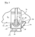
- the embodiment according to FIG. 2 differs from the embodiment according to FIG. 1 essentially in that, instead of a discrete web 24, this locking element is formed directly from the second section 20, wherein the web 24 has a rectangular profile approximately in cross-section. Instead of the rectangular profile, a right-angled trapezoidal profile can also be selected. Also in this embodiment, the web 24 is used to engage in a corresponding groove 44 of the collector 40 and to secure against slipping against the mounting rail.
- the associated collector must be adapted constructively, by forming at least one, preferably a plurality of grooves in the bottom region for receiving the third portion of the support rail or the web formed thereby 24.
- These grooves 44 preferably extend parallel or perpendicular to side surfaces of the collector 40. They can be arranged regularly or irregularly distributed over the bottom 42 of the collector 40.
- the grooves / beads 44 have the added advantage of stiffening the collector bottom 42.
Abstract
Description
Die Erfindung betrifft eine Tragschiene für einen solartechnischen Kollektor, das heißt eine Schiene zur Aufnahme und Befestigung eines solartechnischen Kollektors.The invention relates to a mounting rail for a solar collector, that is, a rail for receiving and mounting a solar collector.
Der Gegenstand der Erfindung kann Bestandteil eines komplexen Installations- und Befestigungssystems für solartechnische Kollektoren (insbesondere Warmwasser- und Photovoltaik-Kollektoren) sein, die beispielsweise auf einem Dach, in einem Dach, auf oder in einer Gebäudefassade installiert werden.The subject of the invention may be part of a complex installation and fastening system for solar thermal collectors (especially hot water and photovoltaic panels), which are installed for example on a roof, in a roof, on or in a building facade.
Die genannten Kollektoren weisen häufig ein flaches quaderförmiges Gehäuse mit Abmessungen (Breite, Länge, Höhe) von ca. 100 x 200 x 10 cm auf. Sie sind als so genannte Rahmenkollektoren oder Wannenkollektoren bekannt.The collectors mentioned often have a flat cuboid housing with dimensions (width, length, height) of about 100 x 200 x 10 cm. They are known as so-called frame collectors or pan collectors.
Bisherige Befestigungssysteme sind weitestgehend starr und können die lokalen konstruktiven Vorgaben nicht berücksichtigen. Im Ergebnis werden Kollektoren häufig schief und optisch unzureichend montiert. Insbesondere bei einer Kollektor-Montage auf einer schrägen Fläche besteht die Gefahr, dass der Kollektor auf entsprechenden Befestigungsschienen abrutscht, bevor er in die gewünschte Endposition gebracht und fixiert werden kann.Previous fastening systems are largely rigid and can not take into account the local design specifications. As a result, collectors are often installed obliquely and optically inadequate. Especially with a collector mounting on an inclined surface there is a risk that the collector slips on corresponding mounting rails before it can be brought into the desired end position and fixed.
Der Erfindung liegt insoweit die Aufgabe zugrunde, eine Tragschiene für einen solartechnischen Kollektor anzubieten, wobei die Schiene eine einfache Montage eines Befestigungsmittels erlaubt, mit dem der Kollektor an der Schiene befestigt wird. Darüber hinaus soll die Schiene eine einfache und sichere Positionierung des Kollektors bei der Montage ermöglichen.The invention is so far the object to offer a mounting rail for a solar collector, wherein the rail allows easy mounting of a fastener with which the collector is attached to the rail. In addition, the rail should allow easy and safe positioning of the collector during assembly.
Zur Lösung dieser Aufgabe sieht die Erfindung eine Tragschiene vor, die drei Abschnitte umfasst. Ein erster Abschnitt dient dazu, ein erstes Befestigungsmittel aufzunehmen, das zwischen Schiene und Kollektor geschaltet wird, um den Kollektor an der Schiene zu befestigen.To solve this problem, the invention provides a support rail, comprising three sections. A first portion serves to receive a first fastener which is connected between rail and collector to secure the collector to the rail.
Ein zweiter Abschnitt der Schiene ist dazu bestimmt, die Schiene selbst unmittelbar oder mittelbar an einer zugehörigen Auflagefläche wie einem Dach oder einer Fassade zu befestigen.A second section of the rail is intended to fix the rail itself directly or indirectly to an associated support surface such as a roof or a facade.
Der dritte Abschnitt dient dazu, den Kollektor bereits bei der Montage auf der Schiene sicher und definiert auszurichten, und zwar ohne dazu besondere Werkzeuge und/oder andere Hilfsmittel zu benötigen.The third section is used to align the collector safely and defined already during assembly on the rail, without the need for special tools and / or other aids.
Der erste Abschnitt ist so ausgebildet, dass er mindestens eine Auflagefläche für den Kollektor bildet, während der dritte Abschnitt gegenüber dieser Auflagefläche in Richtung auf den Kollektor vorsteht. Der Kollektor wird entsprechend mit einer nutartigen Vertiefung im Bodenbereich ausgebildet, die der Aufnahme des dritten Abschnitts dient, so dass es bei der Montage zu einer Verrastung zwischen dem Kollektor und dem dritten Abschnitt der Tragschiene kommt. Dadurch wird bereits während der Montagephase erreicht, dass der Kollektor nicht mehr auf der Schiene abrutschen kann, was insbesondere für Montagen auf Schrägflächen wichtig ist.The first section is designed such that it forms at least one support surface for the collector, while the third section protrudes in relation to this support surface in the direction of the collector. The collector is correspondingly formed with a groove-like depression in the bottom region, which serves to receive the third portion, so that it comes to a locking between the collector and the third portion of the mounting rail during assembly. As a result, it is already achieved during the assembly phase that the collector can no longer slide on the rail, which is particularly important for mounting on inclined surfaces.
In ihrer allgemeinsten Ausführungsform betrifft die Erfindung eine Tragschiene für einen solartechnischen Kollektor, mit folgenden Merkmalen:
- einem ersten Abschnitt, der im Querschnitt im Wesentlichen ein U-Profil aufweist mit einer Basis und zwei, von der Basis abstehenden Schenkeln,
- Endabschnitte der beiden Schenkel verlaufen zueinander fluchtend nach innen, aufeinander zu, unter Ausbildung einer schlitzförmigen Öffnung zwischen den Endabschnitten, zur Aufnahme und Festlegung eines ersten Befestigungsmittels,
- einem zweiten Abschnitt zur Aufnahme und Festlegung eines zweiten Befestigungsmittels,
- mindestens einem dritten Abschnitt, benachbart zu einem Endabschnitt eines Schenkels, wobei der dritte Abschnitt, zumindest teilweise, in Bezug auf eine Ebene, die durch Außenflächen der fluchtenden Endabschnitte der Schenkel definiert wird, in eine Richtung vorsteht, die vom ersten Abschnitt weg weist.
- a first section having in cross-section substantially a U-profile with a base and two legs projecting from the base,
- End portions of the two legs extend inwardly in alignment with each other, toward each other, forming a slit-shaped opening between the end portions, for receiving and fixing a first fastening means,
- a second section for receiving and fixing a second fastening means,
- at least a third portion adjacent an end portion of a leg, the third portion projecting, at least partially, with respect to a plane defined by outer surfaces of the aligned end portions of the legs, in a direction away from the first portion.
Bezüglich des ersten Abschnitts gilt:Regarding the first section:
Dieser Abschnitt bildet eine Aufnahme für ein erstes Befestigungsmittel. Mehrere Befestigungsmittel können an unterschiedlichen Positionen entlang einer oder mehrerer Schienen angeordnet werden, um einen oder mehrere Kollektoren festzulegen. Das Befestigungsmittel kann über die Öffnung zwischen den Endabschnitten der Schenkel in das U-Profil eingeführt werden. Danach wird das Befestigungsmittel gedreht, beispielsweise um 90°. Dazu weist der in das U-Profil eingeführte Abschnitt des Befestigungsmittels eine Form mit einer Schmalseite und einer Breitseite auf, wobei die Breitseite breiter ist als die schlitzförmige Öffnung. Dies ermöglicht es, das Befestigungsmittel mit dem in das U-Profil eingeführten Abschnitt gegen die Endabschnitte der Schenkel des ersten Abschnitts der Schiene zu führen und dort festzulegen. Dabei wirken die Endabschnitte der Schenkel des ersten Abschnitts der Tragschiene als Anschlag und Gegenlager für das Befestigungsmittel, welches an seinem gegenüberliegenden Ende am Kollektor befestigt wird. Auf diese Weise wird der Kollektor gegenüber der Tragschiene verspannt und in der gewünschten Position fixiert. Aufgrund der fluchtenden Ausrichtung der Endabschnitte der Schenkel des ersten Abschnitts der Tragschiene wird gleichzeitig eine Auflagefläche für den Boden des Kollektors geschaffen.This section forms a receptacle for a first fastener. Multiple fasteners may be disposed at different positions along one or more rails to define one or more collectors. The fastener may be inserted into the U-profile via the opening between the end portions of the legs. Thereafter, the fastening means is rotated, for example by 90 °. For this purpose, the introduced into the U-section of the fastener has a shape with a narrow side and a broad side, wherein the broad side is wider than the slot-shaped opening. This makes it possible to guide the fastener with the introduced into the U-section against the end portions of the legs of the first portion of the rail and set there. In this case, the end portions of the legs of the first portion of the support rail act as a stop and an abutment for the fastener, which is fastened at its opposite end to the collector. In this way, the collector is braced against the mounting rail and fixed in the desired position. Due to the aligned alignment of the end portions of the legs of the first portion of the support rail a bearing surface for the bottom of the collector is created at the same time.
Parallel dazu erfolgt die bereits erwähnte Verrastung des dritten Abschnitts der Tragschiene mit einer korrespondierenden Nut im Boden des Kollektors. Dabei verläuft der dritte Abschnitt im Wesentlichen parallel zur Schiene. Daraus resultiert, dass die im Kollektor angebrachte Nut bei üblicher Montage im Wesentlichen senkrecht zu den parallelen Längsseiten des Kollektors verläuft.Parallel to this, the already mentioned latching of the third section of the mounting rail with a corresponding groove in the bottom of the collector. The third section runs essentially parallel to the rail. As a result, the groove mounted in the collector is usually perpendicular to the parallel longitudinal sides of the collector with conventional mounting.
Soweit dies gewünscht wird, können auch benachbart zu beiden Endabschnitten der Schenkel des ersten Abschnitts der Tragschiene entsprechende dritte Abschnitte (Verrastungselemente) vorgesehen werden. Der Kollektor muss dann mindestens zwei der genannten Nuten aufweisen, in die die dritten Abschnitte der Tragschiene eingreifen können.As far as desired, corresponding third sections (latching elements) can also be provided adjacent to both end sections of the legs of the first section of the mounting rail. The collector must then have at least two of said grooves into which the third sections of the mounting rail can engage.
Der dritte Abschnitt verläuft beispielsweise senkrecht zu den Endabschnitten der Schenkel und entsprechend senkrecht zur Basis des genannten U-Profils des ersten Abschnitts. Der dritte Abschnitt kann zumindest in seinem, vom ersten Abschnitt wegweisenden Teil, die Form eines Steges aufweisen. Alternativ kann der dritte Abschnitt mit seinem Verrastungsteil einen Querschnitt aufweisen, der einem rechtwinkligen Trapez entspricht. Die Schrägfläche des Trapezes erleichtert das Einrasten in die korrespondierende Nut des Kollektors, während der gegenüberliegende Flächenabschnitt des Trapezes eine sichere Anlage an einer korrespondierenden Anschlagfläche in der Nut des Kollektors erlaubt.The third section extends, for example, perpendicular to the end portions of the legs and correspondingly perpendicular to the base of said U-profile of the first section. The third section can have the shape of a web, at least in its part facing away from the first section. Alternatively, the third portion with its Verrastungsteil have a cross section corresponding to a rectangular trapezoid. The inclined surface of the trapezoid facilitates the engagement in the corresponding groove of the collector, while the opposite surface portion of the trapezoid allows a secure contact with a corresponding stop surface in the groove of the collector.
Die Schenkel des ersten Abschnitts der Tragschiene verlaufen nach einer Ausführungsform senkrecht zur Basis und parallel zueinander (mit Ausnahme der Endabschnitte). Diese Endabschnitte verlaufen vorzugsweise parallel zur Basis, um die gewünschte gemeinsame Auflage für den Kollektor zu definieren.The legs of the first portion of the mounting rail according to one embodiment are perpendicular to the base and parallel to each other (with the exception of the end portions). These end portions are preferably parallel to the base to define the desired common overlay for the collector.
Eine weitere Ausführungsform der Erfindung sieht vor, die Endabschnitte an ihren freien Enden, also benachbart zu der schlitzförmigen Öffnung, mit Abkröpfungen auszubilden, die in Richtung auf die Basis des U-Profils verlaufen. Diese Abkröpfungen bilden eine zusätzliche Verrastungsmöglichkeit für das Befestigungsmittel, um dieses sicher an der Schiene festzulegen.A further embodiment of the invention provides for the end sections to be formed at their free ends, that is to say adjacent to the slot-shaped opening, with offsets which run in the direction of the base of the U-profile. These offsets provide an additional Verrastungsmöglichkeit for the fastener to securely fix this on the rail.
Auch der zweite Abschnitt kann im Querschnitt im Wesentlichen ein U-Profil aufweisen, also mit einer Basis und zwei, von der Basis abstehenden Schenkeln.The second section can also have a U-profile in cross section, that is to say with a base and two legs projecting from the base.
Die Bauform der Tragschiene wird vereinfacht, wenn die Schenkel des zweiten U-förmigen Abschnitts senkrecht zu den Schenkeln des ersten U-förmigen Abschnitts verlaufen. Dies ermöglicht es, ein zweites Befestigungsmittel seitlich, also parallel zur Basis des ersten Abschnitts, in den zweiten Abschnitt einzuführen und dort festzulegen.The design of the mounting rail is simplified when the legs of the second U-shaped portion perpendicular to the legs of the first U-shaped Section. This makes it possible to insert a second fastening means laterally, ie parallel to the base of the first section, into the second section and fix it there.
Die Bauform der Schiene wird dabei zusätzlich vereinfacht, wenn ein Schenkel des zweiten U-förmigen Abschnitts von der Basis des ersten U-förmigen Abschnitts gebildet wird. Diese Ausführungsform ist in der nachfolgenden Figurenbeschreibung näher dargestellt.The design of the rail is additionally simplified when a leg of the second U-shaped portion is formed by the base of the first U-shaped portion. This embodiment is shown in more detail in the following description of the figures.
Die Schenkel des zweiten U-förmigen Abschnitts können innenseitig eine Riffelung aufweisen. Diese Riffelung ermöglicht es, das zweite Befestigungsmittel beispielsweise mittels einer Schraube an diesem zweiten Abschnitt der Schiene zu befestigen, wobei das Gewinde der Schraube in die genannte Riffelung eingreift.The legs of the second U-shaped portion may have a corrugation on the inside. This corrugation makes it possible to attach the second fastening means, for example by means of a screw on this second portion of the rail, wherein the thread of the screw engages in said corrugation.
Bei einer Ausführungsform, bei der ein Schenkel des ersten U-förmigen Abschnitts außenseitig eine Riffelung aufweist, und zwar der Schenkel, der dem zweiten Abschnitt der Tragschiene benachbart ist, wird zusätzlich die Möglichkeit geschaffen, das zweite Befestigungsmittel in unterschiedlichen Positionen gegenüber dem ersten Abschnitt der Tragschiene festzulegen. Damit lassen sich Toleranzen bei der Montage sehr einfach ausgleichen.In an embodiment in which a leg of the first U-shaped portion has a corrugation on the outside, namely the leg, which is adjacent to the second portion of the support rail, in addition the possibility is provided, the second fastening means in different positions relative to the first portion of Determine mounting rail. This makes it very easy to compensate for tolerances during installation.
Die mindestens drei Abschnitte der Tragschiene können diskrete Abschnitte sein, die miteinander (untereinander) verbunden werden. Bevorzugt ist jedoch eine Ausführungsform, bei der erster, zweiter und dritter Abschnitt materialschlüssig miteinander verbunden sind, wobei sich diese Ausführungsform beispielsweise durch Strangpressen der Tragschiene realisieren lässt. Dies gilt sowohl für eine Tragschiene aus Metall wie für eine Tragschiene aus Kunststoff.The at least three sections of the mounting rail may be discrete sections which are connected to each other (among themselves). However, an embodiment in which the first, second and third sections are materially connected to each other is preferred, wherein this embodiment can be realized for example by extrusion of the mounting rail. This applies both to a support rail made of metal as well as for a support rail made of plastic.
Weitere Merkmale der Erfindung ergeben sich aus den Merkmalen der Unteransprüche sowie den sonstigen Anmeldungsunterlagen.Other features of the invention will become apparent from the features of the claims and the other application documents.
Die Erfindung wird nachstehend anhand eines Ausführungsbeispieles näher erläutert. Dabei zeigen, jeweils in schematisierter Darstellung,
- Figur 1:
- eine perspektivische Ansicht einer erfindungsgemäßen Tragschiene im Zusammenwirken mit einem ersten und zweiten Befestigungs- mittel und einem zugehörigen Kollektor
- Figur 2:
- eine Seitenansicht einer weiteren Ausführungsform der Tragschiene.
- FIG. 1:
- a perspective view of a support rail according to the invention in cooperation with a first and second fastening means and an associated collector
- FIG. 2:
- a side view of another embodiment of the support rail.
In den Figuren sind gleiche oder gleich wirkende Bauteile mit gleichen Bezugsziffern dargestellt. Ortsangaben wie "oben, unten, links, rechts" beziehen sich auf die dargestellte Montageposition der Tragschiene.In the figures, the same or equivalent components are shown with the same reference numerals. Location information such as "top, bottom, left, right" refer to the illustrated mounting position of the mounting rail.
Die Tragschiene gemäß
Das Befestigungsmittel 30 wird mit seinem unteren Abschnitt zur Montage durch die Öffnung 18 in den quaderförmigen Raum des ersten Abschnittes 10 eingeführt, dann um 90° in die dargestellte Position verschwenkt, und anschließend nach oben (auf hier nicht dargestellte Weise) bewegt, bis seitliche Flügel 32 des Befestigungsmittels 30 hinter die Rastschienen 14r, 16r greifen. Gleichzeitig erfolgt eine Fixierung des Kollektors 40 am gegenüberliegenden Ende des Befestigungsmittels 30, so dass im Ergebnis der Kollektor 40 über das Befestigungsmittel 30 auf der Schiene positioniert und fixiert wird. Eine analoge Befestigung mit weiteren Befestigungsmitteln erfolgt an anderer Stelle der Schiene.The
Rechts neben dem ersten Abschnitt 10 ist ein zweiter Abschnitt 20 zu erkennen, der als Hohlprofil mit Rechteckquerschnitt gestaltet ist, wobei eine obere Traverse 22 fluchtend zu den Endabschnitten 14e, 16e und in Verlängerung des Endabschnitts 16e verläuft. Von der Traverse 22 steht ein Steg 24 senkrecht nach oben ab, der in eine korrespondierende Nut 44 im Boden 42 des Kollektors 40 eingreift und diesen so gegen Verrutschen auf der Schiene sichert.To the right of the
Ein Abschnitt der Basis 12 des ersten Abschnitts 10 (in
Innenseitig weisen beide Schenkel 52, 56 eine Riffelung 58 auf. Diese Riffelung 58 dient zur Festlegung einer Gewindeschraube 60, mit deren Hilfe ein zweites Befestigungsmittel 62 an der Tragschiene festgelegt wird, wie in
Das zweite Befestigungsmittel 62 ist auf der der Tragschiene zugewandten Fläche mit einer Riffelung 64 versehen, die in eine korrespondierende Riffelung 14k auf der Außenseite des Schenkels 14 des ersten Abschnitts 10 zusammenwirkt. Wie der Figur zu entnehmen ist, ermöglichen die Riffelungen 64, 14k, das zweite Befestigungsmittel 62 in unterschiedlichen Höhen gegenüber der Tragschiene festzulegen.The second fastening means 62 is provided on the support rail facing surface with a
Profilabschnitte 70, 72 unterhalb des ersten Abschnitts 10 beziehungsweise unterhalb des dritten Abschnitts 20 ergänzen die Tragschiene so, dass sich insgesamt ein im Wesentlichen rechteckförmiger Querschnitt ergibt.
Die Ausführungsform nach
Für die erfindungsgemäße Tragschiene muss deshalb auch der zugehörige Kollektor konstruktiv angepasst werden, und zwar durch Ausbildung mindestens einer, vorzugsweise mehrerer Nuten im Bodenbereich zur Aufnahme des dritten Abschnitts der Tragschiene beziehungsweise des dadurch ausgebildeten Steges 24. Diese Nuten 44 verlaufen vorzugsweise parallel beziehungsweise senkrecht zu Seitenflächen des Kollektors 40. Sie können regelmäßig oder unregelmäßig verteilt über den Boden 42 des Kollektors 40 angeordnet werden. Die Nuten/Sicken 44 haben den zusätzlichen Vorteil einer Versteifung des Kollektorbodens 42.For the support rail according to the invention therefore also the associated collector must be adapted constructively, by forming at least one, preferably a plurality of grooves in the bottom region for receiving the third portion of the support rail or the web formed thereby 24. These
Claims (14)
Priority Applications (5)
| Application Number | Priority Date | Filing Date | Title |
|---|---|---|---|
| AT09008599T ATE554352T1 (en) | 2009-07-01 | 2009-07-01 | SOLAR COLLECTOR WITH SUPPORT RAIL |
| ES09008599T ES2383261T3 (en) | 2009-07-01 | 2009-07-01 | Solar collector with carrier rail |
| EP09008599A EP2270403B1 (en) | 2009-07-01 | 2009-07-01 | Solar collector with bearing rail |
| PT09008599T PT2270403E (en) | 2009-07-01 | 2009-07-01 | Solar collector with bearing rail |
| US12/777,381 US20110000151A1 (en) | 2009-07-01 | 2010-05-11 | Support rail |
Applications Claiming Priority (1)
| Application Number | Priority Date | Filing Date | Title |
|---|---|---|---|
| EP09008599A EP2270403B1 (en) | 2009-07-01 | 2009-07-01 | Solar collector with bearing rail |
Publications (2)
| Publication Number | Publication Date |
|---|---|
| EP2270403A1 true EP2270403A1 (en) | 2011-01-05 |
| EP2270403B1 EP2270403B1 (en) | 2012-04-18 |
Family
ID=41565890
Family Applications (1)
| Application Number | Title | Priority Date | Filing Date |
|---|---|---|---|
| EP09008599A Not-in-force EP2270403B1 (en) | 2009-07-01 | 2009-07-01 | Solar collector with bearing rail |
Country Status (5)
| Country | Link |
|---|---|
| US (1) | US20110000151A1 (en) |
| EP (1) | EP2270403B1 (en) |
| AT (1) | ATE554352T1 (en) |
| ES (1) | ES2383261T3 (en) |
| PT (1) | PT2270403E (en) |
Cited By (2)
| Publication number | Priority date | Publication date | Assignee | Title |
|---|---|---|---|---|
| WO2013033404A3 (en) * | 2011-09-01 | 2013-12-19 | Sunedison Llc | Solar module mounting bracket and assemblies |
| GB2504403A (en) * | 2011-04-12 | 2014-01-29 | Teletech Holdings Inc | Methods for providing support services via an available communication channel based on user preference and client preference |
Citations (6)
| Publication number | Priority date | Publication date | Assignee | Title |
|---|---|---|---|---|
| DE202005001469U1 (en) * | 2005-01-28 | 2005-04-07 | Wimmer Johann | Roof mounting for solar energy panels is formed from frame produced of extruded section material |
| DE202005006951U1 (en) * | 2005-04-28 | 2005-08-11 | Karner, Alfred | Mounting system for flat roof accessory elements, especially photovoltaic elements and/or solar collectors has module rails equipped with devices for anchoring of roof accessory elements of different thicknesses |
| DE102005039495A1 (en) | 2005-08-18 | 2007-03-15 | Hermann Gutmann Werke Ag | Metal profile unit for mounting system for photo voltaic unit, has receiving channel linked with units outer side over passage that is smaller than channel in cross section, and screw channel linked at front surface of receiving channel |
| DE102006053831A1 (en) | 2006-11-14 | 2008-05-15 | Fath Gmbh | Fastening device for e.g. solar module, has retaining plate including fastening section for fastening to profile rail, and another fastening section including insertion through hole for retaining pin of frame component |
| US20080172955A1 (en) * | 2005-07-11 | 2008-07-24 | Mcclintock Meredith | Solar panel and frame and related methods |
| DE102007033323A1 (en) | 2007-07-16 | 2009-01-22 | Fath Industries Gmbh | Fastening device for to be arranged on a frame structure planar components, in particular solar modules |
Family Cites Families (5)
| Publication number | Priority date | Publication date | Assignee | Title |
|---|---|---|---|---|
| US4106599A (en) * | 1977-08-29 | 1978-08-15 | Howell Alleyne C Jun | Electrification rail and joint construction |
| US7434362B2 (en) * | 2001-07-20 | 2008-10-14 | Unirac, Inc. | System for removably and adjustably mounting a device on a surface |
| MXPA06010790A (en) * | 2005-01-10 | 2007-03-26 | Conergy Ag | Threaded slider mounting system. |
| JP3907668B2 (en) * | 2005-04-07 | 2007-04-18 | シャープ株式会社 | Mounting structure of solar cell module |
| KR101467600B1 (en) * | 2008-02-11 | 2014-12-05 | 존 알. 웨스트 | Method and apparatus for forming and mounting a photovoltaic array |
-
2009
- 2009-07-01 ES ES09008599T patent/ES2383261T3/en active Active
- 2009-07-01 EP EP09008599A patent/EP2270403B1/en not_active Not-in-force
- 2009-07-01 AT AT09008599T patent/ATE554352T1/en active
- 2009-07-01 PT PT09008599T patent/PT2270403E/en unknown
-
2010
- 2010-05-11 US US12/777,381 patent/US20110000151A1/en not_active Abandoned
Patent Citations (6)
| Publication number | Priority date | Publication date | Assignee | Title |
|---|---|---|---|---|
| DE202005001469U1 (en) * | 2005-01-28 | 2005-04-07 | Wimmer Johann | Roof mounting for solar energy panels is formed from frame produced of extruded section material |
| DE202005006951U1 (en) * | 2005-04-28 | 2005-08-11 | Karner, Alfred | Mounting system for flat roof accessory elements, especially photovoltaic elements and/or solar collectors has module rails equipped with devices for anchoring of roof accessory elements of different thicknesses |
| US20080172955A1 (en) * | 2005-07-11 | 2008-07-24 | Mcclintock Meredith | Solar panel and frame and related methods |
| DE102005039495A1 (en) | 2005-08-18 | 2007-03-15 | Hermann Gutmann Werke Ag | Metal profile unit for mounting system for photo voltaic unit, has receiving channel linked with units outer side over passage that is smaller than channel in cross section, and screw channel linked at front surface of receiving channel |
| DE102006053831A1 (en) | 2006-11-14 | 2008-05-15 | Fath Gmbh | Fastening device for e.g. solar module, has retaining plate including fastening section for fastening to profile rail, and another fastening section including insertion through hole for retaining pin of frame component |
| DE102007033323A1 (en) | 2007-07-16 | 2009-01-22 | Fath Industries Gmbh | Fastening device for to be arranged on a frame structure planar components, in particular solar modules |
Cited By (2)
| Publication number | Priority date | Publication date | Assignee | Title |
|---|---|---|---|---|
| GB2504403A (en) * | 2011-04-12 | 2014-01-29 | Teletech Holdings Inc | Methods for providing support services via an available communication channel based on user preference and client preference |
| WO2013033404A3 (en) * | 2011-09-01 | 2013-12-19 | Sunedison Llc | Solar module mounting bracket and assemblies |
Also Published As
| Publication number | Publication date |
|---|---|
| US20110000151A1 (en) | 2011-01-06 |
| EP2270403B1 (en) | 2012-04-18 |
| PT2270403E (en) | 2012-06-15 |
| ATE554352T1 (en) | 2012-05-15 |
| ES2383261T3 (en) | 2012-06-19 |
Similar Documents
| Publication | Publication Date | Title |
|---|---|---|
| DE202007003060U1 (en) | connecting element | |
| EP2816172B1 (en) | Mounting system for a floor covering | |
| DE202008011312U1 (en) | Locking system for locking flat solar modules | |
| DE102018126983B4 (en) | System for attaching cladding elements to structures, structures with cladding elements attached accordingly, and methods for assembling and dismantling cladding elements | |
| DE202011001320U1 (en) | frame | |
| DE202012005671U1 (en) | Fastening device for a solar module and solar module assembly with the fastening device | |
| EP3241974B1 (en) | Assembly for a seal, in particular for a contact seal or for an automatically lowerable floor seal for doors | |
| DE19730600A1 (en) | Cuff rail fitting | |
| EP2581521B1 (en) | Device for holding an end floor board | |
| EP2270403B1 (en) | Solar collector with bearing rail | |
| EP2423622B1 (en) | Fixing device with mounting elements and supporting rail | |
| EP1837479A2 (en) | Connection arrangement for venitian blinds or similar | |
| EP1647649A2 (en) | Façade fixing system | |
| DE202011005202U1 (en) | Profile element for fixing solar modules | |
| EP3071896B1 (en) | Mounting support for a casing and method for mounting a casing using the same | |
| EP1873340B1 (en) | Door system | |
| EP3336275B1 (en) | Awning cloth fixing and guiding device | |
| DE102011050856A1 (en) | System for fixing solar modules | |
| DE102010047991A1 (en) | Fastening system for cable transition apparatus in mast, has clips provided with holding part, which is snapped open on rail and connected with transition apparatus, and lateral edges of mast with radial portions run in inner side of mast | |
| DE202007008150U1 (en) | Fixing device for solar modules | |
| EP1801307B1 (en) | Snow guard for inclined roof surfaces | |
| DE202004021147U1 (en) | Support structure for panels, at an outer building wall, has a grid of vertical and horizontal rails with sliding panel carrier clips and a hook-shaped fastener to lock the horizontal rail at the vertical member | |
| DE102017207494B4 (en) | Assembly device and assembly method for wall or roof panels with a wave-like or trapezoidal cross-section | |
| DE102017009086B4 (en) | Holding system for roof tiles | |
| DE202019107234U1 (en) | Holding body for forming a mounting rail for a support grid of a suspended ceiling or mounting rail with a holding body |
Legal Events
| Date | Code | Title | Description |
|---|---|---|---|
| PUAI | Public reference made under article 153(3) epc to a published international application that has entered the european phase |
Free format text: ORIGINAL CODE: 0009012 |
|
| 17P | Request for examination filed |
Effective date: 20100313 |
|
| AK | Designated contracting states |
Kind code of ref document: A1 Designated state(s): AT BE BG CH CY CZ DE DK EE ES FI FR GB GR HR HU IE IS IT LI LT LU LV MC MK MT NL NO PL PT RO SE SI SK SM TR |
|
| AX | Request for extension of the european patent |
Extension state: AL BA RS |
|
| 17Q | First examination report despatched |
Effective date: 20110526 |
|
| GRAP | Despatch of communication of intention to grant a patent |
Free format text: ORIGINAL CODE: EPIDOSNIGR1 |
|
| GRAJ | Information related to disapproval of communication of intention to grant by the applicant or resumption of examination proceedings by the epo deleted |
Free format text: ORIGINAL CODE: EPIDOSDIGR1 |
|
| GRAP | Despatch of communication of intention to grant a patent |
Free format text: ORIGINAL CODE: EPIDOSNIGR1 |
|
| RTI1 | Title (correction) |
Free format text: SOLAR COLLECTOR WITH BEARING RAIL |
|
| GRAS | Grant fee paid |
Free format text: ORIGINAL CODE: EPIDOSNIGR3 |
|
| GRAA | (expected) grant |
Free format text: ORIGINAL CODE: 0009210 |
|
| AK | Designated contracting states |
Kind code of ref document: B1 Designated state(s): AT BE BG CH CY CZ DE DK EE ES FI FR GB GR HR HU IE IS IT LI LT LU LV MC MK MT NL NO PL PT RO SE SI SK SM TR |
|
| REG | Reference to a national code |
Ref country code: GB Ref legal event code: FG4D Free format text: NOT ENGLISH |
|
| REG | Reference to a national code |
Ref country code: CH Ref legal event code: EP |
|
| REG | Reference to a national code |
Ref country code: IE Ref legal event code: FG4D Free format text: LANGUAGE OF EP DOCUMENT: GERMAN |
|
| REG | Reference to a national code |
Ref country code: AT Ref legal event code: REF Ref document number: 554352 Country of ref document: AT Kind code of ref document: T Effective date: 20120515 Ref country code: CH Ref legal event code: NV Representative=s name: HANS RUDOLF GACHNANG PATENTANWALT |
|
| REG | Reference to a national code |
Ref country code: DE Ref legal event code: R096 Ref document number: 502009003252 Country of ref document: DE Effective date: 20120614 |
|
| REG | Reference to a national code |
Ref country code: PT Ref legal event code: SC4A Free format text: AVAILABILITY OF NATIONAL TRANSLATION Effective date: 20120601 |
|
| REG | Reference to a national code |
Ref country code: ES Ref legal event code: FG2A Ref document number: 2383261 Country of ref document: ES Kind code of ref document: T3 Effective date: 20120619 |
|
| REG | Reference to a national code |
Ref country code: NL Ref legal event code: VDEP Effective date: 20120418 |
|
| LTIE | Lt: invalidation of european patent or patent extension |
Effective date: 20120418 |
|
| PG25 | Lapsed in a contracting state [announced via postgrant information from national office to epo] |
Ref country code: NO Free format text: LAPSE BECAUSE OF FAILURE TO SUBMIT A TRANSLATION OF THE DESCRIPTION OR TO PAY THE FEE WITHIN THE PRESCRIBED TIME-LIMIT Effective date: 20120718 Ref country code: LT Free format text: LAPSE BECAUSE OF FAILURE TO SUBMIT A TRANSLATION OF THE DESCRIPTION OR TO PAY THE FEE WITHIN THE PRESCRIBED TIME-LIMIT Effective date: 20120418 Ref country code: PL Free format text: LAPSE BECAUSE OF FAILURE TO SUBMIT A TRANSLATION OF THE DESCRIPTION OR TO PAY THE FEE WITHIN THE PRESCRIBED TIME-LIMIT Effective date: 20120418 Ref country code: CY Free format text: LAPSE BECAUSE OF FAILURE TO SUBMIT A TRANSLATION OF THE DESCRIPTION OR TO PAY THE FEE WITHIN THE PRESCRIBED TIME-LIMIT Effective date: 20120418 Ref country code: FI Free format text: LAPSE BECAUSE OF FAILURE TO SUBMIT A TRANSLATION OF THE DESCRIPTION OR TO PAY THE FEE WITHIN THE PRESCRIBED TIME-LIMIT Effective date: 20120418 Ref country code: SE Free format text: LAPSE BECAUSE OF FAILURE TO SUBMIT A TRANSLATION OF THE DESCRIPTION OR TO PAY THE FEE WITHIN THE PRESCRIBED TIME-LIMIT Effective date: 20120418 Ref country code: IS Free format text: LAPSE BECAUSE OF FAILURE TO SUBMIT A TRANSLATION OF THE DESCRIPTION OR TO PAY THE FEE WITHIN THE PRESCRIBED TIME-LIMIT Effective date: 20120818 |
|
| PG25 | Lapsed in a contracting state [announced via postgrant information from national office to epo] |
Ref country code: GR Free format text: LAPSE BECAUSE OF FAILURE TO SUBMIT A TRANSLATION OF THE DESCRIPTION OR TO PAY THE FEE WITHIN THE PRESCRIBED TIME-LIMIT Effective date: 20120719 Ref country code: SI Free format text: LAPSE BECAUSE OF FAILURE TO SUBMIT A TRANSLATION OF THE DESCRIPTION OR TO PAY THE FEE WITHIN THE PRESCRIBED TIME-LIMIT Effective date: 20120418 Ref country code: LV Free format text: LAPSE BECAUSE OF FAILURE TO SUBMIT A TRANSLATION OF THE DESCRIPTION OR TO PAY THE FEE WITHIN THE PRESCRIBED TIME-LIMIT Effective date: 20120418 Ref country code: HR Free format text: LAPSE BECAUSE OF FAILURE TO SUBMIT A TRANSLATION OF THE DESCRIPTION OR TO PAY THE FEE WITHIN THE PRESCRIBED TIME-LIMIT Effective date: 20120418 |
|
| BERE | Be: lapsed |
Owner name: GREENONETEC Effective date: 20120731 |
|
| PG25 | Lapsed in a contracting state [announced via postgrant information from national office to epo] |
Ref country code: EE Free format text: LAPSE BECAUSE OF FAILURE TO SUBMIT A TRANSLATION OF THE DESCRIPTION OR TO PAY THE FEE WITHIN THE PRESCRIBED TIME-LIMIT Effective date: 20120418 Ref country code: DK Free format text: LAPSE BECAUSE OF FAILURE TO SUBMIT A TRANSLATION OF THE DESCRIPTION OR TO PAY THE FEE WITHIN THE PRESCRIBED TIME-LIMIT Effective date: 20120418 Ref country code: SK Free format text: LAPSE BECAUSE OF FAILURE TO SUBMIT A TRANSLATION OF THE DESCRIPTION OR TO PAY THE FEE WITHIN THE PRESCRIBED TIME-LIMIT Effective date: 20120418 Ref country code: NL Free format text: LAPSE BECAUSE OF FAILURE TO SUBMIT A TRANSLATION OF THE DESCRIPTION OR TO PAY THE FEE WITHIN THE PRESCRIBED TIME-LIMIT Effective date: 20120418 Ref country code: RO Free format text: LAPSE BECAUSE OF FAILURE TO SUBMIT A TRANSLATION OF THE DESCRIPTION OR TO PAY THE FEE WITHIN THE PRESCRIBED TIME-LIMIT Effective date: 20120418 Ref country code: CZ Free format text: LAPSE BECAUSE OF FAILURE TO SUBMIT A TRANSLATION OF THE DESCRIPTION OR TO PAY THE FEE WITHIN THE PRESCRIBED TIME-LIMIT Effective date: 20120418 |
|
| PLBE | No opposition filed within time limit |
Free format text: ORIGINAL CODE: 0009261 |
|
| STAA | Information on the status of an ep patent application or granted ep patent |
Free format text: STATUS: NO OPPOSITION FILED WITHIN TIME LIMIT |
|
| PG25 | Lapsed in a contracting state [announced via postgrant information from national office to epo] |
Ref country code: MC Free format text: LAPSE BECAUSE OF NON-PAYMENT OF DUE FEES Effective date: 20120731 Ref country code: MK Free format text: LAPSE BECAUSE OF FAILURE TO SUBMIT A TRANSLATION OF THE DESCRIPTION OR TO PAY THE FEE WITHIN THE PRESCRIBED TIME-LIMIT Effective date: 20120418 |
|
| 26N | No opposition filed |
Effective date: 20130121 |
|
| REG | Reference to a national code |
Ref country code: IE Ref legal event code: MM4A |
|
| REG | Reference to a national code |
Ref country code: DE Ref legal event code: R097 Ref document number: 502009003252 Country of ref document: DE Effective date: 20130121 |
|
| PG25 | Lapsed in a contracting state [announced via postgrant information from national office to epo] |
Ref country code: BE Free format text: LAPSE BECAUSE OF NON-PAYMENT OF DUE FEES Effective date: 20120731 |
|
| PG25 | Lapsed in a contracting state [announced via postgrant information from national office to epo] |
Ref country code: IE Free format text: LAPSE BECAUSE OF NON-PAYMENT OF DUE FEES Effective date: 20120701 Ref country code: BG Free format text: LAPSE BECAUSE OF FAILURE TO SUBMIT A TRANSLATION OF THE DESCRIPTION OR TO PAY THE FEE WITHIN THE PRESCRIBED TIME-LIMIT Effective date: 20120718 Ref country code: MT Free format text: LAPSE BECAUSE OF FAILURE TO SUBMIT A TRANSLATION OF THE DESCRIPTION OR TO PAY THE FEE WITHIN THE PRESCRIBED TIME-LIMIT Effective date: 20120418 |
|
| REG | Reference to a national code |
Ref country code: CH Ref legal event code: NV Representative=s name: GACHNANG AG PATENTANWAELTE, CH |
|
| PG25 | Lapsed in a contracting state [announced via postgrant information from national office to epo] |
Ref country code: TR Free format text: LAPSE BECAUSE OF FAILURE TO SUBMIT A TRANSLATION OF THE DESCRIPTION OR TO PAY THE FEE WITHIN THE PRESCRIBED TIME-LIMIT Effective date: 20120418 |
|
| PG25 | Lapsed in a contracting state [announced via postgrant information from national office to epo] |
Ref country code: SM Free format text: LAPSE BECAUSE OF FAILURE TO SUBMIT A TRANSLATION OF THE DESCRIPTION OR TO PAY THE FEE WITHIN THE PRESCRIBED TIME-LIMIT Effective date: 20120418 Ref country code: LU Free format text: LAPSE BECAUSE OF NON-PAYMENT OF DUE FEES Effective date: 20120701 |
|
| PG25 | Lapsed in a contracting state [announced via postgrant information from national office to epo] |
Ref country code: HU Free format text: LAPSE BECAUSE OF FAILURE TO SUBMIT A TRANSLATION OF THE DESCRIPTION OR TO PAY THE FEE WITHIN THE PRESCRIBED TIME-LIMIT Effective date: 20090701 |
|
| REG | Reference to a national code |
Ref country code: FR Ref legal event code: PLFP Year of fee payment: 7 |
|
| PGFP | Annual fee paid to national office [announced via postgrant information from national office to epo] |
Ref country code: PT Payment date: 20150624 Year of fee payment: 7 |
|
| PGFP | Annual fee paid to national office [announced via postgrant information from national office to epo] |
Ref country code: DE Payment date: 20150729 Year of fee payment: 7 Ref country code: ES Payment date: 20150723 Year of fee payment: 7 Ref country code: CH Payment date: 20150723 Year of fee payment: 7 Ref country code: GB Payment date: 20150724 Year of fee payment: 7 |
|
| PGFP | Annual fee paid to national office [announced via postgrant information from national office to epo] |
Ref country code: AT Payment date: 20150722 Year of fee payment: 7 Ref country code: FR Payment date: 20150730 Year of fee payment: 7 |
|
| PGFP | Annual fee paid to national office [announced via postgrant information from national office to epo] |
Ref country code: IT Payment date: 20150728 Year of fee payment: 7 |
|
| REG | Reference to a national code |
Ref country code: DE Ref legal event code: R119 Ref document number: 502009003252 Country of ref document: DE |
|
| REG | Reference to a national code |
Ref country code: CH Ref legal event code: PL |
|
| REG | Reference to a national code |
Ref country code: AT Ref legal event code: MM01 Ref document number: 554352 Country of ref document: AT Kind code of ref document: T Effective date: 20160701 |
|
| GBPC | Gb: european patent ceased through non-payment of renewal fee |
Effective date: 20160701 |
|
| PG25 | Lapsed in a contracting state [announced via postgrant information from national office to epo] |
Ref country code: FR Free format text: LAPSE BECAUSE OF NON-PAYMENT OF DUE FEES Effective date: 20160801 Ref country code: CH Free format text: LAPSE BECAUSE OF NON-PAYMENT OF DUE FEES Effective date: 20160731 Ref country code: DE Free format text: LAPSE BECAUSE OF NON-PAYMENT OF DUE FEES Effective date: 20170201 Ref country code: LI Free format text: LAPSE BECAUSE OF NON-PAYMENT OF DUE FEES Effective date: 20160731 |
|
| REG | Reference to a national code |
Ref country code: FR Ref legal event code: ST Effective date: 20170331 |
|
| PG25 | Lapsed in a contracting state [announced via postgrant information from national office to epo] |
Ref country code: PT Free format text: LAPSE BECAUSE OF NON-PAYMENT OF DUE FEES Effective date: 20170102 Ref country code: GB Free format text: LAPSE BECAUSE OF NON-PAYMENT OF DUE FEES Effective date: 20160701 Ref country code: AT Free format text: LAPSE BECAUSE OF NON-PAYMENT OF DUE FEES Effective date: 20160701 |
|
| PG25 | Lapsed in a contracting state [announced via postgrant information from national office to epo] |
Ref country code: IT Free format text: LAPSE BECAUSE OF NON-PAYMENT OF DUE FEES Effective date: 20160701 |
|
| PG25 | Lapsed in a contracting state [announced via postgrant information from national office to epo] |
Ref country code: ES Free format text: LAPSE BECAUSE OF NON-PAYMENT OF DUE FEES Effective date: 20160702 |
|
| REG | Reference to a national code |
Ref country code: ES Ref legal event code: FD2A Effective date: 20181126 |