EP2272557A2 - Suction catheter assembly - Google Patents
Suction catheter assembly Download PDFInfo
- Publication number
- EP2272557A2 EP2272557A2 EP10013963A EP10013963A EP2272557A2 EP 2272557 A2 EP2272557 A2 EP 2272557A2 EP 10013963 A EP10013963 A EP 10013963A EP 10013963 A EP10013963 A EP 10013963A EP 2272557 A2 EP2272557 A2 EP 2272557A2
- Authority
- EP
- European Patent Office
- Prior art keywords
- adaptor
- housing
- release
- assembly
- tracheostomy tube
- Prior art date
- Legal status (The legal status is an assumption and is not a legal conclusion. Google has not performed a legal analysis and makes no representation as to the accuracy of the status listed.)
- Granted
Links
Images


Classifications
-
- A—HUMAN NECESSITIES
- A61—MEDICAL OR VETERINARY SCIENCE; HYGIENE
- A61M—DEVICES FOR INTRODUCING MEDIA INTO, OR ONTO, THE BODY; DEVICES FOR TRANSDUCING BODY MEDIA OR FOR TAKING MEDIA FROM THE BODY; DEVICES FOR PRODUCING OR ENDING SLEEP OR STUPOR
- A61M16/00—Devices for influencing the respiratory system of patients by gas treatment, e.g. mouth-to-mouth respiration; Tracheal tubes
- A61M16/04—Tracheal tubes
- A61M16/0463—Tracheal tubes combined with suction tubes, catheters or the like; Outside connections
-
- A—HUMAN NECESSITIES
- A61—MEDICAL OR VETERINARY SCIENCE; HYGIENE
- A61M—DEVICES FOR INTRODUCING MEDIA INTO, OR ONTO, THE BODY; DEVICES FOR TRANSDUCING BODY MEDIA OR FOR TAKING MEDIA FROM THE BODY; DEVICES FOR PRODUCING OR ENDING SLEEP OR STUPOR
- A61M16/00—Devices for influencing the respiratory system of patients by gas treatment, e.g. mouth-to-mouth respiration; Tracheal tubes
- A61M16/04—Tracheal tubes
- A61M16/0465—Tracheostomy tubes; Devices for performing a tracheostomy; Accessories therefor, e.g. masks, filters
- A61M16/047—Masks, filters, surgical pads, devices for absorbing secretions, specially adapted therefor
-
- A—HUMAN NECESSITIES
- A61—MEDICAL OR VETERINARY SCIENCE; HYGIENE
- A61M—DEVICES FOR INTRODUCING MEDIA INTO, OR ONTO, THE BODY; DEVICES FOR TRANSDUCING BODY MEDIA OR FOR TAKING MEDIA FROM THE BODY; DEVICES FOR PRODUCING OR ENDING SLEEP OR STUPOR
- A61M16/00—Devices for influencing the respiratory system of patients by gas treatment, e.g. mouth-to-mouth respiration; Tracheal tubes
- A61M16/10—Preparation of respiratory gases or vapours
- A61M16/1045—Devices for humidifying or heating the inspired gas by using recovered moisture or heat from the expired gas
Abstract
Description
- The present invention relates generally to closed suction catheter assemblies used in respiratory applications.
- There are a number of different circumstances in which it is necessary for a person to have an artificial airway, such as a tracheostomy tube, placed in his or her respiratory tract. As used herein, the phrase "artificial airway" includes devices such as tracheostomy tubes, endotracheal tubes, and the like. Artificial airways keep the patient's natural airway open so that adequate lung ventilation can be maintained.
- In certain situations, patients may have a need for an artificial airway such as a tracheostomy tube while not necessarily requiring artificial or assisted respiration. For example, during-surgery a tracheostomy tube may be used to facilitate the administration of anesthesia and to help ensure that oxygenation levels remain within acceptable ranges.
- In other situations, the artificial airway must be left in the patient for a prolonged period of time. For example, many persons suffering severe neck or head trauma use a tracheostomy tube in conjunction with mechanical ventilation during extended recovery and rehabilitation periods. The patient's medical condition may require that they remain in a prone position for an extended period of time. In these situations, mucous and other secretions tend to pool in the lungs, and the patients may not be able to expel such secretions from their lungs. Additionally, the presence of the tracheostomy tube itself causes an increased amount of secretions that tend to gather around and adhere to the tracheostomy tube.
- Thus, when an artificial airway is used, it is critical that respiratory secretions be periodically removed. This is typically accomplished by the use of a respiratory suction catheter that is advanced into and through the tracheostomy tube. As the suction catheter is withdrawn, a negative pressure (or vacuum) is applied to draw mucus and other secretions from the patient's airways and the interior of the artificial airway. While a substantial amount of the mucus and other secretions will be withdrawn through the lumen of the suction catheter, a portion of the mucus and other secretions will remain as a film on the outside of the catheter.
- In a closed suction catheter assembly, as set forth in
U.S. Patent Nos. 3,991,762 and4,569,344 , the catheter may be enveloped by a protective sleeve and include a valve mechanism disposed near the vacuum source. These features reduce the risk of contamination to both the patient and the care giver. At its distal end, the closed suction catheter may be attached to an artificial airway via one of a variety of connectors, including, for example, a multi-legged tracheostomy connector. One of the legs of the tracheostomy connector may be connected to a tracheostomy tube located within an aperture formed in the throat of the patient. When it is desired to remove secretions or mucus from the patient, the catheter is advanced through the connector and into the tracheostomy tube. Negative pressure is then applied to the other end of the catheter and secretions within the patient's respiratory system are evacuated. With the use of the closed suction catheter assembly, the ventilating circuit need not be detached from the patient during suctioning, and a single catheter may be used for an extended period, typically a 24-hour period. - Patient secretions can contain infectious agents, such as streptococcus, pseudomonas, staphylococcus, and even HIV. It is, therefore, important to shield the clinician from contact with the catheter. Using an uncovered catheter, or "open" catheter, poses health risks to the clinician. When the catheter is withdrawn from the tracheostomy tube, the exterior of the catheter may be coated with patient secretions. If all of the obstructions are removed, the catheter can be discarded. Often, however, it is necessary to repeat the procedure two or three times. With each advancement and retraction of the catheter, the clinician has to be concerned both about suctioning the patient and avoiding contact with the potentially infectious agents on the exterior of the catheter. In addition, the clinician must be concerned with preventing the catheter from being accidentally contaminated with microbes from the surrounding area, for example the patient's gown, bed clothing, and other surrounding items which may transmit microbes.
- It is, therefore, equally as important to shield the patient from communicable pathogens in the environment and those that may be carried by the clinician. This is particularly important because patients having tracheostomy tubes often have compromised immune systems and may be more susceptible to respiratory infections.
- A problem arises with repeated attachment and detachment of the catheter assembly to a tracheostomy tube since the constant application of force against the tracheostomy tube causes irritation and discomfort to the patient. Another problem posed with repeated attachment and detachment of the catheter assembly is that two hands are generally required. One hand stabilizes the tracheostomy tube while the other pushes the distal end of the catheter assembly onto the tracheostomy tube or pulls the distal end away from the tracheostomy tube. (As used herein, "distal" refers to the direction of the patient and "proximal" refers to the direction of the clinician.)
- Thus, there is a need for an adaptor for attachment of a closed suction catheter assembly to a tracheostomy tube or other artificial airway that effectively addresses at least some of the problems noted with conventional closed suction catheter assemblies.
- Objects and advantages of the invention of the invention will be set forth in part in the following description, or may be obvious from the description, or may be learned through practice of the invention.
- The present invention is directed to an adaptor for use with a closed suction catheter assembly for attachment to an artificial airway, such as a tracheostomy tube. The adaptor is configured to permit engagement with an artificial airway, such as a tracheostomy tube, while simultaneously allowing the patient to breathe through the adaptor. In one embodiment, a series of projections or ribs extend radially inward within the housing of the adaptor, thereby defining channels which enable the patient's ability to breathe.
- The adaptor of the invention further may contain within the housing an oxygen port for patients having compromised {respiratory capacity}[ability to maintain oxygen saturation]. As such, the oxygen port permits the introduction of oxygen {enriched air}-to the patient.
- The adaptor of the invention also may contain a means for cleaning mucus and other secretions from the external surface of the catheter. In a preferred embodiment, the housing of the adaptor may have a lavage port to assist in cleaning. The adaptor of the invention may also have a cover for isolation of the catheter of the closed suction catheter assembly from the atmosphere during cleaning.
- Further, the adaptor of the invention, when used with a closed suction catheter assembly, safeguards the clinician from contamination by keeping the external surface of the catheter either within the protective sleeve of the closed suction catheter assembly or within the adaptor housing. The isolation of the catheter further safeguards the patient by keeping microbes and other surrounding contaminants away from the external surface of the catheter.
- The adaptor of the invention also facilitates release of the closed suction catheter assembly from the tracheostomy tube and, thus, the patient. The release assembly may include an extension mechanism attached to a release member. When force is applied to the release assembly, the distal end of the closed suction catheter assembly disengages itself from the adaptor flange of the tracheostomy tube. The adaptor of the invention permits single-handed detachment without undue movement of the tracheostomy tube.
- In accordance with another aspect of the invention, the adaptor is formed with a release plate and a pair of arms which attach the plate to the closed suction catheter assembly. The arms are formed so that when pressure is applied thereto, the arms extend, causing the release plate to disengage the adaptor flange of the tracheostomy tube, forcing the distal end of the catheter assembly to move away from the proximal end of the tracheostomy tube.
- In accordance with another aspect of the present invention, the release plate is movable so that a portion of the plate covers the distal end of the catheter to help prevent cross-contamination.
- {In another embodiment, the adaptor of the invention includes a filter for patients who require filtered air}
- In accordance with still yet another aspect of the invention , the release mechanism and the filter form an integrated adaptor unit which is detachable from the closed suction catheter assembly and the tracheostomy tube.
- In accordance with yet another aspect of the present invention, the release assembly can be integrated with the manifold of a closed suction catheter assembly which is configured for use on a ventilated patient.
- In accordance with a first aspect of the invention there is provided an adaptor for connecting a closed suction catheter system to a tracheostomy tube comprising a housing having: an internal chamber defined by a plurality of (a) ribs and (b) channels disposed between the ribs; a distal end configured internally to engage the proximal end of the tracheostomy tube; and a proximal end to engage the distal end of the closed suction catheter assembly. In embodiments the ribs are radially inwardly extending ribs, and said channels formed between said ribs enable inhalation and exhalation by a patient through the housing when the adaptor is in engagement with a tracheostomy tube.
- In embodiments, the housing may have an oxygen port.
- The adaptor may have a release assembly separating the housing of the adaptor from the tracheostomy tube. The release assembly may contain a release plate having an aperture formed therein and wherein the release plate is slidable to move the aperture into and out of alignment withy the internal chamber of the housing. The release assembly may contain at least one arm configured for extending distally from the adaptor. The release assembly may contain a first arm and a second arm. The first arm and the second arm may be attached by a retaining ring, or the first arm and the second arm may be attached to an annular disk defining an aperture. The release assembly may consist of a release member disposed at the distal end of the adaptor and which may be extended distally to disengage the housing from the tracheostomy tube.
- In accordance with a second aspect of the invention, there is provided an adaptor connecting a closed suction catheter system to a tracheostomy tube comprising a housing having: a distal end configured internally to engage the proximal end of the tracheostomy tube; a proximal end to engage the distal end of the closed suction catheter assembly; and a release assembly for separating the housing of the adaptor from the tracheostomy tube.
- The housing may have an oxygen port.
- The release assembly may contain a release plate having an aperture formed therein and wherein the release plate is slidable to move the aperture into and out of alignment with the internal chamber of the housing.
- The release assembly may contain at least one arm configured for extending distally from the adaptor. The release assembly may contain a first arm and a second arm. The first arm and the second arm may be attached by a retaining ring, or the first arm and the second arm may be attached to an annular disk defining an aperture.
- The release assembly may consist of a release member disposed at the distal end of the adaptor and which may be extended distally to disengage the housing from the tracheostomy tube.
- The adaptor housing may include a manifold having a first barrel, a second barrel and a third barrel, the first and second barrels being substantially in alignment and the third barrel extending perpendicularly thereto. The manifold may further contain a fourth barrel.
- The housing may further contain a filter housing and a filter within the filter housing.
- In accordance with a third aspect of the invention, there is provided an adaptor for connecting a closed suction catheter system to a tracheostomy tube comprising a housing having: a distal end configured internally to engage the proximal end of the tracheostomy tube; a proximal end to engage the distal end of the closed suction catheter assembly; a filter housing; and a filter within the filter housing.
- The housing may have an oxygen port.
- The adaptor may have a release assembly for separating the housing of the adaptor from the tracheostomy tube, wherein the release assembly contains a release plate having an aperture formed therein and wherein the release plate is slidable to move the aperture into and out of alignment with the internal chamber of the housing. The release assembly contains at least one arm configured for extending distally from the adaptor. The release assembly may contain a first arm and a second arm.
- The present invention provides a catheter system comprising: a closed suction catheter assembly; and the adaptor in accordance with the first, second or third aspect of the invention.
- In accordance with a fourth aspect, the present invention provides an apparatus for suctioning secretions from a patient intubated with a tracheostomy tube, the apparatus comprising: a closed suction catheter assembly having a catheter and an envelope surrounding the catheter tube; an adaptor disposed at the distal end of the closed suction catheter assembly, the catheter tube being advanceable therethrough; and a cover attached to the distal end of the adaptor having an end wall for sealing the adaptor from the atmosphere, a small hole disposed in the end wall.
- The cover may further comprise a cap for selectively preventing flow of fluid through the hole.
- In accordance with a fifth aspect, the present invention provides an apparatus for suctioning secretions from a patient intubated with a tracheostomy tube comprising: a closed suction catheter assembly having a catheter tube, an envelope and a coupling for holding an end of the envelope; and an adaptor disposed at the distal end of the closed suction catheter assembly and having a housing configured for attachment to a tracheostomy tube and a release assembly disposed adjacent the housing, the release assembly being configured for detaching the housing from the tracheostomy tube responsive to a compressive force to the release assembly.
- The release assembly may comprise a release member disposed at a distal end of the adaptor and being extendable distally to disengage the housing of the adaptor from a tracheostomy tube. The release member may be slidable. The release member may have an aperture formed therein. The aperture may be fluted.
- The adaptor may further comprise a filter.
-
-
FIG. 1 is a perspective view of a distal end of a closed suction catheter system for attachment to a tracheostomy tube; -
FIG. 2 is a perspective view of a closed suction catheter system having a release adaptor disposed at the distal end of the closed suction catheter assembly in accordance with the principles of the present invention; -
FIG. 3 is a side view of the distal end of the closed suction catheter system ofFIG. 2 in alignment for attachment to a tracheostomy tube; -
FIG. 4 is a close-up perspective view of the closed suction catheter system ofFIGS. 2 and3 with the release adaptor configured for attachment to a tracheostomy tube; -
FIG. 5 is a close-up perspective view similar to that ofFIG. 4 , but with the release adaptor configured to substantially isolate the catheter assembly from contamination while the assembly is not in use; -
FIG. 6 is a close-up perspective view of a release assembly apart from the adaptor onto which it is typically mounted; -
FIG. 7 is a close-up perspective view of an alternate embodiment of the invention wherein a filter is integrated into an adaptor with a release mechanism; -
FIG. 8 is a close-up perspective view of the partially disassembled release assembly ofFIG. 7 demonstrating an alternative method of assembling the release mechanism; -
FIG. 9 is a close-up perspective view of yet another embodiment wherein the filter and the release mechanism are formed in an adaptor which is detachable from the remainder of the closed suction catheter system; -
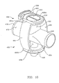
FIG. 10 is a perspective view of an adaptor for use with a closed suction catheter assembly which is used on patients requiring mechanical ventilation; -
FIG. 11 is a perspective view of the release assembly ofFIG. 10 taken from the proximal end of the assembly; and -
FIG. 12 is a perspective view of another embodiment of an adaptor for use on patients who are receiving mechanical ventilation. - Reference will now be made in detail to embodiments of the invention, one or more examples of which are shown in the drawings. It should be appreciated that each example is provided by way of explaining the invention, and not as a limitation of the invention. For example, features illustrated or described with respect to one embodiment may be used with another embodiment to yield still a further embodiment. Such modifications and variations are within the scope and spirit of the invention.
-
FIG. 1 is a perspective view of a closedsuction catheter assembly 100 including a closedsuction catheter system 50 having a distal end with the present inventive adaptor. The closedsuction catheter system 50 is positioned for attachment to an artificial airway, in particular totracheostomy tube 104. Thecatheter assembly 100 typically includes anelongate catheter 108 which may be advanced through thedistal end 100a of thecatheter assembly 100. - The
elongate catheter 108 is surrounded or shielded by aflexible envelope 112 which extends substantially along the length of thecatheter 108. Theenvelope 112 is secured at itsdistal end 112a by acoupling 116 which contains an opening through which thecatheter 108 can be advanced and withdrawn. The coupling may include a snap-fit connection between an outer ring and an inner ring. - Disposed distally from the
coupling 116 is anadaptor 120 according to the present invention configured to secure the closedsuction catheter assembly 100 to anadaptor barrel 124 at theproximal end 104b of thetracheostomy tube 104. In the illustrated embodiment, theadaptor 120 includes a bell-shapedhousing 128 which has a distal end configured to engage the exterior of theadaptor barrel 124 of thetracheostomy tube 104. To enable engagement while simultaneously allowing the patient to breathe through theadaptor 120, a series of projections orribs 132 extend radially inward from thehousing 128 to engage theadaptor barrel 124. A plurality ofchannels 136 are formed between theribs 132 to enable inhalation and exhalation through thehousing 128. - The
housing 128 can also have anoxygen port 140 formed therein through which oxygen enriched air can be supplied to the patient. This is particularly important for a patient with compromised respiratory capacity necessitating that the patient have indwelling tracheostomy tubes The housing may also have alavage port 144 which can be used to inject fluids into the tracheostomy tube. Thelavage port 144 may also be used to clean thecatheter 108. - The closed
suction catheter system 50 may also include acover 150 which engages thehousing 128 to substantially isolate thecatheter tube 108 from the outside environment. The cover may be attached to the distal end of the closedsuction catheter assembly 100 or the proximal end ofhousing 128. Thecover 150 serves various purposes, as discussed in greater detail below. - Immediately after use, it is important to clean the exterior of the
catheter 108. If left uncleaned, mucus and other secretions dry on thecatheter 108, reducing its effectiveness in future uses. The mucus can also serve as a breeding ground for microbes. Thecover 150 assists in cleaning thecatheter 108 by providing a restricted airflow into the distal end of the catheter tube. This is accomplished by acap 152 which includes a wall 154 having asmall hole 158 to form a metering valve. Thehole 158 allows a small quantity of air to enter as suction is applied through thecatheter 108 to restrict airflow into the catheter. It has been found that providing such a restricted airflow helps to improve cleaning of the distal end of thecatheter 108. - A
secondary cap 162 may be provided to selectively close the valve formed by the wall 154 and thehole 158. Thesecondary cap 162 essentially isolates the distal end of thecatheter 108 from the atmosphere and potential contaminants coming through thehousing 128. This is important, as the closedsuction catheter system 50 may be attached and removed from the tracheostomy tube numerous times during use. Thecover 150 helps prevent the closed suction catheter system from being contaminated by contact with contaminants in the atmosphere. In order to use the closedsuction catheter system 50 again, thecover 150 is removed and theadaptor housing 128 is reattached to theadaptor barrel 124 of thetracheostomy tube 104. To prevent excess movement of thetracheostomy tube 104, the clinician will typically hold theadaptor flange 170 of thetracheostomy tube 104 as theribs 132 of theadaptor housing 128 are brought into frictional engagement with theadaptor barrel 124. -
FIG. 2 shows theproximal coupling 174 of theenvelope 112, and asuction control valve 178 which were not shown inFIG. 1 . Thesuction control valve 178 has aproximal end 178b which connects to a tube attached to suction. Referring toFIG. 2 , the adaptor also includes arelease assembly 180 which is attached to theadaptor housing 128. Therelease assembly 180 includes afirst arm 184 and asecond arm 188. Aproximal end 184b of thefirst arm 184 and aproximal end 188b of thesecond arm 188 are connected to thehousing 128. An opposingdistal end 184a of thefirst arm 184 and an opposingdistal end 188a of thesecond arm 188 are attached to anelongate release member 192 having anaperture 200 at one end. Theaperture 200 includes a plurality offlutes 204 which are generally in alignment with thechannels 136 in thehousing 128 to facilitate breathing by the patient. - When the
housing 128 is attached to thetracheostomy tube 104, therelease member 192 is disposed adjacent to theadaptor flange 170. Applying pressure on the first andsecond arms release member 192 away from thehousing 128 and into engagement with theadaptor flange 170 of thetracheostomy tube 104. Forcible engagement of therelease member 192 against theadaptor flange 170 stops the distal movement of the release member and causes a proximal movement of thehousing 128. The proximal movement of thehousing 128 is sufficient to pull the housing out of engagement with theadaptor barrel 124 of thetracheostomy tube 104. Thus, by squeezing thearms housing 128 from thetracheostomy tube 104 without twisting or other forces which tend to move the tracheostomy tube and cause discomfort to the patient. - Turning now to
FIG. 3 , there is shown a side view of the distal end of theadaptor 120. The view more clearly shows therelease assembly 180 of theadaptor 120 including the first andsecond arms release member 192. The first andsecond arms release member 192 is disposed adjacent thehousing 128. Preferably, atelescoping ring 212 is disposed at the distal end of thehousing 128 and is attached to therelease member 192 to form an extension to the housing when thearms release member 192 is moved away from the housing. -
FIG. 4 illustrates therelease assembly 180 in greater detail. Therelease assembly 180 includes thearms release member 192 in the form of arelease plate 196.Plate 196 may also be used as a cover, as explained in greater detail below. As shown inFIG. 4 , therelease member 192 is oriented so that the proximal end of a tracheostomy tube can be inserted through theaperture 200 and into frictional engagement with theribs 132 in the housing 128: While the sides of theaperture 200 are formed to provideflutes 204 which correspond with thechannels 136 in the housing, the inner extreme of the aperture is preferably not in engagement with theadaptor barrel 124 of the tracheostomy tube during use. It may, however, engage asmall flange 124a (FIG. 3 ) at the bottom of theadaptor barrel 124 when thearms housing 128. -
FIG. 4 also demonstrates a pair of rails 216 (only one of which can be seen) that are disposed on the sides of therelease plate 196. Therails 216 are slidably engaged with thedistal end 184a of thefirst arm 184 and thedistal end 188a of thesecond arm 188. When thecatheter assembly 100 is not in use, therelease member 192 can be slid longitudinally along therails 216 wherein theplate 196 forms a cover for the distal end of the closed suction catheter system, as shown inFIG. 5 . While shown as asolid plate 196 covering theaperture 200, therelease member 192 can have asmall hole 220 formed therein to facilitate cleaning of the distal end of thecatheter 108. - While
FIGS. 2 through 5 show the use of a slidingplate 196 with afluted aperture 200 formed therein, those skilled in the art will realize in light of the present disclosure that other configurations can also be used to form therelease assembly 180 and to accomplish the release of thehousing 128 from thetracheostomy tube 104 as discussed below. -
FIG. 6 shows a perspective view of a release assembly which is substantially the same as therelease assembly 180 ofFIGS. 2 through 4 . The twoarms collar 230 disposed therebetween. The retainingcollar 230 is configured for mounting on thedistal end 100a (FIG. 2 ) of closedsuction catheter assembly 100 on or slightly above thehousing 128. The retainingcollar 230 preferably remains stationary so that compression of the arms will cause maximal distal extension of therelease member 192. - As shown in
FIG. 6 , therelease member 192 is the same as that ofFIGS. 2 through 4 , with the exception that the aperture 200' is not fluted. If the closed suction catheter system is being used by a patient who needs artificial respiration, the diameter size of the aperture 200' may be made sufficiently large such that air can readily flow into the aperture 200' while keeping theadaptor barrel 124 secured within the housing. If the patient using the assembly needs to breathe through a filter, the diameter of aperture 200' need only be slightly larger than the adaptor barrel 124 (FIG. 3 ) of the tracheostomy tube 104 (FIG. 3 ). -
FIG. 7 shows a close-up view of a distal end 250a of a closedsuction catheter system 250 with an alternate embodiment of the invention. The closedsuction catheter system 250 includes acatheter 254 which is enclosed within anenvelope 258. As with the prior embodiment, theenvelope 258 is secured at its distal end by acoupling 262 which allows thecatheter 254 to be advanced therethrough. Alavage port 266 may also be provided for injecting liquids and/or washing thecatheter 254 after use. - The differences between the embodiment shown in
FIG. 7 and that shown inFIGS. 2 through 5 are present in the adaptor, generally indicated at 270. Theadaptor housing 274 is formed, in part, by afilter housing 278. Afilter material 282 is disposed in thefilter housing 278 to enable respiration of a patient through the filter material. The filter material may be selected primary to prevent cross-contamination between the patient and the surrounding environment, or could be selected to serve as a heat and moisture exchanger (HME). While not shown inFIG. 7 , an oxygenation port, such asport 140 inFIGS. 1 ,2 ,4 and5 , may also be provided to enrich the air. - The distal end 274a of the
housing 274 will typically include a circular receptor 286 configured for engaging the proximal end 104a (FIGS. 1 and4 ) of thetracheostomy tube 104. Because the patient is able to breathe through thefilter material 282, ribs and channels, such as those discussed with respect to the embodiment ofFIGS. 2 through 5 need not be provided. - The
adaptor assembly 270 also includes a release assembly, generally indicated at 290. Therelease assembly 290 includes afirst arm 294 and asecond arm 298. Thedistal end 294a of thefirst arm 294 and thedistal end 298a of thesecond arm 298 are attached to arelease member 302 in the form of anannular disk 306 surrounding anaperture 310. Theaperture 310 may be selectively closed by a slidingcover 314 with ahandle 318 formed at one end. - The opposing, proximal ends 294b and 298b of the
arms ring 322 mounted on the closedsuction catheter system 250. Alternatively, the retainingring 322, thearms release member 302 can be formed as a single part. - Thus, as shown in
FIG. 7 , thecatheter 254 is protected from direct contact with the environment, either by travel of contaminants to the catheter, or by accidental advancement of the catheter beyond the distal end 250a of the closedsuction catheter system 250. In order to place the closedsuction catheter system 250 into condition for use, thehandle 318 would be retracted from therelease member 302 to open the aperture. - The
release assembly 290 functions in substantially the same manner as therelease assembly 180 ofFIGS. 2 through 5 . Lateral compression of thearms release member 302. Therelease member 302 engages theflange 170 of thetracheostomy tube 104 and forces thehousing 274 to disconnect from the tracheostomy tube. - Turning briefly to
FIG. 8 , there is shown a close-up view of one embodiment of therelease assembly 290 shown inFIG. 7 . The release assembly includes thefirst arm 294, thesecond arm 298 and therelease member 302 formed by theannular disk 306 andaperture 310. Thecover 314 is depicted in the closed position. The retainingring 322 which is opposite therelease member 302 is formed of twoparts 322a and 322b corresponding to male and female components, respectively, which allow theretaining ring 322 to be snap fitted onto the distal end 250a (FIG. 7 ) of the closedsuction catheter system 250. - Turning now to
FIG. 9 , there is shown a component view of thedistal end 350a of a catheter assembly, generally indicated at 350. Thecatheter assembly 350 has acatheter 354 and anenvelope 358 which is held at its distal end 358a by acoupling 362. Alavage port 364 is also provided distally of the coupling, but proximal to anadaptor 368. - Also disclosed in
FIG. 9 is an adaptor assembly, generally indicated at 370, which is attachable to, but releasable from theadaptor 368. Theadaptor assembly 370 includes anadaptor housing 374. Part of theadaptor housing 374 optionally forms afilter housing 378 which hasfilter material 382 disposed therein to enable respiration of a patient through the filter material. The filter material may be selected primary to prevent inhalation and exhalation of microbes or to serve as a heat and moisture exchanger (HME). While not shown inFIG. 9 , an oxygenation port, such asport 140 inFIGS. 1 ,2 ,4 and5 , can also be provided to enrich the air. - The distal end 374a of the
housing 374 will typically include a solidannular ring 386 for engaging the proximal end (FIGS. 1 and 2B) of thetracheostomy tube 104. Theannular ring 386 of thehousing 374 forms a frictional engagement with the tracheostomy tube until the release assembly, generally indicated at 390, is used to disconnect the two. - The
release assembly 390 includes afirst arm 394 and asecond arm 398. The distal end 394a of thefirst arm 394 and the distal end 398a of thesecond arm 398 are attached to arelease member 402 in the form of aslidable plate 406 with anaperture 410 formed therein. Theaperture 410 may be moved between an open position, shown inFIG. 9 and a closed position simply by sliding it relative to the distal ends 394a and 398a of the first andsecond arms - The opposing, proximal ends 394b and 398b of the
arms ring 422 mounted on theadaptor assembly 370. Anannular projection 428 extends above the retainingring 422 to engage theadaptor 368 and thereby hold theadaptor assembly 370 to the adaptor at thedistal end 350a of thecatheter assembly 350. - While the embodiments of
FIGS. 2 through 9 show the use of plates, disks, etc., with an aperture formed therein, those skilled in the art will appreciate that the release member does not need to completely circumscribe the adaptor barrel 124 (FIG. 1 and4 ) of thetracheostomy tube 104. Thus, a release member which is U-shaped or which has a plurality of spaced segments could also be used. Furthermore, the release assembly need not have two arms. - Turning now to
FIG. 10 , there is shown a another adaptor assembly in accordance with the present invention. The previous embodiments have been taught for use in a context in which the patient may be able to breathe on his or her own.FIG. 10 , however, shows a close-up perspective view of an adaptor, generally indicated at 450, which would be disposed at the distal end of a closed suction catheter assembly for use when a patient is mechanically ventilated. Theadaptor assembly 450 includes ahousing 454 which forms a manifold for a patient attached to a mechanical ventilator. Thehousing 454 has afirst barrel 458 disposed at the proximal end of the housing which is configured for advancement of a catheter therethrough. An opposingsecond barrel 462 is in axial alignment with the first barrel and is configured for attachment to the adaptor barrel 124 (FIGS. 1 and4 ) of atracheostomy tube 104. - A
third barrel 466 extends orthogonally from the first andsecond barrels third barrel 466 will generally be attached to a Y-adaptor (not shown) which, in turn, is attached to the inspiratory and expiratory tubing of a mechanical ventilator. In use, air comes from the mechanical ventilator, through thethird barrel 466 and through thefirst barrel 462 into a tracheostomy tube. Exhausted air travels out through thefirst barrel 462 and then thethird barrel 466. - A
fourth barrel 472 may also be provided. Thefourth barrel 472 is normally covered with a cap (not shown) which fits over alip 478 on the fourth barrel when the patient is being mechanically ventilated. The cap can be removed however, to provide enriched air through the adaptor, while not forcing ventilation. This procedure is typically referred to as "blow-by" and is often used to wean patients from the ventilator. - The
adaptor assembly 450 is also provided with a release assembly, generally indicated at 480. Therelease assembly 480 includes afirst arm 484 and asecond arm 488. Thefirst arm 484 is attached to arelease member 492 at a distal end 484a and to a retainingring 496 at an opposingproximal end 484b. Likewise, thesecond arm 488 is attached to therelease member 492 at thedistal end 488a and to the retainingring 496 at the proximal end. - A
cover 500 is moveable within therelease member 492 to close theaperture 504 and cover the catheter disposed in the manifold. Thecover 500 can be moved from the closed position shown inFIG. 10 to an open position simply by pulling thehandle 508 away from theaperture 504. -
FIG. 11 shows the backside of therelease assembly 480 ofFIG. 10 with a different cover. Therelease assembly 480 includes afirst arm 484 and asecond arm 488. Thefirst arm 484 is attached to therelease member 492 at the distal end 484a and to the retainingring 496 at the opposingproximal end 484b. Likewise, thesecond arm 488 is attached to therelease member 492 at thedistal end 488a and to the retainingring 496 at theproximal end 488b. - The
cover 500 is moveable within therelease member 492 to close theaperture 504 and cover the catheter disposed in the manifold. Thecover 500 can be moved from the closed to open position simply by pulling thehandle 508 away from theaperture 504. Arecess 502 may be formed in thecover 500 to engage the interior of the release member and hold the cover in a closed position until affirmatively acted on by the clinician. This prevents sliding of thecover 500 and accidental opening. -
FIG. 12 shows an adaptor assembly, which is substantially identical to the adaptor discussed with respect toFIG. 10 and is numbered accordingly. Theadaptor assembly 450 also includes a release assembly which includes first andsecond arms 524 and 528. Thedistal end 524a and 528a of each arm is slidably attached to therelease member 532 in the form of arelease plate 536. Therelease plate 536 defines anaperture 540 which is moveable into alignment with thesecond barrel 462. Theproximal end 524b and 528b of the first andsecond arms 524 and 528 are attached to the retainingring 544. Compressing thearms 524 and 528 causes therelease member 532 to extend distally and detach thesecond barrel 462 from the tracheostomy tube. - Those skilled in the art will appreciate that variations and modifications can be made in the present invention as come within the scope and spirit of the invention.
Claims (15)
- An adaptor for connecting a closed suction catheter system to a tracheostomy tube comprising a housing having:an internal chamber defined by a plurality of (a) ribs and (b) channels disposed between the ribs;a distal end configured internally to engage the proximal end of the tracheostomy tube;a proximal end to engage the distal end of the closed suction catheter assembly;preferably wherein the ribs are radially inwardly extending ribs; andwherein said channels formed between said ribs enable inhalation and exhalation by a patient though the housing when the adaptor is in engagement with a tracheostomy tube.
- The adaptor according to claim 1, wherein the housing has an oxygen port.
- The adaptor according to any preceding claim, wherein the adaptor housing includes a manifold having a first barrel, a second barrel and a third barrel, the first and second barrels being substantially in alignment and the third barrel extending perpendicularly thereto, preferably wherein the manifold further contains a fourth barrel.
- The adaptor according to any preceding claim, wherein the housing further contains a filter housing and a filter within the filter housing.
- The adaptor according to claim 1 or 2, wherein the adaptor has a release assembly for separating the housing of the adaptor from the tracheostomy tube.
- The adaptor according to claim 5, wherein the release assembly contains a release plate having an aperture formed therein and wherein the release plate is slidable to move the aperture into and out of alignment with the internal chamber of the housing.
- The adaptor according to claim 5, wherein the release assembly contains at least one arm configured for extending distally from the adaptor.
- The adaptor according to claim 7, wherein the release assembly contains a first arm and a second arm.
- The adaptor according to claim 8, wherein the first arm and the second arm are attached by a retaining ring, or wherein the first arm and the second arm are attached to an annular disk defining an aperture.
- The adaptor according to claim 5, wherein the release assembly consists of a release member disposed at the distal end of the adaptor and which may be extended distally to disengage the housing from the tracheostomy tube.
- A catheter system comprising:a closed suction catheter assembly; andthe adaptor of any preceding claim.
- An apparatus for suctioning secretions from a patient intubated with a tracheostomy tube, the apparatus comprising:a closed suction catheter assembly having a catheter and an envelope surrounding the catheter tube;an adaptor according to claim 1, 2 3 or 4 disposed at the distal end of the closed suction catheter assembly, the catheter tube being advanceable therethrough; anda cover attached to the distal end of the adaptor having an end wall for sealing the adaptor from the atmosphere, and a small hole disposed in the end wall, preferably wherein the cover further comprises a cap for selectively preventing flow of fluid through the hole.
- The apparatus of claim 12, wherein the adaptor has a release assembly disposed adjacent the housing, the release assembly being configured for detaching the housing from the tracheostomy tube responsive to a compressive force to the release assembly.
- The apparatus according to claim 13, wherein the release assembly comprises a release member disposed at a distal end of the adaptor and being extendable distally to disengage the housing of the adaptor from a tracheostomy tube, preferably wherein the releasable member is slidable.
- The apparatus according to claim 13, wherein the release member has an aperture formed therein, preferably wherein the aperture is fluted.
Applications Claiming Priority (2)
| Application Number | Priority Date | Filing Date | Title |
|---|---|---|---|
| US09/702,375 US6609520B1 (en) | 2000-10-31 | 2000-10-31 | Closed suction catheter adaptor and assembly containing the same |
| EP01993362.1A EP1335768B1 (en) | 2000-10-31 | 2001-10-29 | Suction catheter assembly |
Related Parent Applications (3)
| Application Number | Title | Priority Date | Filing Date |
|---|---|---|---|
| EP01993362.1 Division | 2001-10-29 | ||
| EP01993362.1A Division-Into EP1335768B1 (en) | 2000-10-31 | 2001-10-29 | Suction catheter assembly |
| EP01993362.1A Division EP1335768B1 (en) | 2000-10-31 | 2001-10-29 | Suction catheter assembly |
Publications (3)
| Publication Number | Publication Date |
|---|---|
| EP2272557A2 true EP2272557A2 (en) | 2011-01-12 |
| EP2272557A3 EP2272557A3 (en) | 2014-07-23 |
| EP2272557B1 EP2272557B1 (en) | 2017-08-16 |
Family
ID=24820970
Family Applications (2)
| Application Number | Title | Priority Date | Filing Date |
|---|---|---|---|
| EP01993362.1A Expired - Lifetime EP1335768B1 (en) | 2000-10-31 | 2001-10-29 | Suction catheter assembly |
| EP10013963.3A Expired - Lifetime EP2272557B1 (en) | 2000-10-31 | 2001-10-29 | Suction catheter assembly |
Family Applications Before (1)
| Application Number | Title | Priority Date | Filing Date |
|---|---|---|---|
| EP01993362.1A Expired - Lifetime EP1335768B1 (en) | 2000-10-31 | 2001-10-29 | Suction catheter assembly |
Country Status (10)
| Country | Link |
|---|---|
| US (1) | US6609520B1 (en) |
| EP (2) | EP1335768B1 (en) |
| JP (1) | JP4271443B2 (en) |
| KR (1) | KR100799028B1 (en) |
| AU (2) | AU2002245200B2 (en) |
| BR (1) | BR0115074B1 (en) |
| CA (1) | CA2425955C (en) |
| MX (1) | MXPA03003729A (en) |
| NO (1) | NO20031940L (en) |
| WO (1) | WO2002055143A2 (en) |
Cited By (4)
| Publication number | Priority date | Publication date | Assignee | Title |
|---|---|---|---|---|
| US8839791B2 (en) | 2011-06-22 | 2014-09-23 | Breathe Technologies, Inc. | Ventilation mask with integrated piloted exhalation valve |
| US9038634B2 (en) | 2011-06-22 | 2015-05-26 | Breathe Technologies, Inc. | Ventilation mask with integrated piloted exhalation valve |
| US9486602B2 (en) | 2011-06-22 | 2016-11-08 | Breathe Technologies, Inc. | Ventilation mask with integrated piloted exhalation valve and method of ventilating a patient using the same |
| US9878121B2 (en) | 2013-03-13 | 2018-01-30 | Breathe Technologies, Inc. | Ventilation mask with heat and moisture exchange device |
Families Citing this family (51)
| Publication number | Priority date | Publication date | Assignee | Title |
|---|---|---|---|---|
| DE60103991T2 (en) * | 2000-04-06 | 2005-08-25 | Unomedical A/S | CONNECTION DEVICE |
| US6978783B2 (en) * | 2000-04-06 | 2005-12-27 | Unomedical A/S | Manifold |
| DK174620B1 (en) * | 2000-04-06 | 2003-07-28 | Maersk Medical As | A valve assembly |
| US6602219B2 (en) | 2000-12-19 | 2003-08-05 | Kimberly-Clark Worldwide, Inc. | Turbulent air cleaning method and apparatus for catheter assemblies |
| US7556041B2 (en) | 2003-05-06 | 2009-07-07 | Kimberly-Clark Worldwide, Inc. | Respiratory apparatus having an introduction section configured for releasable attachment with a respiratory instrument |
| US7191782B2 (en) | 2003-05-06 | 2007-03-20 | Kimberly-Clark Worldwide, Inc. | Respiratory suction catheter apparatus configured for releasable attachment with an artificial airway structure |
| US7263997B2 (en) | 2003-05-06 | 2007-09-04 | Kimberly-Clark Worldwide, Inc | Respiratory apparatus having an instrument introduction section and manifold |
| US9022036B2 (en) * | 2004-03-31 | 2015-05-05 | Fisher & Paykel Healthcare Limited | Patient ventilating and aspirating system |
| US7188623B2 (en) * | 2004-07-07 | 2007-03-13 | Egret Medical Products, Inc. | Suction catheter assembly |
| WO2006132940A1 (en) * | 2005-06-03 | 2006-12-14 | Russ Hauge | Apparatus for maintaining a surgical airway and method of the same |
| US7527058B2 (en) | 2006-06-14 | 2009-05-05 | Medical Device Group, Inc. | Respiratory suction catheter assembly |
| US8434487B2 (en) | 2006-06-22 | 2013-05-07 | Covidien Lp | Endotracheal cuff and technique for using the same |
| US8196584B2 (en) | 2006-06-22 | 2012-06-12 | Nellcor Puritan Bennett Llc | Endotracheal cuff and technique for using the same |
| US8684175B2 (en) | 2006-09-22 | 2014-04-01 | Covidien Lp | Method for shipping and protecting an endotracheal tube with an inflated cuff |
| US8561614B2 (en) | 2006-09-28 | 2013-10-22 | Covidien Lp | Multi-layer cuffs for medical devices |
| US7950393B2 (en) | 2006-09-29 | 2011-05-31 | Nellcor Puritan Bennett Llc | Endotracheal cuff and technique for using the same |
| US20080078405A1 (en) | 2006-09-29 | 2008-04-03 | Crumback Gary L | Self-sizing adjustable endotracheal tube |
| US8307830B2 (en) | 2006-09-29 | 2012-11-13 | Nellcor Puritan Bennett Llc | Endotracheal cuff and technique for using the same |
| US20080078399A1 (en) | 2006-09-29 | 2008-04-03 | O'neil Michael P | Self-sizing adjustable endotracheal tube |
| US8807136B2 (en) | 2006-09-29 | 2014-08-19 | Covidien Lp | Self-sizing adjustable endotracheal tube |
| US8443797B2 (en) | 2006-12-18 | 2013-05-21 | Russ Hauge | Apparatus for maintaining a surgical airway and method of the same |
| US8012141B2 (en) * | 2007-03-29 | 2011-09-06 | Wright Clifford A | Suction wand |
| US8750978B2 (en) | 2007-12-31 | 2014-06-10 | Covidien Lp | System and sensor for early detection of shock or perfusion failure and technique for using the same |
| RU2509577C2 (en) | 2008-07-29 | 2014-03-20 | Кэафьюжн 207, Инк. | Valve assembly for respiratory systems |
| US8205917B2 (en) * | 2008-12-12 | 2012-06-26 | Kimberly-Clark Worldwide, Inc. | Quick connect fitting for respiratory devices |
| US8215306B2 (en) | 2008-12-12 | 2012-07-10 | Kimberly-Clark Worldwide, Inc. | Respiratory access port assembly with push button lock and method of use |
| US20100147312A1 (en) * | 2008-12-12 | 2010-06-17 | John Brewer | Respiratory Access Port Assembly With Pin Lock and Method of Use |
| US8307829B2 (en) * | 2008-12-23 | 2012-11-13 | Kimberly-Clark Worldwide, Inc. | Respiratory access assembly with rotating lock and method |
| US8382908B2 (en) | 2009-02-06 | 2013-02-26 | Endoclear, Llc | Methods for cleaning endotracheal tubes |
| US8256422B2 (en) * | 2009-05-15 | 2012-09-04 | Kimberly-Clark Worldwide, Inc | Respiratory access port assembly with passive lock and method of use |
| US8590534B2 (en) | 2009-06-22 | 2013-11-26 | Covidien Lp | Cuff for use with medical tubing and method and apparatus for making the same |
| GB0914557D0 (en) | 2009-08-20 | 2009-09-30 | Smiths Medical Int Ltd | Ventilation and suction systems and assemblies |
| EP2902066B1 (en) | 2010-03-29 | 2021-03-10 | Endoclear LLC | Airway cleaning and visualization |
| FR2963740B1 (en) * | 2010-08-12 | 2012-08-17 | Georges Boussignac | RESPIRATORY ASSISTANCE SYSTEM |
| US9078987B2 (en) | 2011-12-23 | 2015-07-14 | Avent, Inc. | Clutch brake assembly for a respiratory access port |
| GB201400779D0 (en) * | 2014-01-17 | 2014-03-05 | Smiths Medical Int Ltd | Gas-treatment devices and apparatus |
| GB201405132D0 (en) | 2014-03-21 | 2014-05-07 | Indian Ocean Medical Inc | Fixation apparatus |
| CN205181939U (en) | 2014-08-08 | 2016-04-27 | 康尔福盛2200公司 | Air flue adapter subassembly |
| WO2016089869A1 (en) | 2014-12-02 | 2016-06-09 | Covidien Lp | Adapter assembly for enteral feeding and method of making |
| US10532007B2 (en) | 2014-12-19 | 2020-01-14 | Kpr U.S., Llc | System, apparatus and method employed with enteral systems |
| WO2016173634A1 (en) * | 2015-04-28 | 2016-11-03 | Chiesi Farmaceutici S.P.A | Device for facilitating the administration of a medicament to the lung by a catheter |
| US11219730B2 (en) | 2015-04-28 | 2022-01-11 | Chiesi Farmaceutici S.P.A. | Device for facilitating the administration of a medicament to the lung by a catheter |
| USD809126S1 (en) * | 2015-08-07 | 2018-01-30 | Vyaire Medical Consumables Llc | Airway adapter |
| USD861161S1 (en) | 2017-06-22 | 2019-09-24 | Kpr U.S., Llc | Connector |
| GB201717237D0 (en) | 2017-10-20 | 2017-12-06 | Smiths Medical International Ltd | Suction catheter assemblies |
| GB201902868D0 (en) | 2019-03-02 | 2019-04-17 | Smiths Medical International Ltd | Suction catheter assemblies and assemblies including a suction catheter assembly |
| GB201915251D0 (en) | 2019-10-22 | 2019-12-04 | Smiths Medical International Ltd | Connectors and assemblies |
| CN110681019B (en) * | 2019-11-05 | 2021-11-05 | 华北理工大学 | Trachea opens plugging device for department of respiration nursing |
| GB202006539D0 (en) | 2020-05-04 | 2020-06-17 | Smiths Medical International Ltd | Closed-system suction catheter assemblies |
| GB202011662D0 (en) | 2020-07-28 | 2020-09-09 | Smiths Medical International Ltd | Closed-system suction catheter |
| WO2022238668A1 (en) | 2021-05-10 | 2022-11-17 | Smiths Medical International Limited | Suction catheter assemblies |
Citations (2)
| Publication number | Priority date | Publication date | Assignee | Title |
|---|---|---|---|---|
| US3991762A (en) | 1974-09-30 | 1976-11-16 | Radford F Richard | Aspirating device for patient ventilation apparatus |
| US4569344A (en) | 1984-07-23 | 1986-02-11 | Ballard Medical Products | Aspirating/ventilating apparatus and method |
Family Cites Families (31)
| Publication number | Priority date | Publication date | Assignee | Title |
|---|---|---|---|---|
| US4270778A (en) | 1979-05-03 | 1981-06-02 | Sherwood Medical Industries Inc. | Tube connector with security means |
| DE2939794A1 (en) | 1979-10-01 | 1981-04-16 | Volker O. Prof. Dr.Med. 8012 Ottobrunn Lang | Bronchial secretion trap for medical respirator - has breathing head under plate carrying trap with suction connection and air venting |
| US5277177A (en) * | 1984-07-23 | 1994-01-11 | Ballard Medical Products | Single use medical aspirating device and method |
| US4641646A (en) | 1985-04-05 | 1987-02-10 | Kenneth E. Schultz | Endotracheal tube/respirator tubing connecting lock mechanism and method of using same |
| US4774945A (en) * | 1987-05-26 | 1988-10-04 | American Omni Medical | Speech facilitator tube and valve |
| EP0347026A3 (en) | 1988-04-19 | 1990-07-18 | Ventech Healthcare Corporation Inc. | Valve for an endotracheal tube used for ventilation and aspiration |
| US5060646A (en) | 1990-09-10 | 1991-10-29 | ||
| US5368017A (en) * | 1991-04-01 | 1994-11-29 | Sorenson Laboratories, Inc. | Apparatus for ventilating and aspirating |
| US5325851A (en) * | 1991-04-01 | 1994-07-05 | Sorenson Laboratories, Inc. | Apparatus and method for ventilating and aspirating |
| US5255676A (en) * | 1991-11-08 | 1993-10-26 | Russo Ronald D | Safety sealed tracheal suction system |
| US5355876A (en) * | 1992-05-06 | 1994-10-18 | Superior Healthcare Group, Inc. | Patient ventilating apparatus with modular components |
| GB2270845B (en) * | 1992-09-24 | 1996-07-10 | Smiths Ind Med Syst Inc | Suction catheter assemblies |
| US5349950A (en) * | 1992-10-28 | 1994-09-27 | Smiths Industries Medical Systems, Inc. | Suction catheter assemblies |
| US5513628A (en) * | 1993-07-14 | 1996-05-07 | Sorenson Critical Care, Inc. | Apparatus and method for ventilating and aspirating |
| US5390669A (en) | 1993-08-09 | 1995-02-21 | Mallinckrodt Medical, Inc. | Device using connector tube to lock inner cannula inside outer cannula |
| US5398679A (en) | 1993-09-13 | 1995-03-21 | Freed; M. Simon | Hinged endotracheal tube holder having both a safety clamp and a securing clamp |
| US5354267A (en) * | 1993-09-20 | 1994-10-11 | Vital Signs Inc. | Irrigation and suction apparatus |
| US5490503A (en) * | 1994-04-29 | 1996-02-13 | Smiths Industries Medical Systems, Inc. | Suction catheter having multiple valves and collet assembly |
| US5735271A (en) * | 1994-05-18 | 1998-04-07 | Ballard Medical Products | Multiple access adaptors for monitoring, sampling, medicating, aspirating, and ventilating the respiratory tract of a patient |
| US5582161A (en) * | 1994-12-08 | 1996-12-10 | Sherwood Medical Company | Sheathed catheter adapter and method of use |
| US5598840A (en) * | 1995-03-17 | 1997-02-04 | Sorenson Critical Care, Inc. | Apparatus and method for ventilation and aspiration |
| US5775325A (en) * | 1995-05-11 | 1998-07-07 | Russo; Ronald D. | Two part closed tracheal suction system |
| US5687714A (en) | 1995-10-10 | 1997-11-18 | The United States Of America As Represented By The Department Of Health And Human Services | Self-cleaning endotracheal tube apparatus |
| IT1277979B1 (en) | 1995-12-14 | 1997-11-12 | Mallinckrodt Medical S P A | SHUT-OFF VALVE FOR SUCTION LINES, IN PARTICULAR TRACHEOBRONCHIAL SUCTION |
| IT1283664B1 (en) | 1996-08-01 | 1998-04-23 | Mallinkrodt Medical S P A | CLOSED SUCTION DEVICE APPLICABLE TO A VENTILATION CIRCUIT |
| US5720282A (en) * | 1996-09-06 | 1998-02-24 | Wright; Clifford | Universal respiratory apparatus and method of using same |
| US5919174A (en) * | 1997-02-03 | 1999-07-06 | Sorenson Critical Care, Inc. | Suction valve assembly |
| US6026810A (en) | 1997-07-30 | 2000-02-22 | Baird; David A. | One hand disconnectable device for artificial breathing apparatus to endotracheal tube connections |
| SE512807C2 (en) | 1998-09-02 | 2000-05-15 | Bjoern Flodin | Device for supplying inhalation gas to and removing exhalation gas from a patient |
| US6227200B1 (en) * | 1998-09-21 | 2001-05-08 | Ballard Medical Products | Respiratory suction catheter apparatus |
| US6602219B2 (en) | 2000-12-19 | 2003-08-05 | Kimberly-Clark Worldwide, Inc. | Turbulent air cleaning method and apparatus for catheter assemblies |
-
2000
- 2000-10-31 US US09/702,375 patent/US6609520B1/en not_active Expired - Lifetime
-
2001
- 2001-10-29 WO PCT/US2001/051157 patent/WO2002055143A2/en active Application Filing
- 2001-10-29 EP EP01993362.1A patent/EP1335768B1/en not_active Expired - Lifetime
- 2001-10-29 CA CA2425955A patent/CA2425955C/en not_active Expired - Lifetime
- 2001-10-29 EP EP10013963.3A patent/EP2272557B1/en not_active Expired - Lifetime
- 2001-10-29 BR BRPI0115074-0A patent/BR0115074B1/en not_active IP Right Cessation
- 2001-10-29 JP JP2002555874A patent/JP4271443B2/en not_active Expired - Lifetime
- 2001-10-29 AU AU2002245200A patent/AU2002245200B2/en not_active Ceased
- 2001-10-29 KR KR1020037005924A patent/KR100799028B1/en not_active IP Right Cessation
- 2001-10-29 MX MXPA03003729A patent/MXPA03003729A/en active IP Right Grant
-
2003
- 2003-04-29 NO NO20031940A patent/NO20031940L/en unknown
-
2006
- 2006-05-23 AU AU2006202178A patent/AU2006202178B2/en not_active Ceased
Patent Citations (2)
| Publication number | Priority date | Publication date | Assignee | Title |
|---|---|---|---|---|
| US3991762A (en) | 1974-09-30 | 1976-11-16 | Radford F Richard | Aspirating device for patient ventilation apparatus |
| US4569344A (en) | 1984-07-23 | 1986-02-11 | Ballard Medical Products | Aspirating/ventilating apparatus and method |
Cited By (8)
| Publication number | Priority date | Publication date | Assignee | Title |
|---|---|---|---|---|
| US8839791B2 (en) | 2011-06-22 | 2014-09-23 | Breathe Technologies, Inc. | Ventilation mask with integrated piloted exhalation valve |
| US8844533B2 (en) | 2011-06-22 | 2014-09-30 | Breathe Technologies, Inc. | Ventilation mask with integrated piloted exhalation valve |
| US9038634B2 (en) | 2011-06-22 | 2015-05-26 | Breathe Technologies, Inc. | Ventilation mask with integrated piloted exhalation valve |
| US9038635B2 (en) | 2011-06-22 | 2015-05-26 | Breathe Technologies, Inc. | Ventilation mask with integrated piloted exhalation valve |
| US9327092B2 (en) | 2011-06-22 | 2016-05-03 | Breathe Technologies, Inc. | Ventilation mask with integrated piloted exhalation valve |
| US9415183B2 (en) | 2011-06-22 | 2016-08-16 | Breathe Technologies, Inc. | Ventilation mask with integrated piloted exhalation valve |
| US9486602B2 (en) | 2011-06-22 | 2016-11-08 | Breathe Technologies, Inc. | Ventilation mask with integrated piloted exhalation valve and method of ventilating a patient using the same |
| US9878121B2 (en) | 2013-03-13 | 2018-01-30 | Breathe Technologies, Inc. | Ventilation mask with heat and moisture exchange device |
Also Published As
| Publication number | Publication date |
|---|---|
| EP1335768A2 (en) | 2003-08-20 |
| AU2006202178B2 (en) | 2007-02-22 |
| US6609520B1 (en) | 2003-08-26 |
| NO20031940D0 (en) | 2003-04-29 |
| KR100799028B1 (en) | 2008-01-28 |
| AU2002245200B2 (en) | 2006-02-23 |
| CA2425955A1 (en) | 2002-07-18 |
| JP2004528865A (en) | 2004-09-24 |
| NO20031940L (en) | 2003-06-26 |
| BR0115074A (en) | 2006-05-09 |
| AU2006202178A1 (en) | 2006-06-15 |
| MXPA03003729A (en) | 2004-10-15 |
| WO2002055143A2 (en) | 2002-07-18 |
| KR20030071765A (en) | 2003-09-06 |
| CA2425955C (en) | 2010-12-21 |
| EP1335768B1 (en) | 2015-03-04 |
| EP2272557B1 (en) | 2017-08-16 |
| JP4271443B2 (en) | 2009-06-03 |
| EP2272557A3 (en) | 2014-07-23 |
| WO2002055143A3 (en) | 2003-04-24 |
| BR0115074B1 (en) | 2011-09-20 |
Similar Documents
| Publication | Publication Date | Title |
|---|---|---|
| EP2272557B1 (en) | Suction catheter assembly | |
| AU2002245200A1 (en) | Suction catheter assembly | |
| US6588427B1 (en) | Heat and moisture exchanger adapter to closed suction catheter assembly and system having improved catheter cleaning | |
| US5343857A (en) | Respiratory accessory access port and adaptor therefore | |
| US5901705A (en) | Sleeved filter for a breathing circuit | |
| KR101092703B1 (en) | Respiratory suction catheter apparatus configured for releasable attachment with an artificial airway structure | |
| US5333607A (en) | Ventilator manifold with accessory access port | |
| WO2000015284A1 (en) | Respiratory suction catheter apparatus | |
| AU2007202322B2 (en) | Improved closed suction catheter assembly adaptor and system containing the same | |
| CA3190846A1 (en) | Vacuum shield assembly for attachment to medical masks and intubation assembly to protect from airborne illnesses | |
| CN211634031U (en) | Isolation hood for infectious disease patient | |
| MXPA00002242A (en) | Sleeved filter for a breathing circuit |
Legal Events
| Date | Code | Title | Description |
|---|---|---|---|
| PUAI | Public reference made under article 153(3) epc to a published international application that has entered the european phase |
Free format text: ORIGINAL CODE: 0009012 |
|
| AC | Divisional application: reference to earlier application |
Ref document number: 1335768 Country of ref document: EP Kind code of ref document: P |
|
| AK | Designated contracting states |
Kind code of ref document: A2 Designated state(s): AT BE CH CY DE DK ES FI FR GB GR IE IT LI LU MC NL PT SE TR |
|
| RIN1 | Information on inventor provided before grant (corrected) |
Inventor name: CARLSEN, WAYNE D. Inventor name: CRUMP, CHET. M. |
|
| RIN1 | Information on inventor provided before grant (corrected) |
Inventor name: CARLSEN, WAYNE D. Inventor name: CRUMP, CHET. M. |
|
| RIN1 | Information on inventor provided before grant (corrected) |
Inventor name: CRUMP, CHET. M. Inventor name: CARLSEN, WAYNE D. |
|
| RIC1 | Information provided on ipc code assigned before grant |
Ipc: F16L 37/02 20060101ALI20140206BHEP Ipc: A61M 16/04 20060101AFI20140206BHEP |
|
| PUAL | Search report despatched |
Free format text: ORIGINAL CODE: 0009013 |
|
| AK | Designated contracting states |
Kind code of ref document: A3 Designated state(s): AT BE CH CY DE DK ES FI FR GB GR IE IT LI LU MC NL PT SE TR |
|
| RIC1 | Information provided on ipc code assigned before grant |
Ipc: A61M 16/04 20060101AFI20140618BHEP Ipc: F16L 37/02 20060101ALI20140618BHEP |
|
| RAP1 | Party data changed (applicant data changed or rights of an application transferred) |
Owner name: AVENT, INC. |
|
| 17P | Request for examination filed |
Effective date: 20150123 |
|
| RBV | Designated contracting states (corrected) |
Designated state(s): AT BE CH CY DE DK ES FI FR GB GR IE IT LI LU MC NL PT SE TR |
|
| GRAP | Despatch of communication of intention to grant a patent |
Free format text: ORIGINAL CODE: EPIDOSNIGR1 |
|
| INTG | Intention to grant announced |
Effective date: 20170124 |
|
| GRAS | Grant fee paid |
Free format text: ORIGINAL CODE: EPIDOSNIGR3 |
|
| GRAJ | Information related to disapproval of communication of intention to grant by the applicant or resumption of examination proceedings by the epo deleted |
Free format text: ORIGINAL CODE: EPIDOSDIGR1 |
|
| GRAL | Information related to payment of fee for publishing/printing deleted |
Free format text: ORIGINAL CODE: EPIDOSDIGR3 |
|
| GRAR | Information related to intention to grant a patent recorded |
Free format text: ORIGINAL CODE: EPIDOSNIGR71 |
|
| GRAA | (expected) grant |
Free format text: ORIGINAL CODE: 0009210 |
|
| INTC | Intention to grant announced (deleted) | ||
| RIC1 | Information provided on ipc code assigned before grant |
Ipc: A61M 16/10 20060101ALN20170620BHEP Ipc: A61M 16/04 20060101AFI20170620BHEP |
|
| AC | Divisional application: reference to earlier application |
Ref document number: 1335768 Country of ref document: EP Kind code of ref document: P |
|
| AK | Designated contracting states |
Kind code of ref document: B1 Designated state(s): AT BE CH CY DE DK ES FI FR GB GR IE IT LI LU MC NL PT SE TR |
|
| INTG | Intention to grant announced |
Effective date: 20170710 |
|
| REG | Reference to a national code |
Ref country code: GB Ref legal event code: FG4D |
|
| REG | Reference to a national code |
Ref country code: CH Ref legal event code: EP |
|
| REG | Reference to a national code |
Ref country code: IE Ref legal event code: FG4D |
|
| REG | Reference to a national code |
Ref country code: AT Ref legal event code: REF Ref document number: 918480 Country of ref document: AT Kind code of ref document: T Effective date: 20170915 |
|
| REG | Reference to a national code |
Ref country code: FR Ref legal event code: PLFP Year of fee payment: 17 |
|
| REG | Reference to a national code |
Ref country code: DE Ref legal event code: R096 Ref document number: 60150565 Country of ref document: DE |
|
| REG | Reference to a national code |
Ref country code: NL Ref legal event code: FP |
|
| REG | Reference to a national code |
Ref country code: AT Ref legal event code: MK05 Ref document number: 918480 Country of ref document: AT Kind code of ref document: T Effective date: 20170816 |
|
| PG25 | Lapsed in a contracting state [announced via postgrant information from national office to epo] |
Ref country code: AT Free format text: LAPSE BECAUSE OF FAILURE TO SUBMIT A TRANSLATION OF THE DESCRIPTION OR TO PAY THE FEE WITHIN THE PRESCRIBED TIME-LIMIT Effective date: 20170816 Ref country code: FI Free format text: LAPSE BECAUSE OF FAILURE TO SUBMIT A TRANSLATION OF THE DESCRIPTION OR TO PAY THE FEE WITHIN THE PRESCRIBED TIME-LIMIT Effective date: 20170816 Ref country code: SE Free format text: LAPSE BECAUSE OF FAILURE TO SUBMIT A TRANSLATION OF THE DESCRIPTION OR TO PAY THE FEE WITHIN THE PRESCRIBED TIME-LIMIT Effective date: 20170816 |
|
| PG25 | Lapsed in a contracting state [announced via postgrant information from national office to epo] |
Ref country code: ES Free format text: LAPSE BECAUSE OF FAILURE TO SUBMIT A TRANSLATION OF THE DESCRIPTION OR TO PAY THE FEE WITHIN THE PRESCRIBED TIME-LIMIT Effective date: 20170816 Ref country code: GR Free format text: LAPSE BECAUSE OF FAILURE TO SUBMIT A TRANSLATION OF THE DESCRIPTION OR TO PAY THE FEE WITHIN THE PRESCRIBED TIME-LIMIT Effective date: 20171117 |
|
| PGFP | Annual fee paid to national office [announced via postgrant information from national office to epo] |
Ref country code: IT Payment date: 20170920 Year of fee payment: 17 Ref country code: NL Payment date: 20171004 Year of fee payment: 17 |
|
| PG25 | Lapsed in a contracting state [announced via postgrant information from national office to epo] |
Ref country code: DK Free format text: LAPSE BECAUSE OF FAILURE TO SUBMIT A TRANSLATION OF THE DESCRIPTION OR TO PAY THE FEE WITHIN THE PRESCRIBED TIME-LIMIT Effective date: 20170816 |
|
| REG | Reference to a national code |
Ref country code: DE Ref legal event code: R097 Ref document number: 60150565 Country of ref document: DE |
|
| PG25 | Lapsed in a contracting state [announced via postgrant information from national office to epo] |
Ref country code: MC Free format text: LAPSE BECAUSE OF FAILURE TO SUBMIT A TRANSLATION OF THE DESCRIPTION OR TO PAY THE FEE WITHIN THE PRESCRIBED TIME-LIMIT Effective date: 20170816 |
|
| REG | Reference to a national code |
Ref country code: CH Ref legal event code: PL |
|
| PLBE | No opposition filed within time limit |
Free format text: ORIGINAL CODE: 0009261 |
|
| STAA | Information on the status of an ep patent application or granted ep patent |
Free format text: STATUS: NO OPPOSITION FILED WITHIN TIME LIMIT |
|
| 26N | No opposition filed |
Effective date: 20180517 |
|
| REG | Reference to a national code |
Ref country code: IE Ref legal event code: MM4A |
|
| PG25 | Lapsed in a contracting state [announced via postgrant information from national office to epo] |
Ref country code: LU Free format text: LAPSE BECAUSE OF NON-PAYMENT OF DUE FEES Effective date: 20171029 Ref country code: CH Free format text: LAPSE BECAUSE OF NON-PAYMENT OF DUE FEES Effective date: 20171031 Ref country code: LI Free format text: LAPSE BECAUSE OF NON-PAYMENT OF DUE FEES Effective date: 20171031 |
|
| REG | Reference to a national code |
Ref country code: BE Ref legal event code: MM Effective date: 20171031 |
|
| PG25 | Lapsed in a contracting state [announced via postgrant information from national office to epo] |
Ref country code: BE Free format text: LAPSE BECAUSE OF NON-PAYMENT OF DUE FEES Effective date: 20171031 |
|
| REG | Reference to a national code |
Ref country code: FR Ref legal event code: PLFP Year of fee payment: 18 |
|
| PG25 | Lapsed in a contracting state [announced via postgrant information from national office to epo] |
Ref country code: IE Free format text: LAPSE BECAUSE OF NON-PAYMENT OF DUE FEES Effective date: 20171029 |
|
| REG | Reference to a national code |
Ref country code: NL Ref legal event code: MM Effective date: 20181101 |
|
| PG25 | Lapsed in a contracting state [announced via postgrant information from national office to epo] |
Ref country code: NL Free format text: LAPSE BECAUSE OF NON-PAYMENT OF DUE FEES Effective date: 20181101 |
|
| PG25 | Lapsed in a contracting state [announced via postgrant information from national office to epo] |
Ref country code: IT Free format text: LAPSE BECAUSE OF NON-PAYMENT OF DUE FEES Effective date: 20181029 Ref country code: CY Free format text: LAPSE BECAUSE OF NON-PAYMENT OF DUE FEES Effective date: 20170816 |
|
| PGFP | Annual fee paid to national office [announced via postgrant information from national office to epo] |
Ref country code: DE Payment date: 20191015 Year of fee payment: 19 |
|
| PG25 | Lapsed in a contracting state [announced via postgrant information from national office to epo] |
Ref country code: TR Free format text: LAPSE BECAUSE OF FAILURE TO SUBMIT A TRANSLATION OF THE DESCRIPTION OR TO PAY THE FEE WITHIN THE PRESCRIBED TIME-LIMIT Effective date: 20170816 |
|
| PGFP | Annual fee paid to national office [announced via postgrant information from national office to epo] |
Ref country code: GB Payment date: 20191024 Year of fee payment: 19 |
|
| PG25 | Lapsed in a contracting state [announced via postgrant information from national office to epo] |
Ref country code: PT Free format text: LAPSE BECAUSE OF FAILURE TO SUBMIT A TRANSLATION OF THE DESCRIPTION OR TO PAY THE FEE WITHIN THE PRESCRIBED TIME-LIMIT Effective date: 20170816 |
|
| PGFP | Annual fee paid to national office [announced via postgrant information from national office to epo] |
Ref country code: FR Payment date: 20200914 Year of fee payment: 20 |
|
| REG | Reference to a national code |
Ref country code: DE Ref legal event code: R119 Ref document number: 60150565 Country of ref document: DE |
|
| GBPC | Gb: european patent ceased through non-payment of renewal fee |
Effective date: 20201029 |
|
| PG25 | Lapsed in a contracting state [announced via postgrant information from national office to epo] |
Ref country code: DE Free format text: LAPSE BECAUSE OF NON-PAYMENT OF DUE FEES Effective date: 20210501 |
|
| PG25 | Lapsed in a contracting state [announced via postgrant information from national office to epo] |
Ref country code: GB Free format text: LAPSE BECAUSE OF NON-PAYMENT OF DUE FEES Effective date: 20201029 |