EP2273377A1 - Interrupt control apparatuses and methods - Google Patents
Interrupt control apparatuses and methods Download PDFInfo
- Publication number
- EP2273377A1 EP2273377A1 EP10178418A EP10178418A EP2273377A1 EP 2273377 A1 EP2273377 A1 EP 2273377A1 EP 10178418 A EP10178418 A EP 10178418A EP 10178418 A EP10178418 A EP 10178418A EP 2273377 A1 EP2273377 A1 EP 2273377A1
- Authority
- EP
- European Patent Office
- Prior art keywords
- instruction
- interrupt
- break
- condition
- section
- Prior art date
- Legal status (The legal status is an assumption and is not a legal conclusion. Google has not performed a legal analysis and makes no representation as to the accuracy of the status listed.)
- Granted
Links
Images


Classifications
-
- G—PHYSICS
- G06—COMPUTING; CALCULATING OR COUNTING
- G06F—ELECTRIC DIGITAL DATA PROCESSING
- G06F9/00—Arrangements for program control, e.g. control units
- G06F9/06—Arrangements for program control, e.g. control units using stored programs, i.e. using an internal store of processing equipment to receive or retain programs
- G06F9/46—Multiprogramming arrangements
- G06F9/48—Program initiating; Program switching, e.g. by interrupt
- G06F9/4806—Task transfer initiation or dispatching
- G06F9/4812—Task transfer initiation or dispatching by interrupt, e.g. masked
-
- G—PHYSICS
- G06—COMPUTING; CALCULATING OR COUNTING
- G06F—ELECTRIC DIGITAL DATA PROCESSING
- G06F9/00—Arrangements for program control, e.g. control units
- G06F9/06—Arrangements for program control, e.g. control units using stored programs, i.e. using an internal store of processing equipment to receive or retain programs
- G06F9/46—Multiprogramming arrangements
-
- G—PHYSICS
- G06—COMPUTING; CALCULATING OR COUNTING
- G06F—ELECTRIC DIGITAL DATA PROCESSING
- G06F13/00—Interconnection of, or transfer of information or other signals between, memories, input/output devices or central processing units
- G06F13/14—Handling requests for interconnection or transfer
- G06F13/20—Handling requests for interconnection or transfer for access to input/output bus
- G06F13/24—Handling requests for interconnection or transfer for access to input/output bus using interrupt
Definitions
- break-interrupt function execution of a program is interrupted to confirm repeatedly calculation results stored in a register or memory, thereby debugging the program.
- the instruction fetch section 20 comprises a program counter (PC) 21 for indicating the address of an instruction word to be read out from the memory 10, an instruction register (IR) 22 for holding the instruction word read out from the memory 10, and an instruction break detection section 23.
- the instruction fetch section 20 reads out an instruction word 62 from the memory 10 on the basis of an instruction address 61 indicated by the program counter 21 and writes/holds the read-out instruction word 62 in the instruction register 22.
- the instruction fetch section 20 also supplies an instruction word 63 held in the instruction register 22 to the instruction execution section 30.
- the interrupt control section 40 controls the instruction fetch section 20 and register section 50 to perform processing as follows.
- the instruction execution section 30 decodes the supplied instruction word 63 and executes processing in accordance with the decoding result. At this time, the instruction execution section 30 repeats the operation of executing the instruction word 63 sequentially supplied toward the end address of the interrupt handler. When processing of the interrupt handler corresponding to the interrupt is ended, the processor executes the interrupt return instruction.
- the instruction execution section 30 When a breakpoint instruction is supplied in executing an instruction supplied from the instruction fetch section 20 by an instruction execution section 30, the instruction execution section 30 notifies the interrupt control section 40 of the software break-interrupt using an interrupt notification signal 82.
- the present state register (PSR) 457 holds the current processor state.
- the interrupt return controller 434 When receiving the interrupt return instruction, the interrupt return controller 434 refers to the flag register 456 in the register section 450 and determines whether the flag register 456 has the value "1" representing the break-interrupt state. If the value of the flag register 456 is "1", the interrupt return controller 434 controls the instruction fetch section 420 and register section 450 to perform processing as follows.
- the processor state before the break-interrupt is written in the break previous state register 458.
- a break-interrupt can occur even within the interrupt inhibition period by a normal interrupt, and additionally, the interrupt factor can be held even for the break-interrupt. For this reason, in a break-interrupt handler, not only predetermined specific processing but also appropriate interrupt processing corresponding to the interrupt factor can be performed.
- a break-interrupt can occur even within the interrupt inhibition period by a normal interrupt.
- the previous processor state can be easily restored only in returning from the break-interrupt, and appropriate interrupt processing corresponding to the break-interrupt factor can be performed.
- an interrupt return controller 434' executes a return operation from an interrupt state, like the interrupt return controller 434 shown in Fig. 6 .
- the interrupt return controller 434' of this embodiment specifies whether the operation is a return operation from a normal interrupt state or a return operation from a break-interrupt state on the basis of information in the interrupt return instruction and restores operation information before the interrupt.
- a break-interrupt controller 442 When the processor is in the normal interrupt state 202, and an instruction fetch controller 421, an instruction execution controller 432, or an interrupt return controller 434 detects a break-interrupt 215, a break-interrupt controller 442 is notified of the break-interrupt by a break-interrupt notification signal 478 from the instruction fetch controller 421, a break-interrupt notification signal 485 from the instruction execution controller 432, or a break-interrupt notification signal 487 from the breakpoint controller 433.
- Fig. 14 is a block diagram showing the construction of an interrupt control apparatus according to the sixth embodiment.
- the same reference numerals as in Figs. 6 , 9 , and 12 denote the same blocks as in Figs. 6 , 9 , and 12 , respectively, and a detailed description thereof will be omitted.
- the break-interrupt controller 442 reads out the currently indicated instruction address value 489 from a program counter 422 and writes the read-out instruction address value 489 in the break return address register 455.
- the break-interrupt controller 442 also reads out the processor state (normal interrupt state) before the break-interrupt from the present state register 457 and writes the read-out processor state in the break previous state register 458.
- a break-interrupt can occur even within the interrupt inhibition period by a normal interrupt, and additionally, the interrupt factor can be held even for the break-interrupt. For this reason, in a break-interrupt handler, not only predetermined specific processing but also appropriate interrupt processing corresponding to the interrupt factor can be performed.
- a normal return address register 452 a normal previous state register 453, and a normal factor register 454 constitute the first information holding section of the present invention
- a break return address register 455, a break previous state register 458, and a break factor register 459 constitute the second information holding section of the present invention.
- a normal interrupt return instruction whose instruction code 101 means a return instruction from a normal interrupt state is prepared at the end of an interrupt handler corresponding to a normal interrupt
- a break-interrupt return instruction whose instruction code 101 means a return instruction from a break-interrupt state is prepared at the end of an interrupt handler corresponding to a break-interrupt.
- the return operation is specified in accordance with the contents of the instruction code 101.
- the processor transits to an interrupt state due to a normal interrupt or break-interrupt, the same operation as that of the interrupt control apparatuses shown in Figs. 14 to 16 is performed.
- the return operation from the interrupt state the return operation from a normal interrupt state is executed by the normal interrupt return controller 435, and the return operation from a break-interrupt state is executed by the break-interrupt return controller 436.
- Control of the registers is the same as that in the interrupt control apparatuses shown in Figs. 14 to 16 .
- each of the determination sections 100 -0 to 100 -n determines not only whether the instruction break generation condition for the instruction break address and the flag value is satisfied but also whether the condition of the conditional instruction is satisfied. Only when both conditions are satisfied, a break-interrupt occurs.
- each of the determination sections 140 -0 to 140 -n determines not only whether the instruction break generation condition for the instruction break address and flag value is satisfied but also whether the condition of the conditional instruction specified by the displacement information is satisfied for each of the basic instructions forming the variable-length instruction word of the parallel processor. Only when both conditions are satisfied, a break-interrupt occurs.
- a break-interrupt can be controlled in accordance with whether the condition of the conditional instruction is satisfied. More specifically, in a situation where the instruction break generation condition is satisfied, when the condition of the specified conditional instruction is satisfied, a break-interrupt occurs. When the condition of the specified conditional instruction is not satisfied, or the specified basic instruction is an unconditional instruction, a break-interrupt can be inhibited.
- Fig. 29 is a block diagram showing the construction of the determination section 150 -0 as a representative of the determination sections 150 -0 to 150 -n .
- the same reference numerals as in Fig. 19 denote the same blocks as in Fig. 19 , respectively, and a detailed description thereof will be omitted.
- the determination section 150 -0 of this embodiment comprises a comparison section 101, a conditional instruction decoder 102, a condition determination section 103, two AND circuits 151 and 152, and an OR circuit 153.
- the determination sections have constructions shown in Figs. 30 to 33 , respectively.
- the same reference numerals as in Figs. 21 , 23 , 25 , 27 , and 29 denote respectively the same parts as in Figs. 21 , 23 , 25 , 27 , and 29 , which perform the same operations as described above, and a detailed description thereof will be omitted.
- the AND circuit 104 performs AND operation to the value of a flag register 24b of a breakpoint register 24 -0 provided in accordance with the determination section 160 -0 , the determination signal output from the comparison section 101 and related to the instruction break address, and the signal output from the OR circuit 162, and outputs the AND operation result to an OR circuit 26 shown in Fig. 34 .
- the other AND circuit 152 performs AND operation to the determination signal output from the comparison section 101 and related to an instruction break address, the value of the flag register 24b of the breakpoint register 24 -0 provided in accordance with the determination section 170 -0 , and a value obtained by inverting the value of the mode register 24d, and outputs the AND operation result to the OR circuit 153.
- the OR circuit 153 performs OR operation to the signals output from the two AND circuits 151 and 152, and outputs the OR operation result to an OR circuit 26 shown in Fig. 40 .
- the AND circuit 104 performs AND operation to the value of a flag register 24b of the breakpoint register 24 -0 provided in accordance with the determination section 25 -0 and the determination signal output from the comparison section 101 and related to the instruction break address and outputs the AND operation result to an OR circuit 26 shown in Fig. 3 .
- the instruction execution section 30 reads out the value of the previous state register 53 and writes the value in the present state register 54. Thus, the processor transits from the supervisor state to the user state.
- the instruction execution section 30 also reads out, from the return address register 52, the original instruction address to which the processor will return from the interrupt state, supplies the instruction address to the instruction fetch section 20 as a branch destination instruction address 65, and sets the address value in the program counter 21.
- a flow chart shown in Fig. 49 is used. Referring to Fig. 49 , in step S15, it is determined whether the long instruction word as a breakpoint target includes a short instruction formed from a conditional instruction. On the basis of the determination result, it is determined in step S16 whether the long instruction word as a breakpoint target contains a conditional instruction.
- step S35 it is determined whether a variable-length instruction word as a breakpoint target contains a basic instruction. On the basis of this determination result, it is determined in step S36 whether the variable-length instruction word contains a conditional instruction.
- a break-interrupt can be controlled in accordance with whether the condition of the conditional instruction is satisfied. More specifically, in a situation where the instruction break generation condition is satisfied, when the condition of the conditional instruction is satisfied for any one of the basic instructions, a break-interrupt occurs. When the condition of the conditional instruction is not satisfied for none of the basic instructions, or all the basic instructions are unconditional instructions, a break-interrupt can be inhibited.
- step S45 it is determined whether a basic instruction of interest in basic instructions forming a variable-length instruction word as a breakpoint target is a conditional instruction.
- step S46 it is determined whether the basic instruction of interest is a conditional instruction.
- step S3 when it is determined in step S3 that an entry corresponding to the break-interrupt generation address is found in the breakpoint table shown in Fig. 55 , the flow advances to step S12.
- step S12 it is determined by looking up the breakpoint table shown in Fig. 55 whether the instruction break mode or the conditional instruction break mode is set for the entry.
- processing in steps S5 to S7 in the flow chart of Fig. 54 is replaced by processing in steps S15 to S17 shown in Fig. 49 or processing in steps S25 to S27 shown in Fig. 50 .
- processing in steps S5 to S7 in the flow chart of Fig. 54 is replaced by processing in steps S35 to S37 shown in Fig. 52 or processing in steps S45 to S47 shown in Fig. 53 .
- Fig. 57 is a flow chart showing the processing procedure of an interrupt handler according to the 20th embodiment.
- the same step numbers as in Fig. 47 denote the same processing contents as in Fig. 47 .
- the breakpoint table has the same construction as in Fig. 48 .
- processing in steps S5 to S7 in the flow chart of Fig. 57 is replaced by processing in steps S15 to S17 shown in Fig. 49 or processing in steps S25 to S27 shown in Fig. 50 .
- processing in steps S5 to S7 in the flow chart of Fig. 57 is replaced by processing in steps S35 to S37 shown in Fig. 52 or processing in steps S45 to S47 shown in Fig. 53 .
- processing corresponding to each determination section of the scalar processing shown in Fig. 41 is implemented by the function of software.
- Processing corresponding to each determination section of the VLIW type processor described in each of the embodiments shown in Figs. 42 and 43 or processing corresponding to each determination section of the parallel processor described in each of the embodiments shown in Figs. 44 and 45 can also be implemented by the function of software.
- one of the breakpoint tables shown in Figs. 5 , 59, 60, and 61 is used in accordance with the presence/absence of displacement information (DISP) from the head portion of a long instruction word of a VLIW type processor or a variable-length instruction word of a parallel processor, or the switching function (MODE) between the instruction break mode and the conditional instruction break mode.
- DISP displacement information
- MODE switching function
Abstract
When a normal interrupt occurs, data of processor operation before the normal interrupt are held in a normal return address register (452), a normal previous state register (453), and a normal factor register (454). When a break-interrupt occurs, data of processor operation before the break-interrupt is held in another break return address register (455). Hence, a break-interrupt can occur even within an interrupt inhibition period by a normal interrupt.
A control section (433) determines whether or not a condition of a conditional instruction is satisfied and controls break-interrupt processing in accordance with a determination result.
Description
- The present invention relates to interrupt control apparatuses and methods, and particularly to interrupt control apparatuses having a break-interrupt function of interrupting execution of a program in a so-called debugger, i.e., a system for supporting debugging of a program.
- Conventionally, high-performance processors have been used in the fields of supercomputers, general-purpose computers, and workstations. In addition, recently, high-performance processors are also used in the field of built-in devices because the required processing capability increases. Such a processor has an interrupt processing function. When an interrupt occurs, the processor performs interrupt processing in accordance with an instruction of an interrupt handler, which is an interrupt processing program.
- When a processor is used in the field of supercomputers, general-purpose computers, or workstations, the interrupt handler is generally provided as part of the system program. Contrastingly when a processor is used in the field of built-in devices, the user often generates his own interrupt handler as part of an application program. Hence, when this interrupt handler is generated, not only the application program but also the interrupt handler itself is subjected to debug.
- A processor has various interrupt functions such as an instruction breakpoint, a data breakpoint, a software breakpoint, and step execution as effective functions of supporting debug of a program. Interrupts by the instruction breakpoint, data breakpoint, software breakpoint, and step execution will be totally called a "break-interrupt", and an interrupt other than the break-interrupt will be called a "normal interrupt", thereby discriminating them from each other.
- An interrupt by an instruction breakpoint occurs when the address (instruction break address) of an instruction to be interrupted is set in a register, and the instruction break address set in this register matches the instruction address of an actually executed instruction. An interrupt by a data breakpoint occurs when the address (data break address) of data to be interrupted is set in a register, and the data break address set in this register matches the address of data accessed in accordance with a load instruction or store instruction.
- An interrupt by a software breakpoint occurs when a breakpoint instruction for generating an interrupt is inserted to an arbitrary position in a program, and the breakpoint instruction is executed when the program is being sequentially executed in accordance with the progress of a program counter. An interrupt by step execution occurs every time one instruction of a program is executed.
- By using the above-described break-interrupt function, execution of a program is interrupted to confirm repeatedly calculation results stored in a register or memory, thereby debugging the program.
-
Fig. 1 is a representation showing an example of state transition when a processor interrupt occurs. - Referring to
Fig. 1 ,reference numeral 301 denotes a user state (normal operative state without any interrupt) of the processor; and 302 denotes a supervisor state (privilege instruction execution state by an interrupt) of the processor. When the processor is processing a normal application, the state of the processor is theuser state 301. When an interrupt 303, i.e., a break-interrupt or normal interrupt occurs in theuser state 301, the processor transits to thesupervisor state 302. When aninterrupt return instruction 304 is executed in thissupervisor state 302, the processor returns to theuser state 301. -
Fig. 2 is a representation showing another example of state transition when a processor interrupt occurs. - Referring to
Fig. 2 ,reference numeral 311 denotes a user state of the processor; and 312, 313, and 314 denote supervisor states of the processor. When the processor is processing a normal application, the state of the processor is theuser state 311. When an interrupt 315, i.e., a break-interrupt or normal interrupt occurs in theuser state 311, the processor transits to thesupervisor state 312. - When an
interrupt return instruction 316 is executed in thesupervisor state 312, the processor returns to theuser state 311. However, when an interrupt 317, i.e., a break-interrupt or normal interrupt occurs in thesupervisor state 312 before execution of theinterrupt return instruction 316, the processor transits to anothersupervisor state 313. When aninterrupt return instruction 318 is executed in thesupervisor state 313, the processor returns to theprevious supervisor state 312. - Interrupt processing control will be described below with reference to
Fig. 2 by exemplifying processor state transition:user state 311 →supervisor state 312 →user state 311 due to an interrupt. - When the
interrupt 315, i.e., a break-interrupt or normal interrupt occurs in theuser state 311, the processor writes, in a register, information on program counter value, processor state, and factor of the interrupt at the time of interrupt, thereby saving the processor operation information before the interrupt. The processor transits to thesupervisor state 312 and shifts processing from the application program to an interrupt handler. - Immediately after the shift to processing of the interrupt handler, i.e., immediately after the interrupt processing, rewrite in the register in which the program counter value, the processor state, and the factor of the interrupt are written is inhibited, thereby inhibiting a new interrupt. When the interrupt processing progresses to some extent, rewrite in the register in which the program counter value, the processor state, and the factor of the interrupt are written is permitted, thereby permitting a new interrupt (e.g., the interrupt 317).
- When processing of the interrupt handler is almost ended, and the
interrupt return instruction 316 is executed in thesupervisor state 312, the processor returns to theuser state 311 before the interrupt. At this time, the processor operation information before the interrupt is restored on the basis of the information on program counter value and processor state which are written in the register before the interrupt, thereby returning the processor to theuser state 311 before the interrupt. - Immediately before this interrupt return as well, write in the register is inhibited, thereby inhibiting a new interrupt. When interrupt return of the processor is ended, rewrite in the register in which the program counter value, the processor state, and the factor of the interrupt are written is permitted, thereby permitting a new interrupt.
- As described above, in the conventional interrupt control apparatus, when an interrupt occurs, a write in the register used to write the processor operation information is inhibited immediately after the interrupt operation and immediately before interrupt return. For this reason, interrupt inhibition periods when a new interrupt is inhibited are present immediately after the interrupt operation and immediately before interrupt return. In addition, the processor writes the processing operation information before the interrupt in the same register without discriminating a break-interrupt from a normal interrupt. Hence, immediately after a normal interrupt occurs or immediately before its return, no break-interrupt can occur because of the presence of interrupt inhibition periods. For this reason, the interrupt handler cannot be completely debugged.
- Many conventional debug support systems have a break-interrupt function of interrupting execution of a program to verify the operation of the program. The break-interrupt function occasionally stops execution of a program at an arbitrary position designated in advance in the program to be debugged. This function is effective for program debug processing and incorporated in many debug support systems.
- This break-interrupt function can be implemented by various schemes including a breakpoint function of stopping execution of a program at a predetermined instruction. To use this function, the user designates in advance an instruction at which execution is to be stopped and then starts the program to be debugged. Thus, the program to be debugged stops its execution with the designated instruction. The user can check or change the value of a register or memory at the time of stop, as needed. After that, execution of the program can be resumed from the time of stop.
- To implement this breakpoint function, for example, an instruction breakpoint or software breakpoint can be used.
- An interrupt by an instruction breakpoint occurs when the address (instruction break address) of an instruction to be interrupted is set in a register, and the instruction break address set in this register matches the instruction address of an actually executed instruction.
- More specifically, for this instruction break, a breakpoint register for holding the address of an instruction at which execution is to be stopped is prepared as hardware. When the instruction designated by this register is detected during normal processing of an application program, a normal interrupt occurs, the control is shifted to the debug support program through an interrupt processing program such as a so-called interrupt handler, and the user is notified of it. After that, when debug by the user is completed, and resumption of the original program is instructed, the control is returned to the original application program.
- An interrupt by a software breakpoint occurs when an instruction designated at an arbitrary position in a program is replaced with an instruction for generating an interrupt, and the instruction for generating an interrupt is executed while the program is sequentially executed in accordance with the progress of the program counter. As the instruction for generating an interrupt, a dedicated instruction called a breakpoint instruction may be prepared.
- More specifically, when an instruction for generating an interrupt is detected during normal processing of an application program, a break-interrupt occurs, the control is shifted to the debug support program through an interrupt processing program such as a so-called interrupt handler, and the user is notified of it. After that, when debug by the user is completed, and resumption of the original program is instructed, execution of the replaced original instruction is simulated, and then, the control is returned to the original application program.
- The scheme using an instruction breakpoint has the following characteristic features.
- The program to be debugged need not be changed.
- Execution of the instruction need not be simulated.
- The number of settable breakpoints is substantially limited because of limitations on hardware such as a register.
- As a characteristic feature of the scheme using a software breakpoint,
- a number of breakpoints can be set in a program.
-
Fig. 3 is a block diagram showing a conventional construction for implementing the instruction break scheme by a hardware mechanism. - Referring to
Fig. 3 ,reference numeral 10 denotes a memory which stores programs including an application and an interrupt handler; 20 denotes an instruction fetch section; 30 denotes an instruction execution section; 40 denotes an interrupt control section; and 50 denotes a register section. - The instruction fetch
section 20 comprises a program counter (PC) 21 for indicating the address of an instruction word to be read out from thememory 10, an instruction register (IR) 22 for holding the instruction word read out from thememory 10, and an instructionbreak detection section 23. The instruction fetchsection 20 reads out aninstruction word 62 from thememory 10 on the basis of aninstruction address 61 indicated by theprogram counter 21 and writes/holds the read-outinstruction word 62 in theinstruction register 22. The instruction fetchsection 20 also supplies aninstruction word 63 held in theinstruction register 22 to theinstruction execution section 30. - When an instruction address 64 of a branch destination or an instruction address 65 for return from the interrupt state is supplied from the
instruction execution section 30, or when aninstruction address 66 of the interrupt handler is supplied from the interruptcontrol section 40, the instruction fetchsection 20 writes the received instruction address in theprogram counter 21. Otherwise, the value of theprogram counter 21 is incremented by one sequentially to read out the next instruction word. - The instruction
break detection section 23 comprises breakpoint registers 24-0 to 24-n,determination sections 25-0 to 25-n provided in accordance with the registers, respectively, and anOR circuit 26 for ORing determination results from thedetermination sections 25-0 to 25-n. - Each of the breakpoint registers 24-0 to 24-n has an
address register 24a for holding the address of a breakpoint at which execution is to be stopped, and aflag register 24b representing whether the instruction break operation is valid. Theflag register 24b having a value "1" means an instruction break operation valid state, and theflag register 24b having a value "0" means an instruction break operation invalid state. - Each of the
determination sections 25-0 to 25-n determines whether the generation condition for an instruction break held in the corresponding one of the breakpoint registers 24-0 to 24-n is satisfied. More specifically, each of thedetermination sections 25-0 to 25-n compares the instruction break address held in theaddress register 24a of the corresponding one of the breakpoint registers 24-0 to 24-n with the current execution address supplied from theprogram counter 21, thereby determining whether the two addresses match. - If the two addresses match, and the value of the
flag register 24b is "1", it is determined that the instruction break generation condition is satisfied. On the other hand, if the two addresses do not match, or the value of theflag register 24b is "0" though the two addresses match, it is determined that the instruction break generation condition is not satisfied. Thedetermination sections 25-0 to 25-n supply determination signals representing the determination results to theOR circuit 26. - The OR
circuit 26 performs OR operation to the determination signals supplied from all thedetermination sections 25-0 to 25-n. When the instruction break generation condition is satisfied for at least one determination section, theOR circuit 26 detects a break-interrupt by an instruction breakpoint and notifies the interruptcontrol section 40 of the break-interrupt using an interruptnotification signal 67. - The
instruction execution section 30 executes processing such as calculation, branch, data load/store, or return from the interrupt state in accordance with the instruction of theinstruction word 63 supplied from the instruction fetchsection 20. For example, if the supplied instruction is a calculation instruction, theinstruction execution section 30 executes calculation on the basis of adata value 69 read out from a general-purpose register (GR) 55 in theregister section 50, which is designated by aregister address 68, and writes adata value 70 obtained by this calculation in the general-purpose register 55 designated by theregister address 68. - If the supplied instruction is a branch instruction, and the branch condition is satisfied, the
instruction execution section 30 supplies the instruction address 64 of the branch destination to the instruction fetchsection 20. If the supplied instruction is a load instruction, theinstruction execution section 30 obtains the effective address on thememory 10 from thedata value 69 read out from the general-purpose register 55 designated by theregister address 68, reads out readdata 71 from an area of thememory 10, which corresponds to the effective address, and writes the read-out data in the general-purpose register 55 designated by theregister address 68. - When the supplied instruction is a store instruction, the
instruction execution section 30 obtains the effective address on thememory 10 from thedata value 69 read out from the general-purpose register 55 designated by theregister address 68, and writes thedata value 69 read out from the general-purpose register 55 designated by theregister address 68 in an area of thememory 10, which corresponds to the effective address. - When the supplied instruction is an instruction for return from the interrupt state, the
instruction execution section 30 executes the return operation from the interrupt state. More specifically, on the basis of operation information before the interrupt, which is held in each register of theregister section 50, processing of restoring the operation information before the interrupt is executed. - In this case, the value of a previous state register (EPSR) 53 is written in a present state register (PSR) 54, and simultaneously, the value of a return address register (EPCR) 52 is read out, and the read-out return address is supplied to the instruction fetch
section 20 as the branch destination address 65. - When an interrupt due to an error such as division by zero or data overflow is detected in executing a calculation instruction by the
instruction execution section 30, theinstruction execution section 30 notifies the interruptcontrol section 40 of the interrupt using an interruptnotification signal 74. The interrupt due to an error is called a normal interrupt and discriminated from a break-interrupt by an instruction break or software break. - When receiving the interrupt
notification signal 67 for a break-interrupt from the instruction fetchsection 20, or the interruptnotification signal 74 for a normal interrupt from theinstruction execution section 30, the interruptcontrol section 40 controls the instruction fetchsection 20 and theregister section 50 to execute the shift operation to the interrupt state. - More specifically, when receiving the interrupt
notification signal control section 40 reads out aninstruction address 73 at the time of interrupt from theprogram counter 21 of the instruction fetchsection 20 and writes theinstruction address 73 in the return address register 52 of theregister section 50. Thestart address 66 of the interrupt handler corresponding to the interrupt that has occurred is supplied to the instruction fetchsection 20 and set in theprogram counter 21. The interruptcontrol section 40 also writes the processor state before the interrupt in theprevious state register 53 and writes, in thepresent state register 54, the processor state that has transited in accordance with the interrupt. - The
register section 50 has acondition register 51 in addition to the above-describedreturn address register 52,previous state register 53,present state register 54, and general-purpose register 55. This condition register 51 holds a condition code that is referred to when theinstruction execution section 30 executes a conditional instruction, which is supplied from the instruction fetchsection 20. A conditional instruction means an instruction for which it is determined first whether a designated condition is satisfied, and only when the condition is satisfied, designated processing such as data transfer or calculation is executed. - The
return address register 52 holds the original instruction address (thevalue 73 of theprogram counter 21 at the time of interrupt) to which the processor will return from the interrupt state. Theprevious state register 53 holds the processor state (normal user state without any interrupt or supervisor state that has transited in accordance with the interrupt) before the interrupt. Thepresent state register 54 holds the present processor state. - The state transition of the processor will be briefly described.
- When the processor is processing a normal application program, the processor state is the user state. When an interrupt occurs in this user state, the processor transits to the supervisor state. When an interrupt return instruction is executed in this supervisor state, the processor returns to the user state.
- On the other hand, if another interrupt occurs before the interrupt return instruction is executed in the supervisor state, the processor transits from the current supervisor state to the next supervisor state. When the interrupt return instruction is executed in this new supervisor state, the processor returns to the previous supervisor state.
- The operation of the processor shown in
Fig. 3 will be described next. When the processor is in the user state, the instruction fetchsection 20 reads out theinstruction word 62 from thememory 10 on the basis of theinstruction address 61 indicated by theprogram counter 21, and writes/holds the read-out instruction word in theinstruction register 22. The instruction fetchsection 20 also supplies theinstruction word 63 held in theinstruction register 22 to theinstruction execution section 30. - The
instruction execution section 30 decodes theinstruction word 63 supplied from the instruction fetchsection 20 and executes processing of the supplied instruction in accordance with the decoding result. If no break-interrupt or normal interrupt occurs in this user state, the processor repeats the above operation. - However, when the instruction fetch
section 20 detects a break-interrupt, the instruction fetchsection 20 notifies the interruptcontrol section 40 of the break-interrupt using the interruptnotification signal 67. When theinstruction execution section 30 detects a normal interrupt, theinstruction execution section 30 notifies the interruptcontrol section 40 of the normal interrupt using the interruptnotification signal 74. - When receiving the interrupt notification from the instruction fetch
section 20 orinstruction execution section 30, the interruptcontrol section 40 controls the instruction fetchsection 20 andregister section 50 to perform processing as follows. - First, the interrupt
control section 40 reads out the currently indicatedinstruction address 73 from theprogram counter 21 and writes the read-outinstruction address 73 in thereturn address register 52. - The interrupt
control section 40 also reads out the processor state (user state) before the interrupt from thepresent state register 54, writes the read-out processor state in theprevious state register 53 and, also writes, in thepresent state register 54, the processor state that has transited in accordance with the interrupt. Thus, the processor transits from the user state to the supervisor state. The interruptcontrol section 40 also supplies thestart address 66 of the interrupt handler corresponding to the interrupt to the instruction fetchsection 20 and sets the address value in theprogram counter 21. - The processor which has transited to the supervisor state reads out the
instruction word 62 of the interrupt handler to the instruction fetchsection 20 in accordance with thestart address 66 of the interrupt handler, which is set in theprogram counter 21, temporarily holds the read-out instruction word in theinstruction register 22, and then supplies the instruction word to theinstruction execution section 30. - The
instruction execution section 30 decodes the suppliedinstruction word 63 and executes processing in accordance with the decoding result. At this time, theinstruction execution section 30 repeats the operation of executing theinstruction word 63 sequentially supplied toward the end address of the interrupt handler. When processing of the interrupt handler corresponding to the interrupt is ended, the processor executes the interrupt return instruction. - When receiving the interrupt return instruction, the
instruction execution section 30 reads out the value of theprevious state register 53 and writes the value in thepresent state register 54. Thus, the processor transits from the supervisor state to the user state. Theinstruction execution section 30 also reads out the original instruction address to which the processor will return from the interrupt state from thereturn address register 52, supplies the instruction address to the instruction fetchsection 20 as the branch destination address 65, and sets the instruction address in theprogram counter 21. - On the basis of the
original instruction address 61 set in theprogram counter 21, the instruction fetchsection 20 reads out theinstruction word 62 for the normal operation from thememory 10, temporarily holds theinstruction word 62 in theinstruction register 22, and then supplies the instruction word to theinstruction execution section 30. Theinstruction execution section 30 executes processing of the remaining part of the application program corresponding to the normal operation. - To set execution of a break-interrupt by an instruction break, for an entry of interest in
entries # 0 to #n corresponding to the breakpoint registers 24-0 to 24-n in the instructionbreak detection section 23, the target address of a breakpoint is written in theaddress register 24a, and the value "1" representing the instruction break operation valid state is written in theflag register 24b. - To cancel execution of the break-interrupt by an instruction break, for an entry of interest in the
entries # 0 to #n corresponding to the breakpoint registers 24-0 to 24-n in the instructionbreak detection section 23, the value "0" representing the instruction break operation invalid state is written in theflag register 24b. -
Fig. 4 is a block diagram showing a conventional construction for implementing the software break scheme by a breakpoint instruction. - In
Fig. 4 , the same reference numerals as inFig. 3 denote the same functional parts as inFig. 3 , respectively, and a detailed description thereof will be omitted. - Referring to
Fig. 4 , when detecting a normal interrupt due to an instruction address conversion error or the like, an instruction fetchsection 20 notifies an interruptcontrol section 40 of the normal interrupt using an interruptnotification signal 81. - When a breakpoint instruction is supplied in executing an instruction supplied from the instruction fetch
section 20 by aninstruction execution section 30, theinstruction execution section 30 notifies the interruptcontrol section 40 of the software break-interrupt using an interruptnotification signal 82. -
Fig. 5 is a representation showing the construction of a breakpoint table held by theinstruction execution section 30 in the software break scheme. - Referring to
Fig. 5 , a column "VALID" represents whether the breakpoint operation is valid. A value "1" means a breakpoint operation valid state while a value "0" means a breakpoint operation invalid state. - A column "ADDRESS" holds the target address of a breakpoint at which execution is to be stopped. A column "INSTRUCTION" holds a breakpoint target instruction word. The breakpoint target instruction word is replaced with a breakpoint instruction for generating a break-interrupt. For this reason, in canceling the breakpoint operation, restoration is done using the data of the breakpoint target instruction word held in the column "INSTRUCTION".
- To set execution of a break-interrupt by a breakpoint instruction, for an entry of interest in
entries # 0 to #n of the breakpoint table shown inFig. 5 , an instruction address representing a breakpoint is written in the column "ADDRESS", a breakpoint target instruction word is written in the column "INSTRUCTION", and the value "1" representing the breakpoint operation valid state is written in the column "VALID". In addition, the breakpoint target instruction word is replaced with a breakpoint instruction for generating a break-interrupt. - Contrastingly, to cancel execution of the break-interrupt by a breakpoint instruction, for an entry of interest in the
entries # 0 to #n of the breakpoint table shown inFig. 5 , the breakpoint target instruction word written in the column "INSTRUCTION" is read out and replaced with a breakpoint instruction. In addition, for the entry of interest, the value "0" representing the breakpoint operation invalid state is written in the column "VALID". - Recent processors are required to make the branch instruction use frequency low in order to improve the processing performance. For this purpose, techniques including a conditional instruction or predicated execution have been proposed ("HPL PlayDoh Architecture Specification ver. 1.0, "Vinod Kathail Etc HPL 93-80 February 1994, "Incorporating Guarded Execution into Existing Instruction Set" D.N. Pnevmatikatos PDH Paper Wisconsin Univ. 1996, and "The Benefit of Predicated Execution for Software Pipelining" N.J. Warter etc. IIICSS-26 Conference Proceedings January 1993 Vol. 1, pp. 497 - 606).
- However, in the conventional interrupt scheme using an instruction break, as shown in
Fig. 3 , a break-interrupt always occurs when the instruction break generation condition set in each of the breakpoint registers 24-0 to 24-n of the instructionbreak detection section 23 is satisfied. For this reason, in debugging a program containing a conditional instruction, execution of the program is interrupted when the instruction break generation condition is satisfied while the condition of the conditional instruction is not satisfied. - In the conventional interrupt scheme using a breakpoint instruction, as shown in
Fig. 4 , a break-interrupt always occurs when a breakpoint instruction that has been replaced in advance is supplied. For this reason, in debugging a program containing a conditional instruction, execution of the program is interrupted when the breakpoint instruction is supplied while the condition of the conditional instruction is not satisfied. - It is desirable to generate a break-interrupt even within the interrupt inhibition period.
- It is desirable to control generation of a break-interrupt in debugging a program containing a conditional instruction depending on whether the condition of the conditional instruction is satisfied. According to an aspect of the present invention, there is provided an interrupt control apparatus having a function of normal interrupt and a function of break-interrupt, comprising a first information holding section for holding, at the time of a normal interrupt, operation information of a processor before the interrupt, a second information holding section for holding, at the time of a break-interrupt, operation information of the processor before the break-interrupt, a return operation specifying section for specifying whether or not a return operation from a normal interrupt state or a return operation from a break-interrupt state is to be performed in returning from an interrupt operation, and an interrupt return section for re-setting operation information held in the first information holding section or operation information held in the second information holding section in accordance with operation contents specified by the return operation specifying section, and thereby returning a state of the processor from an interrupt operation state to a state before the interrupt.
- According to another aspect of the present invention, there is provided an interrupt control method, comprising the steps of, when a normal interrupt occurs, holding operation information of a processor before the normal interrupt in a first information holding section, when a break-interrupt occurs, holding operation information of the processor before the break-interrupt in a second information holding section different from the first information holding section and setting a flag for showing whether or not the break-interrupt state is set, to the break-interrupt state, and in returning the processor from the interrupt state to a state before the interrupt, selecting and restoring one of operation information in the first information holding section and operation information in the second information holding section in accordance with a value of the flag.
- The above aspects of the invention may provide the advantage that, when a break-interrupt occurs, processor operation information before the break-interrupt is saved in a holding section dedicated to the break-interrupt independently of that for a normal interrupt. In returning from the break-interrupt, the processor operation information before the break-interrupt is restored from the holding section dedicated to the break-interrupt. Thus, the operation information before a normal interrupt, which is required for returning from the normal interrupt state is not overwritten by the operation information saved at the time of break-interrupt. Hence, a break-interrupt can occur even within an interrupt inhibition period by a normal interrupt.
- More specifically, the processor operation information at the time of break-interrupt can be held even within interrupt inhibition periods immediately after the normal interrupt operation and immediately before interrupt return, so a break-interrupt can occur even within the interrupt inhibition period. Hence, when an interrupt handler is generated as part of an application, the interrupt handler can be completely debugged.
- For example, only an instruction address is held as the processor operation information before a break-interrupt, which is to be held when a break-interrupt occurs, the return operation from the break-interrupt state can be executed with minimum necessary operation information.
- Additionally, in returning from an interrupt state, it can be specified whether the operation is a return operation from a break-interrupt state or normal interrupt state by referring to a flag representing whether the break-interrupt state is set. For this reason, even for a break-interrupt that has occurred within the interrupt inhibition period by a normal interrupt, the processor operation information before the break-interrupt can be accurately restored, and a break-interrupt can occur even within the interrupt inhibition period by the normal interrupt.
- In returning from the interrupt state, it can be specified in accordance with the contents of an interrupt return instruction whether the operation is a return operation from a break-interrupt state or normal interrupt state. For this reason, even for a break-interrupt that has occurred in the normal interrupt state, the processor operation information before the break-interrupt can be accurately restored without preparing the flag representing whether the break-interrupt state is set. Hence, a break-interrupt can be generated using a small hardware resource.
- According to another aspect of the present invention, there is provided an interrupt control apparatus applied to a data processing system having a function of executing a conditional instruction, comprising a break detection section for detecting a breakpoint set at an arbitrary position of an instruction sequence, a condition determination section for determining whether or not a condition of the conditional instruction is satisfied, and a control section for controlling a break-interrupt on the basis of a breakpoint detection result from the break detection section and a determination result from the condition determination section.
- More specifically, the apparatus may comprise an instruction break detection section for detecting an instruction break in accordance with whether or not an instruction corresponding to an instruction address representing a breakpoint, which is set in a register, is read out, and outputting a detection signal representing a detection result, a condition determination section for determining whether or not a condition of the read-out conditional instruction is satisfied and outputting a determination signal representing a determination result, and a logical operation section for performing AND operation to the detection signal output from the instruction break detection section and the determination signal output from the condition determination section and sending a break-interrupt notification in accordance with an AND operation result.
- According to another aspect of the present invention, there is provided an interrupt control apparatus applied to a data processing system having a function of executing a conditional instruction, comprising an instruction break detection section for detecting an instruction break in accordance with whether or not an instruction corresponding to an instruction address representing a breakpoint, which is set in a register, is read out, and sending a break-interrupt notification in accordance with a detection result, and a control section for, in an interrupt handler activated in accordance with the break-interrupt notification supplied from the instruction break detection section, determining whether or not a condition of the conditional instruction is satisfied and controlling break-interrupt processing in accordance with a determination result.
- According to still another aspect of the present invention, there is provided an interrupt control apparatus applied to a data processing system having a function of executing a conditional instruction, comprising a software break detection section for detecting a software break in accordance with whether a breakpoint instruction replaced at an arbitrary position of an instruction sequence is executed and sending a break-interrupt notification in accordance with a detection result, and a control section for, in an interrupt handler activated in accordance with the break-interrupt notification supplied from the software break detection section, determining whether or not a condition of the conditional instruction is satisfied and controlling break-interrupt processing in accordance with a determination result.
- According to a further aspect of the present invention, there is provided an interrupt control method of controlling a break-interrupt in a data processing system having a function of executing a conditional instruction, comprising the steps of detecting a breakpoint set at an arbitrary position of an instruction sequence, determining whether or not a condition of the conditional instruction is satisfied, and controlling the break-interrupt on the basis of a detection result of the breakpoint and a determination result of the conditional instruction.
- Thus, a break-interrupt can be controlled not only on the basis of the detection result of a breakpoint such as an instruction break or software break but also, when the supplied instruction is a conditional instruction, on the basis of the determination result of the condition. Hence, in debugging a program including a conditional instruction, when the condition of the conditional instruction is satisfied, program execution is interrupted. When the condition of the conditional instruction is not satisfied, an interrupt of the program execution can be inhibited.
- Preferred features of the present invention will now be described, purely by way of example, with reference to the accompanying drawings in which:-
-
Fig. 1 is a representation showing an example of state transition of a processor in a conventional interrupt control apparatus; -
Fig. 2 is a representation showing another example of state transition of the processor in the conventional interrupt control apparatus; -
Fig. 3 is a block diagram showing the construction of a processor for implementing the conventional instruction break scheme; -
Fig. 4 is a block diagram showing the construction of a processor for implementing the conventional software break scheme; -
Fig. 5 is a representation showing the construction of a breakpoint table used in the software break scheme; -
Fig. 6 is a block diagram showing the construction of an interrupt control apparatus according to the first embodiment of the present invention; -
Fig. 7 is a representation showing an example of state transition of a processor in the interrupt control apparatus according to the first embodiment; -
Fig. 8 is a representation showing another example of state transition of the processor in the interrupt control apparatus according to the first embodiment; -
Fig. 9 is a block diagram showing the construction of an interrupt control apparatus according to the second embodiment of the present invention; -
Fig. 10 is a block diagram showing the construction of an interrupt control apparatus according to the third embodiment of the present invention; -
Fig. 11 is a block diagram showing the construction of an interrupt control apparatus according to the fourth embodiment of the present invention; -
Fig. 12 is a block diagram showing the construction of an interrupt control apparatus according to the fifth embodiment of the present invention; -
Fig. 13 is a representation showing the instruction form of an interrupt return instruction used in the fifth embodiment and also the following sixth to ninth embodiments of the present invention; -
Fig. 14 is a block diagram showing the construction of an interrupt control apparatus according to the sixth embodiment of the present invention; -
Fig. 15 is a block diagram showing the construction of an interrupt control apparatus according to the seventh embodiment of the present invention; -
Fig. 16 is a block diagram showing the construction of an interrupt control apparatus according to the eighth embodiment of the present invention; -
Fig. 17 is a block diagram showing the construction of an interrupt control apparatus according to the ninth embodiment of the present invention; -
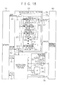
Fig. 18 is a block diagram showing the construction of a data processing system (processor) according to the 10th embodiment of the present invention for implementing an instruction break scheme by a hardware mechanism; -
Fig. 19 is a block diagram showing the construction of a determination section according to the 10th embodiment; -
Fig. 20 is a block diagram showing the construction of a data processing system (processor) according to the 11th embodiment of the present invention for implementing an instruction break scheme by a hardware mechanism; -
Fig. 21 is a block diagram showing the construction of a determination section according to the 11th embodiment; -
Fig. 22 is a block diagram showing the construction of a data processing system (processor) according to the 12th embodiment of the present invention for implementing an instruction break scheme by a hardware mechanism; -
Fig. 23 is a block diagram showing the construction of a determination section according to the 12th embodiment; -
Fig. 24 is a block diagram showing the construction of a data processing system (processor) according to the 13th embodiment of the present invention for implementing an instruction break scheme by a hardware mechanism; -
Fig. 25 is a block diagram showing the construction of a determination section according to the 13th embodiment; -
Fig. 26 is a block diagram showing the construction of a data processing system (processor) according to the 14th embodiment of the present invention for implementing an instruction break scheme by a hardware mechanism; -
Fig. 27 is a block diagram showing the construction of a determination section according to the 14th embodiment; -
Fig. 28 is a block diagram showing the construction of a data processing system (processor) according to the 15th embodiment of the present invention for implementing an instruction break scheme by a hardware mechanism; -
Fig. 29 is a block diagram showing the first construction of a determination section according to the 15th embodiment; -
Fig. 30 is a block diagram showing the second construction of the determination section according to the 15th embodiment; -
Fig. 31 is a block diagram showing the third construction of the determination section according to the 15th embodiment; -
Fig. 32 is a block diagram showing the fourth construction of the determination section according to the 15th embodiment; -
Fig. 33 is a block diagram showing the fifth construction of the determination section according to the 15th embodiment; -
Fig. 34 is a block diagram showing the construction of a data processing system (processor) according to the 16th embodiment of the present invention for implementing an instruction break scheme by a hardware mechanism; -
Fig. 35 is a block diagram showing the first construction of a determination section according to the 16th embodiment; -
Fig. 36 is a block diagram showing the second construction of the determination section according to the 16th embodiment; -
Fig. 37 is a block diagram showing the third construction of the determination section according to the 16th embodiment; -
Fig. 38 is a block diagram showing the fourth construction of the determination section according to the 16th embodiment; -
Fig. 39 is a block diagram showing the fifth construction of the determination section according to the 16th embodiment; -
Fig. 40 is a block diagram showing the construction of a data processing system (processor) according to the 17th embodiment of the present invention for implementing an instruction break scheme by a hardware mechanism; -
Fig. 41 is a block diagram showing the first construction of a determination section according to the 17th embodiment; -
Fig. 42 is a block diagram showing the second construction of the determination section according to the 17th embodiment; -
Fig. 43 is a block diagram showing the third construction of the determination section according to the 17th embodiment; -
Fig. 44 is a block diagram showing the fourth construction of the determination section according to the 17th embodiment; -
Fig. 45 is a block diagram showing the fifth construction of the determination section according to the 17th embodiment; -
Fig. 46 is a block diagram showing the construction of a determination section according to the 18th to 21st embodiments of the present invention; -
Fig. 47 is a flow chart showing the first example of processing by an instruction break-interrupt handler according to the 18th embodiment; -
Fig. 48 is a representation showing the first example of construction of a breakpoint table used in the 18th embodiment; -
Fig. 49 is a flow chart showing the second example of processing by the instruction break-interrupt handler according to the 18th embodiment; -
Fig. 50 is a flow chart showing the third example of processing by the instruction break-interrupt handler according to the 18th embodiment; -
Fig. 51 is a representation showing the second example of construction of the breakpoint table used in the 18th embodiment; -
Fig. 52 is a flow chart showing the fourth example of processing by the instruction break-interrupt handler according to the 18th embodiment; -
Fig. 53 is a flow chart showing the fifth example of processing by the instruction break-interrupt handler according to the 18th embodiment; -
Fig. 54 is a flow chart showing processing by an instruction break-interrupt handler according to the 19th embodiment; -
Fig. 55 is a representation showing the first example of construction of a breakpoint table used in the 19th embodiment; -
Fig. 56 is a representation showing the second example of construction of the breakpoint table used in the 19th embodiment; -
Fig. 57 is a flow chart showing processing by an instruction break-interrupt handler according to the 20th embodiment; -
Fig. 58 is a flow chart showing processing by an instruction break-interrupt handler according to the 21st embodiment; -
Fig. 59 is a representation showing the first example of construction of a breakpoint table used in the 22nd embodiment of the present invention; -
Fig. 60 is a representation showing the second example of construction of the breakpoint table used in the 22nd embodiment; and -
Fig. 61 is a representation showing the third example of construction of the breakpoint table used in the 22nd embodiment. -
Fig. 6 is a block diagram showing the construction of an interrupt control apparatus according to the first embodiment of the present invention. - Referring to
Fig. 6 ,reference numeral 410 denotes a memory which stores programs including an application and interrupt handler; 420 denotes an instruction fetch section; 430 denotes an instruction execution section; 440 denotes an interrupt control section; and 450 denotes a register section. - The instruction fetch
section 420 comprises an instruction fetchcontroller 421, aprogram counter 422, and aninstruction word register 423. The instruction fetchcontroller 421 reads out aninstruction word 472 from thememory 410 on the basis of aninstruction address 471 indicated by theprogram counter 422 and writes/holds the read-out instruction word in theinstruction register 423. The instruction fetchsection 420 also supplies aninstruction word 473 held in theinstruction register 423 to theinstruction execution section 430. - When an
instruction address 474 of a branch destination or an instruction address 475 for return from the interrupt state is supplied from theinstruction execution section 430, or when aninstruction address 476 of a normal interrupt handler or aninstruction address 477 of a break-interrupt handler is supplied from the interruptcontrol section 440, the instruction fetchsection 420 writes the supplied instruction address in theprogram counter 422. Otherwise, the value of theprogram counter 21 is incremented by one to read out the next instruction word sequentially. - When a break-interrupt by an instruction breakpoint or step execution is detected in reading out the
instruction word 472 from thememory 410, the instruction fetchcontroller 421 notifies the interruptcontrol section 440 of the break-interrupt using a break-interruptnotification signal 478. When a normal interrupt due to an instruction address conversion error or the like is detected, the instruction fetchcontroller 421 notifies the interruptcontrol section 440 of the normal interrupt using a normal interruptnotification signal 479. - The
instruction execution section 430 comprises aninstruction word decoder 431, aninstruction execution controller 432, abreakpoint controller 433, and an interruptreturn controller 434. Theinstruction word decoder 431 decodes theinstruction word 473 supplied from the instruction fetchsection 420. - If the supplied
instruction word 473 is an instruction word for generating a break-interrupt by a software breakpoint, a break-interrupt generation instruction is supplied to thebreakpoint controller 433. If the suppliedinstruction word 473 is an instruction word for returning the processor from the interrupt state, an interrupt return instruction is supplied to the interruptreturn controller 434. If the suppliedinstruction word 473 is an instruction word of another type, the decoded instruction is supplied to theinstruction execution controller 432. - The
instruction execution controller 432 executes processing such as calculation, branch, or data load/store in accordance with the instruction supplied from theinstruction word decoder 431. For example, if the supplied instruction is a calculation instruction, theinstruction execution controller 432 executes calculation on the basis of adata value 481 read out from a general-purpose register (GR) 451 in theregister section 450, which is designated by aregister address 480, and writes adata value 482 obtained by this calculation in the general-purpose register 451 designated by theregister address 480. - If the supplied instruction is a branch instruction, and the branch condition is satisfied, the
instruction execution controller 432 supplies theinstruction address 474 of the branch destination to the instruction fetchsection 420. If the supplied instruction is a load instruction or a store instruction, theinstruction execution controller 432 obtains the effective address on thememory 410 from thedata value 481 read out from the general-purpose register 451 designated by theregister address 480, and reads out readdata 483 or writes writedata 484 from/in an area of thememory 410, which corresponds to the effective address. - When detecting a break-interrupt by a data breakpoint, the
instruction execution controller 432 notifies the interruptcontrol section 440 of the break-interrupt using a break-interruptnotification signal 485. When a normal interrupt due to an error such as division by zero or data overflow is detected in executing a calculation instruction, theinstruction execution controller 432 notifies the interruptcontrol section 440 of the normal 1 interrupt using a normal interruptnotification signal 486. - In accordance with the break-interrupt generation instruction supplied from the
instruction word decoder 431, thebreakpoint controller 433 notifies the interruptcontrol section 440 of the break-interrupt using a break-interruptnotification signal 487. - The interrupt
return controller 434 executes a return operation from the interrupt state in accordance with the interrupt return instruction supplied from theinstruction word decoder 431. At this time, the interruptreturn controller 434 specifies, on the basis of pieces of operation information before the interrupt, which are held by registers in theregister section 450, whether the operation is a return operation from a normal interrupt state or break-interrupt state, and restores the operation information before the interrupt. - The interrupt
control section 440 comprises a normal interruptcontroller 441 and break-interruptcontroller 442. When receiving the normal interrupt notification signal 479 from the instruction fetchsection 420 or the normal interrupt notification signal 486 from theinstruction execution section 430, the normal interruptcontroller 441 controls the instruction fetchsection 420 andregister section 450 to execute a shift operation to the normal interrupt state. - When receiving the normal interrupt notification signal 479 or 486, the normal interrupt
controller 441 reads out aninstruction address 488 at the time of normal interrupt from the instruction fetchsection 420, supplies astart address 476 of the normal interrupt handler to the instruction fetchsection 420, and sets the address in theprogram counter 422. The normal interruptcontroller 441 also writes received pieces of information on the normal interrupt, e.g., pieces of information on the instruction address at the time of normal interrupt in registers in theregister section 450. - When receiving the break-interrupt notification signal 478 from the instruction fetch
section 420 or one of the break-interruptnotification signals instruction execution section 430, the break-interruptcontroller 442 controls the instruction fetchsection 420 andregister section 450 to execute a shift operation to the break-interrupt state. - When receiving the break-interrupt
notification signal controller 442 loads aninstruction address 489 at the time of break-interrupt from the instruction fetchsection 420, supplies thestart address 477 of the break-interrupt handler to the instruction fetchsection 420, and sets the address in theprogram counter 422. The break-interruptcontroller 442 also writes received pieces of information on the break-interrupt, e.g., pieces of information on the instruction address at the time of break-interrupt in registers in theregister section 450. - The
register section 450 includes the general-purpose register 451 for holding data to be used for calculation or the like by theinstruction execution section 430, and registers 452 to 457 for holding data to be used for interrupt control (to be described below). Theregisters 452 to 457 for interrupt control will be described below. - The normal return address register (EPCR) 452 holds the original instruction address (the
value 488 of theprogram counter 422 at the time of normal interrupt) to which the processor will return from the normal interrupt state. The normal previous state register (EPSR) 453 holds the processor state before the normal interrupt (normal user state or supervisor state). The normal factor register (ECR) 454 holds the factor of a normal interrupt. The values of theseregisters 452 to 454 are set at the time of normal interrupt. The normalreturn address register 452, normalprevious state register 453, andnormal factor register 454 constitute the first information holding section of the present invention. - The break return address register (BEPCR) 455 holds the original instruction address (the
value 489 of theprogram counter 422 at the time of break-interrupt) to which the processor will return from the break-interrupt state. The value of this register is set at the time of break-interrupt. This breakreturn address register 455 constitutes the second information holding section of the present invention. The instruction address set in the normal return address register 452 or breakreturn address register 455 is supplied to the instruction fetchsection 420 as the return address 475 in returning from the interrupt operation, and the address value is set in theprogram counter 422. - The flag register (BE) 456 represents whether a break-interrupt state is set. The value "0" indicates a non-break-interrupt state, and the value "1" indicates a break-interrupt state. The initial value of the
flag register 456 is "0". When a break-interrupt occurs, the value transits from "0" to "1". In returning from the break-interrupt state, the value transits from "1" to "0". Theflag register 456 constitutes the return operation specifying section of the present invention. - The present state register (PSR) 457 holds the current processor state.
-
Fig. 7 is a representation showing an example of state transition of the processor in the first embodiment. - Referring to
Fig. 7 ,reference numeral 201 denotes a user state (to be referred to as a normal state hereinafter) without a normal interrupt or a break-interrupt; 202 denotes a supervisor state (to be referred to as a normal interrupt state hereinafter) without any break-interrupt; and 203 and 204 denote supervisor states (to be referred to as a break-interrupt state hereinafter) having a break-interrupt. When the processor is processing a normal application, the processor state is thenormal state 201. - When a normal interrupt 211 occurs in the
normal state 201, the processor transits to the normal interruptstate 202. When a normal interruptreturn instruction 212 is executed in this normal interruptstate 202, the processor returns to thenormal state 201. When a break-interrupt 213 or 215 occurs in thenormal state 201 or normal interruptstate 202, the processor transits to the break-interruptstate state normal state 201 or normal interruptstate 202 as the state before the break-interrupt. -
Fig. 8 is a representation showing another example of state transition of the processor in the first embodiment. - Referring to
Fig. 8 ,reference numeral 250 denotes a normal state of the processor; 251, 252, and 253 denote normal interrupt states of the processor; and 254, 255, 256, and 257 denote break-interrupt states of the processor. When the processor is processing a normal application, the processor state is thenormal state 250. - When a normal interrupt 261 occurs in the
normal state 250, the processor transits to the normal interruptstate 251. When a normal interruptreturn instruction 262 is executed in the normal interruptstate 251, the processor returns to thenormal state 250. If another normal interrupt 265 occurs before execution of the normal interruptreturn instruction 262 in the normal interruptstate 251, the processor transits from the normal interruptstate 251 to the next normal interruptstate 252. When a normal interruptreturn instruction 266 is executed in this normal interruptstate 252, the processor returns to the previous normal interruptstate 251. - When a break-interrupt 263, 267, 269, or 271 occurs in the
normal state 250 or normal interruptstate state return instruction state normal state 250 or normal interruptstate - The operation of the interrupt control apparatus shown in
Fig. 6 will be described next by exemplifying the processor state transition shown inFig. 7 :normal state 201 → normal interruptstate 202 → break-interruptstate 204 → normal interruptstate 202 →normal state 201. - When the processor is in the
normal state 201, the instruction fetchcontroller 421 shown inFig. 6 reads out theinstruction word 472 from thememory 410 on the basis of theinstruction address 471 indicated by theprogram counter 422 and writes/holds the read-out instruction word in theinstruction register 423. The instruction fetchsection 420 also supplies theinstruction word 473 held in theinstruction register 423 to theinstruction word decoder 431. - The
instruction word decoder 431 decodes the receivedinstruction word 473 and supplies an instruction to theinstruction execution controller 432 or thebreakpoint controller 433 in accordance with the decoding result. Theinstruction execution controller 432 or thebreakpoint controller 433 executes processing in accordance with the received instruction. If the break-interrupt 213 or the normal interrupt 211 does not occur in thisnormal state 201, the processor repeats the above operation. - However, when the instruction fetch
controller 421 or theinstruction execution controller 432 detects the normal interrupt 211, the normal interruptcontroller 441 is notified of the normal interrupt by the normal interrupt notification signal 479 from the instruction fetchcontroller 421 or the normal interrupt notification signal 486 from theinstruction execution controller 432. When receiving the normal interrupt notification from the instruction fetchcontroller 421 or theinstruction execution controller 432, the normal interruptcontroller 441 controls the instruction fetchsection 420 and theregister section 450 to perform processing as follows. - First, the normal interrupt
controller 441 reads out the presently indicatedinstruction address value 488 from theprogram counter 422 and writes the read-outinstruction address value 488 in the normalreturn address register 452. The normal interruptcontroller 441 also reads out the processor state (normal state) before the normal interrupt from thepresent state register 457, writes the read-out processor state in the normalprevious state register 453, and also writes the factor of the normal interrupt in thenormal factor register 454. - Next, the normal interrupt
controller 441 writes, in thepresent state register 457, the processor state that has transited in accordance with the normal interrupt. The normal interruptcontroller 441 also supplies thestart address 476 of the interrupt handler corresponding to the normal interrupt to the instruction fetchsection 420 and sets the address value in theprogram counter 422. Note that theflag register 456 keeps the initial value "0". Through the above-described process, the processor transits from thenormal state 201 to the normal interruptstate 202. - The processor which has transited to the normal interrupt
state 202 reads out theinstruction word 472 of the interrupt handler to the instruction fetchcontroller 421 in accordance with thestart address 476 of the interrupt handler, which is set in theprogram counter 422, temporarily holds the read-out instruction word in theinstruction word register 423, and then supplies the instruction word to theinstruction word decoder 431. - The
instruction word decoder 431 decodes the receivedinstruction word 473 and supplies the instruction to one of theinstruction execution controller 432, thebreakpoint controller 433, and the interruptreturn controller 434 in accordance with the decoding result. The controller which has received the instruction executes processing in accordance with the received instruction. Unless the break-interrupt 215 occurs in the normal interruptstate 202, theinstruction execution section 430 repeats the operation of executing theinstruction word 473 sequentially supplied toward the final address of the interrupt handler. - However, when the instruction fetch
controller 421, theinstruction execution controller 432, or thebreakpoint controller 433 detects the break-interrupt 215 during this operation, the break-interruptcontroller 442 is notified of the break-interrupt by the break-interrupt notification signal 478 from the instruction fetchcontroller 421, the break-interrupt notification signal 485 from theinstruction execution controller 432, or the break-interrupt notification signal 487 from thebreakpoint controller 433. - When receiving the break-interrupt notification from the instruction fetch
controller 421, theinstruction execution controller 432, or thebreakpoint controller 433, the break-interruptcontroller 442 controls the instruction fetchsection 420 andregister section 450 to perform processing as follows. - First, the break-interrupt
controller 442 reads out the currently indicatedinstruction address value 489 from theprogram counter 422, writes the read-outinstruction address value 489 in the breakreturn address register 455, and also writes "1" in theflag register 456. - Next, the break-interrupt
controller 442 writes, in thepresent state register 457, the processor state that has transited in accordance with the break-interrupt. The break-interruptcontroller 442 also supplies thestart address 477 of the interrupt handler corresponding to the break-interrupt to the instruction fetchsection 420 and sets the address value in theprogram counter 422. Through the above-described process, the processor transits from the normal interruptstate 202 to the break-interruptstate 204. - The processor which has transited to the break-interrupt
state 204 reads out theinstruction word 472 of the interrupt handler to the instruction fetchcontroller 421 in accordance with thestart address 477 of the interrupt handler, which is set in theprogram counter 422, temporarily holds the read-out instruction word in theinstruction word register 423, and then supplies the read-outinstruction word 473 to theinstruction word decoder 431. - The
instruction word decoder 431 decodes the receivedinstruction word 473 and supplies the instruction to theinstruction execution controller 432 or the interruptreturn controller 434 in accordance with the decoding result. The controller which has received the instruction executes processing in accordance with the received instruction. Theinstruction execution section 430 repeats the operation of executing theinstruction word 473 sequentially supplied toward the final address of the interrupt handler. - When processing of the interrupt handler corresponding to the break-interrupt is ended, the processor executes the break-interrupt return instruction 216. At this time, the interrupt return instruction read out from the
memory 410 and supplied to theinstruction word decoder 431 by the instruction fetchsection 420 is decoded by theinstruction word decoder 431 and determined as an interrupt return instruction. In accordance with this determination, theinstruction word decoder 431 supplies the interrupt return instruction to the interruptreturn controller 434. - When receiving the interrupt return instruction, the interrupt
return controller 434 refers to theflag register 456 in theregister section 450 and determines whether theflag register 456 has the value "1" representing the break-interrupt state. If the value of theflag register 456 is "1", the interruptreturn controller 434 controls the instruction fetchsection 420 andregister section 450 to perform processing as follows. - First, the interrupt
return controller 434 writes "0" in theflag register 456. The interruptreturn controller 434 also reads out, from the breakreturn address register 455, the original instruction address 475 to which the processor will return from the break-interrupt state, supplies the instruction address to the instruction fetchsection 420, and sets the address value in theprogram counter 422. - On the basis of the
original instruction address 471 set in theprogram counter 422, the instruction fetchcontroller 421 reads out theinstruction word 472 of the interrupt handler corresponding to the normal interrupt from thememory 410, temporarily holds the instruction word in theinstruction word register 423, and then supplies the instruction word to theinstruction execution section 430. Thus, the processor returns from the break-interruptstate 204 to the normal interruptstate 202. Theinstruction execution section 430 executes the remaining parts of processing of the interrupt handler corresponding to the normal interrupt. - When processing of the interrupt handler corresponding to the normal interrupt is ended in the normal interrupt
state 202, the processor executes the normal interruptreturn instruction 212. At this time, the interrupt return instruction read out from thememory 410 and supplied to theinstruction word decoder 431 by the instruction fetchcontroller 421 is decoded by theinstruction word decoder 431 and determined as an interrupt return instruction. In accordance with this determination, theinstruction word decoder 431 supplies the interrupt return instruction to the interruptreturn controller 434. - When receiving the interrupt return instruction, the interrupt
return controller 434 refers to theflag register 456 in theregister section 450 and determines whether theflag register 456 has the value "1". In this case, theflag register 456 has the value "0" representing the non-break-interrupt state. Hence, the interruptreturn controller 434 controls the instruction fetchsection 420 andregister section 450 to perform processing as follows. - The interrupt
return controller 434 reads out the value of the normalprevious state register 453 and writes the value in thepresent state register 457. The interruptreturn controller 434 also reads out, from the normalreturn address register 452, the original instruction address 475 to which the processor will return from the normal interrupt state, supplies the instruction address to the instruction fetchsection 420, and sets the address value in theprogram counter 422. - On the basis of the
original instruction address 471 set in theprogram counter 422, the instruction fetchcontroller 421 reads out theinstruction word 472 for the normal operation from thememory 410, temporarily holds the instruction word in theinstruction word register 423, and then supplies the instruction word to theinstruction execution section 430. Thus, the processor transits from the normal interruptstate 202 to thenormal state 201. Theinstruction execution section 430 executes the remaining part of processing of the application corresponding to the normal operation. - As described above in detail, according to this embodiment, when a normal interrupt occurs, the processor operation information before the normal interrupt is saved by writing, in the normal
return address register 452, the original instruction address to which the processor will return from the normal interrupt state. When a break-interrupt occurs, the processor operation information before the break-interrupt is saved by writing, in the breakreturn address register 455, the original instruction address to which the processor will return from the break-interrupt state. In addition, whether a break-interrupt has occurred is set in theflag register 456. In returning from the interrupt, which one of addresses of the return address registers 452 and 455 is to be used is determined by referring to the value of theflag register 456. - According to this construction, even within the interrupt inhibition periods immediately after the interrupt operation by a normal interrupt and immediately before interrupt return, when a write in the normal
return address register 452, the normalprevious state register 453, and thenormal factor register 454 is inhibited, the break return address can be written in the break return address register 455 different from the normalreturn address register 452. Hence, a break-interrupt can occur even within the interrupt inhibition period by a normal interrupt. Additionally, the operation information before the normal interrupt or break-interrupt can be accurately restored by referring to the value of theflag register 456 in executing an interrupt return instruction. - The second embodiment of the present invention will be described next.
-
Fig. 9 is a block diagram showing the construction of an interrupt control apparatus according to the second embodiment. InFig. 9 , the same reference numerals as inFig. 6 denote the same blocks as inFig. 6 , respectively, and a detailed description thereof will be omitted. - In the second embodiment shown in
Fig. 9 , in addition toregisters 451 to 457 shown inFig. 6 , a break previous state register (BEPSR) 458 for holding the processor state before a break-interrupt is provided. - In this embodiment, the normal
return address register 452, the normalprevious state register 453, and thenormal factor register 454 constitute the first information holding section of the present invention, and the breakreturn address register 455 and the breakprevious state register 458 constitute the second information holding section of the present invention. - The
flag register 456 constitutes the return operation specifying section of the present invention. - The operation of the interrupt control apparatus shown in
Fig. 9 will be described next by exemplifying the processor state transition shown inFig. 7 :normal state 201 → normal interruptstate 202 → break-interruptstate 204 → normal interruptstate 202 →normal state 201. - When the processor in the
normal state 201 transits to the normal interruptstate 202 due to a normal interrupt, the same operation as that of the interrupt control apparatus shown inFig. 6 is performed. - When the processor is in the normal interrupt
state 202, and an instruction fetchcontroller 421, aninstruction execution controller 432, or an interruptreturn controller 434 detects a break-interrupt 215, a break-interruptcontroller 442 is notified of the break-interrupt by a break-interrupt notification signal 478 from the instruction fetchcontroller 421, a break-interrupt notification signal 485 from theinstruction execution controller 432, or a break-interrupt notification signal 487 from thebreakpoint controller 433. - When receiving the break-interrupt notification from the instruction fetch
controller 421, theinstruction execution controller 432, or thebreakpoint controller 433, the break-interruptcontroller 442 controls an instruction fetchsection 420 and aregister section 450 to perform processing as follows. - First, the break-interrupt
controller 442 reads out the currently indicatedinstruction address value 489 from aprogram counter 422, writes the read-outinstruction address value 489 in the breakreturn address register 455, and also writes "1" in theflag register 456. The break-interruptcontroller 442 also reads out the processor state (normal interrupt state) before the break-interrupt from thepresent state register 457 and writes the read-out processor state in the breakprevious state register 458. - Next, the break-interrupt
controller 442 writes, in thepresent state register 457, the processor state that has transited in accordance with the break-interrupt. The break-interruptcontroller 442 also supplies astart address 477 of the interrupt handler corresponding to the break-interrupt to the instruction fetchsection 420 and sets the address value in theprogram counter 422. By processing as described above, the processor transits from the normal interruptstate 202 to the break-interruptstate 204. - The processor which has transited to the break-interrupt
state 204 reads out aninstruction word 472 of the interrupt handler to the instruction fetchcontroller 421 in accordance with thestart address 477 of the interrupt handler, which is set in theprogram counter 422, temporarily holds the read-out instruction word in aninstruction word register 423, and then supplies the read-outinstruction word 473 to aninstruction word decoder 431. - The
instruction word decoder 431 decodes a receivedinstruction word 473 and supplies the instruction to theinstruction execution controller 432 or interruptreturn controller 434 in accordance with the decoding result. The controller which has received the instruction executes processing in accordance with the received instruction. Aninstruction execution section 430 repeats the operation of executing theinstruction word 473 sequentially supplied toward the final address of the interrupt handler. - When processing of the interrupt handler corresponding to the break-interrupt is ended, the processor executes a break-interrupt return instruction 216. At this time, the interrupt return instruction read out from a
memory 410 and supplied to theinstruction word decoder 431 by the instruction fetchsection 420 is decoded by theinstruction word decoder 431 and determined as an interrupt return instruction. In accordance with this determination, theinstruction word decoder 431 supplies the interrupt return instruction to the interruptreturn controller 434. - When receiving the interrupt return instruction, the interrupt
return controller 434 refers to theflag register 456 in theregister section 450 and determines whether theflag register 456 has the value "1" representing the break-interrupt state. If the value of theflag register 456 is "1", the interruptreturn controller 434 controls the instruction fetchsection 420 and theregister section 450 to perform processing as follows. - First, the interrupt
return controller 434 writes "0" in theflag register 456 and simultaneously reads out the value of the breakprevious state register 458 and writes the value in thepresent state register 457. The interruptreturn controller 434 also reads out, from the breakreturn address register 455, an original instruction address 475 to which the processor will return from the break-interrupt state, supplies the instruction address to the instruction fetchsection 420, and sets the address value in theprogram counter 422. - On the basis of an
original instruction address 471 set in theprogram counter 422, the instruction fetchcontroller 421 reads out theinstruction word 472 of the interrupt handler corresponding to the normal interrupt from thememory 410, temporarily holds the instruction word in theinstruction word register 423, and then supplies the instruction word to theinstruction execution section 430. Thus, the processor returns from the break-interruptstate 204 to the normal interruptstate 202. Theinstruction execution section 430 executes the remaining part of processing of the interrupt handler corresponding to the normal interrupt. - When processing of the interrupt handler corresponding to the normal interrupt is ended in the normal interrupt
state 202, the processor executes a normal interruptreturn instruction 212 and returns from the normal interruptstate 202 to thenormal state 201. The operation at this time is the same as that of the interrupt control apparatus shown inFig. 6 . - As described above, in the second embodiment, in addition to the operation of the above-described first embodiment, when a break-interrupt occurs, the processor state before the break-interrupt is written in the break
previous state register 458. - According to this construction, a break-interrupt can occur even within the interrupt inhibition period by a normal interrupt, and additionally, the processor state before the interrupt can be held even for the break-interrupt. In returning from the break-interrupt, the previous processor state can be easily restored only by referring to the value of one register.
- The third embodiment of the present invention will be described next.
-
Fig. 10 is a block diagram showing the construction of an interrupt control apparatus according to the third embodiment. InFig. 10 , the same reference numerals as inFig. 6 denote the same blocks as inFig. 6 , respectively, and a detailed description thereof will be omitted. - In the third embodiment shown in
Fig. 10 , in addition to theregisters 451 to 457 shown inFig. 6 , a break factor register (BECR) 459 for holding the factor (instruction breakpoint, data breakpoint, software breakpoint, or step execution) of a break-interrupt is provided. - In this embodiment, the normal
return address register 452, the normalprevious state register 453, and thenormal factor register 454 constitute the first information holding section of the present invention, and the breakreturn address register 455 and the break factor register 459 constitute the second information holding section of the present invention. - The
flag register 456 constitutes the return operation specifying section of the present invention. - The operation of the interrupt control apparatus shown in
Fig. 10 will be described next by exemplifying the processor state transition shown inFig. 7 :normal state 201 → normal interruptstate 202 → break-interruptstate 204 → normal interruptstate 202 →normal state 201. - When the processor in the
normal state 201 transits to the normal interruptstate 202 due to a normal interrupt, the same operation as that of the interrupt control apparatus shown inFig. 6 is performed. - When the processor is in the normal interrupt
state 202, and an instruction fetchcontroller 421, aninstruction execution controller 432, or an interruptreturn controller 434 detects a break-interrupt 215, a break-interruptcontroller 442 is notified of the break-interrupt by a break-interrupt notification signal 478 from the instruction fetchcontroller 421, a break-interrupt notification signal 485 from theinstruction execution controller 432, or a break-interrupt notification signal 487 from thebreakpoint controller 433. - When receiving the break-interrupt notification from the instruction fetch
controller 421, theinstruction execution controller 432, or thebreakpoint controller 433, the break-interruptcontroller 442 controls an instruction fetchsection 420 and theregister section 450 to perform processing as follows. - First, the break-interrupt
controller 442 reads out the currently indicatedinstruction address value 489 from aprogram counter 422, writes the read-outinstruction address value 489 in the breakreturn address register 455, and also writes "1" in theflag register 456. The break-interruptcontroller 442 also writes the factor of the break-interrupt in thebreak factor register 459. - Next, the break-interrupt
controller 442 writes, in thepresent state register 457, the processor state that has transited in accordance with the break-interrupt. The break-interruptcontroller 442 also supplies astart address 477 of the interrupt handler corresponding to the break-interrupt to the instruction fetchsection 420 and sets the address value in theprogram counter 422. By processing as described above, the processor transits from the normal interruptstate 202 to the break-interruptstate 204. - The processor which has transited to the break-interrupt
state 204 reads out aninstruction word 472 of the interrupt handler to the instruction fetchcontroller 421 in accordance with thestart address 477 of the interrupt handler, which is set in theprogram counter 422, temporarily holds the read-out instruction word in aninstruction word register 423, and then supplies the read-outinstruction word 473 to aninstruction word decoder 431. - The
instruction word decoder 431 decodes a receivedinstruction word 473 and supplies the instruction to theinstruction execution controller 432 or interruptreturn controller 434 in accordance with the decoding result. The controller which has received the instruction executes processing in accordance with the received instruction. Aninstruction execution section 430 repeats the operation of executing theinstruction word 473 sequentially supplied toward the final address of the interrupt handler. - When processing of the interrupt handler corresponding to the break-interrupt is ended, the processor executes a break-interrupt return instruction 216. At this time, the interrupt return instruction read out from a
memory 410 and supplied to theinstruction word decoder 431 by the instruction fetchsection 420 is decoded by theinstruction word decoder 431 and determined as an interrupt return instruction. In accordance with this determination, theinstruction word decoder 431 supplies the interrupt return instruction to the interruptreturn controller 434. - When receiving the interrupt return instruction, the interrupt
return controller 434 refers to theflag register 456 in theregister section 450 and determines whether theflag register 456 has the value "1" representing the break-interrupt state. If the value of theflag register 456 is "1", the interruptreturn controller 434 controls the instruction fetchsection 420 andregister section 450 to perform processing as follows. - First, the interrupt
return controller 434 writes "0" in theflag register 456. The interruptreturn controller 434 also reads out, from the breakreturn address register 455, an original instruction address 475 to which the processor will return from the break-interrupt state, supplies the instruction address to the instruction fetchsection 420, and sets the address value in theprogram counter 422. - On the basis of an
original instruction address 471 set in theprogram counter 422, the instruction fetchcontroller 421 reads out theinstruction word 472 of the interrupt handler corresponding to the normal interrupt from thememory 410, temporarily holds the instruction word in theinstruction word register 423, and then supplies the instruction word to theinstruction execution section 430. Thus, the processor returns from the break-interruptstate 204 to the normal interruptstate 202. Theinstruction execution section 430 executes the remaining part of processing of the interrupt handler corresponding to the normal interrupt. - When processing of the interrupt handler corresponding to the normal interrupt is ended in the normal interrupt
state 202, the processor executes a normal interruptreturn instruction 212 and returns from the normal interruptstate 202 to thenormal state 201. The operation at this time is the same as that of the interrupt control apparatus shown inFig. 6 . - As described above, in the third embodiment, in addition to the operation of the above-described first embodiment, when a break-interrupt occurs, the factor of the break-interrupt is written in the
break factor register 459. - According to this construction, a break-interrupt can occur even within the interrupt inhibition period by a normal interrupt, and additionally, the interrupt factor can be held even for the break-interrupt. For this reason, in a break-interrupt handler, not only predetermined specific processing but also appropriate interrupt processing corresponding to the interrupt factor can be performed.
- The fourth embodiment of the present invention will be described next.
-
Fig. 11 is a block diagram showing the construction of an interrupt control apparatus according to the fourth embodiment. InFig. 11 , the same reference numerals as inFigs. 6 ,9 , and10 denote the same blocks as inFigs. 6 ,9 , and10 , respectively, and a detailed description thereof will be omitted. - In the fourth embodiment shown in
Fig. 11 , in addition to theregisters 451 to 457 shown inFig. 6 , a breakprevious state register 458 and a break factor register 459 are provided. - In this embodiment, the normal
return address register 452, the normalprevious state register 453, and thenormal factor register 454 constitute the first information holding section of the present invention, and the breakreturn address register 455, the breakprevious state register 458, and the break factor register 459 constitute the second information holding section of the present invention. - The
flag register 456 constitutes the return operation specifying section of the present invention. - The operation of the interrupt control apparatus shown in
Fig. 11 will be described next by exemplifying the processor state transition shown inFig. 7 :normal state 201 → normal interruptstate 202 → break-interruptstate 204 → normal interruptstate 202 →normal state 201. - When the processor in the
normal state 201 transits to the normal interruptstate 202 due to a normal interrupt, the same operation as that of the interrupt control apparatus shown inFig. 6 is performed. - When the processor is in the normal interrupt
state 202, and an instruction fetchcontroller 421, aninstruction execution controller 432, or an interruptreturn controller 434 detects a break-interrupt 215, a break-interruptcontroller 442 is notified of the break-interrupt by a break-interrupt notification signal 478 from the instruction fetchcontroller 421, a break-interrupt notification signal 485 from theinstruction execution controller 432, or a break-interrupt notification signal 487 from thebreakpoint controller 433. - When receiving the break-interrupt notification from the instruction fetch
controller 421, theinstruction execution controller 432, or thebreakpoint controller 433, the break-interruptcontroller 442 controls an instruction fetchsection 420 and aregister section 450 to perform processing as follows. - First, the break-interrupt
controller 442 reads out the currently indicatedinstruction address value 489 from aprogram counter 422, writes the read-outinstruction address value 489 in the breakreturn address register 455, and also writes "1" in theflag register 456. The break-interruptcontroller 442 also reads out the processor state (normal interrupt state) before the break-interrupt from thepresent state register 457 and writes the read-out processor state in the breakprevious state register 458, and simultaneously writes the factor of the break-interrupt in thebreak factor register 459. - Next, the break-interrupt
controller 442 writes, in thepresent state register 457, the processor state that has transited in accordance with the break-interrupt. The break-interruptcontroller 442 also supplies astart address 477 of the interrupt handler corresponding to the break-interrupt to the instruction fetchsection 420 and sets the address value in theprogram counter 422. By processing as described above, the processor transits from the normal interruptstate 202 to the break-interruptstate 204. - The processor which has transited to the break-interrupt
state 204 reads out aninstruction word 472 of the interrupt handler to the instruction fetchcontroller 421 in accordance with thestart address 477 of the interrupt handler, which is set in theprogram counter 422, temporarily holds the read-out instruction word in aninstruction word register 423, and then supplies the read-outinstruction word 473 to aninstruction word decoder 431. Theinstruction word decoder 431 decodes a receivedinstruction word 473 and supplies the instruction to theinstruction execution controller 432 or the interruptreturn controller 434 in accordance with the decoding result. The controller which has received the instruction executes processing in accordance with the received instruction. Aninstruction execution section 430 repeats the operation of executing theinstruction word 473 sequentially supplied toward the final address of the interrupt handler. - When processing of the interrupt handler corresponding to the break-interrupt is ended, the processor executes a break-interrupt return instruction 216. At this time, the interrupt return instruction read out from a
memory 410 and supplied to theinstruction word decoder 431 by the instruction fetchsection 420 is decoded by theinstruction word decoder 431 and determined as an interrupt return instruction. In accordance with this determination, theinstruction word decoder 431 supplies the interrupt return instruction to the interruptreturn controller 434. - When receiving the interrupt return instruction, the interrupt
return controller 434 refers to theflag register 456 in theregister section 450 and determines whether theflag register 456 has the value "1" representing the break-interrupt state. If the value of theflag register 456 is "1", the interruptreturn controller 434 controls the instruction fetchsection 420 andregister section 450 to perform processing as follows. - First, the interrupt
return controller 434 writes "0" in theflag register 456 and simultaneously reads out the value of the breakprevious state register 458 and writes the value in thepresent state register 457. The interruptreturn controller 434 also reads out, from the breakreturn address register 455, an original instruction address 475 to which the processor will return from the break-interrupt state, supplies the instruction address to the instruction fetchsection 420, and sets the address value in theprogram counter 422. - On the basis of an
original instruction address 471 set in theprogram counter 422, the instruction fetchcontroller 421 reads out theinstruction word 472 of the interrupt handler corresponding to the normal interrupt from thememory 410, temporarily holds the instruction word in theinstruction word register 423, and then supplies the instruction word to theinstruction execution section 430. Thus, the processor returns from the break-interruptstate 204 to the normal interruptstate 202. Theinstruction execution section 430 executes the remaining part of processing of the interrupt handler corresponding to the normal interrupt. - When processing of the interrupt handler corresponding to the normal interrupt is ended in the normal interrupt
state 202, the processor executes a normal interruptreturn instruction 212 and returns from the normal interruptstate 202 to thenormal state 201. The operation at this time is the same as that of the interrupt control apparatus shown inFig. 6 . - As described above, in the fourth embodiment, in addition to the operation of the above-described first embodiment, when a break-interrupt occurs, the processor state before the break-interrupt is written in the break
previous state register 458, and the factor of the break-interrupt is written in thebreak factor register 459. - According to this construction, a break-interrupt can occur even within the interrupt inhibition period by a normal interrupt. In addition, even in a break-interrupt handler, the previous processor state can be easily restored only in returning from the break-interrupt, and appropriate interrupt processing corresponding to the break-interrupt factor can be performed.
- The fifth embodiment of the present invention will be described next.
-
Fig. 12 is a block diagram showing the construction of an interrupt control apparatus according to the fifth embodiment. InFig. 12 , the same reference numerals as inFig. 6 denote the same blocks as inFig. 6 , respectively, and a detailed description thereof will be omitted. - Referring to
Fig. 12 , an interrupt return controller 434' executes a return operation from an interrupt state, like the interruptreturn controller 434 shown inFig. 6 . The interrupt return controller 434' of this embodiment specifies whether the operation is a return operation from a normal interrupt state or a return operation from a break-interrupt state on the basis of information in the interrupt return instruction and restores operation information before the interrupt. - Additionally, in this embodiment, the
flag register 456 used in the first to fourth embodiments is omitted, and instead, an interrupt return instruction (to be described later) contains information on whether a break-interrupt state is set. - In this embodiment, a normal
return address register 452, a normalprevious state register 453, and anormal factor register 454 constitute the first information holding section of the present invention, and a breakreturn address register 455 constitutes the second information holding section of the present invention. -
Fig. 13 is a representation showing the instruction form of an interrupt return instruction according to this embodiment. - Referring to
Fig. 13 ,reference numeral 101 denotes a field representing an instruction code; and 102 denotes a field representing an operand. In this embodiment, theinstruction code 101 means an interrupt return instruction, and the value of theoperand 102 means whether a break-interrupt state is set. Theoperand 102 having the value "0" means return from a normal interrupt state, and the value "1" means return from a break-interrupt state. - The interrupt return instruction shown in
Fig. 13 is prepared at the end of each of an interrupt handler for a normal interrupt and an interrupt handler for a break-interrupt. The value of theoperand 102 of the interrupt return instruction for a normal interrupt is set to "0", and the value of theoperand 102 of the interrupt return instruction for a break-interrupt is set to "1". Theoperand 102 of the interrupt return instruction constitutes the return operation specifying section of the present invention. - The operation of the interrupt control apparatus shown in
Fig. 12 will be described next by exemplifying the processor state transition shown inFig. 7 :normal state 201 → normal interruptstate 202 → break-interruptstate 204 → normal interruptstate 202 →normal state 201. - When the processor in the
normal state 201 transits to the normal interruptstate 202 due to a normal interrupt, the same operation as that of the interrupt control apparatus shown inFig. 6 is performed. - When the processor is in the normal interrupt
state 202, and an instruction fetchcontroller 421, aninstruction execution controller 432, or an interruptreturn controller 434 detects a break-interrupt 215, a break-interruptcontroller 442 is notified of the break-interrupt by a break-interrupt notification signal 478 from the instruction fetchcontroller 421, a break-interrupt notification signal 485 from theinstruction execution controller 432, or a break-interrupt notification signal 487 from thebreakpoint controller 433. - When receiving the break-interrupt notification from the instruction fetch
controller 421, theinstruction execution controller 432, or thebreakpoint controller 433, the break-interruptcontroller 442 controls an instruction fetchsection 420 andregister section 450 to perform processing as follows. - First, the break-interrupt
controller 442 reads out the currently indicatedinstruction address value 489 from aprogram counter 422 and writes the read-outinstruction address value 489 in the breakreturn address register 455. - Next, the break-interrupt
controller 442 writes, in thepresent state register 457, the processor state that has transited in accordance with the break-interrupt. The break-interruptcontroller 442 also supplies astart address 477 of the interrupt handler corresponding to the break-interrupt to the instruction fetchsection 420 and sets the address value in theprogram counter 422. By processing as described above, the processor transits from the normal interruptstate 202 to the break-interruptstate 204. - The processor which has transited to the break-interrupt
state 204 reads out aninstruction word 472 of the interrupt handler to the instruction fetchcontroller 421 in accordance with thestart address 477 of the interrupt handler, which is set in theprogram counter 422, temporarily holds the read-out instruction word in aninstruction word register 423, and then supplies the read-outinstruction word 473 to aninstruction word decoder 431. - The
instruction word decoder 431 decodes a receivedinstruction word 473 and supplies the instruction to theinstruction execution controller 432 or the interrupt return controller 434' in accordance with the decoding result. The controller which has received the instruction executes processing in accordance with the received instruction. Aninstruction execution section 430 repeats the operation of executing theinstruction word 473 sequentially supplied toward the final address of the interrupt handler. - When processing of the interrupt handler corresponding to the break-interrupt is ended, the processor executes a break-interrupt return instruction 216. At this time, the interrupt return instruction read out from a
memory 410 and supplied to theinstruction word decoder 431 by the instruction fetchsection 420 is decoded by theinstruction word decoder 431 and determined as an interrupt return instruction. In accordance with this determination, theinstruction word decoder 431 supplies the interrupt return instruction to the interrupt return controller 434'. - When receiving the interrupt return instruction, the interrupt return controller 434' refers to the
operand 102 of the received interrupt return instruction and determines whether the value is "1". If theoperand 102 has the value "1" representing return from the break-interrupt state, the interrupt return controller 434' controls the instruction fetchsection 420 andregister section 450 to perform processing as follows. - First, the interrupt return controller 434' reads out, from the break
return address register 455, an original instruction address 475 to which the processor will return from the break-interrupt state, supplies the instruction address to the instruction fetchsection 420, and sets the address value in theprogram counter 422. - On the basis of an
original instruction address 471 set in theprogram counter 422, the instruction fetchcontroller 421 reads out theinstruction word 472 of the interrupt handler corresponding to the normal interrupt from thememory 410, temporarily holds the instruction word in theinstruction word register 423, and then supplies the instruction word to theinstruction execution section 430. Thus, the processor returns from the break-interruptstate 204 to the normal interruptstate 202. Theinstruction execution section 430 executes the remaining part of processing of the interrupt handler corresponding to the normal interrupt. - When processing of the interrupt handler corresponding to the normal interrupt is ended in the normal interrupt
state 202, the processor executes a normal interruptreturn instruction 212. At this time, the interrupt return instruction read out from thememory 410 and supplied to theinstruction word decoder 431 by the instruction fetchsection 420 is decoded by theinstruction word decoder 431 and determined as an interrupt return instruction. In accordance with this determination, theinstruction word decoder 431 supplies the interrupt return instruction to the interrupt return controller 434'. - When receiving the interrupt return instruction, the interrupt return controller 434' refers to the
operand 102 of the received interrupt return instruction and determines whether the value is "1". In this case, theoperand 102 has the value "0" representing return from the normal interrupt state. The interrupt return controller 434' controls the instruction fetchsection 420 and theregister section 450 to start the normal interrupt return operation. In this normal interrupt return operation, the same operation as that of the interrupt control apparatus shown inFig. 6 is performed, and the normal interruptstate 202 transits to thenormal state 201. - As described above, according to the fifth embodiment, when a normal interrupt occurs, the processor operation information before the normal interrupt is saved by writing, in the normal
return address register 452, the original instruction address to which the processor will return from the normal interrupt state. When a break-interrupt occurs, the processor operation information before the break-interrupt is saved by writing, in the breakreturn address register 455, the original instruction address to which the processor will return from the break-interrupt state. In addition, an interrupt return instruction whoseoperand 102 has the value "0" is prepared at the end of an interrupt handler corresponding to a normal interrupt, and an interrupt return instruction whoseoperand 102 has the value "1" is prepared at the end of an interrupt handler corresponding to a break-interrupt. In returning from the interrupt, the address to be used, i.e., the address in the return address register 452 or 455 is determined by referring to the value of theoperand 102. - According to this construction, even within the interrupt inhibition periods immediately after the interrupt operation by a normal interrupt and immediately before interrupt return, the break return address can be written in the break return address register 455 different from the normal
return address register 452. Hence, a break-interrupt can occur even within the interrupt inhibition period by a normal interrupt. Additionally, the operation information before the normal interrupt or break-interrupt can be accurately restored by referring to the value of theoperand 102 of an interrupt return instruction in executing the interrupt return instruction. Furthermore, since not a register but theoperand 102 in the interrupt return instruction has an identifier representing return from the normal interrupt state or return from the break-interrupt state, the processor operation information before the interrupt can be restored with a minimum hardware resource. - The sixth embodiment of the present invention will be described next.
-
Fig. 14 is a block diagram showing the construction of an interrupt control apparatus according to the sixth embodiment. InFig. 14 , the same reference numerals as inFigs. 6 ,9 , and12 denote the same blocks as inFigs. 6 ,9 , and12 , respectively, and a detailed description thereof will be omitted. - In this embodiment, an interrupt return instruction shown in
Fig. 13 contains information on whether a break-interrupt state is set, like in the fifth embodiment shown inFig. 12 . - In this embodiment, a normal
return address register 452, a normalprevious state register 453, and anormal factor register 454 constitute the first information holding section of the present invention, and a breakreturn address register 455 and a breakprevious state register 458 constitute the second information holding section of the present invention. - The interrupt return instruction is prepared at the end of either of an interrupt handler for a normal interrupt and an interrupt handler for a break-interrupt. The value of an
operand 102 of the interrupt return instruction for a normal interrupt is set to "0", and the value of theoperand 102 of the interrupt return instruction for a break-interrupt is set to "1". Theoperand 102 of the interrupt return instruction constitutes the return operation specifying section of the present invention. - The operation of the interrupt control apparatus shown in
Fig. 14 will be described next by exemplifying the processor state transition shown inFig. 7 :normal state 201 → normal interruptstate 202 → break-interruptstate 204 → normal interruptstate 202 →normal state 201. - When the processor in the
normal state 201 transits to the normal interruptstate 202 due to a normal interrupt, the same operation as that of the interrupt control apparatus shown inFig. 6 is performed. - When the processor is in the normal interrupt
state 202, and an instruction fetchcontroller 421, aninstruction execution controller 432, or an interruptreturn controller 434 detects a break-interrupt 215, a break-interruptcontroller 442 is notified of the break-interrupt by a break-interrupt notification signal 478 from the instruction fetchcontroller 421, a break-interrupt notification signal 485 from theinstruction execution controller 432, or a break-interrupt notification signal 487 from thebreakpoint controller 433. - When receiving the break-interrupt notification from the instruction fetch
controller 421, theinstruction execution controller 432, or thebreakpoint controller 433, the break-interruptcontroller 442 controls an instruction fetchsection 420 andregister section 450 to perform processing as follows. - First, the break-interrupt
controller 442 reads out the currently indicatedinstruction address value 489 from aprogram counter 422 and writes the read-outinstruction address value 489 in the breakreturn address register 455. The break-interruptcontroller 442 also reads out the processor state (normal interrupt state) before the break-interrupt from thepresent state register 457 and writes the read-out processor state in the breakprevious state register 458. - Next, the break-interrupt
controller 442 writes, in thepresent state register 457, the processor state that has transited in accordance with the break-interrupt. The break-interruptcontroller 442 also supplies astart address 477 of the interrupt handler corresponding to the break-interrupt to the instruction fetchsection 420 and sets the address value in theprogram counter 422. By processing as described above, the processor transits from the normal interruptstate 202 to the break-interruptstate 204. - The processor which has transited to the break-interrupt
state 204 reads out aninstruction word 472 of the interrupt handler to the instruction fetchcontroller 421 in accordance with thestart address 477 of the interrupt handler, which is set in theprogram counter 422, temporarily holds the read-out instruction word in aninstruction word register 423, and then supplies the read-outinstruction word 473 to aninstruction word decoder 431. Theinstruction word decoder 431 decodes a receivedinstruction word 473 and supplies the instruction to theinstruction execution controller 432 or interrupt return controller 434' in accordance with the decoding result. The controller which has received the instruction executes processing in accordance with the received instruction. Aninstruction execution section 430 repeats the operation of executing theinstruction word 473 sequentially supplied toward the final address of the interrupt handler. - When processing of the interrupt handler corresponding to the break-interrupt is ended, the processor executes a break-interrupt return instruction 216. At this time, the interrupt return instruction read out from a
memory 410 and supplied to theinstruction word decoder 431 by the instruction fetchsection 420 is decoded by theinstruction word decoder 431 and determined as an interrupt return instruction. In accordance with this determination, theinstruction word decoder 431 supplies the interrupt return instruction to the interrupt return controller 434'. - When receiving the interrupt return instruction, the interrupt return controller 434' refers to the
operand 102 of the received interrupt return instruction and determines whether the value is "1". If theoperand 102 has the value "1" representing return from the break-interrupt state, the interrupt return controller 434' controls the instruction fetchsection 420 andregister section 450 to perform processing as follows. - First, the interrupt return controller 434' reads out the value of the break
previous state register 458 and writes the value in thepresent state register 457. The interrupt return controller 434' also reads out, from the breakreturn address register 455, an original instruction address 475 to which the processor will return from the break-interrupt state, supplies the instruction address to the instruction fetchsection 420, and sets the address value in theprogram counter 422. - On the basis of an
original instruction address 471 set in theprogram counter 422, the instruction fetchcontroller 421 reads out theinstruction word 472 of the interrupt handler corresponding to the normal interrupt from thememory 410, temporarily holds the instruction word in theinstruction word register 423, and then supplies the instruction word to theinstruction execution section 430. Thus, the processor returns from the break-interruptstate 204 to the normal interruptstate 202. Theinstruction execution section 430 executes the remaining part of processing of the interrupt handler corresponding to the normal interrupt. - When processing of the interrupt handler corresponding to the normal interrupt is ended in the normal interrupt
state 202, the processor executes a normal interruptreturn instruction 212 and returns from the normal interruptstate 202 to thenormal state 201. The operation at this time is the same as that of the interrupt control apparatus shown inFig. 12 . - As described above, in the sixth embodiment, in addition to the operation of the above-described fifth embodiment, when a break-interrupt occurs, the processor state before the break-interrupt is written in the break
previous state register 458. - According to this construction, a break-interrupt can occur even within the interrupt inhibition period by a normal interrupt, and additionally, the processor state before the interrupt can be held even for the break-interrupt. In returning from the break-interrupt, the previous processor state can be easily restored.
- The seventh embodiment of the present invention will be described next.
-
Fig. 15 is a block diagram showing the construction of an interrupt control apparatus according to the seventh embodiment. InFig. 15 , the same reference numerals as inFigs. 6 ,10 , and12 denote the same blocks as inFigs. 6 ,10 , and12 , respectively, and a detailed description thereof will be omitted. - In this embodiment, an interrupt return instruction shown in
Fig. 13 contains information on whether a break-interrupt state is set, like in the fifth embodiment shown inFig. 12 . - In this embodiment, a normal
return address register 452, a normalprevious state register 453, and anormal factor register 454 constitute the first information holding section of the present invention, and a breakreturn address register 455 and a break factor register 459 constitute the second information holding section of the present invention. - The interrupt return instruction is prepared at the end of either of an interrupt handler for a normal interrupt and an interrupt handler for a break-interrupt. The value of an
operand 102 of the interrupt return instruction for a normal interrupt is set to "0", and the value of theoperand 102 of the interrupt return instruction for a break-interrupt is set to "1". Theoperand 102 of the interrupt return instruction constitutes the return operation specifying section of the present invention. - The operation of the interrupt control apparatus shown in
Fig. 15 will be described next by exemplifying the processor state transition shown inFig. 7 :normal state 201 → normal interruptstate 202 → break-interruptstate 204 → normal interruptstate 202 →normal state 201. - When the processor in the
normal state 201 transits to the normal interruptstate 202 due to a normal interrupt, the same operation as that of the interrupt control apparatus shown inFig. 6 is performed. - When the processor is in the normal interrupt
state 202, and an instruction fetchcontroller 421, aninstruction execution controller 432, or an interruptreturn controller 434 detects a break-interrupt 215, a break-interruptcontroller 442 is notified of the break-interrupt by a break-interrupt notification signal 478 from the instruction fetchcontroller 421, a break-interrupt notification signal 485 from theinstruction execution controller 432, or a break-interrupt notification signal 487 from thebreakpoint controller 433. - When receiving the break-interrupt notification from the instruction fetch
controller 421, theinstruction execution controller 432, or thebreakpoint controller 433, the break-interruptcontroller 442 controls an instruction fetchsection 420 andregister section 450 to perform processing as follows. - First, the break-interrupt
controller 442 reads out the currently indicatedinstruction address value 489 from aprogram counter 422 and writes the read-outinstruction address value 489 in the breakreturn address register 455. The break-interruptcontroller 442 also writes the factor of the break-interrupt in thebreak factor register 459. - Next, the break-interrupt
controller 442 writes, in thepresent state register 457, the processor state that has transited in accordance with the break-interrupt. The break-interruptcontroller 442 also supplies astart address 477 of the interrupt handler corresponding to the break-interrupt to the instruction fetchsection 420 and sets the address value in theprogram counter 422. By processing as described above, the processor transits from the normal interruptstate 202 to the break-interruptstate 204. - The processor which has transited to the break-interrupt
state 204 reads out aninstruction word 472 of the interrupt handler to the instruction fetchcontroller 421 in accordance with thestart address 477 of the interrupt handler, which is set in theprogram counter 422, temporarily holds the read-out instruction word in aninstruction word register 423, and then supplies the read-outinstruction word 473 to aninstruction word decoder 431. Theinstruction word decoder 431 decodes a receivedinstruction word 473 and supplies the instruction to theinstruction execution controller 432 or the interrupt return controller 434' in accordance with the decoding result. The controller which has received the instruction executes processing in accordance with the received instruction. Aninstruction execution section 430 repeats the operation of executing theinstruction word 473 sequentially supplied toward the final address of the interrupt handler. - When processing of the interrupt handler corresponding to the break-interrupt is ended, the processor executes a break-interrupt return instruction 216. At this time, the interrupt return instruction read out from a
memory 410 and supplied to theinstruction word decoder 431 by the instruction fetchsection 420 is decoded by theinstruction word decoder 431 and determined as an interrupt return instruction. In accordance with this determination, theinstruction word decoder 431 supplies the interrupt return instruction to the interrupt return controller 434'. - When receiving the interrupt return instruction, the interrupt return controller 434' refers to the
operand 102 of the received interrupt return instruction and determines whether the value is "1". If theoperand 102 has the value "1" representing return from the break-interrupt state, the interrupt return controller 434' controls the instruction fetchsection 420 andregister section 450 to perform processing as follows. - First, the interrupt return controller 434' reads out, from the break
return address register 455, an original instruction address 475 to which the processor will return from the break-interrupt state, supplies the instruction address to the instruction fetchsection 420, and sets the address value in theprogram counter 422. On the basis of anoriginal instruction address 471 set in theprogram counter 422, the instruction fetchcontroller 421 reads out theinstruction word 472 of the interrupt handler corresponding to the normal interrupt from thememory 410, temporarily holds the instruction word in theinstruction word register 423, and then supplies the instruction word to theinstruction execution section 430. Thus, the processor returns from the break-interruptstate 204 to the normal interruptstate 202. Theinstruction execution section 430 executes the remaining part of processing of the interrupt handler corresponding to the normal interrupt. - When processing of the interrupt handler corresponding to the normal interrupt is ended in the normal interrupt
state 202, the processor executes a normal interruptreturn instruction 212 and returns from the normal interruptstate 202 to thenormal state 201. The operation at this time is the same as that of the interrupt control apparatus shown inFig. 12 . - As described above, in the seventh embodiment, in addition to the operation of the above-described fifth embodiment, when a break-interrupt occurs, the factor of the break-interrupt is written in the
break factor register 459. - According to this construction, a break-interrupt can occur even within the interrupt inhibition period by a normal interrupt, and additionally, the interrupt factor can be held even for the break-interrupt. For this reason, in a break-interrupt handler, not only predetermined specific processing but also appropriate interrupt processing corresponding to the interrupt factor can be performed.
- The eighth embodiment of the present invention will be described next.
-
Fig. 16 is a block diagram showing the construction of an interrupt control apparatus according to the eighth embodiment. InFig. 16 , the same reference numerals as inFigs. 6 ,9 ,10 , and12 denote the same blocks as inFigs. 6 ,9 ,10 , and12 , respectively, and a detailed description thereof will be omitted. - In this embodiment, an interrupt return instruction shown in
Fig. 13 contains information on whether a break-interrupt state is set, like in the fifth embodiment shown inFig. 12 . - In this embodiment, a normal
return address register 452, a normalprevious state register 453, and anormal factor register 454 constitute the first information holding section of the present invention, and a breakreturn address register 455, a breakprevious state register 458, and a break factor register 459 constitute the second information holding section of the present invention. - The interrupt return instruction is prepared at the end of either of an interrupt handler for a normal interrupt and an interrupt handler for a break-interrupt. The value of an
operand 102 of the interrupt return instruction for a normal interrupt is set to "0", and the value of theoperand 102 of the interrupt return instruction for a break-interrupt is set to "1". Theoperand 102 of the interrupt return instruction constitutes the return operation specifying section of the present invention. - The operation of the interrupt control apparatus shown in
Fig. 16 will be described next by exemplifying the processor state transition shown inFig. 7 :normal state 201 → normal interruptstate 202 → break-interruptstate 204 → normal interruptstate 202 →normal state 201. - When the processor in the
normal state 201 transits to the normal interruptstate 202 due to a normal interrupt, the same operation as that of the interrupt control apparatus shown inFig. 6 is performed. - When the processor is in the normal interrupt
state 202, and an instruction fetchcontroller 421, aninstruction execution controller 432, or an interruptreturn controller 434 detects a break-interrupt 215, a break-interruptcontroller 442 is notified of the break-interrupt by a break-interrupt notification signal 478 from the instruction fetchcontroller 421, a break-interrupt notification signal 485 from theinstruction execution controller 432, or a break-interrupt notification signal 487 from thebreakpoint controller 433. - When receiving the break-interrupt notification from the instruction fetch
controller 421, theinstruction execution controller 432, or thebreakpoint controller 433, the break-interruptcontroller 442 controls an instruction fetchsection 420 and aregister section 450 to perform processing as follows. - First, the break-interrupt
controller 442 reads out the currently indicatedinstruction address value 489 from aprogram counter 422 and writes the read-outinstruction address value 489 in the breakreturn address register 455. The break-interruptcontroller 442 also reads out the processor state (normal interrupt state) before the break-interrupt from thepresent state register 457 and writes the read-out processor state in the breakprevious state register 458. The break-interruptcontroller 442 also writes the factor of the break-interrupt in thebreak factor register 459. - Next, the break-interrupt
controller 442 writes, in thepresent state register 457, the processor state that has transited in accordance with the break-interrupt. The break-interruptcontroller 442 also supplies astart address 477 of the interrupt handler corresponding to the break-interrupt to the instruction fetchsection 420 and sets the address value in theprogram counter 422. By processing as described above, the processor transits from the normal interruptstate 202 to the break-interruptstate 204. - The processor which has transited to the break-interrupt
state 204 reads out aninstruction word 472 of the interrupt handler to the instruction fetchcontroller 421 in accordance with thestart address 477 of the interrupt handler, which is set in theprogram counter 422, temporarily holds the read-out instruction word in aninstruction word register 423, and then supplies the read-outinstruction word 473 to aninstruction word decoder 431. - The
instruction word decoder 431 decodes a receivedinstruction word 473 and supplies the instruction to theinstruction execution controller 432 or the interrupt return controller 434' in accordance with the decoding result. The controller which has received the instruction executes processing in accordance with the received instruction. Aninstruction execution section 430 repeats the operation of executing theinstruction word 473 sequentially supplied toward the final address of the interrupt handler. - When processing of the interrupt handler corresponding to the break-interrupt is ended, the processor executes a break-interrupt return instruction 216. At this time, the interrupt return instruction read out from a
memory 410 and supplied to theinstruction word decoder 431 by the instruction fetchsection 420 is decoded by theinstruction word decoder 431 and determined as an interrupt return instruction. In accordance with this determination, theinstruction word decoder 431 supplies the interrupt return instruction to the interrupt return controller 434'. - When receiving the interrupt return instruction, the interrupt return controller 434' refers to the
operand 102 of the received interrupt return instruction and determines whether the value is "1". If theoperand 102 has the value "1" representing return from the break-interrupt state, the interrupt return controller 434' controls the instruction fetchsection 420 and theregister section 450 to perform processing as follows. - First, the interrupt return controller 434' reads out the value of the break
previous state register 458 and writes the value in thepresent state register 457. The interrupt return controller 434' also reads out, from the breakreturn address register 455, an original instruction address 475 to which the processor will return from the break-interrupt state, supplies the instruction address to the instruction fetchsection 420, and sets the address value in theprogram counter 422. - On the basis of an
original instruction address 471 set in theprogram counter 422, the instruction fetchcontroller 421 reads out theinstruction word 472 of the interrupt handler corresponding to the normal interrupt from thememory 410, temporarily holds the instruction word in theinstruction word register 423, and then supplies the instruction word to theinstruction execution section 430. Thus, the processor returns from the break-interruptstate 204 to the normal interruptstate 202. Theinstruction execution section 430 executes the remaining part of processing of the interrupt handler corresponding to the normal interrupt. - When processing of the interrupt handler corresponding to the normal interrupt is ended in the normal interrupt
state 202, the processor executes a normal interruptreturn instruction 212 and returns from the normal interruptstate 202 to thenormal state 201. The operation at this time is the same as that of the interrupt control apparatus shown inFig. 12 . - As described above, in the eighth embodiment, in addition to the operation of the above-described fifth embodiment, when a break-interrupt occurs, the processor state before the break-interrupt is written in the break
previous state register 458, and the factor of the break-interrupt is written in thebreak factor register 459. - According to this construction, a break-interrupt can occur even within the interrupt inhibition period by a normal interrupt. In addition, even in a break-interrupt handler, the previous processor state can be easily restored only in returning from the break-interrupt, and appropriate interrupt processing corresponding to the break-interrupt factor can be performed.
- The ninth embodiment of the present invention will be described next.
-
Fig. 17 is a block diagram showing the construction of an interrupt control apparatus according to the ninth embodiment. InFig. 17 , the same reference numerals as inFig. 12 denote the same blocks as inFig. 12 , respectively, and a detailed description thereof will be omitted. - Referring to
Fig. 17 , reference numeral 341' denotes an instruction word decoder; 435 denotes a normal interrupt return controller; and 436 denotes a break-interrupt return controller. - The instruction word decoder 431' decodes an
instruction word 473 supplied from an instruction fetchsection 420, like theinstruction word decoder 431 shown inFig. 12 . When it is detected by decoding that the suppliedinstruction word 473 is an instruction word for generating a break-interrupt by a software breakpoint, the instruction word decoder 431' of this embodiment supplies a break-interrupt generation instruction to abreakpoint controller 433. - When the supplied
instruction word 473 is an instruction word for returning the processor from a normal interrupt state, the instruction word decoder 431' supplies a normal interrupt return instruction to the normal interruptreturn controller 435. When the suppliedinstruction word 473 is an instruction word for returning the processor from a break-interrupt state, the instruction word decoder 431' supplies a break-interrupt return instruction to the break-interruptreturn controller 436. When the suppliedinstruction word 473 is an instruction word of another type, the instruction word decoder 431' supplies the decoded instruction to aninstruction execution controller 432. - The normal interrupt
return controller 435 executes a return operation from the normal interrupt state in accordance with the normal interrupt return instruction supplied from the instruction word decoder 431'. The break-interruptreturn controller 436 executes a return operation from the break-interrupt state in accordance with the break-interrupt return instruction supplied from the instruction word decoder 431'. - More specifically, in the fifth embodiment shown in
Fig. 12 , it is specified in accordance with the value of theoperand 102 in the interrupt return instruction shown inFig. 13 whether the operation is a return operation from a normal interrupt state or break-interrupt state. In the ninth embodiment, however, as the contents of aninstruction code 101, two types of return instructions, a return instruction from a normal interrupt state and a return instruction from a break-interrupt state are used. In accordance with which return instruction is supplied to the instruction word decoder 431', the interrupt return controller which should perform the return operation is specified, and the processor operation information before the interrupt is restored. In this case, anoperand 102 has an arbitrary value. - In this embodiment, a normal
return address register 452, a normalprevious state register 453, and anormal factor register 454 constitute the first information holding section of the present invention, and a breakreturn address register 455 constitutes the second information holding section of the present invention. - In this embodiment as well, the interrupt return instruction is prepared at the end of each of an interrupt handler for a normal interrupt and an interrupt handler for a break-interrupt. The
instruction code 101 of an interrupt return instruction for a normal interrupt is constructed by a return instruction from a normal interrupt, and theinstruction code 101 of an interrupt return instruction for a break-interrupt is constructed by a return instruction from a break-interrupt. The two types of interrupt return instructions constitute the return operation specifying section of the present invention. - The operation of the interrupt control apparatus of this embodiment will be described next by exemplifying the processor state transition shown in
Fig. 7 :normal state 201 → normal interruptstate 202 → break-interruptstate 204 → normal interruptstate 202 →normal state 201. - In this embodiment, when the processor transits to an interrupt state due to a normal interrupt or break-interrupt, the same operation as that of the interrupt control apparatus shown in
Fig. 12 is performed. - Hence, only the return operation from a normal interrupt state and break-interrupt state, i.e., state transition: break-interrupt
state 204 → normal interruptstate 202 →normal state 201 will be described below. - When the processor is in the break-interrupt
state 204, and processing by an interrupt handler corresponding to the break-interrupt is ended, the processor executes an interrupt return instruction 216 at the end of the interrupt handler. Theinstruction code 101 of the interrupt return instruction executed at this time means an interrupt return instruction from the break-interrupt state. For this reason, the instruction word decoder 431' decodes the interrupt return instruction and consequently supplies a break-interrupt return instruction to the break-interruptreturn controller 436. When receiving the break-interrupt return instruction, the break-interruptreturn controller 436 controls the instruction fetchsection 420 and theregister section 450 to perform processing as follows. - First, the break-interrupt
return controller 436 reads out, from the breakreturn address register 455, an original instruction address 475 to which the processor will return from the break-interrupt state, supplies the instruction address to the instruction fetchsection 420, and sets the address value in aprogram counter 422. - On the basis of an
original instruction address 471 set in theprogram counter 422, an instruction fetchcontroller 421 reads out aninstruction word 472 of the interrupt handler corresponding to the normal interrupt from amemory 410, temporarily holds the instruction word in aninstruction word register 423, and then supplies the instruction word to aninstruction execution section 430. Thus, the processor returns from the break-interruptstate 204 to the normal interruptstate 202. Theinstruction execution section 430 executes the remaining part of processing of the interrupt handler corresponding to the normal interrupt. - When processing of the interrupt handler corresponding to the normal interrupt is ended in the normal interrupt
state 202, the processor executes an interruptreturn instruction 212 at the end of the interrupt handler. Theinstruction code 101 of the interrupt return instruction executed at this time means an interrupt return instruction from the normal interrupt state. For this reason, the instruction word decoder 431' decodes the interrupt return instruction and consequently supplies a normal interrupt return instruction to the normal interruptreturn controller 435. - When receiving the normal interrupt return instruction, the normal interrupt
return controller 435 controls the instruction fetchsection 420 andregister section 450 to start the normal interrupt return operation. For this normal interrupt return operation, the same operation as that of the interrupt control apparatus shown inFig. 12 is performed, and the normal interruptstate 202 transits to thenormal state 201. - As described above, in the ninth embodiment, a normal interrupt return instruction whose
instruction code 101 means a return instruction from a normal interrupt state is prepared at the end of an interrupt handler corresponding to a normal interrupt, and a break-interrupt return instruction whoseinstruction code 101 means a return instruction from a break-interrupt state is prepared at the end of an interrupt handler corresponding to a break-interrupt. In returning from an interrupt, the return operation is specified in accordance with the contents of theinstruction code 101. - According to this construction, even within the interrupt inhibition period immediately after interrupt processing by a normal interrupt and immediately before interrupt return, a break-interrupt can occur. In addition, the processor operation information before the interrupt can be restored with a minimum hardware resource. Furthermore, using two types of instructions: a return instruction from a normal interrupt state and a return instruction from a break-interrupt state, a return instruction for an interrupt can be executed, the calculation time can be shortened, and even when a break-interrupt occurs in a normal interrupt state, the processor operation information before the break-interrupt can be quickly and accurately restored.
- In the ninth embodiment, only the break
return address register 455 is provided as the second information holding section of the present invention. However, not only the break return address register 455 but also one or both of a breakprevious state register 458 and a break factor register 459 may be provided, like in the sixth to eighth embodiments shown inFigs. 14 to 16 . - In this case, when the processor transits to an interrupt state due to a normal interrupt or break-interrupt, the same operation as that of the interrupt control apparatuses shown in
Figs. 14 to 16 is performed. As for the return operation from the interrupt state, the return operation from a normal interrupt state is executed by the normal interruptreturn controller 435, and the return operation from a break-interrupt state is executed by the break-interruptreturn controller 436. Control of the registers is the same as that in the interrupt control apparatuses shown inFigs. 14 to 16 . - The above embodiments can be applied to debug an interrupt handler corresponding to exceptional processing or external interrupt, and also to debug an interrupt handler corresponding to system call or supervisor call of an OS (Operating System).
- The 10th embodiment of the present invention will be described below with reference to drawings.
-
Fig. 18 is a block diagram showing the construction of a data processing system (processor) according to the 10th embodiment for implementing an instruction break scheme by a hardware mechanism. - In
Fig. 18 , the same reference numerals as inFig. 3 denote the same functional parts as inFig. 3 , respectively, and a detailed description thereof will be omitted. - In the 10th embodiment, an instruction
break detection section 23 has, in place of thedetermination sections 25-0 to 25-n used inFig. 3 ,determination sections 100-0 to 100-n for performing determination processing different from that of thedetermination sections 25-0 to 25-n. - These
determination sections 100-0 to 100-n receive not only instruction break addresses and flags held in breakpoint registers 24-0 to 24-n prepared in units ofdetermination sections 100-0 to 100-n and current execution address supplied from aprogram counter 21 but also the condition code of a conditional instruction, which is read out from acondition register 51 in aregister section 50, and an instruction word that is read out from aninstruction register 22 and currently being executed. -
Fig. 19 is a block diagram showing the construction of thedetermination section 100-0 as a representative of thedetermination sections 100-0 to 100-n. Each of the remainingdetermination sections 100-1 to 100-n has the same construction as inFig. 19 . - As shown in
Fig. 19 , thedetermination section 100-0 of this embodiment comprises acomparison section 101, aconditional instruction decoder 102, acondition determination section 103, and an ANDcircuit 104. - The
comparison section 101 compares an instruction break address held in anaddress register 24a of the breakpoint register 24-0 provided in accordance with thedetermination section 100-0 with a current execution address supplied from theprogram counter 21 and determines whether the two addresses match. When the two addresses match, thecomparison section 101 outputs a determination signal having the value "1". When the two addresses do not match, thecomparison section 101 outputs a determination signal having the value "0". - The
conditional instruction decoder 102 decodes the instruction word that is supplied from theinstruction register 22 and currently being executed to detect whether the instruction is a conditional instruction, and supplies the detection result to thecondition determination section 103. On the basis of the decoding result of the instruction word, which is supplied from theconditional instruction decoder 102, thecondition determination section 103 determines whether the condition designated by the condition code of the conditional instruction, which is supplied from thecondition register 51, is satisfied. If the condition designated by the condition code of the conditional instruction is satisfied, a determination signal having the value "1" is output. If the condition is not satisfied, a determination signal having the value "0" is output. If it is found by decoding by theconditional instruction decoder 102 that the supplied instruction is not a conditional instruction, thecondition determination section 103 outputs a determination signal having the value "0". - The AND
circuit 104 performs AND operation to the value of aflag register 24b of the breakpoint register 24-0 provided in accordance with thedetermination section 100-0, the determination signal output from thecomparison section 101 and related to the instruction break address, and the determination signal output from thecondition determination section 103 and related to the condition code, and outputs the AND operation result to anOR circuit 26 shown inFig. 18 . - According to this construction, in at least one entry of the
determination sections 100-0 to 100-n of the instructionbreak detection section 23, when the instruction break address and the current execution address match, the value of theflag register 24b is "1", and the condition of the conditional instruction is satisfied, theOR circuit 26 outputs an interruptnotification signal 67 to an interruptcontrol section 40. - As described above, in the 10th embodiment, each of the
determination sections 100-0 to 100-n determines not only whether the instruction break generation condition for the instruction break address and the flag value is satisfied but also whether the condition of the conditional instruction is satisfied. Only when both conditions are satisfied, a break-interrupt occurs. - Thus, in debugging a program including a conditional instruction, a break-interrupt can be controlled in accordance with whether the condition of the conditional instruction is satisfied. More specifically, in a situation where the instruction break generation condition is satisfied, when the condition of the conditional instruction is satisfied, a break-interrupt occurs. When the condition of the conditional instruction is not satisfied, or the supplied instruction is an unconditional instruction, a break-interrupt can be inhibited.
- The 11th embodiment of the present invention will be described next with reference to drawings.
-
Fig. 20 is a block diagram showing the construction of a data processing system (processor) according to the 11th embodiment for implementing an instruction break scheme by a hardware mechanism. - In
Fig. 20 , the same reference numerals as inFig. 18 denote the same functional parts as inFig. 18 , respectively, and a detailed description thereof will be omitted. - In the 10th embodiment shown in
Fig. 18 , a scalar processor for executing one unit of processing in accordance with one instruction has been described. The 11th embodiment shown inFig. 20 is applied to a VLIW (Very Long Instruction Word) type processor which designates processing operations by one instruction and executes those operations in parallel. - More specifically, as shown in
Fig. 20 , aninstruction register 27 of the 11th embodiment is designed to hold a fixed-length long instruction word formed from short instructions. Each ofdetermination sections 100-0 to 100-n of an instructionbreak detection section 23 has a construction shown inFig. 21. Fig. 21 is a block diagram showing the construction of thedetermination section 100-0 as a representative of thedetermination sections 100-0 to 100-n. InFig. 21 , the same reference numerals as inFig. 19 denote the same blocks as inFig. 19 , respectively, and a detailed description thereof will be omitted. - As shown in
Fig. 21 , thedetermination section 100-0 of this embodiment comprises acomparison section 101, aconditional instruction decoder 111, acondition determination section 112, an ORcircuit 113, and an ANDcircuit 104. - The
conditional instruction decoder 111 hasconditional instruction decoders instructions IR# 0 to IR#i forming the long instruction word held in theinstruction register 27 to decode each short instruction supplied from theinstruction register 27 and detect whether the instruction is a conditional instruction. - The
condition determination section 112 hascondition determination sections 112-0 to 112-i provided in accordance with theconditional instruction decoders condition determination sections 112-0 to 112-i determines, on the basis of the short instruction decoding result supplied from a corresponding one of theconditional instruction decoders condition register 51 is satisfied. If the condition of the conditional instruction is satisfied, a determination signal having the value "1" is output. If the condition is not satisfied, a determination signal having the value "0" is output. If it is found by decoding by theconditional instruction decoders 111-0 to 111-i that the supplied instructions are not conditional instructions, thecondition determination sections 112-0 to 112-i output determination signals each having the value "0". - The OR
circuit 113 performs OR operation to the determination signals output from thecondition determination sections 112-0 to 112-i and outputs the OR operation result to the ANDcircuit 104. The ANDcircuit 104 performs AND operation to the value of aflag register 24b of abreakpoint register 24-0 provided in accordance with thedetermination section 100-0, the determination signal output from thecomparison section 101 and related to the instruction break address, and the determination signal output from theOR circuit 113 and related to the condition code, and outputs the AND operation result to anOR circuit 26 shown inFig. 20 . - According to this construction, in at least one entry of the
determination sections 100-0 to 100-n of the instructionbreak detection section 23, when the instruction break address and current execution address match, the value of theflag register 24b is "1", and the condition of the conditional instruction is satisfied for at least one of the short instructions forming the long instruction word, theOR circuit 26 outputs an interruptnotification signal 67 to an interruptcontrol section 40. - As described above, in the 11th embodiment, each of the
determination sections 100-0 to 100-n determines not only whether the instruction break generation condition for the instruction break address and the flag value is satisfied but also whether the condition of the conditional instruction is satisfied for each of the short instructions forming the long instruction word. Only when both conditions are satisfied, a break-interrupt occurs. - Thus, when the short instructions forming the long instruction word include a conditional instruction, a break-interrupt can be controlled in accordance with whether the condition of the conditional instruction is satisfied. More specifically, in a situation where the instruction break generation condition is satisfied, when the condition of the conditional instruction is satisfied for any one of the short instructions, a break-interrupt occurs. When the condition of the conditional instruction is not satisfied for none of the short instructions, or all the short instructions are unconditional instructions, a break-interrupt can be inhibited.
- The 12th embodiment of the present invention will be described next with reference to drawings.
-
Fig. 22 is a block diagram showing the construction of a data processing system (processor) according to the 12th embodiment for implementing an instruction break scheme by a hardware mechanism. - The processor according to the 12th embodiment shown in
Fig. 22 is also a VLIW type processor, like the processor according to the 11th embodiment shown inFig. 20 . InFig. 22 , the same reference numerals as inFig. 20 denote the same blocks as inFig. 20 , respectively. - In the 12th embodiment shown in
Fig. 22 , each of breakpoint registers 24-0 to 24-n of an instructionbreak detection section 23 has adisplacement register 24c for holding displacement information from the start portion of a long instruction word as a breakpoint target, in addition to anaddress register 24a for holding the target address of a breakpoint at which execution is to be stopped and aflag register 24b indicating whether an instruction break operation is valid. The displacement information held in thedisplacement register 24c is used together with the instruction break address held in theaddress register 24a, thereby specifying one of short instructions forming one long instruction word. - Each of
determination sections 120-0 to 120-n according to the 12th embodiment has a construction shown inFig. 23. Fig. 23 is a block diagram showing the construction of thedetermination section 120-0 as a representative of thedetermination sections 120-0 to 12-n. InFig. 23 , the same reference numerals as inFigs. 19 and21 denote the same blocks as inFigs. 19 and21 , respectively, and a detailed description thereof will be omitted. - As shown in
Fig. 23 , thedetermination section 120-0 of this embodiment comprises acomparison section 101, aconditional instruction decoder 102, acondition determination section 103, an ANDcircuit 104, and aselector 121. - The
selector 121 switches the selection state using, as a control signal, displacement information held in thedisplacement register 24c of the breakpoint register 24-0 provided in accordance with thedetermination section 120-0 whereby only a short instruction designated by the displacement information from shortinstructions IR# 0 to IR#i is selectively output to theconditional instruction decoder 102. Theconditional instruction decoder 102 decodes the short instruction selected by theselector 121 to detect whether the instruction is a conditional instruction, and supplies the decoding result to thecondition determination section 103. - According to this construction, in at least one entry of the
determination sections 120-0 to 120-n of the instructionbreak detection section 23, when the instruction break address and current execution address match, the value of theflag register 24b is "1", and the condition of the conditional instruction is satisfied for a selected instruction of the short instructions forming the long instruction word, an ORcircuit 26 outputs an interruptnotification signal 67 to an interruptcontrol section 40. - As described above, in the 12th embodiment, each of the
determination sections 120-0 to 120-n determines not only whether the instruction break generation condition for the instruction break address and the flag value is satisfied but also whether the condition of the conditional instruction specified by the displacement information is satisfied for each of the short instructions forming the long instruction word. Only when both conditions are satisfied, a break-interrupt occurs. - Thus, when a specific instruction selected by the displacement information from the short instructions forming the long instruction word is a conditional instruction, a break-interrupt can be controlled in accordance with whether the condition of the conditional instruction is satisfied. More specifically, in a situation where the instruction break generation condition is satisfied, when the condition of the specified conditional instruction is satisfied, a break-interrupt occurs. When the condition of the specified conditional instruction is not satisfied, or the specified short instruction is an unconditional instruction, a break-interrupt can be inhibited.
- The 13th embodiment of the present invention will be described next with reference to drawings.
-
Fig. 24 is a block diagram showing the construction of a data processing system (processor) according to the 13th embodiment for implementing an instruction break scheme by a hardware mechanism. - In
Fig. 24 , the same reference numerals as inFigs. 18 and20 denote the same functional parts as inFigs. 18 and20 , respectively, and a detailed description thereof will be omitted. - In the 10th embodiment shown in
Fig. 18 , a scalar processor for executing one unit of processing in accordance with one instruction has been described. In the 11th embodiment shown inFig. 20 , a VLIW type processor which parallelly executes short instructions forming a fixed-length long instruction word has been described. The 13th embodiment shown inFig. 24 is applied to a parallel processor for executing one basic instruction or, in parallel, basic instructions forming a variable-length instruction word. - More specifically, as shown in
Fig. 24 , aninstruction register 28 of the 13th embodiment is designed to hold a variable-length instruction word formed from one or more basic instructions. Each ofdetermination sections 130-0 to 130-n of an instructionbreak detection section 23 has a construction shown inFig. 25. Fig. 25 is a block diagram showing the construction of thedetermination section 130-0 as a representative of thedetermination sections 130-0 to 130-n. - As shown in
Fig. 25 , thedetermination section 130-0 of this embodiment comprises acomparison section 101, avalid instruction encoder 131, aconditional instruction decoder 111, acondition determination section 112, an ANDcircuit 132, an ORcircuit 113, and another ANDcircuit 104. InFig. 25 , the same reference numerals as inFig. 21 denote the same functional parts as inFig. 21 , respectively, and a detailed description thereof will be omitted. - In the VLIW type processor shown in
Fig. 21 , one long instruction word has a fixed length, and the number of short instructions forming it is constant. Hence, theinstruction register 27 always stores i shortinstructions IR# 0 to IR#i (an unexecuted instruction such as "nop" is stored at an unused portion). - To the contrary, in the parallel processor according to the 13th embodiment shown in
Fig. 25 , the instruction word stored in theinstruction register 28 has a variable length, and the number of basic instructions forming it is variable. Hence, theinstruction register 28 stores an arbitrary number of basic instructions and i basic instructions at maximum from the left side (sequentially fromIR# 0 side). In this case, each basic instruction has, at its head portion, a one-bit flag representing whether the basic instruction is at the end of a variable-length instruction word. - The
valid instruction encoder 131 encodes the basic instructions stored in theinstruction register 28 and refers to the flag information described at the head portion of each basic instruction, thereby detecting the number of valid basic instructions stored in theinstruction register 28. An encoded signal having the value "1" is output sequentially from theIR# 0 side in number equal to the number of basic instructions stored in theinstruction register 28, and an encoded signal having the value "0" is output for the remaining portions. - The AND
circuit 132 includes ANDcircuits 132-0 to 132-i provided in accordance withdetermination sections 112-0 to 112-i, respectively. Each of the ANDcircuits 132-0 to 132-i performs AND operation to a determination signal representing whether the condition of a conditional instruction obtained by a corresponding one of thedetermination sections 112-0 to 112-i and an encoded signal output from thevalid instruction encoder 131 in accordance with each of the basicinstructions IR# 0 to IR#i in theinstruction register 28, and outputs the AND operation result to theOR circuit 113. - The OR
circuit 113 performs OR operation to the signals output from thecondition determination sections 132-0 to 132-i and outputs the OR operation result to the ANDcircuit 104. The ANDcircuit 104 performs AND operation to the value of aflag register 24b of abreakpoint register 24-0 provided in accordance with thedetermination section 130-0, the determination signal output from thecomparison section 101 and related to the instruction break address, and the determination signal output from theOR circuit 113 and related to the condition code, and outputs the AND operation result to anOR circuit 26 shown inFig. 24 . - According to this construction, in at least one entry of the
determination sections 130-0 to 130-n of the instructionbreak detection section 23, when the instruction break address and current execution address match, the value of theflag register 24b is "1", and the condition of the conditional instruction is satisfied for at least one of the basic instructions forming the variable-length instruction word, theOR circuit 26 outputs an interruptnotification signal 67 to an interruptcontrol section 40. - As described above, in the 13th embodiment, each of the
determination sections 130-0 to 130-n determines not only whether the instruction break generation condition for the instruction break address and the flag value is satisfied but also whether the condition of the conditional instruction is satisfied for each of the basic instructions forming the variable-length instruction word. Only when both conditions are satisfied, a break-interrupt occurs. - Thus, when the basic instructions forming the variable-length instruction word include a conditional instruction, a break-interrupt can be controlled in accordance with whether the condition of the conditional instruction is satisfied. More specifically, in a situation where the instruction break generation condition is satisfied, when the condition of the conditional instruction is satisfied for any one of the basic instructions, a break-interrupt occurs. When the condition of the conditional instruction is not satisfied for none of the basic instructions, or all the basic instructions are unconditional instructions, a break-interrupt can be inhibited.
- The 14th embodiment of the present invention will be described next with reference to drawings.
-
Fig. 26 is a block diagram showing the construction of a data processing system (processor) according to the 14th embodiment for implementing an instruction break scheme by a hardware mechanism. - The processor according to the 14th embodiment shown in
Fig. 26 is also a parallel processor, like the processor according to the 13th embodiment shown inFig. 24 . InFig. 26 , the same reference numerals as inFig. 24 denote the same blocks as inFig. 24 , respectively. - In the 14th embodiment shown in
Fig. 26 , each of breakpoint registers 24-0 to 24-n of an instructionbreak detection section 23 has anaddress register 24a, aflag register 24b, and adisplacement register 24c, like in the 12th embodiment shown inFig. 22 . Displacement information held in thedisplacement register 24c is used together with the instruction break address held in theaddress register 24a, thereby specifying one of basic instructions forming one variable-length instruction word. - Each of
determination sections 140-0 to 140-n according to the 14th embodiment has a construction shown inFig. 27. Fig. 27 is a block diagram showing the construction of thedetermination section 140-0 as a representative of thedetermination sections 140-0 to 140-n. InFig. 27 , the same reference numerals as inFigs. 23 and25 denote the same blocks as inFigs. 23 and25 , respectively, and a detailed description thereof will be omitted. - As shown in
Fig. 27 , thedetermination section 140-0 of this embodiment comprises acomparison section 101, aconditional instruction decoder 102, acondition determination section 103, an ANDcircuit 104, afirst selector 121, avalid instruction encoder 131, asecond selector 141, and another ANDcircuit 142. - The
second selector 141 switches the selection state using, as a control signal, displacement information held in thedisplacement register 24c of the breakpoint register 24-0 provided in accordance with thedetermination section 140-0 whereby only an encoded signal designated by the displacement information from encoded signals output from thevalid instruction encoder 131 in accordance with basicinstructions IR# 0 to IR#i in aninstruction register 28 is selectively output to the ANDcircuit 142. - The AND
circuit 142 performs AND operation to the condition determination signal obtained by thecondition determination section 103 for the conditional instruction selected by thefirst selector 121 on the basis of the displacement information, and the encoded signal selected by thesecond selector 141 on the basis of the displacement information, and outputs the AND operation result to the ANDcircuit 104. - According to this construction, in at least one entry of the
determination sections 140-0 to 140-n of the instructionbreak detection section 23, when the instruction break address and current execution address match, the value of theflag register 24b is "1", and the condition of the conditional instruction is satisfied for a selected instruction of the basic instructions forming the variable-length instruction word, an ORcircuit 26 outputs an interruptnotification signal 67 to an interruptcontrol section 40. - As described above, in the 14th embodiment, each of the
determination sections 140-0 to 140-n determines not only whether the instruction break generation condition for the instruction break address and flag value is satisfied but also whether the condition of the conditional instruction specified by the displacement information is satisfied for each of the basic instructions forming the variable-length instruction word of the parallel processor. Only when both conditions are satisfied, a break-interrupt occurs. - Thus, when an instruction selected by the displacement information from the basic instructions forming the variable-length instruction word is a conditional instruction, a break-interrupt can be controlled in accordance with whether the condition of the conditional instruction is satisfied. More specifically, in a situation where the instruction break generation condition is satisfied, when the condition of the specified conditional instruction is satisfied, a break-interrupt occurs. When the condition of the specified conditional instruction is not satisfied, or the specified basic instruction is an unconditional instruction, a break-interrupt can be inhibited.
- The 15th embodiment of the present invention will be described next with reference to drawings.
-
Fig. 28 is a block diagram showing the construction of a data processing system (scalar processor) according to the 15th embodiment for implementing an instruction break scheme by a hardware mechanism. InFig. 28 , the same reference numerals as inFig. 18 denote the same functional parts as inFig. 18 , respectively, and a detailed description thereof will be omitted. - In the 15th embodiment shown in
Fig. 28 , each of breakpoint registers 24-0 to 24-n of an instructionbreak detection section 23 has amode register 24d for holding mode information on an instruction break mode or conditional instruction break mode, in addition to anaddress register 24a for holding the target address of a breakpoint at which execution is to be stopped and aflag register 24b indicating whether an instruction break operation is valid. Themode register 24d having the value "0" means an instruction break mode, and themode register 24d having the value "1" means a conditional instruction break mode. - In the instruction break mode, when instruction break generation condition held by the
address register 24a and theflag register 24b are satisfied, a break-interrupt occurs. In the conditional instruction break mode, a break-interrupt occurs when not only the instruction break generation conditions but also the condition of a conditional instruction is satisfied, as described in the 10th embodiment. - Each of
determination sections 150-0 to 150-n according to the 15th embodiment has a construction shown inFig. 29. Fig. 29 is a block diagram showing the construction of thedetermination section 150-0 as a representative of thedetermination sections 150-0 to 150-n. InFig. 29 , the same reference numerals as inFig. 19 denote the same blocks as inFig. 19 , respectively, and a detailed description thereof will be omitted. - As shown in
Fig. 29 , thedetermination section 150-0 of this embodiment comprises acomparison section 101, aconditional instruction decoder 102, acondition determination section 103, two ANDcircuits circuit 153. - One AND
circuit 151 performs AND operation to a determination signal output from thecomparison section 101 and related to an instruction break address, a determination signal output from thecondition determination section 103 and related to a condition code, the value of theflag register 24b of the breakpoint register 24-0 provided in accordance with thedetermination section 150-0, and the value of themode register 24d, and outputs the AND operation result to theOR circuit 153. - The other AND
circuit 152 performs AND operation to the determination signal output from thecomparison section 101 and related to an instruction break address, the value of theflag register 24b of the breakpoint register 24-0 provided in accordance with thedetermination section 150-0, and a value obtained by inverting the value of themode register 24d, and outputs the AND operation result to theOR circuit 153. The ORcircuit 153 performs OR operation to the signals output from the two ANDcircuits OR circuit 26 shown inFig. 28 . - According to this construction, in a situation where the conditional instruction break mode is designated by mode information stored in the
mode register 24d, in at least one entry of thedetermination sections 150-0 to 150-n of the instructionbreak detection section 23, when the instruction break address and current execution address match, the value of theflag register 24b is "1", and the condition of the conditional instruction is satisfied, theOR circuit 26 outputs an interruptnotification signal 67 to an interruptcontrol section 40. - On the other hand, in a situation where the instruction break mode is designated by mode information stored in the
mode register 24d, in at least one entry of thedetermination sections 150-0 to 150-n of the instructionbreak detection section 23, when the instruction break address and current execution address match, and the value of theflag register 24b is "1", theOR circuit 26 outputs the interruptnotification signal 67 to the interruptcontrol section 40. - As described above, according to the 15th embodiment, when the conditional instruction break mode is designated, a break-interrupt can be controlled in accordance with whether the instruction break generation condition and the condition of the conditional instruction are satisfied. In addition, when the instruction break mode is designated, a break-interrupt can be controlled in accordance with whether the instruction break generation condition is satisfied regardless of whether the condition of the conditional instruction is satisfied.
- In the 15th embodiment, an construction in which the
mode register 24d is added to the scalar processor described in the 10th embodiment, and accordingly, the two ANDcircuits OR circuit 153 are provided in each of thedetermination sections 150-0 to 150-n has been described. These components may be added to the VLIW type processor and parallel processor described in the 11th to 14th embodiments. - In this case, the determination sections have constructions shown in
Figs. 30 to 33 , respectively. InFigs. 30 to 33 , the same reference numerals as inFigs. 21 ,23 ,25 ,27 , and29 denote respectively the same parts as inFigs. 21 ,23 ,25 ,27 , and29 , which perform the same operations as described above, and a detailed description thereof will be omitted. - The 16th embodiment of the present invention will be described next with reference to drawings.
-
Fig. 34 is a block diagram showing the construction of a data processing system (scalar processor) according to the 16th embodiment for implementing an instruction break scheme by a hardware mechanism. InFig. 34 , the same reference numerals as inFig. 18 denote the same functional parts as inFig. 18 , respectively, and a detailed description thereof will be omitted. - The 16th embodiment shown in
Fig. 34 is different from the 10th embodiment shown inFig. 18 in the construction of each of determination sections of an instructionbreak detection section 23. Each ofdetermination sections 160-0 to 160-n of this embodiment has a construction shown inFig. 35. Fig. 35 is a block diagram showing the construction of thedetermination section 160-0 as a representative of thedetermination sections 160-0 to 160-n. InFig. 35 , the same reference numerals as inFig. 19 denote the same blocks as inFig. 19 , respectively, and a detailed description thereof will be omitted. - As shown in
Fig. 35 , thedetermination section 160-0 of this embodiment comprises acomparison section 101, aconditional instruction decoder 102, acondition determination section 103, an ANDcircuit 104, anunconditional instruction decoder 161, and an ORcircuit 162. - The
unconditional instruction decoder 161 decodes an instruction word that is supplied from aninstruction register 22 and currently being executed to detect whether the instruction word is an unconditional instruction and supplies the decoding result to theOR circuit 162. When the supplied instruction word is an unconditional instruction, theunconditional instruction decoder 161 output a signal having the value "1". - On the basis of the decoding result from the
conditional instruction decoder 102, which represents whether the instruction is a conditional instruction, thecondition determination section 103 of this embodiment determines whether the condition designated by the condition code of the conditional instruction, which is supplied from acondition register 51, is satisfied, and supplies the determination signal to theOR circuit 162. - The OR
circuit 162 performs OR operation to the condition determination signal obtained by thecondition determination section 103 for the conditional instruction and the unconditional instruction determination signal obtained by theunconditional instruction decoder 161, and outputs the OR operation result to the ANDcircuit 104. - The AND
circuit 104 performs AND operation to the value of aflag register 24b of abreakpoint register 24-0 provided in accordance with thedetermination section 160-0, the determination signal output from thecomparison section 101 and related to the instruction break address, and the signal output from theOR circuit 162, and outputs the AND operation result to anOR circuit 26 shown inFig. 34 . - According to this construction, in a case wherein the instruction word stored in the
instruction register 22 is a conditional instruction, in at least one entry of thedetermination sections 160-0 to 160-n of the instructionbreak detection section 23, when the instruction break address and current execution address match, the value of theflag register 24b is "1", and the condition of the conditional instruction is satisfied, theOR circuit 26 outputs an interruptnotification signal 67 to an interruptcontrol section 40. - On the other hand, when the instruction word stored in the
instruction register 22 is an unconditional instruction, theOR circuit 162 outputs a signal having the value "1", like in the case wherein the instruction word is a conditional instruction, and the condition is satisfied. Hence, in at least one entry, when the instruction break address and current execution address match, and the value of theflag register 24b is "1", theOR circuit 26 outputs the interruptnotification signal 67 to the interruptcontrol section 40. - As described above, according to the 16th embodiment, when the supplied instruction word is a conditional instruction, a break-interrupt can be controlled in accordance with whether the instruction break generation condition and the condition of the conditional instruction are satisfied. When the supplied instruction word is an unconditional instruction, a break-interrupt can be controlled in accordance with whether the instruction break generation condition is satisfied.
- In the 16th embodiment, an construction in which, for the scalar processor described in the 10th embodiment, the
unconditional instruction decoder 161 and ORcircuit 162 are added in each of thedetermination sections 160-0 to 160-n has been described. These components may be added to the VLIW type processor and parallel processor described in the 11th to 14th embodiments. - In this case, the determination sections have constructions shown in
Figs. 36 to 39 , respectively. InFigs. 36 to 39 , the same reference numerals as inFigs. 21 ,23 ,25 ,27 , and35 denote respectively the same parts as inFigs. 21 ,23 ,25 ,27 , and35 , which perform the same operations as described above. Each component with a symbol "'" If has the same function as that of a corresponding component without this symbol, and its operation will be apparent without a detailed description ofFigs. 36 to 39 . - The 17th embodiment of the present invention will be described next with reference to drawings.
-
Fig. 40 is a block diagram showing the construction of a data processing system (scalar processor) according to the 17th embodiment for implementing an instruction break scheme by a hardware mechanism. In the 17th embodiment, the 15th embodiment shown inFig. 28 and the 16th embodiment shown inFig. 34 are combined. In the 17th embodiment shown inFig. 40 , the same reference numerals as inFigs. 28 and34 denote the same functional parts as inFigs. 28 and34 , respectively, and a detailed description thereof will be omitted. - The 17th embodiment shown in
Fig. 40 is different from the 15th embodiment shown inFig. 28 an the 16th embodiment shown inFig. 34 in the construction of each of determination sections of an instructionbreak detection section 23. Each ofdetermination sections 170-0 to 170-n of this embodiment has a construction shown inFig. 41. Fig. 41 is a block diagram showing the construction of thedetermination section 170-0 as a representative of thedetermination sections 170-0 to 170-n. InFig. 40 , the same reference numerals as inFigs. 29 and35 denote the same blocks as inFigs. 29 and35 , respectively, and a detailed description thereof will be omitted. - As shown in
Fig. 41 , thedetermination section 170-0 of this embodiment comprises acomparison section 101, aconditional instruction decoder 102, acondition determination section 103, two ANDcircuits circuit 153, anunconditional instruction decoder 161, and another ORcircuit 162. - The
unconditional instruction decoder 161 decodes an instruction word that is supplied from aninstruction register 22 and currently being executed to detect whether the instruction word is an unconditional instruction and supplies the decoding result to theOR circuit 162. When the supplied instruction word is an unconditional instruction, theunconditional instruction decoder 161 output a signal having the value "1". - On the basis of the decoding result from the
conditional instruction decoder 102, which represents whether the instruction is a conditional instruction, thecondition determination section 103 of this embodiment determines whether the condition designated by the condition code of the conditional instruction, which is supplied from acondition register 51, is satisfied, and supplies the determination signal to theOR circuit 162. - The OR
circuit 162 performs OR operation to the condition determination signal obtained by thecondition determination section 103 for the conditional instruction and the unconditional instruction determination signal obtained by theunconditional instruction decoder 161, and outputs the OR operation result to one ANDcircuit 151. - The AND
circuit 151 performs AND operation to a signal output from theOR circuit 162, a determination signal output from thecomparison section 101 and related to an instruction break address, the value of aflag register 24b of abreakpoint register 24-0 provided in accordance with thedetermination section 170-0, and the value of amode register 24d, and outputs the AND operation result to theOR circuit 153. - The other AND
circuit 152 performs AND operation to the determination signal output from thecomparison section 101 and related to an instruction break address, the value of theflag register 24b of the breakpoint register 24-0 provided in accordance with thedetermination section 170-0, and a value obtained by inverting the value of themode register 24d, and outputs the AND operation result to theOR circuit 153. The ORcircuit 153 performs OR operation to the signals output from the two ANDcircuits OR circuit 26 shown inFig. 40 . - According to this construction, in a situation where the conditional instruction break mode is designated by mode information stored in the
mode register 24d, and the instruction word stored in theinstruction register 22 is a conditional instruction, in at least one entry of thedetermination sections 170-0 to 170-n of the instructionbreak detection section 23, when the instruction break address and current execution address match, the value of theflag register 24b is "1", and the condition of the conditional instruction is satisfied, theOR circuit 26 outputs an interruptnotification signal 67 to an interruptcontrol section 40. - In a situation where the conditional instruction break mode is designated by mode information stored in the
mode register 24d, and the instruction word stored in theinstruction register 22 is an unconditional instruction, in at least one entry of thedetermination sections 170-0 to 170-n of the instructionbreak detection section 23, when the instruction break address and current execution address match, and the value of theflag register 24b is "1", theOR circuit 26 outputs the interruptnotification signal 67 to the interruptcontrol section 40. - In addition, in a situation where the instruction break mode is designated by mode information stored in the
mode register 24d, in at least one entry of thedetermination sections 170-0 to 170-n of the instructionbreak detection section 23, when the instruction break address and current execution address match, and the value of theflag register 24b is "1", theOR circuit 26 outputs the interruptnotification signal 67 to the interruptcontrol section 40. - As described above, according to the 17th embodiment, when the conditional instruction break mode is designated, a break-interrupt can be controlled in accordance with whether the instruction break generation condition and the condition of the conditional instruction are satisfied. Additionally, when the instruction break mode is designated, a break-interrupt can be controlled independently of whether the condition of the conditional instruction is satisfied and in accordance with whether the instruction break generation condition is satisfied.
- Furthermore, when the conditional instruction break mode is designated, and the supplied instruction word is a conditional instruction, a break-interrupt can be controlled in accordance with whether the instruction break generation condition and the condition of the conditional instruction are satisfied. Also, even when the supplied instruction word is an unconditional instruction, a break-interrupt can be controlled in accordance with whether the instruction break generation condition is satisfied.
- In the 17th embodiment, an construction in which the
mode register 24d is added to the scalar processor described in the 10th embodiment, and the two ANDcircuit OR circuit 153, theunconditional instruction decoder 161, and theOR circuit 162 are added in each of thedetermination sections 170-0 to 170-n has been described. These components may be added to the VLIW type processor and parallel processor described in the 11th to 14th embodiments. - In this case, the determination sections have constructions shown in
Figs. 42 to 45 , respectively. InFigs. 42 to 45 , the same reference numerals as inFigs. 21 ,23 ,25 ,27 ,35 , and41 denote respectively the same parts as inFigs. 21 ,23 ,25 ,27 ,35 , and41 , which perform the same operations as described above. Each component with a symbol "'" has the same function as that of a corresponding component without this symbol, and its operation will be apparent without a detailed description ofFigs. 42 to 45 . - The 18th embodiment of the present invention will be described next with reference to drawings.
- In the 10th to 17th embodiments, an example has been described in which whether the instruction break generation condition and the condition of a conditional instruction are satisfied is implemented by a hardware mechanism. In the 18th to 22nd embodiments to be described below, an example will be described in which whether at least the condition of a conditional instruction is satisfied is implemented by the function of software.
- In the 18th to 21st embodiments, the overall construction of a data processing system (processor) for implementing the instruction break scheme is the same as that shown in
Fig. 3 . As is apparent from this, whether the instruction break generation condition is satisfied is determined by a hardware mechanism using breakpoint registers 24-0 to 24-n for holding the target address of a breakpoint and flag information on whether the instruction break operation is valid, anddetermination sections 25-0 to 25-n for determining on the basis of these pieces of information whether the instruction break generation condition is satisfied. - In this case, each of the
determination sections 25-0 to 25-n has a construction shown inFig. 46. Fig. 46 is a block diagram showing the construction of thedetermination section 25-0 as a representative of thedetermination sections 25-0 to 25-n, InFig. 46 , the same reference numerals as inFig. 19 denote the same blocks as inFig. 19 , respectively. - As shown in
Fig. 46 , thedetermination section 25-0 of this embodiment comprises acomparison section 101 and ANDcircuit 104. - The
comparison section 101 compares an instruction break address held in anaddress register 24a of the breakpoint register 24-0 provided in accordance with thedetermination section 25-0 with a current execution address supplied from aprogram counter 21 and determines whether the two addresses match. When the two addresses match, thecomparison section 101 outputs a determination signal having the value "1". When the two addresses do not match, thecomparison section 101 outputs a determination signal having the value "0". - The AND
circuit 104 performs AND operation to the value of aflag register 24b of the breakpoint register 24-0 provided in accordance with thedetermination section 25-0 and the determination signal output from thecomparison section 101 and related to the instruction break address and outputs the AND operation result to anOR circuit 26 shown inFig. 3 . - According to this construction, in at least one entry of the
determination sections 25-0 to 25-n of an instructionbreak detection section 23, when the instruction break address and current execution address match, and the value of theflag register 24b is "1", theOR circuit 26 outputs an interruptnotification signal 67 to an interruptcontrol section 40. - The interrupt
notification signal 67 output in this embodiment represents only that the instruction break generation condition is satisfied and does not includes that the condition of the conditional instruction is satisfied. Whether the condition of the conditional instruction is satisfied is determined by an interrupt handler as a program for condition determination, which is stored in amemory 10 and started as the interruptnotification signal 67 is received. - More specifically, when receiving the interrupt
notification signal 67 from theOR circuit 26, the interruptcontrol section 40 reads out aninstruction address 73 at the time of interrupt from aprogram counter 21 of an instruction fetchsection 20 and writes theinstruction address 73 in a return address register 52 of aregister section 50. Astart address 66 of the interrupt handler for determining the condition of the conditional instruction is supplied to the instruction fetchsection 20 and set in theprogram counter 21. The interruptcontrol section 40 also writes the processor state before the interrupt in aprevious state register 53 and writes, in apresent state register 54, the processor state that has transited in accordance with the interrupt. Thus, the processor transits from the user state to the supervisor state. - The processor that has transited to the supervisor state executes processing of the interrupt handler sequentially from the
start address 66 of the interrupt handler, which is set in theprogram counter 21. -
Fig. 47 is a flow chart showing the processing procedure of the interrupt handler according to the 18th embodiment. In the 18th embodiment, interrupt control based on determination of the condition of a conditional instruction, which is done by the hardware mechanism in the scalar processor of the 10th embodiment, is performed by the function of software shown in the flow chart ofFig. 47 . - Referring to
Fig. 47 , the context is saved in step S1. More specifically, the value of theregister section 50 used by the interrupt handler is written in thememory 10. In step S2, an entry corresponding to a break-interrupt generation address is obtained by looking up, e.g., the breakpoint table of aninstruction execution section 30 shown inFig. 3 . More specifically, a breakpoint table as shown inFig. 48 is set and held in theinstruction execution section 30 in advance. Referring toFig. 48 , a column "VALID" represents whether the breakpoint operation is valid. The value "1" means a breakpoint operation valid state while the value "0" means a breakpoint operation invalid state. A column "ADDRESS" holds the target address of a breakpoint at which execution is to be stopped. - In step S2, an entry where one of instruction addresses stored in the address registers 24a of the breakpoint registers 24-0 to 24-n shown in
Fig. 3 or an instruction address as the factor of the break-interrupt is present is obtained fromentries # 0 to #n by looking up the column "ADDRESS" of the breakpoint table shown inFig. 48 . - In step S3, it is determined whether an entry corresponding to the break-interrupt generation address is found in the breakpoint table. If NO in step S3, it is determined that the instruction break is invalid. The flow advances to step S4 to execute error processing for the invalid instruction break. If YES in step S3, the flow advances to step S5.
- In step S5, whether the breakpoint target instruction word (instruction word as the factor of the interrupt notification signal 67) is a conditional instruction. In step S6, it is determined whether the breakpoint target instruction word is a conditional instruction. If the instruction word is not a conditional instruction, the flow jumps to step S10 without performing processing for the instruction break.
- If the breakpoint target instruction word is a conditional instruction, the flow advances to step S7. In step S7, it is determined by referring to the
condition register 51 whether the condition of the breakpoint target instruction word as a conditional instruction is satisfied. In step S8, it is determined whether the condition of the conditional instruction is satisfied. If the condition is not satisfied, the flow jumps to step S10 without performing processing for the instruction break. - If the condition of the conditional instruction is satisfied, the flow advances to step S9 to execute processing for the instruction break. More specifically, in accordance with the sequentially incremented value of the
program counter 21, aninstruction word 62 of the interrupt handler is read out to the instruction fetchsection 20, and theinstruction execution section 30 sequentially executes processing toward the final address of the interrupt handler in accordance with the read-out instruction word. - At the final stage of the interrupt handler corresponding to the interrupt, the context is restored in step S10. When context restoration processing is ended, the flow advances to step S11. The
instruction execution section 30 executes the break-interrupt return instruction to return the processor from instruction break interrupt processing to the previous application program processing. - More specifically, the
instruction execution section 30 reads out the value of theprevious state register 53 and writes the value in thepresent state register 54. Thus, the processor transits from the supervisor state to the user state. Theinstruction execution section 30 also reads out, from thereturn address register 52, the original instruction address to which the processor will return from the interrupt state, supplies the instruction address to the instruction fetchsection 20 as a branch destination instruction address 65, and sets the address value in theprogram counter 21. - On the basis of the original instruction address set in the
program counter 21, the instruction fetchsection 20 reads out theinstruction word 62 for the normal operation from thememory 10, temporarily holds the instruction word in theinstruction register 22, and then supplies the instruction word to theinstruction execution section 30. Theinstruction execution section 30 executes the remaining part of processing of the application corresponding to the normal operation. - As described above, when the breakpoint target instruction word is not a conditional instruction, and the condition of the conditional instruction is not satisfied, the flow immediately advances to step S10 without performing processing for the instruction break in step S9. In step S10, the context is restored. In step S11, return processing from the instruction break-interrupt is executed, and then, processing returns to the operation of the original application program.
- As described above, in the 18th embodiment, whether the generation condition of the instruction break corresponding to the instruction break address and flag value is satisfied is determined by the
determination sections 25-0. to 25-n. In addition, whether the condition of the conditional instruction is satisfied is determined by software of the interrupt handler. Only when both conditions are satisfied, break-interrupt processing is actually executed. - Thus, like in the 10th embodiment, in debugging a program including a conditional instruction, a break-interrupt can be controlled in accordance with whether the condition of the conditional instruction is satisfied. More specifically, in a situation where the instruction break generation condition is satisfied, when the condition of the conditional instruction is satisfied, a break-interrupt occurs. When the condition of the conditional instruction is not satisfied, or the supplied instruction is an unconditional instruction, a break-interrupt can be inhibited.
- In the 18th embodiment, processing corresponding to the scalar processor described in the 10th embodiment is implemented by the function of software. Processing corresponding to the VLIW type processor described in the 11th and 12th embodiments or the parallel processor described in the 13th and 14th embodiments can also be implemented by the function of software.
- For example, to implement determination of the condition of a conditional instruction by the function of software, unlike the 11th embodiment in which the determination is done by the hardware mechanism in the VLIW type processor, a flow chart shown in
Fig. 49 is used. Referring toFig. 49 , in step S15, it is determined whether the long instruction word as a breakpoint target includes a short instruction formed from a conditional instruction. On the basis of the determination result, it is determined in step S16 whether the long instruction word as a breakpoint target contains a conditional instruction. - When short instructions forming the long instruction word contain only unconditional instructions, the flow jumps to step S10. When a conditional instruction is contained, the flow advances to step S17. It is determined in step S17 by referring to the
condition register 51 whether the condition of the conditional instruction contained in the long instruction word as a breakpoint target is satisfied. In step S8, it is determined whether the condition of the conditional instruction is satisfied. Processing in the remaining steps is the same as described above. - In this case, when the short instructions forming the long instruction word include a conditional instruction, a break-interrupt can be controlled in accordance with whether the condition of the conditional instruction is satisfied. More specifically, in a situation where the instruction break generation condition is satisfied, when the condition of the conditional instruction is satisfied for any one of the short instructions, a break-interrupt occurs. When the condition of the conditional instruction is not satisfied for none of the short instructions, or all the short instructions are unconditional instructions, a break-interrupt can be inhibited.
- To implement determination of the condition of a conditional instruction by the function of software, unlike the 12th embodiment in which the determination is done by the hardware mechanism of the VLIW type processor, a flow chart shown in
Fig. 50 is used. Referring toFig. 50 , in step S25, it is determined whether a short instruction of interest in short instructions forming a long instruction word as a breakpoint target is a conditional instruction. In step S26, it is determined whether the short instruction of interest is a conditional instruction. - The short instruction in the long instruction word is specified using the breakpoint table held in the
instruction execution section 30. More specifically, the breakpoint table has the construction shown inFig. 51 . A column "DISP" is added to the breakpoint table shown inFig. 48 . The column "DISP" holds displacement information from the head portion of the long instruction word as a breakpoint target. One of the short instructions forming the long instruction word is specified using the displacement information together with the instruction break address held in the column "ADDRESS". - If it is determined in step S26 that the short instruction of interest is not a conditional instruction, the flow jumps to step S10. If the short instruction is a conditional instruction, the flow advances to step S27. It is determined in step S27 by referring to the
condition register 51 whether the condition of the conditional instruction of interest in the long instruction word as a breakpoint target is satisfied. In step S8, it is determined whether the condition of the conditional instruction is satisfied. Processing in the remaining steps is the same as described above. - In this case, one of the short instructions forming the long instruction word is specified, and it is determined whether the condition of the conditional instruction is satisfied. A break-interrupt can be controlled in accordance with whether the condition is satisfied. More specifically, in a situation where the instruction break generation condition is satisfied, when the condition of the designated conditional instruction is satisfied, a break-interrupt occurs. When the condition of the designated conditional instruction is not satisfied, or the designated short instruction is an unconditional instruction, a break-interrupt can be inhibited.
- To implement determination of the condition of a conditional instruction by the function of software, unlike the 13th embodiment in which the determination is done by the hardware mechanism of the parallel processor, a flow chart shown in
Fig. 52 is used. Referring toFig. 52 , in step S35, it is determined whether a variable-length instruction word as a breakpoint target contains a basic instruction. On the basis of this determination result, it is determined in step S36 whether the variable-length instruction word contains a conditional instruction. - When basic instructions forming the breakpoint target instruction word contain only unconditional instructions, the flow jumps to step S10. When a conditional instruction is contained, the flow advances to step S37. It is determined in step S37 by referring to the
condition register 51 whether the condition of the conditional instruction contained in the breakpoint target instruction word is satisfied. In step S8, it is determined whether the condition of the conditional instruction is satisfied. Processing in the remaining steps is the same as described above. - In this case, when the basic instructions forming the variable-length instruction word include a conditional instruction, a break-interrupt can be controlled in accordance with whether the condition of the conditional instruction is satisfied. More specifically, in a situation where the instruction break generation condition is satisfied, when the condition of the conditional instruction is satisfied for any one of the basic instructions, a break-interrupt occurs. When the condition of the conditional instruction is not satisfied for none of the basic instructions, or all the basic instructions are unconditional instructions, a break-interrupt can be inhibited.
- To implement determination of the condition of a conditional instruction by the function of software, unlike the 14th embodiment in which the determination is done by the hardware mechanism of the parallel processor, a flow chart shown in
Fig. 53 is used. Referring toFig. 53 , in step S45, it is determined whether a basic instruction of interest in basic instructions forming a variable-length instruction word as a breakpoint target is a conditional instruction. In step S46, it is determined whether the basic instruction of interest is a conditional instruction. - The basic instruction in the variable-length instruction word is specified using a breakpoint table shown in
Fig. 51 . In this breakpoint table, a column "DISP" holds displacement information from the head portion of the variable-length instruction word as a breakpoint target. One of the basic instructions forming the variable-length instruction word is specified using the displacement information together with the instruction break address held in the column "ADDRESS". - If it is determined in step S46 that the basic instruction of interest is not a conditional instruction, the flow jumps to step S10. If the basic instruction is a conditional instruction, the flow advances to step S47. It is determined in step S47 by referring to the
condition register 51 whether the condition of the conditional instruction of interest in the breakpoint target instruction word is satisfied. In step S8, it is determined whether the condition of the conditional instruction is satisfied. Processing in the remaining steps is the same as described above. - In this case, one of the basic instructions forming the variable-length instruction word is specified, and it is determined whether the condition of the conditional instruction is satisfied. A break-interrupt can be controlled in accordance with whether the condition is satisfied. More specifically, in a situation where the instruction break generation condition is satisfied, when the condition of the designated conditional instruction is satisfied, a break-interrupt occurs. When the condition of the designated conditional instruction is not satisfied, or the designated basic instruction is an unconditional instruction, a break-interrupt can be inhibited.
- The 19th embodiment of the present invention will be described next with reference to drawings.
-
Fig. 54 is a flow chart showing the processing procedure of an interrupt handler according to the 19th embodiment. InFig. 54 , the same step numbers as inFig. 47 denote the same processing contents as inFig. 47 . - In the 19th embodiment, interrupt control based on determination of the condition of a conditional instruction, which is done by the hardware mechanism in the processor of the 15th embodiment, is performed by the function of software shown in the flow chart of
Fig. 54 . More specifically, in this embodiment, a function of switching between an instruction break mode in which an instruction break occurs when the instruction break generation condition is satisfied and a conditional instruction break mode in which an instruction break occurs when both the instruction break generation condition and the condition of the conditional instruction are satisfied is used. - The breakpoint table according to the 19th embodiment has the construction shown in
Fig. 55 . A column "MODE" is added to the breakpoint table shown inFig. 48 . The column "MODE" holds mode information on instruction break mode or conditional instruction break mode. In the mode information, the value "0" means the instruction break mode, while the value "1" means the conditional instruction break mode. - Referring to
Fig. 54 , in this embodiment, when it is determined in step S3 that an entry corresponding to the break-interrupt generation address is found in the breakpoint table shown inFig. 55 , the flow advances to step S12. In step S12, it is determined by looking up the breakpoint table shown inFig. 55 whether the instruction break mode or the conditional instruction break mode is set for the entry. - If the instruction break mode is set, the flow immediately advances to step S9 to execute processing for the instruction break because this mode generates a break-interrupt when the instruction break generation condition is satisfied. If the conditional instruction break mode is set, the flow advances to step S5 because this mode generates a break-interrupt only when the condition of the conditional instruction is also satisfied. Processing in the remaining steps is the same as described above with reference to
Fig. 47 . - As described above, in the 19th embodiment, whether the instruction break generation condition related to the instruction break address and the flag value is satisfied is determined by each of
determination sections 25-0 to 25-n, In the instruction break mode, when the instruction break generation condition is satisfied, a break-interrupt occurs. In the conditional instruction break mode, it is also determined by software of the interrupt handler whether the condition of the conditional instruction is satisfied. Only when both conditions are satisfied, a break-interrupt actually occurs. - Thus, like in the 15th embodiment, when the conditional instruction break mode is designated, a break-interrupt can be controlled in accordance with whether the instruction break generation condition and the condition of the conditional instruction are satisfied. In addition, when the instruction break mode is designated, a break-interrupt can be controlled independently of whether the condition of the conditional instruction is satisfied and in accordance with whether the instruction break generation condition is satisfied.
- In the example shown in
Fig. 54 , processing corresponding to each determination section of the scalar processing shown inFig. 29 is implemented by the function of software. Processing corresponding to each determination section of the VLIW type processor described in each of the embodiments shown inFigs. 30 and31 or processing corresponding to each determination section of the parallel processor described in each of the embodiments shown inFigs. 32 and33 can also be implemented by the function of software. - For example, to apply the function to the VLIW type processor, processing in steps S5 to S7 in the flow chart of
Fig. 54 is replaced by processing in steps S15 to S17 shown inFig. 49 or processing in steps S25 to S27 shown inFig. 50 . To apply the function to the parallel processor, processing in steps S5 to S7 in the flow chart ofFig. 54 is replaced by processing in steps S35 to S37 shown inFig. 52 or processing in steps S45 to S47 shown inFig. 53 . - However, when the processing is replaced by processing in steps S25 to S27 shown in
Fig. 50 or in steps S45 to S47 inFig. 53 , a breakpoint table shown inFig. 56 must be used. - The 20th embodiment of the present invention will be described next with reference to drawings.
-
Fig. 57 is a flow chart showing the processing procedure of an interrupt handler according to the 20th embodiment. InFig. 57 , the same step numbers as inFig. 47 denote the same processing contents as inFig. 47 . The breakpoint table has the same construction as inFig. 48 . - In the 20th embodiment, interrupt control based on determination of the condition of a conditional instruction, which is done by the hardware mechanism in the processor of the 16th embodiment, is performed by the function of software shown in the flow chart of
Fig. 57 . More specifically, in this embodiment, a function of generating a break-interrupt not only when the condition of a conditional instruction is satisfied but also when the breakpoint target instruction word is an unconditional instruction. - In the 18th embodiment shown in
Fig. 47 , if it is determined in step S6 that the breakpoint target instruction word is not a conditional instruction, the flow immediately jumps to step S10 without performing processing for the instruction break in step S9. However, in the 20th embodiment shown inFig. 57 , even when it is determined in step S6 that the breakpoint target instruction word is not a conditional instruction, the flow advances to step S9 to execute processing for the instruction break. - As described above, in the 20th embodiment, whether the instruction break generation condition related to the instruction break address and the flag value is satisfied is determined by each of
determination sections 25-0 to 25-n. When the condition is satisfied, it is also determined whether the breakpoint target instruction word is a conditional instruction. If the breakpoint target instruction word is an unconditional instruction, a break-interrupt unconditionally occurs. If the breakpoint target instruction word is a conditional instruction, it is further determined by software of the interrupt handler whether the condition of the conditional instruction is satisfied. Only when this condition is satisfied, a break-interrupt actually occurs. - Thus, like in the 16th embodiment, when the supplied instruction word is a conditional instruction, a break-interrupt can be controlled in accordance with whether the instruction break generation condition and the condition of the conditional instruction are satisfied. Even when the supplied instruction word is an unconditional instruction, a break-interrupt can be controlled in accordance with whether the instruction break generation condition is satisfied.
- In the example shown in
Fig. 57 , processing corresponding to each determination section of the scalar processing shown inFig. 35 is implemented by the function of software. Processing corresponding to each determination section of the VLIW type processor described in each of the embodiments shown inFigs. 36 and37 or processing corresponding to each determination section of the parallel processor described in each of the embodiments shown inFigs. 38 and39 can also be implemented by the function of software. - For example, to apply the function to the VLIW type processor, processing in steps S5 to S7 in the flow chart of
Fig. 57 is replaced by processing in steps S15 to S17 shown inFig. 49 or processing in steps S25 to S27 shown inFig. 50 . To apply the function to the parallel processor, processing in steps S5 to S7 in the flow chart ofFig. 57 is replaced by processing in steps S35 to S37 shown inFig. 52 or processing in steps S45 to S47 shown inFig. 53 . - However, when the processing is replaced by processing in steps S25 to S27 shown in
Fig. 50 or in steps S45 to S47 inFig. 53 , a breakpoint table shown inFig. 51 need be used. - The 21st embodiment of the present invention will be described next with reference to drawings.
-
Fig. 58 is a flow chart showing the processing procedure of an interrupt handler according to the 21st embodiment. InFig. 58 , the same step numbers as inFig. 54 denote the same processing contents as inFig. 54 . The breakpoint table has the same construction as inFig. 55 . - In the 21st embodiment, the 19th embodiment and 20th embodiment are combined. More specifically, in this embodiment, a function of switching between an instruction break mode in which an instruction break occurs when the instruction break generation condition is satisfied and a conditional instruction break mode in which an instruction break occurs when both the instruction break generation condition and the condition of the conditional instruction are satisfied is used. In addition, a function of generating a break-interrupt not only when the condition of a conditional instruction is satisfied but also when the breakpoint target instruction word is an unconditional instruction.
- Referring to
Fig. 58 , when it is determined in step S3 that an entry corresponding to the break-interrupt generation address is found in the breakpoint table shown inFig. 55 , the flow advances to step S12. In step S12, it is determined by looking up the breakpoint table shown inFig. 55 whether the instruction break mode or the conditional instruction break mode is set for the entry. - If the instruction break mode is set, the flow immediately advances to step S9 to execute processing for the instruction break because this mode generates a break-interrupt when the instruction break generation condition is satisfied. If the conditional instruction break mode is set, the flow advances to step S5 because this mode generates a break-interrupt only when the condition of the conditional instruction is also satisfied.
- It is determined in step S5 whether the breakpoint target instruction word is a conditional instruction, and then it is determined in step S6 whether the instruction word is a conditional instruction. If the breakpoint target instruction word is not a conditional instruction, the flow advances to step S9 to execute processing for the instruction break. If the breakpoint target instruction word is a conditional instruction, the flow advances to step S7 to perform the subsequent part of processing. Processing in the remaining steps is the same as described above in
Fig. 54 . - As described above, according to the 21st embodiment, when the conditional instruction break mode is designated, a break-interrupt can be controlled in accordance with whether the instruction break generation condition and the condition of the conditional instruction are satisfied. Additionally, when the instruction break mode is designated, a break-interrupt can be controlled independently of whether the condition of the conditional instruction is satisfied and in accordance with whether the instruction break generation condition is satisfied.
- Furthermore, when the conditional instruction break mode is designated, and the supplied instruction word is a conditional instruction, a break-interrupt can be controlled in accordance with whether the instruction break generation condition and the condition of the conditional instruction are satisfied. Also, even when the supplied instruction word is an unconditional instruction, a break-interrupt can be controlled in accordance with whether the instruction break generation condition is satisfied.
- In the example shown in
Fig. 58 , processing corresponding to each determination section of the scalar processing shown inFig. 41 is implemented by the function of software. Processing corresponding to each determination section of the VLIW type processor described in each of the embodiments shown inFigs. 42 and43 or processing corresponding to each determination section of the parallel processor described in each of the embodiments shown inFigs. 44 and45 can also be implemented by the function of software. - For example, to apply the function to the VLIW type processor, processing in steps S5 to S7 in the flow chart of
Fig. 58 is replaced by processing in steps S15 to S17 shown inFig. 49 or processing in steps S25 to S27 shown inFig. 50 . To apply the function to the parallel processor, processing in steps S5 to S7 in the flow chart ofFig. 58 is replaced by processing in steps S35 to S37 shown inFig. 52 or processing in steps S45 to S47 shown inFig. 53 . - However, when the processing is replaced by processing in steps S25 to S27 shown in
Fig. 50 or in steps S45 to S47 inFig. 53 , a breakpoint table shown inFig. 56 must be used. - The 22nd embodiment of the present invention will be described next with reference to drawings.
- In the 18th to 21st embodiments, an application to a so-called instruction breakpoint function has been described, in which the address of an instruction requesting an interrupt is set in a register, and a break-interrupt is generated when the instruction break address set in this register matches the address of the actually executed instruction.
- In the 22nd embodiment to be described below, an application to a so-called software breakpoint function will be described, in which an instruction designated at an arbitrary position in a processor is replaced with a breakpoint instruction for an interrupt, and a break-interrupt is generated when the replaced breakpoint instruction is executed during sequential execution of the program.
- In the 22nd embodiment, the overall construction of a data processing system (processor) for implementing the software break scheme is the same as that shown in
Fig. 4 . Referring toFig. 4 , when a breakpoint instruction is supplied in executing an instruction supplied from an instruction fetchsection 20 by aninstruction execution section 30, theinstruction execution section 30 notifies an interruptcontrol section 40 of the software break-interrupt using an interruptnotification signal 82. - When receiving the interrupt
notification signal 82 from theinstruction execution section 30, the interruptcontrol section 40 reads out aninstruction address 73 at the time of interrupt from aprogram counter 21 of the instruction fetchsection 20 and writes theinstruction address 73 in a return address register 52 of aregister section 50. Astart address 66 of the interrupt handler for determining the condition of a conditional instruction is supplied to the instruction fetchsection 20 and set in theprogram counter 21. The interruptcontrol section 40 also writes the processor state before the interrupt in aprevious state register 53 and writes, in apresent state register 54, the processor state that has transited in accordance with the interrupt. Thus, the processor transits from the user state to the supervisor state. - The processor that has transited to the supervisor state executes processing of the interrupt handler sequentially from the
start address 66 of the interrupt handler, which is set in theprogram counter 21, in accordance with the flow chart shown inFig. 47 ,49 ,50 ,52 ,53 ,54 ,57 , or58 . - In these flow charts, in step S4, not error processing for an invalid instruction break but error processing for an invalid software break is performed. In step S9, not processing for an instruction break but processing for a software break is performed. In step S11, not return processing from an instruction break-interrupt but return processing from a software break-interrupt is performed.
- As a breakpoint table used in these processing operations, one of the breakpoint tables shown in
Figs. 5 ,59, 60, and 61 is used in accordance with the presence/absence of displacement information (DISP) from the head portion of a long instruction word of a VLIW type processor or a variable-length instruction word of a parallel processor, or the switching function (MODE) between the instruction break mode and the conditional instruction break mode. - In the 22nd embodiment as well, the same effects as described in the 18th to 22nd embodiments can be obtained.
- The interrupt control apparatus of each of the above-described embodiments is constructed by a CPU, a MPU, a RAM, or a ROM of a computer and can be implemented by running a program stored in the RAM or ROM. Hence, the apparatus can be implemented by recording a program for causing the computer to execute the above functions on a recording medium such as a CD-ROM and causing the computer to load the program. As a recording medium for recording the program, not a CD-ROM but a floppy disk, a hard disk, a magnetic tape, an optical magnetic disk, or a nonvolatile memory card may be used.
- The functions of the above-described embodiments need not always be implemented by causing the computer to execute the supplied program. Such a program is incorporated in the embodiments of the present invention even when the functions of the above-described embodiments are implemented by the program cooperating with the OS (Operating System) or another application software program running on the computer, or the functions of the above-described embodiments are implemented by entirely or partially executing processing of the supplied program by the function expansion board or function expansion unit of the computer.
- The above-described embodiments are merely detailed examples for practice of the present invention and do not allow limited interpretation of the technical scope thereof. That is, the present invention may be embodied in various forms without departing from the scope thereof.
- Aspects and embodiments of the present invention may also extend to the following statements.
-
Statement 1. An interrupt control apparatus having a function of normal interrupt and a function of break-interrupt, said apparatus comprising:- a first information holding section for holding, at the time of a normal interrupt, operation information of a processor before said normal interrupt;
- a second information holding section for holding, at the time of a break-interrupt, operation information of said processor before said break-interrupt;
- a return operation specifying section for specifying whether a return operation from a normal interrupt state or a return operation from a break-interrupt state is to be performed in returning from an interrupt operation; and
- an interrupt return section for re-setting operation information held in said first information holding section or operation information held in said second information holding section in accordance with operation contents specified by said return operation specifying section, and thereby returning the state of said processor from an interrupt operation state to a state before the interrupt.
-
Statement 2. An apparatus according tostatement 1, wherein said second information holding section holds an instruction address before the break-interrupt, to which said processor is to return from the break-interrupt operation state. -
Statement 3. An apparatus according tostatement 2, wherein said second information holding section further holds the processor state before the break-interrupt. -
Statement 4. An apparatus according tostatement 2, wherein said second information holding section further holds a factor of the break-interrupt. -
Statement 5. An apparatus according tostatement 2, wherein said second information holding section further holds the processor state before the break-interrupt and a factor of the break-interrupt. -
Statement 6. An apparatus according tostatement 1, wherein said return operation specifying section specifies the return operation using flag information which is set at the time of interrupt and shows whether the interrupt is the break-interrupt or not. - Statement 7. An apparatus according to
statement 1, wherein said return operation specifying section specifies the return operation in accordance with a value described in an operand of an interrupt return instruction. - Statement 8. An apparatus according to
statement 1, wherein said return operation specifying section specifies the return operation in accordance with contents of an instruction field of an interrupt return instruction. -
Statement 9. An interrupt control method comprising the steps of:- when a normal interrupt occurs, holding operation information of a processor before said normal interrupt in a first information holding section;
- when a break-interrupt occurs, holding operation information of said processor before said break-interrupt in a second information holding section different from said first information holding section, and setting a flag for showing whether or not the break-interrupt state is set, to the break-interrupt state; and
- in returning said processor from the interrupt state to a state before the interrupt, selecting and restoring one of operation information in said first information holding section and operation information in said second information holding section in accordance with a value of said flag.
-
Statement 10. An interrupt control method comprising the steps of:- when a normal interrupt occurs, holding operation information of a processor before said normal interrupt in a first information holding section;
- when a break-interrupt occurs, holding operation information of said processor before said break-interrupt in a second information holding section different from said first information holding section; and
- in returning said processor from the interrupt state to a state before the interrupt, selecting and restoring one of operation information in said first information holding section and operation information in said second information holding section in accordance with contents of an interrupt return instruction.
- Statement 11. An interrupt control method for an interrupt control apparatus having a function of normal interrupt and a function of break-interrupt, said method comprising the steps of:
- when a break-interrupt occurs, holding at least an instruction address before said break-interrupt, to which a processor is to return from a break-interrupt state, and setting a flag for representing whether or not said break-interrupt state is set, to said break-interrupt state; and
- in returning said processor from said break-interrupt state to a state before said break-interrupt, canceling said flag for representing said break-interrupt state, and restoring said instruction address which has been held.
-
Statement 12. A method according to statement 11, further comprising the steps of:- when said break-interrupt occurs, holding not only said instruction address but also the processor state before said break-interrupt, and
- in returning said processor from said break-interrupt state to said state before said break-interrupt, restoring said processor state, which has been held.
- Statement 13. A method according to statement 11, further comprising the step of:
- when said break-interrupt occurs, holding not only said instruction address but also a factor of said break-interrupt.
- Statement 14. An interrupt control apparatus applied to a data processing system having a function of executing a conditional instruction, said apparatus comprising:
- a break detection section for detecting a breakpoint set at an arbitrary position of an instruction sequence;
- a condition determination section for determining whether or not a condition of said conditional instruction is satisfied; and
- a control section for controlling a break-interrupt on the basis of a breakpoint detection result from said break detection section and a determination result from said condition determination section.
- Statement 15. An interrupt control apparatus applied to a data processing system having a function of executing a conditional instruction, said apparatus comprising:
- an instruction break detection section for detecting an instruction break in accordance with whether or not an instruction corresponding to an instruction address representing a breakpoint, which is set in a register, is read out, and outputting a detection signal representing a detection result;
- a condition determination section for determining whether or not a condition of the read-out conditional instruction is satisfied, and outputting a determination signal representing a determination result; and
- a logical operation section for performing AND operation to said detection signal output from said instruction break detection section and said determination signal output from said condition determination section, and sending a break-interrupt notification in accordance with the AND operation result.
-
Statement 16. An apparatus according to statement 15, wherein- said condition determination section is designed to determine whether or not an instruction word is said conditional instruction, if said instruction word is said conditional instruction, determine whether or not the condition is satisfied, and output the determination signal representing the result, and
- when an instruction word corresponding to the instruction address representing said breakpoint is an unconditional instruction or a conditional instruction having an unsatisfied condition, said logical operation section does not send a break-interrupt notification, and when said instruction word is the conditional instruction having a satisfied condition, said logical operation section sends said break-interrupt notification.
- Statement 17. An apparatus according to statement 15, wherein
- said apparatus further comprises a mode setting section for setting one of a first mode in which said break-interrupt is generated when a generation condition of said instruction break is satisfied, and the condition of said conditional instruction is satisfied, and a second mode in which said break-interrupt is generated when said generation condition of said instruction break is satisfied,
- said condition determination section is designed to determine whether or not an instruction word is said conditional instruction, if said instruction word is said conditional instruction, determine whether or not the condition is satisfied, and output the determination signal representing the result, and
- in said first mode, when an instruction word corresponding to the instruction address representing said breakpoint is an unconditional instruction or a conditional instruction having an unsatisfied condition, said logical operation section does not sends a break-interrupt notification, and when said instruction word is the conditional instruction having a satisfied condition, said logical operation section sends a break-interrupt notification, and in said second mode, when said instruction .word is an instruction word corresponding to the instruction address representing said breakpoint, said logical operation section sends said break-interrupt notification.
- Statement 18. An apparatus according to statement 15, wherein
- said condition determination section is designed to determine whether or not an instruction word is said conditional instruction, if said instruction word is said conditional instruction, determine whether or not the condition is satisfied, and output the determination signal representing the result, and
- when an instruction word corresponding to the instruction address representing said breakpoint is a conditional instruction having an unsatisfied condition, said logical operation section does not send a break-interrupt notification, and when said instruction word is an unconditional instruction or the conditional instruction having a satisfied condition, said logical operation section sends said break-interrupt notification.
- Statement 19. An apparatus according to statement 15, wherein
- said apparatus further comprises a mode setting section for setting one of a first mode in which said break-interrupt is generated when a generation condition of said instruction break is satisfied, and the condition of said conditional instruction is satisfied, and a second mode in which said break-interrupt is generating when said generation condition of said instruction break is satisfied,
- said condition determination section is designed to determine whether or not an instruction word is said conditional instruction, if said instruction word is said conditional instruction, determine whether or not the condition is satisfied, and output the determination signal representing the result, and
- in said first mode, when an instruction word corresponding to the instruction address representing said breakpoint is a conditional instruction having an unsatisfied condition, said logical operation section does not send a break-interrupt notification, and when said instruction word is an unconditional instruction or the conditional instruction having a satisfied condition, said logical operation section sends a break-interrupt notification, and in said second mode, when said instruction word is an instruction word corresponding to the instruction address representing said breakpoint, said logical operation section sends said break-interrupt notification.
-
Statement 20. An apparatus according to statement 15, wherein said data processing system comprises one of a scalar processor for performing one unit of processing in accordance with one instruction, a long instruction word processor for parallelly executing short instructions forming a long instruction word, and a parallel processor for parallelly executing at least one basic instruction forming a variable-length instruction word. -
Statement 21. An interrupt control apparatus applied to a data processing system having a function of executing a conditional instruction, said apparatus comprising:- an instruction break detection section for detecting an instruction break in accordance with whether or not an instruction corresponding to an instruction address representing a breakpoint, which is set in a register, is read out, and sending a break-interrupt notification in accordance with a detection result; and
- a control section for, in an interrupt handler activated in accordance with said break-interrupt notification supplied from said instruction break detection section, determining whether or not a condition of said conditional instruction is satisfied, and controlling break-interrupt processing in accordance with a determination result.
-
Statement 22. An apparatus according tostatement 21, wherein said control section determines, in said interrupt handler, whether or not an instruction word as an instruction break target is said conditional instruction, when said instruction word is said conditional instruction, determines whether or not a condition of said conditional instruction is satisfied, when said instruction word as said instruction break target is an unconditional instruction or a conditional instruction having an unsatisfied condition, returns from said interrupt handler, and when said instruction word as said instruction break target is a conditional instruction having a satisfied condition, performs said break-interrupt processing. -
Statement 23. An apparatus according tostatement 21, wherein- said apparatus further comprises a mode setting section for setting one of a first mode in which said break-interrupt is generated when a generation condition of said instruction break is satisfied, and the condition of said conditional instruction is satisfied, and a second mode in which said break-interrupt is generated when said generation condition of said instruction break is satisfied, and
- in said first mode, said control section determines, in said interrupt handler, whether or not an instruction word as an instruction break target is said conditional instruction, when said instruction word is said conditional instruction, determines whether or not a condition of said conditional instruction is satisfied, when said instruction word as said instruction break target is an unconditional instruction or a conditional instruction having an unsatisfied condition, returns from said interrupt handler, and when said instruction word as said instruction break target is a conditional instruction having a satisfied condition, performs said break-interrupt processing, and in said second mode, said control section performs said break-interrupt processing when receiving said break-interrupt notification.
-
Statement 24. An apparatus according tostatement 21, wherein said control section determines, in said interrupt handler, whether or not an instruction word as an instruction break target is said conditional instruction, when said instruction word is said conditional instruction, determines whether a condition of said conditional instruction is satisfied, when said instruction word as said instruction break target is a conditional instruction having an unsatisfied condition, returns from said interrupt handler, and when said instruction word as said instruction break target is an unconditional instruction or a conditional instruction having a satisfied condition, performs said break-interrupt processing. -
Statement 25. An apparatus according tostatement 21, wherein- said apparatus further comprises a mode setting section for setting one of a first mode in which said break-interrupt is generated when a generation condition of said instruction break is satisfied, and the condition of said conditional instruction is satisfied, and a second mode in which said break-interrupt is generated when said generation condition of said instruction break is satisfied, and
- in said first mode, said control section determines, in said interrupt handler, whether or not an instruction word as an instruction break target is said conditional instruction, when said instruction word is said conditional instruction, determines whether or not a condition of said conditional instruction is satisfied, when said instruction word as said instruction break target is a conditional instruction having an unsatisfied condition, returns from said interrupt handler, and when said instruction word as said instruction break target is an unconditional instruction or a conditional instruction having a satisfied condition, performs said break-interrupt processing, and in said second mode, said control section performs said break-interrupt processing when receiving said break-interrupt notification.
-
Statement 26. An apparatus according tostatement 21, wherein said data processing system comprises one of a scalar processor for performing one unit of processing in accordance with one instruction, a long instruction word processor for parallelly executing short instructions forming a long instruction word, and a parallel processor for parallelly executing at least one basic instruction forming a variable-length instruction word. -
Statement 27. An interrupt control apparatus applied to a data processing system having a function of executing a conditional instruction, said apparatus comprising:- a software break detection section for detecting a software break in accordance with whether or not a breakpoint instruction replaced at an arbitrary position of an instruction sequence is executed, and sending a break-interrupt notification in accordance with a detection result; and
- a control section for, in an interrupt handler activated in accordance with said break-interrupt notification supplied from said software break detection section, determining whether or not a condition of said conditional instruction is satisfied, and controlling break-interrupt processing in accordance with a determination result.
-
Statement 28. An apparatus according tostatement 27, wherein said control section determines, in said interrupt handler, whether or not an instruction word as a software break target is said conditional instruction, when said instruction word is said conditional instruction, determines whether or not a condition of said conditional instruction is satisfied, when said instruction word as said software break target is an unconditional instruction or a conditional instruction having an unsatisfied condition, returns from said interrupt handler, and when said instruction word as said software break target is a conditional instruction having a satisfied condition, performs said break-interrupt processing. - Statement 29. An apparatus according to
statement 27, wherein- said apparatus further comprises a mode setting section for setting one of a first mode in which said break-interrupt is generated when a generation condition of said software break is satisfied, and the condition of said conditional instruction is satisfied, and a second mode in which said break-interrupt is generating when said generation condition of said software break is satisfied, and
- in said first mode, said control section determines, in said interrupt handler, whether or not an instruction word as a software break target is said conditional instruction, when said instruction word is said conditional instruction, determines whether or not a condition of said conditional instruction is satisfied, when said instruction word as said software break target is an unconditional instruction or a conditional instruction having an unsatisfied condition, returns from said interrupt handler, and when said instruction word as said software break target is a conditional instruction having a satisfied condition, performs said break-interrupt processing, and in said second mode, said control section performs said break-interrupt processing when receiving said break-interrupt notification.
-
Statement 30. An apparatus according tostatement 27, wherein said control section determines, in said interrupt handler, whether or not an instruction word as a software break target is said conditional instruction, when said instruction word is said conditional instruction, determines whether or not a condition of said conditional instruction is satisfied, when said instruction word as said software break target is a conditional instruction having an unsatisfied condition, returns from said interrupt handler, and when said instruction word as said software break target is an unconditional instruction or a conditional instruction having a satisfied condition, performs said break-interrupt processing. - Statement 31. An apparatus according to
statement 27, wherein- said apparatus further comprises a mode setting section for setting one of a first mode in which said break-interrupt is generated when a generation condition of said software break is satisfied, and the condition of said conditional instruction is satisfied, and a second mode in which said break-interrupt is generating when said generation condition of said software break is satisfied, and
- in said first mode, said control section determines, in said interrupt handler, whether or not an instruction word as a software break target is said conditional instruction, when said instruction word is said conditional instruction, determines whether or not a condition of said conditional instruction is satisfied, when said instruction word as said software break target is a conditional instruction having an unsatisfied condition, returns from said interrupt handler, and when said instruction word as said software break target is an unconditional instruction or a conditional instruction having a satisfied condition, performs said break-interrupt processing, and in said second mode, said control section performs said break-interrupt processing when receiving said break-interrupt notification.
- Statement 32. An apparatus according to
statement 27, wherein said data processing system comprises one of a scalar processor for performing one unit of processing in accordance with one instruction, a long instruction word processor for parallelly executing short instructions forming a long instruction word, and a parallel processor for parallelly executing at least one basic instruction forming a variable-length instruction word. - Statement 33. An interrupt control method for controlling a break-interrupt in a data processing system having a function of executing a conditional instruction, said method comprising the steps of:
- detecting a breakpoint set at an arbitrary position of an instruction sequence;
- determining whether or not a condition of said conditional instruction is satisfied; and
- controlling the break-interrupt on the basis of a detection result of said breakpoint and a determination result of said conditional instruction.
Claims (15)
- An interrupt control apparatus applied to a data processing system having a function of executing a conditional instruction, said apparatus comprising:an instruction break detection section for detecting an instruction break in accordance with whether or not an instruction corresponding to an instruction address representing a breakpoint, which is set in a register, is read out, and sending a break-interrupt notification in accordance with a detection result; anda control section for, in an interrupt handler activated in accordance with said break-interrupt notification supplied from said instruction break detection section, determining whether or not a condition of said conditional instruction is satisfied, and controlling break-interrupt processing in accordance with a determination result.
- An apparatus according to claim 1, wherein said control section determines, in said interrupt handler, whether or not an instruction word as an instruction break target is said conditional instruction, when said instruction word is said conditional instruction, determines whether or not a condition of said conditional instruction is satisfied, when said instruction word as said instruction break target is an unconditional instruction or a conditional instruction having an unsatisfied condition, returns from said interrupt handler, and when said instruction word as said instruction break target is a conditional instruction having a satisfied condition, performs said break-interrupt processing.
- An apparatus according to claim 1, wherein said apparatus further comprises a mode setting section for setting one of a first mode in which said break-interrupt is generated when a generation condition of said instruction break is satisfied, and the condition of said conditional instruction is satisfied, and a second mode in which said break-interrupt is generated when said generation condition of said instruction break is satisfied, and
in said first mode, said control section determines, in said interrupt handler, whether or not an instruction word as an instruction break target is said conditional instruction, when said instruction word is said conditional instruction, determines whether or not a condition of said conditional instruction is satisfied, returns from said interrupt handler or performs said break-interrupt processing based on a kind of said instruction word as said instruction break target including a conditional instruction, a conditional instruction having an unsatisfied condition and a conditional instruction having a satisfied condition, and in said second mode, said control section performs said break-interrupt processing when receiving said break-interrupt notification. - An apparatus according to claim 1, wherein said control section determines, in said interrupt handler, whether or not an instruction word as an instruction break target is said conditional instruction, when said instruction word is said conditional instruction, determines whether a condition of said conditional instruction is satisfied, when said instruction word as said instruction break target is a conditional instruction having an unsatisfied condition, returns from said interrupt handler, and when said instruction word as said instruction break target is an unconditional instruction or a conditional instruction having a satisfied condition, performs said break-interrupt processing.
- An apparatus according to claim 1, wherein said data processing system comprises one of a scalar processor for performing one unit of processing in accordance with one instruction, a long instruction word processor for parallelly executing short instructions forming a long instruction word, and a parallel processor for parallelly executing at least one basic instruction forming a variable-length instruction word.
- An interrupt control apparatus according to claim 1 comprising:a software break detection section for detecting a software break in accordance with whether or not a breakpoint instruction replaced at an arbitrary position of an instruction sequence is executed, and sending a break-interrupt notification in accordance with a detection result; andan alternative control section for, in an interrupt handler activated in accordance with said break-interrupt notification supplied from said software break detection section, determining whether or not a condition of said conditional instruction is satisfied, and controlling break-interrupt processing in accordance with a determination result.
- An apparatus according to claim 6, wherein said control section determines, in said interrupt handler, whether or not an instruction word as a software break target is said conditional instruction, when said instruction word is said conditional instruction, determines whether or not a condition of said conditional instruction is satisfied, when said instruction word as said software break target is an unconditional instruction or a conditional instruction having an unsatisfied condition, returns from said interrupt handler, and when said instruction word as said software break target is a conditional instruction having a satisfied condition, performs said break-interrupt processing.
- An apparatus according to claim 6, wherein said apparatus further comprises a mode setting section for setting one of a first mode in which said break-interrupt is generated when a generation condition of said software break is satisfied, and the condition of said conditional instruction is satisfied, and a second mode in which said break-interrupt is generating when said generation condition of said software break is satisfied, and
in said first mode, said control section determines, in said interrupt handler, whether or not an instruction word as a software break target is said conditional instruction, when said instruction word is said conditional instruction, determines whether or not a condition of said conditional instruction is satisfied, returns from said interrupt handler or performs said break-interrupt processing based on a kind of said instruction word as said instruction break target including a conditional instruction, a conditional instruction having an unsatisfied condition and a conditional instruction having a satisfied condition, and in said second mode, said control section performs said break-interrupt processing when receiving said break-interrupt notification. - An apparatus according to claim 6, wherein said data processing system comprises one of a scalar processor for performing one unit of processing in accordance with one instruction, a long instruction word processor for parallelly executing short instructions forming a long instruction word, and a parallel processor for parallelly executing at least one basic instruction forming a variable-length instruction word.
- An interrupt control method for controlling a break-interrupt in a data processing system having a function of executing a conditional instruction, said method comprising the steps of:detecting a breakpoint set at an arbitrary position of an instruction sequence;determining whether or not a condition of said conditional instruction is satisfied; andcontrolling the break-interrupt on the basis of a detection result of said breakpoint and a determination result of said conditional instruction.
- An interrupt control apparatus according to claim 1 comprising:a break detection section for detecting a breakpoint set at an arbitrary position of an instruction sequence;a condition determination section for determining whether or not a condition of said conditional instruction is satisfied; anda control section for controlling a break-interrupt on the basis of a breakpoint detection result from said break detection section and a determination result from said condition determination section.
- An interrupt control apparatus according to claim 1 comprising:an instruction break detection section for detecting an instruction break in accordance with whether or not an instruction corresponding to an instruction address representing a breakpoint, which is set in a register, is read out, and outputting a detection signal representing a detection result;a condition determination section for determining whether or not a condition of the read-out conditional instruction is satisfied, and outputting a determination signal representing a determination result; anda logical operation section for performing AND operation to said detection signal output from said instruction break detection section and said determination signal output from said condition determination section, and sending a break-interrupt notification in accordance with the AND operation result.
- An apparatus according to claim 12, wherein said condition determination section is designed to determine whether or not an instruction word is said conditional instruction, if said instruction word is said conditional instruction, determine whether or not the condition is satisfied, and output the determination signal representing the result, and
said logical operation section does not send a break-interrupt notification or sends said break-interrupt notification based on a kind of instruction word corresponding to the instruction address representing said breakpoint including an unconditional instruction, a conditional instruction having an unsatisfied condition and a conditional instruction having a satisfied condition. - An apparatus according to claim 12, wherein said apparatus further comprises a mode setting section for setting one of a first mode in which said break-interrupt is generated when a generation condition of said instruction break is satisfied, and the condition of said conditional instruction is satisfied, and a second mode in which said break-interrupt is generated when said generation condition of said instruction break is satisfied,
said condition determination section is designed to determine whether or not an instruction word is said conditional instruction, if said instruction word is said conditional instruction, determine whether or not the condition is satisfied, and output the determination signal representing the result, and
in said first mode, when an instruction word corresponding to the instruction address representing said breakpoint is an unconditional instruction or a conditional instruction having an unsatisfied condition, said logical operation section does not sends a break-interrupt notification, and when said instruction word is the conditional instruction having a satisfied condition, said logical operation section sends a break-interrupt notification, and in said second mode, when said instruction word is an instruction word corresponding to the instruction address representing said breakpoint, said logical operation section sends said break-interrupt notification. - An apparatus according to claim 12, wherein said data processing system comprises one of a scalar processor for performing one unit of processing in accordance with one instruction, a long instruction word processor for parallelly executing short instructions forming a long instruction word, and a parallel processor for parallelly executing at least one basic instruction forming a variable-length instruction word.
Applications Claiming Priority (3)
| Application Number | Priority Date | Filing Date | Title |
|---|---|---|---|
| JP30959899A JP2001125804A (en) | 1999-10-29 | 1999-10-29 | Device and method for controlling interrupting processing |
| JP34107799A JP4187371B2 (en) | 1999-11-30 | 1999-11-30 | Interrupt control apparatus and method |
| EP00309397A EP1096386A3 (en) | 1999-10-29 | 2000-10-25 | Interrupt control apparatuses and methods |
Related Parent Applications (1)
| Application Number | Title | Priority Date | Filing Date |
|---|---|---|---|
| EP00309397.8 Division | 2000-10-25 |
Publications (2)
| Publication Number | Publication Date |
|---|---|
| EP2273377A1 true EP2273377A1 (en) | 2011-01-12 |
| EP2273377B1 EP2273377B1 (en) | 2012-05-09 |
Family
ID=26566014
Family Applications (2)
| Application Number | Title | Priority Date | Filing Date |
|---|---|---|---|
| EP10178418A Expired - Lifetime EP2273377B1 (en) | 1999-10-29 | 2000-10-25 | Interrupt control apparatuses and methods |
| EP00309397A Withdrawn EP1096386A3 (en) | 1999-10-29 | 2000-10-25 | Interrupt control apparatuses and methods |
Family Applications After (1)
| Application Number | Title | Priority Date | Filing Date |
|---|---|---|---|
| EP00309397A Withdrawn EP1096386A3 (en) | 1999-10-29 | 2000-10-25 | Interrupt control apparatuses and methods |
Country Status (3)
| Country | Link |
|---|---|
| US (2) | US6681280B1 (en) |
| EP (2) | EP2273377B1 (en) |
| KR (1) | KR100715704B1 (en) |
Families Citing this family (78)
| Publication number | Priority date | Publication date | Assignee | Title |
|---|---|---|---|---|
| US6192427B1 (en) * | 1997-05-02 | 2001-02-20 | Texas Instruments Incorporated | Input/output buffer managed by sorted breakpoint hardware/software |
| GB0022952D0 (en) * | 2000-09-19 | 2000-11-01 | Sgs Thomson Microelectronics | Monitoring interrupts |
| US8103496B1 (en) * | 2000-10-26 | 2012-01-24 | Cypress Semicondutor Corporation | Breakpoint control in an in-circuit emulation system |
| US8149048B1 (en) | 2000-10-26 | 2012-04-03 | Cypress Semiconductor Corporation | Apparatus and method for programmable power management in a programmable analog circuit block |
| US8176296B2 (en) | 2000-10-26 | 2012-05-08 | Cypress Semiconductor Corporation | Programmable microcontroller architecture |
| US6724220B1 (en) | 2000-10-26 | 2004-04-20 | Cyress Semiconductor Corporation | Programmable microcontroller architecture (mixed analog/digital) |
| US7765095B1 (en) | 2000-10-26 | 2010-07-27 | Cypress Semiconductor Corporation | Conditional branching in an in-circuit emulation system |
| US8160864B1 (en) | 2000-10-26 | 2012-04-17 | Cypress Semiconductor Corporation | In-circuit emulator and pod synchronized boot |
| JP2002189603A (en) * | 2000-12-19 | 2002-07-05 | Fujitsu Ltd | Computer and controlling method thereof |
| US6915416B2 (en) * | 2000-12-28 | 2005-07-05 | Texas Instruments Incorporated | Apparatus and method for microcontroller debugging |
| US6976158B2 (en) * | 2001-06-01 | 2005-12-13 | Microchip Technology Incorporated | Repeat instruction with interrupt |
| US7020788B2 (en) * | 2001-06-01 | 2006-03-28 | Microchip Technology Incorporated | Reduced power option |
| US7467178B2 (en) * | 2001-06-01 | 2008-12-16 | Microchip Technology Incorporated | Dual mode arithmetic saturation processing |
| US20030005268A1 (en) * | 2001-06-01 | 2003-01-02 | Catherwood Michael I. | Find first bit value instruction |
| US20030023836A1 (en) * | 2001-06-01 | 2003-01-30 | Michael Catherwood | Shadow register array control instructions |
| US6937084B2 (en) * | 2001-06-01 | 2005-08-30 | Microchip Technology Incorporated | Processor with dual-deadtime pulse width modulation generator |
| US6934728B2 (en) * | 2001-06-01 | 2005-08-23 | Microchip Technology Incorporated | Euclidean distance instructions |
| US7003543B2 (en) * | 2001-06-01 | 2006-02-21 | Microchip Technology Incorporated | Sticky z bit |
| US20020184566A1 (en) * | 2001-06-01 | 2002-12-05 | Michael Catherwood | Register pointer trap |
| US6952711B2 (en) * | 2001-06-01 | 2005-10-04 | Microchip Technology Incorporated | Maximally negative signed fractional number multiplication |
| US7007172B2 (en) * | 2001-06-01 | 2006-02-28 | Microchip Technology Incorporated | Modified Harvard architecture processor having data memory space mapped to program memory space with erroneous execution protection |
| US20030028696A1 (en) * | 2001-06-01 | 2003-02-06 | Michael Catherwood | Low overhead interrupt |
| US20030005269A1 (en) * | 2001-06-01 | 2003-01-02 | Conner Joshua M. | Multi-precision barrel shifting |
| US6975679B2 (en) * | 2001-06-01 | 2005-12-13 | Microchip Technology Incorporated | Configuration fuses for setting PWM options |
| US7131114B2 (en) * | 2001-07-16 | 2006-10-31 | Texas Instruments Incorporated | Debugger breakpoint management in a multicore DSP device having shared program memory |
| US7406674B1 (en) | 2001-10-24 | 2008-07-29 | Cypress Semiconductor Corporation | Method and apparatus for generating microcontroller configuration information |
| US8078970B1 (en) | 2001-11-09 | 2011-12-13 | Cypress Semiconductor Corporation | Graphical user interface with user-selectable list-box |
| US8042093B1 (en) | 2001-11-15 | 2011-10-18 | Cypress Semiconductor Corporation | System providing automatic source code generation for personalization and parameterization of user modules |
| US8069405B1 (en) | 2001-11-19 | 2011-11-29 | Cypress Semiconductor Corporation | User interface for efficiently browsing an electronic document using data-driven tabs |
| US6971004B1 (en) | 2001-11-19 | 2005-11-29 | Cypress Semiconductor Corp. | System and method of dynamically reconfiguring a programmable integrated circuit |
| US7774190B1 (en) | 2001-11-19 | 2010-08-10 | Cypress Semiconductor Corporation | Sleep and stall in an in-circuit emulation system |
| US7844437B1 (en) | 2001-11-19 | 2010-11-30 | Cypress Semiconductor Corporation | System and method for performing next placements and pruning of disallowed placements for programming an integrated circuit |
| US7770113B1 (en) | 2001-11-19 | 2010-08-03 | Cypress Semiconductor Corporation | System and method for dynamically generating a configuration datasheet |
| US8103497B1 (en) | 2002-03-28 | 2012-01-24 | Cypress Semiconductor Corporation | External interface for event architecture |
| US7308608B1 (en) | 2002-05-01 | 2007-12-11 | Cypress Semiconductor Corporation | Reconfigurable testing system and method |
| US7055140B2 (en) * | 2002-05-01 | 2006-05-30 | Seiko Epson Corporation | Software breakpoints implementation via specially named function |
| US6981248B2 (en) * | 2002-05-02 | 2005-12-27 | International Business Machines Corporation | Conditional breakpoint encountered indication |
| US7516446B2 (en) * | 2002-06-25 | 2009-04-07 | International Business Machines Corporation | Method and apparatus for efficient and precise datarace detection for multithreaded object-oriented programs |
| US7761845B1 (en) | 2002-09-09 | 2010-07-20 | Cypress Semiconductor Corporation | Method for parameterizing a user module |
| US7302380B2 (en) * | 2002-12-12 | 2007-11-27 | Matsushita Electric, Industrial Co., Ltd. | Simulation apparatus, method and program |
| US7295049B1 (en) | 2004-03-25 | 2007-11-13 | Cypress Semiconductor Corporation | Method and circuit for rapid alignment of signals |
| US8082531B2 (en) * | 2004-08-13 | 2011-12-20 | Cypress Semiconductor Corporation | Method and an apparatus to design a processing system using a graphical user interface |
| US8286125B2 (en) | 2004-08-13 | 2012-10-09 | Cypress Semiconductor Corporation | Model for a hardware device-independent method of defining embedded firmware for programmable systems |
| US8069436B2 (en) | 2004-08-13 | 2011-11-29 | Cypress Semiconductor Corporation | Providing hardware independence to automate code generation of processing device firmware |
| US7332976B1 (en) | 2005-02-04 | 2008-02-19 | Cypress Semiconductor Corporation | Poly-phase frequency synthesis oscillator |
| US7400183B1 (en) | 2005-05-05 | 2008-07-15 | Cypress Semiconductor Corporation | Voltage controlled oscillator delay cell and method |
| JP4718901B2 (en) * | 2005-05-27 | 2011-07-06 | パナソニック株式会社 | Instruction execution device, debugging method, debugging device, and debugging program |
| US7409330B2 (en) * | 2005-06-16 | 2008-08-05 | Kabushiki Kaisha Toshiba | Method and system for software debugging using a simulator |
| US8089461B2 (en) * | 2005-06-23 | 2012-01-03 | Cypress Semiconductor Corporation | Touch wake for electronic devices |
| US8085067B1 (en) | 2005-12-21 | 2011-12-27 | Cypress Semiconductor Corporation | Differential-to-single ended signal converter circuit and method |
| US8010774B2 (en) * | 2006-03-13 | 2011-08-30 | Arm Limited | Breakpointing on register access events or I/O port access events |
| US8067948B2 (en) | 2006-03-27 | 2011-11-29 | Cypress Semiconductor Corporation | Input/output multiplexer bus |
| US7673178B2 (en) * | 2007-01-31 | 2010-03-02 | Microsoft Corporation | Break and optional hold on failure |
| US8026739B2 (en) | 2007-04-17 | 2011-09-27 | Cypress Semiconductor Corporation | System level interconnect with programmable switching |
| US8040266B2 (en) | 2007-04-17 | 2011-10-18 | Cypress Semiconductor Corporation | Programmable sigma-delta analog-to-digital converter |
| US7737724B2 (en) | 2007-04-17 | 2010-06-15 | Cypress Semiconductor Corporation | Universal digital block interconnection and channel routing |
| US9564902B2 (en) | 2007-04-17 | 2017-02-07 | Cypress Semiconductor Corporation | Dynamically configurable and re-configurable data path |
| US8130025B2 (en) * | 2007-04-17 | 2012-03-06 | Cypress Semiconductor Corporation | Numerical band gap |
| US8092083B2 (en) | 2007-04-17 | 2012-01-10 | Cypress Semiconductor Corporation | Temperature sensor with digital bandgap |
| US8516025B2 (en) | 2007-04-17 | 2013-08-20 | Cypress Semiconductor Corporation | Clock driven dynamic datapath chaining |
| US8266575B1 (en) | 2007-04-25 | 2012-09-11 | Cypress Semiconductor Corporation | Systems and methods for dynamically reconfiguring a programmable system on a chip |
| US9720805B1 (en) | 2007-04-25 | 2017-08-01 | Cypress Semiconductor Corporation | System and method for controlling a target device |
| US8065653B1 (en) | 2007-04-25 | 2011-11-22 | Cypress Semiconductor Corporation | Configuration of programmable IC design elements |
| US8049569B1 (en) | 2007-09-05 | 2011-11-01 | Cypress Semiconductor Corporation | Circuit and method for improving the accuracy of a crystal-less oscillator having dual-frequency modes |
| JP5059532B2 (en) * | 2007-09-26 | 2012-10-24 | ルネサスエレクトロニクス株式会社 | Semiconductor integrated circuit |
| JP4661854B2 (en) * | 2007-11-09 | 2011-03-30 | 株式会社デンソー | Inspection system and program |
| US8032736B2 (en) * | 2008-02-26 | 2011-10-04 | International Business Machines Corporation | Methods, apparatus and articles of manufacture for regaining memory consistency after a trap via transactional memory |
| US8972794B2 (en) * | 2008-02-26 | 2015-03-03 | International Business Machines Corporation | Method and apparatus for diagnostic recording using transactional memory |
| CN102077170A (en) * | 2008-06-27 | 2011-05-25 | Nxp股份有限公司 | Method of interruption of meta language program code execution |
| KR101646768B1 (en) | 2009-02-27 | 2016-08-09 | 삼성전자주식회사 | Interrupt handling apparatus and method for an equal-model processor and processor including the interrupt handling apparatus |
| US9448964B2 (en) | 2009-05-04 | 2016-09-20 | Cypress Semiconductor Corporation | Autonomous control in a programmable system |
| JP5526725B2 (en) * | 2009-11-20 | 2014-06-18 | 富士通株式会社 | Debugging method using hardware breakpoint, debugging processing program, and debugging device |
| US8458403B2 (en) * | 2009-11-24 | 2013-06-04 | Honeywell International Inc. | Architecture and method for cache-based checkpointing and rollback |
| US8108721B2 (en) * | 2009-11-24 | 2012-01-31 | Honeywell International Inc. | Architecture and method for hardware-assisted processor checkpointing and rollback |
| US8832505B2 (en) * | 2012-06-29 | 2014-09-09 | Intel Corporation | Methods and apparatus to provide failure detection |
| JP2018120449A (en) | 2017-01-26 | 2018-08-02 | ソニーセミコンダクタソリューションズ株式会社 | Arithmetic processing unit and information processing system |
| KR102467842B1 (en) * | 2017-10-13 | 2022-11-16 | 삼성전자주식회사 | Core executing instructions and system comprising the same |
| US20190354369A1 (en) * | 2018-05-15 | 2019-11-21 | Sandisk Technologies, Llc | Computing architecture to provide simplified post-silicon debugging capabilities |
Citations (3)
| Publication number | Priority date | Publication date | Assignee | Title |
|---|---|---|---|---|
| EP0702297A1 (en) * | 1994-08-15 | 1996-03-20 | Motorola, Inc. | A data processor with breakpoint circuit and method therefor |
| EP0712078A1 (en) * | 1994-11-10 | 1996-05-15 | Motorola, Inc. | Data processor with transparent operation during a background mode and method therefor |
| US5732210A (en) * | 1996-03-15 | 1998-03-24 | Hewlett-Packard Company | Use of dynamic translation to provide fast debug event checks |
Family Cites Families (18)
| Publication number | Priority date | Publication date | Assignee | Title |
|---|---|---|---|---|
| US4860195A (en) | 1986-01-24 | 1989-08-22 | Intel Corporation | Microprocessor breakpoint apparatus |
| US5165027A (en) * | 1986-01-24 | 1992-11-17 | Intel Corporation | Microprocessor breakpoint apparatus |
| JPH06103472B2 (en) * | 1986-10-29 | 1994-12-14 | 日本電気株式会社 | Microprocessor for debugging |
| JP3200877B2 (en) * | 1991-09-03 | 2001-08-20 | 株式会社日立製作所 | Office information processing system |
| US5440747A (en) | 1993-09-27 | 1995-08-08 | Hitachi America, Ltd. | Data processor with control logic for storing operation mode status and associated method |
| US5745770A (en) * | 1993-12-27 | 1998-04-28 | Intel Corporation | Method and apparatus for servicing simultaneous I/O trap and debug traps in a microprocessor |
| US5533192A (en) * | 1994-04-21 | 1996-07-02 | Apple Computer, Inc. | Computer program debugging system and method |
| US5615371A (en) * | 1994-04-28 | 1997-03-25 | Nec Corporation | Debug processing system for user programs |
| JP2625402B2 (en) | 1995-05-24 | 1997-07-02 | 日本電気株式会社 | Microprocessor |
| US5717909A (en) * | 1995-05-26 | 1998-02-10 | National Semiconductor Corporation | Code breakpoint decoder |
| US5740413A (en) * | 1995-06-19 | 1998-04-14 | Intel Corporation | Method and apparatus for providing address breakpoints, branch breakpoints, and single stepping |
| US5764989A (en) | 1996-02-29 | 1998-06-09 | Supercede, Inc. | Interactive software development system |
| US5909582A (en) * | 1996-04-26 | 1999-06-01 | Nec Corporation | Microcomputer having user mode interrupt function and supervisor mode interrupt function |
| US6249881B1 (en) * | 1997-07-01 | 2001-06-19 | National Semiconductor Corporation | Method for enabling and servicing critical interrupts while running an interrupt based debug monitor |
| US6161199A (en) * | 1997-12-12 | 2000-12-12 | Scenix Semiconductor, Inc. | Non-intrusive in-system debugging for a microcontroller with in-system programming capabilities using in-system debugging circuitry and program embedded in-system debugging commands |
| US6336184B1 (en) * | 1998-08-14 | 2002-01-01 | International Business Machines Corporation | Method and apparatus for performing a trap operation in an information handling system |
| US6480818B1 (en) * | 1998-11-13 | 2002-11-12 | Cray Inc. | Debugging techniques in a multithreaded environment |
| US6567933B1 (en) * | 1999-02-19 | 2003-05-20 | Texas Instruments Incorporated | Emulation suspension mode with stop mode extension |
-
2000
- 2000-10-04 US US09/678,732 patent/US6681280B1/en not_active Expired - Lifetime
- 2000-10-25 EP EP10178418A patent/EP2273377B1/en not_active Expired - Lifetime
- 2000-10-25 EP EP00309397A patent/EP1096386A3/en not_active Withdrawn
- 2000-10-26 KR KR1020000063082A patent/KR100715704B1/en not_active IP Right Cessation
-
2003
- 2003-10-27 US US10/692,800 patent/US7581090B2/en not_active Expired - Fee Related
Patent Citations (3)
| Publication number | Priority date | Publication date | Assignee | Title |
|---|---|---|---|---|
| EP0702297A1 (en) * | 1994-08-15 | 1996-03-20 | Motorola, Inc. | A data processor with breakpoint circuit and method therefor |
| EP0712078A1 (en) * | 1994-11-10 | 1996-05-15 | Motorola, Inc. | Data processor with transparent operation during a background mode and method therefor |
| US5732210A (en) * | 1996-03-15 | 1998-03-24 | Hewlett-Packard Company | Use of dynamic translation to provide fast debug event checks |
Non-Patent Citations (3)
| Title |
|---|
| "HPL PlayDoh Architecture Specification ver. 1.0", VINOD KATHAIL ETC HPL 93-80, February 1994 (1994-02-01) |
| "Incorporating Guarded Execution into Existing Instruction Set", D.N. PNEVMATIKATOS PDH PAPER, 1996 |
| N . J. WARTER: "The Benefit of Predicated Execution for Software Pipelining", IIICSS-26 CONFERENCE PROCEEDINGS, vol. 1, January 1993 (1993-01-01), pages 497 - 606 |
Also Published As
| Publication number | Publication date |
|---|---|
| US6681280B1 (en) | 2004-01-20 |
| EP1096386A2 (en) | 2001-05-02 |
| US7581090B2 (en) | 2009-08-25 |
| US20040088462A1 (en) | 2004-05-06 |
| EP2273377B1 (en) | 2012-05-09 |
| EP1096386A3 (en) | 2002-07-03 |
| KR100715704B1 (en) | 2007-05-08 |
| KR20010082536A (en) | 2001-08-30 |
Similar Documents
| Publication | Publication Date | Title |
|---|---|---|
| EP2273377B1 (en) | Interrupt control apparatuses and methods | |
| US5758115A (en) | Interoperability with multiple instruction sets | |
| US5621886A (en) | Method and apparatus for providing efficient software debugging | |
| US5740413A (en) | Method and apparatus for providing address breakpoints, branch breakpoints, and single stepping | |
| CA2082408C (en) | System and method for preserving source instruction atomicity in translated program code | |
| US4879646A (en) | Data processing system with a pipelined structure for editing trace memory contents and tracing operations during system debugging | |
| US5659679A (en) | Method and apparatus for providing breakpoints on taken jumps and for providing software profiling in a computer system | |
| JP4703718B2 (en) | Selective subroutine return structure | |
| JPH0193837A (en) | Microprocessor for debug | |
| US5978910A (en) | Performing pending interrupts or exceptions when interruptible jumps are detected | |
| US20010023479A1 (en) | Information processing unit, and exception processing method for specific application-purpose operation instruction | |
| KR100313939B1 (en) | Interrupt Controller | |
| JPH1196002A (en) | Data processor | |
| JP4187371B2 (en) | Interrupt control apparatus and method | |
| US6772372B2 (en) | System and method for monitoring unaligned memory accesses | |
| US5212779A (en) | System for guarantee reexecution after interruption by conditionally used store buffer if microinstruction being executed is a memory write and last microinstruction | |
| JP2504191B2 (en) | Microprocessor | |
| JP2562838B2 (en) | Processor and store buffer control method | |
| JP2003196085A (en) | Information processor | |
| JP3428253B2 (en) | Sequencer | |
| JP2001125804A (en) | Device and method for controlling interrupting processing | |
| JP2555912B2 (en) | Microprocessor | |
| JP2679603B2 (en) | Microcomputer | |
| Martorell et al. | gtrace: function call and memory access traces of dynamically linked programs in IA-32 and IA-64 Linux | |
| JPH0240722A (en) | Arithmetic processor |
Legal Events
| Date | Code | Title | Description |
|---|---|---|---|
| PUAI | Public reference made under article 153(3) epc to a published international application that has entered the european phase |
Free format text: ORIGINAL CODE: 0009012 |
|
| AC | Divisional application: reference to earlier application |
Ref document number: 1096386 Country of ref document: EP Kind code of ref document: P |
|
| AK | Designated contracting states |
Kind code of ref document: A1 Designated state(s): DE FR GB |
|
| 17P | Request for examination filed |
Effective date: 20110711 |
|
| GRAP | Despatch of communication of intention to grant a patent |
Free format text: ORIGINAL CODE: EPIDOSNIGR1 |
|
| RIC1 | Information provided on ipc code assigned before grant |
Ipc: G06F 13/24 20060101AFI20110916BHEP |
|
| GRAS | Grant fee paid |
Free format text: ORIGINAL CODE: EPIDOSNIGR3 |
|
| GRAA | (expected) grant |
Free format text: ORIGINAL CODE: 0009210 |
|
| AC | Divisional application: reference to earlier application |
Ref document number: 1096386 Country of ref document: EP Kind code of ref document: P |
|
| AK | Designated contracting states |
Kind code of ref document: B1 Designated state(s): DE FR GB |
|
| REG | Reference to a national code |
Ref country code: GB Ref legal event code: FG4D |
|
| REG | Reference to a national code |
Ref country code: DE Ref legal event code: R096 Ref document number: 60047183 Country of ref document: DE Effective date: 20120705 |
|
| PLBE | No opposition filed within time limit |
Free format text: ORIGINAL CODE: 0009261 |
|
| STAA | Information on the status of an ep patent application or granted ep patent |
Free format text: STATUS: NO OPPOSITION FILED WITHIN TIME LIMIT |
|
| 26N | No opposition filed |
Effective date: 20130212 |
|
| REG | Reference to a national code |
Ref country code: DE Ref legal event code: R097 Ref document number: 60047183 Country of ref document: DE Effective date: 20130212 |
|
| REG | Reference to a national code |
Ref country code: FR Ref legal event code: ST Effective date: 20130628 |
|
| PG25 | Lapsed in a contracting state [announced via postgrant information from national office to epo] |
Ref country code: DE Free format text: LAPSE BECAUSE OF NON-PAYMENT OF DUE FEES Effective date: 20130501 |
|
| REG | Reference to a national code |
Ref country code: DE Ref legal event code: R119 Ref document number: 60047183 Country of ref document: DE Effective date: 20130501 |
|
| PG25 | Lapsed in a contracting state [announced via postgrant information from national office to epo] |
Ref country code: FR Free format text: LAPSE BECAUSE OF NON-PAYMENT OF DUE FEES Effective date: 20121031 |
|
| PGFP | Annual fee paid to national office [announced via postgrant information from national office to epo] |
Ref country code: GB Payment date: 20191025 Year of fee payment: 20 |
|
| REG | Reference to a national code |
Ref country code: GB Ref legal event code: PE20 Expiry date: 20201024 |
|
| PG25 | Lapsed in a contracting state [announced via postgrant information from national office to epo] |
Ref country code: GB Free format text: LAPSE BECAUSE OF EXPIRATION OF PROTECTION Effective date: 20201024 |