EP2281789A1 - Slurry formation for the production of thermal barrier coatings - Google Patents
Slurry formation for the production of thermal barrier coatings Download PDFInfo
- Publication number
- EP2281789A1 EP2281789A1 EP20100166771 EP10166771A EP2281789A1 EP 2281789 A1 EP2281789 A1 EP 2281789A1 EP 20100166771 EP20100166771 EP 20100166771 EP 10166771 A EP10166771 A EP 10166771A EP 2281789 A1 EP2281789 A1 EP 2281789A1
- Authority
- EP
- European Patent Office
- Prior art keywords
- range
- weight percent
- dry weight
- layer
- ceramic
- Prior art date
- Legal status (The legal status is an assumption and is not a legal conclusion. Google has not performed a legal analysis and makes no representation as to the accuracy of the status listed.)
- Granted
Links
Images


Classifications
-
- C—CHEMISTRY; METALLURGY
- C04—CEMENTS; CONCRETE; ARTIFICIAL STONE; CERAMICS; REFRACTORIES
- C04B—LIME, MAGNESIA; SLAG; CEMENTS; COMPOSITIONS THEREOF, e.g. MORTARS, CONCRETE OR LIKE BUILDING MATERIALS; ARTIFICIAL STONE; CERAMICS; REFRACTORIES; TREATMENT OF NATURAL STONE
- C04B35/00—Shaped ceramic products characterised by their composition; Ceramics compositions; Processing powders of inorganic compounds preparatory to the manufacturing of ceramic products
- C04B35/01—Shaped ceramic products characterised by their composition; Ceramics compositions; Processing powders of inorganic compounds preparatory to the manufacturing of ceramic products based on oxide ceramics
- C04B35/48—Shaped ceramic products characterised by their composition; Ceramics compositions; Processing powders of inorganic compounds preparatory to the manufacturing of ceramic products based on oxide ceramics based on zirconium or hafnium oxides, zirconates, zircon or hafnates
- C04B35/486—Fine ceramics
-
- C—CHEMISTRY; METALLURGY
- C04—CEMENTS; CONCRETE; ARTIFICIAL STONE; CERAMICS; REFRACTORIES
- C04B—LIME, MAGNESIA; SLAG; CEMENTS; COMPOSITIONS THEREOF, e.g. MORTARS, CONCRETE OR LIKE BUILDING MATERIALS; ARTIFICIAL STONE; CERAMICS; REFRACTORIES; TREATMENT OF NATURAL STONE
- C04B35/00—Shaped ceramic products characterised by their composition; Ceramics compositions; Processing powders of inorganic compounds preparatory to the manufacturing of ceramic products
- C04B35/01—Shaped ceramic products characterised by their composition; Ceramics compositions; Processing powders of inorganic compounds preparatory to the manufacturing of ceramic products based on oxide ceramics
- C04B35/03—Shaped ceramic products characterised by their composition; Ceramics compositions; Processing powders of inorganic compounds preparatory to the manufacturing of ceramic products based on oxide ceramics based on magnesium oxide, calcium oxide or oxide mixtures derived from dolomite
- C04B35/04—Shaped ceramic products characterised by their composition; Ceramics compositions; Processing powders of inorganic compounds preparatory to the manufacturing of ceramic products based on oxide ceramics based on magnesium oxide, calcium oxide or oxide mixtures derived from dolomite based on magnesium oxide
-
- C—CHEMISTRY; METALLURGY
- C04—CEMENTS; CONCRETE; ARTIFICIAL STONE; CERAMICS; REFRACTORIES
- C04B—LIME, MAGNESIA; SLAG; CEMENTS; COMPOSITIONS THEREOF, e.g. MORTARS, CONCRETE OR LIKE BUILDING MATERIALS; ARTIFICIAL STONE; CERAMICS; REFRACTORIES; TREATMENT OF NATURAL STONE
- C04B35/00—Shaped ceramic products characterised by their composition; Ceramics compositions; Processing powders of inorganic compounds preparatory to the manufacturing of ceramic products
- C04B35/622—Forming processes; Processing powders of inorganic compounds preparatory to the manufacturing of ceramic products
- C04B35/62222—Forming processes; Processing powders of inorganic compounds preparatory to the manufacturing of ceramic products obtaining ceramic coatings
-
- C—CHEMISTRY; METALLURGY
- C04—CEMENTS; CONCRETE; ARTIFICIAL STONE; CERAMICS; REFRACTORIES
- C04B—LIME, MAGNESIA; SLAG; CEMENTS; COMPOSITIONS THEREOF, e.g. MORTARS, CONCRETE OR LIKE BUILDING MATERIALS; ARTIFICIAL STONE; CERAMICS; REFRACTORIES; TREATMENT OF NATURAL STONE
- C04B35/00—Shaped ceramic products characterised by their composition; Ceramics compositions; Processing powders of inorganic compounds preparatory to the manufacturing of ceramic products
- C04B35/622—Forming processes; Processing powders of inorganic compounds preparatory to the manufacturing of ceramic products
- C04B35/626—Preparing or treating the powders individually or as batches ; preparing or treating macroscopic reinforcing agents for ceramic products, e.g. fibres; mechanical aspects section B
- C04B35/63—Preparing or treating the powders individually or as batches ; preparing or treating macroscopic reinforcing agents for ceramic products, e.g. fibres; mechanical aspects section B using additives specially adapted for forming the products, e.g.. binder binders
- C04B35/6303—Inorganic additives
- C04B35/6316—Binders based on silicon compounds
-
- C—CHEMISTRY; METALLURGY
- C23—COATING METALLIC MATERIAL; COATING MATERIAL WITH METALLIC MATERIAL; CHEMICAL SURFACE TREATMENT; DIFFUSION TREATMENT OF METALLIC MATERIAL; COATING BY VACUUM EVAPORATION, BY SPUTTERING, BY ION IMPLANTATION OR BY CHEMICAL VAPOUR DEPOSITION, IN GENERAL; INHIBITING CORROSION OF METALLIC MATERIAL OR INCRUSTATION IN GENERAL
- C23C—COATING METALLIC MATERIAL; COATING MATERIAL WITH METALLIC MATERIAL; SURFACE TREATMENT OF METALLIC MATERIAL BY DIFFUSION INTO THE SURFACE, BY CHEMICAL CONVERSION OR SUBSTITUTION; COATING BY VACUUM EVAPORATION, BY SPUTTERING, BY ION IMPLANTATION OR BY CHEMICAL VAPOUR DEPOSITION, IN GENERAL
- C23C24/00—Coating starting from inorganic powder
- C23C24/08—Coating starting from inorganic powder by application of heat or pressure and heat
- C23C24/082—Coating starting from inorganic powder by application of heat or pressure and heat without intermediate formation of a liquid in the layer
-
- C—CHEMISTRY; METALLURGY
- C04—CEMENTS; CONCRETE; ARTIFICIAL STONE; CERAMICS; REFRACTORIES
- C04B—LIME, MAGNESIA; SLAG; CEMENTS; COMPOSITIONS THEREOF, e.g. MORTARS, CONCRETE OR LIKE BUILDING MATERIALS; ARTIFICIAL STONE; CERAMICS; REFRACTORIES; TREATMENT OF NATURAL STONE
- C04B2235/00—Aspects relating to ceramic starting mixtures or sintered ceramic products
- C04B2235/02—Composition of constituents of the starting material or of secondary phases of the final product
- C04B2235/30—Constituents and secondary phases not being of a fibrous nature
- C04B2235/32—Metal oxides, mixed metal oxides, or oxide-forming salts thereof, e.g. carbonates, nitrates, (oxy)hydroxides, chlorides
- C04B2235/3201—Alkali metal oxides or oxide-forming salts thereof
-
- C—CHEMISTRY; METALLURGY
- C04—CEMENTS; CONCRETE; ARTIFICIAL STONE; CERAMICS; REFRACTORIES
- C04B—LIME, MAGNESIA; SLAG; CEMENTS; COMPOSITIONS THEREOF, e.g. MORTARS, CONCRETE OR LIKE BUILDING MATERIALS; ARTIFICIAL STONE; CERAMICS; REFRACTORIES; TREATMENT OF NATURAL STONE
- C04B2235/00—Aspects relating to ceramic starting mixtures or sintered ceramic products
- C04B2235/02—Composition of constituents of the starting material or of secondary phases of the final product
- C04B2235/30—Constituents and secondary phases not being of a fibrous nature
- C04B2235/32—Metal oxides, mixed metal oxides, or oxide-forming salts thereof, e.g. carbonates, nitrates, (oxy)hydroxides, chlorides
- C04B2235/3224—Rare earth oxide or oxide forming salts thereof, e.g. scandium oxide
- C04B2235/3225—Yttrium oxide or oxide-forming salts thereof
-
- C—CHEMISTRY; METALLURGY
- C04—CEMENTS; CONCRETE; ARTIFICIAL STONE; CERAMICS; REFRACTORIES
- C04B—LIME, MAGNESIA; SLAG; CEMENTS; COMPOSITIONS THEREOF, e.g. MORTARS, CONCRETE OR LIKE BUILDING MATERIALS; ARTIFICIAL STONE; CERAMICS; REFRACTORIES; TREATMENT OF NATURAL STONE
- C04B2235/00—Aspects relating to ceramic starting mixtures or sintered ceramic products
- C04B2235/02—Composition of constituents of the starting material or of secondary phases of the final product
- C04B2235/30—Constituents and secondary phases not being of a fibrous nature
- C04B2235/34—Non-metal oxides, non-metal mixed oxides, or salts thereof that form the non-metal oxides upon heating, e.g. carbonates, nitrates, (oxy)hydroxides, chlorides
- C04B2235/3418—Silicon oxide, silicic acids, or oxide forming salts thereof, e.g. silica sol, fused silica, silica fume, cristobalite, quartz or flint
-
- C—CHEMISTRY; METALLURGY
- C04—CEMENTS; CONCRETE; ARTIFICIAL STONE; CERAMICS; REFRACTORIES
- C04B—LIME, MAGNESIA; SLAG; CEMENTS; COMPOSITIONS THEREOF, e.g. MORTARS, CONCRETE OR LIKE BUILDING MATERIALS; ARTIFICIAL STONE; CERAMICS; REFRACTORIES; TREATMENT OF NATURAL STONE
- C04B2235/00—Aspects relating to ceramic starting mixtures or sintered ceramic products
- C04B2235/02—Composition of constituents of the starting material or of secondary phases of the final product
- C04B2235/30—Constituents and secondary phases not being of a fibrous nature
- C04B2235/36—Glass starting materials for making ceramics, e.g. silica glass
-
- Y—GENERAL TAGGING OF NEW TECHNOLOGICAL DEVELOPMENTS; GENERAL TAGGING OF CROSS-SECTIONAL TECHNOLOGIES SPANNING OVER SEVERAL SECTIONS OF THE IPC; TECHNICAL SUBJECTS COVERED BY FORMER USPC CROSS-REFERENCE ART COLLECTIONS [XRACs] AND DIGESTS
- Y10—TECHNICAL SUBJECTS COVERED BY FORMER USPC
- Y10T—TECHNICAL SUBJECTS COVERED BY FORMER US CLASSIFICATION
- Y10T428/00—Stock material or miscellaneous articles
- Y10T428/249921—Web or sheet containing structurally defined element or component
- Y10T428/249953—Composite having voids in a component [e.g., porous, cellular, etc.]
- Y10T428/249954—With chemically effective material or specified gas other than air, N, or carbon dioxide in void-containing component
Definitions
- the present invention relates to an improved slurry formulation (ceramic suspension) that can be used to make a thermal barrier coating, a process for making such slurry formulation, and a process for making a thermal barrier coating using such slurry formulation.
- annular combustion chambers For the construction of gas turbine combustion chambers, there are several different approaches. One of these is the use of annular combustion chambers to which the present invention relates inter alia. These are annular combustion chambers, which are arranged between the compressor and turbine substantially rotationally symmetrical about the rotor of the gas turbine. A combustible gas mixture is usually introduced into the annular combustion chamber via a plurality of burners, which burns in this and flows as an annular stream into the turbine. The substantially annular space is bounded inwardly, that is to the rotor side by a so-called inner shell or inner burner jacket and to the outside by a so-called outer shell or outer burner jacket.
- These shells often consist of several individual sections, which are welded or mechanically connected to each other and thereby form the assembly of a gas turbine.
- the individual sections can, as from the EP 1662201 be known, be designed double-walled, so that between the substantially parallel walls, a cooling air flow can be performed.
- TBC thermal barrier coating
- YSZ yttria Zirconia
- the YSZ layer can be applied by plasma spraying or by vapor deposition by electron beam.
- TBCs can, as from the DE 10 2007 001 835 known, if common materials are used as starting material, not be applied to a weld.
- the lifetime of the welded connection between the sections of the burner jacket is therefore extremely limited. Due to the high temperatures and the heat development in the combustion chamber, the shells are exposed to high thermal loads. In order to ensure a sufficient service life despite the high heat load, ring combustion chambers have been developed with various cooling methods, which are also usually combined with heat protection layers or shields.
- the one already mentioned describes DE 10 2007 001 835 a combustion chamber jacket, in which the outer shell is formed from two half-shells, which are welded together at a connecting line, and in which the inner shell is formed from two half-shells, which are also welded together at a connecting line.
- the half shells have in each case at the connection line a connecting flange which faces away from the hot side and which serves to connect the half shells to the weld seam.
- a heat shield is placed on the hot gas side of this weld seam and offset from it, which protects the weld against the high temperatures.
- the present invention relates to an improved slurry formulation (ceramic suspension) which can be used to prepare a thermal barrier coating. This in particular without the use of a separate additional bonding layer (bond coat) and also on particularly difficult materials, such as on a weld, which was not sandblasted.
- the present invention relates to a slip formulation for the preparation of a patch or strip of a thermal protection layer comprising a ceramic binder, ceramic fillers and optionally further Additives, wherein the slip formulation 20-60 dry weight percent alkali silicate binder; 40-80 dry weight percent ceramic fillers selected from the group: yttria stabilized zirconia, magnesia, or mixtures thereof; 0-20% by dry weight of additives (such as aluminum phosphates, microsilica, metakaolin, etc.), with the dry parts by weight of all the constituents completing 100%; and a solvent or suspending agent.
- additives such as aluminum phosphates, microsilica, metakaolin, etc.
- the basic adhesion of a protective layer using such a slip formulation on the substrate, in addition to the more precise surface finish, is predetermined primarily by the ceramic binder.
- water is used as the solvent or suspending agent.
- the slurry formulation has a viscosity in the range of 50-5,000 mPas, preferably 500-1500 mPas.
- such a viscosity is adjusted by adjusting the proportion of water (or more generally solvent) just before the slurry formulation is applied and during or after the mixture has been remixed.
- Suitable additives are aluminum phosphates, microsilica or metakaolin. These additives can accelerate the curing and dewatering of the layer.
- Suitable ceramic binders for the intended application are particularly alkali metal silicates with a relatively high proportion of alkali oxide (module 2-3). It is also possible to use mixtures of different alkali metal silicates. The high alkali concentration leads to etching of the metal surface and at least partial chemical bonds can form.
- the slip formulation is characterized in that the ceramic binder is an alkali silicate or a mixture of alkali silicates, preferably having a modulus in the range of 1.8-3.5, preferably sodium silicate and / or Potassium silicate and / or lithium silicate with a modulus in the range of 2-2.5 acts.
- the ceramic binder is an alkali silicate or a mixture of alkali silicates, preferably having a modulus in the range of 1.8-3.5, preferably sodium silicate and / or Potassium silicate and / or lithium silicate with a modulus in the range of 2-2.5 acts.
- M is an alkali metal ion
- y is normally a number from 0 to Is 20 and preferred values for x are in the range of 2-2.5.
- the thermal shock resistance can be influenced essentially by the fillers.
- the thermal expansion coefficient (CTE) of the filler should be as close as possible to that of the base material.
- the filler should have the lowest possible thermal conductivity, so that the best possible thermal shielding is guaranteed.
- yttria-stabilized zirconia and magnesia are suitable because their coefficients of thermal expansion best match that of Inconel.
- the fillers have a thermal expansion coefficient at room temperature in the range of 10 (10E-6 / K) - 15 (10E-6 / K), more preferably in the range of 12 (10E-6 / K) - 14 (10E-6 / K).
- other materials may also be present in typically small proportions within the scope of the fillers, as long as they do not shift the thermal expansion coefficient of the resulting layer from this area.
- the slip formulation is characterized in that the ceramic fillers have an average particle size (d50) in the range of 0.01-1 ⁇ m.
- Such a suspension allows the repair also in areas such as a weld, if preferably the substrate surface (Ni-base alloy) is ground so that a roughened and metallically pure surface is formed when, as preferred, alkali metal silicates (Li, Na, K) with relative high alkali oxide content (module 2-3.5) are used (this leads to the etching of the metal surface and chemical bonds can form), fillers such as ZrO2 and MgO are used with a thermal expansion coefficient in the vicinity of the Ni-base alloy and the grain size of the fillers in the sub- ⁇ range is selected and dispersion done with eg ultrasound. This produces fine, stable suspensions that ensure good adhesion to the substrate.
- alkali metal silicates Li, Na, K
- MgO relative high alkali oxide content
- the ceramic filler (35-60% by weight, based on the aqueous suspension) is preferably mixed with an aqueous solution of the binder and dispersed by means of an Ultra-Turrax or by ultrasound.
- the viscosity of the suspension can be adjusted so that it can be optimally processed by brushing or spraying.
- the careful dispersion of the filler ensures good deagglomeration of the powder particles and the formation of a homogeneous stable suspension.
- the present invention relates to a process for the preparation of a slip formulation, as described above, which is characterized in that an aqueous solution of the ceramic binder with the ceramic filler is added and mixed into a suspension, preferably with treatment in a mixer with fast rotating knife such as an Ultra-Turrax or under treatment with ultrasound, and optionally subsequently the viscosity is adjusted with the addition of water, preferably to a viscosity of the slip formulation in the range of 50-5000 mPas (depending on whether the suspension with the brush, the spray gun or a spatula is processed).
- a viscosity of the slip formulation in the range of 50-5000 mPas (depending on whether the suspension with the brush, the spray gun or a spatula is processed).
- coatings are carried out on Inconel substrates with the suspensions described, the layers are dried and then tested by means of the thermal shock test.
- the present invention relates to a method of constructing a region (typically localized area such as patch or strip, for example) of a thermal barrier coating with a slurry formulation as described above.
- the method is particularly characterized in that the slip formulation in 2-4 application steps (exceptionally, at most five or six application steps can be used if particularly thick layers are built up should, or it is also possible, for example, if a very thin layer is to be built to perform only one application step) of normally 0.05-0.3 mm layer order to a total layer thickness of typically 0.4-1 mm directly on a metallic substrate, typically substantially without connecting layer (in the edge region to adjacent thermal protective layer but may, for example, still be present connection layer) is applied.
- the already applied layer is preferably preliminarily dried (for example with a hair dryer at 70-80 ° C.) after each application step, and then the entire layer structure is completed in a preferably two-stage drying process or curing process.
- This two-step process involves a long-term treatment at a comparatively low temperature and a short-term treatment at a comparatively high temperature, typically the following steps: For at least 6 hours, the entire layer structure is maintained at a temperature of 80-100 ° C and then at a temperature for at least 15 minutes of at least 400 ° C.
- the total process time is less than 24 hours.
- a preferred embodiment of this method is characterized in that the surface area to be coated is cleaned prior to application of the slip formulation. This is possible, for example, using steel brushes, and / or abrasive paper and / or cleaning fluids.
- a particularly advantageous feature of the proposed slip formulation is that it is possible to carry out such a preparation of the surface without sand blasting and nevertheless to achieve sufficient adhesion to the substrate even without a bonding layer. This is particularly advantageous if, as is preferred, the method is to be used under very limited space conditions, for example within a mounted gas turbine in the combustion chamber for covering connections (welds) of wall elements thereof. If a beam treatment of the surface is required at such locations, high expenditures arise because, on the one hand, surrounding areas must be covered and, on the other hand, the blasting material has to be removed again from the adjacent and surrounding areas after the treatment.
- a further preferred embodiment of the method is characterized in that the slip formulation is applied in each case with the aid of a brush, a roller, a spatula and / or a pointed gun.
- the proposed slip formulation allows to dispense with expensive application methods such as plasma processes, which makes it possible to use the proposed method even in very limited space, for example as described above within a mounted gas turbine combustion chamber and without excessive equipment expense.
- it is dried and cured for at least 6 hours at a temperature of in the range of 95 ° C and then for 15-30 minutes at a temperature in the range of 400 ° C.
- drying attachment can often be designed for all welds due to the symmetry of a combustion chamber and the welds used (typically axially extending and, accordingly, all welds are arranged in a same or at least similar surface topology).
- the area to be covered with the new layer is a weld, in particular a weld between half-shells (or quarter shells) for a combustion chamber.
- the drying attachment in particular has the form of a box open on one side and covering substantially only the coated area or a cover whose inside can prefer or accelerate the drying and / or hardening, for example by applying hot air to the inside or the inside cavity an electric resistance heater is heated (light energy or another form of energy can be registered).
- the drying attachment is provided with an insulating layer substantially along all its walls (laterally and upwardly).
- a further preferred embodiment of the proposed method is characterized in that it is carried out for coating areas exposed to hot gas flow in a gas turbine with a gas turbine which is essentially composed in the corresponding area.
- the method can therefore be used for coating the weld seam between wall regions of the combustion chamber, typically adjacent to already existing thermal protection layers on the adjoining wall regions.
- thermal protection layers which are provided on the inside of the wall areas before assembly, preferably have a thickness in the range of 0.4-1.5 mm.
- the thermal protective layers normally do not extend all the way to the edge where the weld seam is arranged, typically a surface strip of a width of 5-15 mm is not provided with such a thermal protective layer in the edge region of the wall regions.
- the present invention relates to a combustion chamber (or a gas turbine having such a combustion chamber) with at least one combustion chamber wall joined with elements joined by welds, wherein at least one weld seam having a protective layer area (patch, strip) prepared by a method as described above immediately (that is typically substantially without connecting layer or at most in the edge region with connecting layer) is covered.
- a combustion chamber or a gas turbine having such a combustion chamber
- at least one combustion chamber wall joined with elements joined by welds wherein at least one weld seam having a protective layer area (patch, strip) prepared by a method as described above immediately (that is typically substantially without connecting layer or at most in the edge region with connecting layer) is covered.
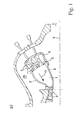
- Fig. 1 a shows a section through the middle part of a gas turbine, that is, the area between the compressor and turbine and the final stage of the compressor and the first stage of the turbine.
- a compressor 7 compresses the air. Most of the air is introduced via the Kompressplplenum 28 in an annular combustion chamber 1 and mixed with fuel, which burns there. From there, the hot fuel gases 10 flow under working discharge through a turbine 8, which rotates about an axis 9.
- the annular combustion chamber 1 is enclosed by an outer shell 3, an inner shell 2 and a front plate 5, through which fuel is introduced via burner 4 of the fuel premixed with compressed air.
- a portion of the compressor discharge air is before the introduction into the annular combustion chamber 1 on the inner shell 2 and outer shell 3 to Cooling passed along.
- To guide the cooling air is normally provided around the Brennschschen2, 3, an outer cooling air duct cover and an inner cooling air duct cover each in the form of cover plates.
- a burner cap 6 is arranged at the outlet of the cooling air guiding shell, in which there is a pressure below the compressor plenum pressure. From this, the air flows through the burner 4 or as a faceplate cooling air in the annular combustion chamber 1.
- the pressure loss between Kompressplenum 28 and annular combustion chamber 1 is thus divided into a part for the shell cooling and a part for front plate cooling or admixture in the burner 4.
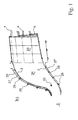
- FIG. 1 b shows a slightly different construction an annular combustion chamber, in which it has a first zone 23 which is segmented, and a second zone 24, which is circumferential.
- Inner shell 2 and outer shell 3 delimit this second zone 24.
- inner shell 2 and / or outer shell 3 typically have flange-like extensions, which are remote from the combustion chamber.
- the outer cooling air guide sheath and the inner cooling air duct cover can be seen, these are each in the form of cover plates 25, which are fastened with simultaneously serving as a spacer fasteners 26 to inner shell 2 and outer shell 3 on the outside.
- a channel 27 for guiding the cooling air as explained above is formed between the respective shell and the corresponding shell.
- Inner shell 2 and outer shell 3 are typically formed in the form of half shells guided around the burner axis by 180 °, in each case a lower half shell and an upper half shell.
- the lower half shell is specified, inserted axially to be attached central elements and then placed in each case the upper half shell.
- the inner half-shells 2a and 2b then abut against each other at edges lying substantially in a horizontal plane, and the outer half-shells 3a and 3b also butt against each other at edges lying substantially in a same horizontal plane (see, for example Fig. 2a ', 2b' ).
- the half-shells are connected with the help of a welding process after assembly, that is under very limited space.
- a substantially continuous sheathing surface for the combustion chamber is formed.
- this connecting line ie the weld at the abutment between the adjacent edges of the shroud sections
- the object of the invention is to be able to apply a thermal protective layer in this region of the connecting line, although the elements are already assembled and correspondingly the most difficult space conditions prevail.
- the sheets which form the half shells 2a / 2b and 3a / 3b, respectively, are provided on their side facing the combustion chamber over almost the entire surface with a thermal protection layer.
- Their typical structure is made FIG. 3 seen.
- a metallic-based bond coat 19 typically based on Ni, Al and Cr, or Co, Ni, Al and Cr, or Pt and Al based alloys, is disposed on the metallic base 2/3.
- the coatings may also be present in the form of structures of the formula III, where M is at least one element selected from the group Fe, Ni, Co, for example in the form of MAl, MAlY, MCrAl, MCrAlY or else PtAl.
- M is selected from the group Ni, Co, Fe and combinations thereof;
- X is an element selected from the group consisting of Y, Ta, Si, Hf, Ti, Zr, B, C and combinations thereof.
- a ceramic thermal protection layer 20 is arranged on this connection layer 19, which typically only adheres sufficiently to the substrate 2/3 as a result of the connection-mediating connection layer 19.
- This ceramic layer 20 is normally composed of 6-8% by weight yttria-stabilized zirconia (YSZ) as disclosed in U.S. Pat US 4,485,151 is known.
- YSZ yttria-stabilized zirconia
- thermal protection layer 21 the structure of bonding layer 19 and ceramic layer 20 will be referred to as thermal protection layer 21.
- the metallic interconnect layers and the ceramic layer can be applied with the aid of vapor deposition such as PVD, CVD, or thermal spraying methods, as well as plasma spray methods.
- the surfaces facing the combustion chamber do not have such a thermal protection layer 21, normally via a strip running along the edge, whereby a total exposed width of approximately 30 mm is produced, that is Each sheet has at the edge over a width of 10-15 mm does not have such a thermal protection layer. This, then to the formation of a weld 16 too enable.
- the present invention proposes both a new slurry formulation (ceramic suspension) which can be used under these conditions, as well as a novel rapid and straightforward process for applying such a slurry formulation for the construction of a thermal protection layer of sufficient thickness.
- the newly proposed slip formulation essentially comprises a ceramic binder, ceramic fillers and optionally other additives.
- the ceramic binder is substantially responsible for adhesion to the substrate, especially in the present situation where a metallic bond coat is desired.
- the thermal shock resistance is strongly influenced by the fillers.
- the thermal expansion coefficient of the filler should be as close as possible to that of the base material (substrate).
- the filler should have the lowest possible thermal conductivity, so as to ensure the highest possible thermal shielding.
- such a slip formulation is applied to a metallic surface (rolled material, milled material, with or without weld, for example between two half-shells for a combustion chamber) with a spatula, a roll, a brush or with an air spray in a few steps (not more than four application steps) applied and each between them dried until a layer thickness in the range of 0.4-1 mm is reached and finally dried and cured at the end.
- a metallic surface rolled material, milled material, with or without weld, for example between two half-shells for a combustion chamber
- a spatula, a roll, a brush or with an air spray in a few steps (not more than four application steps) applied and each between them dried until a layer thickness in the range of 0.4-1 mm is reached and finally dried and cured at the end.
- Inconel substrates 60x40x7mm
- sandpaper 50-90 grit
- This surface is then cleaned with organic solvents and degreased.
- the ceramic suspension is then applied in several layers until a total layer thickness of 0.2-0.8 mm is achieved (single layer thickness about 0.1-0.2 mm).
- the individual layers are e.g. with a hair dryer between 70 - 80 ° C for 1-3 minutes. The final drying of the whole layer takes place in an oven at 75-95 ° C for 4-16 hours.
- the performance of the layers thus produced is then tested in a thermal shock test at 1000 ° C.
- the sample is alternately immersed in a fluidized sand bath at 1000 ° C or 20 ° C.
- the number of cycles that the coating survives until first spalling occurs is referred to as the life of the layer.
- the layers produced with the described suspensions and the described method have reached 300-500 cycles in the thermal shock test, which is the requirement more than fulfilled for the planned application.
- aqueous sodium silicate solution (modulus 2.5, about 40% by weight of sodium silicate in water) are mixed with 96 g of yttria-stabilized zirconium oxide having an average particle size of 0.3 ⁇ m and stirred well with a wooden spatula.
- the mixture is then sonicated for 15 minutes. It forms a moderately viscous, homogeneous stable suspension, which can be well processed with a brush or a spray gun.
- aqueous alkali silicate solution As aqueous alkali silicate solution, however, a mixture of 60 g of the same sodium silicate solution (module 2.5) and 40 g of potassium silicate solution (module 2.4, about 35% by weight potassium silicate in water) is used. It also forms a homogeneous stable suspension, which can be processed well.
- Example 1 As a filler but 67 g of magnesium oxide are used with an average particle size of 0.05 microns. Also in this case, a homogeneous stable suspension with good processing properties.
- the substrate is previously sanded with 50-grit sandpaper and rinsed with acetone. After evaporation of the solvent, the sample is positioned vertically in a spray booth and coated step by step 5 times with the spray gun.
- the individual layers are then dried with the hair dryer for 2 minutes. Due to the optimized viscosity of the suspension, the individual layers do not run off and it forms a smooth homogeneous overall layer. The final drying takes place in the oven at 80 ° C for 10 hours. With a layer thickness gauge (eddy current method), a layer thickness of 0.4-0.5 mm is measured after drying.
- FIG. 2 shows two sectional views of a layer region 22 which can be produced by the proposed method.
- the respective half shells 2a / 2b and 3a / 3b abut one another (typically with flanks chamfered in a V) and the weld seam 16 is arranged on this joint.
- On the respective half-shells 2/3 is on the hot gas side 17 facing top - in contrast to the uncoated back 18 - already built a previously applied classic thermal protection layer 21, this includes, as already explained above, a compound layer 19 and on this the hot gas side 17th facing ceramic layer 20.
- the half-shells 2/3 are not equipped with such a thermal protection layer 21, ie over a width W 1 of about 15 mm, the metallic material of the elements 2/3 is simply exposed at each element on the edge.
- a chamfer 30 of the thermal protection layer 21 may be provided so that the subsequently applied strip 22 adheres better in the edge region.
- the width of the uncoated edge area including bevel / outlet zone W 2 is correspondingly increased compared to W 1 .
- the protective layer 22 is then applied to the weld seam 16 and to the upper-side exposed area of the elements 2/3. This can, on the one hand, as in FIG. 3a shown, done so that the surface of the region 22 is substantially flush with the surrounding layer 21 and a smooth surface is formed.
- the proposed protective layer 22 may also, as shown in FIG. 4 is simply used to make patches on a surface. It is thus not necessary for the protective layer 22 to be to some extent interposed between already existing regions of thermal protection layers 21, as shown in FIG. 3 is shown. Be like in FIG. 4 If such patches or strips are applied individually, then it proves to be advantageous to apply these patches or stripes on the patches Leaking edge with a discharge area of a width a of about 5 mm. Otherwise, the edge areas are too heavily loaded and can jump off.
- drying attachments can advantageously be used for the drying steps, as described in US Pat FIG. 2 are shown.
- FIG. 2a and 2a ' a first construction of such a drying attachment 11 is shown. It is in this construction is a box-shaped construction, in which to some extent a downwardly open and with an insulating layer 29 (this layer may be provided outside or inside with respect to a wall) provided box with a straight upper wall has lateral walls which the curvature in this case, the outer burner casing is adapted. Such a box, optionally using seals in the contact area 14, on the combustion chamber wall, the weld seam 16 are placed overlapping (see. FIG. 2a ' ).
- this box 11 is acted upon with hot air along the box 11 extending line 12 (for example, copper pipe) is provided, this line has holes (perforations), so that the hot air 13 distributed over the entire length of the box 11 flows out of this line 12 and so the entire weld 16 where a protective layer is applied, heat and so dry / harden (in the FIGS. 2a 'and 2b' in each case the applied protective layers are not shown for better visualization).
- line 12 for example, copper pipe
- this line has holes (perforations), so that the hot air 13 distributed over the entire length of the box 11 flows out of this line 12 and so the entire weld 16 where a protective layer is applied, heat and so dry / harden (in the FIGS. 2a 'and 2b' in each case the applied protective layers are not shown for better visualization).
- FIG. 2b an alternative design is shown. While a box behind FIG. 2a At the highest point it may well have a height of about 15 cm, this at a width of about 7-12 cm, the construction is according to FIG. 2b considerably flatter and has a height of about 2-4 cm with a width of about 7-16 cm.
- the box used here nestles over its entire length substantially to the contour of the combustion chamber and is located directly above the weld seam 16 to form a cavity with a small volume. In this cavity and attached to the drying attachment 11 heating wires 15 are arranged. For drying a protective layer 22, this elongated box or better this elongate cover is placed on the newly created protective layer 22 and the heater is connected to an electrical power source. Again, the box 11 is provided with an insulating layer 29.
Abstract
Description
Die vorliegende Erfindung betrifft eine verbesserte Schlickerformulierung (Keramiksuspension), welche zur Herstellung einer thermischen Schutzschicht eingesetzt werden kann, ein Verfahren zur Herstellung einer solchen Schlickerformulierung sowie ein Verfahren zur Herstellung einer thermischen Schutzschicht unter Verwendung einer solchen Schlickerformulierung.The present invention relates to an improved slurry formulation (ceramic suspension) that can be used to make a thermal barrier coating, a process for making such slurry formulation, and a process for making a thermal barrier coating using such slurry formulation.
Für die Bauweise von Gasturbinenbrennkammern gibt es mehrere verschiedene Ansätze. Einer davon ist die Verwendung von Ringbrennkammern, auf die sich die vorliegende Erfindung unter anderem bezieht. Dies sind ringförmige Brennkammern, die zwischen Verdichter und Turbine im wesentlichen rotationssymmetrisch um den Rotor der Gasturbine angeordnet sind. Über normalerweise eine Vielzahl von Brennern wird ein brennbares Gasgemisch in die Ringbrennkammer eingeleitet, das in dieser verbrennt und als ringförmiger Strom in die Turbine strömt. Der im wesentlichen ringförmige Raum wird nach innen, dass heisst zur Rotorseite durch eine sogenannte Innenschale oder inneren Brennerummantelung und nach aussen durch eine sogenannte Aussenschale oder äußere Brennerummantelung begrenzt. Diese Schalen bestehen häufig aus mehreren einzelnen Abschnitten, die verschweisst oder mechanisch miteinander verbunden sind und dabei die Baueinheit einer Gasturbine bilden. Die einzelnen Abschnitte können dabei, wie aus der
Zum Schützen der inneren und äusseren Brennerummantelung vor den hohen Temperaturen, die innerhalb der Brennkammer erzeugt werden, ist allgemein bekannt, die der Hitze ausgesetzten inneren Flächen mit einer thermischen Schutzschicht (thermal barrier coating/TBC) zu beschichten, wie zum Beispiel mit Yttriumoxid partiell stabilisiertes Zirkonoxid (YSZ), die einem Temperaturschock bis zu 1150 °C und einer Materialermüdung widersteht. Die YSZ-Schicht kann durch Plasmaspritzen oder durch Abscheidung aus der Dampfphase mittels Elektronenstrahl aufgebracht werden. Obwohl diese TBCs jederzeit verfügbar sind, können diese, wie aus der
So beschreibt beispielsweise die bereits genannte
Aus der
Die vorliegende Erfindung betrifft eine verbesserte Schlickerformulierung (Keramiksuspension), welche zur Herstellung einer thermischen Schutzschicht eingesetzt werden kann. Dies insbesondere ohne Verwendung einer separaten zusätzlichen Verbindungsschicht (bond coat) und auch auf besonders schwierigen Materialien, wie beispielsweise auf einer Schweissnaht, welche nicht sandgestrahlt wurde.The present invention relates to an improved slurry formulation (ceramic suspension) which can be used to prepare a thermal barrier coating. This in particular without the use of a separate additional bonding layer (bond coat) and also on particularly difficult materials, such as on a weld, which was not sandblasted.
Insbesondere betrifft die vorliegende Erfindung eine Schlickerformulierung für die Herstellung eines Patches oder eines Streifens aus einer thermischen Schutzschicht mit einem keramischen Binder, keramischen Füllstoffen und gegebenenfalls weiteren Additiven, wobei die Schlickerformulierung
20-60 Trocken-Gewichtsprozent Alkalisilikat-Binder;
40-80 Trocken-Gewichtsprozent keramische Füllstoffe ausgewählt aus der Gruppe: Yttriumoxid stabilisiertes Zirkonoxid, Magnesiumoxid, oder Mischungen davon;
0-20 Trocken-Gewichtsprozent Additive (wie z.B. Aluminiumphosphate, Microsilica, Metakaolin etc. ) aufweist, wobei sich die Trocken-Gewichtsanteile aller Bestandteile auf 100 % ergänzen;
sowie ein Lösungsmittel respektive Suspensionsmittel.In particular, the present invention relates to a slip formulation for the preparation of a patch or strip of a thermal protection layer comprising a ceramic binder, ceramic fillers and optionally further Additives, wherein the slip formulation
20-60 dry weight percent alkali silicate binder;
40-80 dry weight percent ceramic fillers selected from the group: yttria stabilized zirconia, magnesia, or mixtures thereof;
0-20% by dry weight of additives (such as aluminum phosphates, microsilica, metakaolin, etc.), with the dry parts by weight of all the constituents completing 100%;
and a solvent or suspending agent.
Die prinzipielle Haftung einer Schutzschicht unter Verwendung einer solchen Schlickerformulierung auf dem Substrat wird neben der genaueren Oberflächenbeschaffenheit in erster Linie durch den keramischen Binder vorgegeben. Typischerweise wird als Lösungsmittel respektive Suspensionsmittel Wasser verwendet. Generell wird bevorzugt, wenn die Schlickerformulierung eine Viskosität im Bereich von 50-5000 mPas aufweist, vorzugsweise von 500-1500 mPas. Vorzugsweise wird eine solche Viskosität eingestellt, indem der Anteil an Wasser (oder allgemeiner Lösungsmittel) entsprechend eingestellt wird kurz bevor die Schlickerformulierung aufgetragen wird und während respektive nachdem die Mischung erneut aufgemischt wurde.The basic adhesion of a protective layer using such a slip formulation on the substrate, in addition to the more precise surface finish, is predetermined primarily by the ceramic binder. Typically, water is used as the solvent or suspending agent. Generally, it is preferred if the slurry formulation has a viscosity in the range of 50-5,000 mPas, preferably 500-1500 mPas. Preferably, such a viscosity is adjusted by adjusting the proportion of water (or more generally solvent) just before the slurry formulation is applied and during or after the mixture has been remixed.
Als Additive kommen Aluminiumphosphate, Microsilica oder Metakaolin in Frage. Diese Additive können die Aushärtung und Entwässerung der Schicht beschleunigen.Suitable additives are aluminum phosphates, microsilica or metakaolin. These additives can accelerate the curing and dewatering of the layer.
Als keramische Binder sind für die vorgesehene Anwendung (Nickelbasislegierungen als Grundwerkstoff) besonders Alkalisilikate mit relativ hohem Alkalioxidanteil (Modul 2-3) geeignet. Es können auch Mischungen verschiedener Alkalisilikate eingesetzt werden. Durch die hohe Alkalikonzentration kommt es zu einer Anätzung der Metalloberfläche und es können sich zumindest partiell chemische Bindungen ausbilden.Suitable ceramic binders for the intended application (nickel-base alloys as the base material) are particularly alkali metal silicates with a relatively high proportion of alkali oxide (module 2-3). It is also possible to use mixtures of different alkali metal silicates. The high alkali concentration leads to etching of the metal surface and at least partial chemical bonds can form.
Entsprechend zeichnet sich gemäß einer bevorzugten Ausführungsform der Erfindung die Schlickerformulierung dadurch aus, dass es sich beim keramischen Binder um ein Alkalisilikat handelt oder eine Mischung von Alkalisilikaten, vorzugsweise mit einem Modul im Bereich von 1.8-3.5, wobei es sich vorzugsweise um Natriumsilikat und/oder Kaliumsilikat und/oder Lithiumsilikat mit einem Modul im Bereich von 2-2.5 handelt. Mit anderen Worten wird vorzugsweise ein System der allgemeinen Formel M2SixO2x+1 y H2O eingesetzt, in der M ein Alkalimetallion, x, das sogenannte Modul, eine Zahl von 1.8 bis 3.5 und y normalerweise eine Zahl von 0 bis 20 ist und bevorzugte Werte für x im Bereich von 2-2.5 sind.Accordingly, according to a preferred embodiment of the invention, the slip formulation is characterized in that the ceramic binder is an alkali silicate or a mixture of alkali silicates, preferably having a modulus in the range of 1.8-3.5, preferably sodium silicate and / or Potassium silicate and / or lithium silicate with a modulus in the range of 2-2.5 acts. In other words, it is preferable to use a system of the general formula M 2 Si x O 2 × + 1 y H 2 O in which M is an alkali metal ion, x, the so-called modulus, a number from 1.8 to 3.5 and y is normally a number from 0 to Is 20 and preferred values for x are in the range of 2-2.5.
Die Temperaturwechselbeständigkeit kann im wesentlichen durch die Füllstoffe beeinflusst werden. Dabei sollte der thermische Ausdehnungskoeffizient (CTE) des Füllstoffs möglichst nahe an demjenigen des Grundwerkstoffs liegen. Außerdem sollte der Füllstoff eine möglichst niedrige thermische Leitfähigkeit besitzen, damit eine möglichst gute thermische Abschirmung gewährleistet wird.The thermal shock resistance can be influenced essentially by the fillers. The thermal expansion coefficient (CTE) of the filler should be as close as possible to that of the base material. In addition, the filler should have the lowest possible thermal conductivity, so that the best possible thermal shielding is guaranteed.
Von den zur Verfügung stehenden keramischen Füllstoffen sind besonders Yttriumoxid stabilisiertes Zirconoxid und Magnesiumoxid geeignet, da deren thermische Ausdehnungskoeffizienten am besten mit dem von Inconel übereinstimmen.
Vorzugsweise verfügen also die Füllstoffe über einen Wärmeausdehnungskoeffizienten bei Raumtemperatur im Bereich von 10 (10E-6/K) - 15 (10E-6/K), besonders bevorzugt im Bereich von 12 (10E-6/K) - 14 (10E-6/K). Generell können entsprechend auch noch andere Materialien in typischerweise geringen Anteilen im Rahmen der Füllstoffe vorhanden sein, solange sie den Wärmeausdehnungskoeffizienten der entstehenden Schicht nicht aus diesem Bereich verschieben.Preferably, therefore, the fillers have a thermal expansion coefficient at room temperature in the range of 10 (10E-6 / K) - 15 (10E-6 / K), more preferably in the range of 12 (10E-6 / K) - 14 (10E-6 / K). Generally speaking, other materials may also be present in typically small proportions within the scope of the fillers, as long as they do not shift the thermal expansion coefficient of the resulting layer from this area.
Entscheidend für die Stabilität der Suspension und ihr Haftvermögen auf dem Substrat ist auch die mittlere Korngröße der Füllstoffe. Mit sub-µm-Pulvem (d50=0,01-1,00 µm) können über mehrere Tage stabile Suspensionen hergestellt werden, die auch nach längerer Lagerung wieder leicht redispergiert werden können. Beim Auftragen der Beschichtung findet keine Sedimentation des Füllstoffs auf die Substratoberfläche statt.Decisive for the stability of the suspension and its adhesion to the substrate is also the mean grain size of the fillers. Sub-micron powders (d50 = 0.01-1.00 μm) can be used to prepare stable suspensions over several days, which can easily be redispersed even after prolonged storage. When applying the coating no sedimentation of the filler takes place on the substrate surface.
Gemäß einer weiteren bevorzugten Ausführungsform ist die Schlickerformulierung dadurch gekennzeichnet, dass die keramischen Füllstoffe eine mittlere Korngröße (d50) im Bereich von 0.01-1 µm aufweisen.According to a further preferred embodiment, the slip formulation is characterized in that the ceramic fillers have an average particle size (d50) in the range of 0.01-1 μm.
Eine solche Suspension erlaubt die Reparatur auch in Bereichen beispielsweise einer Schweissnaht, wenn bevorzugtermassen die Substratoberfläche (Ni-Basislegierung) angeschliffen wird, so dass eine angeraute und metallisch reine Oberfläche entsteht, wenn, wie bevorzugt, Alkalisilikate (Li, Na, K) mit relativ hohem Alkalioxidanteil (Modul 2-3.5) eingesetzt werden (dadurch kommt es zum Anätzen der Metalloberfläche und es können sich chemische Bindungen ausbilden), Füllstoffe wie ZrO2 und MgO mit einem thermischen Ausdehnungskoeffizient in der Nähe der Ni-Basislegierung eingesetzt werden und die Korngröße der Füllstoffe im sub-µ-Bereich ausgewählt wird und Dispergierung mit z.B. Ultraschall erfolgt. Dadurch werden feine, stabile Suspensionen erzeugt, die eine gute Haftung auf dem Substrat gewährleisten.Such a suspension allows the repair also in areas such as a weld, if preferably the substrate surface (Ni-base alloy) is ground so that a roughened and metallically pure surface is formed when, as preferred, alkali metal silicates (Li, Na, K) with relative high alkali oxide content (module 2-3.5) are used (this leads to the etching of the metal surface and chemical bonds can form), fillers such as ZrO2 and MgO are used with a thermal expansion coefficient in the vicinity of the Ni-base alloy and the grain size of the fillers in the sub-μ range is selected and dispersion done with eg ultrasound. This produces fine, stable suspensions that ensure good adhesion to the substrate.
Zur Suspensionsherstellung wird der keramische Füllstoff (35-60 Gew.% bezogen auf die wässrige Suspension) bevorzugtermassen mit einer wässrigen Lösung des Binders gemischt und mit Hilfe eines Ultra-Turrax oder von Ultraschall dispergiert. Über die Menge des Füllstoffs kann die Viskosität der Suspension so eingestellt werden, dass sie durch Streichen oder Spritzen optimal verarbeitet werden kann. Die sorgfältige Dispergierung des Füllstoffs gewährleistet eine gute Deagglomeration der Pulverteilchen und die Ausbildung einer homogenen stabilen Suspension.To prepare the suspension, the ceramic filler (35-60% by weight, based on the aqueous suspension) is preferably mixed with an aqueous solution of the binder and dispersed by means of an Ultra-Turrax or by ultrasound. About the amount of the filler, the viscosity of the suspension can be adjusted so that it can be optimally processed by brushing or spraying. The careful dispersion of the filler ensures good deagglomeration of the powder particles and the formation of a homogeneous stable suspension.
Ausserdem betrifft die vorliegende Erfindung ein Verfahren zur Herstellung einer Schlickerformulierung, wie sie oben beschrieben wurde, welches insbesondere dadurch gekennzeichnet ist, dass eine wässrige Lösung des keramischen Binders mit dem keramischen Füllstoff versetzt und zu einer Suspension vermischt wird, vorzugsweise unter Behandlung in einem Mischer mit schnell rotierendem Messer wie beispielsweise einem Ultra-Turrax oder unter Behandlung mit Ultraschall, und gegebenenfalls anschließend die Viskosität unter Zugabe von Wasser eingestellt wird, vorzugsweise auf eine Viskosität der Schlickerformulierung im Bereich von 50-5000 mPas (je nachdem ob die Suspension mit dem Pinsel, der Spritzpistole oder einem Spachtel verarbeitet wird). Entscheidend für die Qualität und Leistungsfähigkeit der keramischen Suspensionen, die für thermische Schutzschichten auf Nickelbasislegierungen eingesetzt werden sollen, ist insbesondere die Kombination der beschriebenen Parameter (Art des keramischen Binders und Füllstoffs, mittlere Korngröße und Gewichtsanteil des Füllstoffs, Dispergierung des Füllstoffs).In addition, the present invention relates to a process for the preparation of a slip formulation, as described above, which is characterized in that an aqueous solution of the ceramic binder with the ceramic filler is added and mixed into a suspension, preferably with treatment in a mixer with fast rotating knife such as an Ultra-Turrax or under treatment with ultrasound, and optionally subsequently the viscosity is adjusted with the addition of water, preferably to a viscosity of the slip formulation in the range of 50-5000 mPas (depending on whether the suspension with the brush, the spray gun or a spatula is processed). Decisive for the quality and performance of the ceramic suspensions to be used for thermal protection coatings on nickel-based alloys, in particular the combination of the parameters described (type of ceramic binder and filler, average grain size and weight fraction of the filler, dispersion of the filler).
Für Testzwecke werden mit den beschriebenen Suspensionen auf Inconelsubstraten Beschichtungen durchgeführt, die Schichten getrocknet und anschließend mit Hilfe des Thermoschocktests geprüft.For test purposes, coatings are carried out on Inconel substrates with the suspensions described, the layers are dried and then tested by means of the thermal shock test.
Zudem betrifft die vorliegende Erfindung ein Verfahren zum Aufbau eines Bereiches (typischerweise lokal begrenzter Bereich wie beispielsweise Patch respektive Streifen) aus einer thermischen Schutzschicht mit einer Schlickerformulierung, wie sie oben beschrieben wurde.In addition, the present invention relates to a method of constructing a region (typically localized area such as patch or strip, for example) of a thermal barrier coating with a slurry formulation as described above.
Das Verfahren ist insbesondere dadurch gekennzeichnet, dass die Schlickerformulierung in 2-4 Auftragungsschritten (Ausnahmsweise können auch höchstens fünf oder sechs Auftragungsschritte eingesetzt werden, wenn besonders dicke Schichten aufgebaut werden sollen, oder es ist auch möglich, wenn beispielsweise eine besonders dünne Schicht aufgebaut werden soll, nur einen Auftragungsschritt durchzuführen) von normalerweise je 0.05-0.3 mm Schichtauftrag zu einer gesamten Schichtdicke von typischerweise 0.4-1 mm direkt auf ein metallisches Substrat, typischerweise im wesentlichen ohne Verbindungsschicht (im Randbereich zu angrenzenden thermischen Schutzschicht kann aber zum Beispiel noch Verbindungsschicht vorhanden sein) aufgetragen wird.The method is particularly characterized in that the slip formulation in 2-4 application steps (exceptionally, at most five or six application steps can be used if particularly thick layers are built up should, or it is also possible, for example, if a very thin layer is to be built to perform only one application step) of normally 0.05-0.3 mm layer order to a total layer thickness of typically 0.4-1 mm directly on a metallic substrate, typically substantially without connecting layer (in the edge region to adjacent thermal protective layer but may, for example, still be present connection layer) is applied.
Dabei wird bevorzugtermassen nach jedem Auftragungsschritt die bereits aufgetragene Schicht vorläufig getrocknet (z.B. mit einem Fön bei 70-80°C), und danach wird der gesamte Schichtaufbau in einem bevorzugt zweistufigen Trocknungsvorgang respektive Härtungsvorgang abgeschlossen. Dieser zweistufige Vorgang umfasst eine Langzeitbehandlung bei vergleichsweise niedriger Temperatur und eine Kurzzeitbehandlung bei vergleichsweise hoher Temperatur, so typischerweise folgende Schritte: Während wenigstens 6 h wird der gesamte Schichtaufbau bei einer Temperatur von 80-100 °C gehalten und anschließend während wenigstens 15 min bei einer Temperatur von wenigstens 400 °C.In this case, the already applied layer is preferably preliminarily dried (for example with a hair dryer at 70-80 ° C.) after each application step, and then the entire layer structure is completed in a preferably two-stage drying process or curing process. This two-step process involves a long-term treatment at a comparatively low temperature and a short-term treatment at a comparatively high temperature, typically the following steps: For at least 6 hours, the entire layer structure is maintained at a temperature of 80-100 ° C and then at a temperature for at least 15 minutes of at least 400 ° C.
Typischerweise erfolgt mit anderen Worten der Auftrag ohne aufwändiges Plasmaverfahren.Typically, in other words, the job takes place without a complex plasma process.
Bevorzugtermassen ist die Gesamtprozessdauer weniger als 24 h.Preferably, the total process time is less than 24 hours.
Eine bevorzugte Ausführungsform dieses Verfahrens ist dadurch gekennzeichnet, dass der zu beschichtende Oberflächenbereich vor der Auftragung der Schlickerformulierung gereinigt wird. Dies ist beispielsweise möglich unter Verwendung von Stahlbürsten, und/oder Schleifpapier und/oder Reinigungsflüssigkeiten. Eine besonders vorteilhafte Eigenschaft der vorgeschlagenen Schlickerformulierung ist es, dass es möglich ist, eine solche Vorbereitung der Oberfläche ohne Sandstrahlen durchzuführen und trotzdem eine genügende Haftung auf der Unterlage auch ohne Verbindungsschicht zu erzielen. Dies ist insbesondere dann von großem Vorteil, wenn, wie bevorzugt, das Verfahren unter sehr beschränkten Platzverhältnissen beispielsweise innerhalb einer montierten Gasturbine in der Brennkammer zur Überdeckung von Verbindungen (Schweißnähten) von Wandelementen derselben eingesetzt werden soll. Ist an solchen Stellen eine Strahlbehandlung der Oberfläche erforderlich, so entstehen dadurch hohe Aufwendungen, weil einerseits umgebende Bereiche abgedeckt werden müssen und andererseits das Strahlmaterial nach der Behandlung wieder aus den angrenzenden und umgebenden Bereichen entfernt werden muss.A preferred embodiment of this method is characterized in that the surface area to be coated is cleaned prior to application of the slip formulation. This is possible, for example, using steel brushes, and / or abrasive paper and / or cleaning fluids. A particularly advantageous feature of the proposed slip formulation is that it is possible to carry out such a preparation of the surface without sand blasting and nevertheless to achieve sufficient adhesion to the substrate even without a bonding layer. This is particularly advantageous if, as is preferred, the method is to be used under very limited space conditions, for example within a mounted gas turbine in the combustion chamber for covering connections (welds) of wall elements thereof. If a beam treatment of the surface is required at such locations, high expenditures arise because, on the one hand, surrounding areas must be covered and, on the other hand, the blasting material has to be removed again from the adjacent and surrounding areas after the treatment.
Eine weitere bevorzugte Ausführungsform des Verfahrens ist dadurch gekennzeichnet, dass die Schlickerformulierung jeweils unter Zuhilfenahme eines Pinsels, einer Rolle, eines Spachtels und/oder einer Spitzpistole aufgetragen wird. Mit anderen Worten erlaubt es die vorgeschlagene Schlickerformulierung aufgrund ihrer Eigenschaften, auf aufwändige Auftragungsmethoden wie beispielsweise Plasma-Verfahren zu verzichten, was es ermöglicht, das vorgeschlagene Verfahren wiederum auch unter sehr beschränkten Platzverhältnissen beispielsweise wie oben beschrieben innerhalb einer montierten Gasturbine der Brennkammer einzusetzen und ohne übermäßigen apparativen Aufwand. Typischerweise wird beim abschließenden Behandlungsschritt des gesamten Schichtaufbaus dieser während wenigstens 6 h bei einer Temperatur von im Bereich von 95 °C und anschließend während 15-30 min bei einer Temperatur im Bereich von 400 °C getrocknet und ausgehärtet.A further preferred embodiment of the method is characterized in that the slip formulation is applied in each case with the aid of a brush, a roller, a spatula and / or a pointed gun. In other words, because of its properties, the proposed slip formulation allows to dispense with expensive application methods such as plasma processes, which makes it possible to use the proposed method even in very limited space, for example as described above within a mounted gas turbine combustion chamber and without excessive equipment expense. Typically, in the final treatment step of the entire layer construction, it is dried and cured for at least 6 hours at a temperature of in the range of 95 ° C and then for 15-30 minutes at a temperature in the range of 400 ° C.
Insbesondere bei Einsatz des Verfahrens bei montierter Gasturbine respektive genauer bei montierter Brennkammer zur Verbindung der Wandelemente (Halbschalen) ist es von großem Vorteil, wenn nach jedem Auftragungsschritt die jeweils bereits vorhandenen Schichten und/oder der gesamte Schichtaufbau unter Zuhilfenahme eines auf den neu beschichteten Bereich aufgesetzten und diesen im wesentlichen vollständig überdeckenden Trocknungsaufsatzes getrocknet und ausgehärtet wird. Ein solcher Trocknungsaufsatz kann aufgrund der Symmetrie einer Brennkammer und der dabei eingesetzten Schweißnähte (typischerweise axial verlaufend und entsprechend sind normalerweise alle Schweißnähte in einer gleichen oder wenigstens ähnlichen Oberflächentopologie angeordnet) häufig für alle Schweißnähte ausgelegt werden.In particular when using the method when the gas turbine is mounted or more precisely when the combustion chamber is mounted to connect the wall elements (half shells), it is of great advantage if, after each application step, the respective already existing layers and / or the entire layer structure are placed with the aid of a newly coated area and dried and cured this substantially completely covering drying attachment. Such a drying attachment can often be designed for all welds due to the symmetry of a combustion chamber and the welds used (typically axially extending and, accordingly, all welds are arranged in a same or at least similar surface topology).
Bevorzugtermassen handelt es sich beim Bereich, der mit der neuen Schicht überdeckt werden soll, um eine Schweissnaht, insbesondere um eine Schweissnaht zwischen Halbschalen (oder Viertelschalen) für eine Brennkammer.Preferably, the area to be covered with the new layer is a weld, in particular a weld between half-shells (or quarter shells) for a combustion chamber.
Der Trocknungsaufsatz hat insbesondere dann die Form eines einseitig offenen und im wesentlichen nur den beschichteten Bereich überdeckenden Kastens oder einer Abdeckung, deren Innenseite die Trocknung und/oder Aushärtung bevorzugen respektive beschleunigen kann, beispielsweise indem die Innenseite respektive der innenseitige Hohlraum mit Heißluft beaufschlagt wird oder mit einer elektrischen Widerstandsheizung geheizt wird (auch Lichtenergie oder eine andere Energieform kann eingetragen werden). Vorzugsweise ist dabei der Trocknungsaufsatz im wesentlichen entlang aller seiner Wände (seitlich und nach oben) mit einer Isolationsschicht versehen.The drying attachment in particular has the form of a box open on one side and covering substantially only the coated area or a cover whose inside can prefer or accelerate the drying and / or hardening, for example by applying hot air to the inside or the inside cavity an electric resistance heater is heated (light energy or another form of energy can be registered). Preferably, the drying attachment is provided with an insulating layer substantially along all its walls (laterally and upwardly).
Eine weitere bevorzugte Ausführungsform des vorgeschlagenen Verfahrens ist dadurch gekennzeichnet, dass es zur Beschichtung von dem Heissgasstrom ausgesetzten Bereichen in einer Gasturbine bei im wesentlichen im entsprechenden Bereich zusammengesetzter Gasturbine durchgeführt wird.A further preferred embodiment of the proposed method is characterized in that it is carried out for coating areas exposed to hot gas flow in a gas turbine with a gas turbine which is essentially composed in the corresponding area.
Das Verfahren kann also zur Beschichtung der Schweissnaht zwischen Wandungsbereichen der Brennkammer eingesetzt werden, typischerweise angrenzend an bereits vorhandene thermische Schutzschichten auf den aneinander grenzenden Wandungsbereichen. Vorzugsweise haben solche bereits vor der Montage auf den Wandungsbereichen innenseitig vorgesehene thermische Schutzschichten eine Dicke im Bereich von 0.4-1.5 mm. Die thermischen Schutzschichten erstrecken sich dabei normalerweise nicht bis ganz an die Kante, wo die Schweissnaht angeordnet ist, typischerweise ist im Kantenbereich der Wandungsbereiche ein Oberflächen-Streifen einer Breite von 5-15 mm nicht mit einer solchen thermischen Schutzschicht versehen.The method can therefore be used for coating the weld seam between wall regions of the combustion chamber, typically adjacent to already existing thermal protection layers on the adjoining wall regions. Such thermal protection layers, which are provided on the inside of the wall areas before assembly, preferably have a thickness in the range of 0.4-1.5 mm. The thermal protective layers normally do not extend all the way to the edge where the weld seam is arranged, typically a surface strip of a width of 5-15 mm is not provided with such a thermal protective layer in the edge region of the wall regions.
Die Beschichtung über der Schweissnaht verfügt typischerweise über eine gesamte Breite im Bereich von 10-40 mm (jeweils normalerweise 5-20 mm über einem der beiden verbundenen Wandelemente), vorzugsweise im Bereich von 20-35 mm, wobei vorzugsweise die jeweils angrenzende bereits vorher aufgetragene thermische Schutzschicht auf dem jeweiligen Wandelement eine Abschrägung mit einer Breite im Bereich von 2-10 mm aufweist.The coating over the weld typically has a total width in the range of 10-40 mm (each usually 5-20 mm above either connected wall element), preferably in the range of 20-35 mm, preferably the adjacent one already applied previously thermal protection layer on the respective wall element has a chamfer with a width in the range of 2-10 mm.
Des weiteren betrifft die vorliegende Erfindung eine Brennkammer (oder eine Gasturbine mit einer solchen Brennkammer) mit wenigstens einer aus mit Schweißnähten verbundenen Elementen gefügten Brennkammerwand, wobei wenigstens eine Schweissnaht mit einer durch einen nach einem Verfahren wie oben beschrieben hergestellten Schutzschichtbereich (Patch, Streifen) unmittelbar (das heißt typischerweise im wesentlichen ohne Verbindungsschicht oder höchstens im Randbereich mit Verbindungsschicht) überdeckt ist.Furthermore, the present invention relates to a combustion chamber (or a gas turbine having such a combustion chamber) with at least one combustion chamber wall joined with elements joined by welds, wherein at least one weld seam having a protective layer area (patch, strip) prepared by a method as described above immediately (that is typically substantially without connecting layer or at most in the edge region with connecting layer) is covered.
Weitere Ausführungsbeispiele sind in den abhängigen Ansprüchen beschrieben.Further embodiments are described in the dependent claims.
Bevorzugte Ausführungsformen der Erfindung werden im Folgenden anhand der Zeichnungen beschrieben, die lediglich zur Erläuterung dienen und nicht einschränkend auszulegen sind. In den Zeichnungen zeigen:
- Fig. 1
- in a) einen axialen Schnitt durch die Mittelpartie einer Gasturbine mit
- Fig. 2
- Ringbrennkammer gemäß einer ersten Bauweise und in b) gemäß einer zweiten Bauweise mit Brennkammer mit zwei Zonen, in a) einen axialen Teilschnitt durch eine Brennkammer mit eingesetztem Trocknungsaufsatz gemäß einem ersten Ausführungsbeispiel und in a') einen Schnitt entlang der Linie A-A in
Figur 2 a)Figur 2 b - Fig. 3
- Schnitte im wesentlichen senkrecht zur Verlaufsrichtung der Schweissnaht zwischen den Halbschalen in einer Ebene im wesentlichen senkrecht zu den Halbschalen, wobei in a) eine Situation dargestellt ist, in welcher der auf die Schweissnaht aufgetragene Schutzschichtbereich ungefähr die gleiche Dicke hat wie die thermische Schutzschicht auf den Halbschalen, in b) eine Situation dargestellt ist, in welcher der auf die Schweissnaht aufgetragene Schutzschichtbereich dünner ist als die thermische Schutzschicht auf den Halbschalen; und
- Fig.4
- einen Schnitt im wesentlichen senkrecht zur Verlaufsrichtung der Schweissnaht zwischen den Halbschalen in einer Ebene im wesentlichen senkrecht zu den Halbschalen, wobei zwei Patches aus Schutzschichtbereich auf Halbschalen ohne thermische Schutzschicht aufgebracht sind.
- Fig. 1
- in a) an axial section through the central part of a gas turbine with
- Fig. 2
- Ring combustion chamber according to a first construction and in b) according to a second construction with combustion chamber with two zones, in a) an axial partial section through a combustion chamber with inserted drying attachment according to a first embodiment and in a ') a section along the line AA in
FIG. 2 a) , and in b) an axial partial section through a combustion chamber with inserted drying attachment according to a second embodiment and in b ') a section along the line BB inFIG. 2 b . - Fig. 3
- Sections substantially perpendicular to the direction of the weld between the half-shells in a plane substantially perpendicular to the half-shells, wherein in a) a situation is shown in which the protective layer applied to the weld has approximately the same thickness as the thermal protection layer on the half-shells in b) a situation is illustrated in which the protective layer area applied to the weld seam is thinner than the thermal protection layer on the half-shells; and
- Figure 4
- a section substantially perpendicular to the direction of the weld between the half-shells in a plane substantially perpendicular to the half-shells, wherein two patches of protective layer area are applied to half-shells without thermal protection layer.
Ein Kompressor 7 verdichtet die Luft. Der grösste Teil der Luft wird über das Kompressorplenum 28 in eine Ringbrennkammer 1 eingeleitet und mit Brennstoff vermischt, der dort verbrennt. Von dort strömen die heissen Brenngase 10 unter Arbeitsabgabe durch eine Turbine 8 ab, welche um eine Achse 9 rotiert. Die Ringbrennkammer 1 wird von einer Aussenschale 3, einer Innenschale 2 und einer Frontplatte 5, durch die über Brenner 4 der mit Kompressorendluft vorgemischte Brennstoff eingeleitet wird, umschlossen. Ein Teil der Kompressorendluft wird vor der Einleitung in die Ringbrennkammer 1 an der Innenschale 2 und Aussenschale 3 zur Kühlung entlang geleitet. Zur Führung der Kühlluft wird normalerweise um die Brennkammerschalen2, 3 eine äussere Kühlluftführungshülle und eine innere Kühlluftführungshülle jeweils in Form von Abdeckblechen vorgesehen. Um eine Druckdifferenz zu erzeugen, die die Kühlluft zwischen Kühlluftführungshülle und Brennkammerschale entlang strömen lässt, ist am Austritt der Kühlluftführungshülle eine Brennerhaube 6 angeordnet, in der ein unter dem Kompressorplenumdruck liegender Druck herrscht. Von dieser fliesst die Luft über die Brenner 4 oder als Frontplattenkühlluft in die Ringbrennkammer 1. Der Druckverlust zwischen Kompressorplenum 28 und Ringbrennkammer 1 wird damit in einen Teil zur Brennschalenkühlung und einen Teil zur Frontplattenkühlung bzw. Zumischung in die Brenner 4 aufgeteilt.A compressor 7 compresses the air. Most of the air is introduced via the
Innenschale 2 und Außenschale 3 sind dabei typischerweise in Form von 180° um die Brennerachse geführte Halbschalen ausgebildet, jeweils eine untere Halbschale und eine obere Halbschale. Bei der Montage wird die untere Halbschale vorgegeben, die axial anzubringenden zentralen Elemente eingelegt und anschliessend jeweils die obere Halbschale aufgelegt. Die inneren Halbschalen 2a und 2b stoßen anschließend an im wesentlichen in einer horizontalen Ebene liegenden Kanten aneinander, und die äußeren Halbschalen 3a und 3b stoßen ebenfalls an im wesentlichen in einer gleichen horizontalen Ebene liegenden Kanten aneinander (siehe beispielsweise
Der Bereich dieser Verbindungslinie (d.h. der Schweissnaht an der Angrenzung zwischen den benachbarten Kanten der Ummantelungsabschnitte) ist den hohen Temperaturen und den thermischen Belastungen während des Betreibens der Gasturbine ausgesetzt. Gegenstand der Erfindung ist es, in diesem Bereich der Verbindungslinie eine thermische Schutzschicht aufbringen zu können, obwohl die Elemente bereits zusammengebaut sind und entsprechend schwierigste Platzverhältnisse herrschen.The area of this connecting line (ie the weld at the abutment between the adjacent edges of the shroud sections) is exposed to the high temperatures and thermal stresses during operation of the gas turbine. The object of the invention is to be able to apply a thermal protective layer in this region of the connecting line, although the elements are already assembled and correspondingly the most difficult space conditions prevail.
Tatsächlich sind die Bleche, welche die Halbschalen 2a/2b respektive 3a/3b bilden, auf ihrer der Brennkammer zugewandten Seite über beinahe die gesamte Oberfläche mit einer thermischen Schutzschicht versehen. Deren typischer Aufbau ist aus
Auf dieser Verbindungsschicht 19 ist eine keramische thermische Schutzschicht 20 angeordnet, welche typischerweise nur infolge der Verbindung vermittelnden Verbindungsschicht 19 auf dem Substrat 2/3 genügend haftet. Diese keramische Schicht 20 besteht normalerweise aus mit 6-8 Gewichtsprozent Yttriumoxid stabilisiertem Zirkonoxid (YSZ), wie es aus der
Die metallischen Verbindungsschichten sowie die keramische Schicht können unter Zuhilfenahme von Dampfabscheidung wie beispielsweise PVD, CVD, oder thermischen Sprühmethoden, sowie auch Plasmaspray Methoden aufgebracht werden.The metallic interconnect layers and the ceramic layer can be applied with the aid of vapor deposition such as PVD, CVD, or thermal spraying methods, as well as plasma spray methods.
Im Randbereich, und zwar dort, wo die zwei Halbschalen aneinandergrenzen, verfügen die der Brennkammer zugewandten Oberflächen nicht über eine solche thermische Schutzschicht 21, dies normalerweise über einen der Kante entlang verlaufenden Streifen wobei eine gesamte frei liegende Breite von circa 30 mm entsteht, das heißt jedes Blech verfügt am Rand über eine Breite von 10-15 mm nicht über eine solche thermische Schutzschicht. Dies, um anschließend die Ausbildung einer Schweissnaht 16 zu ermöglichen.In the edge region, namely where the two half-shells adjoin one another, the surfaces facing the combustion chamber do not have such a
Unter Verwendung der heute üblichen Verfahren zum Aufbringen einer thermischen Schutzschicht ist es nicht möglich, diesen Bereich der Schweissnaht 16 mit einer thermischen Schutzschicht zu versehen. Deshalb auch die eingangs genannten aufwändigen konstruktiven Schutzmaßnahmen aus dem Stand der Technik zur Vermeidung einer Überhitzung der Schweissnaht und der daran angrenzenden Bereiche, indem beispielsweise zusätzliche Kühlluftströme oder separate über der Schweissnaht angeordnete Hitzeschilde angeordnet werden. Problematisch ist im Zusammenhang mit dem Aufbringen einer thermischen Schutzschicht einerseits die Tatsache, dass im montierten Zustand (und nur in diesem können die Halbschalen miteinander verschweißt werden) eine Oberflächenbehandlung wie Sandstrahlen oder die Verwendung einer Technologie wie Plasma-Spraymethode so gut wie unmöglich ist (Schutzmaßnahmen, Reinigungsmaßnahmen, keine Automatisierung on-site möglich nach der Trennebenenschweissung der Verbindungsnaht). Des weiteren ermöglichen es die Auftragungsverfahren und die zur Verfügung stehenden Materialien nach dem Stand der Technik nicht, in wenigen Schritten eine genügende Schichtdicke aufzubauen. Entsprechend schlägt die vorliegende Erfindung sowohl eine neue Schlickerformulierung (Keramiksuspension) vor, welche unter diesen Bedingungen eingesetzt werden kann, als auch ein neuartiges schnelles und unkompliziertes Verfahren zum Aufbringen einer solchen Schlickerformulierung für den Aufbau einer thermischen Schutzschicht von genügender Dicke.Using today's conventional method for applying a thermal protection layer, it is not possible to provide this region of the
Die neu vorgeschlagene Schlickerformulierung umfasst im wesentlichen einen keramischen Binder, keramische Füllstoffe und gegebenenfalls weitere Additive. Der keramische Binder ist wesentlich verantwortlich für die Haftung auf dem Substrat, insbesondere in der vorliegenden Situation, wo auf eine metallische Verbindungsschicht (bond coat) verzichtet werden soll. Die Temperaturwechselbeständigkeit wird stark durch die Füllstoffe beeinflusst. Der thermische Ausdehnungskoeffizient des Füllstoffes sollte möglichst nah an demjenigen des Grundwerkstoffs (Substrat) liegen. Zudem sollte der Füllstoff eine möglichst niedrige thermische Leitfähigkeit besitzen, damit eine möglichst hohe thermische Abschirmung gewährleistet wird.The newly proposed slip formulation essentially comprises a ceramic binder, ceramic fillers and optionally other additives. The ceramic binder is substantially responsible for adhesion to the substrate, especially in the present situation where a metallic bond coat is desired. The thermal shock resistance is strongly influenced by the fillers. The thermal expansion coefficient of the filler should be as close as possible to that of the base material (substrate). In addition, the filler should have the lowest possible thermal conductivity, so as to ensure the highest possible thermal shielding.
Auf dem Markt gibt es eine ganze Reihe von keramischen Klebern und Lacken, die zur Herstellung von thermischen Schutzschichten angeblich geeignet sein sollen. Eine Anwendung auf Nickelbasislegierungen bei 1000-1100 °C ist allerdings bei solchen kommerziellen Systemen nicht erwähnt. Laborversuche sowie Feldversuche unter Verwendung von solchen kommerziellen Systemen haben gezeigt, dass sie für die vorgesehene Anwendung auf einer Schweissnaht in einer Brennkammer unbrauchbar sind. In einem Vergleichsexperiment wurden zum Beleg dieser Tatsache Inconel 617-Substrate durch Streichen mit kommerziellen Keramiksuspensionen beschichtet und nach Herstellerangaben getrocknet (Schichtdicke 0.1-0.3 mm). Im Thermoschocktest (5 min im fluidisierten Sandbad bei 1000°C und 5 min im fluidisierten Sandbad bei 20°C entsprechen einem Zyklus) wurde die Beständigkeit der Schichten getestet. Allerdings zeigt es sich, dass die Schutzschichten unter Verwendung von kommerziellen Materialien schon nach wenigen Zyklen abgeplatzt waren und somit für die vorgesehene Anwendung ungeeignet sind. Entsprechend verfügen die kommerziellen Schlickerformulierungen respektive daraus hergestellte thermische Schutzschichten nicht über eine genügende Haftung auf dem Grundwerkstoff und nicht über eine genügende Temperaturwechselbeständigkeit. Die entsprechenden Resultate sind in der folgenden Tabelle zusammengestellt:
Gefordert wird aber im genannten Thermoschocktest eine Mindestlebensdauer von 200 thermischen Zyklen. Dies wird durch die thermischen Schutzschichten auf Basis der neu vorgeschlagenen Schlickerformulierung ohne weiteres erreicht. Tatsächlich werden 300-500 Zyklen erreicht, wenn die vorgeschlagenen Schlickerformulierungen verwendet werden.However, a minimum service life of 200 thermal cycles is required in the abovementioned thermal shock test. This is easily achieved by the thermal protection layers based on the newly proposed slip formulation. In fact, 300-500 cycles are achieved when using the proposed slurry formulations.
Nach der Erfindung wird eine solche Schlickerformulierung auf eine metallische Oberfläche (gerolltes Material, gefrästes Material, mit oder ohne Schweissnaht, beispielsweise zwischen zwei Halbschalen für eine Brennkammer) mit einem Spachtel, einer Rolle, einem Pinsel oder mit einem Luftsprühverfahren in wenigen Schritten (nicht mehr als vier Auftragungsschritte) aufgetragen und jeweils dazwischen angetrocknet bis eine Schichtdicke im Bereich von 0.4-1 mm erreicht ist und am Ende abschließend getrocknet und ausgehärtet. So können derartige Patches respektive Streifen beispielsweise über einer Schweissnaht zwischen solchen Halbschalen innerhalb eines Tages auch unter den engen Platzverhältnissen in der montierten Brennkammer einfach und schnell hergestellt werden.According to the invention, such a slip formulation is applied to a metallic surface (rolled material, milled material, with or without weld, for example between two half-shells for a combustion chamber) with a spatula, a roll, a brush or with an air spray in a few steps (not more than four application steps) applied and each between them dried until a layer thickness in the range of 0.4-1 mm is reached and finally dried and cured at the end. Thus, such patches or strips, for example, over a weld between such shells within a day even under the tight space conditions in the assembled combustion chamber can be easily and quickly produced.
So ist es möglich, den Bereich (beispielsweise im Bereich der Schweissnaht) vor Hitze und Korrosion zu schützen. Des weiteren ist es möglich, aufgrund der speziellen gewählten Schlickerformulierung, auf die Verwendung einer Verbindungsschicht (bond coat) vollständig zu verzichten, und es kann auch auf ein Sandstrahlen der Oberfläche vor dem auftragen der Schlickerformulierung verzichtet werden. Es ist kein schweres aufwändiges Plasma-Equipment erforderlich, wie dies für die normalen TBC Auftragungsverfahren erforderlich ist. Es kann innerhalb eines Tages eine solche Schicht vollständig aufgebaut werden, ein solcher Schichtaufbau kann auch wiederholt aufgetragen werden und beispielsweise für die lokale Reparatur bei Inspektionen eingesetzt werden.It is thus possible to protect the area (for example in the area of the weld seam) from heat and corrosion. Furthermore, due to the particular selected slip formulation, it is possible to completely dispense with the use of a bond coat, and sanding of the surface prior to application of the slip formulation may also be dispensed with. There is no need for a heavy-duty plasma equipment as required for normal TBC application procedures. It can be completely built within a day, such a layer, such a layer structure can also be repeatedly applied and used for example for local repair during inspections.
Nachfolgend werden einige Ausführungsbeispiele beschrieben:Hereinafter, some embodiments will be described:
Zunächst werden die Inconelsubstrate (60x40x7mm) mit Sandpapier (50-90iger Körnung) angeschliffen, so dass eine angerauhte, metallisch-saubere Oberfläche ensteht. Diese Oberfläche wird dann noch mit organischen Lösungsmitteln gereinigt und entfettet.First the Inconel substrates (60x40x7mm) are sanded with sandpaper (50-90 grit), so that a roughened, metallically clean surface is created. This surface is then cleaned with organic solvents and degreased.
Mit Hilfe eines Pinsels oder einer Spritzpistole wird anschließend die Keramiksuspension in mehreren Schichten aufgetragen bis eine Gesamtschichtdicke von 0,2-0,8mm erreicht ist (Einzelschichtdicke ca. 0,1-0,2 mm). Die Einzelschichten werden z.B. mit einem Fön 1-3 min bei 70-80°C zwischengetrocknet. Die Endtrocknung der Gesamtschicht erfolgt in einem Ofen bei 75-95°C für 4-16 Stunden.With the help of a brush or a spray gun, the ceramic suspension is then applied in several layers until a total layer thickness of 0.2-0.8 mm is achieved (single layer thickness about 0.1-0.2 mm). The individual layers are e.g. with a hair dryer between 70 - 80 ° C for 1-3 minutes. The final drying of the whole layer takes place in an oven at 75-95 ° C for 4-16 hours.
Die Leistungsfähigkeit der so hergestellten Schichten wird dann in einem Thermoschocktest bei 1000°C überprüft. Dabei taucht die Probe abwechselnd in ein fluidisiertes Sandbad mit 1000°C bzw. 20°C ein. Die Zahl der Zyklen, die die Beschichtung überlebt bis erste Abplatzungen auftreten wird als Lebensdauer der Schicht bezeichnet.The performance of the layers thus produced is then tested in a thermal shock test at 1000 ° C. The sample is alternately immersed in a fluidized sand bath at 1000 ° C or 20 ° C. The number of cycles that the coating survives until first spalling occurs is referred to as the life of the layer.
Die mit den beschriebenen Suspensionen und dem beschriebenen Verfahren hergestellten Schichten haben im Thermoschocktest 300-500 Zyklen erreicht, was die Anforderungen für die geplante Anwendung mehr als erfüllt.The layers produced with the described suspensions and the described method have reached 300-500 cycles in the thermal shock test, which is the requirement more than fulfilled for the planned application.
100 g einer wässrigen Natriumsilikatlösung (Modul 2,5; ca. 40 Gew.-% Natriumsilikat in Wasser) werden mit 96 g Yttriumoxid stabilisiertem Zirkonoxid mit einer mittleren Korngröße von 0,3 µm gemischt und mit einem Holzspatel gut verrührt.100 g of an aqueous sodium silicate solution (modulus 2.5, about 40% by weight of sodium silicate in water) are mixed with 96 g of yttria-stabilized zirconium oxide having an average particle size of 0.3 μm and stirred well with a wooden spatula.
Anschließend wird die Mischung 15 min lang mit Ultraschall behandelt. Es bildet sich eine mäßig viskose, homogene stabile Suspension, die mit einem Pinsel oder einer Spritzpistole gut verarbeitet werden kann.The mixture is then sonicated for 15 minutes. It forms a moderately viscous, homogeneous stable suspension, which can be well processed with a brush or a spray gun.
Wie Beispiel 1, als wässrige Alkalisilikatlösung wird allerdings eine Mischung aus 60 g derselben Natriumsilikatlösung (Modul 2,5) und 40 g Kaliumsilikatlösung (Modul 2,4; ca. 35 Gew.-% Kaliumsilikat in Wasser ) eingesetzt. Es bildet sich ebenfalls eine homogene stabile Suspension aus, die gut verarbeitet werden kann.As example 1, as aqueous alkali silicate solution, however, a mixture of 60 g of the same sodium silicate solution (module 2.5) and 40 g of potassium silicate solution (module 2.4, about 35% by weight potassium silicate in water) is used. It also forms a homogeneous stable suspension, which can be processed well.
Wie Beispiel 1, als Füllstoff werden allerdings 67 g Magnesiumoxid mit einer mittleren Korngröße von 0,05 µm eingesetzt. Auch in diesem Fall entsteht eine homogene stabile Suspension mit guten Verarbeitungseigenschaften.As Example 1, as a filler but 67 g of magnesium oxide are used with an average particle size of 0.05 microns. Also in this case, a homogeneous stable suspension with good processing properties.
Mit der Keramiksuspension aus Beispiel 1 wird mit Hilfe einer Druckluftspritzpistole ein Inconelsubstrat (LängexBreitexDicke=60x40x7mm) beschichtet. Das Substrat wird vorher mit Schleifpapier (50iger Körnung) abgeschliffen und mit Aceton abgespült. Nach dem Verdunsten des Lösungsmittels wird die Probe senkrecht in einer Spritzkabine positioniert und mit der Spritzpistole schrittweise 5 mal beschichtet. Die einzelnen Schichten werden mit dem Fön 2 min zwischengetrocknet. Aufgrund der optimierten Viskosität der Suspension laufen die Einzelschichten nicht ab und es bildet sich eine glatte homogene Gesamtschicht aus. Die Endtrocknung erfolgt im Ofen bei 80°C für 10 Stunden. Mit einem Schichtdickenmessgerät (Wirbelstromverfahren) wird nach dem Trocknen eine Schichtdicke von 0,4 -0,5 mm gemessen.With the ceramic suspension from example 1, an inconel substrate (length × width × thickness = 60 × 40 × 7 mm) is coated with the aid of a compressed air spray gun. The substrate is previously sanded with 50-grit sandpaper and rinsed with acetone. After evaporation of the solvent, the sample is positioned vertically in a spray booth and coated step by
Beim Thermoschocktest im fluidisierten Sandbad (1 Zyklus = 5 min bei 1000°C + 5min bei 20°C) erreicht die Probe eine Lebensdauer von 430 Zyklen.Thermal shock test in a fluidized sand bath (1 cycle = 5 min at 1000 ° C + 5min at 20 ° C), the sample reaches a lifetime of 430 cycles.
In
Im aneinander stoßenden Randbereich sind die Halbschalen 2/3 nicht mit einer solchen thermischen Schutzschicht 21 ausgestattet, d. h. über eine Breite W1 von ca. 15 mm liegt bei jedem Element am Rand das metallische Material der Elemente 2/3 einfach frei. Dabei kann eine Abschrägung 30 der thermischen Schutzschicht 21 vorgesehen sein, damit der nachträglich aufgebrachte Streifen 22 im Randbereich besser anhaftet. Die Breite des unbeschichteten Randbereiches inklusive Abschrägung/Auslaufzone W2 ist gegenüber W1 entsprechend vergrössert.In the abutting edge region, the half-
Unter Verwendung des vorgeschlagenen Verfahrens wird nun auf die Schweissnaht 16 und auf den oberseitig freiliegenden Bereich der Elemente 2/3 die Schutzschicht 22 aufgetragen. Dies kann einerseits, wie in
Es ist aber auch möglich, wie dies in
Die vorgeschlagene Schutzschicht 22 kann auch, wie dies in
Zur erfolgreichen Durchführung des Verfahrens können dabei vorteilhafterweise für die Trocknungsschritte Trocknungsaufsätze eingesetzt werden, wie sie in
In
In
- 11
- ringförmige Brennkammerannular combustion chamber
- 22
- innere Brennerummantelunginner burner jacket
- 2a2a
- obere Halbschale von 2upper half shell of 2
- 2b2 B
- untere Halbschale von 2lower half shell of 2
- 33
- äußere Brennerummantelungouter burner jacket
- 3a3a
- obere Halbschale von 3upper half shell of 3
- 3b3b
- untere Halbschale von 3lower half shell of 3
- 44
- DoppelkegelbrennerDouble-cone burner
- 55
- Frontplattefront panel
- 66
- Brennerhaubeburner hood
- 77
- Kompressorcompressor
- 88th
- Turbineturbine
- 99
- Achseaxis
- 1010
- heißer Verbrennungsluftstromhot combustion air flow
- 1111
- Trocknungsaufsatzdrying tower
- 1212
- HeißluftleitungHot air duct
- 1313
- ausströmende Luft aus 12outgoing air from 12
- 1414
- Kontaktbereich zwischen 2/3 und 11Contact area between 2/3 and 11
- 1515
- Heizdrähteheating wires
- 1616
- SchweissnahtWeld
- 1717
- HeissgasseiteHot-gas side
- 1818
- Rückseiteback
- 1919
- Verbindungsschicht (bond coat, BC)Bonding layer (BC)
- 2020
- keramische Schichtceramic layer
- 2121
- thermische Schutzschicht (thermal barrier coating, TBC)thermal barrier coating (TBC)
- 2222
- SchutzschichtbereichProtective layer region
- 2323
- ZoneZone
- 2424
-
Zone 2
Zone 2 - 2525
- äusseres Abdeckblechouter cover plate
- 2626
- Befestigungen/DistanzhalterFasteners / spacer
- 2727
- Hohlraum für KühlluftstromCavity for cooling air flow
- 2828
- Kompressorplenumcompressor plenary
- 2929
- Isolationsschichtinsulation layer
- 3030
- Abschrägung von 21Bevel of 21
- W1 W 1
- Breite des unbeschichteten Randbereichs von 2/3Width of the uncoated border area of 2/3
- W2 W 2
- Breite des unbeschichteten Randbereichs inklusive Abschrägung/AuslaufzoneWidth of the uncoated edge area including bevel / outlet zone
- dd
- Dicke der thermischen SchutzschichtThickness of the thermal protection layer
- d'd '
- Dicke des SchutzschichtbereichsThickness of the protective layer area
- aa
- Breite der Abschrägung/AuslaufzoneWidth of the chamfer / outlet zone
Claims (15)
20-60 Trocken-Gewichtsprozent Alkalisilikat-Binder;
40-80 Trocken-Gewichtsprozent keramische Füllstoffe ausgewählt aus der Gruppe: Yttriumoxid stabilisiertes Zirkonoxid, Magnesiumoxid, oder Mischungen davon;
0-20 Trocken-Gewichtsprozent Additive aufweist, wobei sich die Trocken-Gewichtsanteile aller Bestandteile auf 100 % ergänzen;
sowie ein Lösungsmittel respektive Suspensionsmittel.Slip formulation for the manufacture of a patch or strip of thermal barrier coating (22) comprising a ceramic binder, ceramic fillers and optionally further additives, wherein the slip formulation
20-60 dry weight percent alkali silicate binder;
40-80 dry weight percent ceramic fillers selected from the group: yttria stabilized zirconia, magnesia, or mixtures thereof;
0-20 dry weight percent additives, wherein the dry parts by weight of all ingredients supplement to 100%;
and a solvent or suspending agent.
Applications Claiming Priority (1)
| Application Number | Priority Date | Filing Date | Title |
|---|---|---|---|
| CH01014/09A CH701373A1 (en) | 2009-06-30 | 2009-06-30 | Schlickerformulierung for the manufacture of thermal barrier coatings. |
Publications (2)
| Publication Number | Publication Date |
|---|---|
| EP2281789A1 true EP2281789A1 (en) | 2011-02-09 |
| EP2281789B1 EP2281789B1 (en) | 2016-09-14 |
Family
ID=41168586
Family Applications (1)
| Application Number | Title | Priority Date | Filing Date |
|---|---|---|---|
| EP10166771.5A Not-in-force EP2281789B1 (en) | 2009-06-30 | 2010-06-22 | Slurry Formation for the Production of Thermal Barrier Coatings |
Country Status (3)
| Country | Link |
|---|---|
| US (1) | US8758502B2 (en) |
| EP (1) | EP2281789B1 (en) |
| CH (1) | CH701373A1 (en) |
Cited By (1)
| Publication number | Priority date | Publication date | Assignee | Title |
|---|---|---|---|---|
| WO2020035474A1 (en) | 2018-08-13 | 2020-02-20 | HÜTTENES-ALBERTUS Chemische Werke Gesellschaft mit beschränkter Haftung | Use of a coating composition and corresponding method for producing a centrifugal casting mould with a coating |
Families Citing this family (20)
| Publication number | Priority date | Publication date | Assignee | Title |
|---|---|---|---|---|
| AT508322B1 (en) * | 2009-06-05 | 2012-04-15 | Boehler Schmiedetechnik Gmbh & Co Kg | METHOD FOR THE HOT FORMING OF A WORKPIECE |
| EP2794956B1 (en) * | 2011-12-19 | 2018-10-17 | Praxair S.T. Technology, Inc. | Aqueous slurry for the production of thermal and environmental barrier coatings |
| US20130177439A1 (en) * | 2012-01-11 | 2013-07-11 | General Electric Company | Creep resistant coating for ceramic turbine blades |
| US9139477B2 (en) | 2013-02-18 | 2015-09-22 | General Electric Company | Ceramic powders and methods therefor |
| KR101727848B1 (en) | 2013-03-13 | 2017-04-17 | 가부시키가이샤 후지미인코퍼레이티드 | Slurry for thermal spraying, thermal sprayed coating, and method for forming thermal sprayed coating |
| JP6185047B2 (en) * | 2013-03-13 | 2017-08-23 | 株式会社フジミインコーポレーテッド | Thermal spray slurry and method of forming thermal spray coating |
| US11066734B2 (en) | 2014-09-03 | 2021-07-20 | Fujimi Incorporated | Thermal spray slurry, thermal spray coating and method for forming thermal spray coating |
| EP3141631B1 (en) | 2015-09-10 | 2018-03-14 | Rolls-Royce High Temperature Composites Inc | Applying silicon metal-containing bond layer to ceramic or ceramic matrix composite substrates |
| JP6741410B2 (en) | 2015-09-25 | 2020-08-19 | 株式会社フジミインコーポレーテッド | Spraying slurry, sprayed coating and method for forming sprayed coating |
| US10994287B2 (en) | 2016-12-02 | 2021-05-04 | General Electric Company | Coating system and method |
| US10589300B2 (en) | 2016-12-02 | 2020-03-17 | General Electric Company | Coating system and method |
| US10364701B2 (en) | 2016-12-06 | 2019-07-30 | General Electric Company | CMAS barrier coating for a gas turbine engine having a reactive material that reacts with a layer of environmental contaminant compositions and method of applying the same |
| US11067002B2 (en) | 2016-12-06 | 2021-07-20 | General Electric Company | Gas turbine engine maintenance tool |
| US10744355B2 (en) * | 2017-03-29 | 2020-08-18 | Goodrich Corporation | Heat resistant systems and methods |
| US11161128B2 (en) | 2017-11-14 | 2021-11-02 | General Electric Company | Spray nozzle device for delivering a restorative coating through a hole in a case of a turbine engine |
| US10710109B2 (en) | 2017-11-14 | 2020-07-14 | General Electric Company | Spray nozzle device for delivering a restorative coating through a hole in a case of a turbine engine |
| US11534780B2 (en) | 2017-11-14 | 2022-12-27 | General Electric Company | Spray nozzle device for delivering a restorative coating through a hole in a case of a turbine engine |
| US10697634B2 (en) * | 2018-03-07 | 2020-06-30 | General Electric Company | Inner cooling shroud for transition zone of annular combustor liner |
| CN110484854B (en) * | 2019-07-22 | 2021-04-23 | 中国航发北京航空材料研究院 | Preparation method of thermal barrier coating with self-repairing and temperature-sensitive functions |
| SG10202010783RA (en) | 2019-11-06 | 2021-06-29 | Gen Electric | Restoration coating system and method |
Citations (7)
| Publication number | Priority date | Publication date | Assignee | Title |
|---|---|---|---|---|
| US4485151A (en) | 1982-05-06 | 1984-11-27 | The United States Of America As Represented By The Administrator Of The National Aeronautics And Space Administration | Thermal barrier coating system |
| EP0396240A1 (en) * | 1989-05-05 | 1990-11-07 | Kaman Sciences Corporation | Ceramic meterial and method for producing the same |
| EP1471043A2 (en) * | 2003-04-22 | 2004-10-27 | General Electric Company | In-situ method and composition for repairing a thermal barrier coating |
| EP1662201A2 (en) | 2004-11-30 | 2006-05-31 | Alstom Technology Ltd | Tile and exo-skeleton tile structure |
| EP1739204A2 (en) * | 2005-06-29 | 2007-01-03 | The General Electric Company | Field repairable high temperature smooth wear coating |
| DE102007001835A1 (en) | 2006-01-14 | 2007-08-02 | Alstom Technology Ltd. | Combustor casings |
| WO2009040286A1 (en) | 2007-09-24 | 2009-04-02 | Alstom Technology Ltd | Gas turbine having welded combustion chamber shells |
Family Cites Families (3)
| Publication number | Priority date | Publication date | Assignee | Title |
|---|---|---|---|---|
| US4871694A (en) * | 1986-03-17 | 1989-10-03 | Legare David J | Cellular ceramic material and method of production thereof |
| US5985470A (en) * | 1998-03-16 | 1999-11-16 | General Electric Company | Thermal/environmental barrier coating system for silicon-based materials |
| US20080026248A1 (en) * | 2006-01-27 | 2008-01-31 | Shekar Balagopal | Environmental and Thermal Barrier Coating to Provide Protection in Various Environments |
-
2009
- 2009-06-30 CH CH01014/09A patent/CH701373A1/en not_active Application Discontinuation
-
2010
- 2010-06-22 EP EP10166771.5A patent/EP2281789B1/en not_active Not-in-force
- 2010-06-30 US US12/826,798 patent/US8758502B2/en not_active Expired - Fee Related
Patent Citations (8)
| Publication number | Priority date | Publication date | Assignee | Title |
|---|---|---|---|---|
| US4485151A (en) | 1982-05-06 | 1984-11-27 | The United States Of America As Represented By The Administrator Of The National Aeronautics And Space Administration | Thermal barrier coating system |
| EP0396240A1 (en) * | 1989-05-05 | 1990-11-07 | Kaman Sciences Corporation | Ceramic meterial and method for producing the same |
| EP1471043A2 (en) * | 2003-04-22 | 2004-10-27 | General Electric Company | In-situ method and composition for repairing a thermal barrier coating |
| US20070134408A1 (en) * | 2004-04-07 | 2007-06-14 | General Electric Company | Field repairable high temperature smooth wear coating |
| EP1662201A2 (en) | 2004-11-30 | 2006-05-31 | Alstom Technology Ltd | Tile and exo-skeleton tile structure |
| EP1739204A2 (en) * | 2005-06-29 | 2007-01-03 | The General Electric Company | Field repairable high temperature smooth wear coating |
| DE102007001835A1 (en) | 2006-01-14 | 2007-08-02 | Alstom Technology Ltd. | Combustor casings |
| WO2009040286A1 (en) | 2007-09-24 | 2009-04-02 | Alstom Technology Ltd | Gas turbine having welded combustion chamber shells |
Cited By (1)
| Publication number | Priority date | Publication date | Assignee | Title |
|---|---|---|---|---|
| WO2020035474A1 (en) | 2018-08-13 | 2020-02-20 | HÜTTENES-ALBERTUS Chemische Werke Gesellschaft mit beschränkter Haftung | Use of a coating composition and corresponding method for producing a centrifugal casting mould with a coating |
Also Published As
| Publication number | Publication date |
|---|---|
| US8758502B2 (en) | 2014-06-24 |
| US20100330282A1 (en) | 2010-12-30 |
| CH701373A1 (en) | 2010-12-31 |
| EP2281789B1 (en) | 2016-09-14 |
Similar Documents
| Publication | Publication Date | Title |
|---|---|---|
| EP2281789B1 (en) | Slurry Formation for the Production of Thermal Barrier Coatings | |
| DE60021178T2 (en) | ABRASION AND HIGH TEMPERATURE RESISTANT, ABRASIVE HEAT-DAMPING COMPOSITE COATING | |
| DE102005050873A1 (en) | Process to manufacture a ceramic-coated gas turbine engine blade incorporating a regular array of surface irregularities | |
| WO2017174234A1 (en) | Method for producing a workpiece by coating and additive production, and corresponding workpiece | |
| EP1522604B1 (en) | Layer system and process for its production | |
| EP2826959A2 (en) | Method for producing an insulation element and insulating element for a housing of an aircraft engine | |
| DE19824792B4 (en) | Method for producing an adhesive layer for a thermal barrier coating | |
| WO2013143631A1 (en) | Method for producing and restoring ceramic heat insulation coatings in gas turbines and associated gas turbine | |
| DE2500248A1 (en) | METHOD OF MANUFACTURING THE ROTOR HOUSING OF A ROTARY PISTON INTERNAL ENGINE | |
| WO2014053185A1 (en) | Method for treating a gas turbine blade and gas turbine having said blade | |
| DE3307749A1 (en) | COMPONENT WITH A COMPOSITE MATERIAL COVER AND METHOD FOR APPLYING THE COATING | |
| EP1794340A1 (en) | Method for producing a layer system | |
| EP1097249B1 (en) | Method for producing a plating for a metal component | |
| DE102005041830A1 (en) | Honeycomb structure is applied to gas turbine components by pressing into a soft surface coating which is then hardened | |
| EP1670613A1 (en) | Method for production of a coating system | |
| EP1967615A1 (en) | Method for applying a heat insulation coating and turbine components with a heat insulation coating | |
| WO2018072970A1 (en) | Ceramic heat shields having surface infiltration for preventing corrosion and erosion attacks | |
| EP1639152A1 (en) | Method for producing a protective layer, protective layer, use thereof, and part provided with a protective layer | |
| WO2012051978A2 (en) | Component, and method for developing, repairing and/or constructing such a component | |
| DE102015200076A1 (en) | Thermal barrier coating system with ceramic porous basecoat | |
| WO2011057829A1 (en) | Reinforced fluoride-ion cleaning of contaminated cracks | |
| EP3493931A1 (en) | Method for producing a channel structure and component | |
| WO2007085512A1 (en) | Method for producing a component with holes | |
| EP1088907A1 (en) | Method for producing a plating for a metal component | |
| WO2007144217A1 (en) | Method of applying material to a component |
Legal Events
| Date | Code | Title | Description |
|---|---|---|---|
| PUAI | Public reference made under article 153(3) epc to a published international application that has entered the european phase |
Free format text: ORIGINAL CODE: 0009012 |
|
| AK | Designated contracting states |
Kind code of ref document: A1 Designated state(s): AL AT BE BG CH CY CZ DE DK EE ES FI FR GB GR HR HU IE IS IT LI LT LU LV MC MK MT NL NO PL PT RO SE SI SK SM TR |
|
| AX | Request for extension of the european patent |
Extension state: BA ME RS |
|
| 17P | Request for examination filed |
Effective date: 20110802 |
|
| 17Q | First examination report despatched |
Effective date: 20140704 |
|
| GRAP | Despatch of communication of intention to grant a patent |
Free format text: ORIGINAL CODE: EPIDOSNIGR1 |
|
| INTG | Intention to grant announced |
Effective date: 20160404 |
|
| GRAS | Grant fee paid |
Free format text: ORIGINAL CODE: EPIDOSNIGR3 |
|
| GRAA | (expected) grant |
Free format text: ORIGINAL CODE: 0009210 |
|
| RAP1 | Party data changed (applicant data changed or rights of an application transferred) |
Owner name: GENERAL ELECTRIC TECHNOLOGY GMBH |
|
| AK | Designated contracting states |
Kind code of ref document: B1 Designated state(s): AL AT BE BG CH CY CZ DE DK EE ES FI FR GB GR HR HU IE IS IT LI LT LU LV MC MK MT NL NO PL PT RO SE SI SK SM TR |
|
| REG | Reference to a national code |
Ref country code: GB Ref legal event code: FG4D Free format text: NOT ENGLISH |
|
| REG | Reference to a national code |
Ref country code: CH Ref legal event code: EP |
|
| REG | Reference to a national code |
Ref country code: IE Ref legal event code: FG4D Free format text: LANGUAGE OF EP DOCUMENT: GERMAN |
|
| REG | Reference to a national code |
Ref country code: AT Ref legal event code: REF Ref document number: 828784 Country of ref document: AT Kind code of ref document: T Effective date: 20161015 |
|
| REG | Reference to a national code |
Ref country code: DE Ref legal event code: R096 Ref document number: 502010012394 Country of ref document: DE |
|
| REG | Reference to a national code |
Ref country code: LT Ref legal event code: MG4D |
|
| REG | Reference to a national code |
Ref country code: NL Ref legal event code: MP Effective date: 20160914 |
|
| PG25 | Lapsed in a contracting state [announced via postgrant information from national office to epo] |
Ref country code: NO Free format text: LAPSE BECAUSE OF FAILURE TO SUBMIT A TRANSLATION OF THE DESCRIPTION OR TO PAY THE FEE WITHIN THE PRESCRIBED TIME-LIMIT Effective date: 20161214 Ref country code: FI Free format text: LAPSE BECAUSE OF FAILURE TO SUBMIT A TRANSLATION OF THE DESCRIPTION OR TO PAY THE FEE WITHIN THE PRESCRIBED TIME-LIMIT Effective date: 20160914 Ref country code: LT Free format text: LAPSE BECAUSE OF FAILURE TO SUBMIT A TRANSLATION OF THE DESCRIPTION OR TO PAY THE FEE WITHIN THE PRESCRIBED TIME-LIMIT Effective date: 20160914 Ref country code: HR Free format text: LAPSE BECAUSE OF FAILURE TO SUBMIT A TRANSLATION OF THE DESCRIPTION OR TO PAY THE FEE WITHIN THE PRESCRIBED TIME-LIMIT Effective date: 20160914 |
|
| PG25 | Lapsed in a contracting state [announced via postgrant information from national office to epo] |
Ref country code: LV Free format text: LAPSE BECAUSE OF FAILURE TO SUBMIT A TRANSLATION OF THE DESCRIPTION OR TO PAY THE FEE WITHIN THE PRESCRIBED TIME-LIMIT Effective date: 20160914 Ref country code: GR Free format text: LAPSE BECAUSE OF FAILURE TO SUBMIT A TRANSLATION OF THE DESCRIPTION OR TO PAY THE FEE WITHIN THE PRESCRIBED TIME-LIMIT Effective date: 20161215 Ref country code: ES Free format text: LAPSE BECAUSE OF FAILURE TO SUBMIT A TRANSLATION OF THE DESCRIPTION OR TO PAY THE FEE WITHIN THE PRESCRIBED TIME-LIMIT Effective date: 20160914 Ref country code: SE Free format text: LAPSE BECAUSE OF FAILURE TO SUBMIT A TRANSLATION OF THE DESCRIPTION OR TO PAY THE FEE WITHIN THE PRESCRIBED TIME-LIMIT Effective date: 20160914 Ref country code: NL Free format text: LAPSE BECAUSE OF FAILURE TO SUBMIT A TRANSLATION OF THE DESCRIPTION OR TO PAY THE FEE WITHIN THE PRESCRIBED TIME-LIMIT Effective date: 20160914 |
|
| PG25 | Lapsed in a contracting state [announced via postgrant information from national office to epo] |
Ref country code: RO Free format text: LAPSE BECAUSE OF FAILURE TO SUBMIT A TRANSLATION OF THE DESCRIPTION OR TO PAY THE FEE WITHIN THE PRESCRIBED TIME-LIMIT Effective date: 20160914 Ref country code: EE Free format text: LAPSE BECAUSE OF FAILURE TO SUBMIT A TRANSLATION OF THE DESCRIPTION OR TO PAY THE FEE WITHIN THE PRESCRIBED TIME-LIMIT Effective date: 20160914 |
|
| PG25 | Lapsed in a contracting state [announced via postgrant information from national office to epo] |
Ref country code: SK Free format text: LAPSE BECAUSE OF FAILURE TO SUBMIT A TRANSLATION OF THE DESCRIPTION OR TO PAY THE FEE WITHIN THE PRESCRIBED TIME-LIMIT Effective date: 20160914 Ref country code: CZ Free format text: LAPSE BECAUSE OF FAILURE TO SUBMIT A TRANSLATION OF THE DESCRIPTION OR TO PAY THE FEE WITHIN THE PRESCRIBED TIME-LIMIT Effective date: 20160914 Ref country code: IS Free format text: LAPSE BECAUSE OF FAILURE TO SUBMIT A TRANSLATION OF THE DESCRIPTION OR TO PAY THE FEE WITHIN THE PRESCRIBED TIME-LIMIT Effective date: 20170114 Ref country code: BG Free format text: LAPSE BECAUSE OF FAILURE TO SUBMIT A TRANSLATION OF THE DESCRIPTION OR TO PAY THE FEE WITHIN THE PRESCRIBED TIME-LIMIT Effective date: 20161214 Ref country code: PT Free format text: LAPSE BECAUSE OF FAILURE TO SUBMIT A TRANSLATION OF THE DESCRIPTION OR TO PAY THE FEE WITHIN THE PRESCRIBED TIME-LIMIT Effective date: 20170116 Ref country code: PL Free format text: LAPSE BECAUSE OF FAILURE TO SUBMIT A TRANSLATION OF THE DESCRIPTION OR TO PAY THE FEE WITHIN THE PRESCRIBED TIME-LIMIT Effective date: 20160914 Ref country code: SM Free format text: LAPSE BECAUSE OF FAILURE TO SUBMIT A TRANSLATION OF THE DESCRIPTION OR TO PAY THE FEE WITHIN THE PRESCRIBED TIME-LIMIT Effective date: 20160914 |
|
| RAP2 | Party data changed (patent owner data changed or rights of a patent transferred) |
Owner name: ANSALDO ENERGIA IP UK LIMITED |
|
| REG | Reference to a national code |
Ref country code: DE Ref legal event code: R097 Ref document number: 502010012394 Country of ref document: DE |
|
| PLBE | No opposition filed within time limit |
Free format text: ORIGINAL CODE: 0009261 |
|
| STAA | Information on the status of an ep patent application or granted ep patent |
Free format text: STATUS: NO OPPOSITION FILED WITHIN TIME LIMIT |
|
| PG25 | Lapsed in a contracting state [announced via postgrant information from national office to epo] |
Ref country code: DK Free format text: LAPSE BECAUSE OF FAILURE TO SUBMIT A TRANSLATION OF THE DESCRIPTION OR TO PAY THE FEE WITHIN THE PRESCRIBED TIME-LIMIT Effective date: 20160914 |
|
| PGFP | Annual fee paid to national office [announced via postgrant information from national office to epo] |
Ref country code: GB Payment date: 20170620 Year of fee payment: 8 Ref country code: DE Payment date: 20170621 Year of fee payment: 8 |
|
| 26N | No opposition filed |
Effective date: 20170615 |
|
| PGFP | Annual fee paid to national office [announced via postgrant information from national office to epo] |
Ref country code: IT Payment date: 20170622 Year of fee payment: 8 |
|
| PG25 | Lapsed in a contracting state [announced via postgrant information from national office to epo] |
Ref country code: SI Free format text: LAPSE BECAUSE OF FAILURE TO SUBMIT A TRANSLATION OF THE DESCRIPTION OR TO PAY THE FEE WITHIN THE PRESCRIBED TIME-LIMIT Effective date: 20160914 |
|
| PG25 | Lapsed in a contracting state [announced via postgrant information from national office to epo] |
Ref country code: MC Free format text: LAPSE BECAUSE OF FAILURE TO SUBMIT A TRANSLATION OF THE DESCRIPTION OR TO PAY THE FEE WITHIN THE PRESCRIBED TIME-LIMIT Effective date: 20160914 |
|
| REG | Reference to a national code |
Ref country code: CH Ref legal event code: PL |
|
| REG | Reference to a national code |
Ref country code: IE Ref legal event code: MM4A |
|
| REG | Reference to a national code |
Ref country code: FR Ref legal event code: ST Effective date: 20180228 |
|
| PG25 | Lapsed in a contracting state [announced via postgrant information from national office to epo] |
Ref country code: LU Free format text: LAPSE BECAUSE OF NON-PAYMENT OF DUE FEES Effective date: 20170622 Ref country code: CH Free format text: LAPSE BECAUSE OF NON-PAYMENT OF DUE FEES Effective date: 20170630 Ref country code: IE Free format text: LAPSE BECAUSE OF NON-PAYMENT OF DUE FEES Effective date: 20170622 Ref country code: LI Free format text: LAPSE BECAUSE OF NON-PAYMENT OF DUE FEES Effective date: 20170630 |
|
| PG25 | Lapsed in a contracting state [announced via postgrant information from national office to epo] |
Ref country code: FR Free format text: LAPSE BECAUSE OF NON-PAYMENT OF DUE FEES Effective date: 20170630 |
|
| REG | Reference to a national code |
Ref country code: BE Ref legal event code: MM Effective date: 20170630 |
|
| REG | Reference to a national code |
Ref country code: AT Ref legal event code: MM01 Ref document number: 828784 Country of ref document: AT Kind code of ref document: T Effective date: 20170622 |
|
| PG25 | Lapsed in a contracting state [announced via postgrant information from national office to epo] |
Ref country code: BE Free format text: LAPSE BECAUSE OF NON-PAYMENT OF DUE FEES Effective date: 20170630 |
|
| PG25 | Lapsed in a contracting state [announced via postgrant information from national office to epo] |
Ref country code: MT Free format text: LAPSE BECAUSE OF FAILURE TO SUBMIT A TRANSLATION OF THE DESCRIPTION OR TO PAY THE FEE WITHIN THE PRESCRIBED TIME-LIMIT Effective date: 20160914 |
|
| PG25 | Lapsed in a contracting state [announced via postgrant information from national office to epo] |
Ref country code: AL Free format text: LAPSE BECAUSE OF FAILURE TO SUBMIT A TRANSLATION OF THE DESCRIPTION OR TO PAY THE FEE WITHIN THE PRESCRIBED TIME-LIMIT Effective date: 20160914 |
|
| PG25 | Lapsed in a contracting state [announced via postgrant information from national office to epo] |
Ref country code: AT Free format text: LAPSE BECAUSE OF NON-PAYMENT OF DUE FEES Effective date: 20170622 |
|
| REG | Reference to a national code |
Ref country code: DE Ref legal event code: R119 Ref document number: 502010012394 Country of ref document: DE |
|
| GBPC | Gb: european patent ceased through non-payment of renewal fee |
Effective date: 20180622 |
|
| PG25 | Lapsed in a contracting state [announced via postgrant information from national office to epo] |
Ref country code: IT Free format text: LAPSE BECAUSE OF NON-PAYMENT OF DUE FEES Effective date: 20180622 Ref country code: GB Free format text: LAPSE BECAUSE OF NON-PAYMENT OF DUE FEES Effective date: 20180622 Ref country code: DE Free format text: LAPSE BECAUSE OF NON-PAYMENT OF DUE FEES Effective date: 20190101 |
|
| PG25 | Lapsed in a contracting state [announced via postgrant information from national office to epo] |
Ref country code: HU Free format text: LAPSE BECAUSE OF FAILURE TO SUBMIT A TRANSLATION OF THE DESCRIPTION OR TO PAY THE FEE WITHIN THE PRESCRIBED TIME-LIMIT; INVALID AB INITIO Effective date: 20100622 |
|
| PG25 | Lapsed in a contracting state [announced via postgrant information from national office to epo] |
Ref country code: CY Free format text: LAPSE BECAUSE OF NON-PAYMENT OF DUE FEES Effective date: 20160914 |
|
| PG25 | Lapsed in a contracting state [announced via postgrant information from national office to epo] |
Ref country code: MK Free format text: LAPSE BECAUSE OF FAILURE TO SUBMIT A TRANSLATION OF THE DESCRIPTION OR TO PAY THE FEE WITHIN THE PRESCRIBED TIME-LIMIT Effective date: 20160914 |
|
| PG25 | Lapsed in a contracting state [announced via postgrant information from national office to epo] |
Ref country code: TR Free format text: LAPSE BECAUSE OF FAILURE TO SUBMIT A TRANSLATION OF THE DESCRIPTION OR TO PAY THE FEE WITHIN THE PRESCRIBED TIME-LIMIT Effective date: 20160914 |