EP2284512A1 - Improved optical assemblies for low cost spectral imaging with high spectral resolution - Google Patents
Improved optical assemblies for low cost spectral imaging with high spectral resolution Download PDFInfo
- Publication number
- EP2284512A1 EP2284512A1 EP10170930A EP10170930A EP2284512A1 EP 2284512 A1 EP2284512 A1 EP 2284512A1 EP 10170930 A EP10170930 A EP 10170930A EP 10170930 A EP10170930 A EP 10170930A EP 2284512 A1 EP2284512 A1 EP 2284512A1
- Authority
- EP
- European Patent Office
- Prior art keywords
- light
- spectral
- beams
- band
- optical assembly
- Prior art date
- Legal status (The legal status is an assumption and is not a legal conclusion. Google has not performed a legal analysis and makes no representation as to the accuracy of the status listed.)
- Granted
Links
- 230000003595 spectral effect Effects 0.000 title claims abstract description 72
- 230000003287 optical effect Effects 0.000 title claims abstract description 59
- 238000000429 assembly Methods 0.000 title abstract description 16
- 230000000712 assembly Effects 0.000 title abstract description 16
- 238000000701 chemical imaging Methods 0.000 title description 2
- 238000005259 measurement Methods 0.000 claims abstract description 39
- 238000005286 illumination Methods 0.000 claims abstract description 38
- 238000001514 detection method Methods 0.000 claims description 9
- 230000000630 rising effect Effects 0.000 claims description 8
- 238000002834 transmittance Methods 0.000 claims description 7
- 238000004519 manufacturing process Methods 0.000 description 6
- 230000008901 benefit Effects 0.000 description 5
- 238000000034 method Methods 0.000 description 5
- 230000004044 response Effects 0.000 description 5
- 238000005070 sampling Methods 0.000 description 5
- 238000013459 approach Methods 0.000 description 4
- 230000035945 sensitivity Effects 0.000 description 4
- 230000009467 reduction Effects 0.000 description 3
- 238000001228 spectrum Methods 0.000 description 3
- 230000002123 temporal effect Effects 0.000 description 3
- 230000004075 alteration Effects 0.000 description 2
- 230000003321 amplification Effects 0.000 description 2
- 230000005540 biological transmission Effects 0.000 description 2
- 239000000919 ceramic Substances 0.000 description 2
- 239000003086 colorant Substances 0.000 description 2
- 239000000463 material Substances 0.000 description 2
- 230000004048 modification Effects 0.000 description 2
- 238000012986 modification Methods 0.000 description 2
- 238000003199 nucleic acid amplification method Methods 0.000 description 2
- 238000004806 packaging method and process Methods 0.000 description 2
- 238000001429 visible spectrum Methods 0.000 description 2
- 230000009471 action Effects 0.000 description 1
- 230000002411 adverse Effects 0.000 description 1
- 238000010276 construction Methods 0.000 description 1
- 230000003247 decreasing effect Effects 0.000 description 1
- 230000001419 dependent effect Effects 0.000 description 1
- 230000001066 destructive effect Effects 0.000 description 1
- 238000009826 distribution Methods 0.000 description 1
- 238000005516 engineering process Methods 0.000 description 1
- 238000011156 evaluation Methods 0.000 description 1
- 238000001914 filtration Methods 0.000 description 1
- 238000007689 inspection Methods 0.000 description 1
- 210000003127 knee Anatomy 0.000 description 1
- 239000007788 liquid Substances 0.000 description 1
- 238000005457 optimization Methods 0.000 description 1
- 230000010287 polarization Effects 0.000 description 1
- 230000008569 process Effects 0.000 description 1
- 238000012545 processing Methods 0.000 description 1
- 238000003908 quality control method Methods 0.000 description 1
- 238000000926 separation method Methods 0.000 description 1
- 230000035939 shock Effects 0.000 description 1
- 239000007787 solid Substances 0.000 description 1
- 230000001360 synchronised effect Effects 0.000 description 1
- 230000000007 visual effect Effects 0.000 description 1
- 229910052724 xenon Inorganic materials 0.000 description 1
- FHNFHKCVQCLJFQ-UHFFFAOYSA-N xenon atom Chemical compound [Xe] FHNFHKCVQCLJFQ-UHFFFAOYSA-N 0.000 description 1
Images


Classifications
-
- G—PHYSICS
- G01—MEASURING; TESTING
- G01J—MEASUREMENT OF INTENSITY, VELOCITY, SPECTRAL CONTENT, POLARISATION, PHASE OR PULSE CHARACTERISTICS OF INFRARED, VISIBLE OR ULTRAVIOLET LIGHT; COLORIMETRY; RADIATION PYROMETRY
- G01J3/00—Spectrometry; Spectrophotometry; Monochromators; Measuring colours
- G01J3/46—Measurement of colour; Colour measuring devices, e.g. colorimeters
- G01J3/50—Measurement of colour; Colour measuring devices, e.g. colorimeters using electric radiation detectors
-
- G—PHYSICS
- G01—MEASURING; TESTING
- G01J—MEASUREMENT OF INTENSITY, VELOCITY, SPECTRAL CONTENT, POLARISATION, PHASE OR PULSE CHARACTERISTICS OF INFRARED, VISIBLE OR ULTRAVIOLET LIGHT; COLORIMETRY; RADIATION PYROMETRY
- G01J3/00—Spectrometry; Spectrophotometry; Monochromators; Measuring colours
- G01J3/02—Details
- G01J3/0205—Optical elements not provided otherwise, e.g. optical manifolds, diffusers, windows
- G01J3/0229—Optical elements not provided otherwise, e.g. optical manifolds, diffusers, windows using masks, aperture plates, spatial light modulators or spatial filters, e.g. reflective filters
-
- G—PHYSICS
- G01—MEASURING; TESTING
- G01J—MEASUREMENT OF INTENSITY, VELOCITY, SPECTRAL CONTENT, POLARISATION, PHASE OR PULSE CHARACTERISTICS OF INFRARED, VISIBLE OR ULTRAVIOLET LIGHT; COLORIMETRY; RADIATION PYROMETRY
- G01J3/00—Spectrometry; Spectrophotometry; Monochromators; Measuring colours
- G01J3/02—Details
- G01J3/0294—Multi-channel spectroscopy
-
- G—PHYSICS
- G01—MEASURING; TESTING
- G01J—MEASUREMENT OF INTENSITY, VELOCITY, SPECTRAL CONTENT, POLARISATION, PHASE OR PULSE CHARACTERISTICS OF INFRARED, VISIBLE OR ULTRAVIOLET LIGHT; COLORIMETRY; RADIATION PYROMETRY
- G01J3/00—Spectrometry; Spectrophotometry; Monochromators; Measuring colours
- G01J3/46—Measurement of colour; Colour measuring devices, e.g. colorimeters
- G01J3/50—Measurement of colour; Colour measuring devices, e.g. colorimeters using electric radiation detectors
- G01J3/501—Colorimeters using spectrally-selective light sources, e.g. LEDs
-
- G—PHYSICS
- G01—MEASURING; TESTING
- G01J—MEASUREMENT OF INTENSITY, VELOCITY, SPECTRAL CONTENT, POLARISATION, PHASE OR PULSE CHARACTERISTICS OF INFRARED, VISIBLE OR ULTRAVIOLET LIGHT; COLORIMETRY; RADIATION PYROMETRY
- G01J3/00—Spectrometry; Spectrophotometry; Monochromators; Measuring colours
- G01J3/46—Measurement of colour; Colour measuring devices, e.g. colorimeters
- G01J3/50—Measurement of colour; Colour measuring devices, e.g. colorimeters using electric radiation detectors
- G01J3/51—Measurement of colour; Colour measuring devices, e.g. colorimeters using electric radiation detectors using colour filters
Definitions
- the present disclosure relates to optical assemblies for spectral imaging. More particularly, the present disclosure relates to optical assemblies and methods for improving spectral resolution of a color measurement instrument.
- color sampling is conducted “on-line” or “on-site,” i.e., in cooperation with a manufacturing process.
- the benefit of "on line” color sampling is two fold: (1) "on-line” color sampling advantageously enables a more comprehensive inspection of a product line; and (2) "on-line” color sampling facilitates quicker, more effective corrective action, reducing both wasted time and materials.
- manufacturers also advantageously utilize handheld spectrophotometers, e.g., to facilitate mobile/user-driven color sampling.
- LEDs are rapidly becoming a preferred means of illumination. LEDs are small, relatively inexpensive, energy efficient, bright and durable. Moreover, LEDs provide promising opportunities for further optimization, particularly in the areas of packaging, spectral coverage, and efficiency. LED costs have decreased dramatically and predictably as automation and economies of scale have been applied in the fabrication process. Furthermore, whereas LEDs were originally unable to generate the entire range of colors in the visual spectrum, recent material discoveries and evolutions in the manufacturing process have closed such gaps in LED spectral coverage.
- LEDs offer two distinct advantages over incandescent illumination sources.
- LEDs are capable of emitting light at specific wavelength bands, whereas incandescent light sources require association with optical filters (optical filters are costly and reduce the overall efficiency of the light source).
- LEDs are current-driven devices with near instantaneous response times.
- the current used to power an LED may be advantageously modulated, e.g., at extremely high frequencies (approximately 1 MHz).
- this capacity for frequency modulation may be exploited, e.g., to enhance both the selectivity and sensitivity of the color measurement instrument.
- frequency modulation may be used to advantageously distinguish a given light source from ambient light conditions and/or other light sources.
- the detector may be configured to respond ONLY to light modulated at frequency X.
- a wide-band sensor may be used to isolate and detect light originating from a specific LED and having a relatively narrow spectral output. Wide spectral coverage may be advantageously obtained, e.g., by modulating several LEDs, sequentially or concurrently, and later extracting each individual LED sub-signal from the detected signal based on a corresponding modulation "signature.”
- a single wide-band sensor may be used to simultaneously measure a plurality of LED channels.
- the above described frequency modulation limits the signal of interest to one or more sub-signals having predetermined frequency(s).
- Detection/amplification techniques may take advantage of this property to optimize the signal-to-noise ratio for the extracted sub-signals based on the known frequency component(s) thereof (see, e.g., U.S. Patent No. 7,092,097 , entitled “Color Measurement Instrument,” regarding improving the signal to noise ratio and overall sensitivity of an LED-based color measurement instrument using auto-zeroing at the sensor diode).
- frequency modulation enables narrow-band detection/amplification of the corresponding sub-signals which can filter, avoid, or submerge such artifacts. Accordingly, frequency modulation techniques may advantageously improve the stability of color measurements and expand the dynamic range of instrumentation based on such measurements.
- optical assemblies which provide greater spectral resolution in hostile work environments (greater spectral resolution enabling, e.g., detection of metameric and high chroma samples). More particularly, a need exists for improved optical assemblies that maximize the spectral resolution of a color measurement instrument, e.g., a color measurement instrument employing multi-band chromatic (LED-based) illumination. These and other needs are satisfied by optical assemblies of the present disclosure.
- the advantages of the present invention are based on the optical assembly of claim 1.
- the light providing relevant color related information can be divided before and/or after hitting a target, the color of which has to be analyzed.
- Optical assemblies are provided according to the present disclosure for improving spectral resolution of a chromatic illumination-based color measurement instrument.
- the optical assemblies disclosed herein advantageously utilize a beamsplitting unit/apparatus in association with either (i) the illumination path or (ii) the collection path of a color measurement instrument.
- Selection of a preferred implementation according to the present disclosure is largely dependent on the economics involved, e.g., based on a comparison of the cost of the illumination source vs. the cost of the detector. Packaging constraints may also impact preferred implementations for a specific application. Implementations involving both the illumination path and the collection path of a color measurement instrument are discussed and claimed herein.
- the beamsplitting unit/apparatus may be configured to spectrally divide one or more initial beams of light so as to emit a plurality of resultant beams of light, wherein the optical assembly is configured to illuminate a target using at least a first and a second of the plurality of resultant beams of light, and wherein each of the first and second resultant beams of light is a product of a distinct set of one or more spectral constraints exacted by the beamsplitting unit/apparatus on one of the one or more initial beams of light.
- the beamsplitting unit/apparatus may be configured to spectrally divide light received from a target so as to emit a plurality of resultant beams of light, wherein the optical assembly is configured to detect at least a first and a second of the plurality of resultant beams of light, and wherein each of the first and second resultant beams of light is a product of a distinct set of one or more spectral constraints exacted by the beamsplitting unit/apparatus on one of the received light.
- the first and second resultant beams of light are typically products of opposite sets of spectral-constraints exacted by the beamsplitting unit/apparatus.
- the first resultant beam of light may be a product of a first set of spectral constraints exacted via transmittance by the beamsplitting unit/apparatus and the second resultant beam of light may be a product of a second and opposite set of spectral constraints exacted via reflectance by the beamsplitting unit/apparatus.
- the beamsplitting unit/apparatus is configured to produce a plurality of resultant beams of light by dividing each spectral band of a set of one or more spectral bands characterizing either the one or more initial beams of light (for the illumination path implementation) or the received light (for the collection path implementation).
- the beamsplitting apparatus may include a multi-edge dichroic beamsplitter configured such that each rising and falling edge of each pass-band of the multi-band dichroic beamsplitter bisects a corresponding spectral band of the set of one or more spectral bands.
- chromatic illumination can be found in U.S. Patent Nos. 6,888,633 , 7,092,097 , 7,145,657 and 7,262,853 , which are hereby incorporated by reference, in their entireties.
- Examples of color measurement instruments employing multi-band chromatic illumination include VeriColarTM, VeriColorTM Solo and MatchstikTM instruments available from X-Rite, Inc. (Grand Rapics, MI)
- the disclosed optical assemblies may be used to effectively double the spectral resolution of a conventional chromatic illumination-based color measurement instrument. Additional features, functions and benefits of the disclosed assemblies and methods will be apparent from the description which follows, particularly when read in conjunction with the appended figures.
- an exemplary optical assembly 100 for a color measurement instrument is depicted, the optical assembly 100 advantageously including a beamsplitting unit/apparatus 130 in association with an illumination path of the color measurement instrument.
- the beamsplitting apparatus 130 is configured to spectrally divide one or more initial beams of light so as to emit a plurality of resultant beams of light, wherein the optical assembly 100 is configured to illuminate a target 150 using at least a first and a second of the plurality of resultant beams of light, and wherein each of the first and second resultant beams of light is a product of a distinct set of one or more spectral constraints exacted by the beamsplitting apparatus 130 on one of the initial beams of light.
- the optical assembly 100 may further include collector optics 140, e.g., for collecting light reflected by or transmitted through the target 150 and a detector, e.g., a wideband detector 120, for detecting the collected light.
- the first resultant beam of light may be the product of a first set of spectral constraints exacted on an initial beam of light via transmittance by the beamsplitting apparatus 130.
- the second resultant beam of light may be the product of a second (e.g., opposite) set of spectral constraints exacted on an initial beam of light via reflectance by the beamsplitting apparatus 130. It is noted, however, that while, in the exemplary embodiment depicted in Figure 1 , the first and second resultant beams of light consist of light transmitted by the beamsplitting apparatus 130 and light reflected by the beamsplitting apparatus 130, respectively, the present disclosure is not limited to such means for spectrally dividing the one or more initial beams of light.
- the particular means by which the beamsplitting apparatus 130 divides the one or more initial beams of light and emits the first and second resultant beams of light may vary (for example, a beamsplitting unit/apparatus employing a prism means for dividing the one or more initial beams of light may emit the first resultant beam at a first refraction/reflection angle and the second resultant beam at a second refraction/reflection angle).
- the first and second resultant beams of light may be the product of first and second sets of spectral constraints exacted by the beamsplitting apparatus 130 on first and second initial beams of light.
- the optical assembly 100 may include first and second chromatic illumination sources 110a and 110b for producing the first and second initial beams of light.
- the first and second initial beams of light may be produced by a single chromatic illumination source associated with an appropriate relay apparatus configured to divide and direct light originating from the single chromatic illumination source into the first and second initial beams of light. Note that temporal and/or other means for distinguishing, e.g., between the first and second initial beams are later provided herein.
- the optical assembly 100 may be configured such that the first initial beam of light (e.g., produced by the first chromatic illumination source 110a) impinges a first side of the beamsplitting apparatus 130 and the second initial beam of light (e.g., produced by the second chromatic illumination source 110b) impinges a second (e.g., opposite) side of the beamsplitting apparatus 130.
- the first initial beam of light e.g., produced by the first chromatic illumination source 110a
- the second initial beam of light e.g., produced by the second chromatic illumination source 110b
- the first and second initial beams of light may be oriented relative to the beamsplitting apparatus 130 such that the first resultant beam of light (e.g., wavelengths of the first initial beam of light transmitted by the beamsplitting apparatus 130) and the second resultant beam of light (e.g., wavelengths of the second initial beam reflected/refracted by the beamsplitting apparatus 130) are directed along a same optical path, e.g., toward the target 150 at the desired angle of incidence relative thereto (e.g. 90°).
- first resultant beam of light e.g., wavelengths of the first initial beam of light transmitted by the beamsplitting apparatus 130
- the second resultant beam of light e.g., wavelengths of the second initial beam reflected/refracted by the beamsplitting apparatus 130
- the optical assembly 100 is configured such that the first initial beam of light produced by the first chromatic illumination source 110a and the second initial beam of light produced by the second chromatic illumination source 110b impinge opposite parallel surfaces of the beamsplitting apparatus 130 at mirroring angles of incidence (e.g., 45°).
- the beamsplitting apparatus 130 may be associated with an appropriate relay apparatus configured to the first and second resultant beams of light direct light originating from the single chromatic illumination source into the first and second initial beams of light toward the target 150 at desired angles of incidence.
- temporal and/or other means for distinguishing, e.g., between the first and second resultant beams are later provided herein.
- the chromatic illumination sources 110a and 110b may each include a plurality of narrow-band illuminators (e.g., LEDs 111a, 112a, 113a and 114a and LEDs 111b, 112b, 113b and 114b, respectively).
- the chromatic illumination sources 110a and 110b may include (spectrally) identical pluralities of narrow-band illuminators.
- the initial beams of light may be characterized by identical sets of one or more spectral bands, wherein, for example, each spectral band corresponds to a pair of narrow-band illuminators (e.g., LEDs 111a and 111b, LEDs 112a and 112b, etc.).
- the narrow-band illuminators may be uniquely modulated and/or sequentially pulsed to facilitate independent detection thereof, e.g., utilizing a wideband detector (e.g., detector 120).
- a wideband detector e.g., detector 120
- each narrow-band illuminator or at least one of each pair of narrow-band illuminators may be uniquely modulated to enable independent detection of each corresponding spectral band.
- the chromatic illumination sources 114a and 110b may also be sequentially pulsed to allow for synchronized detection of thereof.
- the beamsplitting apparatus 130 may be associated with an appropriate relay apparatus configured to modulate/sequence, e.g., via temporal, phase and/or polarization adjustments, at least one of the first and second initial beams of light or at least one of the first and second resultant beams of light, thereby allowing for independent detection of each of the first and second resultant beams of light.
- an appropriate relay apparatus configured to modulate/sequence, e.g., via temporal, phase and/or polarization adjustments, at least one of the first and second initial beams of light or at least one of the first and second resultant beams of light, thereby allowing for independent detection of each of the first and second resultant beams of light.
- the disclosed beamsplitting apparatus 130 may be advantageously configured to divide, e.g., bisect, trisect, etc., each spectral band of a same set of spectral bands characterizing the one or more initial beams of light, thereby producing the plurality of resultant beams of light.
- the beamsplitting apparatus 130 may include a multi-edge dichroic beamsplitter.
- the multi-edge dichroic beamsplitter may be advantageously configured/tuned such that each rising and falling edge of each pass-band of the multi-band dichroic beamsplitter bisects a corresponding spectral band of the same set of spectral bands characterizing the one or more initial beams of lights.
- the beamsplitting apparatus 130 may include a plurality of single-edge beamsplitters, e.g., beamsplitter 131, 132, 133 and 134, each configured such that the single-edge bisects a corresponding spectral band of the same set of spectral bands characterizing the one or more initial beams of lights.
- a light tube array or other optical constraint may be employed to isolate and direct each spectral band of each of the one or more initial bands of light (e.g., isolate and direct light from each narrow-band illuminator) to the corresponding single-edge beamsplitter.
- the optical assembly 200 advantageously including a beamsplitting apparatus 230 in association with a collection path of the color measurement instrument.
- the beamsplitting apparatus 230 is configured to receive light from a target (e.g., light reflected by or transmitted through a target 250 and collected by collection optics 240) and spectrally divide the received light so as to emit a plurality of resultant beams of light, wherein the optical assembly 200 is configured to detect, e.g., using a plurality of wide-band detectors 220a and 220b, at least a first and a second of the plurality of resultant beams of light, wherein each of the first and second resultant beams of light is a product of a distinct set of one or more spectral constraints exacted by the beamsplitting apparatus 230 on the received light.
- the first resultant beam of light may be the product of a first set of spectral constraints exacted on the received light via transmission thereof through the beamsplitting apparatus 230.
- the second resultant beam of light may be the product of a second (e.g., opposite) set of spectral constraints exacted on the received light via reflection thereof by the beamsplitting apparatus 230. It is noted, however, that while, in the exemplary embodiment depicted in Figure 2 , the first and second resultant beams of light consist of light transmitted by the beamsplitting apparatus 230 and light reflected by the beamsplitting apparatus 230, respectively, the present disclosure is not limited to such means for spectrally dividing the received light.
- the particular means by which the beamsplitting apparatus 230 divides the received light and emits the first and second resultant beams of light may vary (for example, a beamsplitting apparatus employing a prism means for dividing the received light may emit the first resultant beam at a first refraction/reflection angle and the second resultant beam at a second refraction/reflection angle).
- the beamsplitting unit/apparatus 230 may be advantageously configured to spectrally divide, e.g., bisect, trisect, etc., each spectral band of a set of one or more spectral bands characterizing the received light, thereby producing the plurality of resultant beams of light.
- the beamsplitting apparatus 230 may include a multi-edge dichroic beamsplitter.
- the multi-edge dichroic beamsplitter may be advantageously configured/tuned such that each rising and falling edge of each pass-band of the multi-band dichroic beamsplitter divides (e.g., bisects) a corresponding spectral band of the set of spectral bands characterizing the received light.
- divides e.g., bisects
- the optical assembly 200 may include a chromatic illumination source 210 for illuminating the target 250.
- the chromatic illumination source 210 may include a plurality of narrow-band illuminators (e.g., LEDs 211, 212, 213 and 214), wherein each of the narrow-band illuminators corresponds to one of the one or more spectral bands characterizing the received light.
- the narrow-band illuminators may be uniquely modulated and/or sequentially pulsed to facilitate independent detection of each corresponding spectral band, e.g., utilizing a wideband detector (e.g., detectors 220a and 220b).
- the exemplary optical assemblies 100, 200 represent 0°/45° and 45°/0° measurement configurations, respectively, it is noted that the present disclosure is not limited to such embodiments. Indeed, as would be apparent to one skilled in the art, the optical assemblies 100, 200 may be adapted for any measurement configuration including but not limited to, 0°/45°, 45°/0°, Sphere, transmission and multi-angle measurement configurations.
- a typical multi-edge dichroic beamsplitter response transmittance and reflectance
- a multi-edge dichroic beamsplitter may be advantageously configured/tuned such that each rising edge and each falling edge of each pass-band of the multi-band dichroic beamsplitter divides (e.g., bisects) a corresponding spectral band of a set of spectral bands characterizing light received by the beamsplitter.
- the multi-band dichroic beamsplitter is configured/tuned such that each rising edge and each falling edge of each pass-band bisects a spectral band corresponding to one of a plurality of narrow-band illuminators (LEDs 1-8) used to illuminate a target.
- LEDs 1-8 narrow-band illuminators
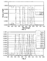
- Figure 5 depicts a detectable spectrum for each of light reflected and light transmitted by the multi-band dichroic beamsplitter of Figures 3 and 4 .
- a total of 16 independently detectable spectral bands i.e., 16 channels are achieved.
- FWHM spectral bandwidth for most chromatic epitaxial HB-LEDs is in the range of 20 to 30 nm
- the resulting 16 channels are typically each characterized by a half-band product of approximately 10 to 15 nm.
- the steep slopes and sharp knees of multi band spectral filtration, combined with the relatively narrow Gaussian wavelength distribution of epitaxial HB-LEDs advantageously maximize separation and independence of each channel.
- the present disclosure is not limited to the 8-LED/16-channel solution described above. Indeed,solution described above. Indeed, many variations are possible and may be advantageous depending on the specific application.
- Tables 1 and 2 (below) provide performance evaluations (based on BCRA ceramic color standards) for each of(i) a conventional 8-LED instrument, and (ii) an 8-LED + four-band dichroic beamsplitter instrument, respectively, as compared to a Laboratory 10 nm spectrophotometer CE7000A.
- Table 1 (Conventional 8-LED Instrument) Name DL Da Db DE White -.04 -.14 .25 .29 Lt Gray -.04 -.10 .17 .20 Mid Gray -.05 -.14 .22 .27 Diff Gray -.10 .16 -.03 .20 Dark Gray -.06 .02 -.06 .09 Pink .35 -1.43 .51 1.55 Red .38 -1.11 .33 1.22 Orange 1.78 -5.10 2.41 5.91 Yellow -.59 1.13 -2.18 2.53 Green -.68 2.72 -1.52 3.19 Diff Green -.72 2.79 -1.72 3.36 Cyan .06 -.03 .97 1.03 Dark Blue .16 -2.20 .78 2.34 avgDE 1.71 Table 2 (8-LED + Four-Band Dichroic Beamsplitter Instrument) Name DL Da Db DE White .00 -.04 .03 .05 L
- Figures 6 and 7 depict a response across the visible spectrum (400nm to 700nm) to the orange color tile for each of (i) the conventional 8-LED instrument and (ii) the 8-LED + four-band dichroic beamsplitter instrument, respectively, as compared to the Laboratory 10 nm spectrophotometer CE7000A.
- the 8-LED + four-band dichroic beamsplitter instrument exhibited improved performance, particularly between 500-600nm where eye sensitivity to hue and chroma and dE calculations of color error are most sensitive.
- the disclosed optical assemblies are not limited to such exemplary embodiments/implementations. Rather, as will be readily apparent to persons skilled in the art from the description provided herein, the disclosed optical assemblies are susceptible to modifications, alterations and enhancements without departing from the spirit or scope of the present disclosure. Accordingly, the present disclosure expressly encompasses such modification, alterations and enhancements within the scope hereof.
Abstract
Description
- The present disclosure relates to optical assemblies for spectral imaging. More particularly, the present disclosure relates to optical assemblies and methods for improving spectral resolution of a color measurement instrument.
- For many manufacturing processes, color quality control is key. Thus, expensive high precision spectrophotometers have been used to "sample" colors of both manufacturing components and finished products. Preferably, color sampling is conducted "on-line" or "on-site," i.e., in cooperation with a manufacturing process. The benefit of "on line" color sampling is two fold: (1) "on-line" color sampling advantageously enables a more comprehensive inspection of a product line; and (2) "on-line" color sampling facilitates quicker, more effective corrective action, reducing both wasted time and materials. In many instances, manufacturers also advantageously utilize handheld spectrophotometers, e.g., to facilitate mobile/user-driven color sampling.
- Due to the nature of manufacturing, "on-line" and handheld spectrophotometers are often exposed to hostile work environments, e.g., auto body shops, construction sites, etc. Thus, a clear need exists for robust inexpensive "on-line" and handheld color measurement systems that are capable of surviving and functioning in such work environments. More particularly, a need exists for "on-line" and handheld spectrophotometers that provide consistently precise color measurements irrespective of temperature variations, shock/vibrations, exposure to particulate or liquid contaminates, etc. Ideally, the sensor technology employed must be very cost effective - essentially to the point where the instrument is relatively expendable - in order to justify deployment in harsh and destructive environments. The difficulty, however, is achieving the desired robustness and cost while maintaining superior spectral resolution and accuracy.
- Existing approaches to low-cost industrial color measurement typically utilize one of two general optical configurations: (1) wide-band (i.e., white light) illumination with narrow-band sensing, and (2) narrow-band (i.e., chromatic) illumination with wide-band sensing. A common implementation of the first approach is exemplified by a pulsed xenon illumination source opposite a plurality of spectrally-filtered photodiodes. A common implementation of the second approach is exemplified by a plurality of sequentially pulsing high brightness narrow-band LEDs opposite a simple wide band sensor. The above approaches advantageously strive to increase precision by minimizing the adverse affects of ambient lighting, i.e., via using high intensity illumination and/or differential color measurement.
- In considering the above configurations, it is noted that LEDs are rapidly becoming a preferred means of illumination. LEDs are small, relatively inexpensive, energy efficient, bright and durable. Moreover, LEDs provide promising opportunities for further optimization, particularly in the areas of packaging, spectral coverage, and efficiency. LED costs have decreased dramatically and predictably as automation and economies of scale have been applied in the fabrication process. Furthermore, whereas LEDs were originally unable to generate the entire range of colors in the visual spectrum, recent material discoveries and evolutions in the manufacturing process have closed such gaps in LED spectral coverage.
- In particular, LEDs offer two distinct advantages over incandescent illumination sources. First, LEDs are capable of emitting light at specific wavelength bands, whereas incandescent light sources require association with optical filters (optical filters are costly and reduce the overall efficiency of the light source). Secondly, unlike incandescent light sources, LEDs are current-driven devices with near instantaneous response times. Thus, the current used to power an LED may be advantageously modulated, e.g., at extremely high frequencies (approximately 1 MHz). As taught in
U.S. Patent No. 6,888,633 , entitled "Color Measurement Instrument with Modulated Illumination," this capacity for frequency modulation may be exploited, e.g., to enhance both the selectivity and sensitivity of the color measurement instrument. - With regard to selectivity, frequency modulation may be used to advantageously distinguish a given light source from ambient light conditions and/or other light sources. In other words, if an LED is modulated at frequency X, the detector may be configured to respond ONLY to light modulated at frequency X. Thus, a wide-band sensor may be used to isolate and detect light originating from a specific LED and having a relatively narrow spectral output. Wide spectral coverage may be advantageously obtained, e.g., by modulating several LEDs, sequentially or concurrently, and later extracting each individual LED sub-signal from the detected signal based on a corresponding modulation "signature." Thus, a single wide-band sensor may be used to simultaneously measure a plurality of LED channels.
- With regard to sensitivity, the above described frequency modulation limits the signal of interest to one or more sub-signals having predetermined frequency(s). Detection/amplification techniques may take advantage of this property to optimize the signal-to-noise ratio for the extracted sub-signals based on the known frequency component(s) thereof (see, e.g.,
U.S. Patent No. 7,092,097 , entitled "Color Measurement Instrument," regarding improving the signal to noise ratio and overall sensitivity of an LED-based color measurement instrument using auto-zeroing at the sensor diode). Thus, whereas conventional measurements of non-modulated light are sensitive to signal processing artifacts, such as voltage offsets, stray currents, thermal drift, and random and spurious forms of electronic noise, frequency modulation enables narrow-band detection/amplification of the corresponding sub-signals which can filter, avoid, or submerge such artifacts. Accordingly, frequency modulation techniques may advantageously improve the stability of color measurements and expand the dynamic range of instrumentation based on such measurements. - Despite efforts to date, however, there remains a need for improved optical assemblies which provide greater spectral resolution in hostile work environments (greater spectral resolution enabling, e.g., detection of metameric and high chroma samples). More particularly, a need exists for improved optical assemblies that maximize the spectral resolution of a color measurement instrument, e.g., a color measurement instrument employing multi-band chromatic (LED-based) illumination. These and other needs are satisfied by optical assemblies of the present disclosure.
- The advantages of the present invention are based on the optical assembly of
claim 1. In accordance with the invention, the light providing relevant color related information can be divided before and/or after hitting a target, the color of which has to be analyzed. - Optical assemblies are provided according to the present disclosure for improving spectral resolution of a chromatic illumination-based color measurement instrument. The optical assemblies disclosed herein advantageously utilize a beamsplitting unit/apparatus in association with either (i) the illumination path or (ii) the collection path of a color measurement instrument. Selection of a preferred implementation according to the present disclosure is largely dependent on the economics involved, e.g., based on a comparison of the cost of the illumination source vs. the cost of the detector. Packaging constraints may also impact preferred implementations for a specific application. Implementations involving both the illumination path and the collection path of a color measurement instrument are discussed and claimed herein.
- Illumination path: For exemplary implementations involving the illumination path of the color measurement instrument, the beamsplitting unit/apparatus may be configured to spectrally divide one or more initial beams of light so as to emit a plurality of resultant beams of light, wherein the optical assembly is configured to illuminate a target using at least a first and a second of the plurality of resultant beams of light, and wherein each of the first and second resultant beams of light is a product of a distinct set of one or more spectral constraints exacted by the beamsplitting unit/apparatus on one of the one or more initial beams of light.
- Collection Path: For exemplary implementations involving the collection path of a color measurement instrument, the beamsplitting unit/apparatus may be configured to spectrally divide light received from a target so as to emit a plurality of resultant beams of light, wherein the optical assembly is configured to detect at least a first and a second of the plurality of resultant beams of light, and wherein each of the first and second resultant beams of light is a product of a distinct set of one or more spectral constraints exacted by the beamsplitting unit/apparatus on one of the received light.
- In either case, the first and second resultant beams of light are typically products of opposite sets of spectral-constraints exacted by the beamsplitting unit/apparatus. Thus, the first resultant beam of light may be a product of a first set of spectral constraints exacted via transmittance by the beamsplitting unit/apparatus and the second resultant beam of light may be a product of a second and opposite set of spectral constraints exacted via reflectance by the beamsplitting unit/apparatus. Generally, the beamsplitting unit/apparatus is configured to produce a plurality of resultant beams of light by dividing each spectral band of a set of one or more spectral bands characterizing either the one or more initial beams of light (for the illumination path implementation) or the received light (for the collection path implementation). Thus, the beamsplitting apparatus may include a multi-edge dichroic beamsplitter configured such that each rising and falling edge of each pass-band of the multi-band dichroic beamsplitter bisects a corresponding spectral band of the set of one or more spectral bands.
- Additional information regarding chromatic illumination can be found in
U.S. Patent Nos. 6,888,633 ,7,092,097 ,7,145,657 and7,262,853 , which are hereby incorporated by reference, in their entireties. Examples of color measurement instruments employing multi-band chromatic illumination include VeriColar™, VeriColor™ Solo and Matchstik™ instruments available from X-Rite, Inc. (Grand Rapics, MI) - As described herein, the disclosed optical assemblies may be used to effectively double the spectral resolution of a conventional chromatic illumination-based color measurement instrument. Additional features, functions and benefits of the disclosed assemblies and methods will be apparent from the description which follows, particularly when read in conjunction with the appended figures.
- To assist those of ordinary skill in the art in making and using the disclosed optical assemblies, reference is made to the appended figures, wherein:
-
Figure 1 depicts an exemplary optical assembly for a color measurement instrument, including a beamsplitting unit/apparatus in the illumination path of the color measurement instrument. -
Figure 2 depicts an exemplary optical assembly for a color measurement instrument, including a beamsplitting unit/apparatus in the collection path of the color measurement instrument. -
Figure 3 depicts an exemplary response (transmittance and reflectance) for a four-band dichroic beamsplitter. -
Figure 4 depicts configuring/tuning the four-band dichroic beamsplitter ofFigure 3 for inclusion thereof in the collection path of an 8-LED color measurement instrument. -
Figure 5 depicts a detectable spectrum for each of light reflected and light transmitted by the multi-band dichroic beamsplitter ofFigure 3 . -
Figures 6-7 depict a response across the visible spectrum (400nm to 700nm) to an orange color tile (BCRA ceramic color standard) for each of (i) a conventional 8-LED color measurement instrument, and (ii) an 8-LED + four-band dichroic beamsplitter instrument, respectively, as compared to aLaboratory 10 nm spectrophotometer CE7000A. - Referring now to
Figure 1 , an exemplaryoptical assembly 100 for a color measurement instrument is depicted, theoptical assembly 100 advantageously including a beamsplitting unit/apparatus 130 in association with an illumination path of the color measurement instrument. In general, thebeamsplitting apparatus 130 is configured to spectrally divide one or more initial beams of light so as to emit a plurality of resultant beams of light, wherein theoptical assembly 100 is configured to illuminate atarget 150 using at least a first and a second of the plurality of resultant beams of light, and wherein each of the first and second resultant beams of light is a product of a distinct set of one or more spectral constraints exacted by thebeamsplitting apparatus 130 on one of the initial beams of light. Theoptical assembly 100 may further includecollector optics 140, e.g., for collecting light reflected by or transmitted through thetarget 150 and a detector, e.g., awideband detector 120, for detecting the collected light. - As depicted in
Figure 1 , the first resultant beam of light may be the product of a first set of spectral constraints exacted on an initial beam of light via transmittance by thebeamsplitting apparatus 130. Similarly, the second resultant beam of light may be the product of a second (e.g., opposite) set of spectral constraints exacted on an initial beam of light via reflectance by thebeamsplitting apparatus 130. It is noted, however, that while, in the exemplary embodiment depicted inFigure 1 , the first and second resultant beams of light consist of light transmitted by thebeamsplitting apparatus 130 and light reflected by thebeamsplitting apparatus 130, respectively, the present disclosure is not limited to such means for spectrally dividing the one or more initial beams of light. Indeed, it is appreciated that the particular means by which thebeamsplitting apparatus 130 divides the one or more initial beams of light and emits the first and second resultant beams of light may vary (for example, a beamsplitting unit/apparatus employing a prism means for dividing the one or more initial beams of light may emit the first resultant beam at a first refraction/reflection angle and the second resultant beam at a second refraction/reflection angle). - In exemplary embodiments, the first and second resultant beams of light may be the product of first and second sets of spectral constraints exacted by the
beamsplitting apparatus 130 on first and second initial beams of light. Thus, in exemplary embodiments, theoptical assembly 100 may include first and secondchromatic illumination sources - In exemplary embodiments, the
optical assembly 100 may be configured such that the first initial beam of light (e.g., produced by the firstchromatic illumination source 110a) impinges a first side of thebeamsplitting apparatus 130 and the second initial beam of light (e.g., produced by the secondchromatic illumination source 110b) impinges a second (e.g., opposite) side of thebeamsplitting apparatus 130. Thus, the first and second initial beams of light may be oriented relative to thebeamsplitting apparatus 130 such that the first resultant beam of light (e.g., wavelengths of the first initial beam of light transmitted by the beamsplitting apparatus 130) and the second resultant beam of light (e.g., wavelengths of the second initial beam reflected/refracted by the beamsplitting apparatus 130) are directed along a same optical path, e.g., toward thetarget 150 at the desired angle of incidence relative thereto (e.g. 90°). Thus, for the exemplary embodiment depicted inFigure 1 , theoptical assembly 100 is configured such that the first initial beam of light produced by the firstchromatic illumination source 110a and the second initial beam of light produced by the secondchromatic illumination source 110b impinge opposite parallel surfaces of thebeamsplitting apparatus 130 at mirroring angles of incidence (e.g., 45°). Alternatively, thebeamsplitting apparatus 130 may be associated with an appropriate relay apparatus configured to the first and second resultant beams of light direct light originating from the single chromatic illumination source into the first and second initial beams of light toward thetarget 150 at desired angles of incidence. Again note that temporal and/or other means for distinguishing, e.g., between the first and second resultant beams are later provided herein. - With reference still to
Figure 1 , thechromatic illumination sources LEDs LEDs chromatic illumination sources LEDs LEDs chromatic illumination sources beamsplitting apparatus 130 may be associated with an appropriate relay apparatus configured to modulate/sequence, e.g., via temporal, phase and/or polarization adjustments, at least one of the first and second initial beams of light or at least one of the first and second resultant beams of light, thereby allowing for independent detection of each of the first and second resultant beams of light. - The disclosed
beamsplitting apparatus 130 may be advantageously configured to divide, e.g., bisect, trisect, etc., each spectral band of a same set of spectral bands characterizing the one or more initial beams of light, thereby producing the plurality of resultant beams of light. Thus, in exemplary embodiments, thebeamsplitting apparatus 130, may include a multi-edge dichroic beamsplitter. The multi-edge dichroic beamsplitter may be advantageously configured/tuned such that each rising and falling edge of each pass-band of the multi-band dichroic beamsplitter bisects a corresponding spectral band of the same set of spectral bands characterizing the one or more initial beams of lights. Alternatively, thebeamsplitting apparatus 130 may include a plurality of single-edge beamsplitters, e.g.,beamsplitter - Referring now to
Figure 2 , an exemplaryoptical assembly 200 for a color measurement instrument is depicted, theoptical assembly 200 advantageously including abeamsplitting apparatus 230 in association with a collection path of the color measurement instrument. In general, thebeamsplitting apparatus 230 is configured to receive light from a target (e.g., light reflected by or transmitted through atarget 250 and collected by collection optics 240) and spectrally divide the received light so as to emit a plurality of resultant beams of light, wherein theoptical assembly 200 is configured to detect, e.g., using a plurality of wide-band detectors beamsplitting apparatus 230 on the received light. - Referring to the exemplary embodiment depicted in
Figure 2 , the first resultant beam of light may be the product of a first set of spectral constraints exacted on the received light via transmission thereof through thebeamsplitting apparatus 230. Similarly, the second resultant beam of light may be the product of a second (e.g., opposite) set of spectral constraints exacted on the received light via reflection thereof by thebeamsplitting apparatus 230. It is noted, however, that while, in the exemplary embodiment depicted inFigure 2 , the first and second resultant beams of light consist of light transmitted by thebeamsplitting apparatus 230 and light reflected by thebeamsplitting apparatus 230, respectively, the present disclosure is not limited to such means for spectrally dividing the received light. Indeed, it is appreciated that the particular means by which thebeamsplitting apparatus 230 divides the received light and emits the first and second resultant beams of light may vary (for example, a beamsplitting apparatus employing a prism means for dividing the received light may emit the first resultant beam at a first refraction/reflection angle and the second resultant beam at a second refraction/reflection angle). - According to the present disclosure, the beamsplitting unit/
apparatus 230 may be advantageously configured to spectrally divide, e.g., bisect, trisect, etc., each spectral band of a set of one or more spectral bands characterizing the received light, thereby producing the plurality of resultant beams of light. Thus, in exemplary embodiments, thebeamsplitting apparatus 230, may include a multi-edge dichroic beamsplitter. The multi-edge dichroic beamsplitter may be advantageously configured/tuned such that each rising and falling edge of each pass-band of the multi-band dichroic beamsplitter divides (e.g., bisects) a corresponding spectral band of the set of spectral bands characterizing the received light. - With reference still to
Figure 2 , theoptical assembly 200 may include achromatic illumination source 210 for illuminating thetarget 250. Thechromatic illumination source 210 may include a plurality of narrow-band illuminators (e.g.,LEDs detectors - Referring now to both
Figures 1 and 2 it is noted that while the exemplaryoptical assemblies optical assemblies - Referring now to
Figure 3 , a typical multi-edge dichroic beamsplitter response (transmittance and reflectance) is depicted. As described above, a multi-edge dichroic beamsplitter may be advantageously configured/tuned such that each rising edge and each falling edge of each pass-band of the multi-band dichroic beamsplitter divides (e.g., bisects) a corresponding spectral band of a set of spectral bands characterizing light received by the beamsplitter. Thus, as depicted inFigure 4 , the multi-band dichroic beamsplitter is configured/tuned such that each rising edge and each falling edge of each pass-band bisects a spectral band corresponding to one of a plurality of narrow-band illuminators (LEDs 1-8) used to illuminate a target. -
Figure 5 , depicts a detectable spectrum for each of light reflected and light transmitted by the multi-band dichroic beamsplitter ofFigures 3 and 4 . Thus, for the 8-LED embodiment depicted, a total of 16 independently detectable spectral bands (i.e., 16 channels are achieved. Because FWHM spectral bandwidth for most chromatic epitaxial HB-LEDs is in the range of 20 to 30 nm, the resulting 16 channels are typically each characterized by a half-band product of approximately 10 to 15 nm. Notably, the steep slopes and sharp knees of multi band spectral filtration, combined with the relatively narrow Gaussian wavelength distribution of epitaxial HB-LEDs, advantageously maximize separation and independence of each channel. The present disclosure, however, is not limited to the 8-LED/16-channel solution described above. Indeed,solution described above. Indeed, many variations are possible and may be advantageous depending on the specific application. - As demonstrated below, the simple, robust, low cost, solid state solution of an 8-LED/16-channel color measurement instrument as described herein is particularly well suited for emulating a 16 point spectrophotometer. Tables 1 and 2 (below) provide performance evaluations (based on BCRA ceramic color standards) for each of(i) a conventional 8-LED instrument, and (ii) an 8-LED + four-band dichroic beamsplitter instrument, respectively, as compared to a
Laboratory 10 nm spectrophotometer CE7000A.Table 1 (Conventional 8-LED Instrument) Name DL Da Db DE White -.04 -.14 .25 .29 Lt Gray -.04 -.10 .17 .20 Mid Gray -.05 -.14 .22 .27 Diff Gray -.10 .16 -.03 .20 Dark Gray -.06 .02 -.06 .09 Pink .35 -1.43 .51 1.55 Red .38 -1.11 .33 1.22 Orange 1.78 -5.10 2.41 5.91 Yellow -.59 1.13 -2.18 2.53 Green -.68 2.72 -1.52 3.19 Diff Green -.72 2.79 -1.72 3.36 Cyan .06 -.03 .97 1.03 Dark Blue .16 -2.20 .78 2.34 avgDE 1.71 Table 2 (8-LED + Four-Band Dichroic Beamsplitter Instrument) Name DL Da Db DE White .00 -.04 .03 .05 Lt Gray .00 -.05 .02 .06 Mid Gray .00 -.05 .01 05 Diff Gray .00 -.06 .00 .06 Dark Gray .01 -.08 -.02 .08 Pink -.04 -.34 -.08 .35 Red -.07 -.55 -.14 .58 Orange -.10 -.02 .57 .58 Yellow .05 -.17 -.14 .22 Green .05 -.26 -.10 .28 Diff Green .05 -.27 -.10 .28 Dyan -.04 -.05 -.05 .08 Dark blue -.02 -.17 -.25 .30 avgDE .23 - Notably, a dramatic reduction in average and maximum color error was observed for the 8-LED + four-band dichroic beamsplitter instrument. Indeed, a 7:1 reduction in average color error was observed across the BCRA color set. Similarly, a 10:1 reduction in maximum color error was observed for the orange color tile.
-
Figures 6 and 7 depict a response across the visible spectrum (400nm to 700nm) to the orange color tile for each of (i) the conventional 8-LED instrument and (ii) the 8-LED + four-band dichroic beamsplitter instrument, respectively, as compared to theLaboratory 10 nm spectrophotometer CE7000A. Notably, the 8-LED + four-band dichroic beamsplitter instrument exhibited improved performance, particularly between 500-600nm where eye sensitivity to hue and chroma and dE calculations of color error are most sensitive. - Although the present disclosure has been described with reference to exemplary embodiments and implementations thereof, the disclosed optical assemblies are not limited to such exemplary embodiments/implementations. Rather, as will be readily apparent to persons skilled in the art from the description provided herein, the disclosed optical assemblies are susceptible to modifications, alterations and enhancements without departing from the spirit or scope of the present disclosure. Accordingly, the present disclosure expressly encompasses such modification, alterations and enhancements within the scope hereof.
Claims (15)
- An optical assembly for a color measurement instrument, said optical assembly comprising a beamsplitting apparatus in association with a path of a color measurement instrument and configured to spectrally divide light so as to emit a plurality of resultant beams of light, wherein the optical assembly is configured to use at least a first and a second of the plurality of resultant beams of light, and wherein each of the first and second resultant beams of light is a product of a distinct set of one or more spectral constraints exacted by the beamsplitting apparatus on one of the one or more initial beams of light.
- The optical assembly of claim 1, wherein the path which is in association with the beamsplitting apparatus is an illumination path of the color measurement instrument and the beamsplitting apparatus being configured to spectrally divide one or more initial beams of the light so as to emit the plurality of resultant beams of light, wherein the optical assembly is configured to illuminate a target using the at least first and second of the plurality of resultant beams of light.
- The optical assembly of claim 2, wherein the first and second resultant beams of light are products of opposite sets of spectral-constraints exacted by the beamsplitting apparatus.
- The optical assembly of one claims 1 or 3, wherein the first resultant beam of light is a product of a first set of spectral constraints exacted via transmittance by the beamsplitting apparatus and wherein the second resultant beam of light is a product of a second and opposite set of spectral constraints exacted via reflectance by the beamsplitting apparatus.
- The optical assembly of one of claims 2 to 4, wherein the first and second resultant beams of light are product of first and second sets of spectral constraints exacted by the beamsplitting apparatus on first and second initial beams of light, respectively, wherein said assembly in particular further comprising at least one of the following features a) to d):a) a first and second chromatic illumination sources for producing the first and second initial beams of light;b) each of the chromatic illuminations sources includes a spectrally identical plurality of narrow-band illuminators;c) each narrow-band illuminators in uniquely modulated and/or sequenced to facilitate independent detection of a spectral band corresponding to each narrow-band illuminator using a wide-band detector;d) the optical assembly is configured such that the first initial beam of light impinges a first side of the beamsplitting apparatus and the second initial beam of light impinges a second side of the beamsplitting apparatus and the second initial beam of light impinges a second side of the beamsplitting apparatus.
- The optical assembly of claim 5, wherein the first and second initial beams of light are oriented relative to the beamsplitting apparatus such that the first and second resultant beams of light are directed along a same optical path.
- The optical assembly of claim 6, wherein the first set of spectral constraints is exacted via transmittance by the beamsplitting apparatus and the second set of spectral constraints is exacted via reflectance by the beamsplitting apparatus and the second set of spectral constraints is exacted via reflectance by the beamsplitting apparatus and wherein the first and second initial beams of light impinge opposite parallel surfaces of the beamsplitting apparatus at mirroring angles of incidence.
- The optical assembly of one of claims 2 to 6, wherein the beamsplitting apparatus is configured to divide each spectral band of the same set of one or more spectral bands characterizing the one or more initial beams of light, thereby producing the plurality of resultant beams of light.
- The optical assembly of claim 8, wherein the beamsplitting apparatus includes a multi-edge dichroic beamsplitter configured such that each rising and falling edge of each pass-band of the multi-band dichroic beamsplitter bisects a corresponding spectral band of the same set of or more spectral bands characterizing the one or more initial beams of lights.
- The optical assembly of claim 1, wherein the path of the color measuring instrument is a collection path, wherein the assembly being configured to spectrally divide the light being received from a target so as to emit the plurality of resultant beams of light, wherein the optical assembly is configured to detect at least the first and the second of the plurality of resultant beams of light.
- The optical assembly of claim 10, wherein the first and second resultant beams of light are products of opposite sets of spectral-constraints exacted by the beamsplitting apparatus.
- The optical assembly of claim 11, wherein the first resultant beam of light is a product of a first set of spectral constraints exacted via transmittance by the beamsplitting apparatus and wherein the second resultant beam of light is a product of a second and opposite set of spectral constraints exacted via reflectance by the beamsplitting apparatus.
- The optical assembly of claim 10, wherein beamsplitting apparatus is configured to divide each spectral band of a set of one or more spectral bands characterizing the received light, thereby producing the plurality of resultant beams of light.
- The optical assembly of claim 13, herein the beamsplitting apparatus includes a multi-edge dichroic beamsplitter configured such that each rising and falling edge of each pass-band of the multi-band dichroic beamsplitter configured such that each rising and falling edge of each pass-band of the multi-band dichroic beamsplitter bisects a corresponding spectral band of the set of spectral bands characterizing the received light.
- The optical assembly of claim 14, wherein the spectral bandwidth for each of the spectral bands characterizing the received light is between 20 to 30 nm and wherein the spectral bandwidth for each spectral band characterizing the first or second resultant beams of light is between 10 to 15 nm.
Applications Claiming Priority (1)
| Application Number | Priority Date | Filing Date | Title |
|---|---|---|---|
| US12/511,603 US8199324B2 (en) | 2009-07-29 | 2009-07-29 | Optical assemblies for a color measurement instrument |
Publications (2)
| Publication Number | Publication Date |
|---|---|
| EP2284512A1 true EP2284512A1 (en) | 2011-02-16 |
| EP2284512B1 EP2284512B1 (en) | 2012-05-30 |
Family
ID=42710518
Family Applications (1)
| Application Number | Title | Priority Date | Filing Date |
|---|---|---|---|
| EP10170930A Active EP2284512B1 (en) | 2009-07-29 | 2010-07-27 | Improved optical assemblies for low cost spectral imaging with high spectral resolution |
Country Status (2)
| Country | Link |
|---|---|
| US (2) | US8199324B2 (en) |
| EP (1) | EP2284512B1 (en) |
Families Citing this family (5)
| Publication number | Priority date | Publication date | Assignee | Title |
|---|---|---|---|---|
| US8199324B2 (en) | 2009-07-29 | 2012-06-12 | X-Rite, Inc. | Optical assemblies for a color measurement instrument |
| US9189703B2 (en) | 2012-07-09 | 2015-11-17 | Canon Kabushiki Kaisha | Systems and methods for colorimetric and spectral material estimation |
| DE102013106554A1 (en) * | 2013-06-24 | 2014-12-24 | Qioptiq Photonics Gmbh & Co. Kg | Non-contact dental device |
| KR20150017961A (en) * | 2013-08-08 | 2015-02-23 | 삼성디스플레이 주식회사 | Apparatus and method for determining substrate, and manufacturing method for flexible display using the same |
| EP3035035B1 (en) | 2014-12-18 | 2020-07-22 | CLUTEX - Klastr Technické Textilie, o.s. | A method of continuous measurement of colouring of textile surfaces and a measuring machine for carrying out the method |
Citations (4)
| Publication number | Priority date | Publication date | Assignee | Title |
|---|---|---|---|---|
| DE19750756A1 (en) * | 1997-11-11 | 1999-06-02 | Soric Ind Electronic Gmbh & Co | Device to determine color of objects |
| US6888633B2 (en) | 2001-05-16 | 2005-05-03 | X-Rite, Incorporated | Color measurement instrument with modulated illumination |
| US7092097B2 (en) | 2003-09-23 | 2006-08-15 | X-Rite, Incorporated | Color measurement instrument |
| DE102005043627A1 (en) * | 2005-09-13 | 2007-03-29 | Fraunhofer-Gesellschaft zur Förderung der angewandten Forschung e.V. | Optical sensor for measuring distance and color of object, has lens detecting light reflected by surface of object, where light is focusable on receivers to detect distance dependent wavelength spectrum and spectral reflection, respectively |
Family Cites Families (6)
| Publication number | Priority date | Publication date | Assignee | Title |
|---|---|---|---|---|
| DE3626373A1 (en) * | 1986-08-05 | 1988-02-18 | Fritz Kurandt | DEVICE FOR QUICK COLOR MEASUREMENT ON DIFFERENT SAMPLES |
| US4878756A (en) * | 1988-08-08 | 1989-11-07 | Honeywell Inc. | Method and apparatus for sensing color |
| US5600487A (en) * | 1994-04-14 | 1997-02-04 | Omron Corporation | Dichroic mirror for separating/synthesizing light with a plurality of wavelengths and optical apparatus and detecting method using the same |
| US7557925B2 (en) * | 2005-08-15 | 2009-07-07 | X-Rite, Inc. | Optical instrument and parts thereof for optimally defining light pathways |
| WO2007022212A2 (en) * | 2005-08-15 | 2007-02-22 | X-Rite, Incorporated | Spectrophotometer with temperatur corrected system response |
| US8199324B2 (en) | 2009-07-29 | 2012-06-12 | X-Rite, Inc. | Optical assemblies for a color measurement instrument |
-
2009
- 2009-07-29 US US12/511,603 patent/US8199324B2/en active Active
-
2010
- 2010-07-27 EP EP10170930A patent/EP2284512B1/en active Active
-
2012
- 2012-06-07 US US13/490,858 patent/US8446585B2/en active Active
Patent Citations (6)
| Publication number | Priority date | Publication date | Assignee | Title |
|---|---|---|---|---|
| DE19750756A1 (en) * | 1997-11-11 | 1999-06-02 | Soric Ind Electronic Gmbh & Co | Device to determine color of objects |
| US6888633B2 (en) | 2001-05-16 | 2005-05-03 | X-Rite, Incorporated | Color measurement instrument with modulated illumination |
| US7092097B2 (en) | 2003-09-23 | 2006-08-15 | X-Rite, Incorporated | Color measurement instrument |
| US7145657B2 (en) | 2003-09-23 | 2006-12-05 | X-Rite, Incorporated | Color measurement instrument |
| US7262853B2 (en) | 2003-09-23 | 2007-08-28 | X-Rite, Inc. | Color measurement instrument |
| DE102005043627A1 (en) * | 2005-09-13 | 2007-03-29 | Fraunhofer-Gesellschaft zur Förderung der angewandten Forschung e.V. | Optical sensor for measuring distance and color of object, has lens detecting light reflected by surface of object, where light is focusable on receivers to detect distance dependent wavelength spectrum and spectral reflection, respectively |
Also Published As
| Publication number | Publication date |
|---|---|
| US8446585B2 (en) | 2013-05-21 |
| US8199324B2 (en) | 2012-06-12 |
| US20120274940A1 (en) | 2012-11-01 |
| EP2284512B1 (en) | 2012-05-30 |
| US20110026021A1 (en) | 2011-02-03 |
Similar Documents
| Publication | Publication Date | Title |
|---|---|---|
| US6888633B2 (en) | Color measurement instrument with modulated illumination | |
| US8233147B2 (en) | Spectrometer and a method for controlling the spectrometer | |
| US8446585B2 (en) | Optical assemblies for a color measurement instrument | |
| EP2021748B1 (en) | Spectrometer and interferometric method | |
| EP2758766B1 (en) | Infrared sensor with mutiple sources for gas measurement | |
| US7365854B2 (en) | Apparatus and methods for high speed RGB color discrimination | |
| JP3654458B2 (en) | Light source device | |
| WO2015111349A1 (en) | Multicolor-fluorescence-image analysis device | |
| US20090009761A1 (en) | Spectrophotometer and liquid chromatography system | |
| CN102246015A (en) | Monochromator comprising variable wavelength selector in combination with tunable interference filter | |
| JP6059484B2 (en) | High-resolution measuring device for substance concentration in fluid media | |
| CN107250742A (en) | Multichannel spectrophotometer and multichannel spectrophotometer data processing method | |
| JP5707739B2 (en) | Spectrometer | |
| US11199450B2 (en) | Optical sensor and method for detecting electromagnetic radiation | |
| Lou et al. | Sulfur dioxide measurements using an ultraviolet light-emitting diode in combination with gas correlation techniques | |
| CN108303387B (en) | Method and micro spectrometer for analyzing a measurement area | |
| KR100965804B1 (en) | Probe of light color analyzer using x,y,z tristimulus values | |
| US20230204510A1 (en) | Optical detector | |
| JP2005221307A (en) | Chromoscope | |
| JPH0359443A (en) | Device for spectrochemical analysis | |
| WO2022005391A1 (en) | Multi-channel interferometer-based optical sensor | |
| JP2003121361A (en) | Method and apparatus for measuring micro constituent using laser beam | |
| JPS6085339A (en) | Hue selecting device of light emitting element | |
| JPS61296237A (en) | Apparatus for discriminating oxidizing degree of copper oxide film |
Legal Events
| Date | Code | Title | Description |
|---|---|---|---|
| PUAI | Public reference made under article 153(3) epc to a published international application that has entered the european phase |
Free format text: ORIGINAL CODE: 0009012 |
|
| AK | Designated contracting states |
Kind code of ref document: A1 Designated state(s): AL AT BE BG CH CY CZ DE DK EE ES FI FR GB GR HR HU IE IS IT LI LT LU LV MC MK MT NL NO PL PT RO SE SI SK SM TR |
|
| AX | Request for extension of the european patent |
Extension state: BA ME RS |
|
| 17P | Request for examination filed |
Effective date: 20110329 |
|
| RIC1 | Information provided on ipc code assigned before grant |
Ipc: G01J 3/51 20060101ALI20111122BHEP Ipc: G01J 3/02 20060101ALI20111122BHEP Ipc: G01J 3/50 20060101AFI20111122BHEP |
|
| GRAP | Despatch of communication of intention to grant a patent |
Free format text: ORIGINAL CODE: EPIDOSNIGR1 |
|
| GRAS | Grant fee paid |
Free format text: ORIGINAL CODE: EPIDOSNIGR3 |
|
| GRAA | (expected) grant |
Free format text: ORIGINAL CODE: 0009210 |
|
| RAP1 | Party data changed (applicant data changed or rights of an application transferred) |
Owner name: X-RITE, INCORPORATED |
|
| AK | Designated contracting states |
Kind code of ref document: B1 Designated state(s): AL AT BE BG CH CY CZ DE DK EE ES FI FR GB GR HR HU IE IS IT LI LT LU LV MC MK MT NL NO PL PT RO SE SI SK SM TR |
|
| REG | Reference to a national code |
Ref country code: GB Ref legal event code: FG4D |
|
| REG | Reference to a national code |
Ref country code: CH Ref legal event code: EP |
|
| REG | Reference to a national code |
Ref country code: AT Ref legal event code: REF Ref document number: 560275 Country of ref document: AT Kind code of ref document: T Effective date: 20120615 Ref country code: CH Ref legal event code: NV Representative=s name: BOHEST AG |
|
| REG | Reference to a national code |
Ref country code: IE Ref legal event code: FG4D |
|
| REG | Reference to a national code |
Ref country code: DE Ref legal event code: R096 Ref document number: 602010001757 Country of ref document: DE Effective date: 20120726 |
|
| REG | Reference to a national code |
Ref country code: NL Ref legal event code: VDEP Effective date: 20120530 |
|
| REG | Reference to a national code |
Ref country code: LT Ref legal event code: MG4D Effective date: 20120530 |
|
| PG25 | Lapsed in a contracting state [announced via postgrant information from national office to epo] |
Ref country code: NO Free format text: LAPSE BECAUSE OF FAILURE TO SUBMIT A TRANSLATION OF THE DESCRIPTION OR TO PAY THE FEE WITHIN THE PRESCRIBED TIME-LIMIT Effective date: 20120830 Ref country code: LT Free format text: LAPSE BECAUSE OF FAILURE TO SUBMIT A TRANSLATION OF THE DESCRIPTION OR TO PAY THE FEE WITHIN THE PRESCRIBED TIME-LIMIT Effective date: 20120530 Ref country code: FI Free format text: LAPSE BECAUSE OF FAILURE TO SUBMIT A TRANSLATION OF THE DESCRIPTION OR TO PAY THE FEE WITHIN THE PRESCRIBED TIME-LIMIT Effective date: 20120530 Ref country code: IS Free format text: LAPSE BECAUSE OF FAILURE TO SUBMIT A TRANSLATION OF THE DESCRIPTION OR TO PAY THE FEE WITHIN THE PRESCRIBED TIME-LIMIT Effective date: 20120930 Ref country code: SE Free format text: LAPSE BECAUSE OF FAILURE TO SUBMIT A TRANSLATION OF THE DESCRIPTION OR TO PAY THE FEE WITHIN THE PRESCRIBED TIME-LIMIT Effective date: 20120530 Ref country code: CY Free format text: LAPSE BECAUSE OF FAILURE TO SUBMIT A TRANSLATION OF THE DESCRIPTION OR TO PAY THE FEE WITHIN THE PRESCRIBED TIME-LIMIT Effective date: 20120530 |
|
| REG | Reference to a national code |
Ref country code: AT Ref legal event code: MK05 Ref document number: 560275 Country of ref document: AT Kind code of ref document: T Effective date: 20120530 |
|
| PG25 | Lapsed in a contracting state [announced via postgrant information from national office to epo] |
Ref country code: SI Free format text: LAPSE BECAUSE OF FAILURE TO SUBMIT A TRANSLATION OF THE DESCRIPTION OR TO PAY THE FEE WITHIN THE PRESCRIBED TIME-LIMIT Effective date: 20120530 Ref country code: GR Free format text: LAPSE BECAUSE OF FAILURE TO SUBMIT A TRANSLATION OF THE DESCRIPTION OR TO PAY THE FEE WITHIN THE PRESCRIBED TIME-LIMIT Effective date: 20120831 Ref country code: LV Free format text: LAPSE BECAUSE OF FAILURE TO SUBMIT A TRANSLATION OF THE DESCRIPTION OR TO PAY THE FEE WITHIN THE PRESCRIBED TIME-LIMIT Effective date: 20120530 Ref country code: HR Free format text: LAPSE BECAUSE OF FAILURE TO SUBMIT A TRANSLATION OF THE DESCRIPTION OR TO PAY THE FEE WITHIN THE PRESCRIBED TIME-LIMIT Effective date: 20120530 |
|
| PG25 | Lapsed in a contracting state [announced via postgrant information from national office to epo] |
Ref country code: BE Free format text: LAPSE BECAUSE OF FAILURE TO SUBMIT A TRANSLATION OF THE DESCRIPTION OR TO PAY THE FEE WITHIN THE PRESCRIBED TIME-LIMIT Effective date: 20120530 |
|
| PG25 | Lapsed in a contracting state [announced via postgrant information from national office to epo] |
Ref country code: SK Free format text: LAPSE BECAUSE OF FAILURE TO SUBMIT A TRANSLATION OF THE DESCRIPTION OR TO PAY THE FEE WITHIN THE PRESCRIBED TIME-LIMIT Effective date: 20120530 Ref country code: EE Free format text: LAPSE BECAUSE OF FAILURE TO SUBMIT A TRANSLATION OF THE DESCRIPTION OR TO PAY THE FEE WITHIN THE PRESCRIBED TIME-LIMIT Effective date: 20120530 Ref country code: AT Free format text: LAPSE BECAUSE OF FAILURE TO SUBMIT A TRANSLATION OF THE DESCRIPTION OR TO PAY THE FEE WITHIN THE PRESCRIBED TIME-LIMIT Effective date: 20120530 Ref country code: DK Free format text: LAPSE BECAUSE OF FAILURE TO SUBMIT A TRANSLATION OF THE DESCRIPTION OR TO PAY THE FEE WITHIN THE PRESCRIBED TIME-LIMIT Effective date: 20120530 Ref country code: NL Free format text: LAPSE BECAUSE OF FAILURE TO SUBMIT A TRANSLATION OF THE DESCRIPTION OR TO PAY THE FEE WITHIN THE PRESCRIBED TIME-LIMIT Effective date: 20120530 Ref country code: CZ Free format text: LAPSE BECAUSE OF FAILURE TO SUBMIT A TRANSLATION OF THE DESCRIPTION OR TO PAY THE FEE WITHIN THE PRESCRIBED TIME-LIMIT Effective date: 20120530 Ref country code: RO Free format text: LAPSE BECAUSE OF FAILURE TO SUBMIT A TRANSLATION OF THE DESCRIPTION OR TO PAY THE FEE WITHIN THE PRESCRIBED TIME-LIMIT Effective date: 20120530 |
|
| PG25 | Lapsed in a contracting state [announced via postgrant information from national office to epo] |
Ref country code: PL Free format text: LAPSE BECAUSE OF FAILURE TO SUBMIT A TRANSLATION OF THE DESCRIPTION OR TO PAY THE FEE WITHIN THE PRESCRIBED TIME-LIMIT Effective date: 20120530 Ref country code: MK Free format text: LAPSE BECAUSE OF FAILURE TO SUBMIT A TRANSLATION OF THE DESCRIPTION OR TO PAY THE FEE WITHIN THE PRESCRIBED TIME-LIMIT Effective date: 20120530 Ref country code: PT Free format text: LAPSE BECAUSE OF FAILURE TO SUBMIT A TRANSLATION OF THE DESCRIPTION OR TO PAY THE FEE WITHIN THE PRESCRIBED TIME-LIMIT Effective date: 20121001 Ref country code: IT Free format text: LAPSE BECAUSE OF FAILURE TO SUBMIT A TRANSLATION OF THE DESCRIPTION OR TO PAY THE FEE WITHIN THE PRESCRIBED TIME-LIMIT Effective date: 20120530 Ref country code: MC Free format text: LAPSE BECAUSE OF NON-PAYMENT OF DUE FEES Effective date: 20120731 |
|
| PLBE | No opposition filed within time limit |
Free format text: ORIGINAL CODE: 0009261 |
|
| STAA | Information on the status of an ep patent application or granted ep patent |
Free format text: STATUS: NO OPPOSITION FILED WITHIN TIME LIMIT |
|
| REG | Reference to a national code |
Ref country code: FR Ref legal event code: ST Effective date: 20130329 |
|
| PG25 | Lapsed in a contracting state [announced via postgrant information from national office to epo] |
Ref country code: ES Free format text: LAPSE BECAUSE OF FAILURE TO SUBMIT A TRANSLATION OF THE DESCRIPTION OR TO PAY THE FEE WITHIN THE PRESCRIBED TIME-LIMIT Effective date: 20120910 Ref country code: FR Free format text: LAPSE BECAUSE OF NON-PAYMENT OF DUE FEES Effective date: 20120731 |
|
| 26N | No opposition filed |
Effective date: 20130301 |
|
| REG | Reference to a national code |
Ref country code: IE Ref legal event code: MM4A |
|
| REG | Reference to a national code |
Ref country code: DE Ref legal event code: R097 Ref document number: 602010001757 Country of ref document: DE Effective date: 20130301 |
|
| PG25 | Lapsed in a contracting state [announced via postgrant information from national office to epo] |
Ref country code: IE Free format text: LAPSE BECAUSE OF NON-PAYMENT OF DUE FEES Effective date: 20120727 Ref country code: MT Free format text: LAPSE BECAUSE OF FAILURE TO SUBMIT A TRANSLATION OF THE DESCRIPTION OR TO PAY THE FEE WITHIN THE PRESCRIBED TIME-LIMIT Effective date: 20120530 Ref country code: BG Free format text: LAPSE BECAUSE OF FAILURE TO SUBMIT A TRANSLATION OF THE DESCRIPTION OR TO PAY THE FEE WITHIN THE PRESCRIBED TIME-LIMIT Effective date: 20120830 |
|
| PG25 | Lapsed in a contracting state [announced via postgrant information from national office to epo] |
Ref country code: AL Free format text: LAPSE BECAUSE OF FAILURE TO SUBMIT A TRANSLATION OF THE DESCRIPTION OR TO PAY THE FEE WITHIN THE PRESCRIBED TIME-LIMIT Effective date: 20120530 |
|
| PG25 | Lapsed in a contracting state [announced via postgrant information from national office to epo] |
Ref country code: TR Free format text: LAPSE BECAUSE OF FAILURE TO SUBMIT A TRANSLATION OF THE DESCRIPTION OR TO PAY THE FEE WITHIN THE PRESCRIBED TIME-LIMIT Effective date: 20120530 |
|
| PG25 | Lapsed in a contracting state [announced via postgrant information from national office to epo] |
Ref country code: LU Free format text: LAPSE BECAUSE OF NON-PAYMENT OF DUE FEES Effective date: 20120727 Ref country code: SM Free format text: LAPSE BECAUSE OF FAILURE TO SUBMIT A TRANSLATION OF THE DESCRIPTION OR TO PAY THE FEE WITHIN THE PRESCRIBED TIME-LIMIT Effective date: 20120530 |
|
| PG25 | Lapsed in a contracting state [announced via postgrant information from national office to epo] |
Ref country code: HU Free format text: LAPSE BECAUSE OF FAILURE TO SUBMIT A TRANSLATION OF THE DESCRIPTION OR TO PAY THE FEE WITHIN THE PRESCRIBED TIME-LIMIT Effective date: 20100727 |
|
| PGFP | Annual fee paid to national office [announced via postgrant information from national office to epo] |
Ref country code: GB Payment date: 20230608 Year of fee payment: 14 Ref country code: CH Payment date: 20230801 Year of fee payment: 14 |
|
| PGFP | Annual fee paid to national office [announced via postgrant information from national office to epo] |
Ref country code: DE Payment date: 20230531 Year of fee payment: 14 |