EP2287549A2 - Heating/cooling system for indwelling heat exchange catheter - Google Patents
Heating/cooling system for indwelling heat exchange catheter Download PDFInfo
- Publication number
- EP2287549A2 EP2287549A2 EP10188614A EP10188614A EP2287549A2 EP 2287549 A2 EP2287549 A2 EP 2287549A2 EP 10188614 A EP10188614 A EP 10188614A EP 10188614 A EP10188614 A EP 10188614A EP 2287549 A2 EP2287549 A2 EP 2287549A2
- Authority
- EP
- European Patent Office
- Prior art keywords
- pump
- bath
- saline
- temperature
- heat exchange
- Prior art date
- Legal status (The legal status is an assumption and is not a legal conclusion. Google has not performed a legal analysis and makes no representation as to the accuracy of the status listed.)
- Granted
Links
Images


Classifications
-
- F—MECHANICAL ENGINEERING; LIGHTING; HEATING; WEAPONS; BLASTING
- F25—REFRIGERATION OR COOLING; COMBINED HEATING AND REFRIGERATION SYSTEMS; HEAT PUMP SYSTEMS; MANUFACTURE OR STORAGE OF ICE; LIQUEFACTION SOLIDIFICATION OF GASES
- F25D—REFRIGERATORS; COLD ROOMS; ICE-BOXES; COOLING OR FREEZING APPARATUS NOT OTHERWISE PROVIDED FOR
- F25D17/00—Arrangements for circulating cooling fluids; Arrangements for circulating gas, e.g. air, within refrigerated spaces
- F25D17/02—Arrangements for circulating cooling fluids; Arrangements for circulating gas, e.g. air, within refrigerated spaces for circulating liquids, e.g. brine
-
- A—HUMAN NECESSITIES
- A61—MEDICAL OR VETERINARY SCIENCE; HYGIENE
- A61F—FILTERS IMPLANTABLE INTO BLOOD VESSELS; PROSTHESES; DEVICES PROVIDING PATENCY TO, OR PREVENTING COLLAPSING OF, TUBULAR STRUCTURES OF THE BODY, e.g. STENTS; ORTHOPAEDIC, NURSING OR CONTRACEPTIVE DEVICES; FOMENTATION; TREATMENT OR PROTECTION OF EYES OR EARS; BANDAGES, DRESSINGS OR ABSORBENT PADS; FIRST-AID KITS
- A61F7/00—Heating or cooling appliances for medical or therapeutic treatment of the human body
- A61F7/0085—Devices for generating hot or cold treatment fluids
-
- A—HUMAN NECESSITIES
- A61—MEDICAL OR VETERINARY SCIENCE; HYGIENE
- A61F—FILTERS IMPLANTABLE INTO BLOOD VESSELS; PROSTHESES; DEVICES PROVIDING PATENCY TO, OR PREVENTING COLLAPSING OF, TUBULAR STRUCTURES OF THE BODY, e.g. STENTS; ORTHOPAEDIC, NURSING OR CONTRACEPTIVE DEVICES; FOMENTATION; TREATMENT OR PROTECTION OF EYES OR EARS; BANDAGES, DRESSINGS OR ABSORBENT PADS; FIRST-AID KITS
- A61F7/00—Heating or cooling appliances for medical or therapeutic treatment of the human body
- A61F7/12—Devices for heating or cooling internal body cavities
- A61F2007/126—Devices for heating or cooling internal body cavities for invasive application, e.g. for introducing into blood vessels
-
- F—MECHANICAL ENGINEERING; LIGHTING; HEATING; WEAPONS; BLASTING
- F25—REFRIGERATION OR COOLING; COMBINED HEATING AND REFRIGERATION SYSTEMS; HEAT PUMP SYSTEMS; MANUFACTURE OR STORAGE OF ICE; LIQUEFACTION SOLIDIFICATION OF GASES
- F25B—REFRIGERATION MACHINES, PLANTS OR SYSTEMS; COMBINED HEATING AND REFRIGERATION SYSTEMS; HEAT PUMP SYSTEMS
- F25B2400/00—General features or devices for refrigeration machines, plants or systems, combined heating and refrigeration systems or heat-pump systems, i.e. not limited to a particular subgroup of F25B
- F25B2400/01—Heaters
-
- F—MECHANICAL ENGINEERING; LIGHTING; HEATING; WEAPONS; BLASTING
- F25—REFRIGERATION OR COOLING; COMBINED HEATING AND REFRIGERATION SYSTEMS; HEAT PUMP SYSTEMS; MANUFACTURE OR STORAGE OF ICE; LIQUEFACTION SOLIDIFICATION OF GASES
- F25B—REFRIGERATION MACHINES, PLANTS OR SYSTEMS; COMBINED HEATING AND REFRIGERATION SYSTEMS; HEAT PUMP SYSTEMS
- F25B2600/00—Control issues
- F25B2600/02—Compressor control
- F25B2600/025—Compressor control by controlling speed
- F25B2600/0253—Compressor control by controlling speed with variable speed
-
- F—MECHANICAL ENGINEERING; LIGHTING; HEATING; WEAPONS; BLASTING
- F25—REFRIGERATION OR COOLING; COMBINED HEATING AND REFRIGERATION SYSTEMS; HEAT PUMP SYSTEMS; MANUFACTURE OR STORAGE OF ICE; LIQUEFACTION SOLIDIFICATION OF GASES
- F25B—REFRIGERATION MACHINES, PLANTS OR SYSTEMS; COMBINED HEATING AND REFRIGERATION SYSTEMS; HEAT PUMP SYSTEMS
- F25B2700/00—Sensing or detecting of parameters; Sensors therefor
- F25B2700/13—Mass flow of refrigerants
- F25B2700/135—Mass flow of refrigerants through the evaporator
- F25B2700/1351—Mass flow of refrigerants through the evaporator of the cooled fluid upstream or downstream of the evaporator
Definitions
- the present invention relates generally to methods and apparatus for exchanging heat with the body of a patient.
- the above-mentioned advantages in regulating temperature can be realized by cooling or heating the patient's entire body.
- the present invention understands that since many patients already are intubated with central venous catheters for other clinically approved purposes anyway such as drug delivery and blood monitoring, providing a central venous catheter that can also cool or heat the blood requires no additional surgical procedures for those patients.
- single purpose heat exchange catheters such as are made by Innercool Therapies of San Diego, CA and Radiant Medical of Portola Valley, CA can also be less optimally used.
- a heat exchange system for an indwelling heat exchange catheter includes a heat exchange bath that is configured to receive a conduit that carries working fluid to and from the catheter.
- a heating/coolant fluid is disposed within the bath to exchange heat with the working fluid.
- the heating/coolant fluid flows through a heat exchanger that includes a refrigerant and two or more compressors that are connected in parallel to each other.
- a heating/coolant fluid pump circulates the heating/coolant fluid between the heat exchanger and the heat exchange bath.
- the compressors are variable speed direct current (DC) compressors.
- a positive displacement gear pump preferably pumps the working fluid, e.g., saline, to and from the catheter.
- the pump is removably engaged with a motor.
- a heat exchange system for an indwelling heat exchange catheter includes a heat exchange bath that is configured to receive a conduit that carries working fluid to and from the catheter.
- a pump communicates with the conduit and pumps the working fluid to and from the catheter.
- a fluid pump assembly in yet another aspect of the present invention, includes a pump support platform.
- a pump is removably engaged with the pump support platform.
- the pump pumps working fluid to and from an intravascular catheter.
- a heat exchange system for an indwelling heat exchange catheter includes a heat exchange bath that is configured to receive a conduit that carries working fluid to and from the catheter.
- a flow detector communicates with the conduit and detects when working fluid is flowing through the conduit.
- a fluid flow detector in yet still another aspect of the present invention, includes a clear housing and a paddle wheel that is rotatably disposed within the housing.
- the fluid flow detector further includes three infrared transmitter/receiver light emitting diode pairs. Each infrared transmitter/receiver light emitting diode pair establishes a signal path through the housing.
- a patient heating/cooling system is shown and generally designated 10.
- the system 10 includes three separate fluid circuits: a saline circuit (also referred to as the working fluid circuit), a water glycol circuit (also referred to as' the heating/cooling fluid circuit), and a refrigerant circuit (also referred to as the refrigerating fluid circuit.)
- a saline circuit also referred to as the working fluid circuit
- a water glycol circuit also referred to as' the heating/cooling fluid circuit
- refrigerant circuit also referred to as the refrigerating fluid circuit.
- an indwelling heat exchange catheter 12 that can be inserted into a patient 13 during an operation is connected to a heat exchange bath 14 by a saline supply line 16.
- the supply line 16 is connected to a coiled or helical heat exchange tube 17 that is immersed in the bath 14 fluid to exchange heat therewith.
- the heat exchange tube 17 is connected to a peristaltic tubing saline pump 18 by fluid line 20.
- the saline pump 18 draws saline from a saline reservoir 22 via fluid line 24.
- the saline reservoir 22 is disposed within a saline level detector 25 that, as described in detail below, helps control the saline pump 18 based on the level of saline in the level reservoir 22.
- the saline pump 18 has four modes: a standby or off mode, two treatment modes (i.e., two treatment speeds), and an idle mode wherein the saline pump 18 operates very slowly, but does not stop. In the idle mode, the patient 13 is effectively thermally decoupled from the heating/cooling system 10.
- a saline source 26 provides saline to the saline reservoir 22 via fluid line 28.
- the saline source 26 is an intravenous (IV) bag and a line clamp 27 is installed on fluid line 28 between the saline source 26 and the saline reservoir 22. It is to be understood that after the saline reservoir 22 is filled the line clamp 27 is clamped on fluid line 28 to isolate the saline source 26 from the saline reservoir 22.
- Figure 1 shows a saline return line 29 communicates saline from the catheter 12 to the saline reservoir 22 to complete the saline circuit. It is to be appreciated that the tubes 16, 17, 20, 24, and 29 can be provided as a disposable IV tubing set.
- Figure 1 also shows a system controller 30 that is connected to the saline level detector 25 via electrical line 32 and electrical line 34, i.e., one for each infrared detector that is associated with the saline level detector 25 as described below.
- the system controller 30 is also connected to a safety switch 36 of the saline pump 18 via electrical line 38.
- the system controller 30 receives signals from the saline level detector 25 regarding the level of saline therein and uses this information to control the saline pump 18, including opening the safety switch 36 to de-energize the saline pump 18 under certain low saline level conditions.
- saline is circulated to and from the catheter 12 through the helical heat exchange tube 17 in the heat exchange bath 14.
- the heat exchange bath 14 is filled with heating/cooling fluid, preferably water glycol.
- the water glycol can be heated or cooled in order to heat or cool the saline and thus, increase or decrease the temperature of the patient 13 into which the catheter 12 is inserted.
- the preferred working fluid is saline, but any similar fluid well known in the art can be used.
- the water glycol circuit communicates with a chiller/heater 40 via a water glycol supply line 42 and a water glycol return line 44.
- a water glycol pump 46 is installed in the water glycol return line 44 to circulate water glycol through the water glycol circuit.
- Figure 1 shows that the heat exchange bath 14 is also in fluid communication with a water glycol reservoir 47 installed within a water glycol level detector 48 via fluid line 50.
- the water glycol level detector 48 is used to determine the level of water glycol within the heat exchange bath 14.
- system controller 30 is connected to the chiller/heater 40 via electrical lines 52 and 54. Moreover, the system controller 30 is connected to a safety switch 55 at the water glycol pump 46 via electrical line 56 and to the coolant level detector 48 via electrical line 58 and electrical line 60. Thus, the system controller 30 can control the operation of the chiller/heater 40 based on signals from a temperature monitor, described below, and control the operation of the water glycol pump 46 based on level signals from infrared detectors, also described below, that are disposed within the water glycol level detector 48. As shown, the system controller 300 is also connected to a temperature sensor 57 placed at the outlet of the chiller/heater via electrical line 59. The controller 30 uses input from the temperature sensor 57 to control the chiller/heater 40 and other system 10 components.
- the chiller/heater 40 can heat or cool the water glycol.
- the water glycol exchanges heat with the saline.
- the water glycol can be used to heat or cool saline and in turn, heat or cool the patient in which the catheter 12 is intubated.
- water glycol is the preferred heating/cooling fluid. However, any other fluid with similar properties can be used.
- a variable speed direct current (DC) compressor 62 is in fluid communication with the chiller/heater 40 via a refrigerant supply line 64 and a refrigerant return line 66. It is to be understood that the compressor 62 is filled with refrigerant, e.g., R134a.
- a compressor controller 68 is connected to the compressor 62 via an electrical line 70.
- the system controller 30 is connected to the compressor controller 68 via electrical line 72.
- the compressor controller 68 is also connected to a heater, described below, within the chiller/heater 40 via electrical line 73.
- the system controller 30 receives temperature signals from the temperature monitor, described below, and uses these signals to control the operation of the compressor 62 and the heater.
- the compressor 62 is used to cool the water glycol that is pumped through the chiller/heater 40 by the water glycol pump 46.
- a DC power supply 74 is connected to the system controller 30 by an electrical line 76.
- the DC power supply 74 preferably is connected to' an isolation transformer (XFMR) 78 by electrical line 80.
- the XFMR 78 can be connected to an alternating current (AC) input 82, e.g., a standard one hundred and twenty volt (120V) wall outlet, via a power cord 84.
- the system 10 can also be configured to work accommodate one hundred to two hundred and forty volts AC (100 - 240 VAC).
- a temperature monitor 86 is connected to the system controller 30 via an electrical line 88.
- a first patient temperature probe 90 and a second patient temperature probe 92 preferably are connected to the temperature monitor 86 via electrical lines 94 and 96, respectively.
- the temperature monitor 86 uses the temperature probes 90, 92 to monitor the temperature of the patient 13.
- the temperature monitor 86 sends signals to the system controller 30 representing the temperature of the patient 13. These signals are used by the system controller 30 to control the operation of the chiller/heater 40, the saline pump 18, and the DC compressor 62.
- Figure 1 shows a display device 98 that is connected to the system controller 30 via electrical line 100 and electrical line 102.
- the display device 98 provides a visual indication of the patient's temperature and the bath temperature.
- the display device 98 can be used to output graphs of minute by minute patient temperature (for, e.g., twenty one days) and water glycol bath temperature the display device 98 can also be used to provide information regarding the cooling power required by the patient, whether the system is heating or cooling the bath, and at which rate, e.g., low, medium, or maximum, the system is heating or cooling the bath.
- the display device 98 can display the current patient temperature and the patient target temperature.
- the display device 98 also includes a control panel 104 to allow a user, i.e., a doctor or a nurse, to input data, such as a target patient temperature, to the system 10.
- the preferred heat exchange bath 14 includes a bottom 110 having a generally cylindrical continuous sidewall 112 extending therefrom. As shown, the bottom 110 of the bath 14 is formed with a hole 114 and the water glycol supply line 42 is connected thereto. A preferably vertical standpipe 116 extends from the end of the water glycol supply line 42 into the interior of the bath 14. In a preferred embodiment, the standpipe 116 is perforated along its length with a series of four hole rings 118 out of which water glycol flows into the bath 14. These four hole rings 118 ensure radial movement of the water glycol through the heat exchange tubing 17, i.e., between and across the turns of the coil. It can be appreciated that in lieu of the standpipe 116, a small impeller (not shown) can be mounted on the bottom 110 of the bath 14 to circulate the water glycol therein.
- a small impeller (not shown) can be mounted on the bottom 110 of the bath 14 to circulate the water glycol therein.
- the generally spiral-shaped heat exchange tubing 17 is disposed within the bath 14 such that when the bath 14 is filled with water glycol the heat exchange tubing 17 is fully immersed in the water glycol.
- Figure 2 shows that the saline supply line 16 is connected to one end of the heat exchange tubing 17.
- the fluid line 20 from the saline pump 18 is connected to the other end of the heat exchange tubing 17.
- four vertical stanchions 122 extend up from the bottom 110 of the bath 14 and touch the outer surface of the tubing set 120.
- the heat exchange tubing 17 can rest against the sidewall 112 of the bath 14.
- FIG. 2 further shows that the bath 14 is covered by a lid 124.
- the bottom of the lid 124 is spaced above the top of the water glycol within the bath 14 in order to establish a dead air space 126 between the lid 124 and the water glycol.
- This dead air space 126 acts as an insulator to minimize parasitic heat loads, control the evaporation of the water glycol, and prevent progressive overfilling of the bath 14 by condensation from the ambient air.
- the lid 124 can be sealed against the wall 112 by a resilient, preferably silicone, gasket 128.
- the saline level detector 25 includes a housing 130 that is preferably made from acetal, e.g., Delrin® manufactured by E.I. Dupont De Nemours & Co. of Delaware.
- the housing 130 is formed with a preferably "U" shaped central bore 132 in which the preferably clear saline reservoir 22 is disposed.
- Figure 3 shows that the housing is formed with a first transverse bore 134, a second transverse bore 136, and a third transverse bore 138 leading to the central bore 132.
- the saline level detector 25 includes a light emitter, e.g., an infrared light emitting diode (IR LED) 140, that is mounted in the first bore 134 on one side of the level detector 22.
- IR LED infrared light emitting diode
- two light detectors such as a first IR detector 142 and a second IR detector 144, are placed on the opposite side of the saline level detector 25 from the LED 140 within the second and third transverse bores 136, 138.
- the detectors 142, 144 are photodiodes or phototransistors.
- IR LED 140 and the IR detectors 142, 144 are coplanar.
- the IR LED 140 emits an IR light beam that can be detected by the first IR detector 142 if the saline level is below a predetermined level, e.g., the level of the IR LED 140 and the IR detectors 142, 144.
- a predetermined level e.g., the level of the IR LED 140 and the IR detectors 142, 144.
- the saline is low, the IR light beam takes the path toward the first IR detector 142 as indicated by the dashed line 146.
- the IR light beam is refracted so that it is detected by the second IR detector 144. In this case, the IR light beam takes the path indicated by line 148.
- the IR light beam can be modulated, i.e. pulsed, e.g., at nine and a half kiloHertz (9.5 kHz), to avoid false detections caused, e.g., by other light sources placed in the same room as the level detector 25 and/or bubbles in the saline reservoir 22.
- the first IR detector 142 and second IR detector 144 can be connected to upper and lower tone detectors 150, 152, respectively, which output signals only when they receive an input of, e.g., 9.5 kHz. It can be appreciated that when the saline level within the level detector falls below a predetermined level, the controller 30 can activate an alarm at the display device 98.
- the alarm can include a visible alarm, e.g., a light, or an audible alarm, e.g., a buzzer.
- a visible alarm e.g., a light
- an audible alarm e.g., a buzzer.
- the controller 30 can de-energize the saline pump 18 by opening the safety switch 36.
- FIG. 4 shows the details regarding one preferred, non-limiting implementation of the chiller/heater 40.
- the chiller/heater 40 is a shell-and-tube heat exchanger having a lower chamber 160, an upper chamber 162, and plural tubes 164 communicating water glycol therebetween. It is to be understood that water glycol flows into the lower chamber 160, up the tubes 164, into to the upper chamber 162, and out of the upper chamber 162 to the heat exchange bath 14. Refrigerant, e.g., R134a, flows around the tubes 164 to cool the water glycol therein.
- a resistive heater element 166 is disposed in the lower chamber 160 and extends partially up an enlarged center tube 168 for heating the water glycol in the chiller/heater 60.
- the heater element 166 can include a built-in thermocouple temperature sensor 170 that can be used as described in detail below to determine if glycol is flowing through the chiller/heater 60. It is to be appreciated that in a less preferred embodiment the chiller/heater 40 and the heat exchange bath 14 can be combined into a single unit. Moreover, it is to be appreciated that the temperature sensor 170 can be connected to the system controller.
- T pt the patient temperature
- T target the patient target temperature
- T bath the bath temperature
- T pt is received from the temperature monitor 86, specifically from the second temperature probe 92.
- ⁇ T a temperature differential, ⁇ T, is determined by subtracting T pt from T target
- decision diamond 204 it is determined whether the absolute value of ⁇ T is less than a predetermined amount, e.g., one tenth of a degree Celsius (0.1 °C).
- the logic moves to block 206 where the system 10 enters maximum cooling mode or maximum warming mode. It is to be understood that if ⁇ T is negative the saline pump 18 is brought to full speed, the compressor 62 is turned on at high speed, and the heater 166 is turned off to cool the patient. Conversely, if ⁇ T is positive, the saline pump 18 is brought to full speed, the compressor 62 is turned off, and the heater 166 is turned on to warm the patient.
- the logic moves to decision diamond 210 where it is determined whether the absolute value of dT pt /dt is greater than thirty six hundredths of a degree Celsius per hour (0.36 °C/hr). If not, the logic continues to block 212 and a new T bath is determined. The new T bath is determined based on the rate of change of patient temperature.
- the logic proceeds to block 216, wherein the compressor 62 and chiller/heater 40 are operated in accordance with the rules set forth below to achieve the new T bath Continuing to block 218, in a preferred embodiment, the saline pump 18 is selectively idled per the following rules:
- Figure 6 shows the linear mode operation logic of the present invention.
- a do loop is entered wherein while in the linear mode, the succeeding steps are performed.
- several "fail safe" tests are monitored for to revert to maximum cooling or heating in the event that a rapid patient temperature change occurs. For instance, at decision diamond 232, if it is determined that ⁇ T is greater than one half a degree Celsius (0.5 °C) and has a negative sign, the system exits linear mode and enters maximum cooling mode at block 234.
- ⁇ T is positive and greater than three tenths of a degree Celsius (0.3 °C)
- the logic moves to block 238 where the linear mode is exited and the maximum warming mode is entered.
- dT pt /dt is determined using the equation described above.
- dT pt /dt is greater than seven tenths of a degree Celsius per hour (0.7 °C/hr) for the last ten (10) minutes. If so, the logic moves to block 234 where the linear mode is exited and the maximum cooling mode is entered. If dT pt /dt is less than 0.7 °C/hr for the last 10 minutes, the logic returns to decision diamond 232 and continues as described above.
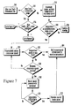
- the control logic of the compressor commences at block 250 with a do loop, wherein after a new T bath is determined, the following steps are performed.
- decision diamond 252 it is determined whether the new T bath is greater than the current T bath . If the new T bath is lower than the current T bath , the logic moves to block 254 and the heater 166 is deactivated while the compressor 62 is activated at maximum speed to cool the water glycol.
- decision diamond 256 it is determined whether the current bath temperature is within a predetermined range, e.g., two-tenths degrees Celsius (0.2 °C) of the new T bath . If not, the logic moves to block 258 where the cooling of the water glycol is continued. The logic then returns to decision diamond 256. If the current bath temperature is within the predetermined range of the new T bath , the logic moves to block 260 wherein the compressor speed is progressively reduced.
- a predetermined range e.g., two-tenths degrees Celsius (0.2 °C) of the new T bath .
- the logic moves to decision diamond 262 where it is determined whether the current temperature is stable at the new T bath . If so, the logic moves to block 264 and the compressor 62 is held at the current speed to maintain the temperature at the new T bath . If, at decision diamond 262, the temperature has not stabilized at the new T bath , the logic moves to decision diamond 266 where it is determined whether the minimum compressor speed has been reached. If the minimum compressor speed has not been reached, the logic returns to block 260 and continues as described above. Conversely, if the minimum compressor speed has been reached, the logic moves to block 268 where the heater power is progressively increased.
- the logic continues to decision diamond 270 where it is determined if the current temperature has stabilized at the new T bath . If not, the logic returns to block 268 where the heater power continues to be progressively increased. If, on the other hand, the current temperature has stabilized at T bath the logic moves to block 272 where the current power is maintained. Thereafter, the logic moves to block 264 where the compressor is idled at the current speed, in this case the lowest speed, in order to maintain the temperature at T bath . In a preferred, non-limiting embodiment, the lowest temperature to which the bath can be commanded is one-half degree Celsius (0.5 °C).
- the logic proceeds to decision diamond 274 where it is determined whether the new T bath is less than or equal to a predetermined upper bath limit, e.g., forty two degrees Celsius (42 °C). If the new T bath is less than the upper bath limit, the logic moves to Figure 8 . However, if the new T bath is equal to the upper bath limit, the logic moves to Figure 9 .
- a predetermined upper bath limit e.g., forty two degrees Celsius (42 °C).
- the logic proceeds to block 276 where the compressor 62 is activated at minimum speed and the heater 166 is activated at maximum power. From block 276, the logic moves to decision diamond 278 where it is determined if the current temperature is within a predetermined range, e.g., two-tenths degrees Celsius (0.2 °C) of the new T bath . If not, the logic proceeds to block 280 and the heating of the water glycol is continued. If the temperature is within the predetermined range, the logic continues to block 282 where the heater power is progressively reduced.
- a predetermined range e.g., two-tenths degrees Celsius (0.2 °C)
- decision diamond 284 it is determined whether the current temperature has stabilized at the new T bath . If the current temperature has stabilized at the new T bath , the current heater power is maintained to maintain the temperature at the new T bath . On the other hand, if the current temperature has not stabilized, the logic proceeds to decision diamond 288 where it is determined if the heater duty cycle is equal to zero (0). If not, the logic returns to block 282 where the progressive reduction of the heater power is continued.
- the logic moves to Figure 9 .
- the compressor is deactivated and the heater is activated at maximum power.
- the logic moves to decision diamond 298 where it is determined whether the temperature is within a predetermined range, e.g., two-tenths degrees Celsius (0.2 °C), of the new T bath , If not, the heating of the water glycol is continued at block 300. If the current temperature is within 3 °C of the new T bath , the logic proceeds to block 302 where the power of the heater 166 is progressively reduced.
- decision diamond 304 it is determined whether the temperature has stabilized at the new T bath , If so, the current heater power is maintained to maintain the temperature at the new T bath . Conversely, if the temperature has not stabilized at the new T bath, the logic continues to decision diamond 308 where it is determined whether the heater duty cycle has reached zero (0). If the heater duty cycle has not reached zero, the logic returns to block 302 where the progressive reduction of the heater power is continued. On the other hand, if the heater duty cycle has reached zero, the compressor 62 is briefly cycled in order to cool the water glycol. Next, at decision diamond 312, it is again determined whether the temperature has stabilized at the new T bath . If not, the logic returns to block 310 and the compressor is again briefly cycled to cool the water glycol. If, at decision diamond 312, the temperature has stabilized at the new T bath , the logic moves to block 306 and ends.
- the system described above has two nested closed-loop controllers: an outer loop and an inner loop.
- the outer loop is directly responsible for controlling the patient temperature and is driven by the temperature difference between T target and T pt .
- the inner loop is directly responsible for the coolant temperature, i.e., T bath , that is established by the system controller 30.
- the outer loop logic i.e., the overall operation logic and linear mode operation logic describe above, resides in the system controller 30.
- the inner loop control logic i.e., the compressor control logic described above, resides in the compressor controller 68.
- the compressor controller 68 controls the compressor 62 and the heater 166, as described above, in order to achieve the new T bath .
- the compressor controller 68 has two means of control over the compressor 62. First, it can turn the power to compressor 62 on and off via a solid-state DC relay. Second, it can modulate the compressor speed between a maximum value, e.g., thirty five hundred revolutions per minute (3,500 RPM), and a minimum value, e.g., two thousand revolutions per minute (2,000 RPM).
- a maximum value e.g., thirty five hundred revolutions per minute (3,500 RPM)
- a minimum value e.g., two thousand revolutions per minute (2,000 RPM).
- the compressor controller 68 has only duty-cycle control over the heater 166.
- the compressor controller 68 can modulate the heater power anywhere between zero percent (0 %), i.e., off, and one hundred percent (100 %), i.e., on.
- the heater 166 has a fixed one second (1 s) pulse period.
- the heater 166 has a maximum power of two hundred and forty watts (240 w).
- a fifty percent (50 %) duty cycle corresponds to one hundred and twenty watts (120 w) of time-averaged input power to the water glycol and a twenty five percent (25 %) duty cycle would correspond to sixty watts (60 w) of time-averaged input power.
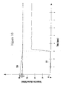
- FIG 10 shows one exemplary, non-limiting graph of T pt , represented by line 320, and T bath , represented by line 322, plotted versus time.
- the patient is initially in a hyperthermic state, i.e., the patient has a fever of thirty-nine degrees Celsius (39 °C).
- the patient is cooled from 39 °C toward a T target equal to thirty-six and one-half degrees Celsius (36.5 °C) preferably over a three hour period at a rate of eight tenths of a degree Celsius per hour (0.80 °C/hr). This can be achieved by entering a maximum cooling mode where the T bath is one-half a degree Celsius (0.5 °C).
- the saline pump 18 preferably is idled to thermally de-couple the patient 13 from the cooling system 10 and the T bath is increased, e.g., by energizing the heater 166, to approximately twenty-five degrees Celsius (25 °C).
- T pt will discontinue the rapid decrease described above while T bath is increased.
- the saline pump 18 is returned to full speed to thermally couple the patient 13 to the cooling system 20.
- the higher T bath slows the rate at which the patient 13 is cooled and helps to maintain T pt in a state of equilibrium near T target , e.g., within one-tenth of a degree Celsius (0.1 °C) of T target .
- T bath can be slightly increased or decreased, e.g., less than five degrees Celsius (5 °C), as shown in order to maintain T pt in the state of equilibrium described above.
- FIG. 11 an alternative patient heating/cooling system is shown and generally designated 410. Similar to the above-described system 10, the system 410 shown in Figure 11 includes three separate fluid circuits: a saline circuit (also referred to as the working fluid circuit), a water glycol circuit (also referred to as the heating/cooling fluid circuit), and a refrigerant circuit (also referred to as the refrigerating fluid circuit.)
- a saline circuit also referred to as the working fluid circuit
- a water glycol circuit also referred to as the heating/cooling fluid circuit
- refrigerant circuit also referred to as the refrigerating fluid circuit.
- an indwelling heat exchange catheter 412 that can be inserted into a patient 413 during an operation is connected to a heat exchange bath 414 by a saline supply line 416.
- the supply line 416 is connected to a coiled or helical heat exchange tube 417 that is immersed in the bath fluid to exchange heat therewith.
- the heat exchange tube 417 is connected an air trap vessel 418 by fluid line 420.
- the air trap vessel 418 is surrounded by an air trap detector 419. As shown, the air trap vessel 418 is connected to a saline pump 422 by fluid line 424.
- the air trap detector 419 is identical in construction to the saline level detector 25 described above and shown in Figure 3 and can be used to detect when air is introduced into the working fluid circuit downstream from the pump 422, e.g., by the pump 422 itself. Accordingly, if air is detected in the air trap vessel 418, the pump 422 is immediately shut down by a controller in accordance with the principles discussed earlier.
- a saline source 426 provides saline to the pump 422 via fluid line 427.
- Figure 11 shows a saline return line 428 that communicates saline from the catheter 412 to the saline reservoir 426 to complete the saline circuit.
- a saline flow detector 429 is installed along the saline return line 428 between the catheter 412 and the saline reservoir 426.
- Figure 11 shows that the saline flow detector 429 provides feedback to the system controller, described below, via electrical line 425.
- Figure 11 also shows a system controller 430 that is connected to the air trap detector 419 via electrical line 432 and electrical line 434, i.e., one for each infrared detector that is associated with the air trap detector 419.
- the system controller 430 is also connected to a safety switch 436 of the saline pump 422 via electrical line 438.
- the system controller 430 receives signals from the air trap detector 419 regarding the level of saline therein and uses this information to control the saline pump 422, including opening the safety switch 436 to de-energize the saline pump 422 under certain low saline level conditions. It is to be understood that within the saline circuit, saline is circulated to and from the catheter 412 through the helical heat exchange tube 417 in the heat exchange bath 414.
- the water glycol circuit communicates with a chiller/heater 440 via a water glycol supply line 442 and a water glycol return line 444.
- a water glycol pump 446 is installed in the water glycol supply line 442 to circulate water glycol through the water glycol circuit.
- Figure 11 shows that the heat exchange bath 414 is also,in fluid communication with a water glycol reservoir 447 via fluid line 450.
- the water glycol reservoir is installed within a water glycol level detector 448.
- the water glycol level detector 448 can be used to determine the level of water glycol within the heat exchange bath 414.
- system controller 430 is connected to the chiller/heater 440 via electrical lines 452 and 454. Moreover, the system controller 430 is connected to the coolant level detector 448 via electrical line 458 and electrical line 460. Thus, the system controller 430 can control the operation of the chiller/heater 440 based on signals from a temperature monitor, described below, and control the operation of the water glycol pump 446 based on level signals from the infrared detectors that are disposed within the water glycol level detector 448. As shown, the system controller 430 is also connected to a temperature sensor 457 placed at the outlet of the chiller/heater via electrical line 459. The controller 430 uses input from the temperature sensor 457 to control the chiller/heater 440 and other system 410 components.
- the chiller/heater 440 can heat or cool the water glycol.
- the water glycol exchanges heat with the saline.
- the water glycol can be used to heat or cool saline and in turn, heat or cool the patient in which the catheter 412 is installed.
- water glycol is the preferred heating/cooling fluid. However, any other fluid with similar properties can be used.
- a variable speed direct current (DC) compressor 462 is in fluid communication with the chiller/heater 440 via a refrigerant supply line 464 and a refrigerant return line 466. It is to be understood that the compressor 462 is filled with refrigerant, e.g., R134a.
- a compressor controller 468 is connected to the compressor 462 via an electrical line 470.
- the system controller 430 is connected to the compressor controller 468 via electrical line 472.
- the compressor controller 468 is also connected to a heater ( Figure 4 ) within the chiller/heater 440 via electrical line 473.
- system controller 430 receives temperature signals from the temperature monitor, described below, and uses these signals to control the operation of the compressor 462 and the heater.
- the compressor 462 is used to cool the water glycol that is pumped through the chiller/heater 440 by the water glycol pump 446.
- a DC power supply 474 is connected to the system controller 430 by an electrical line 476.
- the DC power supply 474 preferably is connected to an isolation transformer (XFMR) 478 by electrical line 480.
- the XFMR 478 can be connected to an alternating current (AC) input 482, e.g., a standard one hundred and twenty volt (120V) wall outlet, via a power cord 484.
- AC alternating current
- 120V standard one hundred and twenty volt
- a temperature monitor 486 is connected to the system controller 430 via an electrical line 488.
- a first patient temperature probe 490 and a second patient temperature probe 492 preferably are connected to the temperature monitor 486 via electrical lines 494 and 496, respectively.
- the temperature monitor 486 uses the temperature probes 490, 492 to monitor the temperature of the patient 413.
- the temperature monitor 486 sends signals to the system controller 430 representing the temperature of the patient 413. These signals are used by the system controller 430 to control the operation of the chiller/heater 440, the saline pump 418, and the DC compressor 462.
- Figure 11 shows a display device 498 that is connected to the system controller 430 via electrical line 500 and electrical line 502.
- the display device 498 can provide a visual indication of the patient's temperature and the bath temperature.
- the display device 498 can be used to output graphs of minute by minute patient temperature (for, e.g., twenty one days) and water glycol bath temperature.
- the display device 498 can also be used to provide information regarding the cooling power required by the patient, whether the system is heating or cooling the bath, and at which rate, e.g., low, medium, or maximum, the system is heating or cooling the bath. Further, the display device 498 can display the current patient temperature and the patient target temperature.
- the display device 498 also includes a control panel 504 to allow a user, i.e., a doctor or a nurse, to input data, such as a target patient temperature, to the system 410.
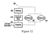
- FIG. 12 an alternative refrigerating fluid circuit is shown and is generally designated 600.
- the refrigerating fluid circuit 600 includes a first compressor 602 and a second compressor 604 that are connected in parallel to each other and connected in series to a condenser 606 and an evaporator 608.
- An expansion valve 610 is also connected between the condenser 606 and the evaporator 608 to complete the fluid circuit.
- glycol is pumped to and from the evaporator 608 from a glycol bath.
- the compressors 602, 604 are variable speed direct current (dc) compressors that can be controlled by a controller, e.g., a computer or any other microprocessor.
- dc direct current
- the controller preferably includes an algorithm that can prevent either compressor from being energized when the other compressor is fully loaded. It can be appreciated that the two compressors 602, 604 working in parallel with each other increase the cooling power of the refrigerating fluid circuit 600.
- FIGS 13 and 14 show an exemplary, non-limiting saline pump assembly, generally designated 650.
- the pump assembly 650 includes a diaphragm pump 652 that is removably engaged with a pump support platform 654.
- the pump 652 is similar to the high efficiency diaphragm pump disclosed in U.S. Patent Numbers 5,791,882 and 5,800,136 , incorporated herein by reference.
- Figure 13 shows that the pump support platform 654 includes an upper plate 656 and a lower plate 658 that, in a preferred embodiment, are attached to each other, e.g., by threaded fasteners. As shown in Figure 13 , plural feet 660 extend from the lower plate 658 and provide stable support for the pump support platform 654. Figure 13 also shows that a pump drive assembly 662 is incorporated into the lower plate 658 of the pump support platform 654.
- the pump drive assembly 662 includes a motor and a drive shaft, described below, that extends through the upper plate 656 of the pump support platform 654 and engages the pump 650.
- the pump support platform 654 includes a quick-release locking arm 664 that prevents the pump 652 from being disengaged with the pump support platform 654 - unless the locking arm 664 is rotated to release the pump 652.
- Figures 14 and 15 also show that the pump support platform 654 includes an overflow bore 665 through which any saline that may leak from the pump 652 can flow.
- Figure 14 further shows that the pump 652 includes an inlet 666 and an outlet 668.
- the pump 652 i.e., the outlet 668 thereof, can be connected to the air trap vessel 418 ( Figure 11 ) that is downstream from the pump 652.
- FIG. 15 shows that the upper plate 656 of the pump support platform 654 is formed with a generally cylindrical pump locking bore 672.
- the outer periphery of the pump locking bore 672 is radially formed with a first slot 674, a second slot 676, and a third slot 678.
- each slot 674, 676, 678 is equally spaced around the outer periphery of the pump locking bore 672.
- each slot 674, 676, 678 is curved to match the radius of curvature of the pump locking bore 672 and each slot 674, 676, 678 terminates in a semi-cylindrical bay 680, 682, 684.
- FIG 15 also shows that a drive shaft 686 extends from the pump drive assembly 662 ( Figure 13 ) through the upper plate 656. It is to be understood that the pump drive assembly 662 includes a motor 687 for rotating the drive shaft 686. The motor 687 can be directly connected to the drive shaft 686, as shown, or it can be geared thereto.
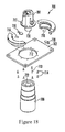
- Figure 16 shows further details concerning the construction of the pump 652.
- the pump 652 includes a generally cylindrical lower housing 688.
- a first generally cylindrical leg 690, a second generally cylindrical leg 692, and a third generally cylindrical leg 694 are equally spaced around the periphery of the lower housing 688.
- Figure 16 shows that the pump 652 further includes a drive shaft receptacle 696 into which the drive shaft 686 ( Figure 15 ) extends when the pump 652 is removably engaged with the pump support platform 654. It is to be understood that the drive shaft 686 is keyed to the drive shaft receptacle 696.
- the pump 652 can be engaged with the pump support platform 654 by aligning the cylindrical legs 690, 692, 694 with the semi-cylindrical bays 680, 682, 684 established by the pump locking bore 672.
- the drive shaft 686 is also aligned with the drive shaft receptacle 696.
- the pump 652 can be slid toward the pump support platform 654 until the lower housing 688 of the pump 652 contacts the upper plate 656 of the pump support platform 654.
- the pump 652 is then rotated within the pump locking bore 672 until each leg 690, 692, 694 of the pump 652 reaches a respective end of each slot 674, 676, 678 formed by the pump locking bore 672.
- one leg 690, 692, 694 of the pump 652 rides against and then past the quick-release locking arm 664 until the quick-release locking arm 664 clears the leg 690, 692, 694 and snaps under spring bias to a position to prevent the pump 652 from being removed from the pump support platform 654.
- a pump 652 can be easily engaged and disengaged with the pump support platform 654 during use.
- a first sterilized pump can be used in conjunction with the treatment of a first patient.
- the now-used pump can be removed and replaced with a second sterilized pump to be used in conjunction with the treatment of a second patient.
- the pump support platform 654 (and the motor therein) need not be replaced for each new pump and the costs of utilizing the heat/cooling system of the present invention are reduced.
- a saline pump assembly 700 includes a pump support platform 702 and a positive displacement gear pump 704.
- the gear pump 704 can incorporate some or all of the features set forth in U.S. Patent Numbers 6,270,324 ; 6,210,138 ; 6,158,994 ; 5,494,416 ; 5,219,274 ; 5,165,868 ; and 4,065,235 , all of which are incorporated herein by reference.
- the pump support platform 702 includes a pump drive motor 706 that is preferably a brushless, direct current motor.
- Figures 17 and 18 show that the pump support platform 702 includes a first support collar 708 and a second support collar 710 that fit into a generally cylindrical pump locking bore 712 formed in the support platform 702.
- Plural fasteners 714 can be used to affix the support collars 708, 710 to the support platform 702.
- the gear pump 704 fits into the support collars after they are inserted in the bore 712.
- a first spring loaded ball plunger 715 and a second spring loaded ball plunger 716 are provided and can be used to removably engage the gear pump 704 with the support platform 702.
- One or more alignment pins 713 can be used to properly align the gear pump 704 when it is engaged with the support platform 702.
- the ball plungers 715, 716 engage a metal flange 717 around the gear pump 704 and provide a downward force on the metal flange 717 in order to keep the gear pump 704 installed in the support platform 702.
- each optical sensor 718, 719 includes an emitter (not shown) and a detector (not shown) that are configured to transmit an optical signal toward the space in which the gear pump 704 occupies when it is properly installed and detect reflection from the gear pump 704 when it is, indeed, properly installed.
- Figure 18 further shows that the gear pump 704 includes a cylindrical magnet 720 that extends from the gear pump 704. It is to be understood that the cylindrical magnet 720 is attached to a drive shaft (not shown) within the gear pump 704 and as the cylindrical magnet 720 rotates it rotates the drive shaft. Further, the motor 706 includes a cup-shaped magnet 722 that is sized and shaped to receive the cylindrical magnet 720 and magnetically engage the cylindrical magnet 720. The cup-shaped magnet 722 is coupled to a drive shaft (not shown) within the motor 706 and the motor 706 can be energized to rotate the cup-shaped magnet 722.
- the gear pump 704 can be removably engaged with the support platform 702.
- the cylindrical magnet 720 is magnetically coupled to the cup-shaped magnet 722. Accordingly, as the cup-shaped magnet 722 is rotated by the motor 706 it causes the cylindrical magnet 720 to rotate and which, in turn, causes the gear pump 704 to pump fluid therethrough.
- the gear pump 704 includes a bypass relief valve (not shown) that opens on high pressure.
- a bypass relief valve the magnets 720, 722 can be magnetized such that the magnetic coupling established therebetween can be broken under conditions of overpressure.
- the speed of the pump 704 can be established for the desired heat exchange rate.
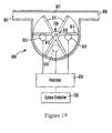
- the flow detector 800 includes a preferably clear, plastic housing 802 having an inlet 804 and an outlet 806.
- a lightweight, preferably plastic paddle wheel 808 is installed within the housing 802 on an axle 810.
- the paddle wheel 808 includes a central hub 812 from which preferably three opaque, plastic paddles 814 extend radially (it is to be understood that each paddle 814 includes a pair of opposing paddle blades).
- the paddles 814 are positioned around the hub 812 approximately one-hundred and twenty degrees (120°) from each other. It can be appreciated that fluid flowing from the inlet 804 to the outlet 806 flows tangential to the paddle wheel 808 and causes it to spin.
- three opaque walls 815 are formed around the paddle wheel 808 between alternating pairs of adjacent paddle blades.
- IR T/R LED infrared transmitter/receiver light emitting diode
- the IR T/R LED pairs 816 are positioned on an imaginary circle concentric with the axle 810.
- the IR T/R LED pairs are arranged so that a center pair 816 is aligned with the axle 810 and two side pairs 816 flank the center pair 816.
- Each side pair is approximately plus-or-minus sixty-four degrees ( ⁇ 64°) from the center pair 816 on the imaginary circle. This arrangement insures that regardless of the position of the pin wheel 808, one of the three signal paths established by the IR T/R LED pairs 816 through the housing 802 is always unblocked by the paddle wheel 808.
- FIG. 19 further shows that each IR T/R LED pair 816 is connected to a processor 818 that, in turn, is connected to a system controller 820.
- the processor 818 includes a program that, based on the signals received from the IR T/R LED pairs 816, allows the processor 818 to determine if the paddle wheel 808 is rotating and fluid is flowing through the housing and accordingly, the working fluid circuit. If not, an alarm can be activated.
- Figure 20 shows the saline flow detection logic that commences at block 850 wherein the flow detector 800 is energized, i.e., its power is turned on.
- decision diamond 852 it is determined whether pulses are being received at the processor 818.
- the pulses represent motion of the paddle wheel 808, i.e., the motion of the paddles through the light beams established by the IR T/R LED pairs 816. If there are indeed pulses, the logic moves to decision diamond 854 where it is determined whether a timer has expired. If the timer has not expired, the logic loops back to decision diamond 852 and continues as described above. If so, the logic moves to block 856 and an "optics error" message is presented to the user. The logic then ends at state 858.
- the logic moves to decision diamond 860 where it is determined whether all three IR T/R LED pairs 816 are on. If so, the logic moves to decision diamond 862 where it is determined if all three IR T/R LED pairs 816 are operating properly. This can be determined, e.g., by sequentially toggling the IR T/R LED pairs 816 on and off. If it is determined that the IR T/R LED pairs 816 are not operating properly, the logic moves to block 856 where an "optics error" message is presented to the user. The logic then ends at state 858. Otherwise, an "optics ok, no pinwheel” message is presented to the user. The logic then ends at state 858.
- decision diamond 860 if all three IR T/R LED pairs 816 are not on, the logic moves to decision diamond 866 where it is determined if two out of three of the IR T/R LED pairs 816 are on. If so, the logic moves to decision diamond 868 where it is determined whether the two IR T/R LED pairs 816 are operating properly, e.g., by toggling the two IR T/R LED pairs 816 on and off. If the two IR T/R LED pairs 816 are not operating properly, the logic moves to block 856 where an "optics error" message is presented to the user. The logic then ends at state 858.
- the logic moves to decision diamond 870 where it is determined if signal pulses are present. If not, the logic moves to block 872 where a "no flow" message is presented to the user. The logic then loops back to decision diamond 870.
- decision diamond 870 if pulses are present, the logic moves to decision diamond 874 where it is determined if all three IR T/R LED pairs 816 are operating properly. If so, an "optics ok, flow” message is indicated to the user at block 876. Otherwise, an "optics warning, flow” message is indicated to the user at block 878. From block 876 or block 878, the logic moves to block 880 where it is determined if pulses are present. If pulses are indeed present, the logic returns to decision diamond 874 and continues as described above. Conversely, if pulses are not present, the logic proceeds to block 882 where a "no flow" message is presented to the user. The logic then ends at state 858.
- decision diamond 884 it is determined if one IR T/R LED pair 816 is on. If not, the logic proceeds to block 856 where an "optics error" is presented to the user. The logic then ends at state 858. If the IR T/R LED pair 816 is on, the logic moves to decision diamond 886 where it is determined whether the IR T/R LED pair 816 is operational. If the IR T/R LED pair 816 is not operational, the logic continues to block 856 where an "optics error" is presented to the user. The logic then ends at state 858. If the IR T/R LED pair 816 is operating properly, the logic moves to decision diamond 870 and continues as described above.
- the flow detector 800 can indicate flow through the working fluid circuit only if signal pulses are output by the flow detector 800. Moreover, while the paddle wheel 808 is rotating, the processor 818 is constantly testing each of the IR T/R LED pairs 816 by sequentially toggling each of the IR T/R LED pairs 816 on and off and reading the signals output thereby.
- the glycol flow detection logic commences at block 900 with a do loop wherein periodically, the following steps are performed.
- the heater 166 ( Figure 4 ) is periodically pulsed.
- decision diamond 904 it is determined if there is a sudden increase in temperature (e.g., above a predetermined quantity), as indicated by the thermocouple temperature sensor 170 ( Figure 4 ). If not, the logic ends at state 906. Otherwise, the logic proceeds to block 908 where it is indicated to a controller that there is a problem with the glycol circulation. It can be appreciated that in response to the indication of a problem, the controller can shut off power to the heater at block 910.
- the power required to cool the patient can be viewed at the display device 98. It is to be understood that the power equation described below is most accurate for a patient having a weight of approximately seventy-five kilograms (75 kg). Accordingly, the power used to cool a patient can be determined using the following equation: d ⁇ T pt / dt °C / min ⁇ 60 ⁇ min / hr 1 , 4 ⁇ °C / hr ⁇ 100 ⁇ w ⁇ - 1 where: dT pt /dt is determined by the equation disclosed above.
- a heat exchange system for an indwelling heat exchange catheter comprising:
- the compressor may be a variable speed direct current (DC) compressor.
- DC direct current
Abstract
Description
- The present invention relates generally to methods and apparatus for exchanging heat with the body of a patient.
- It has been discovered that the medical outcome for a patient suffering from severe brain trauma or from ischemia caused by stroke or heart attack is improved if the patient is cooled below normal body temperature (37°C). Furthermore, it is also accepted that for such patients, it is important to prevent hyperthermia (fever) even if it is decided not to induce hypothermia. Moreover, in certain applications such as post-CABG surgery, it might be desirable to rewarm a hypothermic patient.
- As recognized by the present invention, the above-mentioned advantages in regulating temperature can be realized by cooling or heating the patient's entire body. Moreover, the present invention understands that since many patients already are intubated with central venous catheters for other clinically approved purposes anyway such as drug delivery and blood monitoring, providing a central venous catheter that can also cool or heat the blood requires no additional surgical procedures for those patients. However, single purpose heat exchange catheters such as are made by Innercool Therapies of San Diego, CA and Radiant Medical of Portola Valley, CA can also be less optimally used.
- Regardless of the particular catheter used, it is clear that heat must be removed from or added to the coolant that flows through the catheter. As recognized herein, it is desirable that a heat exchange system for a heat exchange catheter consume minimal energy and space. Small size is desired because space is often at a premium in critical care units. Moreover, as also recognized herein, for patient comfort it is desirable that such a heat exchange system generate a minimum amount of noise. As still further understood by the present invention, it is desirable that the heat exchange system be easy to use by health care personnel, and provide for monitoring systems and convenient temperature control.
U.S. Patent Number 6,146,411 , incorporated herein by reference, discloses one such heat exchange system. It is the object of the present invention to still further address one or more of the above-noted considerations. - A heat exchange system for an indwelling heat exchange catheter includes a heat exchange bath that is configured to receive a conduit that carries working fluid to and from the catheter. A heating/coolant fluid is disposed within the bath to exchange heat with the working fluid. The heating/coolant fluid flows through a heat exchanger that includes a refrigerant and two or more compressors that are connected in parallel to each other. Moreover, a heating/coolant fluid pump circulates the heating/coolant fluid between the heat exchanger and the heat exchange bath.
- In a preferred embodiment, the compressors are variable speed direct current (DC) compressors. Also, a positive displacement gear pump preferably pumps the working fluid, e.g., saline, to and from the catheter. In a preferred embodiment, the pump is removably engaged with a motor.
- In another aspect of the present invention, a heat exchange system for an indwelling heat exchange catheter includes a heat exchange bath that is configured to receive a conduit that carries working fluid to and from the catheter. A pump communicates with the conduit and pumps the working fluid to and from the catheter.
- In yet another aspect of the present invention, a fluid pump assembly includes a pump support platform. A pump is removably engaged with the pump support platform. In this aspect, the pump pumps working fluid to and from an intravascular catheter.
- In still another aspect of the present invention, a heat exchange system for an indwelling heat exchange catheter includes a heat exchange bath that is configured to receive a conduit that carries working fluid to and from the catheter. In this aspect of the present invention, a flow detector communicates with the conduit and detects when working fluid is flowing through the conduit.
- In yet still another aspect of the present invention, a fluid flow detector includes
a clear housing and a paddle wheel that is rotatably disposed within the housing. The fluid flow detector further includes three infrared transmitter/receiver light emitting diode pairs. Each infrared transmitter/receiver light emitting diode pair establishes a signal path through the housing. - The details of the present invention, both as to its construction and operation, can best be understood in reference to the accompanying drawings, in which like numerals refer to like parts, and which:
-
-
Figure 1 is a schematic diagram of a heating/cooling system in accordance with the present invention; -
Figure 2 is a cross-sectional view of a heat exchange bath with the water glycol return line and level detector omitted for clarity; -
Figure 3 is a cross-sectional view of a fluid level detector; -
Figure 4 is a detailed cross-sectional view of a chiller/heater; -
Figure 5 is a flow chart of the overall operation logic of the present invention; -
Figure 6 is a flow chart of the linear mode operation logic of the present invention; -
Figure 7 is a flow chart of a first portion of the compressor control logic; -
Figure 8 is a flow chart of a second portion of the compressor control logic; -
Figure 9 is a flow chart of a third portion of the compressor control logic; -
Figure 10 is an exemplary graph of patient temperature and bath temperature versus time; -
Figure 11 is a schematic diagram of an alternative heating/cooling system; -
Figure 12 is a schematic diagram of an alternative refrigerating fluid circuit; -
Figure 13 is a side plan view of a saline pump assembly; -
Figure 14 is a top plan view of the saline pump assembly; -
Figure 15 is a top plan view of a pump support platform; -
Figure 16 is a bottom plan view of a pump; -
Figure 17 is a perspective view of an alternative saline pump assembly; -
Figure 18 is an exploded view of the alternative saline pump assembly; -
Figure 19 is a side plan view of a preferred flow detector; -
Figure 20 is flow chart of the saline flow detection logic; and -
Figure 21 is flow chart of the glycol flow detection logic. - Referring initially to
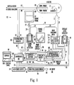
Figure 1 , a patient heating/cooling system is shown and generally designated 10. As shown, thesystem 10 includes three separate fluid circuits: a saline circuit (also referred to as the working fluid circuit), a water glycol circuit (also referred to as' the heating/cooling fluid circuit), and a refrigerant circuit (also referred to as the refrigerating fluid circuit.) - Taking the saline circuit first, an indwelling
heat exchange catheter 12 that can be inserted into apatient 13 during an operation is connected to aheat exchange bath 14 by asaline supply line 16. Thesupply line 16 is connected to a coiled or helicalheat exchange tube 17 that is immersed in thebath 14 fluid to exchange heat therewith. In turn, theheat exchange tube 17 is connected to a peristaltictubing saline pump 18 byfluid line 20. Preferably, thesaline pump 18 draws saline from asaline reservoir 22 viafluid line 24. As shown, thesaline reservoir 22 is disposed within asaline level detector 25 that, as described in detail below, helps control thesaline pump 18 based on the level of saline in thelevel reservoir 22. It is to be understood that in a preferred embodiment, thesaline pump 18 has four modes: a standby or off mode, two treatment modes (i.e., two treatment speeds), and an idle mode wherein thesaline pump 18 operates very slowly, but does not stop. In the idle mode, thepatient 13 is effectively thermally decoupled from the heating/cooling system 10. - As further shown in
Figure 1 , asaline source 26 provides saline to thesaline reservoir 22 viafluid line 28. In a preferred embodiment, thesaline source 26 is an intravenous (IV) bag and aline clamp 27 is installed onfluid line 28 between thesaline source 26 and thesaline reservoir 22. It is to be understood that after thesaline reservoir 22 is filled theline clamp 27 is clamped onfluid line 28 to isolate thesaline source 26 from thesaline reservoir 22.Figure 1 shows asaline return line 29 communicates saline from thecatheter 12 to thesaline reservoir 22 to complete the saline circuit. It is to be appreciated that thetubes -
Figure 1 also shows asystem controller 30 that is connected to thesaline level detector 25 viaelectrical line 32 andelectrical line 34, i.e., one for each infrared detector that is associated with thesaline level detector 25 as described below. Preferably, thesystem controller 30 is also connected to asafety switch 36 of thesaline pump 18 viaelectrical line 38. As described in further detail below, thesystem controller 30 receives signals from thesaline level detector 25 regarding the level of saline therein and uses this information to control thesaline pump 18, including opening thesafety switch 36 to de-energize thesaline pump 18 under certain low saline level conditions. - It is to be understood that within the saline circuit, saline is circulated to and from the
catheter 12 through the helicalheat exchange tube 17 in theheat exchange bath 14. As described in detail below, theheat exchange bath 14 is filled with heating/cooling fluid, preferably water glycol. The water glycol can be heated or cooled in order to heat or cool the saline and thus, increase or decrease the temperature of the patient 13 into which thecatheter 12 is inserted. Also, it is to be understood that the preferred working fluid is saline, but any similar fluid well known in the art can be used. - Now considering the water glycol circuit, the water glycol circuit communicates with a chiller/
heater 40 via a waterglycol supply line 42 and a waterglycol return line 44. Awater glycol pump 46 is installed in the waterglycol return line 44 to circulate water glycol through the water glycol circuit.Figure 1 shows that theheat exchange bath 14 is also in fluid communication with awater glycol reservoir 47 installed within a waterglycol level detector 48 viafluid line 50. In accordance with principles described below, the waterglycol level detector 48 is used to determine the level of water glycol within theheat exchange bath 14. - Further, the
system controller 30 is connected to the chiller/heater 40 viaelectrical lines system controller 30 is connected to asafety switch 55 at thewater glycol pump 46 viaelectrical line 56 and to thecoolant level detector 48 viaelectrical line 58 andelectrical line 60. Thus, thesystem controller 30 can control the operation of the chiller/heater 40 based on signals from a temperature monitor, described below, and control the operation of thewater glycol pump 46 based on level signals from infrared detectors, also described below, that are disposed within the waterglycol level detector 48. As shown, thesystem controller 300 is also connected to atemperature sensor 57 placed at the outlet of the chiller/heater viaelectrical line 59. Thecontroller 30 uses input from thetemperature sensor 57 to control the chiller/heater 40 andother system 10 components. - It is to be understood that as the water glycol is pumped through the water/glycol circuit the chiller/
heater 40 can heat or cool the water glycol. Within theheat exchange bath 14, the water glycol exchanges heat with the saline. Thus, the water glycol can be used to heat or cool saline and in turn, heat or cool the patient in which thecatheter 12 is intubated. It is to be further understood that water glycol is the preferred heating/cooling fluid. However, any other fluid with similar properties can be used. - Now considering the third (refrigerant) circuit, a variable speed direct current (DC)
compressor 62 is in fluid communication with the chiller/heater 40 via arefrigerant supply line 64 and arefrigerant return line 66. It is to be understood that thecompressor 62 is filled with refrigerant, e.g., R134a. Acompressor controller 68 is connected to thecompressor 62 via anelectrical line 70. In turn, thesystem controller 30 is connected to thecompressor controller 68 viaelectrical line 72. Thecompressor controller 68 is also connected to a heater, described below, within the chiller/heater 40 viaelectrical line 73. - It is to be understood that the
system controller 30 receives temperature signals from the temperature monitor, described below, and uses these signals to control the operation of thecompressor 62 and the heater. Thecompressor 62 is used to cool the water glycol that is pumped through the chiller/heater 40 by thewater glycol pump 46. - Continuing to refer to
Figure 1 , aDC power supply 74 is connected to thesystem controller 30 by anelectrical line 76. In turn, theDC power supply 74 preferably is connected to' an isolation transformer (XFMR) 78 byelectrical line 80. TheXFMR 78 can be connected to an alternating current (AC)input 82, e.g., a standard one hundred and twenty volt (120V) wall outlet, via apower cord 84. Thesystem 10 can also be configured to work accommodate one hundred to two hundred and forty volts AC (100 - 240 VAC). - As further shown in
Figure 1 , atemperature monitor 86 is connected to thesystem controller 30 via anelectrical line 88. A firstpatient temperature probe 90 and a secondpatient temperature probe 92 preferably are connected to the temperature monitor 86 viaelectrical lines patient 13. Moreover, the temperature monitor 86 sends signals to thesystem controller 30 representing the temperature of thepatient 13. These signals are used by thesystem controller 30 to control the operation of the chiller/heater 40, thesaline pump 18, and theDC compressor 62. -
Figure 1 shows adisplay device 98 that is connected to thesystem controller 30 viaelectrical line 100 andelectrical line 102. Preferably, thedisplay device 98 provides a visual indication of the patient's temperature and the bath temperature. For example, thedisplay device 98 can be used to output graphs of minute by minute patient temperature (for, e.g., twenty one days) and water glycol bath temperature thedisplay device 98 can also be used to provide information regarding the cooling power required by the patient, whether the system is heating or cooling the bath, and at which rate, e.g., low, medium, or maximum, the system is heating or cooling the bath. Further, thedisplay device 98 can display the current patient temperature and the patient target temperature. - It is to be understood that a user can scroll the graphs left or right with respect to a stationary cursor within the center of the display. As the graphs are scrolled, information corresponding thereto can be displayed. As shown, the
display device 98 also includes acontrol panel 104 to allow a user, i.e., a doctor or a nurse, to input data, such as a target patient temperature, to thesystem 10. - Referring now to
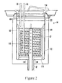
Figure 2 , details of one preferred, non-limitingheat exchange bath 14 are shown.Figure 2 shows that the preferredheat exchange bath 14 includes a bottom 110 having a generally cylindricalcontinuous sidewall 112 extending therefrom. As shown, thebottom 110 of thebath 14 is formed with ahole 114 and the waterglycol supply line 42 is connected thereto. A preferablyvertical standpipe 116 extends from the end of the waterglycol supply line 42 into the interior of thebath 14. In a preferred embodiment, thestandpipe 116 is perforated along its length with a series of four hole rings 118 out of which water glycol flows into thebath 14. These four hole rings 118 ensure radial movement of the water glycol through theheat exchange tubing 17, i.e., between and across the turns of the coil. It can be appreciated that in lieu of thestandpipe 116, a small impeller (not shown) can be mounted on thebottom 110 of thebath 14 to circulate the water glycol therein. - As shown in
Figure 2 , the generally spiral-shapedheat exchange tubing 17 is disposed within thebath 14 such that when thebath 14 is filled with water glycol theheat exchange tubing 17 is fully immersed in the water glycol.Figure 2 shows that thesaline supply line 16 is connected to one end of theheat exchange tubing 17. Conversely, thefluid line 20 from thesaline pump 18 is connected to the other end of theheat exchange tubing 17. As shown, to center and support the spiral-shaped tubing set 120 around thestandpipe 116, four vertical stanchions 122 (only two shown inFigure 2 ) extend up from thebottom 110 of thebath 14 and touch the outer surface of the tubing set 120. In the alternative, theheat exchange tubing 17 can rest against thesidewall 112 of thebath 14. -
Figure 2 further shows that thebath 14 is covered by alid 124. Preferably, the bottom of thelid 124 is spaced above the top of the water glycol within thebath 14 in order to establish adead air space 126 between thelid 124 and the water glycol. Thisdead air space 126 acts as an insulator to minimize parasitic heat loads, control the evaporation of the water glycol, and prevent progressive overfilling of thebath 14 by condensation from the ambient air. Also, thelid 124 can be sealed against thewall 112 by a resilient, preferably silicone,gasket 128. - Referring now to
Figure 3 , details of the preferred embodiment of thesaline level detector 25 are shown. It is to be understood that the waterglycol level detector 48 operates using the same principles as thesaline level detector 25. As shown inFigure 3 , thesaline level detector 25 includes ahousing 130 that is preferably made from acetal, e.g., Delrin® manufactured by E.I. Dupont De Nemours & Co. of Delaware. Thehousing 130 is formed with a preferably "U" shapedcentral bore 132 in which the preferablyclear saline reservoir 22 is disposed.Figure 3 shows that the housing is formed with a firsttransverse bore 134, a secondtransverse bore 136, and a thirdtransverse bore 138 leading to thecentral bore 132. - As shown, the
saline level detector 25 includes a light emitter, e.g., an infrared light emitting diode (IR LED) 140, that is mounted in thefirst bore 134 on one side of thelevel detector 22. On the other hand, preferably two light detectors, such as afirst IR detector 142 and asecond IR detector 144, are placed on the opposite side of thesaline level detector 25 from the LED 140 within the second and thirdtransverse bores detectors - In the presently preferred embodiment, IR LED 140 and the
IR detectors first IR detector 142 if the saline level is below a predetermined level, e.g., the level of the IR LED 140 and theIR detectors first IR detector 142 as indicated by the dashedline 146. Conversely, if the saline is at the proper level within thesaline level detector 25, the IR light beam is refracted so that it is detected by thesecond IR detector 144. In this case, the IR light beam takes the path indicated byline 148. - It is to be understood that the IR light beam can be modulated, i.e. pulsed, e.g., at nine and a half kiloHertz (9.5 kHz), to avoid false detections caused, e.g., by other light sources placed in the same room as the
level detector 25 and/or bubbles in thesaline reservoir 22. For this purpose, thefirst IR detector 142 andsecond IR detector 144 can be connected to upper andlower tone detectors controller 30 can activate an alarm at thedisplay device 98. The alarm can include a visible alarm, e.g., a light, or an audible alarm, e.g., a buzzer. Moreover, when the saline level drops below the predetermined level thecontroller 30 can de-energize thesaline pump 18 by opening thesafety switch 36. -
Figure 4 shows the details regarding one preferred, non-limiting implementation of the chiller/heater 40. As shown inFigure 4 , the chiller/heater 40 is a shell-and-tube heat exchanger having alower chamber 160, anupper chamber 162, andplural tubes 164 communicating water glycol therebetween. It is to be understood that water glycol flows into thelower chamber 160, up thetubes 164, into to theupper chamber 162, and out of theupper chamber 162 to theheat exchange bath 14. Refrigerant, e.g., R134a, flows around thetubes 164 to cool the water glycol therein. Aresistive heater element 166 is disposed in thelower chamber 160 and extends partially up anenlarged center tube 168 for heating the water glycol in the chiller/heater 60. As shown, theheater element 166 can include a built-inthermocouple temperature sensor 170 that can be used as described in detail below to determine if glycol is flowing through the chiller/heater 60. It is to be appreciated that in a less preferred embodiment the chiller/heater 40 and theheat exchange bath 14 can be combined into a single unit. Moreover, it is to be appreciated that thetemperature sensor 170 can be connected to the system controller. - Referring now to
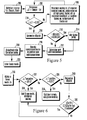
Figure 5 , the overall operation logic of the present invention is shown and commences atblock 200 wherein thecontroller 30 is initialized and the patient temperature (Tpt), the patient target temperature (Ttarget), and the bath temperature (Tbath,) are received. Preferably, Tpt is received from thetemperature monitor 86, specifically from thesecond temperature probe 92. Moving to block 202, a temperature differential, ΔT, is determined by subtracting Tpt from Ttarget Next, atdecision diamond 204 it is determined whether the absolute value of ΔT is less than a predetermined amount, e.g., one tenth of a degree Celsius (0.1 °C). - If the absolute value of ΔT is greater than 0.1 °C, the logic moves to block 206 where the
system 10 enters maximum cooling mode or maximum warming mode. It is to be understood that if ΔT is negative thesaline pump 18 is brought to full speed, thecompressor 62 is turned on at high speed, and theheater 166 is turned off to cool the patient. Conversely, if ΔT is positive, thesaline pump 18 is brought to full speed, thecompressor 62 is turned off, and theheater 166 is turned on to warm the patient. - Returning to
decision diamond 204, if the absolute value of ΔT is less than 0.1 °C, the logic moves to block 208 where the rate of change of Tpt with respect to time, dTpt/dt, is determined using the following equation:
where,
n = 10 unless there has not yet been 10 minutes worth of patient temperature data
Tpt = Patient temperature - From
block 208, the logic moves todecision diamond 210 where it is determined whether the absolute value of dTpt /dt is greater than thirty six hundredths of a degree Celsius per hour (0.36 °C/hr). If not, the logic continues to block 212 and a new Tbath is determined. The new Tbath is determined based on the rate of change of patient temperature. A higher rate of change results in a new Tbath that is further away from the current Tbath and a lower rate of change results in a new Tbath that is closer to the current Tbath If dTpt/dt is indeed greater than 0.36 °C/hr and negative, meaning that thepatient 13 is being rapidly cooled and does not require saline circulation through the catheter, the logic moves to block 214 where thesaline pump 18 is idled. Thereafter, the logic moves to 212 and a new Tbath is determined. - After
block 212, the logic proceeds to block 216, wherein thecompressor 62 and chiller/heater 40 are operated in accordance with the rules set forth below to achieve the new Tbath Continuing to block 218, in a preferred embodiment, thesaline pump 18 is selectively idled per the following rules: - 1. Condition: A warming treatment has just started and the water glycol temperature is lower than Tpt
Rule: Thesaline pump 18 idled until the water glycol temperature is at least as warm as Tpt - 2. Condition: A controlled heating/cooling rate treatment has just started and the water glycol temperature is not within one degree Celsius (1 °C) of the water glycol reference temperature, Tref' (Tpt - 6 °C when cooling, Tpt + 1 °C when heating).
Rule: Thesaline pump 18 is idled until the water glycol temperature is within 1 °C of Tref - 3. Condition: Tpt is within 0.1 °C of Ttarget and
dTpt/dt < 0.36 °C/hr.
Rule: Thesaline pump 18 is idled at a very low rate until the water glycol temperature reaches Tref. - 4. Condition: PID has been controlling the system,
the error exceeds the overshoot threshold, and the water glycol temperature is warmer than Tpt.
Rule: Thesaline pump 18 is idled until the water glycol temperature is lower than Tpt. - 5. Condition: PID has been controlling the system, the error exceeds the undershoot threshold, and the water glycol temperature is cooler than Tpt.
Rule: Thesaline pump 18 is idled until the water glycol temperature is higher than Tpt. - After the
saline pump 18 is selectively idled as described above, the logic proceeds to block 220 where the system enters the linear cooling mode, described below. -
Figure 6 shows the linear mode operation logic of the present invention. Commencing at block 230 a do loop is entered wherein while in the linear mode, the succeeding steps are performed. In the linear mode, several "fail safe" tests are monitored for to revert to maximum cooling or heating in the event that a rapid patient temperature change occurs. For instance, atdecision diamond 232, if it is determined that ΔT is greater than one half a degree Celsius (0.5 °C) and has a negative sign, the system exits linear mode and enters maximum cooling mode atblock 234. Also, if atdecision diamond 236 it is determined that ΔT is positive and greater than three tenths of a degree Celsius (0.3 °C), the logic moves to block 238 where the linear mode is exited and the maximum warming mode is entered. Moreover, atblock 240, dTpt/dt is determined using the equation described above. - Proceeding to
decision diamond 242, it is determined whether dTpt/dt is greater than seven tenths of a degree Celsius per hour (0.7 °C/hr) for the last ten (10) minutes. If so, the logic moves to block 234 where the linear mode is exited and the maximum cooling mode is entered. If dTpt/dt is less than 0.7 °C/hr for the last 10 minutes, the logic returns todecision diamond 232 and continues as described above. - Referring now to
Figure 7 , the control logic of the compressor is shown and commences atblock 250 with a do loop, wherein after a new Tbath is determined, the following steps are performed. Atdecision diamond 252, it is determined whether the new Tbath is greater than the current Tbath. If the new Tbath is lower than the current Tbath, the logic moves to block 254 and theheater 166 is deactivated while thecompressor 62 is activated at maximum speed to cool the water glycol. - Continuing to
decision diamond 256, it is determined whether the current bath temperature is within a predetermined range, e.g., two-tenths degrees Celsius (0.2 °C) of the new Tbath. If not, the logic moves to block 258 where the cooling of the water glycol is continued. The logic then returns todecision diamond 256. If the current bath temperature is within the predetermined range of the new Tbath, the logic moves to block 260 wherein the compressor speed is progressively reduced. - From
block 260, the logic moves todecision diamond 262 where it is determined whether the current temperature is stable at the new Tbath. If so, the logic moves to block 264 and thecompressor 62 is held at the current speed to maintain the temperature at the new Tbath. If, atdecision diamond 262, the temperature has not stabilized at the new Tbath, the logic moves todecision diamond 266 where it is determined whether the minimum compressor speed has been reached. If the minimum compressor speed has not been reached, the logic returns to block 260 and continues as described above. Conversely, if the minimum compressor speed has been reached, the logic moves to block 268 where the heater power is progressively increased. - Next, the logic continues to
decision diamond 270 where it is determined if the current temperature has stabilized at the new Tbath. If not, the logic returns to block 268 where the heater power continues to be progressively increased. If, on the other hand, the current temperature has stabilized at Tbath the logic moves to block 272 where the current power is maintained. Thereafter, the logic moves to block 264 where the compressor is idled at the current speed, in this case the lowest speed, in order to maintain the temperature at Tbath. In a preferred, non-limiting embodiment, the lowest temperature to which the bath can be commanded is one-half degree Celsius (0.5 °C). - Returning to
decision diamond 252, if the new Tbath is greater than the current temperature, the logic proceeds todecision diamond 274 where it is determined whether the new Tbath is less than or equal to a predetermined upper bath limit, e.g., forty two degrees Celsius (42 °C). If the new Tbath is less than the upper bath limit, the logic moves toFigure 8 . However, if the new Tbath is equal to the upper bath limit, the logic moves toFigure 9 . - Proceeding to
Figure 8 , if the new Tbath is less than the upper bath limit, the logic proceeds to block 276 where thecompressor 62 is activated at minimum speed and theheater 166 is activated at maximum power. Fromblock 276, the logic moves todecision diamond 278 where it is determined if the current temperature is within a predetermined range, e.g., two-tenths degrees Celsius (0.2 °C) of the new Tbath. If not, the logic proceeds to block 280 and the heating of the water glycol is continued. If the temperature is within the predetermined range, the logic continues to block 282 where the heater power is progressively reduced. - Next, at
decision diamond 284, it is determined whether the current temperature has stabilized at the new Tbath. If the current temperature has stabilized at the new Tbath, the current heater power is maintained to maintain the temperature at the new Tbath. On the other hand, if the current temperature has not stabilized, the logic proceeds todecision diamond 288 where it is determined if the heater duty cycle is equal to zero (0). If not, the logic returns to block 282 where the progressive reduction of the heater power is continued. - If, at
decision diamond 288, the heater duty cycle is equal to zero, indicating that the lowest heating power has been reached, logic continues to block 290 where the speed of thecompressor 62 is progressively increased. Thereafter, atdecision diamond 292, it is determined whether the current temperature has stabilized at the new Tbath. If the temperature has not stabilized, the logic moves to block 290 where the reduction of the compressor speed is continued. On the other hand, if the temperature of the compressor speed has stabilized at Tbath, the logic continues to block 294 where the current compressor speed is maintained. The logic then moves to block 286 and ends. - Returning to decision diamond 274 (
Figure 7 ), if the new Tbath is equal to the upper bath limit, the logic moves toFigure 9 . Atblock 296, the compressor is deactivated and the heater is activated at maximum power. Fromblock 296, the logic moves todecision diamond 298 where it is determined whether the temperature is within a predetermined range, e.g., two-tenths degrees Celsius (0.2 °C), of the new Tbath, If not, the heating of the water glycol is continued atblock 300. If the current temperature is within 3 °C of the new Tbath, the logic proceeds to block 302 where the power of theheater 166 is progressively reduced. Then, atdecision diamond 304, it is determined whether the temperature has stabilized at the new Tbath, If so, the current heater power is maintained to maintain the temperature at the new Tbath. Conversely, if the temperature has not stabilized at the new Tbath, the logic continues todecision diamond 308 where it is determined whether the heater duty cycle has reached zero (0). If the heater duty cycle has not reached zero, the logic returns to block 302 where the progressive reduction of the heater power is continued. On the other hand, if the heater duty cycle has reached zero, thecompressor 62 is briefly cycled in order to cool the water glycol. Next, atdecision diamond 312, it is again determined whether the temperature has stabilized at the new Tbath. If not, the logic returns to block 310 and the compressor is again briefly cycled to cool the water glycol. If, atdecision diamond 312, the temperature has stabilized at the new Tbath, the logic moves to block 306 and ends. - It is to be understood that the system described above has two nested closed-loop controllers: an outer loop and an inner loop. The outer loop is directly responsible for controlling the patient temperature and is driven by the temperature difference between Ttarget and Tpt. On the other hand, the inner loop is directly responsible for the coolant temperature, i.e., Tbath, that is established by the
system controller 30. It is further to be understood that the outer loop logic, i.e., the overall operation logic and linear mode operation logic describe above, resides in thesystem controller 30. The inner loop control logic, i.e., the compressor control logic described above, resides in thecompressor controller 68. As intended by the present invention, when thecompressor controller 68 receives a command to establish a new Tbath, thecompressor controller 68 controls thecompressor 62 and theheater 166, as described above, in order to achieve the new Tbath. - In a preferred, non-limiting embodiment, the
compressor controller 68 has two means of control over thecompressor 62. First, it can turn the power tocompressor 62 on and off via a solid-state DC relay. Second, it can modulate the compressor speed between a maximum value, e.g., thirty five hundred revolutions per minute (3,500 RPM), and a minimum value, e.g., two thousand revolutions per minute (2,000 RPM). - Also, in a non-limiting embodiment, the
compressor controller 68 has only duty-cycle control over theheater 166. Thecompressor controller 68 can modulate the heater power anywhere between zero percent (0 %), i.e., off, and one hundred percent (100 %), i.e., on. Preferably, theheater 166 has a fixed one second (1 s) pulse period. Also, in a preferred embodiment theheater 166 has a maximum power of two hundred and forty watts (240 w). Thus, a fifty percent (50 %) duty cycle corresponds to one hundred and twenty watts (120 w) of time-averaged input power to the water glycol and a twenty five percent (25 %) duty cycle would correspond to sixty watts (60 w) of time-averaged input power. -
Figure 10 shows one exemplary, non-limiting graph of Tpt, represented byline 320, and Tbath, represented byline 322, plotted versus time. As shown, the patient is initially in a hyperthermic state, i.e., the patient has a fever of thirty-nine degrees Celsius (39 °C). The patient is cooled from 39 °C toward a Ttarget equal to thirty-six and one-half degrees Celsius (36.5 °C) preferably over a three hour period at a rate of eight tenths of a degree Celsius per hour (0.80 °C/hr). This can be achieved by entering a maximum cooling mode where the Tbath is one-half a degree Celsius (0.5 °C). - Once Tpt reaches thirty six and six tenth degrees (36.6 °C), the
saline pump 18 preferably is idled to thermally de-couple the patient 13 from thecooling system 10 and the Tbath is increased, e.g., by energizing theheater 166, to approximately twenty-five degrees Celsius (25 °C). By thermally de-coupling the patient 13 from thecooling system 10, Tpt will discontinue the rapid decrease described above while Tbath is increased. - After Tbath reaches 25 °C, the
saline pump 18 is returned to full speed to thermally couple the patient 13 to thecooling system 20. As intended by the present invention, the higher Tbath slows the rate at which thepatient 13 is cooled and helps to maintain Tpt in a state of equilibrium near Ttarget, e.g., within one-tenth of a degree Celsius (0.1 °C) of Ttarget. If necessary, Tbath can be slightly increased or decreased, e.g., less than five degrees Celsius (5 °C), as shown in order to maintain Tpt in the state of equilibrium described above. - Referring now to
Figure 11 , an alternative patient heating/cooling system is shown and generally designated 410. Similar to the above-describedsystem 10, thesystem 410 shown inFigure 11 includes three separate fluid circuits: a saline circuit (also referred to as the working fluid circuit), a water glycol circuit (also referred to as the heating/cooling fluid circuit), and a refrigerant circuit (also referred to as the refrigerating fluid circuit.) - Taking the saline circuit first, an indwelling
heat exchange catheter 412 that can be inserted into apatient 413 during an operation is connected to aheat exchange bath 414 by asaline supply line 416. Thesupply line 416 is connected to a coiled or helicalheat exchange tube 417 that is immersed in the bath fluid to exchange heat therewith. In turn, theheat exchange tube 417 is connected anair trap vessel 418 byfluid line 420. Theair trap vessel 418 is surrounded by anair trap detector 419. As shown, theair trap vessel 418 is connected to asaline pump 422 byfluid line 424. - It is to be understood that the
air trap detector 419 is identical in construction to thesaline level detector 25 described above and shown inFigure 3 and can be used to detect when air is introduced into the working fluid circuit downstream from thepump 422, e.g., by thepump 422 itself. Accordingly, if air is detected in theair trap vessel 418, thepump 422 is immediately shut down by a controller in accordance with the principles discussed earlier. - As further shown in
Figure 11 , asaline source 426 provides saline to thepump 422 viafluid line 427.Figure 11 shows asaline return line 428 that communicates saline from thecatheter 412 to thesaline reservoir 426 to complete the saline circuit. Asaline flow detector 429, described in detail below, is installed along thesaline return line 428 between thecatheter 412 and thesaline reservoir 426.Figure 11 , shows that thesaline flow detector 429 provides feedback to the system controller, described below, viaelectrical line 425. -
Figure 11 also shows asystem controller 430 that is connected to theair trap detector 419 viaelectrical line 432 andelectrical line 434, i.e., one for each infrared detector that is associated with theair trap detector 419. Preferably, thesystem controller 430 is also connected to asafety switch 436 of thesaline pump 422 viaelectrical line 438. As described in further detail below, thesystem controller 430 receives signals from theair trap detector 419 regarding the level of saline therein and uses this information to control thesaline pump 422, including opening thesafety switch 436 to de-energize thesaline pump 422 under certain low saline level conditions. It is to be understood that within the saline circuit, saline is circulated to and from thecatheter 412 through the helicalheat exchange tube 417 in theheat exchange bath 414. - Now considering the water glycol circuit, the water glycol circuit communicates with a chiller/
heater 440 via a water glycol supply line 442 and a water glycol return line 444. Awater glycol pump 446 is installed in the water glycol supply line 442 to circulate water glycol through the water glycol circuit.Figure 11 shows that theheat exchange bath 414 is also,in fluid communication with awater glycol reservoir 447 viafluid line 450. As shown, the water glycol reservoir is installed within a waterglycol level detector 448. In accordance with the principles described above, the waterglycol level detector 448 can be used to determine the level of water glycol within theheat exchange bath 414. - Further, the
system controller 430 is connected to the chiller/heater 440 viaelectrical lines system controller 430 is connected to thecoolant level detector 448 viaelectrical line 458 andelectrical line 460. Thus, thesystem controller 430 can control the operation of the chiller/heater 440 based on signals from a temperature monitor, described below, and control the operation of thewater glycol pump 446 based on level signals from the infrared detectors that are disposed within the waterglycol level detector 448. As shown, thesystem controller 430 is also connected to atemperature sensor 457 placed at the outlet of the chiller/heater viaelectrical line 459. Thecontroller 430 uses input from thetemperature sensor 457 to control the chiller/heater 440 andother system 410 components. - It is to be understood that as the water glycol is pumped through the water/glycol circuit the chiller/
heater 440 can heat or cool the water glycol. Within theheat exchange bath 414, the water glycol exchanges heat with the saline. Thus, the water glycol can be used to heat or cool saline and in turn, heat or cool the patient in which thecatheter 412 is installed. It is to be further understood that water glycol is the preferred heating/cooling fluid. However, any other fluid with similar properties can be used. - Now considering the third (refrigerant) circuit, a variable speed direct current (DC)
compressor 462 is in fluid communication with the chiller/heater 440 via arefrigerant supply line 464 and arefrigerant return line 466. It is to be understood that thecompressor 462 is filled with refrigerant, e.g., R134a. Acompressor controller 468 is connected to thecompressor 462 via anelectrical line 470. In turn, thesystem controller 430 is connected to thecompressor controller 468 viaelectrical line 472. Thecompressor controller 468 is also connected to a heater (Figure 4 ) within the chiller/heater 440 viaelectrical line 473. - It is to be understood that the
system controller 430 receives temperature signals from the temperature monitor, described below, and uses these signals to control the operation of thecompressor 462 and the heater. Thecompressor 462 is used to cool the water glycol that is pumped through the chiller/heater 440 by thewater glycol pump 446. - Continuing to refer to
Figure 11 , aDC power supply 474 is connected to thesystem controller 430 by anelectrical line 476. In turn, theDC power supply 474 preferably is connected to an isolation transformer (XFMR) 478 byelectrical line 480. TheXFMR 478 can be connected to an alternating current (AC)input 482, e.g., a standard one hundred and twenty volt (120V) wall outlet, via apower cord 484. It can be appreciated that a power supply having a low current leakage can be used and if it is indeed used, theXFMR 478 can be eliminated. - As further shown in
Figure 11 , atemperature monitor 486 is connected to thesystem controller 430 via anelectrical line 488. A firstpatient temperature probe 490 and a secondpatient temperature probe 492 preferably are connected to the temperature monitor 486 viaelectrical lines patient 413. Moreover, thetemperature monitor 486 sends signals to thesystem controller 430 representing the temperature of thepatient 413. These signals are used by thesystem controller 430 to control the operation of the chiller/heater 440, thesaline pump 418, and theDC compressor 462. -
Figure 11 shows adisplay device 498 that is connected to thesystem controller 430 viaelectrical line 500 andelectrical line 502. Preferably, thedisplay device 498 can provide a visual indication of the patient's temperature and the bath temperature. For example, thedisplay device 498 can be used to output graphs of minute by minute patient temperature (for, e.g., twenty one days) and water glycol bath temperature. Thedisplay device 498 can also be used to provide information regarding the cooling power required by the patient, whether the system is heating or cooling the bath, and at which rate, e.g., low, medium, or maximum, the system is heating or cooling the bath. Further, thedisplay device 498 can display the current patient temperature and the patient target temperature. - It is to be understood that a user can scroll the graphs left or right with respect to a stationary cursor within the center of the display. As the graphs are scrolled, information corresponding thereto can be displayed. As shown, the
display device 498 also includes acontrol panel 504 to allow a user, i.e., a doctor or a nurse, to input data, such as a target patient temperature, to thesystem 410. - Referring to
Figure 12 an alternative refrigerating fluid circuit is shown and is generally designated 600.Figure 12 shows that the refrigeratingfluid circuit 600 includes afirst compressor 602 and asecond compressor 604 that are connected in parallel to each other and connected in series to acondenser 606 and anevaporator 608. Anexpansion valve 610 is also connected between thecondenser 606 and theevaporator 608 to complete the fluid circuit. As shown inFigure 12 , glycol is pumped to and from the evaporator 608 from a glycol bath. In a preferred embodiment, thecompressors compressors compressors fluid circuit 600. -
Figures 13 and 14 show an exemplary, non-limiting saline pump assembly, generally designated 650. As shown inFigures 13 and 14 , thepump assembly 650 includes adiaphragm pump 652 that is removably engaged with apump support platform 654. In one non-limiting embodiment, thepump 652 is similar to the high efficiency diaphragm pump disclosed inU.S. Patent Numbers 5,791,882 and5,800,136 , incorporated herein by reference. -
Figure 13 shows that thepump support platform 654 includes anupper plate 656 and alower plate 658 that, in a preferred embodiment, are attached to each other, e.g., by threaded fasteners. As shown inFigure 13 ,plural feet 660 extend from thelower plate 658 and provide stable support for thepump support platform 654.Figure 13 also shows that apump drive assembly 662 is incorporated into thelower plate 658 of thepump support platform 654. Thepump drive assembly 662 includes a motor and a drive shaft, described below, that extends through theupper plate 656 of thepump support platform 654 and engages thepump 650. - As shown in
Figure 13 and 14 , thepump support platform 654 includes a quick-release locking arm 664 that prevents thepump 652 from being disengaged with the pump support platform 654 - unless thelocking arm 664 is rotated to release thepump 652.Figures 14 and15 also show that thepump support platform 654 includes anoverflow bore 665 through which any saline that may leak from thepump 652 can flow.Figure 14 further shows that thepump 652 includes aninlet 666 and anoutlet 668. As discussed above, thepump 652, i.e., theoutlet 668 thereof, can be connected to the air trap vessel 418 (Figure 11 ) that is downstream from thepump 652. - Referring now to
Figure 15 , further details concerning thepump support platform 654 are shown.Figure 15 shows that theupper plate 656 of thepump support platform 654 is formed with a generally cylindrical pump locking bore 672. The outer periphery of the pump locking bore 672 is radially formed with afirst slot 674, asecond slot 676, and athird slot 678. As shown, eachslot slot slot semi-cylindrical bay Figure 15 also shows that adrive shaft 686 extends from the pump drive assembly 662 (Figure 13 ) through theupper plate 656. It is to be understood that thepump drive assembly 662 includes amotor 687 for rotating thedrive shaft 686. Themotor 687 can be directly connected to thedrive shaft 686, as shown, or it can be geared thereto. -
Figure 16 shows further details concerning the construction of thepump 652. As shown, thepump 652 includes a generally cylindricallower housing 688. A first generallycylindrical leg 690, a second generallycylindrical leg 692, and a third generallycylindrical leg 694 are equally spaced around the periphery of thelower housing 688.Figure 16 shows that thepump 652 further includes adrive shaft receptacle 696 into which the drive shaft 686 (Figure 15 ) extends when thepump 652 is removably engaged with thepump support platform 654. It is to be understood that thedrive shaft 686 is keyed to thedrive shaft receptacle 696. - It can be appreciated that the
pump 652 can be engaged with thepump support platform 654 by aligning thecylindrical legs semi-cylindrical bays drive shaft 686 is also aligned with thedrive shaft receptacle 696. In this relationship, thepump 652 can be slid toward thepump support platform 654 until thelower housing 688 of thepump 652 contacts theupper plate 656 of thepump support platform 654. Thepump 652 is then rotated within the pump locking bore 672 until eachleg pump 652 reaches a respective end of eachslot pump 652 on thepump support platform 654, oneleg release locking arm 664 until the quick-release locking arm 664 clears theleg pump 652 from being removed from thepump support platform 654. - In accordance with the principles of the present invention, a
pump 652 can be easily engaged and disengaged with thepump support platform 654 during use. Thus, a first sterilized pump can be used in conjunction with the treatment of a first patient. After treatment has concluded, the now-used pump can be removed and replaced with a second sterilized pump to be used in conjunction with the treatment of a second patient. The pump support platform 654 (and the motor therein) need not be replaced for each new pump and the costs of utilizing the heat/cooling system of the present invention are reduced. - In an alternative embodiment, as shown in
Figures 17 and18 , asaline pump assembly 700 includes apump support platform 702 and a positivedisplacement gear pump 704. In non-limiting embodiments, thegear pump 704 can incorporate some or all of the features set forth inU.S. Patent Numbers 6,270,324 ;6,210,138 ;6,158,994 ;5,494,416 ;5,219,274 ;5,165,868 ; and4,065,235 , all of which are incorporated herein by reference. As shown inFigures 17 and18 , thepump support platform 702 includes apump drive motor 706 that is preferably a brushless, direct current motor. -
Figures 17 and18 show that thepump support platform 702 includes afirst support collar 708 and asecond support collar 710 that fit into a generally cylindrical pump locking bore 712 formed in thesupport platform 702.Plural fasteners 714 can be used to affix thesupport collars support platform 702. It is to be understood that thegear pump 704 fits into the support collars after they are inserted in thebore 712. As shown inFigure 18 , a first spring loadedball plunger 715 and a second spring loadedball plunger 716 are provided and can be used to removably engage thegear pump 704 with thesupport platform 702. One or more alignment pins 713 can be used to properly align thegear pump 704 when it is engaged with thesupport platform 702. When thegear pump 704 is installed in thesupport platform 702, theball plungers metal flange 717 around thegear pump 704 and provide a downward force on themetal flange 717 in order to keep thegear pump 704 installed in thesupport platform 702. - As shown in
Figures 17 and18 , a firstoptical sensor 718 and a secondoptical sensor 719 are installed on the upper surface of thesupport platform 702 and can be used to detect the presence of thegear pump 704 on thesupport platform 702. It is to be understood that eachoptical sensor gear pump 704 occupies when it is properly installed and detect reflection from thegear pump 704 when it is, indeed, properly installed. -
Figure 18 further shows that thegear pump 704 includes acylindrical magnet 720 that extends from thegear pump 704. It is to be understood that thecylindrical magnet 720 is attached to a drive shaft (not shown) within thegear pump 704 and as thecylindrical magnet 720 rotates it rotates the drive shaft. Further, themotor 706 includes a cup-shapedmagnet 722 that is sized and shaped to receive thecylindrical magnet 720 and magnetically engage thecylindrical magnet 720. The cup-shapedmagnet 722 is coupled to a drive shaft (not shown) within themotor 706 and themotor 706 can be energized to rotate the cup-shapedmagnet 722. - With this structure, the
gear pump 704 can be removably engaged with thesupport platform 702. When thegear pump 704 is engaged with thesupport platform 702, thecylindrical magnet 720 is magnetically coupled to the cup-shapedmagnet 722. Accordingly, as the cup-shapedmagnet 722 is rotated by themotor 706 it causes thecylindrical magnet 720 to rotate and which, in turn, causes thegear pump 704 to pump fluid therethrough. - It is to be understood that for overpressure protection, the
gear pump 704 includes a bypass relief valve (not shown) that opens on high pressure. In lieu of a bypass relief valve, themagnets pump 704 can be established for the desired heat exchange rate. - Referring now to
Figure 19 , a preferred, non-limiting embodiment of a saline flow detector is shown and generally designated 800. As shown inFigure 19 , theflow detector 800 includes a preferably clear,plastic housing 802 having aninlet 804 and anoutlet 806. A lightweight, preferablyplastic paddle wheel 808 is installed within thehousing 802 on anaxle 810.Figure 19 shows that thepaddle wheel 808 includes acentral hub 812 from which preferably three opaque,plastic paddles 814 extend radially (it is to be understood that eachpaddle 814 includes a pair of opposing paddle blades). As shown, thepaddles 814 are positioned around thehub 812 approximately one-hundred and twenty degrees (120°) from each other. It can be appreciated that fluid flowing from theinlet 804 to theoutlet 806 flows tangential to thepaddle wheel 808 and causes it to spin. Moreover, three opaque walls 815 are formed around thepaddle wheel 808 between alternating pairs of adjacent paddle blades. - As shown in
Figure 19 , preferably three infrared transmitter/receiver light emitting diode (IR T/R LED) pairs 816 can be placed such that thehousing 802 is between each IR T/R LED pair 816 and each IR T/R LED pair 816 can send and receive a signal through thehousing 802 across thepaddle wheel 808 to detect rotation of thepaddle wheel 808 when fluid flows through thehousing 802. In a preferred embodiment, the IR T/R LED pairs 816 are positioned on an imaginary circle concentric with theaxle 810. Moreover, the IR T/R LED pairs are arranged so that acenter pair 816 is aligned with theaxle 810 and two side pairs 816 flank thecenter pair 816. Each side pair is approximately plus-or-minus sixty-four degrees (±64°) from thecenter pair 816 on the imaginary circle. This arrangement insures that regardless of the position of thepin wheel 808, one of the three signal paths established by the IR T/R LED pairs 816 through thehousing 802 is always unblocked by thepaddle wheel 808. -
Figure 19 further shows that each IR T/R LED pair 816 is connected to aprocessor 818 that, in turn, is connected to asystem controller 820. Theprocessor 818 includes a program that, based on the signals received from the IR T/R LED pairs 816, allows theprocessor 818 to determine if thepaddle wheel 808 is rotating and fluid is flowing through the housing and accordingly, the working fluid circuit. If not, an alarm can be activated. -
Figure 20 shows the saline flow detection logic that commences atblock 850 wherein theflow detector 800 is energized, i.e., its power is turned on. Moving todecision diamond 852, it is determined whether pulses are being received at theprocessor 818. The pulses represent motion of thepaddle wheel 808, i.e., the motion of the paddles through the light beams established by the IR T/R LED pairs 816. If there are indeed pulses, the logic moves todecision diamond 854 where it is determined whether a timer has expired. If the timer has not expired, the logic loops back todecision diamond 852 and continues as described above. If so, the logic moves to block 856 and an "optics error" message is presented to the user. The logic then ends atstate 858. - Returning to
decision diamond 852, if pulses are not present, the logic moves todecision diamond 860 where it is determined whether all three IR T/R LED pairs 816 are on. If so, the logic moves todecision diamond 862 where it is determined if all three IR T/R LED pairs 816 are operating properly. This can be determined, e.g., by sequentially toggling the IR T/R LED pairs 816 on and off. If it is determined that the IR T/R LED pairs 816 are not operating properly, the logic moves to block 856 where an "optics error" message is presented to the user. The logic then ends atstate 858. Otherwise, an "optics ok, no pinwheel" message is presented to the user. The logic then ends atstate 858. - At
decision diamond 860, if all three IR T/R LED pairs 816 are not on, the logic moves todecision diamond 866 where it is determined if two out of three of the IR T/R LED pairs 816 are on. If so, the logic moves todecision diamond 868 where it is determined whether the two IR T/R LED pairs 816 are operating properly, e.g., by toggling the two IR T/R LED pairs 816 on and off. If the two IR T/R LED pairs 816 are not operating properly, the logic moves to block 856 where an "optics error" message is presented to the user. The logic then ends atstate 858. Otherwise, if the two IR T/R LED pairs 816 are operating properly, the logic moves todecision diamond 870 where it is determined if signal pulses are present. If not, the logic moves to block 872 where a "no flow" message is presented to the user. The logic then loops back todecision diamond 870. - At
decision diamond 870, if pulses are present, the logic moves todecision diamond 874 where it is determined if all three IR T/R LED pairs 816 are operating properly. If so, an "optics ok, flow" message is indicated to the user atblock 876. Otherwise, an "optics warning, flow" message is indicated to the user atblock 878. Fromblock 876 or block 878, the logic moves to block 880 where it is determined if pulses are present. If pulses are indeed present, the logic returns todecision diamond 874 and continues as described above. Conversely, if pulses are not present, the logic proceeds to block 882 where a "no flow" message is presented to the user. The logic then ends atstate 858. - Returning to
decision diamond 866, if it is determined that two IR T/R LED pairs 816 are not on, the logic continues todecision diamond 884 where it is determined if one IR T/R LED pair 816 is on. If not, the logic proceeds to block 856 where an "optics error" is presented to the user. The logic then ends atstate 858. If the IR T/R LED pair 816 is on, the logic moves todecision diamond 886 where it is determined whether the IR T/R LED pair 816 is operational. If the IR T/R LED pair 816 is not operational, the logic continues to block 856 where an "optics error" is presented to the user. The logic then ends atstate 858. If the IR T/R LED pair 816 is operating properly, the logic moves todecision diamond 870 and continues as described above. - With the above logic, the
flow detector 800 can indicate flow through the working fluid circuit only if signal pulses are output by theflow detector 800. Moreover, while thepaddle wheel 808 is rotating, theprocessor 818 is constantly testing each of the IR T/R LED pairs 816 by sequentially toggling each of the IR T/R LED pairs 816 on and off and reading the signals output thereby. - Referring now to
Figure 21 , the glycol flow detection logic is shown and commences atblock 900 with a do loop wherein periodically, the following steps are performed. Atblock 902, the heater 166 (Figure 4 ) is periodically pulsed. Moving todecision diamond 904, it is determined if there is a sudden increase in temperature (e.g., above a predetermined quantity), as indicated by the thermocouple temperature sensor 170 (Figure 4 ). If not, the logic ends atstate 906. Otherwise, the logic proceeds to block 908 where it is indicated to a controller that there is a problem with the glycol circulation. It can be appreciated that in response to the indication of a problem, the controller can shut off power to the heater at block 910. - As described above, the power required to cool the patient can be viewed at the
display device 98. It is to be understood that the power equation described below is most accurate for a patient having a weight of approximately seventy-five kilograms (75 kg). Accordingly, the power used to cool a patient can be determined using the following equation:
where:
dTpt/dt is determined by the equation disclosed above. - While the particular HEATING/COOLING SYSTEM FOR INDWELLING HEAT EXCHANGE CATHETER as herein shown and described in detail is fully capable of attaining the above-described aspects of the invention, it is to be understood that it is the presently preferred embodiment of the present invention and thus, is representative of the subject matter which is broadly contemplated by the present invention.
- According to an aspect of the present invention, there is provided a heat exchange system for an indwelling heat exchange catheter, comprising:
- a heat exchange bath configured to receive a conduit carrying working fluid to and from the catheter;
- a heating/coolant fluid in the bath to exchange heat with the working fluid;
- a heat exchanger through which the heating/coolant fluid flows, the heat exchanger including a refrigerant and at least one compressor; and
- a heating/coolant fluid pump circulating the heating/coolant fluid between the heat exchanger and the heat exchange bath.
- The compressor may be a variable speed direct current (DC) compressor.
Claims (7)
- A heat exchange system for an indwelling heat exchange catheter (12), comprising:a heat exchange bath (14) configured to receive a conduit carrying working fluid to and from the catheter (12); anda flow detector (429, 800) in communication with the conduit for detecting when working fluid is flowing through the conduit.
- The system of Claim 1, wherein the flow detector (429, 800) comprises:a clear housing (802);a paddle wheel (808) rotatably disposed therein; andat least three infrared transmitter/receiver light emitting diode pairs (816), each infrared transmitter/receiver light emitting diode pair (816) establishing a signal path through the housing (802).
- The system of Claim 2, wherein at least one of the infrared transmitter/receiver light emitting diode pairs (816) outputs a signal representing motion of the paddle wheel (808).
- The system of Claim 2, wherein the paddle wheel (808) comprises:at least three paddles, the three paddles being arranged such that one of the signal paths established by the infrared transmitter/receiver light emitting diode pairs (816) is always unblocked by the paddles.
- The system of Claim 2, wherein the infrared transmitter/receiver light emitting diode pairs (816) are arranged relative to the paddle wheel (808) such that one of the signal paths established by the infrared transmitter/receiver light emitting diode pairs (816) is always unblocked by the paddle wheel (808).
- The system of Claim 2, further comprising:a processor (818) connected to the infrared transmitter/receiver light emitting diode pairs (816), the processor (818) including a program for detecting when fluid is flowing through the flow detector based on signals from the infrared transmitter/receiver light emitting diode pairs (816).
- A method for determining flow of a coolant, comprising:monitoring a temperature of a temperature sensor that is in fluid communication with the coolant;periodically, pulsing a heater that is fluid communication with the coolant;determining if the temperature monitored via the temperature sensor increases above a predetermined quantity; and at least partially based on the determining act, indicating that the flow of the coolant has decreased below a predetermined level.
Applications Claiming Priority (3)
| Application Number | Priority Date | Filing Date | Title |
|---|---|---|---|
| US49281803P | 2003-08-06 | 2003-08-06 | |
| US10/913,127 US7287398B2 (en) | 2001-09-25 | 2004-08-06 | Heating/cooling system for indwelling heat exchange catheter |
| EP05779539.5A EP1779049B1 (en) | 2003-08-06 | 2005-08-04 | Heating/cooling system for indwelling heat exchange catheter |
Related Parent Applications (3)
| Application Number | Title | Priority Date | Filing Date |
|---|---|---|---|
| EP05779539.5 Division | 2005-08-04 | ||
| EP05779539.5A Division EP1779049B1 (en) | 2003-08-06 | 2005-08-04 | Heating/cooling system for indwelling heat exchange catheter |
| EP05779539.5A Division-Into EP1779049B1 (en) | 2003-08-06 | 2005-08-04 | Heating/cooling system for indwelling heat exchange catheter |
Publications (3)
| Publication Number | Publication Date |
|---|---|
| EP2287549A2 true EP2287549A2 (en) | 2011-02-23 |
| EP2287549A3 EP2287549A3 (en) | 2012-12-12 |
| EP2287549B1 EP2287549B1 (en) | 2016-11-30 |
Family
ID=34118995
Family Applications (2)
| Application Number | Title | Priority Date | Filing Date |
|---|---|---|---|
| EP05779539.5A Active EP1779049B1 (en) | 2003-08-06 | 2005-08-04 | Heating/cooling system for indwelling heat exchange catheter |
| EP10188614.1A Not-in-force EP2287549B1 (en) | 2003-08-06 | 2005-08-04 | Heating/cooling system for indwelling heat exchange catheter |
Family Applications Before (1)
| Application Number | Title | Priority Date | Filing Date |
|---|---|---|---|
| EP05779539.5A Active EP1779049B1 (en) | 2003-08-06 | 2005-08-04 | Heating/cooling system for indwelling heat exchange catheter |
Country Status (2)
| Country | Link |
|---|---|
| EP (2) | EP1779049B1 (en) |
| WO (1) | WO2006017736A1 (en) |
Citations (10)
| Publication number | Priority date | Publication date | Assignee | Title |
|---|---|---|---|---|
| US4065235A (en) | 1976-06-01 | 1977-12-27 | Tuthill Pump Company | Gear pump |
| US5165868A (en) | 1991-04-29 | 1992-11-24 | Tuthill Corporation | Magnetically driven pump |
| US5219274A (en) | 1992-08-10 | 1993-06-15 | Tuthill Corporation | Pump with internal pressure relief |
| US5494416A (en) | 1993-11-12 | 1996-02-27 | Tuthill Corporation | Magnetically driven positive displacement pump and thrust bearing assembly |
| US5791882A (en) | 1996-04-25 | 1998-08-11 | Shurflo Pump Manufacturing Co | High efficiency diaphragm pump |
| US5800136A (en) | 1997-02-28 | 1998-09-01 | Shurflo Pump Manufacturing Co. | Pump with bypass valve |
| US6146411A (en) | 1998-12-24 | 2000-11-14 | Alsius Corporation | Cooling system for indwelling heat exchange catheter |
| US6158994A (en) | 1999-04-21 | 2000-12-12 | Tuthill Corporation | Grooved rotor for an internal gear pump |
| US6210138B1 (en) | 1999-07-08 | 2001-04-03 | Tuthill Pump Group, A Subsidiary Of Tuthill Corporation | Rotary pump apparatus and method |
| US6270324B1 (en) | 1999-10-26 | 2001-08-07 | Tuthill Corp. | Positive displacement pump and thrust bearing assembly |
Family Cites Families (8)
| Publication number | Priority date | Publication date | Assignee | Title |
|---|---|---|---|---|
| JPS53123965A (en) * | 1977-04-05 | 1978-10-28 | Aigner Georg | Flow meter for liquids |
| JPS5922492Y2 (en) * | 1981-05-29 | 1984-07-05 | 株式会社デンソー | flow rate detector |
| US4819655A (en) * | 1987-08-04 | 1989-04-11 | Webler William E | Injectateless thermal cardiac output determination method and apparatus |
| US5413588A (en) * | 1992-03-06 | 1995-05-09 | Urologix, Inc. | Device and method for asymmetrical thermal therapy with helical dipole microwave antenna |
| US5348554A (en) * | 1992-12-01 | 1994-09-20 | Cardiac Pathways Corporation | Catheter for RF ablation with cooled electrode |
| US6581403B2 (en) * | 2001-09-25 | 2003-06-24 | Alsius Corporation | Heating/cooling system for indwelling heat exchange catheter |
| GB2397118A (en) * | 1999-11-17 | 2004-07-14 | Brandbrew S A | A beverage |
| US6582387B2 (en) * | 2001-03-20 | 2003-06-24 | Therox, Inc. | System for enriching a bodily fluid with a gas |
-
2005
- 2005-08-04 EP EP05779539.5A patent/EP1779049B1/en active Active
- 2005-08-04 WO PCT/US2005/027897 patent/WO2006017736A1/en active Application Filing
- 2005-08-04 EP EP10188614.1A patent/EP2287549B1/en not_active Not-in-force
Patent Citations (10)
| Publication number | Priority date | Publication date | Assignee | Title |
|---|---|---|---|---|
| US4065235A (en) | 1976-06-01 | 1977-12-27 | Tuthill Pump Company | Gear pump |
| US5165868A (en) | 1991-04-29 | 1992-11-24 | Tuthill Corporation | Magnetically driven pump |
| US5219274A (en) | 1992-08-10 | 1993-06-15 | Tuthill Corporation | Pump with internal pressure relief |
| US5494416A (en) | 1993-11-12 | 1996-02-27 | Tuthill Corporation | Magnetically driven positive displacement pump and thrust bearing assembly |
| US5791882A (en) | 1996-04-25 | 1998-08-11 | Shurflo Pump Manufacturing Co | High efficiency diaphragm pump |
| US5800136A (en) | 1997-02-28 | 1998-09-01 | Shurflo Pump Manufacturing Co. | Pump with bypass valve |
| US6146411A (en) | 1998-12-24 | 2000-11-14 | Alsius Corporation | Cooling system for indwelling heat exchange catheter |
| US6158994A (en) | 1999-04-21 | 2000-12-12 | Tuthill Corporation | Grooved rotor for an internal gear pump |
| US6210138B1 (en) | 1999-07-08 | 2001-04-03 | Tuthill Pump Group, A Subsidiary Of Tuthill Corporation | Rotary pump apparatus and method |
| US6270324B1 (en) | 1999-10-26 | 2001-08-07 | Tuthill Corp. | Positive displacement pump and thrust bearing assembly |
Also Published As
| Publication number | Publication date |
|---|---|
| EP2287549B1 (en) | 2016-11-30 |
| EP1779049B1 (en) | 2019-02-20 |
| WO2006017736A1 (en) | 2006-02-16 |
| EP1779049A1 (en) | 2007-05-02 |
| EP1779049A4 (en) | 2010-07-07 |
| EP2287549A3 (en) | 2012-12-12 |
Similar Documents
| Publication | Publication Date | Title |
|---|---|---|
| EP2618080B1 (en) | Flow detection system for indwelling heat exchange catheter | |
| US6581403B2 (en) | Heating/cooling system for indwelling heat exchange catheter | |
| US20190083300A1 (en) | Method and system for control of a patient's body temperature by way of a trasluminally insertable heat exchange catheter | |
| EP2269061B1 (en) | System and method for testing heat exchange system for heat exchange catheter | |
| AU2007201161A1 (en) | Heat exchanger catheter for controlling body temperature | |
| EP1779049B1 (en) | Heating/cooling system for indwelling heat exchange catheter | |
| AU2013222017B9 (en) | Heat exchanger catheter for controlling body temperature |
Legal Events
| Date | Code | Title | Description |
|---|---|---|---|
| PUAI | Public reference made under article 153(3) epc to a published international application that has entered the european phase |
Free format text: ORIGINAL CODE: 0009012 |
|
| 17P | Request for examination filed |
Effective date: 20101022 |
|
| AC | Divisional application: reference to earlier application |
Ref document number: 1779049 Country of ref document: EP Kind code of ref document: P |
|
| AK | Designated contracting states |
Kind code of ref document: A2 Designated state(s): AT BE BG CH CY CZ DE DK EE ES FI FR GB GR HU IE IS IT LI LT LU LV MC NL PL PT RO SE SI SK TR |
|
| RIC1 | Information provided on ipc code assigned before grant |
Ipc: A61F 7/00 20060101ALI20120713BHEP Ipc: F25D 17/02 20060101AFI20120713BHEP |
|
| PUAL | Search report despatched |
Free format text: ORIGINAL CODE: 0009013 |
|
| AK | Designated contracting states |
Kind code of ref document: A3 Designated state(s): AT BE BG CH CY CZ DE DK EE ES FI FR GB GR HU IE IS IT LI LT LU LV MC NL PL PT RO SE SI SK TR |
|
| RIC1 | Information provided on ipc code assigned before grant |
Ipc: A61F 7/00 20060101ALI20121107BHEP Ipc: F25D 17/02 20060101AFI20121107BHEP |
|
| GRAP | Despatch of communication of intention to grant a patent |
Free format text: ORIGINAL CODE: EPIDOSNIGR1 |
|
| INTG | Intention to grant announced |
Effective date: 20151112 |
|
| GRAS | Grant fee paid |
Free format text: ORIGINAL CODE: EPIDOSNIGR3 |
|
| GRAP | Despatch of communication of intention to grant a patent |
Free format text: ORIGINAL CODE: EPIDOSNIGR1 |
|
| INTG | Intention to grant announced |
Effective date: 20160504 |
|
| GRAS | Grant fee paid |
Free format text: ORIGINAL CODE: EPIDOSNIGR3 |
|
| GRAA | (expected) grant |
Free format text: ORIGINAL CODE: 0009210 |
|
| AC | Divisional application: reference to earlier application |
Ref document number: 1779049 Country of ref document: EP Kind code of ref document: P |
|
| AK | Designated contracting states |
Kind code of ref document: B1 Designated state(s): AT BE BG CH CY CZ DE DK EE ES FI FR GB GR HU IE IS IT LI LT LU LV MC NL PL PT RO SE SI SK TR |
|
| REG | Reference to a national code |
Ref country code: CH Ref legal event code: EP Ref country code: GB Ref legal event code: FG4D |
|
| REG | Reference to a national code |
Ref country code: AT Ref legal event code: REF Ref document number: 850184 Country of ref document: AT Kind code of ref document: T Effective date: 20161215 |
|
| REG | Reference to a national code |
Ref country code: IE Ref legal event code: FG4D |
|
| REG | Reference to a national code |
Ref country code: DE Ref legal event code: R096 Ref document number: 602005050834 Country of ref document: DE |
|
| PG25 | Lapsed in a contracting state [announced via postgrant information from national office to epo] |
Ref country code: LV Free format text: LAPSE BECAUSE OF FAILURE TO SUBMIT A TRANSLATION OF THE DESCRIPTION OR TO PAY THE FEE WITHIN THE PRESCRIBED TIME-LIMIT Effective date: 20161130 |
|
| REG | Reference to a national code |
Ref country code: LT Ref legal event code: MG4D |
|
| REG | Reference to a national code |
Ref country code: NL Ref legal event code: MP Effective date: 20161130 |
|
| REG | Reference to a national code |
Ref country code: AT Ref legal event code: MK05 Ref document number: 850184 Country of ref document: AT Kind code of ref document: T Effective date: 20161130 |
|
| PG25 | Lapsed in a contracting state [announced via postgrant information from national office to epo] |
Ref country code: SE Free format text: LAPSE BECAUSE OF FAILURE TO SUBMIT A TRANSLATION OF THE DESCRIPTION OR TO PAY THE FEE WITHIN THE PRESCRIBED TIME-LIMIT Effective date: 20161130 Ref country code: GR Free format text: LAPSE BECAUSE OF FAILURE TO SUBMIT A TRANSLATION OF THE DESCRIPTION OR TO PAY THE FEE WITHIN THE PRESCRIBED TIME-LIMIT Effective date: 20170301 Ref country code: LT Free format text: LAPSE BECAUSE OF FAILURE TO SUBMIT A TRANSLATION OF THE DESCRIPTION OR TO PAY THE FEE WITHIN THE PRESCRIBED TIME-LIMIT Effective date: 20161130 |
|
| PG25 | Lapsed in a contracting state [announced via postgrant information from national office to epo] |
Ref country code: PT Free format text: LAPSE BECAUSE OF FAILURE TO SUBMIT A TRANSLATION OF THE DESCRIPTION OR TO PAY THE FEE WITHIN THE PRESCRIBED TIME-LIMIT Effective date: 20170330 Ref country code: PL Free format text: LAPSE BECAUSE OF FAILURE TO SUBMIT A TRANSLATION OF THE DESCRIPTION OR TO PAY THE FEE WITHIN THE PRESCRIBED TIME-LIMIT Effective date: 20161130 Ref country code: ES Free format text: LAPSE BECAUSE OF FAILURE TO SUBMIT A TRANSLATION OF THE DESCRIPTION OR TO PAY THE FEE WITHIN THE PRESCRIBED TIME-LIMIT Effective date: 20161130 Ref country code: FI Free format text: LAPSE BECAUSE OF FAILURE TO SUBMIT A TRANSLATION OF THE DESCRIPTION OR TO PAY THE FEE WITHIN THE PRESCRIBED TIME-LIMIT Effective date: 20161130 Ref country code: AT Free format text: LAPSE BECAUSE OF FAILURE TO SUBMIT A TRANSLATION OF THE DESCRIPTION OR TO PAY THE FEE WITHIN THE PRESCRIBED TIME-LIMIT Effective date: 20161130 |
|
| PG25 | Lapsed in a contracting state [announced via postgrant information from national office to epo] |
Ref country code: NL Free format text: LAPSE BECAUSE OF FAILURE TO SUBMIT A TRANSLATION OF THE DESCRIPTION OR TO PAY THE FEE WITHIN THE PRESCRIBED TIME-LIMIT Effective date: 20161130 |
|
| PG25 | Lapsed in a contracting state [announced via postgrant information from national office to epo] |
Ref country code: EE Free format text: LAPSE BECAUSE OF FAILURE TO SUBMIT A TRANSLATION OF THE DESCRIPTION OR TO PAY THE FEE WITHIN THE PRESCRIBED TIME-LIMIT Effective date: 20161130 Ref country code: CZ Free format text: LAPSE BECAUSE OF FAILURE TO SUBMIT A TRANSLATION OF THE DESCRIPTION OR TO PAY THE FEE WITHIN THE PRESCRIBED TIME-LIMIT Effective date: 20161130 Ref country code: RO Free format text: LAPSE BECAUSE OF FAILURE TO SUBMIT A TRANSLATION OF THE DESCRIPTION OR TO PAY THE FEE WITHIN THE PRESCRIBED TIME-LIMIT Effective date: 20161130 Ref country code: SK Free format text: LAPSE BECAUSE OF FAILURE TO SUBMIT A TRANSLATION OF THE DESCRIPTION OR TO PAY THE FEE WITHIN THE PRESCRIBED TIME-LIMIT Effective date: 20161130 Ref country code: DK Free format text: LAPSE BECAUSE OF FAILURE TO SUBMIT A TRANSLATION OF THE DESCRIPTION OR TO PAY THE FEE WITHIN THE PRESCRIBED TIME-LIMIT Effective date: 20161130 |
|
| PG25 | Lapsed in a contracting state [announced via postgrant information from national office to epo] |
Ref country code: IT Free format text: LAPSE BECAUSE OF FAILURE TO SUBMIT A TRANSLATION OF THE DESCRIPTION OR TO PAY THE FEE WITHIN THE PRESCRIBED TIME-LIMIT Effective date: 20161130 Ref country code: BE Free format text: LAPSE BECAUSE OF FAILURE TO SUBMIT A TRANSLATION OF THE DESCRIPTION OR TO PAY THE FEE WITHIN THE PRESCRIBED TIME-LIMIT Effective date: 20161130 Ref country code: BG Free format text: LAPSE BECAUSE OF FAILURE TO SUBMIT A TRANSLATION OF THE DESCRIPTION OR TO PAY THE FEE WITHIN THE PRESCRIBED TIME-LIMIT Effective date: 20170228 |
|
| REG | Reference to a national code |
Ref country code: DE Ref legal event code: R097 Ref document number: 602005050834 Country of ref document: DE |
|
| PLBE | No opposition filed within time limit |
Free format text: ORIGINAL CODE: 0009261 |
|
| STAA | Information on the status of an ep patent application or granted ep patent |
Free format text: STATUS: NO OPPOSITION FILED WITHIN TIME LIMIT |
|
| 26N | No opposition filed |
Effective date: 20170831 |
|
| PG25 | Lapsed in a contracting state [announced via postgrant information from national office to epo] |
Ref country code: SI Free format text: LAPSE BECAUSE OF FAILURE TO SUBMIT A TRANSLATION OF THE DESCRIPTION OR TO PAY THE FEE WITHIN THE PRESCRIBED TIME-LIMIT Effective date: 20161130 |
|
| REG | Reference to a national code |
Ref country code: DE Ref legal event code: R119 Ref document number: 602005050834 Country of ref document: DE |
|
| REG | Reference to a national code |
Ref country code: CH Ref legal event code: PL |
|
| PG25 | Lapsed in a contracting state [announced via postgrant information from national office to epo] |
Ref country code: MC Free format text: LAPSE BECAUSE OF FAILURE TO SUBMIT A TRANSLATION OF THE DESCRIPTION OR TO PAY THE FEE WITHIN THE PRESCRIBED TIME-LIMIT Effective date: 20161130 |
|
| PG25 | Lapsed in a contracting state [announced via postgrant information from national office to epo] |
Ref country code: CH Free format text: LAPSE BECAUSE OF NON-PAYMENT OF DUE FEES Effective date: 20170831 Ref country code: LI Free format text: LAPSE BECAUSE OF NON-PAYMENT OF DUE FEES Effective date: 20170831 |
|
| REG | Reference to a national code |
Ref country code: FR Ref legal event code: ST Effective date: 20180430 |
|
| REG | Reference to a national code |
Ref country code: IE Ref legal event code: MM4A |
|
| PG25 | Lapsed in a contracting state [announced via postgrant information from national office to epo] |
Ref country code: LU Free format text: LAPSE BECAUSE OF NON-PAYMENT OF DUE FEES Effective date: 20170804 |
|
| PG25 | Lapsed in a contracting state [announced via postgrant information from national office to epo] |
Ref country code: IE Free format text: LAPSE BECAUSE OF NON-PAYMENT OF DUE FEES Effective date: 20170804 Ref country code: DE Free format text: LAPSE BECAUSE OF NON-PAYMENT OF DUE FEES Effective date: 20180301 |
|
| PG25 | Lapsed in a contracting state [announced via postgrant information from national office to epo] |
Ref country code: FR Free format text: LAPSE BECAUSE OF NON-PAYMENT OF DUE FEES Effective date: 20170831 |
|
| PG25 | Lapsed in a contracting state [announced via postgrant information from national office to epo] |
Ref country code: HU Free format text: LAPSE BECAUSE OF FAILURE TO SUBMIT A TRANSLATION OF THE DESCRIPTION OR TO PAY THE FEE WITHIN THE PRESCRIBED TIME-LIMIT; INVALID AB INITIO Effective date: 20050804 |
|
| PG25 | Lapsed in a contracting state [announced via postgrant information from national office to epo] |
Ref country code: CY Free format text: LAPSE BECAUSE OF NON-PAYMENT OF DUE FEES Effective date: 20161130 |
|
| PGFP | Annual fee paid to national office [announced via postgrant information from national office to epo] |
Ref country code: GB Payment date: 20190827 Year of fee payment: 15 |
|
| PG25 | Lapsed in a contracting state [announced via postgrant information from national office to epo] |
Ref country code: TR Free format text: LAPSE BECAUSE OF FAILURE TO SUBMIT A TRANSLATION OF THE DESCRIPTION OR TO PAY THE FEE WITHIN THE PRESCRIBED TIME-LIMIT Effective date: 20161130 |
|
| PG25 | Lapsed in a contracting state [announced via postgrant information from national office to epo] |
Ref country code: IS Free format text: LAPSE BECAUSE OF FAILURE TO SUBMIT A TRANSLATION OF THE DESCRIPTION OR TO PAY THE FEE WITHIN THE PRESCRIBED TIME-LIMIT Effective date: 20170330 |
|
| GBPC | Gb: european patent ceased through non-payment of renewal fee |
Effective date: 20200804 |
|
| PG25 | Lapsed in a contracting state [announced via postgrant information from national office to epo] |
Ref country code: GB Free format text: LAPSE BECAUSE OF NON-PAYMENT OF DUE FEES Effective date: 20200804 |
|
| P01 | Opt-out of the competence of the unified patent court (upc) registered |
Effective date: 20230525 |