EP2289576A1 - Catheter diffuser - Google Patents
Catheter diffuser Download PDFInfo
- Publication number
- EP2289576A1 EP2289576A1 EP10010959A EP10010959A EP2289576A1 EP 2289576 A1 EP2289576 A1 EP 2289576A1 EP 10010959 A EP10010959 A EP 10010959A EP 10010959 A EP10010959 A EP 10010959A EP 2289576 A1 EP2289576 A1 EP 2289576A1
- Authority
- EP
- European Patent Office
- Prior art keywords
- diffuser
- catheter
- lumen
- hub
- lumens
- Prior art date
- Legal status (The legal status is an assumption and is not a legal conclusion. Google has not performed a legal analysis and makes no representation as to the accuracy of the status listed.)
- Withdrawn
Links
Images


Classifications
-
- A—HUMAN NECESSITIES
- A61—MEDICAL OR VETERINARY SCIENCE; HYGIENE
- A61M—DEVICES FOR INTRODUCING MEDIA INTO, OR ONTO, THE BODY; DEVICES FOR TRANSDUCING BODY MEDIA OR FOR TAKING MEDIA FROM THE BODY; DEVICES FOR PRODUCING OR ENDING SLEEP OR STUPOR
- A61M27/00—Drainage appliance for wounds or the like, i.e. wound drains, implanted drains
- A61M27/002—Implant devices for drainage of body fluids from one part of the body to another
- A61M27/008—Implant devices for drainage of body fluids from one part of the body to another pre-shaped, for use in the urethral or ureteral tract
-
- A—HUMAN NECESSITIES
- A61—MEDICAL OR VETERINARY SCIENCE; HYGIENE
- A61M—DEVICES FOR INTRODUCING MEDIA INTO, OR ONTO, THE BODY; DEVICES FOR TRANSDUCING BODY MEDIA OR FOR TAKING MEDIA FROM THE BODY; DEVICES FOR PRODUCING OR ENDING SLEEP OR STUPOR
- A61M1/00—Suction or pumping devices for medical purposes; Devices for carrying-off, for treatment of, or for carrying-over, body-liquids; Drainage systems
- A61M1/14—Dialysis systems; Artificial kidneys; Blood oxygenators ; Reciprocating systems for treatment of body fluids, e.g. single needle systems for hemofiltration or pheresis
- A61M1/28—Peritoneal dialysis ; Other peritoneal treatment, e.g. oxygenation
- A61M1/282—Operational modes
- A61M1/284—Continuous flow peritoneal dialysis [CFPD]
-
- A—HUMAN NECESSITIES
- A61—MEDICAL OR VETERINARY SCIENCE; HYGIENE
- A61M—DEVICES FOR INTRODUCING MEDIA INTO, OR ONTO, THE BODY; DEVICES FOR TRANSDUCING BODY MEDIA OR FOR TAKING MEDIA FROM THE BODY; DEVICES FOR PRODUCING OR ENDING SLEEP OR STUPOR
- A61M1/00—Suction or pumping devices for medical purposes; Devices for carrying-off, for treatment of, or for carrying-over, body-liquids; Drainage systems
- A61M1/14—Dialysis systems; Artificial kidneys; Blood oxygenators ; Reciprocating systems for treatment of body fluids, e.g. single needle systems for hemofiltration or pheresis
- A61M1/28—Peritoneal dialysis ; Other peritoneal treatment, e.g. oxygenation
- A61M1/285—Catheters therefor
-
- A—HUMAN NECESSITIES
- A61—MEDICAL OR VETERINARY SCIENCE; HYGIENE
- A61M—DEVICES FOR INTRODUCING MEDIA INTO, OR ONTO, THE BODY; DEVICES FOR TRANSDUCING BODY MEDIA OR FOR TAKING MEDIA FROM THE BODY; DEVICES FOR PRODUCING OR ENDING SLEEP OR STUPOR
- A61M25/00—Catheters; Hollow probes
- A61M25/0021—Catheters; Hollow probes characterised by the form of the tubing
- A61M25/0023—Catheters; Hollow probes characterised by the form of the tubing by the form of the lumen, e.g. cross-section, variable diameter
- A61M25/0026—Multi-lumen catheters with stationary elements
- A61M25/003—Multi-lumen catheters with stationary elements characterized by features relating to least one lumen located at the distal part of the catheter, e.g. filters, plugs or valves
-
- A—HUMAN NECESSITIES
- A61—MEDICAL OR VETERINARY SCIENCE; HYGIENE
- A61M—DEVICES FOR INTRODUCING MEDIA INTO, OR ONTO, THE BODY; DEVICES FOR TRANSDUCING BODY MEDIA OR FOR TAKING MEDIA FROM THE BODY; DEVICES FOR PRODUCING OR ENDING SLEEP OR STUPOR
- A61M25/00—Catheters; Hollow probes
- A61M25/0067—Catheters; Hollow probes characterised by the distal end, e.g. tips
- A61M25/0068—Static characteristics of the catheter tip, e.g. shape, atraumatic tip, curved tip or tip structure
-
- A—HUMAN NECESSITIES
- A61—MEDICAL OR VETERINARY SCIENCE; HYGIENE
- A61M—DEVICES FOR INTRODUCING MEDIA INTO, OR ONTO, THE BODY; DEVICES FOR TRANSDUCING BODY MEDIA OR FOR TAKING MEDIA FROM THE BODY; DEVICES FOR PRODUCING OR ENDING SLEEP OR STUPOR
- A61M25/00—Catheters; Hollow probes
- A61M25/0021—Catheters; Hollow probes characterised by the form of the tubing
- A61M25/0023—Catheters; Hollow probes characterised by the form of the tubing by the form of the lumen, e.g. cross-section, variable diameter
- A61M25/0026—Multi-lumen catheters with stationary elements
- A61M25/003—Multi-lumen catheters with stationary elements characterized by features relating to least one lumen located at the distal part of the catheter, e.g. filters, plugs or valves
- A61M2025/0031—Multi-lumen catheters with stationary elements characterized by features relating to least one lumen located at the distal part of the catheter, e.g. filters, plugs or valves characterized by lumina for withdrawing or delivering, i.e. used for extracorporeal circuit treatment
-
- A—HUMAN NECESSITIES
- A61—MEDICAL OR VETERINARY SCIENCE; HYGIENE
- A61M—DEVICES FOR INTRODUCING MEDIA INTO, OR ONTO, THE BODY; DEVICES FOR TRANSDUCING BODY MEDIA OR FOR TAKING MEDIA FROM THE BODY; DEVICES FOR PRODUCING OR ENDING SLEEP OR STUPOR
- A61M25/00—Catheters; Hollow probes
- A61M25/0021—Catheters; Hollow probes characterised by the form of the tubing
- A61M25/0023—Catheters; Hollow probes characterised by the form of the tubing by the form of the lumen, e.g. cross-section, variable diameter
- A61M25/0026—Multi-lumen catheters with stationary elements
- A61M2025/0037—Multi-lumen catheters with stationary elements characterized by lumina being arranged side-by-side
-
- A—HUMAN NECESSITIES
- A61—MEDICAL OR VETERINARY SCIENCE; HYGIENE
- A61M—DEVICES FOR INTRODUCING MEDIA INTO, OR ONTO, THE BODY; DEVICES FOR TRANSDUCING BODY MEDIA OR FOR TAKING MEDIA FROM THE BODY; DEVICES FOR PRODUCING OR ENDING SLEEP OR STUPOR
- A61M25/00—Catheters; Hollow probes
- A61M25/0067—Catheters; Hollow probes characterised by the distal end, e.g. tips
- A61M25/0068—Static characteristics of the catheter tip, e.g. shape, atraumatic tip, curved tip or tip structure
- A61M2025/0073—Tip designed for influencing the flow or the flow velocity of the fluid, e.g. inserts for twisted or vortex flow
-
- A—HUMAN NECESSITIES
- A61—MEDICAL OR VETERINARY SCIENCE; HYGIENE
- A61M—DEVICES FOR INTRODUCING MEDIA INTO, OR ONTO, THE BODY; DEVICES FOR TRANSDUCING BODY MEDIA OR FOR TAKING MEDIA FROM THE BODY; DEVICES FOR PRODUCING OR ENDING SLEEP OR STUPOR
- A61M25/00—Catheters; Hollow probes
- A61M25/0067—Catheters; Hollow probes characterised by the distal end, e.g. tips
- A61M25/0068—Static characteristics of the catheter tip, e.g. shape, atraumatic tip, curved tip or tip structure
- A61M25/007—Side holes, e.g. their profiles or arrangements; Provisions to keep side holes unblocked
-
- A—HUMAN NECESSITIES
- A61—MEDICAL OR VETERINARY SCIENCE; HYGIENE
- A61M—DEVICES FOR INTRODUCING MEDIA INTO, OR ONTO, THE BODY; DEVICES FOR TRANSDUCING BODY MEDIA OR FOR TAKING MEDIA FROM THE BODY; DEVICES FOR PRODUCING OR ENDING SLEEP OR STUPOR
- A61M25/00—Catheters; Hollow probes
- A61M25/0067—Catheters; Hollow probes characterised by the distal end, e.g. tips
- A61M25/0082—Catheter tip comprising a tool
Definitions
- the current invention relates generally to diffusers for a catheter.
- Continuous flow peritoneal dialysis is a technique which utilizes a certain amount of fluid, generally dialysate, which is constantly present in the abdomen.
- Continuous flow peritoneal dialysis previously known in the art has utilized two single lumen peritoneal dialysis catheters or a modified large bore hemodialysis catheter. The inflow and uptake catheters enable the inflow and outflow to remain constant.
- high dialysate flow rates and re-circulation due to channeling or poor mixing inside the peritoneal cavity are problems associated with continuous flow peritoneal dialysis.
- the peritoneal dialysis solution is either utilized in a single pass or a re-circulation loop.
- Various re-circulation systems such as sorbent cartridges or dialyzers, are known.
- a problem has been the quick drainage of fresh solution before coming into contact with the peritoneal exchange surface.
- Regeneration systems include utilizing a batch of moderate volume prepared fluid and recirculating the fluid until it saturates. Another method provides an initial fixed volume of commercial dialysis solution for priming, followed by continuous regeneration of the spent dialysate. Regeneration can be performed either by a hemodialysis filter or by absorption. Another method is preparation of solutions from water in concentrate with on-line ultra-filtration.
- dialysate regeneration means which are well known in the art.
- Regenerated dialysate, or fresh dialysate are introduced into the abdomen through one of the catheters, which is connected to a means for providing regenerated or fresh dialysate, which is well known in the art.
- the current invention relates to diffusers for a catheter according to independent claim 1.
- the diffuser has an interior portion and an exterior portion and at least one opening for the dispensing of matter into the body of the user.
- the diffuser may have a plurality of openings through which the matter may be dispensed into the body of the user in a diffused manner.
- the plurality of openings may be located radially around the sides of the diffuser in a generally perpendicular manner to the longitudinal axis of the catheter.
- the shapes of the diffuser generally consist of cylindrical, teardrop, bell, round, oval, semi-round, semi-oval and a combination of shapes.
- the invention relates to catheters having a diffuser according to the invention.
- the diffuser, and catheter having a diffuser may be used on a catheter used for a continuous flow peritoneal dialysis.
- the catheters may have at least two lumens, one of which is a short lumen, and the other of which is a long lumen.
- the long lumen which is the uptake lumen, is coiled. It may have a plurality of openings, generally located on the inside of the coil, for the intake of matter flowing through the catheter.
- the catheter includes a diffuser, which is located over the distal end of the short lumen, for dispensing matter into the body of the user.
- the long lumen may extend beyond, and/or through, the diffuser.
- the catheter may also include a hub at the proximal ends of the at least two lumens.
- the hub may be passable subcutaneously through the body of the user of the catheter, or the hub may be detachable.
- the catheter may be used for peritoneal dialysis.
- the catheter may include at least one cuff located proximally to the peritoneal membrane for the adherence of subcutaneous tissue.
- the catheter may contain lumens which are "D" shaped.
- methods for a continuous flow peritoneal dialysis include the steps of creating an incision in the body of the user and separating the anatomical layers, making a circular suture in the peritoneal membrane, making an incision in the peritoneal membrane, inserting the catheter, and tightening the parietal peritoneum.
- the method also may include anesthetizing the skin and peritoneal surface.
- the method may include making a lateral incision in the skin of the user, creating a skin tunnel, passing the catheter through the skin tunnel, connecting attachments to the catheter, and suturing the skin incision.
- the method may also include providing a catheter having a diffuser.
- proximal distal
- distal refers to directions away from and closer to, respectively, the insertion tips of the first and second lumens according to the present invention.
- short and long designate the length of lumens relative to one another.
- FIGS. 2A, 2B, 2C, 2D , and 3 show the catheter 10, 10' of the current invention.
- the catheter contains at least two lumens, a first lumen 12 and a second lumen 14.
- the second lumen 14 is longer than the first lumen 12.
- the second lumen 14 also is referred to as a long lumen 14 and the first lumen 12 also is referred to as a short lumen 12.
- Each lumen has a proximal end 16, 18 and a distal end region, 20, 22.
- Each of the distal end regions, 20, 22 of each of the at least two lumens 12, 14 has at least one opening, 24, 26 for the passage of matter 42 into or out of the body of the user of the catheter 10,10'. Matter 42 passes through the longitudinal lumen channel 112 defined by the lumen wall 90.
- the catheter 10,10' of the present invention can be adapted for use in various applications in which bodily fluids, medicaments or other solutions are introduced into and removed from the body such as perfusion, infusion, plasmapheresis, hemodialysis, chemotherapy, and the like.
- the area to be catherized may be the peritoneum, and may be any suitable area within the body.
- Other areas in which the catheter 10, 10' may be used include, for example, any abscess cavity, post-operative cavity, and other areas of the body including inter-abdominal, sub-diaphragmatic and sub-hepatic areas.
- catheter 10, 10' may be used to remove or introduce matter in various areas to be catherized.
- catheter 10,10' can be configured and adapted by increasing or decreasing the catheter size and/or number of catheters and/or lumens such that the catheter 10,10' can be beneficially used for other medical applications in which matter is introduced into and/or removed from the body.
- Matter 42 may pass into the body of the user of the catheter through the short lumen 12, which also can be referred to as the delivery lumen. Matter may be removed from the body of the user of the catheter 10 through the long lumen 14, which also can be referred to as the uptake or return lumen.
- the long lumen 14 also may be a delivery lumen and the short lumen 12 may be an uptake lumen.
- the long lumen 14 can be coiled and has at least one opening 26 for the passage of matter through the lumen.
- the at least one opening 26 can be at the distal end 96 of the lumen 14.
- the long lumen 14 may have a plurality of openings 26 along the side 98 of the distal end region 22 of the lumen.
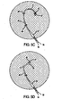
- the plurality of openings 26 also may be located along the side 98 of the distal end region 22 of the lumen in a manner whereby all of the plurality of openings 26 are located on the inside of the coiled distal end region 22 of the lumen.
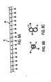
- FIG. 8A which extends the coil for exemplary purposes only, illustrates this embodiment.
- a distal opening 26, optionally may be included at the end 96 of the distal end region 22 of the lumen 14.
- the lumens 12, 14 each may have a "D" shape. However, it is within the scope of the invention to have lumens 12, 14 that are round in shape, as seen in FIG. 8C .
- the lumen 12, 14 shapes as shown in Figs. 8B and 8C are intended to be exemplary only of the variety of lumen shapes that can be used with the present invention. It will be understood, based on this disclosure, that the present invention is not limited to the configurations shown is Figs. 8B and 8C .
- the lumens each may have shapes and sizes that vary from the other lumen or lumens.
- a radiopaque strip 94 may be included in the lumen wall 90 of either the short lumen 12 or the long lumen 14 to distinguish the lumens from one another, particularly at their proximal ends 16,18.
- the radiopaque strip 94 will be placed in the long lumen 14 as the longer length enables the user to more readily identify the radiopaque strip 94.
- FIGS. 1A through 1E , 2A through 2D, 4, 5A and 5B which illustrate a diffuser 30.
- the diffuser 30 may be added to the catheter 10 and located over the at least one distal opening 24 in the short lumen 12.
- the long lumen 14 extends beyond the diffuser 30 more distally into the body of the user of the catheter. As seen most clearly in FIGS. 1C-1,1C-2, and 4, the long lumen 14 may extend through the diffuser 30.
- the long lumen 14 is "D" shaped.
- the long lumen 14 has a round shape.
- the diffuser 30 has an interior portion 32 and an exterior portion 34 and at least one opening 36 between the interior portion 32 and the exterior portion 34.
- the matter 42 being dispensed in the body of the user flows through the short lumen 12 and into the diffuser 30 at the distal end opening 24 of the lumen 12. Thereafter, the matter 42 flows through the at least one opening 36 of the diffuser and into the body of the user.
- the diffuser 30 may have a plurality of openings 36 through which the matter 42 enters the body of the user in a diffused manner.
- the plurality of openings 36 may be located radially around the sides of the diffuser 30 in a generally perpendicular manner to the longitudinal axis of the catheter 10.
- the catheter 10 of the current invention may be used for continuous flow peritoneal dialysis.
- the matter 42 flowing through the catheter may be dialysate.
- the diffuser 30 of the current invention enables a gentle interaction on the peritoneal structures from the effects of high dialysate flow rates, and enables the dialysate solution to readily mix into the peritoneal cavity 40.
- the radially located openings 36 allow dialysate 42 to exit perpendicularly generally 360 degrees from the diffuser.
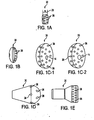
- FIGS. 1A through 1E illustrate various shapes in which a diffuser 30 may be formed.
- FIG. 1A illustrates a cylindrical shape
- FIG.1B illustrates an oval and/or round shape
- FIG. 1C-1 illustrates a semi-oval shape
- Fig. 1C-2 illustrates a semi-round shape
- FIG. 1D illustrates a teardrop shape
- FIG. 1E illustrates a bell shape.
- a diffuser 30 may be made of combinations of the shapes illustrated in FIGS. 1A - 1E .
- the diffuser 30 configurations as shown in FIGS. 1A through 1E are intended to be exemplary only of the variety of configurations achievable with the present invention. It will be understood, based on this disclosure, that the present invention is not limited to the configurations shown in FIGS. 1A through 1E .
- the diffuser 30 When used for continuous flow peritoneal dialysis, the diffuser 30 provides even disbursement of the dialysate 42.
- the plurality of openings 36 diffuse the delivery pressure of the dialysate 42, which can provide a gentle interaction on the peritoneal membrane 38.
- the dimensions of the invention may be varied for different size catheters, embodiments, and different characteristics unique to the user of the catheter.
- Examples of dimensions that may be used include the following: the proximal end of the diffuser 30 may be located less than 1mm from the peritoneal membrane 38. Also, the distance between the distal end of the diffuser 30 and the beginning of the spiral at the distal end region 22 of the long lumen 14 may be approximately 15 cm in length. While the length of the spiral distal end region 22 of the long lumen 14 may vary, its length may be approximately 8.875 inches. Lumen resistance may yield in the range of 100 to 300 ml/min. When the diffuser 30 is cylindrical in shape, the width 28 of the cylinder 1Al may be .5 cm long. While any number of openings 36 can be used, diffusers 30 may have openings in numbers ranging from six to twenty-four. It is to be understood that these dimensions are exemplary only, and are not to be taken as limitations on the invention.
- the interior portion 32 of the diffuser 30 may have a proximal bonding region 82 and a distal bonding region 84, which are regions onto which the lumen wall 90 of the long lumen 14 may be bonded to the diffuser 32.
- the bonding may be accomplished by means of glue, adhesive, heat bonding, or other means currently known in the art or to be discovered.
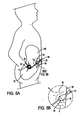
- FIG. 5A shows the general location of the catheter 10 in the peritoneum 100, when the catheter 10 is used for continuous flow peritoneal dialysis.
- the diffuser 30 is located just distally to the peritoneal membrane 38.
- the coiled distal end region 22 of the long lumen 14 is located in the lower Douglas cavity 92 of the peritoneum 100.
- the catheter 10 separates the delivery and return of the dialysate 42. As a result, there is minimal recirculation of the spent dialysate 42.
- the fresh dialysate 42 enters the peritoneum 100 through the diffuser 30.
- the dialysate 42 passes through the peritoneum 100 where the necessary physiological and chemical processes occur, and which turn the fresh dialysate into spent dialysate. Constant intra-peritoneal volume can be maintained with high dialysate flow rates to maintain a high solute concentration gradient between plasma and continuously renewed dialysate solution 42.
- the spent dialysate 42 is aspirated back out of the peritoneum 100 through the at least one opening 26 of the long lumen 14.
- the coiled design of the distal end region 22 of the long lumen 14 increases the bulk tubing which separates the parietal and visceral layers of the peritoneum 100 from obstructing the at least one distal opening 26 for outflow of the spent dialysate 42.
- the use of a plurality of openings 26 can increase the outflow rate.
- the use of a coiled long lumen 14 distal end region 22 is preferred for peritoneal dialysis because it is more gentle to the viscera than the tip of a straight lumen.
- the catheter 10,10' is made of a low durometer silicone.
- Low durometer silicone is preferable because of its biocompatibility and softness, which is beneficial for use in the peritoneum 100, which is a relatively soft body structure.
- low durometer silicone is flexible in a large range of temperatures and has no clinically harmful leachable plasticizers.
- the first lumen 12, the second lumen 14, and additional lumens in catheters having more than two lumens, and diffuser 30 may be made of a biocompatible plastic or elastomer, more preferably from a biocompatible elastomer.
- Suitable biocompatible plastics include materials such as, for example, polyethylene, homopolymers and copolymers of vinyl acetate such as ethylene vinyl acetate copolymer, polyvinylchlorides, homopolymers and copolymers of acrylates such as polymethylmethacrylate, polyethylmethacrylate, polymethacrylate, ethylene glycol dimethacrylate, ethylene dimethacrylate and hydroxymethyl methacrylate, polyurethanes, ployvinylpyrrolidone, 2-pyrrolidone, polyacrylonitrile butadiene, polycarbonates, polyamides, fluoropolymers such as homopolymers and copolymers of polytetrafluoroethylene and polyvinyl fluor
- biocompatible polymeric material includes a polyurethane or a polyolefin polymeric material having a preferably soft durometer, as specified below.
- Suitable, preferred, biocompatible elastomers for use in forming the catheters 10, 10' include biocompatible elastomers such as medical grade silicone rubbers, polyvinyl chloride elastomers, polyolefin homopolymeric and copolymeric elastomers, urethane-based elastomers, and natural rubber or other synthetic rubbers.
- the catheter 10, 10' may be made of the elastomeric material such that they are flexible, durable, soft, and easily conformable to the shape of the area to be catheterized and/or the subcutaneous area and minimize risk of harm to vessel walls.
- the catheter 10,10' may be formed of a soft silicone elastomer which has a hardness of at least about 80-A on a Shore durometer scale.
- a soft silicone elastomer which has a hardness of at least about 80-A on a Shore durometer scale.
- Such an elastomer is available from Dow Corning, and can include 20% barium sulfate in the elastomer to provide radiopacity. While it is preferred to have a higher Shore durometer hardness if a biocompatible elastomer is used, particularly for hemodialysis, it is also possible to make a device from an elastomer having a lower Shore durometer hardness without departing from the spirit of the invention. It will be understood, based on this disclosure, that the catheter 10, 10' may also be radiopaque depending on its intended use.
- FIGS. 2B, 2C, 2D , 3 , 5C, 5D and 6A through 6C show the invention with a hub 50, which is optional.
- a hub 50 When a hub 50 is provided, the proximal ends 16, 18 of the at least two lumens 12,14 are located in the hub 50.
- the lumens 12, 14 may be attached to the hub 50 in a nonremovable manner, as seen in FIG. 2B .
- the lumens 12, 14 may be attached to a detachable hub 50 1 , as seen in FIG. 2C .
- Detachable hubs are disclosed in a pending application, U.S. Provisional Application Serial No.
- FIGS. 2D and 3 the use of all hubs 110 currently known in the art or to be discovered are within the scope of the invention.
- the hub is optional, and the hubs included for exemplary purposes should not be construed as limiting.
- the catheter 10, 10' of the current invention may be used with a hub 50, a detachable hub 50 1 , with no hub, or with hubs 110, or other attachments 110, currently known in the art or to be discovered.
- a nonremovable hub 50 may be utilized.
- the proximal ends 16, 18 of the at least two lumens 12, 14 end in the hub 50.
- the distal ends of extenders 56, 58 also end in the hub 50.
- the proximal end openings 102, 104 of the lumens 12, 14 each are “D” shaped.
- the distal openings 106, 108 of the extenders 56, 58 each may have a round shape.
- the extension distal end openings 106, 108 and the proximal end openings, 102,104 of the at least two lumens 12, 14 are brought into fluid communication with each other via hub channels 52, 54 molded in the hub 50.
- the hub 50 is molded around a removable interior pin (not shown) that is round at one end and "D" shaped at the other end.
- the shapes, sizes, and number of the lumens and extenders utilized with the hub 50 are exemplary, and not intended to be limiting.
- the extension proximal ends (not shown) are preferably connected to respective female luer locks (not shown) in a conventional manner.
- the female luer locks may be substituted with any suitable type of quick connect fittings, ferrule connectors, threadable connectors, or any connection means known in the art or to be discovered to achieve the flow of matter through the catheter 10, 10'.
- the extenders as known in the art, may be connected in fluid communication to respective fluid inlets and outlets of the dialysis unit, other fluid transfer equipment, or other apparatus needed to carry out the purpose for the catheter 10,10'.
- the hub 50, 50' and extenders 56, 58 of the catheter 10,10' are optional.
- the catheter 10, 10' of the present invention can be formed simply as at least two lumens 12,14.
- the proximal ends 16,18 of the lumens could be made connectable to dialysis equipment or other apparatus by providing luers or other connectors to the proximal ends 16,18 of the lumens without a hub or additional extenders.
- the hub 50 When the catheter 10,10' has a hub 50 that is not detachable, generally, the hub 50 will be passable through the subcutaneous layer 48 of body of the user of the catheter. As seen in FIGS. 5C and 5D , the proximal ends 16, 18, hub 50 and extenders 56, 58 , may be passed through a subcutaneous tunnel in the subcutaneous layer 48 of the body using various tunneling techniques. The proximal ends 16, 18, hub 50 and extenders 56, 58 may be inserted in a tunnel entrance incision 86 and tunneled through the subcutaneous layer 48 to the tunnel exit incision 86.
- the lumen proximal ends 16, 18, the hub 50 and the extenders 56, 58 may be inserted in the catheter entrance incision 110 and tunneled through the subcutaneous layer 48 to a tunnel exit incision 86.
- the catheters 10, 10' that do not have hubs or that have detachable hubs 50 ', the lumen proximal ends 16, 18 may be subcutaneously tunneled.
- FIGS. 2A through 2D , 3, 4, and 5A - 5D illustrate the inclusion of at least one cuff 44, which is optional.
- a second cuff 46 may also be included, which is optional.
- the at least one cuff 44 is made of a material, generally polyester, onto which the tissue of the user of the catheter may grow in order to secure the catheter 10, 10' to the body of the user.
- a cuff 44 is located just proximally to the peritoneal membrane 38, when the catheter 10, 10' is used for continuous flow peritoneal dialysis.
- the cuff 44 may be located between 0 and 5 mm proximally from the peritoneal membrane 38.
- the space between the diffuser 30 and the cuff 44 will be in the range of between .5 and 10 mm.
- the range of distance between the first cuff 44 and the second cuff 46 preferably will be 10 cm. It is to be understood that the dimensions of the cuffs 44, 46 may be varied for different size catheters, embodiments, and different characteristics unique to the user of the catheter. The dimensions listed are not intended to be limiting, rather they are included for exemplary purposes.
- a second cuff 46 may located under the skin distally to the exit hole 86 for the catheter 10,10'.
- FIG. 7 is a flowchart for the method for continuous flow peritoneal dialysis of the current invention.
- the method includes creating an incision in the body of the user and separating anatomical layers until the peritoneum is found 62; making a circular suture in the peritoneal membrane 64; inserting the distal end of the catheter into the Douglas cavity of the peritoneum, guided by a semi-rigid wire inside the outflow lumen, and tightening the parietal peritoneum between the diffuser and cuff by tightening the circular suture in the peritoneal membrane 68.
- the method may include, anesthetizing under the skin down to the peritoneal surface with a syringe 60.
- the method may include making a lateral incision in the skin of the user 70; creating a subcutaneous tunnel, also known as a skin tunnel 72; passing the proximal end of the catheter subcutaneously through the skin tunnel 74, which may be accomplished by means of a tunneler; attaching connecting attachments to the lumens 76; and suturing the incision in the skin 78.
- the method may also include providing a catheter 10 that has a diffuser 30.
- the incision of step 62 may be about 3 cm long, and the incision of step 70 may be about 10 cm long. It is to be understood that the dimensions of the incisions may be varied for different size catheters, embodiments, and different characteristics unique to the user of the catheter. The dimensions listed are not intended to be limiting, rather they are included for exemplary purposes.
- a sheath (not shown), as commonly known in the art, may be inserted over the diffuser before insertion of the catheter 10 into the body. Because the diffuser 30 preferably is made of a low durometer silicone, it may be easily compressed into the optional sheath. The sheath diminishes the volume of the diffuser 30, which may enable the insertion of the catheter 10, including the diffuser 30, utilizing a smaller incision than would be possible without use of a sheath.
- a Quill sheath is commonly known in the art, and may be used for a catheter 10 that does not have a hub. If the catheter 10 has a hub 50, which is not removable, a tear-away sheath, which is commonly known in the art, may be used.
- the subcutaneous layer 48 When a catheter 10, 10' having a hub 50 which is not detachable is passed through the skin tunnel subcutaneously 76, the subcutaneous layer 48 will have to stretch to enable the hub 50 to pass. Normally, the elasticity of the subcutaneous layer 48 will enable the subcutaneous tissue to encapsulate the lumens 12, 14 after passage of the hub 50.
- a detachable hub 50 1 When a detachable hub 50 1 is utilized on the catheter 10, 10', the hub 50 1 is among the attachments connected to the catheter during the step 76 of connecting attachments to the catheter.
- the open ends of the luer locks may be connected in fluid communication to respective fluid inlets and outlets of the dialysis unit, or other fluid transfer equipment in order to begin dialysis.
Abstract
Description
- The current invention relates generally to diffusers for a catheter.
- Continuous flow peritoneal dialysis is a technique which utilizes a certain amount of fluid, generally dialysate, which is constantly present in the abdomen. Continuous flow peritoneal dialysis previously known in the art has utilized two single lumen peritoneal dialysis catheters or a modified large bore hemodialysis catheter. The inflow and uptake catheters enable the inflow and outflow to remain constant. However, high dialysate flow rates and re-circulation due to channeling or poor mixing inside the peritoneal cavity are problems associated with continuous flow peritoneal dialysis.
- In the continuous flow peritoneal dialysis technique, the peritoneal dialysis solution is either utilized in a single pass or a re-circulation loop. Various re-circulation systems, such as sorbent cartridges or dialyzers, are known. A problem has been the quick drainage of fresh solution before coming into contact with the peritoneal exchange surface.
- Regeneration systems include utilizing a batch of moderate volume prepared fluid and recirculating the fluid until it saturates. Another method provides an initial fixed volume of commercial dialysis solution for priming, followed by continuous regeneration of the spent dialysate. Regeneration can be performed either by a hemodialysis filter or by absorption. Another method is preparation of solutions from water in concentrate with on-line ultra-filtration.
- The proximal ends of the two lumens are attached to a dialysate regeneration means, which are well known in the art. Regenerated dialysate, or fresh dialysate, are introduced into the abdomen through one of the catheters, which is connected to a means for providing regenerated or fresh dialysate, which is well known in the art.
- For all of the aforementioned reasons, it is important to have a continuous flow peritoneal dialysis catheter and method which effectively allow the dialysate to mix into the peritoneum while reducing trauma to the peritoneal walls. It is important to have catheters, and diffusers for catheters, that gently dispense the matter flowing through the catheter.
- The current invention relates to diffusers for a catheter according to independent claim 1. The diffuser has an interior portion and an exterior portion and at least one opening for the dispensing of matter into the body of the user. In addition, the diffuser may have a plurality of openings through which the matter may be dispensed into the body of the user in a diffused manner. The plurality of openings may be located radially around the sides of the diffuser in a generally perpendicular manner to the longitudinal axis of the catheter. The shapes of the diffuser generally consist of cylindrical, teardrop, bell, round, oval, semi-round, semi-oval and a combination of shapes. Moreover, the invention relates to catheters having a diffuser according to the invention. The diffuser, and catheter having a diffuser, may be used on a catheter used for a continuous flow peritoneal dialysis.
- Continuous flow catheters having a diffuser according to the invention are described, wherein the catheters may have at least two lumens, one of which is a short lumen, and the other of which is a long lumen. The long lumen, which is the uptake lumen, is coiled. It may have a plurality of openings, generally located on the inside of the coil, for the intake of matter flowing through the catheter. The catheter includes a diffuser, which is located over the distal end of the short lumen, for dispensing matter into the body of the user. The long lumen may extend beyond, and/or through, the diffuser. The catheter may also include a hub at the proximal ends of the at least two lumens. The hub may be passable subcutaneously through the body of the user of the catheter, or the hub may be detachable. The catheter may be used for peritoneal dialysis. In addition, the catheter may include at least one cuff located proximally to the peritoneal membrane for the adherence of subcutaneous tissue. The catheter may contain lumens which are "D" shaped.
- Furthermore, methods for a continuous flow peritoneal dialysis are described, which include the steps of creating an incision in the body of the user and separating the anatomical layers, making a circular suture in the peritoneal membrane, making an incision in the peritoneal membrane, inserting the catheter, and tightening the parietal peritoneum. The method also may include anesthetizing the skin and peritoneal surface. In addition, the method may include making a lateral incision in the skin of the user, creating a skin tunnel, passing the catheter through the skin tunnel, connecting attachments to the catheter, and suturing the skin incision. The method may also include providing a catheter having a diffuser.
- The accompanying drawings, which are incorporated in and form a part of the specification, illustrate the embodiments of the present invention, and together with the description, serve to explain the principles of the invention. In the drawings, the same reference numerals are employed for designating the same elements throughout the several figures.
-
FIG. 1A is a perspective view of a cylindrically shaped diffuser; -
FIG. 1B is a side elevational view of a round and/or oval diffuser; -
FIG. 1C-1 is a perspective view of a semi-oval shaped diffuser having a "D" shaped long lumen; -
FIG. 1C-2 is a perspective view of a semi-round shaped diffuser having a round shaped long lumen; -
FIG. 1D is a perspective view of a teardrop shaped diffuser; -
FIG. 1E is a side elevational view of a bell shaped diffuser; -
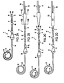
FIG. 2A is a top elevational view of a catheter with a diffuser and with no hub; -
FIG. 2B is a top elevational view of a catheter with a diffuser and a hub; -
FIG. 2C is a top elevational view of a catheter with a diffuser and a detachable hub; -
FIG. 2D is a top elevational view of a catheter with a diffuser and with an optional hub of any kind; -
FIG. 3 is a top elevational view of a catheter without a diffuser and with an optional hub of any kind; -
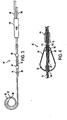
FIG. 4 is a cross section of a diffuser; -
FIG. 5A shows the catheter in utility; -
FIG. 5B is a view of the diffuser in utility; -
FIG. 5C is a view of a tunneled proximal end; -
FIG. 5D is a view of a tunneled proximal end; -
FIG. 6A is a cross section of a hub; -
FIG. 6B is a cross section of the double "D" lumens in the hub; -
FIG. 6C is a cross section of the extenders in the hub; -
FIG. 7 is a flow chart of a method for continuous flow peritoneal dialysis; -
FIG. 8A is a side view of the long lumen extended; -
FIG. 8B is a cross section showing two double "D" shaped lumens; and -
FIG. 8C is a cross section showing two round shaped lumens. - In describing embodiments of the invention illustrated in the drawings, specific terminology will be used for the sake of clarity. However, the invention is not intended to be limited to the specific terms so selected, and it is to be understood that each specific term includes all technical equivalents which operate in a similar manner to accomplish a similar purpose. The words "proximal," "distal," "short" and "long" are used herein for exemplary purposes, and are not to be taken as a limitation on the present invention. The words "proximal" and "distal" refer to directions away from and closer to, respectively, the insertion tips of the first and second lumens according to the present invention. The words "short" and "long" designate the length of lumens relative to one another.
- Reference is now made to
FIGS. 2A, 2B, 2C, 2D , and3 which show thecatheter 10, 10' of the current invention. As seen in these figures, the catheter contains at least two lumens, afirst lumen 12 and asecond lumen 14. Thesecond lumen 14 is longer than thefirst lumen 12. For explanatory purposes, thesecond lumen 14 also is referred to as along lumen 14 and thefirst lumen 12 also is referred to as ashort lumen 12. Each lumen has aproximal end lumens matter 42 into or out of the body of the user of thecatheter 10,10'.Matter 42 passes through thelongitudinal lumen channel 112 defined by thelumen wall 90. - The
catheter 10,10' of the present invention can be adapted for use in various applications in which bodily fluids, medicaments or other solutions are introduced into and removed from the body such as perfusion, infusion, plasmapheresis, hemodialysis, chemotherapy, and the like. The area to be catherized may be the peritoneum, and may be any suitable area within the body. Other areas in which thecatheter 10, 10' may be used include, for example, any abscess cavity, post-operative cavity, and other areas of the body including inter-abdominal, sub-diaphragmatic and sub-hepatic areas. It should be understood by one of ordinary skill in the art from this disclosure that these areas are exemplary, and that thecatheter 10, 10' may be used to remove or introduce matter in various areas to be catherized. In addition, it will be understood by one skilled in the art based on this disclosure, that thecatheter 10,10' can be configured and adapted by increasing or decreasing the catheter size and/or number of catheters and/or lumens such that thecatheter 10,10' can be beneficially used for other medical applications in which matter is introduced into and/or removed from the body. -
Matter 42 may pass into the body of the user of the catheter through theshort lumen 12, which also can be referred to as the delivery lumen. Matter may be removed from the body of the user of thecatheter 10 through thelong lumen 14, which also can be referred to as the uptake or return lumen. However, it is to be understood that within the scope of the invention thelong lumen 14 also may be a delivery lumen and theshort lumen 12 may be an uptake lumen. - The
long lumen 14 can be coiled and has at least oneopening 26 for the passage of matter through the lumen. The at least oneopening 26 can be at thedistal end 96 of thelumen 14. In addition, it is within the scope of this invention to place the at least onedistal opening 26 along theside 98 of thedistal end region 22 of thelong lumen 14. - The
long lumen 14 may have a plurality ofopenings 26 along theside 98 of thedistal end region 22 of the lumen. - The plurality of
openings 26 also may be located along theside 98 of thedistal end region 22 of the lumen in a manner whereby all of the plurality ofopenings 26 are located on the inside of the coileddistal end region 22 of the lumen.FIG. 8A , which extends the coil for exemplary purposes only, illustrates this embodiment. In addition, adistal opening 26, optionally may be included at theend 96 of thedistal end region 22 of thelumen 14. - As seen in
FIG. 8B , thelumens lumens FIG. 8C . Thelumen Figs. 8B and 8C are intended to be exemplary only of the variety of lumen shapes that can be used with the present invention. It will be understood, based on this disclosure, that the present invention is not limited to the configurations shown isFigs. 8B and 8C . One skilled in the art will appreciate that all shapes of the lumens known in the art to be discovered are within scope of the invention. In addition, the lumens each may have shapes and sizes that vary from the other lumen or lumens. - Optionally, as known in the art, a
radiopaque strip 94 may be included in thelumen wall 90 of either theshort lumen 12 or thelong lumen 14 to distinguish the lumens from one another, particularly at their proximal ends 16,18. Generally, theradiopaque strip 94 will be placed in thelong lumen 14 as the longer length enables the user to more readily identify theradiopaque strip 94. - Reference is know made to
FIGS. 1A through 1E , 2A through 2D, 4, 5A and 5B , which illustrate adiffuser 30. It is to be noted that the embodiment of the catheter 10' that is illustrated inFig. 3 does not contain a diffuser. Thediffuser 30 may be added to thecatheter 10 and located over the at least onedistal opening 24 in theshort lumen 12. Thelong lumen 14 extends beyond thediffuser 30 more distally into the body of the user of the catheter. As seen most clearly inFIGS. 1C-1,1C-2, and 4, thelong lumen 14 may extend through thediffuser 30. InFIG. 1C-1, thelong lumen 14 is "D" shaped. InFIG. 1C-2 , thelong lumen 14 has a round shape. - The
diffuser 30 has aninterior portion 32 and anexterior portion 34 and at least oneopening 36 between theinterior portion 32 and theexterior portion 34. Thematter 42 being dispensed in the body of the user flows through theshort lumen 12 and into thediffuser 30 at the distal end opening 24 of thelumen 12. Thereafter, thematter 42 flows through the at least oneopening 36 of the diffuser and into the body of the user. - The
diffuser 30 may have a plurality ofopenings 36 through which thematter 42 enters the body of the user in a diffused manner. In addition, the plurality ofopenings 36 may be located radially around the sides of thediffuser 30 in a generally perpendicular manner to the longitudinal axis of thecatheter 10. - The
catheter 10 of the current invention may be used for continuous flow peritoneal dialysis. In peritoneal dialysis, thematter 42 flowing through the catheter may be dialysate. Thediffuser 30 of the current invention enables a gentle interaction on the peritoneal structures from the effects of high dialysate flow rates, and enables the dialysate solution to readily mix into theperitoneal cavity 40. When used for continuous flow peritoneal dialysis, the radially locatedopenings 36 allowdialysate 42 to exit perpendicularly generally 360 degrees from the diffuser. -
FIGS. 1A through 1E illustrate various shapes in which adiffuser 30 may be formed.FIG. 1A illustrates a cylindrical shape,FIG.1B illustrates an oval and/or round shape,FIG. 1C-1 illustrates a semi-oval shape,Fig. 1C-2 illustrates a semi-round shape,FIG. 1D illustrates a teardrop shape andFIG. 1E illustrates a bell shape. In addition, adiffuser 30 may be made of combinations of the shapes illustrated inFIGS. 1A - 1E . Thediffuser 30 configurations as shown inFIGS. 1A through 1E are intended to be exemplary only of the variety of configurations achievable with the present invention. It will be understood, based on this disclosure, that the present invention is not limited to the configurations shown inFIGS. 1A through 1E . - When used for continuous flow peritoneal dialysis, the
diffuser 30 provides even disbursement of thedialysate 42. The plurality ofopenings 36 diffuse the delivery pressure of thedialysate 42, which can provide a gentle interaction on theperitoneal membrane 38. - It is to be understood that the dimensions of the invention may be varied for different size catheters, embodiments, and different characteristics unique to the user of the catheter. Examples of dimensions that may be used include the following: the proximal end of the
diffuser 30 may be located less than 1mm from theperitoneal membrane 38. Also, the distance between the distal end of thediffuser 30 and the beginning of the spiral at thedistal end region 22 of thelong lumen 14 may be approximately 15 cm in length. While the length of the spiraldistal end region 22 of thelong lumen 14 may vary, its length may be approximately 8.875 inches. Lumen resistance may yield in the range of 100 to 300 ml/min. When thediffuser 30 is cylindrical in shape, thewidth 28 of the cylinder 1Al may be .5 cm long. While any number ofopenings 36 can be used,diffusers 30 may have openings in numbers ranging from six to twenty-four. It is to be understood that these dimensions are exemplary only, and are not to be taken as limitations on the invention. - As clearly illustrated in
FIG. 4 , theinterior portion 32 of thediffuser 30 may have aproximal bonding region 82 and adistal bonding region 84, which are regions onto which thelumen wall 90 of thelong lumen 14 may be bonded to thediffuser 32. The bonding may be accomplished by means of glue, adhesive, heat bonding, or other means currently known in the art or to be discovered. - Reference is now made to
FIG. 5A , which shows the general location of thecatheter 10 in theperitoneum 100, when thecatheter 10 is used for continuous flow peritoneal dialysis. Thediffuser 30 is located just distally to theperitoneal membrane 38. The coileddistal end region 22 of thelong lumen 14 is located in thelower Douglas cavity 92 of theperitoneum 100. In use, thecatheter 10 separates the delivery and return of thedialysate 42. As a result, there is minimal recirculation of the spentdialysate 42. In use, thefresh dialysate 42 enters theperitoneum 100 through thediffuser 30. Thedialysate 42 passes through theperitoneum 100 where the necessary physiological and chemical processes occur, and which turn the fresh dialysate into spent dialysate. Constant intra-peritoneal volume can be maintained with high dialysate flow rates to maintain a high solute concentration gradient between plasma and continuously reneweddialysate solution 42. The spentdialysate 42 is aspirated back out of theperitoneum 100 through the at least oneopening 26 of thelong lumen 14. - The coiled design of the
distal end region 22 of thelong lumen 14 increases the bulk tubing which separates the parietal and visceral layers of theperitoneum 100 from obstructing the at least onedistal opening 26 for outflow of the spentdialysate 42. The use of a plurality ofopenings 26 can increase the outflow rate. The use of a coiledlong lumen 14distal end region 22 is preferred for peritoneal dialysis because it is more gentle to the viscera than the tip of a straight lumen. - Preferably, the
catheter 10,10' is made of a low durometer silicone. However polyurethane or other biocompatible materials known in the art or to be developed may also be used. Low durometer silicone is preferable because of its biocompatibility and softness, which is beneficial for use in theperitoneum 100, which is a relatively soft body structure. In addition, low durometer silicone is flexible in a large range of temperatures and has no clinically harmful leachable plasticizers. - The
first lumen 12, thesecond lumen 14, and additional lumens in catheters having more than two lumens, anddiffuser 30 may be made of a biocompatible plastic or elastomer, more preferably from a biocompatible elastomer. Suitable biocompatible plastics include materials such as, for example, polyethylene, homopolymers and copolymers of vinyl acetate such as ethylene vinyl acetate copolymer, polyvinylchlorides, homopolymers and copolymers of acrylates such as polymethylmethacrylate, polyethylmethacrylate, polymethacrylate, ethylene glycol dimethacrylate, ethylene dimethacrylate and hydroxymethyl methacrylate, polyurethanes, ployvinylpyrrolidone, 2-pyrrolidone, polyacrylonitrile butadiene, polycarbonates, polyamides, fluoropolymers such as homopolymers and copolymers of polytetrafluoroethylene and polyvinyl fluoride, polystyrenes, homopolymers and copolymers of styrene acrylonitrile, cellulose acetate, homopolymers and copolymers of acrylonitrile butadiene styrene, polymethylpentene, polysulfones, polyesters, polyimides, polyisobutylene, polymethylstyrene and other similar compounds known to those skilled in the art. It should be understood that these possible biocompatible polymers are included above for exemplary purposes and should not be construed as limiting. If a biocompatible polymeric material is used to form thecatheter 10, 10' it is most preferred that the polymeric material includes a polyurethane or a polyolefin polymeric material having a preferably soft durometer, as specified below. - Suitable, preferred, biocompatible elastomers for use in forming the
catheters 10, 10' include biocompatible elastomers such as medical grade silicone rubbers, polyvinyl chloride elastomers, polyolefin homopolymeric and copolymeric elastomers, urethane-based elastomers, and natural rubber or other synthetic rubbers. Thecatheter 10, 10' may be made of the elastomeric material such that they are flexible, durable, soft, and easily conformable to the shape of the area to be catheterized and/or the subcutaneous area and minimize risk of harm to vessel walls. If thecatheter 10,10' is used for hemodialysis applications, they may be formed of a soft silicone elastomer which has a hardness of at least about 80-A on a Shore durometer scale. Such an elastomer is available from Dow Corning, and can include 20% barium sulfate in the elastomer to provide radiopacity. While it is preferred to have a higher Shore durometer hardness if a biocompatible elastomer is used, particularly for hemodialysis, it is also possible to make a device from an elastomer having a lower Shore durometer hardness without departing from the spirit of the invention. It will be understood, based on this disclosure, that thecatheter 10, 10' may also be radiopaque depending on its intended use. - Reference is now made to
FIGS. 2B, 2C, 2D ,3 ,5C, 5D and6A through 6C, which show the invention with ahub 50, which is optional. When ahub 50 is provided, the proximal ends 16, 18 of the at least twolumens hub 50. Thelumens hub 50 in a nonremovable manner, as seen inFIG. 2B . Alternatively, thelumens detachable hub 501 , as seen inFIG. 2C . Detachable hubs are disclosed in a pending application,U.S. Provisional Application Serial No. 60/329,593 , entitled "Detachable Hub," which is incorporated herein by reference. In addition, as illustrated inFIGS. 2D and3 , the use of allhubs 110 currently known in the art or to be discovered are within the scope of the invention. However, as illustrated inFIG. 2A , the hub is optional, and the hubs included for exemplary purposes should not be construed as limiting. One skilled in the art will appreciate that thecatheter 10, 10' of the current invention may be used with ahub 50, adetachable hub 501, with no hub, or withhubs 110, orother attachments 110, currently known in the art or to be discovered. - In an embodiment of the invention, as seen in
FIG. 2B ,5C ,5D and6A - 6C, anonremovable hub 50 may be utilized. As seen in these figures, the proximal ends 16, 18 of the at least twolumens hub 50. In addition, the distal ends ofextenders hub 50. In this embodiment, when thelumens proximal end openings lumens FIGS. 6A through 6C , thedistal openings 106, 108 of theextenders distal end openings 106, 108 and the proximal end openings, 102,104 of the at least twolumens hub channels hub 50. Thehub 50 is molded around a removable interior pin (not shown) that is round at one end and "D" shaped at the other end. The shapes, sizes, and number of the lumens and extenders utilized with thehub 50 are exemplary, and not intended to be limiting. The extension proximal ends (not shown) are preferably connected to respective female luer locks (not shown) in a conventional manner. If decided, the female luer locks may be substituted with any suitable type of quick connect fittings, ferrule connectors, threadable connectors, or any connection means known in the art or to be discovered to achieve the flow of matter through thecatheter 10, 10'. The extenders, as known in the art, may be connected in fluid communication to respective fluid inlets and outlets of the dialysis unit, other fluid transfer equipment, or other apparatus needed to carry out the purpose for thecatheter 10,10'. - As previously mentioned, the
hub 50, 50' andextenders catheter 10,10' are optional. Thecatheter 10, 10' of the present invention can be formed simply as at least twolumens - When the
catheter 10,10' has ahub 50 that is not detachable, generally, thehub 50 will be passable through thesubcutaneous layer 48 of body of the user of the catheter. As seen inFIGS. 5C and 5D , the proximal ends 16, 18,hub 50 andextenders subcutaneous layer 48 of the body using various tunneling techniques. The proximal ends 16, 18,hub 50 andextenders subcutaneous layer 48 to the tunnel exit incision 86. Alternatively, the lumen proximal ends 16, 18, thehub 50 and theextenders catheter entrance incision 110 and tunneled through thesubcutaneous layer 48 to a tunnel exit incision 86. In like manners, thecatheters 10, 10' that do not have hubs or that have detachable hubs 50', the lumen proximal ends 16, 18 may be subcutaneously tunneled. - Reference is now made to
FIGS. 2A through 2D , 3, 4, and 5A - 5D , which illustrate the inclusion of at least onecuff 44, which is optional. In addition, asecond cuff 46 may also be included, which is optional. The at least onecuff 44, as known in the art, is made of a material, generally polyester, onto which the tissue of the user of the catheter may grow in order to secure thecatheter 10, 10' to the body of the user. Acuff 44 is located just proximally to theperitoneal membrane 38, when thecatheter 10, 10' is used for continuous flow peritoneal dialysis. Thecuff 44 may be located between 0 and 5 mm proximally from theperitoneal membrane 38. If theperitoneal membrane 38 is sutured at the incision site of thecatheter 10, 10', added space may be needed because the suture, when pulled, may create folds in themembrane 38. Preferably, the space between thediffuser 30 and thecuff 44 will be in the range of between .5 and 10 mm. The range of distance between thefirst cuff 44 and thesecond cuff 46, preferably will be 10 cm. It is to be understood that the dimensions of thecuffs - As seen in
FIG. 5C , asecond cuff 46 may located under the skin distally to the exit hole 86 for thecatheter 10,10'. - Reference is now made to
FIG. 7 , which is a flowchart for the method for continuous flow peritoneal dialysis of the current invention. The method includes creating an incision in the body of the user and separating anatomical layers until the peritoneum is found 62; making a circular suture in theperitoneal membrane 64; inserting the distal end of the catheter into the Douglas cavity of the peritoneum, guided by a semi-rigid wire inside the outflow lumen, and tightening the parietal peritoneum between the diffuser and cuff by tightening the circular suture in theperitoneal membrane 68. In addition, the method may include, anesthetizing under the skin down to the peritoneal surface with asyringe 60. Also, the method may include making a lateral incision in the skin of the user 70; creating a subcutaneous tunnel, also known as askin tunnel 72; passing the proximal end of the catheter subcutaneously through theskin tunnel 74, which may be accomplished by means of a tunneler; attaching connecting attachments to thelumens 76; and suturing the incision in theskin 78. - The method may also include providing a
catheter 10 that has adiffuser 30. - The incision of
step 62 may be about 3 cm long, and the incision of step 70 may be about 10 cm long. It is to be understood that the dimensions of the incisions may be varied for different size catheters, embodiments, and different characteristics unique to the user of the catheter. The dimensions listed are not intended to be limiting, rather they are included for exemplary purposes. - A sheath (not shown), as commonly known in the art, may be inserted over the diffuser before insertion of the
catheter 10 into the body. Because thediffuser 30 preferably is made of a low durometer silicone, it may be easily compressed into the optional sheath. The sheath diminishes the volume of thediffuser 30, which may enable the insertion of thecatheter 10, including thediffuser 30, utilizing a smaller incision than would be possible without use of a sheath. A Quill sheath is commonly known in the art, and may be used for acatheter 10 that does not have a hub. If thecatheter 10 has ahub 50, which is not removable, a tear-away sheath, which is commonly known in the art, may be used. - When a
catheter 10, 10' having ahub 50 which is not detachable is passed through the skin tunnel subcutaneously 76, thesubcutaneous layer 48 will have to stretch to enable thehub 50 to pass. Normally, the elasticity of thesubcutaneous layer 48 will enable the subcutaneous tissue to encapsulate thelumens hub 50. When adetachable hub 501 is utilized on thecatheter 10, 10', thehub 501 is among the attachments connected to the catheter during thestep 76 of connecting attachments to the catheter. - As known in the art, the open ends of the luer locks may be connected in fluid communication to respective fluid inlets and outlets of the dialysis unit, or other fluid transfer equipment in order to begin dialysis.
- Although the invention has been described and illustrated by various embodiments, it will be apparent to those of ordinary skill in the art that changes and modifications could be made which clearly fall within the scope of the invention. It is understood, therefore, the invention is intended to be protected broadly within the spirit and scope as defined by the appended claims.
Claims (8)
- In a catheter for the passage of matter to the body of the user of the catheter, a compressible diffuser (30) through which matter is dispensed into the body, wherein the diffuser is disposed about a separate lumen extending through the diffuser.
- The diffuser of claim 1, wherein said diffuser has an interior portion (32) and an exterior portion (34) and at least one opening (36) between said interior portion and said exterior portion, the matter to be dispensed by said catheter entering said diffuser and being dispensed in the body through said at least one opening (36).
- The diffuser of claim 2, wherein said diffuser has a plurality of openings (36) and the matter being dispensed in a diffused manner.
- The diffuser of claim 1, wherein said plurality of openings (36) are located radially around the sides of said diffuser (30).
- The diffuser of claim 1, wherein said diffuser has a shape selected from the group consisting of cylindrical, teardrop, bell, round, oval, semi-round, semi-oval and a combination of shapes.
- The diffuser of claim 1, wherein said diffuser is on a catheter (10) used for peritoneal dialysis.
- The diffuser of claim 6, wherein said dialysis is continuous flow peritoneal dialysis.
- Catheter having a diffuser according to any one of claims 1 to 7.
Applications Claiming Priority (3)
| Application Number | Priority Date | Filing Date | Title |
|---|---|---|---|
| US32751501P | 2001-10-05 | 2001-10-05 | |
| US10/057,340 US6749580B2 (en) | 2001-10-05 | 2002-01-23 | Catheter |
| EP02776128A EP1432462B1 (en) | 2001-10-05 | 2002-10-04 | Catheter |
Related Parent Applications (1)
| Application Number | Title | Priority Date | Filing Date |
|---|---|---|---|
| EP02776128.7 Division | 2002-10-04 |
Publications (1)
| Publication Number | Publication Date |
|---|---|
| EP2289576A1 true EP2289576A1 (en) | 2011-03-02 |
Family
ID=26736364
Family Applications (3)
| Application Number | Title | Priority Date | Filing Date |
|---|---|---|---|
| EP10010959A Withdrawn EP2289576A1 (en) | 2001-10-05 | 2002-10-04 | Catheter diffuser |
| EP02776128A Expired - Lifetime EP1432462B1 (en) | 2001-10-05 | 2002-10-04 | Catheter |
| EP10010960.2A Expired - Lifetime EP2292285B1 (en) | 2001-10-05 | 2002-10-04 | Catheter for peritoneal dialysis |
Family Applications After (2)
| Application Number | Title | Priority Date | Filing Date |
|---|---|---|---|
| EP02776128A Expired - Lifetime EP1432462B1 (en) | 2001-10-05 | 2002-10-04 | Catheter |
| EP10010960.2A Expired - Lifetime EP2292285B1 (en) | 2001-10-05 | 2002-10-04 | Catheter for peritoneal dialysis |
Country Status (8)
| Country | Link |
|---|---|
| US (1) | US6749580B2 (en) |
| EP (3) | EP2289576A1 (en) |
| JP (2) | JP4288165B2 (en) |
| AT (1) | ATE509647T1 (en) |
| AU (1) | AU2002341967A1 (en) |
| ES (1) | ES2643217T3 (en) |
| PT (1) | PT2292285T (en) |
| WO (1) | WO2003030960A2 (en) |
Cited By (1)
| Publication number | Priority date | Publication date | Assignee | Title |
|---|---|---|---|---|
| US9034191B2 (en) | 2010-02-24 | 2015-05-19 | The Regents Of The University Of Michigan | Vibration-assisted dialysis method |
Families Citing this family (80)
| Publication number | Priority date | Publication date | Assignee | Title |
|---|---|---|---|---|
| US6702789B1 (en) | 1997-03-11 | 2004-03-09 | Alcove Medical, Inc. | Catheter having insertion control mechanism and anti-bunching mechanism |
| US6976973B1 (en) * | 2000-10-12 | 2005-12-20 | Baxter International Inc. | Peritoneal dialysis catheters |
| US6911014B2 (en) * | 2001-10-05 | 2005-06-28 | Medical Components, Inc. | Continuous flow peritoneal dialysis catheter |
| US6758836B2 (en) | 2002-02-07 | 2004-07-06 | C. R. Bard, Inc. | Split tip dialysis catheter |
| US6893414B2 (en) * | 2002-08-12 | 2005-05-17 | Breg, Inc. | Integrated infusion and aspiration system and method |
| US7419479B2 (en) * | 2002-11-15 | 2008-09-02 | Radius International Limited Partnership | Catheter |
| US7393339B2 (en) | 2003-02-21 | 2008-07-01 | C. R. Bard, Inc. | Multi-lumen catheter with separate distal tips |
| US20040243095A1 (en) | 2003-05-27 | 2004-12-02 | Shekhar Nimkar | Methods and apparatus for inserting multi-lumen spit-tip catheters into a blood vessel |
| JP2007504860A (en) * | 2003-09-08 | 2007-03-08 | アッシュ・アクセス・テクノロジー・インコーポレーテッド | Anticoagulant indwelling catheter |
| US7594911B2 (en) | 2004-03-18 | 2009-09-29 | C. R. Bard, Inc. | Connector system for a proximally trimmable catheter |
| US7594910B2 (en) | 2004-03-18 | 2009-09-29 | C. R. Bard, Inc. | Catheter connector |
| US8083728B2 (en) | 2004-03-18 | 2011-12-27 | C. R. Bard, Inc. | Multifunction adaptor for an open-ended catheter |
| US7377915B2 (en) | 2004-04-01 | 2008-05-27 | C. R. Bard, Inc. | Catheter connector system |
| US8992454B2 (en) | 2004-06-09 | 2015-03-31 | Bard Access Systems, Inc. | Splitable tip catheter with bioresorbable adhesive |
| US20060004316A1 (en) | 2004-07-02 | 2006-01-05 | Difiore Attilio E | Reduction of recirculation in catheters |
| US7976518B2 (en) | 2005-01-13 | 2011-07-12 | Corpak Medsystems, Inc. | Tubing assembly and signal generator placement control device and method for use with catheter guidance systems |
| US7875019B2 (en) | 2005-06-20 | 2011-01-25 | C. R. Bard, Inc. | Connection system for multi-lumen catheter |
| US9126011B2 (en) * | 2006-03-24 | 2015-09-08 | Merit Medical Systems, Inc. | Anti-clotting indwelling catheter |
| CA2616689A1 (en) * | 2005-07-27 | 2007-02-01 | Galt Medical Corp. | Catheter and tunneling device therefor |
| US20070066964A1 (en) * | 2005-07-27 | 2007-03-22 | Atkins Joseph R | Catheter and Tunneling Device Therefor |
| US8029457B2 (en) * | 2006-03-24 | 2011-10-04 | Aat Catheter Technologies, Llc | Indwelling catheter with anti-clotting features |
| DE602007004718D1 (en) | 2006-03-31 | 2010-03-25 | Bard Inc C R | Catheter with arched transition area |
| US20080082079A1 (en) * | 2006-09-28 | 2008-04-03 | Tyco Healthcare Group Lp | Low profile catheter assembly |
| US9168355B2 (en) * | 2006-09-29 | 2015-10-27 | Covidien Lp | Acute hemodialysis catheter assembly |
| US9402973B2 (en) * | 2007-07-06 | 2016-08-02 | Vital 5, Llc | Constrained fluid delivery device |
| US20090018493A1 (en) * | 2007-07-10 | 2009-01-15 | Ash Stephen R | Implantable catheter assembly |
| AU2007357133B2 (en) * | 2007-07-27 | 2014-08-14 | Fresenius Medical Care Holdings, Inc. | Systems and methods for delivery of peritoneal dialysis (PD) solutions |
| US8500939B2 (en) | 2007-10-17 | 2013-08-06 | Bard Access Systems, Inc. | Manufacture of split tip catheters |
| US8066660B2 (en) | 2007-10-26 | 2011-11-29 | C. R. Bard, Inc. | Split-tip catheter including lateral distal openings |
| US8292841B2 (en) | 2007-10-26 | 2012-10-23 | C. R. Bard, Inc. | Solid-body catheter including lateral distal openings |
| WO2009059220A1 (en) | 2007-11-01 | 2009-05-07 | C.R. Bard, Inc. | Catheter assembly including triple lumen tip |
| US9579485B2 (en) | 2007-11-01 | 2017-02-28 | C. R. Bard, Inc. | Catheter assembly including a multi-lumen configuration |
| US8211053B2 (en) * | 2008-05-13 | 2012-07-03 | Equilibrate, Llc | Interosmolar fluid removal |
| JP2009273609A (en) * | 2008-05-14 | 2009-11-26 | Nippon Sherwood Medical Industries Ltd | Catheter with valve |
| EP2123706A1 (en) * | 2008-05-19 | 2009-11-25 | Evonik Degussa GmbH | Thermoplastic elastomers |
| US9005154B2 (en) * | 2008-09-26 | 2015-04-14 | Covidien Lp | Valved hemodialysis catheter |
| WO2010151825A1 (en) | 2009-06-26 | 2010-12-29 | C. R. Bard, Inc. | Proximally trimmable catheter including pre-attached bifurcation and related methods |
| JP2011050420A (en) * | 2009-08-31 | 2011-03-17 | Nippon Sherwood Medical Industries Ltd | Valved catheter |
| CA2715857A1 (en) | 2009-09-30 | 2011-03-30 | Tyco Healthcare Group Lp | Medical catheter having a design providing low recirculation and reversibility |
| US9265913B2 (en) | 2010-09-22 | 2016-02-23 | Vital 5, Llc | Catheter assembly |
| US9446224B2 (en) | 2010-09-22 | 2016-09-20 | Vital 5, L.L.C. | Barrier catheter |
| US9884165B2 (en) | 2011-02-10 | 2018-02-06 | C. R. Bard, Inc. | Multi-lumen catheter including an elliptical profile |
| US9717883B2 (en) | 2011-02-10 | 2017-08-01 | C. R. Bard, Inc. | Multi-lumen catheter with enhanced flow features |
| JP5713732B2 (en) | 2011-03-08 | 2015-05-07 | 日本コヴィディエン株式会社 | Catheter with valve |
| US9861733B2 (en) | 2012-03-23 | 2018-01-09 | Nxstage Medical Inc. | Peritoneal dialysis systems, devices, and methods |
| JP6049685B2 (en) | 2011-03-23 | 2016-12-21 | ネクステージ メディカル インコーポレイテッド | Peritoneal dialysis disposable unit, controller, peritoneal dialysis system |
| US9028441B2 (en) | 2011-09-08 | 2015-05-12 | Corpak Medsystems, Inc. | Apparatus and method used with guidance system for feeding and suctioning |
| USD679804S1 (en) | 2011-09-22 | 2013-04-09 | Vital 5, Llc | Catheter |
| US8747343B2 (en) | 2011-09-30 | 2014-06-10 | Covidien Lp | Hemodialysis catheter with improved side opening design |
| US9072867B2 (en) | 2011-09-30 | 2015-07-07 | Covidien Lp | Catheter with external flow channel |
| US8845590B2 (en) * | 2012-05-01 | 2014-09-30 | Merit Medical Systems, Inc. | Catheter with distal diffuser |
| US10143822B2 (en) | 2012-07-05 | 2018-12-04 | Covidien Lp | Valved tip catheters |
| US10456518B2 (en) | 2012-08-03 | 2019-10-29 | National University Of Singapore | Arterial cannula which allows perfusion along opposing directions within a cannulated vessel |
| US9155862B2 (en) | 2012-09-28 | 2015-10-13 | Covidien Lp | Symmetrical tip acute catheter |
| US10252023B2 (en) | 2013-01-11 | 2019-04-09 | C. R. Bard, Inc. | Curved catheter and methods for making same |
| US20140200402A1 (en) | 2013-01-16 | 2014-07-17 | Phillip Jack Snoke | Medical Device Introduction Systems and Methods |
| US20170055813A1 (en) | 2013-01-16 | 2017-03-02 | Uvision 360, Inc. | Medical device introduction and imaging system, and associated method |
| USD748252S1 (en) | 2013-02-08 | 2016-01-26 | C. R. Bard, Inc. | Multi-lumen catheter tip |
| CN103191478B (en) * | 2013-04-17 | 2015-07-29 | 江苏康进医疗器材有限公司 | The two bag peritoneal dialysis of doubly-linked is with two-tube |
| US10413645B2 (en) | 2014-05-08 | 2019-09-17 | Nikkiso Co., Ltd. | Suction apparatus for peritoneal cavity fluid perfusion system |
| US10258768B2 (en) | 2014-07-14 | 2019-04-16 | C. R. Bard, Inc. | Apparatuses, systems, and methods for inserting catheters having enhanced stiffening and guiding features |
| US10272227B2 (en) | 2014-11-07 | 2019-04-30 | C. R. Bard, Inc. | Connection system for tunneled catheters |
| CN104383620A (en) * | 2014-11-20 | 2015-03-04 | 上海交通大学医学院附属新华医院 | Novel dual-channel peritoneal dialysis catheter suitable for operation under endoscope |
| US10493232B2 (en) | 2015-07-20 | 2019-12-03 | Strataca Systems Limited | Ureteral catheters, bladder catheters, systems, kits and methods for inducing negative pressure to increase renal function |
| US11541205B2 (en) | 2015-07-20 | 2023-01-03 | Roivios Limited | Coated urinary catheter or ureteral stent and method |
| US11040180B2 (en) | 2015-07-20 | 2021-06-22 | Strataca Systems Limited | Systems, kits and methods for inducing negative pressure to increase renal function |
| US10918827B2 (en) | 2015-07-20 | 2021-02-16 | Strataca Systems Limited | Catheter device and method for inducing negative pressure in a patient's bladder |
| CN108136163B (en) * | 2015-07-20 | 2021-05-04 | 斯卓特凯系统有限责任公司 | Ureteral and bladder catheters and methods of introducing negative pressure to increase renal perfusion |
| US10512713B2 (en) | 2015-07-20 | 2019-12-24 | Strataca Systems Limited | Method of removing excess fluid from a patient with hemodilution |
| US11229771B2 (en) | 2015-07-20 | 2022-01-25 | Roivios Limited | Percutaneous ureteral catheter |
| US10926062B2 (en) | 2015-07-20 | 2021-02-23 | Strataca Systems Limited | Ureteral and bladder catheters and methods of inducing negative pressure to increase renal perfusion |
| US11040172B2 (en) | 2015-07-20 | 2021-06-22 | Strataca Systems Limited | Ureteral and bladder catheters and methods of inducing negative pressure to increase renal perfusion |
| US9861734B2 (en) * | 2016-03-21 | 2018-01-09 | King Saud University | Bifurcated peritoneal catheter |
| US10500331B2 (en) | 2017-08-18 | 2019-12-10 | Ayman H. Al-Jazaeri | Drainage catheter with retractable internal drains |
| US11896782B2 (en) | 2017-08-23 | 2024-02-13 | C. R. Bard, Inc. | Priming and tunneling system for a retrograde catheter assembly |
| US10758214B2 (en) | 2017-11-13 | 2020-09-01 | UVision360, Inc. | Biopsy device and method |
| JP2021516089A (en) | 2018-02-28 | 2021-07-01 | ネクステージ メディカル インコーポレイテッド | Fluid preparation and treatment equipment, methods, and systems |
| US10863886B2 (en) | 2019-05-03 | 2020-12-15 | UVision360, Inc. | Rotatable introducers |
| US10765847B1 (en) | 2019-12-10 | 2020-09-08 | Ayman H. Al-Jazaeri | Single lumen drainage catheter with extendable and retractable drains |
| CN113877017B (en) * | 2021-11-05 | 2023-10-20 | 胡梦思 | Peritoneal dialysis puts tub fixing device |
Citations (2)
| Publication number | Priority date | Publication date | Assignee | Title |
|---|---|---|---|---|
| US4681564A (en) * | 1985-10-21 | 1987-07-21 | Landreneau Michael D | Catheter assembly having balloon extended flow path |
| EP0445502A1 (en) * | 1990-01-05 | 1991-09-11 | Angelo Dr. Catalani | Endotracheal tube incorporating a drug-irrigation device |
Family Cites Families (25)
| Publication number | Priority date | Publication date | Assignee | Title |
|---|---|---|---|---|
| US3707967A (en) | 1970-10-01 | 1973-01-02 | Tecna Corp | Steady flow regenerative peritoneal dialysis system and method |
| US3981299A (en) * | 1971-03-15 | 1976-09-21 | Harry Elmer Murray | Urethral catheter |
| US4437856A (en) | 1981-02-09 | 1984-03-20 | Alberto Valli | Peritoneal catheter device for dialysis |
| US4671795A (en) | 1984-11-19 | 1987-06-09 | Mulchin William L | Permanent/retrievable ureteral catheter |
| US4941872A (en) | 1985-01-22 | 1990-07-17 | C. R. Bard, Inc. | Control handle for surgical irrigation and suction device |
| US4925452A (en) * | 1988-03-08 | 1990-05-15 | Uresil Corporation | Multiple conduit drainage device |
| US4935004A (en) | 1988-12-20 | 1990-06-19 | Henry Ford Health System | Peritoneal dialysis catheter |
| US5057075A (en) | 1989-12-13 | 1991-10-15 | Moncrief Jack W | Method for implanting a catheter |
| AU7253691A (en) * | 1990-01-08 | 1991-08-05 | Curators Of The University Of Missouri, The | Multiple lumen catheter for hemodialysis |
| US5322521A (en) * | 1990-05-30 | 1994-06-21 | Wilk Peter J | Plume evacuation method |
| US5143062A (en) | 1990-10-26 | 1992-09-01 | Mallinckrodt Medical, Inc. | Endotracheal tube having irrigation means |
| US5458582A (en) * | 1992-06-15 | 1995-10-17 | Nakao; Naomi L. | Postoperative anesthetic delivery device and associated method for the postoperative treatment of pain |
| JP3146332B2 (en) * | 1992-12-24 | 2001-03-12 | 允 石崎 | CAPD catheter |
| US5254084A (en) | 1993-03-26 | 1993-10-19 | Geary Gregory L | Peritoneal catheter device for dialysis |
| US5607462A (en) | 1993-09-24 | 1997-03-04 | Cardiac Pathways Corporation | Catheter assembly, catheter and multi-catheter introducer for use therewith |
| US5599304A (en) * | 1994-05-10 | 1997-02-04 | Mount Sinai School Of Medicine Of The City University Of New York | Sinonasal suction apparatus |
| FR2738154B1 (en) | 1995-09-05 | 1997-12-26 | Pourchez Thierry | MULTI-PIPE CATHETER, ESPECIALLY HEMODIALYSIS |
| NL1003226C2 (en) | 1996-05-29 | 1997-12-03 | Cordis Europ | Suction catheter with preformed end section. |
| WO1998017333A2 (en) | 1996-10-22 | 1998-04-30 | Hemocleanse, Inc. | Continuous flow-through peritoneal dialysis (cfpd) method with control of intraperitoneal pressure |
| US5776111A (en) | 1996-11-07 | 1998-07-07 | Medical Components, Inc. | Multiple catheter assembly |
| US6179827B1 (en) * | 1998-03-16 | 2001-01-30 | Chase Medical | Catheter having integral expandable/collapsible lumen |
| US6245039B1 (en) | 1998-10-05 | 2001-06-12 | Vasca, Inc. | Methods and apparatus for performing flow-through peritoneal dialysis |
| US6241710B1 (en) | 1999-12-20 | 2001-06-05 | Tricardia Llc | Hypodermic needle with weeping tip and method of use |
| US6497676B1 (en) * | 2000-02-10 | 2002-12-24 | Baxter International | Method and apparatus for monitoring and controlling peritoneal dialysis therapy |
| US6976973B1 (en) * | 2000-10-12 | 2005-12-20 | Baxter International Inc. | Peritoneal dialysis catheters |
-
2002
- 2002-01-23 US US10/057,340 patent/US6749580B2/en not_active Expired - Lifetime
- 2002-10-04 ES ES10010960.2T patent/ES2643217T3/en not_active Expired - Lifetime
- 2002-10-04 JP JP2003533991A patent/JP4288165B2/en not_active Expired - Lifetime
- 2002-10-04 EP EP10010959A patent/EP2289576A1/en not_active Withdrawn
- 2002-10-04 EP EP02776128A patent/EP1432462B1/en not_active Expired - Lifetime
- 2002-10-04 EP EP10010960.2A patent/EP2292285B1/en not_active Expired - Lifetime
- 2002-10-04 AU AU2002341967A patent/AU2002341967A1/en not_active Abandoned
- 2002-10-04 AT AT02776128T patent/ATE509647T1/en not_active IP Right Cessation
- 2002-10-04 PT PT100109602T patent/PT2292285T/en unknown
- 2002-10-04 WO PCT/US2002/031720 patent/WO2003030960A2/en active Application Filing
-
2009
- 2009-02-10 JP JP2009028732A patent/JP4295355B2/en not_active Expired - Lifetime
Patent Citations (2)
| Publication number | Priority date | Publication date | Assignee | Title |
|---|---|---|---|---|
| US4681564A (en) * | 1985-10-21 | 1987-07-21 | Landreneau Michael D | Catheter assembly having balloon extended flow path |
| EP0445502A1 (en) * | 1990-01-05 | 1991-09-11 | Angelo Dr. Catalani | Endotracheal tube incorporating a drug-irrigation device |
Cited By (1)
| Publication number | Priority date | Publication date | Assignee | Title |
|---|---|---|---|---|
| US9034191B2 (en) | 2010-02-24 | 2015-05-19 | The Regents Of The University Of Michigan | Vibration-assisted dialysis method |
Also Published As
| Publication number | Publication date |
|---|---|
| US6749580B2 (en) | 2004-06-15 |
| EP2292285B1 (en) | 2017-07-12 |
| EP1432462B1 (en) | 2011-05-18 |
| EP1432462A2 (en) | 2004-06-30 |
| ATE509647T1 (en) | 2011-06-15 |
| PT2292285T (en) | 2017-10-19 |
| EP2292285A1 (en) | 2011-03-09 |
| JP2009101207A (en) | 2009-05-14 |
| WO2003030960A2 (en) | 2003-04-17 |
| EP1432462A4 (en) | 2007-07-11 |
| WO2003030960A3 (en) | 2004-03-11 |
| AU2002341967A1 (en) | 2003-04-22 |
| JP4295355B2 (en) | 2009-07-15 |
| JP4288165B2 (en) | 2009-07-01 |
| JP2005505353A (en) | 2005-02-24 |
| ES2643217T3 (en) | 2017-11-21 |
| US20030069534A1 (en) | 2003-04-10 |
Similar Documents
| Publication | Publication Date | Title |
|---|---|---|
| EP2292285B1 (en) | Catheter for peritoneal dialysis | |
| EP1735028B1 (en) | Continuous flow peritoneal dialysis catheter | |
| US6190349B1 (en) | Splittable multiple catheter assembly and methods for inserting the same | |
| USRE40913E1 (en) | Multilumen catheter assembly and methods for making and inserting the same | |
| US5624413A (en) | Method for inserting a multiple catheter assembly | |
| US7066925B2 (en) | Method of using a shielded tip catheter | |
| US7556612B2 (en) | Dual-lumen bi-directional flow catheter | |
| JP4304184B2 (en) | Splittable composite catheter assembly | |
| US20020029994A1 (en) | Kit for inserting a multiple catheter assembly | |
| ES2366676T3 (en) | CATHETER. | |
| WO2007145796A2 (en) | Multi-lumen catheter with protected tip | |
| CA2495687C (en) | Shielded tip catheter | |
| US20070282306A1 (en) | Multi-lumen catheter with protected tip |
Legal Events
| Date | Code | Title | Description |
|---|---|---|---|
| PUAI | Public reference made under article 153(3) epc to a published international application that has entered the european phase |
Free format text: ORIGINAL CODE: 0009012 |
|
| AC | Divisional application: reference to earlier application |
Ref document number: 1432462 Country of ref document: EP Kind code of ref document: P |
|
| AK | Designated contracting states |
Kind code of ref document: A1 Designated state(s): AT BE BG CH CY CZ DE DK EE ES FI FR GB GR IE IT LI LU MC NL PT SE SK TR |
|
| 17P | Request for examination filed |
Effective date: 20110823 |
|
| 17Q | First examination report despatched |
Effective date: 20140120 |
|
| STAA | Information on the status of an ep patent application or granted ep patent |
Free format text: STATUS: THE APPLICATION IS DEEMED TO BE WITHDRAWN |
|
| 18D | Application deemed to be withdrawn |
Effective date: 20140731 |