EP2295829A1 - Improved active vibration insulation system - Google Patents
Improved active vibration insulation system Download PDFInfo
- Publication number
- EP2295829A1 EP2295829A1 EP09011638A EP09011638A EP2295829A1 EP 2295829 A1 EP2295829 A1 EP 2295829A1 EP 09011638 A EP09011638 A EP 09011638A EP 09011638 A EP09011638 A EP 09011638A EP 2295829 A1 EP2295829 A1 EP 2295829A1
- Authority
- EP
- European Patent Office
- Prior art keywords
- signals
- freedom
- actuator
- actuators
- control system
- Prior art date
- Legal status (The legal status is an assumption and is not a legal conclusion. Google has not performed a legal analysis and makes no representation as to the accuracy of the status listed.)
- Granted
Links
- 238000009413 insulation Methods 0.000 title 1
- 238000002955 isolation Methods 0.000 claims abstract description 29
- 238000000034 method Methods 0.000 claims abstract description 27
- 238000013519 translation Methods 0.000 claims description 23
- 230000010355 oscillation Effects 0.000 claims description 10
- 230000008569 process Effects 0.000 claims description 7
- 238000012545 processing Methods 0.000 claims description 7
- 230000001419 dependent effect Effects 0.000 claims description 3
- 230000001105 regulatory effect Effects 0.000 abstract description 12
- 230000033001 locomotion Effects 0.000 description 34
- 230000001133 acceleration Effects 0.000 description 20
- 239000011159 matrix material Substances 0.000 description 20
- 239000012212 insulator Substances 0.000 description 12
- 230000000694 effects Effects 0.000 description 10
- 230000008859 change Effects 0.000 description 4
- 230000001276 controlling effect Effects 0.000 description 4
- 230000008878 coupling Effects 0.000 description 4
- 238000010168 coupling process Methods 0.000 description 4
- 238000005859 coupling reaction Methods 0.000 description 4
- 230000006870 function Effects 0.000 description 4
- 238000012546 transfer Methods 0.000 description 4
- 235000012431 wafers Nutrition 0.000 description 4
- 230000009471 action Effects 0.000 description 3
- 238000001459 lithography Methods 0.000 description 3
- 230000003466 anti-cipated effect Effects 0.000 description 2
- 239000004065 semiconductor Substances 0.000 description 2
- 238000000926 separation method Methods 0.000 description 2
- 239000002918 waste heat Substances 0.000 description 2
- 230000008901 benefit Effects 0.000 description 1
- 230000005540 biological transmission Effects 0.000 description 1
- 238000004364 calculation method Methods 0.000 description 1
- 238000012937 correction Methods 0.000 description 1
- 238000013016 damping Methods 0.000 description 1
- 238000001514 detection method Methods 0.000 description 1
- 238000011161 development Methods 0.000 description 1
- 238000005516 engineering process Methods 0.000 description 1
- 238000004519 manufacturing process Methods 0.000 description 1
- 239000000463 material Substances 0.000 description 1
- 230000000149 penetrating effect Effects 0.000 description 1
- 229920000642 polymer Polymers 0.000 description 1
Images


Classifications
-
- F—MECHANICAL ENGINEERING; LIGHTING; HEATING; WEAPONS; BLASTING
- F16—ENGINEERING ELEMENTS AND UNITS; GENERAL MEASURES FOR PRODUCING AND MAINTAINING EFFECTIVE FUNCTIONING OF MACHINES OR INSTALLATIONS; THERMAL INSULATION IN GENERAL
- F16F—SPRINGS; SHOCK-ABSORBERS; MEANS FOR DAMPING VIBRATION
- F16F15/00—Suppression of vibrations in systems; Means or arrangements for avoiding or reducing out-of-balance forces, e.g. due to motion
- F16F15/02—Suppression of vibrations of non-rotating, e.g. reciprocating systems; Suppression of vibrations of rotating systems by use of members not moving with the rotating systems
- F16F15/023—Suppression of vibrations of non-rotating, e.g. reciprocating systems; Suppression of vibrations of rotating systems by use of members not moving with the rotating systems using fluid means
- F16F15/027—Suppression of vibrations of non-rotating, e.g. reciprocating systems; Suppression of vibrations of rotating systems by use of members not moving with the rotating systems using fluid means comprising control arrangements
Definitions
- the present invention relates to a method for controlling an active vibration isolation system and an active vibration isolation system, in particular for the vibration-isolated storage of lithography equipment, wafer handling systems and / or microscopes, such as scanning microscopes.
- Vibration isolation systems are known and needed in many areas of technology, such as the semiconductor industry.
- the shows DE 69817750 T2 a vibration isolation system, which is provided in particular for the vibration-isolated storage of a lithography device.
- a vibration isolated to be stored load typically includes a table and mounted on the table components, such as manufacturing equipment, mounted on air bearings.
- the table is also called the basic mass.
- a passive vibration isolation system is characterized by a "simple" bearing with the lowest possible mechanical stiffness, in order to reduce the transmission of external vibrations to the load to be isolated.
- An air bearing and a polymer spring element for bearing are two examples of a passive vibration isolation system.
- an active vibration isolation is characterized in that the vibration is actively compensated.
- a movement, which is induced by a vibration, is compensated by a corresponding counter-movement. For example, an acceleration of the mass induced by a vibration is opposed to an equal magnitude acceleration, but with opposite signs. The resulting total acceleration of the load is zero. The load remains at rest or the desired location.
- Active vibration isolation systems therefore have, optionally together with a bearing with as little mechanical rigidity as possible, in addition a control system, which includes a control device and sensors and actuators, with which targeted from the outside penetrating into the system vibrations is counteracted.
- the sensors detect movements of the load to be stored.
- Compensation signals are generated by means of the regulating device, with which the actuators are activated and thus compensation movements are generated.
- hybrid control lines There is the possibility to use digital or analog control lines or even both together.
- air bearings which are also referred to as pneumatic isolators or vibration isolators, are used per system and in particular per base mass to be stored.
- Each of the isolators is used "alone" only for height control. Therefore, because of over-determination, only three of them become one, In particular controllable, valve equipped. For a plane, here the horizontal plane, is already clearly defined by three points of support.
- the fourth isolator is passively fed by one of the three other valves (so-called "master-slave configuration"). Thus only three of the four insulators are then really detected by means of a regulation, the fourth remains passive.
- the present invention has the object to provide a system and a method for active vibration isolation, which at least reduce the disadvantages of the prior art described above.
- the first control system is coupled to the second control system.
- means for merging the first actuator actuating signals which are effective in at least one of the three vertical degrees of freedom Zt, Xr and / or Yr, are provided with the second actuator actuating signals effective in the corresponding degree of freedom.
- the means for merging are executed in a preferred embodiment of the invention as a circuit. This can be designed as an analog and / or a digital circuit.
- the process according to the invention can be carried out in particular by means of the system according to the invention.
- the system according to the invention is in particular designed for carrying out the method according to the invention.
- a vibration compensation is understood to be counteracted by the disturbing movements or vibrations which act on the system. Ideally, the motion or vibration is compensated. This is preferably done in all six degrees of freedom of movement.
- the six degrees of freedom are the three degrees of freedom of translation Xt, Yt and Zt and the three degrees of freedom of rotation Xr, Yr and Zr.
- the coordinates X and Y define the horizontal plane and the coordinate Z the vertical. In general, the horizontal plane is defined by the base ground.
- the sensors detect, indirectly and / or directly, a mass movement of the base mass and / or the load.
- This mass movement is preferably a vibration.
- the mass movement is characterized by an acceleration, a velocity and / or a positional change of the base mass and / or the load. For example, the position of the base mass is dependent on the vibrations acting on it.
- the sensor may be a sensor capable of detecting only the vibrations or a disturbance in one degree of freedom.
- the sensor can also be a sensor which is suitable for detecting the vibrations or a disturbance variable in a plurality of degrees of freedom. Examples of the sensors are geophone sensors and / or piezoelectric sensors. However, the list is only an example and not exhaustive.
- the position sensors in particular for providing the vertical position signals, provide information about a position and / or a position change, preferably the base mass. This can be done directly or indirectly. Preferably, the position, such as the height, is delivered as such and thus directly.
- the position sensors, in particular for providing the vertical position signals may also have further functions. You can also record the acceleration and / or the speed.
- the sensor signals may be analog and / or digital signals.
- a sensor signal may be a signal which detects only the vibrations or a disturbance variable in one degree of freedom.
- the sensor signal may also be a signal that detects the vibrations or a disturbance variable in a plurality of degrees of freedom.
- the actuator control signals can be analog and / or digital signals.
- An actuator control signal represents a kind of compensation signal.
- An oscillation of a load to be stored is actively compensated.
- the actuators can work in one Degree of freedom or be effective in a plurality of degrees of freedom of movement.
- An actuator control signal may therefore be a signal containing information for only one degree of freedom. But it can also be a signal that contains information for a variety of degrees of freedom.
- Examples of the actuators include Lorentz motors, such as plunger coils, and / or piezoelectric actuators. However, the list is only an example and not exhaustive.
- the actuators have an effective range.
- the respective effective range is defined, for example, by the size, the direction and / or the frequency of the actuator actuating signal.
- the pneumatic vibration isolators as second actuators have a force effect in the three vertically effective degrees of freedom Zt, Xr and Yr.
- control device may be a digitally and / or analogously operating control device.
- a first or the first control system is provided for vibration compensation in at least one degree of freedom of translation Xt, Yt and / or Zt and / or in at least one degree of freedom of rotation Xr, Yr and / or Zr. That the first control system is effective in the stated degrees of freedom.
- the first control system operates in all three degrees of freedom of translation Xt, Yt and Zt and in all three degrees of freedom of rotation Xr, Yr and Zr.
- the first control system is at least by the first sensors, the first actuators and a first control device, which is designed for processing the first sensor signals in the first actuator actuating signals provided.
- the first sensors are designed to detect vibrations in at least one degree of freedom of translation Xt, Yt and / or Zt and / or in at least one degree of freedom of rotation Xr, Yr and / or Zr.
- the first sensors operate in all three degrees of freedom of translation Xt, Yt and Zt and in all three degrees of freedom of rotation Xr, Yr and Zr.
- the first actuators for vibration compensation are effective in at least one degree of freedom of translation Xt, Yt and / or Zt and / or in at least one degree of freedom of rotation Xr, Yr and / or Zr.
- the first actuators operate in all three degrees of freedom of translation Xt, Yt and Zt and in all three degrees of freedom of rotation Xr, Yr and Zr.
- a second or the second control system for vibration compensation is provided in at least one of three vertically effective degrees of freedom Zt, Xr and / or Yr.
- the second control system is effective in the stated degrees of freedom.
- the second control system operates in all three vertically effective degrees of freedom Zt, Xr and Yr.
- the second control system is provided at least by the second sensors, the second actuators and a second control device, which is designed to process the second sensor signals into the second actuator control signals.
- the second actuators are provided by the above-mentioned pneumatic vibration isolators,
- the second control system is also referred to below as a pneumatic system or subsystem.
- the first control system and the second control system can also be provided in a single control system.
- the first and the second control system can be provided for example by corresponding routines for data processing and / or by corresponding circuits.
- the vibration compensation takes place in the at least one vertically effective degree of freedom of translation Zt and the at least two vertically effective degrees of freedom of rotation Xr and Yr by the first control system and / or the second control system.
- a branch to the second control system is provided at least by the first control system.
- the branching or merging of the first and the second control system is such that the first and the second control system are coupled in such a way that they interact in at least one degree of freedom.
- the first control system makes full or proportionate use of a force effect in at least one of the three vertically effective degrees of freedom Xr, Yr and / or Zt.
- the first and second actuator control signals are used for vibration compensation in the at least one degree of freedom of the translation Zt and the at least two degrees of freedom of the rotation Xr and Yr divided into shares. Preferably, this is done by dividing into adjustable proportions.
- the invention is characterized in that the first and / or the second actuator actuating signals, which are effective in the degree of freedom of the vertical translation Zt and / or the two degrees of freedom of the vertical rotation Xr and Yr, depending on a Amplitude and / or divided into proportions depending on a frequency of the counteracting oscillations or shares.
- the second actuators in this case essentially the pneumatic vibration isolators, are used.
- the second actuator actuating signals are assigned a low-frequency range for vibration compensation in relation to the first actuator actuating signals.
- the second actuator actuating signals are preferably provided in a frequency range of up to about 30 Hz, preferably of up to about 10 Hz, particularly preferably of up to about 5 Hz, for vibration compensation.
- a high-pass / low-pass filter combination between the first control system and the second control system is arranged or connected so that the second actuator control signals are supplied to the first actuator control signals, which are in the low-frequency range.
- Each control system within the control system which requires a force effect in at least one of the three vertically effective degrees of freedom, can make use of the pneumatic subsystem completely or proportionally, in particular via an HP / TP combination.
- the first sensor signals are processed to the first actuator actuating signals and / or the first actuator actuating signals, preferably exclusively, supplied to the first actuators.
- the second sensor signals are processed to the second actuator actuating signals and / or the second actuator actuating signals, preferably exclusively, are supplied to the second actuators.
- the first sensors are provided as acceleration sensors and / or the first actuators as Lorentz motors.
- the first actuator actuating signals which are effective in at least one of the three vertical degrees of freedom Zt, Xr and / or Yr, are combined with the second actuator actuating signals which are effective in the corresponding degree of freedom.
- the first actuator actuating signal which is effective in the degree of freedom Zt
- the second actuator actuating signal which is also effective in the degree of freedom Zt.
- a further embodiment of the invention is characterized in that the first actuator control signals are filtered frequency-dependent and filtered first actuator control signals in a low-frequency range the second actuators and filtered first actuator control signals are supplied in a higher-frequency part of the first actuators.
- the invention is described by a vibration isolation system with pneumatic isolators, which are used not only for positional storage but also for vibration or force compensation.
- pneumatic system as an additional force actuator system, higher forces can be generated for compensation.
- waste heat for example due to high currents of the Lorentz motors, which are often used as first actuators, can be reduced or minimized.
- a control principle on which the invention is based is based on the pneumatic system, in particular analogously to the regulation of the remaining control systems, such as the first control system, via a "sensor input steering matrix” and / or an “actuator output steering system".
- Matrix to operate, which converts individual sensor signals or actuator individual signals in degrees of freedom or convert.
- all isolators of the system which in particular each comprise in each case a controllable valve system, are used in the control.
- all isolators of the system which in particular each comprise in each case a controllable valve system, are used in the control.
- the control for example, in a system with four isolators not only three controllable valves but four controllable valves are used, without over-determining problems in the control.
- a vibration isolation system in which the pneumatic subsystem is formed of four insulators, each associated with actively controllable valves.
- the pneumatic subsystem is addressed and regulated in the degrees of freedom in which it is effective.
- the control can make use of the force effect potential of the pneumatic isolators by means of interconnections and / or routines according to the invention, the different control subsystems, such as the first control system, their control signals at least partially on the pneumatic subsystem, here for example as the second control system, conduct.
- Each type of control relies upon obtaining information or data that allows the movement of an assembly to be isolated to be detected and left in a quiescent state by calculating and / or providing some countermovement, or moving it into a motionless state. or return to a low-vibration state.
- the control in particular of the first and / or second control system, based on a so-called feedback control ("feedback").
- feedback control the control relies on getting sensor signals which are proportional to the motion, in particular acceleration, of an earth to be isolated.
- the actuator actuator signals are generated in the control system or in the control device, which are used to drive actuators, for example, to isolate a mass from the moving floor or generally reduce mass movements.
- the control system or the control device calculates compensation signals for controlling the actuators from the sensor signals of the sensors.
- control in particular of the first and / or second control system, based on a so-called "feed forward".
- feedforward control the control relies on getting sensor signals that indicate acceleration. The forces induced by component movements are anticipated, so to speak.
- the movement of the Stage affects the overall state of the system. This effect can be described by a transfer function for vibrations or a transfer characteristic to the system. For each movement of the "stage" and / or each position of the "stage" on the base mass, there is an associated transfer function which is pre-stored in a feedforward control memory to be available on a "suitable" occasion.
- the data sent from the "Stage" to the feedforward control is folded into the state of motion and / or the position of the feedforward control with the respectively applicable transfer function.
- the result of this convolution is sent by the feedforward control as an actuator control signal to the actuators.
- the actuators are thereby influenced in such a way that the effects of the movements of the "stage” on the oscillation state of the entire system are minimized. In this way, the forces induced by the movements of the stage are anticipated as a result. This allows to quickly put the entire assembly in a low-vibration state or to obtain them in a low-vibration state.
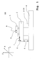
- FIG. 1 shows a vibration isolation system 100 based on pneumatic insulators 3.
- a mass to be isolated 2 is vibration-isolated by means of pneumatic insulators 3 or stored in isolation from a bottom 4.
- On the mass 2 itself is a movable table 1, in particular for the transport of wafers, lithography equipment, wafer handling systems and / or microscopes arranged.
- the system 100 includes four pneumatic isolators 3, a plurality of actuators, and a plurality of sensors 5, 6, 7, 8, and 9 as vibration transmitters. Via the sensors 6, 7, 8, and 9, vibrations or general movements of the base mass 2 and the load 1 to be isolated can be detected, converted into signals and forwarded to a control system, such as the first control system 10.
- the sensors 5, 6, 7, 8, and 9 as vibration signal generator thus provide the vibration representing sensor signals.
- the sensors are for example speed sensors, acceleration sensors and / or position sensors.
- the actuators are preferably actuators with a horizontal and / or vertical effective direction.
- the actuators are generally conventional force actuators. Examples of the force actuators or actuators are Lorentz motors and / or piezo actuators, etc.
- the actuators are generally in positioned close to the sensors. In one embodiment, an actuator is associated with each sensor.
- the pneumatic insulators 3 are, in particular in each case, equipped with a, preferably electronically, controllable valve 31.
- a pneumatic isolator 3 forms together with the valve 31 an actuator with a vertical effective direction.
- the horizontal direction or plane is defined by the axes X and Y and the vertical direction by the axis Z of the in FIG. 1 illustrated coordinate system illustrated.
- the axes X and Z are in the sheet plane and the axis Y perpendicular to the sheet.
- the sensors 5, 6, 7, 8, and 9 provide input signals, such as first and second sensor signals, to the control systems 10 and 20, in particular the control devices 12 and 22.
- the input signals may preferably be speed, acceleration and / or position signals.
- the sensor signals are charged in a special way to actuator control signals that the vibrations of a stored mass 2 are reduced or minimized, although moving tables 1 (so-called "stages" 1) move on it can.
- the control system makes special and general use of the pneumatic actuators 3, 31 as, preferably additional, force actuators. It is used in such a way that over-determination does not cause rule instability. Because With four control loops operating independently of each other on the valves 31, the system would become “rocking" due to the over-determination of the system.
- control of the pneumatic subsystem as a second control system 20 is restructured in order to avoid control instability and at the same time to achieve the best possible force effect.
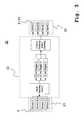
- FIG. 2 a first control system 10 with first sensors 11, a first control device 12 and first actuators 13 is illustrated.
- the sensors 1 to 6 are shown. These are assigned to the basic mass 2 and / or the table 1. They detect the vibrations of the base mass 2 and / or the table 1. Preferably, both the vibrations in the three degrees of freedom of the translation Xt, Yt and Zt and in the three degrees of freedom of the rotation Xt, Yr and Zr are detected.
- the first sensors 11 are generally mounted at different positions to detect the entire movement or all spatial direction.
- the first sensors 11 can be sensitive only in one degree of freedom or in several degrees of freedom. If sensors are only effective in one spatial direction, all spatial directions can be detected via a corresponding orientation of the sensors in the room and via a vectorial addition of the detected "forces".
- the processing or calculation takes place, for example, computer-based.
- the first control device 12 is designed to process the supplied first sensor signals into the first actuator control signals.
- the input steering matrix converts the first sensor signals into movement data, for example the base ground 2 and / or the table 1.
- the input steering matrix contains information or a working instruction as to how the individual first sensor signals must be processed together complete movement, in particular the base mass, or a disturbing vibration, preferably in all six degrees of freedom Xt, Yt, Zt and Xr, Yr and Zr to be able to determine.
- the specific components Xt, Yt and Zt as well as Xr, Yr and Zr of a vibration are respectively supplied to the controllers 1 to 6 here.
- corresponding compensation signals which can also be referred to as correction signals, are calculated.
- These compensation signals are preferably fed indirectly or via the output steering matrix described below to the first actuators 13 for counteracting the vibrations.
- engines 1 through 6 are shown. These are assigned to the basic mass 2 and / or the table 1.
- the vibrations, in particular the base mass 2 are reduced or compensated.
- both the oscillations in the three degrees of freedom of translation Xt, Yt and Zt and in the three degrees of freedom of rotation Xt, Yr and Zr are compensated.
- the actuators are generally mounted in different positions to compensate for the total mass movement or in all spatial directions.
- the actuators themselves can be effective only in one degree of freedom or in several degrees of freedom. If actuators are effective only in one spatial direction, all spatial directions can be detected via a corresponding orientation of the actuators in space and via a vectorial addition of the force action directions of the actuators.
- the effects or the countermovements of the individual actuators must be coordinated. Therefore, the first compensation signals are combined and shared, for example, depending on the position and / or the direction of action and / or other properties of the Actuators, processed and determines the actual first actuator control signals.
- the output steering matrix contains information or a work instruction in which way the individual first compensation signals of the degrees of freedom must be distributed to the individual actuators to complete movement or disturbing vibration, in particular the base mass 2, preferably in all six degrees of freedom Xt, Yt, Zt and Xr, Yr and Zr, to be able to compensate.
- the position and / or the direction of action of the first actuators 13 and / or further actuator properties are taken into account in the output steering matrix.
- the first control system 10 is for example based on at least one sensor-actuator combination selected from a group consisting of position sensor input to Lorentz motor output (so-called “proximity force loop”), geophone input to Lorentz motor output (so-called “velocity loop”), acceleration input to Lorentz motor output (so-called “acceleration loop”), stage position and acceleration input on Lorentz motor output (so-called “Stage Feedfoward”), bottom sensor to Lorentz motor output (so-called “ground feedforward”).
- the first control system 10 operates on the “logical axes" of the six degrees of freedom.
- the pneumatic isolators 3 in combination with other force actuators merely for the purpose of generating additional ones Compensation forces, where usually the combination of the same takes place on the actuator level.
- An example is the "mixing" of a Lorentz engine with a pneumatic insulator 3 and valve 31 as a control concept to a position actuator.
- the principle of the control according to the invention is based on operating the pneumatic system 20 analogously to the regulation of the first control system 10 and optional further control systems via an input steering matrix and an output steering matrix. These are also referred to as sensor input steering matrix or as actuator output steering matrix.
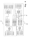
- FIG. 3 shows the pneumatic subsystem 20 with the Steeringmatrizen as the second control system 20.
- the second control system comprises second sensors 21, a second control device 22 and second actuators 23.
- the control principle is analogous to that in FIG. 2 illustrated control principle.
- the sensors 1 to 6 are replaced by the sensors A to D, which represent the position sensors 5 of the insulators 3.
- the motors 1 to 6 are replaced by the controllable valves 31 of the insulators 3, wherein in each case an insulator acts together with a valve 31 as a second actuator 23.
- a translational movement Zt corresponds to a movement along the axis Z, ie along the vertical. It represents a change in the height position of the base mass 2.
- a rotational movement Yr and / or Yr corresponds to a rotation about the axes X and / or Y, which together span the horizontal. It represents a kind of "tilting” or “twisting" of the base mass 2 in or out of the horizontal plane.
- the height control of the system according to the invention is no longer operated by means of position (height) sensor and associated isolator (so-called co-located control).
- a co-located control path exists when in each case a sensor and an actuator act as a controlled system and are arranged in spatial proximity to each other.
- the height control is performed by an input steering matrix, the position sensor data in the three degrees of freedom Zt, Xr and Yr converts and three independent control loop controls that output their output signals to the pneumatic actuator axes Zt, Xr and Yr.
- the setpoint of the controls in Xr and Yr is zero, for Zt just the height. Since "only" three control loops work on the system again, there is no overdetermination. Regulatory instability is not expected.
- the first control system 10 operates on the axes of the six degrees of freedom. That is, the first control system 10 is in both the three degrees of freedom of translation as well effective in the three degrees of freedom of rotation. A disturbing oscillation can therefore be counteracted in every degree of freedom of the movement. Ideally, the vibration is compensated. It is easily possible, the second control system 20, ie the effective as an actuator system pneumatic subsystem 20, participate in at least one of the three or three vertically effective degrees of freedom Zt, Xr and Yr as actuators or even act alone.
- a branch to the pneumatic subsystem 20 can be realized for each individual control system, as here for example the first control system 10.
- the output signals ie the actuator control signals of the control systems, the degrees of freedom Zt, Xr, Yr in, preferably adjustable, shares are divided.
- the output signals of the "traditional" actuator output steering matrix of the first control system 10 for example, for driving the Lorentz motors supplied.
- the output signals of the actuator output steering matrix of the pneumatic subsystem 20 are supplied. Examples of possible embodiments are described in the following FIGS. 4 and 5 shown.
- the first control system 10 and the second control system 20 and optional further control systems are coupled or merged together.
- FIG. 4 an exemplary coupling of the in FIG. 2 illustrated first control system 10 with the control in the pneumatic subsystem 20 as the second in FIG. 3 illustrated control system 20. All actuator control signals the degrees of freedom Xr, Yr and Zt are via the pneumatic, ie the pneumatic subsystem 20, unwound.
- the output signals from the controllers 3 to 5 of the first control system 10 are no longer supplied as first actuator control signals to the first actuators 13.
- the said output signals are supplied to the second pneumatic control system 20.
- the output signals of the controllers 3 to 5 are supplied to the output signals of the controllers A to C in the second pneumatic control system 20 or "added" to them.
- the means for merging 32 are embodied, for example, as a preferably digital interconnection and / or a computer routine.
- the merging takes place in dependence on the degree of freedom: For example, the output signal from the controller 3, which is the information in Zt is included, the output signal of the regulator A, which also includes the information in Zt supplied.
- the output signal from the controller 3 which is the information in Zt
- the output signal of the regulator A which also includes the information in Zt supplied.
- the merged output signals now contain the information in Xr, Yr, and Zt about the information detected by the second sensors 21, here the position sensors 5, here the positions of the base ground 2, as well as by the first sensors 11, here the acceleration and / or Velocity and / or position sensors, acquired information, here the vibrations of the basis mass 2 and / or the table 1.
- the merged output signals are fed to the "Output Steering Matrix". There, the actual second actuator control signals are generated or calculated.
- the respective second actuator actuating signals for the individual second pneumatic actuators 23, 3 and 31 (A to D) are calculated and then the second actuators A to D for vibration and / or position compensation in the degrees of freedom or axes Xr, Yr and Zt fed.
- the output signals of the controllers 1, 2 and 6 of the first control system 10 for Xt, Yt and Zr are supplied to the first actuators 13 via the output steering matrix.
- the actuator control signals of the degrees of freedom Xt, Yt and Zr are "unwound" via the first control system 10.
- the division is done according to the invention preferably in adjustable proportions.
- the division is not only in terms of amplitude.
- the division also takes place, alternatively or additionally, with regard to the frequencies of the actuator control signal.
- a high-pass / low-pass filter combination 33 is provided.
- low-frequency actuator control signals from the pneumatic subsystem 20 and higher frequency are processed by the "standard actuators" of the first control system 10. So will the limited Volume of the pneumatic control, which particularly preferably up to about 30Hz or preferably to about 10Hz or to about 5Hz can adequately control.
- FIG. 5 shows the exemplary coupling of the first control system 10 with the control in the pneumatic subsystem 20 as the second control system 20 by means of the high-pass / low-pass filter combination 33.
- the output signals of the controllers 3 to 5 are not supplied exclusively to the second control system 20. They are only partially supplied to the second control system 20.
- a high-pass (HP) and a low-pass filter (TP) 33 are provided in front of the merging means 32.
- the output signals of the controllers 3 to 5 are first supplied to the high-pass / low-pass filter combination 33. Output signals having a lower frequency are supplied to the second control system 20.
- the output signals of the first control system 10 are supplied as a first actuator control signals to a part of the first actuators 13 of the first control system 10.
- they are supplied to the second actuators 23 of the second control system 20 together with the output signals of the second control system 20 as second actuator control signals.
- Each control system within the control which requires force in one of the three vertically effective degrees of freedom, can thereby make full or partial use of the HP / TP combination 33 of the pneumatic subsystem 20.
- stage feedforward For an embodiment of the first control system 10, not shown in the figures, as a “stage feedforward”, it is also appropriate to carry out a separation according to input signals instead of a frequency separation.
- the conventional "stage feedforward" control relates to the "feedforward" control of movable tables 1, the so-called “Stages” 1 on the isolated mass 2.
- the acceleration signals and the position signals of the "stage” 1 thereby by a controller so calculated and given to the force actuators, for example Lorentz motors, that the effects of the force on the stored mass 2 is minimized.
- the pneumatics 3 and 31 could be realized as actuators for the position signals, while the Lorentz motors remain for the acceleration signals.
Abstract
Description
Die vorliegende Erfindung betrifft ein Verfahren zur Regelung eines aktiven Schwingungsisolationssystems und ein aktives Schwingungsisolationssystem, insbesondere zur schwingungsisolierten Lagerung von Lithographie-Geräten, Wafer-Handhabungssystemen und/oder Mikroskopen, wie zum Beispiel Rastermikroskopen.The present invention relates to a method for controlling an active vibration isolation system and an active vibration isolation system, in particular for the vibration-isolated storage of lithography equipment, wafer handling systems and / or microscopes, such as scanning microscopes.
Schwingungsisolationssysteme sind bekannt und werden in vielen Bereichen der Technik, wie zum Beispiel im Bereich der Halbleiterindustrie, benötigt. Beispielsweise zeigt die
Ein passives Schwingungsisolationssystem ist gekennzeichnet durch eine "einfache" Lagerung mit möglichst geringer mechanischer Steifigkeit, um die Übertragung von externen Schwingungen auf die zu isolierende Last zu reduzieren. Ein Luftlager und ein Polymer-Federelement zum Lagern sind zwei Beispiele für ein passives Schwingungsisolationssystem. Gegenüber einer passiven Schwingungsisolation, die durch eine Art Dämpfung der Schwingung oder eine Art "isolierte" Lagerung der Last gekennzeichnet ist, ist eine aktive Schwingungsisolation dadurch gekennzeichnet, dass die Schwingung aktiv kompensiert wird. Eine Bewegung, welche durch eine Schwingung induziert wird, wird durch eine entsprechende Gegenbewegung kompensiert. Zum Beispiel wird einer durch eine Schwingung induzierten Beschleunigung der Masse eine dem Betrag nach gleich große Beschleunigung, jedoch mit entgegengesetzten Vorzeichen entgegengesetzt. Die resultierende Gesamtbeschleunigung der Last ist gleich Null. Die Last verharrt in Ruhe bzw. der gewünschten Lage.A passive vibration isolation system is characterized by a "simple" bearing with the lowest possible mechanical stiffness, in order to reduce the transmission of external vibrations to the load to be isolated. An air bearing and a polymer spring element for bearing are two examples of a passive vibration isolation system. Compared to a passive vibration isolation, which is characterized by a kind of damping of the vibration or a kind of "isolated" bearing of the load, an active vibration isolation is characterized in that the vibration is actively compensated. A movement, which is induced by a vibration, is compensated by a corresponding counter-movement. For example, an acceleration of the mass induced by a vibration is opposed to an equal magnitude acceleration, but with opposite signs. The resulting total acceleration of the load is zero. The load remains at rest or the desired location.
Aktive Schwingungsisolationssysteme weisen daher, optional zusammen mit einer Lagerung mit möglichst mechanisch geringer Steifigkeit, zusätzlich ein Regelsystem auf, das eine Regeleinrichtung sowie Sensoren und Aktoren umfasst, mit denen gezielt von außen in das System eindringenden Schwingungen entgegengewirkt wird. Die Sensoren erfassen Bewegungen der zu lagernden Last. Über die Regeleinrichtung werden Kompensationssignale generiert, mit welchen die Aktoren angesteuert und so Kompensationsbewegungen generiert werden. Dabei gibt es die Möglichkeit, digitale oder analoge Regelungsstrecken zu verwenden oder aber auch beide zusammen, sogenannte hybride Regelungsstrecken.Active vibration isolation systems therefore have, optionally together with a bearing with as little mechanical rigidity as possible, in addition a control system, which includes a control device and sensors and actuators, with which targeted from the outside penetrating into the system vibrations is counteracted. The sensors detect movements of the load to be stored. Compensation signals are generated by means of the regulating device, with which the actuators are activated and thus compensation movements are generated. There is the possibility to use digital or analog control lines or even both together, so-called hybrid control lines.
Im Allgemeinen werden pro System und insbesondere pro zu lagernde Basismasse bis zu vier Luftlager, welche auch als pneumatische Isolatoren oder Schwingungsisolatoren bezeichnet werden, eingesetzt. Jeder der Isolatoren wird jeweils "alleine" nur zur Höhenregelung eingesetzt. Daher werden wegen der Überbestimmtheit nur drei davon mit einem, insbesondere steuerbaren, Ventil ausgerüstet. Denn eine Ebene, hier die horizontale Ebene, ist bereits eindeutig durch drei Auflagepunkte definiert. Der vierte Isolator wird passiv von einem der drei anderen Ventile mitversorgt (sogenannte "master-slave-Konfiguration"). Damit werden dann nur jeweils drei der vier Isolatoren wirklich mittels einer Regelung erfasst, der vierte bleibt passiv.In general, up to four air bearings, which are also referred to as pneumatic isolators or vibration isolators, are used per system and in particular per base mass to be stored. Each of the isolators is used "alone" only for height control. Therefore, because of over-determination, only three of them become one, In particular controllable, valve equipped. For a plane, here the horizontal plane, is already clearly defined by three points of support. The fourth isolator is passively fed by one of the three other valves (so-called "master-slave configuration"). Thus only three of the four insulators are then really detected by means of a regulation, the fourth remains passive.
Die Anforderungen an Schwingungsisolationssysteme nehmen, insbesondere in der Halbleiterindustrie, immer weiter zu. Beispielsweise werden auf der Basismasse verfahrbare oder beweglich angeordnete Tische, sogenannte "stages", zum Transport von Wafern, verwendet. Diese erzeugen durch ihre Bewegung auf der Basismasse Schwingungen in dem System selbst, sogenannte "intrinsische" Schwingungen. Daher ist es erforderlich, die durch die Bewegung einer "Stage" erzeugten Schwingungen effektiv zu kompensieren. Es werden hohe Anforderungen an ein System zur Schwingungsisolation oder Schwingungskompensation gestellt, da die "Stages" zum Teil ein recht großes Gewicht besitzen. Insbesondere das "dauerhafte" Bereitstellen der erforderlichen Kraft durch die verwendeten Aktoren erweist sich als problematisch.The demands on vibration isolation systems are increasing, especially in the semiconductor industry. For example, movable or movably arranged tables, so-called "stages", for transporting wafers are used on the base mass. As a result of their movement on the base mass, these generate vibrations in the system itself, so-called "intrinsic" oscillations. Therefore, it is necessary to effectively compensate for the vibrations generated by the movement of a "Stage". There are high demands on a system for vibration isolation or vibration compensation, since the "Stages" sometimes have a fairly large weight. In particular, the "permanent" provision of the required force by the actuators used proves to be problematic.
Vor diesem Hintergrund hat sich die vorliegende Erfindung zur Aufgabe gestellt, eine System und ein Verfahren zur aktiven Schwingungsisolation bereitzustellen, welche die vorstehend beschriebenen Nachteile des Standes der Technik zumindest vermindern.Against this background, the present invention has the object to provide a system and a method for active vibration isolation, which at least reduce the disadvantages of the prior art described above.
Dabei soll es insbesondere möglich sein, die Erfindung in bereits bestehende Regelungskonzepte integrieren zu können bzw. die bekannten Regelungskonzepte erweitern zu können.It should be possible in particular to be able to integrate the invention into existing control concepts or to be able to expand the known control concepts.
Gelöst werden die genannten Aufgaben durch ein aktives Schwingungsisolationssystem und ein Verfahren zur Regelung eines aktiven Schwingungsisolationssystems gemäß den unabhängigen Ansprüchen.The above objects are achieved by an active vibration isolation system and a method for controlling an active vibration isolation system according to the independent claims.
Vorteilhafte Ausführungsformen sind Gegenstand der jeweiligen Unteransprüche.Advantageous embodiments are the subject of the respective subclaims.
Zunächst beansprucht die vorliegende Anmeldung ein aktives Schwingungsisolationssystem umfassend
- a) eine Basismasse zum Lagern einer zu isolierenden Last,
- b) insbesondere pneumatische, Schwingungsisolatoren mit, vorzugsweise regelbaren, Ventilen zum Stützen der Basismasse gegenüber einer Unterlage,
- c) Positionssensoren zum Liefern von, vorzugsweise vertikalen, Positionssignalen der Basismasse,
- d) ein erstes Regelsystem zur Schwingungskompensation in zumindest einem Freiheitsgrad der Translation Xt, Yt und/oder Zt und zumindest einem Freiheitsgrad der Rotation Xr, Yr und/oder Zr mit wenigstens
- d1) ersten Sensoren zum Liefern von Schwingungen repräsentierenden ersten Sensorsignalen,
- d2) ersten Aktoren zur Schwingungskompensation, die durch Zuführen von ersten Aktor-Stellsignalen ansteuerbar sind, und
- d3) einer ersten Regeleinrichtung, welche zum Verarbeiten der gelieferten ersten Sensorsignale in die ersten Aktor-Stellsignale ausgebildet ist, und
- e) ein zweites, vorzugsweise pneumatisches, Regelsystem zur Schwingungskompensation in wenigstens einem von drei vertikal wirksamen Freiheitsgraden Zt, Xr und/oder Yr zumindest aus
- e1) den Positionssensoren als zweite Sensoren zum Liefern von Schwingungen repräsentierenden zweiten Sensorsignalen,
- e2) den, insbesondere pneumatischen, Schwingungsisolatoren, vorzugsweise mit den Ventilen, als zweite Aktoren zur Schwingungskompensation, die durch Zuführen von zweiten Aktor-Stellsignalen ansteuerbar sind und
- e3) einer zweiten Regeleinrichtung, welche zum Verarbeiten der gelieferten Positionssignale in die zweiten Aktor-Stellsignale ausgebildet ist.
- a) a base mass for supporting a load to be insulated,
- b) in particular pneumatic, vibration isolators with, preferably controllable, valves for supporting the base mass relative to a base,
- c) position sensors for supplying, preferably vertical, position signals of the base mass,
- d) a first control system for vibration compensation in at least one degree of freedom of translation Xt, Yt and / or Zt and at least one degree of freedom of rotation Xr, Yr and / or Zr with at least
- d1) first sensors for supplying vibrations to first sensor signals,
- d2) first actuators for vibration compensation, which can be controlled by supplying first actuator actuating signals, and
- d3) a first control device, which is designed to process the supplied first sensor signals into the first actuator control signals, and
- e) a second, preferably pneumatic, control system for vibration compensation in at least one of three vertically effective degrees of freedom Zt, Xr and / or Yr at least
- e1) the position sensors as second sensors for providing second sensor signals representing vibrations,
- e2) the, in particular pneumatic, vibration isolators, preferably with the valves, as second actuators for vibration compensation, which can be controlled by supplying second actuator control signals and
- e3) a second control device, which is designed to process the delivered position signals in the second actuator control signals.
Im Allgemeinen ist das erste Regelsystem mit dem zweiten Regelsystem gekoppelt. In einer ersten Ausführungsform sind Mittel zum Zusammenführen der ersten Aktor-Stellsignale, die in wenigstens einer der drei vertikalen Freiheitsgrade Zt, Xr und/oder Yr wirksam sind, mit den in dem entsprechenden Freiheitsgrad wirksamen zweiten Aktor-Stellsignalen vorgesehen. Die Mittel zum Zusammenführen sind in einer bevorzugten Ausgestaltung der Erfindung als eine Schaltung ausgeführt. Diese kann als eine analoge und/oder eine digitale Schaltung ausgeführt sein.In general, the first control system is coupled to the second control system. In a first embodiment, means for merging the first actuator actuating signals, which are effective in at least one of the three vertical degrees of freedom Zt, Xr and / or Yr, are provided with the second actuator actuating signals effective in the corresponding degree of freedom. The means for merging are executed in a preferred embodiment of the invention as a circuit. This can be designed as an analog and / or a digital circuit.
Weiterhin liegt im Rahmen der Erfindung auch ein Verfahren zur Regelung eines mit einer Basismasse zur Lagerung einer zu isolierenden Last ausgestatteten aktiven Schwingungsisolationssystems. Das Verfahren umfasst die folgenden Verfahrensschritte:
- Erfassen von Schwingungen zumindest der Basismasse und/oder einer zu isolierenden Last mittels einer Vielzahl von ersten Sensoren,
- Erfassen von, insbesondere vertikalen, Positionen der Basismasse mittels einer Vielzahl von Positionssensoren als zweite Sensoren,
- Bereitstellen von ersten Sensorsignalen, welche die erfassten Schwingungen repräsentieren, und von zweiten Sensorsignalen, welche die erfassten, insbesondere vertikalen, Positionen repräsentieren,
- Verarbeiten der bereitgestellten ersten und zweiten Sensorsignale zu ersten Aktor-Stellsignalen zum Ansteuern von ersten Aktoren und zu zweiten Aktor-Stellsignalen zum Ansteuern von zweiten Aktoren, welche als, vorzugsweise pneumatische, Schwingungsisolatoren zum Stützen der Basismasse gegenüber einer Unterlage bereitgestellt werden,
- Zuführen der ersten und zweiten Aktor-Stellsignale zu den ersten und zweiten Aktoren zum Entgegenwirken der Schwingungen.
- Detecting vibrations of at least the base mass and / or a load to be isolated by means of a plurality of first sensors,
- Detecting, in particular vertical, positions of the base ground by means of a plurality of position sensors as second sensors,
- Providing first sensor signals representing the detected vibrations and second sensor signals representing the detected, in particular vertical, positions
- Processing the provided first and second sensor signals to first actuator actuating signals for actuating first actuators and to second actuator actuating signals for actuating second actuators, which are provided as, preferably pneumatic, vibration isolators for supporting the base mass with respect to a base,
- Supplying the first and second actuator actuating signals to the first and second actuators to counteract the vibrations.
Das erfindungsgemäße Verfahren ist insbesondere ausführbar mittels des erfindungsgemäßen Systems. Das erfindungsgemäße System ist insbesondere ausgebildet zur Ausführung des erfindungsgemäßen Verfahrens.The process according to the invention can be carried out in particular by means of the system according to the invention. The system according to the invention is in particular designed for carrying out the method according to the invention.
Unter einer Schwingungskompensation wird verstanden, dass den störenden Bewegungen oder Schwingungen, die au das System einwirken, entgegengewirkt werden soll. Im Idealfall wird die Bewegung oder die Schwingung kompensiert. Dies erfolgt vorzugsweise in allen sechs Freiheitsgraden der Bewegung.A vibration compensation is understood to be counteracted by the disturbing movements or vibrations which act on the system. Ideally, the motion or vibration is compensated. This is preferably done in all six degrees of freedom of movement.
Die sechs Freiheitsgrade sind die drei Freiheitsgraden der Translation Xt, Yt und Zt und die drei Freiheitsgrade der Rotation Xr, Yr und Zr. Die Koordinaten X und Y definieren hierbei die horizontale Ebene und die Koordinate Z die Vertikale dazu. Im Allgemeinen wird die horizontale Ebene durch die Basismasse definiert.The six degrees of freedom are the three degrees of freedom of translation Xt, Yt and Zt and the three degrees of freedom of rotation Xr, Yr and Zr. The coordinates X and Y define the horizontal plane and the coordinate Z the vertical. In general, the horizontal plane is defined by the base ground.
Die vorstehend genannten vertikal wirksamen Freiheitsgrade sind
- der Freiheitsgrad der Translation in vertikaler Richtung Zt, beispielsweise zum Festlegen einer Höhenveränderung der Basismasse,
- der Freiheitsgrad der Rotation in horizontaler Richtung Xr, beispielsweise zum Festlegen einer Kippbewegung der Basismasse in der horizontalen Ebene und
- der Freiheitsgrad der Rotation in horizontaler Richtung Yr, beispielsweise zum Festlegen einer Kippbewegung der Basismasse in der horizontalen Ebene senkrecht zu Xr.
- the degree of freedom of translation in the vertical direction Zt, for example for determining a change in the height of the base mass,
- the degree of freedom of rotation in the horizontal direction Xr, for example, for determining a tilting movement of the base mass in the horizontal plane and
- the degree of freedom of rotation in the horizontal direction Yr, for example, for fixing a tilting movement of the base ground in the horizontal plane perpendicular to Xr.
Sofern dies nicht explizit ausgeführt sein sollte, beziehen sich die nachfolgenden Beschreibungen sowohl auf das erste als auch auf das zweite Regelsystem, den ersten und den zweiten Sensor, den ersten und den zweiten Aktor, ....Unless explicitly stated, the following descriptions refer to both the first and second control systems, the first and second sensors, the first and second actuators, ....
Die Sensoren erfassen, mittelbar und/oder unmittelbar, eine Massenbewegungen der Basismasse und/oder der Last. Diese Massenbewegung ist dabei vorzugsweise eine Schwingung. Die Massenbewegung ist über eine Beschleunigung, eine Geschwindigkeit und/oder eine Positionsveränderung der Basismasse und/oder der Last charakterisiert. Zum Beispiel ist die Position der Basismasse abhängig von den auf sie einwirkenden Schwingungen.The sensors detect, indirectly and / or directly, a mass movement of the base mass and / or the load. This mass movement is preferably a vibration. The mass movement is characterized by an acceleration, a velocity and / or a positional change of the base mass and / or the load. For example, the position of the base mass is dependent on the vibrations acting on it.
Der Sensor kann ein Sensor sein, der geeignet ist, nur die Schwingungen oder eine Störgröße in einem Freiheitsgrad zu erfassen. Der Sensor kann aber auch ein Sensor sein, der geeignet ist, die Schwingungen oder eine Störgröße in einer Vielzahl von Freiheitsgraden zu erfassen. Beispiele für die Sensoren sind Geophonsensoren und/oder piezo-elektrische Sensoren. Die Aufzählung ist jedoch nur beispielhaft und nicht abschließend.The sensor may be a sensor capable of detecting only the vibrations or a disturbance in one degree of freedom. The sensor can also be a sensor which is suitable for detecting the vibrations or a disturbance variable in a plurality of degrees of freedom. Examples of the sensors are geophone sensors and / or piezoelectric sensors. However, the list is only an example and not exhaustive.
Die Positionssensoren, insbesondere zum Liefern der vertikalen Positionssignale, liefern eine Information über eine Position und/oder eine Positionsänderung, vorzugsweise der Basismasse. Das kann unmittelbar oder mittelbar erfolgen. Bevorzugt wird hierbei die Position, wie zum Beispiel die Höhe, als solches und somit unmittelbar geliefert. Die Positionssensoren, insbesondere zum Liefern der vertikalen Positionssignale, können auch noch weitere Funktionen aufweisen. Sie können zusätzlich auch noch die Beschleunigung und/oder die Geschwindigkeit erfassen.The position sensors, in particular for providing the vertical position signals, provide information about a position and / or a position change, preferably the base mass. This can be done directly or indirectly. Preferably, the position, such as the height, is delivered as such and thus directly. The position sensors, in particular for providing the vertical position signals, may also have further functions. You can also record the acceleration and / or the speed.
Die Sensorsignale können analoge und/oder digitale Signale sein. Ein Sensorsignal kann ein Signal sein, welches nur die Schwingungen oder eine Störgröße in einem Freiheitsgrad erfasst. Das Sensorsignal kann aber auch ein Signal sein, das die Schwingungen oder eine Störgröße in einer Vielzahl von Freiheitsgraden erfasst.The sensor signals may be analog and / or digital signals. A sensor signal may be a signal which detects only the vibrations or a disturbance variable in one degree of freedom. The sensor signal may also be a signal that detects the vibrations or a disturbance variable in a plurality of degrees of freedom.
Die Aktor-Stellsignale können analoge und/oder digitale Signale sein. Ein Aktor-Stellsignal stellt eine Art Kompensationssignal dar. Eine Schwingung einer zu lagernden Last wird aktiv kompensiert. Die Aktoren können in einem Freiheitsgrad oder in einer Mehrzahl von Freiheitsgraden der Bewegung wirksam sein. Ein Aktor-Stellsignal kann daher ein Signal sein, das Informationen für nur einen Freiheitsgrad beinhaltet. Es kann aber auch ein Signal sein, das Informationen für eine Vielzahl von Freiheitsgraden beinhaltet. Beispiele für die Aktoren umfassen Lorentzmotoren, wie zum Beispiel Tauchspulen, und/oder piezo-elektrische Aktoren. Die Aufzählung ist jedoch nur beispielhaft und nicht abschließend.The actuator control signals can be analog and / or digital signals. An actuator control signal represents a kind of compensation signal. An oscillation of a load to be stored is actively compensated. The actuators can work in one Degree of freedom or be effective in a plurality of degrees of freedom of movement. An actuator control signal may therefore be a signal containing information for only one degree of freedom. But it can also be a signal that contains information for a variety of degrees of freedom. Examples of the actuators include Lorentz motors, such as plunger coils, and / or piezoelectric actuators. However, the list is only an example and not exhaustive.
Die Aktoren weisen einen Wirkungsbereich auf. Der jeweilige Wirkungsbereich ist definiert zum Beispiel durch die Größe, die Richtung und/oder die Frequenz des Aktor-Stellsignals. Die pneumatischen Schwingungsisolatoren als zweite Aktoren besitzen eine Kraftwirkung in den drei vertikal wirksamen Freiheitsgraden Zt, Xr und Yr.The actuators have an effective range. The respective effective range is defined, for example, by the size, the direction and / or the frequency of the actuator actuating signal. The pneumatic vibration isolators as second actuators have a force effect in the three vertically effective degrees of freedom Zt, Xr and Yr.
Ebenso kann die Regeleinrichtung eine digital und/oder eine analog arbeitende Regeleinrichtung sein.Likewise, the control device may be a digitally and / or analogously operating control device.
In einer Ausgestaltung der Erfindung wird ein erstes bzw. das erste Regelsystem zur Schwingungskompensation in zumindest einem Freiheitsgrad der Translation Xt, Yt und/oder Zt und/oder in zumindest einem Freiheitsgrad der Rotation Xr, Yr und/oder Zr bereitgestellt. D.h. das erste Regelsystem ist in den genannten Freiheitsgraden wirksam. Vorzugsweise ist das erste Regelsystem in allen drei Freiheitsgrade der Translation Xt, Yt und Zt und in allen drei Freiheitsgraden der Rotation Xr, Yr und Zr wirksam.In one embodiment of the invention, a first or the first control system is provided for vibration compensation in at least one degree of freedom of translation Xt, Yt and / or Zt and / or in at least one degree of freedom of rotation Xr, Yr and / or Zr. That the first control system is effective in the stated degrees of freedom. Preferably, the first control system operates in all three degrees of freedom of translation Xt, Yt and Zt and in all three degrees of freedom of rotation Xr, Yr and Zr.
In einer Ausgestaltung wird das erste Regelsystem zumindest durch die ersten Sensoren, die ersten Aktoren und eine erste Regeleinrichtung, welche zum Verarbeiten der ersten Sensorsignale in die ersten Aktor-Stellsignale ausgebildet ist, bereitgestellt. Die ersten Sensoren sind ausgebildet zur Erfassung von Schwingungen in zumindest einem Freiheitsgrad der Translation Xt, Yt und/oder Zt und/oder in zumindest einem Freiheitsgrad der Rotation Xr, Yr und/oder Zr. Vorzugsweise sind die ersten Sensoren in allen drei Freiheitsgrade der Translation Xt, Yt und Zt und in allen drei Freiheitsgraden der Rotation Xr, Yr und Zr wirksam. Die ersten Aktoren zur Schwingungskompensation sind in zumindest einem Freiheitsgrad der Translation Xt, Yt und/oder Zt und/oder in zumindest einem Freiheitsgrad der Rotation Xr, Yr und/oder Zr wirksam. Vorzugsweise sind die ersten Aktoren in allen drei Freiheitsgrade der Translation Xt, Yt und Zt und in allen drei Freiheitsgraden der Rotation Xr, Yr und Zr wirksam.In one embodiment, the first control system is at least by the first sensors, the first actuators and a first control device, which is designed for processing the first sensor signals in the first actuator actuating signals provided. The first sensors are designed to detect vibrations in at least one degree of freedom of translation Xt, Yt and / or Zt and / or in at least one degree of freedom of rotation Xr, Yr and / or Zr. Preferably, the first sensors operate in all three degrees of freedom of translation Xt, Yt and Zt and in all three degrees of freedom of rotation Xr, Yr and Zr. The first actuators for vibration compensation are effective in at least one degree of freedom of translation Xt, Yt and / or Zt and / or in at least one degree of freedom of rotation Xr, Yr and / or Zr. Preferably, the first actuators operate in all three degrees of freedom of translation Xt, Yt and Zt and in all three degrees of freedom of rotation Xr, Yr and Zr.
In einer weiteren Ausführung der Erfindung wird ein zweites bzw. das zweite Regelsystem zur Schwingungskompensation in zumindest einem von drei vertikal wirksamen Freiheitsgraden Zt, Xr und/oder Yr bereitgestellt. Das zweite Regelsystem ist in den genannten Freiheitsgraden wirksam. Vorzugsweise ist das zweite Regelsystem in allen drei vertikal wirksamen Freiheitsgraden Zt, Xr und Yr wirksam.In a further embodiment of the invention, a second or the second control system for vibration compensation is provided in at least one of three vertically effective degrees of freedom Zt, Xr and / or Yr. The second control system is effective in the stated degrees of freedom. Preferably, the second control system operates in all three vertically effective degrees of freedom Zt, Xr and Yr.
In einer bevorzugten Ausführungsform wird das zweite Regelsystem zumindest durch die zweiten Sensoren, die zweiten Aktoren und eine zweite Regeleinrichtung, welche zum Verarbeiten der zweiten Sensorsignale in die zweiten Aktor-Stellsignale ausgebildet ist, bereitgestellt. Da die zweiten Aktoren insbesondere durch die vorstehend genannten pneumatischen Schwingungsisolatoren bereitgestellt werden, wird das zweite Regelsystem nachfolgend auch als pneumatisches System oder Subsystem bezeichnet.In a preferred embodiment, the second control system is provided at least by the second sensors, the second actuators and a second control device, which is designed to process the second sensor signals into the second actuator control signals. In particular, since the second actuators are provided by the above-mentioned pneumatic vibration isolators, The second control system is also referred to below as a pneumatic system or subsystem.
Das erste Regelsystem und das zweite Regelsystem können auch in einem einzigen Regelsystem bereitgestellt werden. In diesem einen Regelsystem können das erste und das zweite Regelsystem beispielsweise durch entsprechende Routinen zur Datenverarbeitung und/oder durch entsprechende Schaltungen bereitgestellt werden.The first control system and the second control system can also be provided in a single control system. In this one control system, the first and the second control system can be provided for example by corresponding routines for data processing and / or by corresponding circuits.
Vorzugsweise erfolgt die Schwingungskompensation in dem zumindest einen vertikal wirksamen Freiheitsgrad der Translation Zt und den zumindest zwei vertikal wirksamen Freiheitsgraden der Rotation Xr und Yr durch das erste Regelsystem und/oder das zweite Regelsystem.Preferably, the vibration compensation takes place in the at least one vertically effective degree of freedom of translation Zt and the at least two vertically effective degrees of freedom of rotation Xr and Yr by the first control system and / or the second control system.
In einer Ausführungsform wird wenigstens von dem ersten Regelsystem eine Abzweigung zu dem zweiten Regelsystem bereitgestellt.In one embodiment, a branch to the second control system is provided at least by the first control system.
Die Abzweigung oder ein Zusammenführen des ersten und des zweiten Regelsystems ist derart, dass das erste und das zweite Regelsystem derart gekoppelt sind, dass diese in zumindest einem Freiheitsgrad zusammenwirken.The branching or merging of the first and the second control system is such that the first and the second control system are coupled in such a way that they interact in at least one degree of freedom.
Insbesondere macht das erste Regelsystem dabei von einer Kraftwirkung in wenigstens einer der drei vertikal wirksamen Freiheitsgrade Xr, Yr und/oder Zt komplett oder anteilig Gebrauch.In particular, the first control system makes full or proportionate use of a force effect in at least one of the three vertically effective degrees of freedom Xr, Yr and / or Zt.
In einer erfindungsgemäßen Variante werden die ersten und die zweiten Aktor-Stellsignale zur Schwingungskompensation in dem zumindest einem Freiheitsgrad der Translation Zt und den zumindest zwei Freiheitsgraden der Rotation Xr und Yr nach Anteilen aufgeteilt. Vorzugsweise erfolgt hierbei das Aufteilen nach einstellbaren Anteilen.In a variant according to the invention, the first and second actuator control signals are used for vibration compensation in the at least one degree of freedom of the translation Zt and the at least two degrees of freedom of the rotation Xr and Yr divided into shares. Preferably, this is done by dividing into adjustable proportions.
Weiterhin ist die Erfindung in einer Ausgestaltung dadurch gekennzeichnet, dass die ersten und/oder die zweiten Aktor-Stellsignale, die in dem Freiheitsgrad der vertikalen Translation Zt und/oder den zwei Freiheitsgraden der vertikalen Rotation Xr und Yr, wirksam sind, in Abhängigkeit von einer Amplitude und/oder in Abhängigkeit von einer Frequenz der entgegenzuwirkenden Schwingungen nach Anteilen aufgeteilt wird bzw. werden. Beispielsweise werden bei Schwingungen mit großen Amplituden, die einen entsprechend großen Hub zur Kompensation erfordern, die zweite Aktoren, hier im Wesentlichen die pneumatischen Schwingungsisolatoren, eingesetzt.Furthermore, in one embodiment, the invention is characterized in that the first and / or the second actuator actuating signals, which are effective in the degree of freedom of the vertical translation Zt and / or the two degrees of freedom of the vertical rotation Xr and Yr, depending on a Amplitude and / or divided into proportions depending on a frequency of the counteracting oscillations or shares. For example, in oscillations with large amplitudes, which require a correspondingly large stroke for compensation, the second actuators, in this case essentially the pneumatic vibration isolators, are used.
In einer Variante der Erfindung wird den zweiten Aktor-Stellsignalen ein gegenüber den ersten Aktor-Stellsignalen tieffrequenter Bereich zur Schwingungskompensation zugeordnet wird. Vorzugsweise werden die zweiten Aktor-Stellsignale in einem Frequenzbereich von bis zu etwa 30 Hz, bevorzugt von bis zu etwa 10 Hz, besonders bevorzugt von bis zu etwa 5 Hz, zur Schwingungskompensation bereitgestellt. Dazu ist insbesondere eine Hochpass-/Tiefpass-Filterkombination zwischen dem ersten Regelsystem und dem zweiten Regelsystem angeordnet oder geschaltet, so dass den zweiten Aktor-Stellsignalen die ersten Aktor-Stellsignale zugeführt werden, die in dem tieffrequenten Bereich liegen.In a variant of the invention, the second actuator actuating signals are assigned a low-frequency range for vibration compensation in relation to the first actuator actuating signals. The second actuator actuating signals are preferably provided in a frequency range of up to about 30 Hz, preferably of up to about 10 Hz, particularly preferably of up to about 5 Hz, for vibration compensation. For this purpose, in particular a high-pass / low-pass filter combination between the first control system and the second control system is arranged or connected so that the second actuator control signals are supplied to the first actuator control signals, which are in the low-frequency range.
Jedes Regelungssystem innerhalb der Regelung, welches eine Kraftwirkung in wenigstens einem der drei vertikal wirksamen Freiheitsgrade benötigt, kann komplett oder anteilig, insbesondere über eine HP/TP-Kombination, vom pneumatischen Subsystem Gebrauch machen.Each control system within the control system, which requires a force effect in at least one of the three vertically effective degrees of freedom, can make use of the pneumatic subsystem completely or proportionally, in particular via an HP / TP combination.
In einer Ausgestaltung der Erfindung werden die ersten Sensorsignale, vorzugsweise ausschließlich, zu den ersten Aktor-Stellsignalen verarbeitet und/oder die ersten Aktor-Stellsignale, vorzugsweise ausschließlich, den ersten Aktoren zugeführt.In one embodiment of the invention, the first sensor signals, preferably exclusively, are processed to the first actuator actuating signals and / or the first actuator actuating signals, preferably exclusively, supplied to the first actuators.
In einer alternativen oder ergänzenden Ausgestaltung werden die zweiten Sensorsignale, vorzugsweise ausschließlich, zu den zweiten Aktor-Stellsignalen verarbeitet und/oder die zweiten Aktor-Stellsignale, vorzugsweise ausschließlich, den zweiten Aktoren zugeführt.In an alternative or additional embodiment, the second sensor signals, preferably exclusively, are processed to the second actuator actuating signals and / or the second actuator actuating signals, preferably exclusively, are supplied to the second actuators.
In einer bevorzugten Ausgestaltung werden die ersten Sensoren als Beschleunigungssensoren und/oder die ersten Aktoren als Lorentzmotoren bereitgestellt.In a preferred embodiment, the first sensors are provided as acceleration sensors and / or the first actuators as Lorentz motors.
In einer Weiterbildung der Erfindung werden die ersten Aktor-Stellsignale, welche in wenigstens einem der drei vertikalen Freiheitsgrade Zt, Xr und/oder Yr wirksam sind, mit den in dem entsprechenden Freiheitsgrad wirksamen zweiten Aktor-Stellsignalen zusammengeführt. Beispielsweise wird das erste Aktor-Stellsignal, das in dem Freiheitsgrad Zt wirksam ist, mit dem zweiten Aktor-Stellsignale, das ebenso in dem Freiheitsgrade Zt wirksam ist, zusammengeführt.In a development of the invention, the first actuator actuating signals, which are effective in at least one of the three vertical degrees of freedom Zt, Xr and / or Yr, are combined with the second actuator actuating signals which are effective in the corresponding degree of freedom. For example, the first actuator actuating signal, which is effective in the degree of freedom Zt, is merged with the second actuator actuating signal, which is also effective in the degree of freedom Zt.
Eine weitere Ausführungsform der Erfindung ist dadurch gekennzeichnet, dass die ersten Aktor-Stellsignale frequenzabhängig gefiltert werden und gefilterte erste Aktor-Stellsignale in einem tieffrequenten Bereich den zweiten Aktoren und gefilterte erste Aktor-Stellsignale in einem höherfrequenter Teil den ersten Aktoren zugeführt werden.A further embodiment of the invention is characterized in that the first actuator control signals are filtered frequency-dependent and filtered first actuator control signals in a low-frequency range the second actuators and filtered first actuator control signals are supplied in a higher-frequency part of the first actuators.
Allgemeinem wird die Erfindung beschrieben durch ein Schwingungsisolationssystem mit pneumatischen Isolatoren, die nicht nur zur Positionslagerung sondern auch zur Schwingungs- oder Kraftkompensation verwendet werden. Durch die Verwendung des pneumatischen Systems als ein zusätzliches Kraftaktor-System lassen sich höhere Kräfte zur Kompensation erzeugen. Zudem kann die Abwärme, zum Beispiel durch hohe Ströme der Lorentzmotoren, die oft als erste Aktoren eingesetzt werden, reduziert oder minimiert werden.In general, the invention is described by a vibration isolation system with pneumatic isolators, which are used not only for positional storage but also for vibration or force compensation. By using the pneumatic system as an additional force actuator system, higher forces can be generated for compensation. In addition, the waste heat, for example due to high currents of the Lorentz motors, which are often used as first actuators, can be reduced or minimized.
Ein der Erfindung zugrunde liegendes Prinzip der Regelung basiert darauf, das pneumatische System, insbesondere analog zur Regelung der restlichen Regelungssysteme, wie des ersten Regelsystems, über eine "Sensor-Input-Steering-Matrix" und/oder eine "Aktor-Output-Steering-Matrix" zu betreiben, welche Sensor-Einzelsignale bzw. Aktor-Einzelsignale in Freiheitsgrade umrechnet bzw. umrechnen.A control principle on which the invention is based is based on the pneumatic system, in particular analogously to the regulation of the remaining control systems, such as the first control system, via a "sensor input steering matrix" and / or an "actuator output steering system". Matrix "to operate, which converts individual sensor signals or actuator individual signals in degrees of freedom or convert.
Dies ermöglicht, in einem Schwingungsisolationssystem alle aktiv geregelten pneumatischen Isolatoren einzusetzen. In einer bevorzugten Ausgestaltung der Erfindung werden vier, wie statt wie bisher nur drei, aktiv geregelte oder regelbare pneumatische Isolatoren innerhalb des Systems eingesetzt.This makes it possible to use all actively controlled pneumatic isolators in a vibration isolation system. In a preferred embodiment of the invention, four, as instead of as previously only three, actively regulated or adjustable pneumatic isolators used within the system.
Vorzugsweise werden alle Isolatoren des Systems, die insbesondere alle jeweils ein steuerbares Ventilsystem umfassen, in der Regelung verwendet. Beispielsweise kommen bei einem System mit vier Isolatoren nicht nur drei steuerbare Ventile sondern vier steuerbare Ventile zum Einsatz, ohne dass es durch eine Überbestimmtheit zu Problemen in der Regelung kommt.Preferably, all isolators of the system, which in particular each comprise in each case a controllable valve system, are used in the control. For example, in a system with four isolators not only three controllable valves but four controllable valves are used, without over-determining problems in the control.
In einer konkreten Ausgestaltung der Erfindung ist ein Schwingungsisolationssystem vorgesehen, bei dem das pneumatische Subsystem aus vier Isolatoren mit jeweils dazugehörigen aktiv regelbaren Ventilen gebildet wird. Das pneumatische Subsystem wird in den Freiheitsgraden, in denen es wirksam ist, angesprochen und geregelt. Dabei kann die Regelung vom Kraftwirkungspotenzial der pneumatischen Isolatoren Gebrauch machen, indem über erfindungsgemäße Verschaltungen und/oder Routinen die unterschiedlichen Regelungssubsysteme, wie zum Beispiel das erste Regelsystem, ihre Stellsignale zumindest teilweise auch auf das pneumatische Subsystem, hier zum Beispiel ausgeführt als das zweite Regelsystem, leiten. Dabei kann in einer Variante der Erfindung sogar jedes Regelungssystem innerhalb der Regelung, welches eine Kraftwirkung in einer der drei vertikal wirksamen Freiheitsgrade benötigt, komplett oder anteilig, insbesondere auch über eine Hochpass/Tiefpass-Kombination (HP/TP-Kombination), vom pneumatischen Subsystem Gebrauch machen.In a specific embodiment of the invention, a vibration isolation system is provided, in which the pneumatic subsystem is formed of four insulators, each associated with actively controllable valves. The pneumatic subsystem is addressed and regulated in the degrees of freedom in which it is effective. In this case, the control can make use of the force effect potential of the pneumatic isolators by means of interconnections and / or routines according to the invention, the different control subsystems, such as the first control system, their control signals at least partially on the pneumatic subsystem, here for example as the second control system, conduct. In this case, in a variant of the invention, even any control system within the control, which requires a force in one of the three vertically effective degrees of freedom, completely or proportionally, in particular via a high-pass / low-pass combination (HP / TP combination), from the pneumatic subsystem Make use.
Jede Art der Regelung ist darauf angewiesen, Informationen oder Daten zu erhalten, die es erlauben, die Bewegung einer zu isolierenden Anordnung zu erfassen und durch ein Berechnen und/oder Bereitstellen einer Art Gegenbewegung, die Anordnung in einem Ruhezustand zu belassen oder in einen bewegungs- oder schwingungsarmen Zustand zurückzuversetzen.Each type of control relies upon obtaining information or data that allows the movement of an assembly to be isolated to be detected and left in a quiescent state by calculating and / or providing some countermovement, or moving it into a motionless state. or return to a low-vibration state.
In einer Ausführungsform der Erfindung basiert die Regelung, insbesondere des ersten und/oder zweiten Regelsystems, auf einer sogenannten Rückkopplungsregelung ("feedback"). In einer Rückkopplungsregelung ist die Regelung darauf angewiesen, Sensorsignale zu bekommen, die proportional zur Bewegung, insbesondere Beschleunigung, einer zu isolierenden Masse sind.In one embodiment of the invention, the control, in particular of the first and / or second control system, based on a so-called feedback control ("feedback"). In a feedback control, the control relies on getting sensor signals which are proportional to the motion, in particular acceleration, of an earth to be isolated.
Aus den Sensorsignalen werden in dem Regelsystem oder in der Regeleinrichtung Kompensationssignale, die genannten Aktor-Stellsignale, erzeugt, die zum Ansteuern von Aktoren verwendet werden, um beispielsweise eine Masse vom sich bewegenden Boden zu isolieren oder allgemein Massenbewegungen zu reduzieren. Das Regelsystem oder die Regeleinrichtung errechnet aus den Sensorsignalen der Sensoren Kompensationssignale zur Ansteuerung der Aktoren.From the sensor signals compensation signals, the actuator actuator signals are generated in the control system or in the control device, which are used to drive actuators, for example, to isolate a mass from the moving floor or generally reduce mass movements. The control system or the control device calculates compensation signals for controlling the actuators from the sensor signals of the sensors.
In einer alternativen oder ergänzenden Ausführungsform der Erfindung basiert die Regelung, insbesondere des ersten und/oder zweiten Regelsystems, auf einer sogenannten Vorwärtsregelung ("feed forward"). In der Vorwärtsregelung ist die Regelung darauf angewiesen, Sensorsignale zu bekommen, die auf die Beschleunigung schließen lassen. Die durch Bewegungen von Bauteilen induzierten Kräfte werden sozusagen vorweggenommen.In an alternative or additional embodiment of the invention, the control, in particular of the first and / or second control system, based on a so-called "feed forward". In feedforward control, the control relies on getting sensor signals that indicate acceleration. The forces induced by component movements are anticipated, so to speak.
Dies wird am Beispiel der "Stage" erläutert. Die Bewegung der "Stage" wirkt auf den Gesamtzustand des Systems ein. Diese Einwirkung kann mit einer Übertragungsfunktion für Schwingungen oder einer Übertragungscharakteristik auf das System beschrieben werden. Für jede Bewegung der "Stage" und/oder jede Position der "Stage" auf der Basismasse existiert eine zugeordnete Übertragungsfunktion, die vorab in einem Speicher einer Feedforwardregelung hinterlegt werden, um zu einer "passenden" Gelegenheiten zur Verfügung zu stehen.This is explained using the example of the "stage". The movement of the Stage affects the overall state of the system. This effect can be described by a transfer function for vibrations or a transfer characteristic to the system. For each movement of the "stage" and / or each position of the "stage" on the base mass, there is an associated transfer function which is pre-stored in a feedforward control memory to be available on a "suitable" occasion.
Im Betrieb des Systems werden die von der "Stage" an die Feedforwardregelung gesendeten Daten zum Bewegungszustand und/oder zur Position von der Feedforwardregelung mit der jeweils zutreffenden Übertragungsfunktion gefaltet. Das Ergebnis dieser Faltung wird von der Feedforwardregelung als Aktor-Stellsignal an die Aktoren gesendet. Die Aktoren werden hierdurch derart beeinflusst, dass die Auswirkungen der Bewegungen der "Stage" auf den Schwingungszustand des Gesamtsystems minimiert werden. Auf diese Weise werden im Ergebnis die durch die Bewegungen der "Stage" induzierten Kräfte vorweggenommen. Das erlaubt, die gesamte Anordnung schnell in einen schwingungsarmen Zustand zu versetzen bzw. sie in einem schwingungsarmen Zustand zu erhalten.During operation of the system, the data sent from the "Stage" to the feedforward control is folded into the state of motion and / or the position of the feedforward control with the respectively applicable transfer function. The result of this convolution is sent by the feedforward control as an actuator control signal to the actuators. The actuators are thereby influenced in such a way that the effects of the movements of the "stage" on the oscillation state of the entire system are minimized. In this way, the forces induced by the movements of the stage are anticipated as a result. This allows to quickly put the entire assembly in a low-vibration state or to obtain them in a low-vibration state.
Die vorliegende Erfindung wird anhand der nachfolgenden Ausführungsbeispiele im Einzelnen erläutert. Hierzu wird auf die beiliegenden Zeichnungen Bezug genommen. Die gleichen Bezugszeichen in den einzelnen Zeichnungen beziehen sich auf die gleichen Teile.
-
Fig. 1 zeigt schematisch ein beispielhaftes aktives Schwingungsisolationssystem. -
Fig. 2 zeigt schematisch ein exemplarisches Regelungssystem mit einer Vielzahl an Sensoren, Steeringmatrizen und einer Vielzahl an Motoren. -
Fig. 3 zeigt schematisch eine exemplarische Regelung in einem pneumatischen Subsystem mit Steeringmatrizen. -
Fig. 4 . zeigt schematisch eine erste beispielhafte Kopplung eines Regelsystems mit einer Regelung in einem pneumatischen Subsystem. -
Fig. 5 . zeigt schematisch eine weitere exemplarische erfindungsgemäße Kopplung eines Regelsystems mit einer Regelung in einem pneumatischen Subsystem.
-
Fig. 1 schematically shows an exemplary active vibration isolation system. -
Fig. 2 schematically shows an exemplary control system with a variety of sensors, Steeringmatrizen and a variety of engines. -
Fig. 3 schematically shows an exemplary control in a pneumatic subsystem with Steeringmatrizen. -
Fig. 4 , schematically shows a first exemplary coupling of a control system with a control in a pneumatic subsystem. -
Fig. 5 , schematically shows a further exemplary inventive coupling of a control system with a control in a pneumatic subsystem.
Zur aktiven Schwingungsisolation umfasst das System 100 in einer Ausgestaltungsform vier pneumatische Isolatoren 3, eine Vielzahl von Aktoren und eine Vielzahl von Sensoren 5, 6, 7, 8, und 9 als Schwingungssignalgeber. Über die Sensoren 6, 7, 8, und 9 können Schwingungen oder allgemein Bewegungen der Basismasse 2 und der zu isolierenden Last 1 erfasst, in Signale umgewandelt und an ein Regelsystem, wie das erste Regelsystem 10, weitergegeben werden. Die Sensoren 5, 6, 7, 8, und 9 als Schwingungssignalgeber liefern somit die Schwingungen repräsentierende Sensorsignale.For active vibration isolation, in one embodiment, the
Aus Gründen einer verbesserten Übersicht sind in der Figur nur ein Teil der Komponenten und darüber hinaus, neben dem Isolator 3 und den Ventilen 31, keine weiteren Kraftaktoren eingezeichnet. Die Sensoren sind in dem dargestellten Beispiel nur für zwei Freiheitsgrade der Translation Yt und Zt dargestellt.For reasons of an improved overview, only a part of the components and beyond, in addition to the
Die Sensoren sind beispielsweise Geschwindigkeitssensoren, Beschleunigungssensoren oder/und Positionssensoren. Als ein Beispiel sind in der
Die Aktoren sind vorzugsweise Aktoren mit horizontaler und/oder vertikaler Wirkrichtung. Dabei sind die Aktoren im Allgemeinen konventionelle Kraftaktoren. Beispiele für die Kraftaktoren oder Aktoren stellen Lorentzmotoren und/oder Piezoaktoren usw. dar. Die Aktoren sind im Allgemeinen in räumlicher Nähe zu den Sensoren positioniert. In einer Ausführungsform ist jedem Sensor ein Aktor zugeordnet.The actuators are preferably actuators with a horizontal and / or vertical effective direction. The actuators are generally conventional force actuators. Examples of the force actuators or actuators are Lorentz motors and / or piezo actuators, etc. The actuators are generally in positioned close to the sensors. In one embodiment, an actuator is associated with each sensor.
Die pneumatischen Isolatoren 3 sind, insbesondere jeweils, mit einem, vorzugsweise elektronisch, steuerbaren Ventil 31 ausgestattet. Ein pneumatischer Isolator 3 bildet zusammen mit dem Ventil 31 einen Aktor mit vertikaler Wirkrichtung.The
Die horizontale Richtung oder Ebene wird durch die Achsen X und Y und die vertikale Richtung durch die Achse Z des in
Die Sensoren 5, 6, 7, 8, und 9 liefern Eingangssignale, wie erste und zweite Sensorsignale, für die Regelungssysteme 10 und 20, insbesondere die Regeleinrichtungen 12 und 22. Die Eingangssignale können vorzugsweise Geschwindigkeits-, Beschleunigungs- und/oder Positionssignale sein.The
In einem Regelungssystem oder einer Regeleinrichtung werden die Sensorsignale in einer besonderen Art und Weise so zu Aktor-Stellsignalen verrechnet, dass die Schwingungen einer gelagerten Masse 2 reduziert oder minimiert werden und das obwohl sich verfahrbare Tische 1 (sogenannte "Stages" 1) auf ihr bewegen können.In a control system or a control device, the sensor signals are charged in a special way to actuator control signals that the vibrations of a stored
Erfindungsgemäß macht das Regelungssystem in besonderer und allgemeiner Weise von den pneumatischen Aktuatoren 3, 31 als, vorzugsweise zusätzliche, Kraftaktoren Gebrauch. Es wird in einer solchen Art Gebrauch gemacht, dass die Überbestimmtheit keine Regelinstabilität verursacht. Denn bei vier unabhängig voneinander auf die Ventile 31 arbeitenden Regelschleifen, käme es wegen der Überbestimmtheit des Systems zu einem "Aufschaukeln".According to the invention, the control system makes special and general use of the
Damit auch andere, parallel ablaufende Regelsysteme der Regelung, wie zum Beispiel das erste Regelsystem 10, von der Kraftwirkung der pneumatischen Isolatoren 31 profitieren können, erfolgt erfindungsgemäß eine Neustrukturierung der Regelung des pneumatischen Subsystems als zweitem Regelsystem 20, um eine Regelinstabilität zu vermeiden und gleichzeitig eine möglichst gute Kraftwirkung zu erzielen.So that other control systems running in parallel, such as the
Dazu wird analog zur Strukturierung der im Allgemeinen zahlenmäßig ebenfalls überbestimmten Kraftaktoren im Regelsystem, wie dem ersten Regelsystem 10, nun auch im pneumatischen Regelsystem als dem zweiten Regelsystem 20 eine Steeringmatrix eingeführt.For this purpose, similarly to the structuring of the generally numerically likewise overdetermined force actuators in the control system, such as the
In
Die ersten Sensoren 11 sind im Allgemeinen an unterschiedlichen Positionen angebracht, um die gesamte Bewegung oder alle Raumrichtung erfassen zu können. Die ersten Sensoren 11 können dabei nur in einem Freiheitsgrad oder auch in mehreren Freiheitsgraden sensitiv sein. Sind Sensoren nur in einer Raumrichtung wirksam, können über eine entsprechende Ausrichtung der Sensoren im Raum und über eine vektorielle Addition der erfassten "Kräfte" alle Raumrichtungen erfasst werden.The
Um die Bewegung oder Schwingung der Masse und schließlich die erforderliche Kompensation bestimmen zu können, werden die Signale der ersten Sensoren 11, d.h. die ersten Sensorsignale 11, zusammengeführt und gemeinsam, zum Beispiel in Abhängigkeit von ihrer Position und/oder ihrer Erfassungsrichtung und/oder weiteren Sensoreigenschaften, in der ersten Regeleinrichtung 12 verarbeitet. Die Verarbeitung oder Berechnung erfolgt beispielsweise computerbasiert. Die erste Regeleinrichtung 12 ist ausgebildet zum Verarbeiten der gelieferten ersten Sensorsignale in die ersten Aktor-Stellsignale.In order to be able to determine the movement or oscillation of the mass and finally the required compensation, the signals of the
Die geschieht in sogenannten Steeringmatrizen, im Detail in einer Input-Steering-Matrix und einer Output-Steering-Matrix. Die Input-Steering-Matrix setzt die ersten Sensorsignale um in Bewegungsdaten, zum Beispiel der Basismasse 2 und/oder des Tisches 1. Die Input-Steering-Matrix enthält Informationen oder eine Arbeitsanweisung, wie die einzelnen ersten Sensorsignale miteinander verarbeitet werden müssen, um eine vollständige Bewegung, insbesondere der Basismasse, oder eine störende Schwingung, vorzugsweise in allen sechs Freiheitsgraden Xt, Yt, Zt und Xr, Yr und Zr, bestimmen zu können.This is done in so-called Steeringmatrizen, in detail in an input steering matrix and an output steering matrix. The input steering matrix converts the first sensor signals into movement data, for example the
Die bestimmten Komponenten Xt, Yt und Zt sowie Xr, Yr und Zr einer Schwingung werden vorliegend jeweils den Reglern 1 bis 6 zugeführt. Dort werden entsprechende Kompensationssignale, welche auch als Korrektursignale bezeichnet werden können, berechnet. Diese Kompensationssignale werden vorzugsweise mittelbar oder über die nachfolgend beschriebene Output-Steering-Matrix den ersten Aktoren 13 zugeführt zum Entgegenwirken der Schwingungen. Als ein Beispiel sind Motoren 1 bis 6 gezeigt. Diese sind der Basismasse 2 und/oder dem Tisch 1 zugeordnet. Die Schwingungen, insbesondere der Basismasse 2, werden vermindert oder kompensiert. Vorzugsweise werden sowohl die Schwingungen in den drei Freiheitsgraden der Translation Xt, Yt und Zt als auch in den drei Freiheitsgraden der Rotation Xt, Yr und Zr kompensiert.The specific components Xt, Yt and Zt as well as Xr, Yr and Zr of a vibration are respectively supplied to the
Dabei sind die Aktoren im Allgemeinen an unterschiedlichen Positionen angebracht, um die gesamte Bewegung der Masse oder in allen Raumrichtungen zu kompensieren. Die Aktoren selbst können dabei nur in einem Freiheitsgrad oder auch in mehreren Freiheitsgraden wirksam sein. Sind Aktoren nur in einer Raumrichtung wirksam, können über eine entsprechende Ausrichtung der Aktoren im Raum und über eine vektorielle Addition der Kraftwirkungsrichtungen der Aktoren alle Raumrichtungen erfasst werden.The actuators are generally mounted in different positions to compensate for the total mass movement or in all spatial directions. The actuators themselves can be effective only in one degree of freedom or in several degrees of freedom. If actuators are effective only in one spatial direction, all spatial directions can be detected via a corresponding orientation of the actuators in space and via a vectorial addition of the force action directions of the actuators.
Um die erforderliche Kompensation zu erzielen, müssen die Wirkungen oder die Gegenbewegungen der einzelnen Aktoren aufeinander abgestimmt sein. Daher werden die ersten Kompensationssignale zusammengeführt und gemeinsam, zum Beispiel in Abhängigkeit von der Position und/oder der Wirkungsrichtung und/oder weiteren Eigenschaften der Aktoren, verarbeitet und die eigentlichen ersten Aktor-Stellsignale bestimmt.In order to achieve the required compensation, the effects or the countermovements of the individual actuators must be coordinated. Therefore, the first compensation signals are combined and shared, for example, depending on the position and / or the direction of action and / or other properties of the Actuators, processed and determines the actual first actuator control signals.
Die geschieht nun in einer Output-Steering-Matrix. Die Output-Steering-Matrix enthält Informationen oder eine Arbeitsanweisung, in welcher Art und Weise die einzelnen ersten Kompensationssignale der Freiheitsgrade auf die einzelnen Aktoren verteilt werden müssen, um eine vollständige Bewegung oder eine störende Schwingung, insbesondere der Basismasse 2, vorzugsweise in allen sechs Freiheitsgraden Xt, Yt, Zt und Xr, Yr und Zr, kompensieren zu können. Zum Beispiel werden in der Output-Steering-Matrix die Position und/oder die Wirkungsrichtung der ersten Aktoren 13 und/oder weitere Aktoreigenschaften berücksichtigt.This happens now in an output steering matrix. The output steering matrix contains information or a work instruction in which way the individual first compensation signals of the degrees of freedom must be distributed to the individual actuators to complete movement or disturbing vibration, in particular the
Das erste Regelungssystem 10 ist zum Beispiel basierend auf wenigstens einer Sensor-Aktor-Kombination ausgewählt aus einer Gruppe bestehend aus Positionssensoreingang zu Lorentzmotorausgang (sogenannter "Proximity-Force-Loop"), Geophoneingang zu Lorentzmotorausgang (sogenannter "Velocity-Loop"), Beschleunigungseingang zu Lorentzmotorausgang (sogenannter "Acceleration-Loop"), Stagepositions und -Beschleunigungseingang auf Lorentzmotorausgang (sogenannter "Stage-Feedfoward"), Bodensensor zu Lorentzmotorausgang (sogenannter "Boden-Feedforward"). Das erste Regelungssystem 10 arbeitet auf den "logischen Achsen" der sechs Freiheitsgrade.The
Erfindungsgemäß erfolgt nun nicht nur eine Verwendung der pneumatischen Isolatoren 3 in Kombination mit anderen Kraftaktoren lediglich zur Erzeugung von zusätzlichen Kompensationsskräften, wobei in der Regel die Kombination derselben auf der Aktor-Ebene stattfindet. Als Beispiel sei genannt das "Mischen" eines Lorentzmotors mit einem pneumatischen Isolator 3 und Ventil 31 als Regelungskonzept zu einem Positionsaktor. Stattdessen erfolgt erfindungsgemäß die Verwendung von pneumatischen Isolatoren 3 in Kombination mit anderen Kraftaktoren zur Erzeugung von, insbesondere zusätzlichen oder anteiligen, Kompensationskräften auf der Regelungsebene. Das Prinzip der erfindungsgemäßen Regelung basiert darauf, das pneumatische System 20 analog zur Regelung des ersten Regelungssystems 10 und optionaler weiterer Regelungssysteme über eine Input-Steering-Matrix und eine Output-Steering-Matrix zu betreiben. Diese werden auch als Sensor-Input-Steering-Matrix bzw. als Aktor-Output-Steering-Matrix bezeichnet.According to the invention, not only is the use of the
Dabei ergeben sich wegen der, insbesondere rein, vertikalen "Natur" der pneumatischen Aktoren 3 und 31 drei Freiheitsgrade, in denen diese wirksam sind: Ztranslation (Zt), Xrotation (Xt) und Yrotation (Yr) . Somit ist das zweite pneumatische Regelsystem 20 wirksam in den drei vertikalen Freiheitsgraden Zt, Xr und Yr. Eine translatorische Bewegung Zt entspricht einer Bewegung entlang der Achse Z, d.h. entlang der Vertikalen. Es stellt eine Veränderung der Höhenposition der Basismasse 2 dar. Eine rotatorische Bewegung Yr und/oder Yr entspricht einer Rotation um die Achsen X und/oder Y, welche gemeinsam die Horizontale aufspannen. Es stellt eine Art "Verkippen" oder "Verdrehen" der Basismasse 2 in bzw. aus der horizontalen Ebene dar.This results because of, in particular pure, vertical "nature" of the
Die Höhenregelung des Systems wird erfindungsgemäß nicht mehr mittels Positions-(Höhen)-Sensor und zugeordnetem Isolator (sogenannte ko-lokiert Regelung) betrieben. Eine ko-lokierte Regelungsstrecke liegt vor, wenn jeweils ein Sensor und ein Aktor als Regelstrecke fungieren und in räumlicher Nähe zueinander angebracht sind. Die Höhenregelung erfolgt durch eine Input-Steering-Matrix, die Positionssensordaten in die drei Freiheitsgrade Zt, Xr und Yr umrechnet und drei unabhängige Control-Loop-Regelungen, die ihre Ausgangssignale auf die pneumatischen Aktorachsen Zt, Xr und Yr ausgeben. Für die pneumatische Höhenregelung ist dabei der Sollwert der Regelungen in Xr und Yr gleich Null, für Zt gerade die Höhe. Da nun wieder "nur" drei Regelschleifen am System arbeiten, ist keine Überbestimmtheit gegeben. Eine Regelungsinstabilität ist nicht zu erwarten.The height control of the system according to the invention is no longer operated by means of position (height) sensor and associated isolator (so-called co-located control). A co-located control path exists when in each case a sensor and an actuator act as a controlled system and are arranged in spatial proximity to each other. The height control is performed by an input steering matrix, the position sensor data in the three degrees of freedom Zt, Xr and Yr converts and three independent control loop controls that output their output signals to the pneumatic actuator axes Zt, Xr and Yr. For the pneumatic height control, the setpoint of the controls in Xr and Yr is zero, for Zt just the height. Since "only" three control loops work on the system again, there is no overdetermination. Regulatory instability is not expected.
Das erste Regelungssystem 10 arbeitet auf den Achsen der sechs Freiheitsgrade. D.h. das erste Regelungssystem 10 ist sowohl in den drei Freiheitsgraden der Translation als auch in den drei Freiheitsgraden der Rotation wirksam. Einer störenden Schwingung kann daher in jedem Freiheitsgrad der Bewegung entgegengewirkt werden. Im Idealfall wird die Schwingung kompensiert. Es ist auf einfache Weise möglich, das zweite Regelungssystem 20, d.h. das als Aktor-System wirksame pneumatische Subsystem 20, wenigstens in einer der drei oder in den drei vertikal wirksamen Freiheitsgraden Zt, Xr und Yr als Aktoren mitwirken oder sogar alleine wirken zu lassen.The
Dabei kann zu jedem einzelnen Regelungssystem, wie hier als Beispiel dem ersten Regelungssystem 10, jeweils ein Abzweig zum pneumatischen Subsystem 20 realisiert werden. Dabei werden die Ausgangssignale, d.h. die Aktor-Stellsignale der Regelungssysteme, der Freiheitsgrade Zt, Xr, Yr in, vorzugsweise einstellbaren, Anteilen aufteilt. Zu einem ersten Teil werden die Ausgangssignale der "traditionellen" Aktor-Output-Steering-Matrix des ersten Regelsystems 10, zum Beispiel zum Ansteuern der Lorentzmotoren, zugeführt. Zu einem zweiten Teil werden die Ausgangssignale der Aktor-Output-Steering-Matrix des pneumatischen Subsystems 20 zugeführt. Beispiele möglicher Ausgestaltungen dazu sind in den nachstehend beschriebenen
Das erste Regelsystem 10 und das zweite Regelsystem 20 und optionale weitere Regelsysteme werden miteinander gekoppelt oder zusammengeführt.The
Zunächst zeigt
Die Ausgangssignale aus den Reglern 3 bis 5 des ersten Regelsystems 10 werden nicht mehr als erste Aktor-Stellsignale den ersten Aktoren 13 zugeführt. Die genannten Ausgangssignale werden dem zweiten pneumatischen Regelsystem 20 zugeführt.The output signals from the
Über Mittel zum Zusammenführen 32 werden die Ausgangssignale der Regler 3 bis 5 den Ausgangssignalen der Regler A bis C im zweiten pneumatischen Regelsystem 20 zugeführt oder zu diesen "addiert". Die Mittel zum Zusammenführen 32 sind zum Beispiel als eine vorzugsweise digitale Verschaltung und/oder eine Computerroutine ausgeführt. Das Zusammenführen erfolgt dabei in Abhängigkeit von dem Freiheitsgrad: Zum Beispiel wird das Ausgangssignal aus dem Regler 3, welches die Information in Zt beinhaltet wird, dem Ausgangssignal des Reglers A, welches ebenso die Information in Zt beinhaltet, zugeführt. Das gleiche gilt für Xr in der Kombination aus Regler 4 mit Regler B und für Yr in der Kombination aus Regler 5 mit Regler C.Via means for merging 32, the output signals of the
Die zusammengeführten Ausgangssignale beinhalten nun die Informationen in Xr, Yr, und Zt über die durch die zweiten Sensoren 21, hier den Positionssensoren 5, erfasste Information, hier der Positionen der Basismasse 2, sowie die durch die ersten Sensoren 11, hier den Beschleunigungsund/oder Geschwindigkeits- und/oder Positionssensoren, erfasste Information, hier den Schwingungen der Basismasse 2 und/oder des Tisches 1. Die zusammengeführten Ausgangssignale werden der "Output-Steering-Matrix" zugeführt. Dort werden die eigentlichen zweiten Aktor-Stellsignale generiert oder berechnet. Es werden die jeweiligen zweiten Aktor-Stellsignale für die einzelnen zweiten pneumatischen Aktoren 23, 3 und 31 (A bis D) berechnet und dann den zweiten Aktoren A bis D zur Schwingungs- und/oder Positionskompensation in den Freiheitsgraden oder Achsen Xr, Yr und Zt zugeführt.The merged output signals now contain the information in Xr, Yr, and Zt about the information detected by the
Dagegen werden die Ausgangssignale der Regler 1, 2 und 6 des ersten Regelsystems 10 für Xt, Yt und Zr über die Output-Steering-Matrix den ersten Aktoren 13 zugeführt. Die Aktor-Stellsignale der Freiheitsgrade Xt, Yt und Zr werden über das erste Regelsystem 10 "abgewickelt".By contrast, the output signals of the
Die Aufteilung geschieht erfindungsgemäß vorzugsweise in einstellbaren Anteilen. Die Aufteilung geschieht nicht nur hinsichtlich der Amplitude. Die Aufteilung erfolgt auch, alternativ oder ergänzend, hinsichtlich der Frequenzen des Aktor-Stellsignals. Es ist dazu eine Hochpass-/Tiefpass-Filterkombination 33 vorgesehen. Über einen Hochpass (HP) und einen Tiefpass (TP) werden die Stellsignale aus dem einen, hier dem ersten, Regelkreis 10 aufgeteilt und anteilig mit den ersten Aktoren 13 des ersten Regelsystems 10, zum Beispiel Lorentzmotoren, und den zweiten Aktoren 23 des zweiten pneumatischen Regelsystems 20, hier den Isolatoren 3 mit Ventilen 31, realisiert. Vorzugsweise lässt sich so realisieren, dass tieffrequente Aktor-Stellsignale vom pneumatischen Subsystem 20 und höherfrequente dagegen von den "Standardaktoren" des ersten Regelsystems 10 verarbeitet werden. So wird der begrenzten Bandbreite der pneumatischen Regelung Rechnung getragen, die besonders bevorzugt bis etwa 30Hz oder bevorzugt bis etwa 10Hz oder bis etwa 5Hz adäquat regeln kann.The division is done according to the invention preferably in adjustable proportions. The division is not only in terms of amplitude. The division also takes place, alternatively or additionally, with regard to the frequencies of the actuator control signal. For this purpose, a high-pass / low-
Für eine nicht in den Figuren dargestellte Ausführungsform des ersten Regelsystems 10 als "Stage-Feedforward" bietet es sich auch an, statt einer Frequenztrennung eine Trennung nach Eingangssignalen vorzunehmen. Bei der herkömmlichen "Stage-Feedforward"-Regelung betrifft die "Feedforward"-Kontrolle von verfahrbaren Tischen 1, den sogenannten "Stages" 1 auf der isoliert gelagerten Masse 2. Die Beschleunigungssignale und die Positionssignale der "Stage" 1 werden dabei durch eine Steuerung so verrechnet und auf die Kraftaktoren, zum Beispiel Lorentzmotoren, gegeben, dass die Auswirkungen der Kraftwirkung auf die gelagerte Masse 2 minimiert wird. Gemäß der Erfindung könnte dagegen die Pneumatik 3 und 31 als Aktor für die Positionssignale realisiert werden, während für die Beschleunigungssignale die Lorentzmotoren verbleiben. Gerade was die Positionssignale einer "Stage" 1 angeht, steckt hier großes Potenzial zur Verminderung von Abwärme durch Lorentzmotoren, wenn man die Kraftwirkung durch einen verschobenen Tisch 1 allein durch die Pneumatik auffangen würde, anstatt einen konstanten Strom durch die Lorenzmotoren zu schicken.For an embodiment of the
Es ist dem Fachmann ersichtlich, dass die beschriebenen Ausführungsformen beispielhaft zu verstehen sind. Die Erfindung ist nicht auf diese beschränkt sondern kann in vielfältiger Weise variiert werden, ohne den Geist der Erfindung zu verlassen. Merkmale einzelner Ausführungsformen und die im allgemeinen Teil der Beschreibung genannten Merkmale können jeweils untereinander als auch miteinander kombiniert werden.It will be apparent to those skilled in the art that the described embodiments are to be understood as exemplary. The invention is not limited to these but can be varied in many ways without departing from the spirit of the invention. Features of individual embodiments and in the general part of Description mentioned features can each be combined with each other and with each other.
- 11
- Beweglicher oder fahrbarer Tisch oder "Stage"Mobile or mobile table or "Stage"
- 22
- Isolierte Masse oder Basismasse oder isolierter TischIsolated mass or base mass or insulated table
- 33
- Pneumatischer Isolator oder Schwingungsisolator oder LuftlagerPneumatic isolator or vibration isolator or air bearing
- 44
- Boden oder UnterlageFloor or underlay
- 55
- Positionssensorposition sensor
- 66
- Geschwindigkeitssensor oder Beschleunigungssensor in vertikaler RichtungSpeed sensor or accelerometer in the vertical direction
- 77
- Geschwindigkeitssensor oder Beschleunigungssensor in horizontaler RichtungSpeed sensor or acceleration sensor in horizontal direction
- 88th
- Geschwindigkeitssensor oder Beschleunigungssensor in horizontaler RichtungSpeed sensor or acceleration sensor in horizontal direction
- 99
- Positionssensorposition sensor
- 1010
- Erstes Regelsystem oder RegelungssystemFirst control system or control system
- 1111
- Erste SensorenFirst sensors
- 1212
- Erste Regeleinrichtung oder RegelungseinrichtungFirst regulating device or regulating device
- 1313
- Erste AktorenFirst actuators
- 2020
- Zweites pneumatisches Regelsystem oder RegelungssystemSecond pneumatic control system or control system
- 2121
- Zweite SensorenSecond sensors
- 2222
- Zweite Regeleinrichtung oder RegelungseinrichtungSecond control device or control device
- 2323
- Zweite AktorenSecond actors
- 3131
-
Ventil eines pneumatischen Isolators 3Valve of a
pneumatic isolator 3 - 3232
- Mittel zum ZusammenführenMeans to merge
- 3333
- Hochpass-/Tiefpass-FilterkombinationHigh / low pass filter combination
- 100100
- SchwingungsisolationssystemVibration isolation system
Claims (15)
Priority Applications (3)
| Application Number | Priority Date | Filing Date | Title |
|---|---|---|---|
| EP09011638.5A EP2295829B1 (en) | 2009-09-11 | 2009-09-11 | Improved active vibration insulation system |
| US12/879,472 US8682609B2 (en) | 2009-09-11 | 2010-09-10 | Active vibration isolation system |
| JP2010204426A JP5867992B2 (en) | 2009-09-11 | 2010-09-13 | Improved active vibration isolation system |
Applications Claiming Priority (1)
| Application Number | Priority Date | Filing Date | Title |
|---|---|---|---|
| EP09011638.5A EP2295829B1 (en) | 2009-09-11 | 2009-09-11 | Improved active vibration insulation system |
Publications (2)
| Publication Number | Publication Date |
|---|---|
| EP2295829A1 true EP2295829A1 (en) | 2011-03-16 |
| EP2295829B1 EP2295829B1 (en) | 2016-07-13 |
Family
ID=41697880
Family Applications (1)
| Application Number | Title | Priority Date | Filing Date |
|---|---|---|---|
| EP09011638.5A Active EP2295829B1 (en) | 2009-09-11 | 2009-09-11 | Improved active vibration insulation system |
Country Status (3)
| Country | Link |
|---|---|
| US (1) | US8682609B2 (en) |
| EP (1) | EP2295829B1 (en) |
| JP (1) | JP5867992B2 (en) |
Cited By (3)
| Publication number | Priority date | Publication date | Assignee | Title |
|---|---|---|---|---|
| EP2759735A1 (en) | 2013-01-29 | 2014-07-30 | Integrated Dynamics Engineering GmbH | Stationary vibration insulation system and method for regulating a vibration insulation system |
| EP2846062A1 (en) | 2013-09-10 | 2015-03-11 | Integrated Dynamics Engineering GmbH | Vibration insulation system with support which is divided into sections, and method of controlling same |
| EP3726094A1 (en) | 2019-04-15 | 2020-10-21 | Integrated Dynamics Engineering GmbH | Stationary vibration insulation system and method of controlling same |
Families Citing this family (10)
| Publication number | Priority date | Publication date | Assignee | Title |
|---|---|---|---|---|
| US8002233B2 (en) * | 2007-09-24 | 2011-08-23 | Honeywell International Inc. | Distributed network vibration isolation system and vibration isolators useful therein |
| DE102009009562A1 (en) * | 2009-02-19 | 2010-09-09 | Integrated Dynamics Engineering Gmbh | Combined motion sensor for use in feedback control systems for vibration isolation |
| DE102011075393B4 (en) * | 2011-05-06 | 2013-08-14 | Carl Zeiss Smt Gmbh | Arrangement for the actuation of an element in a projection exposure apparatus |
| CN102346261B (en) * | 2011-08-29 | 2013-07-17 | 清华大学 | Active vertical vibration isolation system |
| JP5864762B2 (en) | 2011-10-07 | 2016-02-17 | カール・ツァイス・エスエムティー・ゲーエムベーハー | Method for controlling movement of optical elements of a lithography system |
| DE102013201082A1 (en) | 2013-01-24 | 2014-03-13 | Carl Zeiss Smt Gmbh | Arrangement for actuation of optical element e.g. mirror in microlithography projection exposure system, has actuators that are arranged in natural vibration mode of the optical element |
| CN103307195B (en) * | 2013-05-20 | 2015-04-15 | 华中科技大学 | Three-degree-of-freedom ultralow frequency vibration absorber |
| CN106321707B (en) * | 2016-10-20 | 2018-03-20 | 华中科技大学 | A kind of two-freedom ultralow frequency vibration isolator |
| CN110307288B (en) * | 2018-03-20 | 2020-10-13 | 清华大学 | Vibration isolation system |
| CN110307287B (en) * | 2018-03-20 | 2020-10-13 | 清华大学 | Vibration isolation system |
Citations (4)
| Publication number | Priority date | Publication date | Assignee | Title |
|---|---|---|---|---|
| EP0814279A2 (en) * | 1996-06-21 | 1997-12-29 | Ebara Corporation | Vibration cancellation apparatus |
| US6036162A (en) * | 1996-09-10 | 2000-03-14 | Nikon Corporation | Vibration isolator and method of isolating vibration |
| US20010040324A1 (en) * | 1998-04-08 | 2001-11-15 | Fitzpatrick Cella Harper & Scinto | Anti-vibration apparatus, exposure apparatus using the same, device manufacturing method, and anti-vibration method |
| DE69817750T2 (en) | 1997-07-22 | 2004-07-01 | Asml Netherlands B.V. | SUPPORT DEVICE WITH GAS BEARING |
Family Cites Families (3)
| Publication number | Priority date | Publication date | Assignee | Title |
|---|---|---|---|---|
| JP3507234B2 (en) * | 1996-01-11 | 2004-03-15 | キヤノン株式会社 | Active vibration isolation device and active vibration isolation method |
| JPH1082448A (en) * | 1996-06-21 | 1998-03-31 | Ebara Corp | Vibration absorbing device |
| JP2006138769A (en) * | 2004-11-12 | 2006-06-01 | Nikon Corp | Earthquake predicting method, earthquake predicting apparatus, and vibration-proof device |
-
2009
- 2009-09-11 EP EP09011638.5A patent/EP2295829B1/en active Active
-
2010
- 2010-09-10 US US12/879,472 patent/US8682609B2/en active Active
- 2010-09-13 JP JP2010204426A patent/JP5867992B2/en active Active
Patent Citations (4)
| Publication number | Priority date | Publication date | Assignee | Title |
|---|---|---|---|---|
| EP0814279A2 (en) * | 1996-06-21 | 1997-12-29 | Ebara Corporation | Vibration cancellation apparatus |
| US6036162A (en) * | 1996-09-10 | 2000-03-14 | Nikon Corporation | Vibration isolator and method of isolating vibration |
| DE69817750T2 (en) | 1997-07-22 | 2004-07-01 | Asml Netherlands B.V. | SUPPORT DEVICE WITH GAS BEARING |
| US20010040324A1 (en) * | 1998-04-08 | 2001-11-15 | Fitzpatrick Cella Harper & Scinto | Anti-vibration apparatus, exposure apparatus using the same, device manufacturing method, and anti-vibration method |
Cited By (4)
| Publication number | Priority date | Publication date | Assignee | Title |
|---|---|---|---|---|
| EP2759735A1 (en) | 2013-01-29 | 2014-07-30 | Integrated Dynamics Engineering GmbH | Stationary vibration insulation system and method for regulating a vibration insulation system |
| EP2846062A1 (en) | 2013-09-10 | 2015-03-11 | Integrated Dynamics Engineering GmbH | Vibration insulation system with support which is divided into sections, and method of controlling same |
| US9458908B2 (en) | 2013-09-10 | 2016-10-04 | Integrated Dynamics Engineering Gmbh | Vibration isolation system with support divided into sections, and method for controlling same |
| EP3726094A1 (en) | 2019-04-15 | 2020-10-21 | Integrated Dynamics Engineering GmbH | Stationary vibration insulation system and method of controlling same |
Also Published As
| Publication number | Publication date |
|---|---|
| EP2295829B1 (en) | 2016-07-13 |
| JP5867992B2 (en) | 2016-02-24 |
| US20110062306A1 (en) | 2011-03-17 |
| US8682609B2 (en) | 2014-03-25 |
| JP2011058629A (en) | 2011-03-24 |
Similar Documents
| Publication | Publication Date | Title |
|---|---|---|
| EP2295829B1 (en) | Improved active vibration insulation system | |
| DE69724342T2 (en) | Vibration-suppression device | |
| EP2221667B1 (en) | Combined motion sensor for use in feedback regulation systems for vibration isolation | |
| EP1865220B1 (en) | Active vibration isolating system with improved action against seismic vibrations | |
| DE69919555T2 (en) | INSULATION SYSTEM FOR INSULATION BOARD OR THE LIKE | |
| EP2073085B1 (en) | Production or automation facility with signal generation by means of a direct drive and method for generating signals in such a facility | |
| DE102009044358A1 (en) | Motor controller for tandem control | |
| EP1857878B1 (en) | Active vibration isolating system with combined position actuator | |
| DE102015011113B4 (en) | Motor control system that compensates for interference between axes | |
| DE60118391T2 (en) | CONTROL SYSTEM WITH OBSERVATION CORRECTION FOR SYSTEMS WITH NON MODELED DYNAMIC PROPERTIES | |
| DE112018004189T5 (en) | Precision vibration isolation system with floor feed forward support | |
| EP2156252A1 (en) | Measuring machine or machine tool having redundant translatory axes for continuous motion on complex paths | |
| DE112010005277T5 (en) | Parallel drive system | |
| DE102015112454A1 (en) | Position control device | |
| EP1253346B1 (en) | Device for a vibration isolating support for loads | |
| DE102008050863B4 (en) | Position control device | |
| DE60021402T2 (en) | IMPROVEMENTS IN THE CONTROL OF ELECTROMAGNETS | |
| EP2846062B1 (en) | Vibration insulation system with support which is divided into sections, and method of controlling same | |
| DE102011106433A1 (en) | Integrated magnetic field compensation for use with scanning and transmission electron microscopes | |
| EP3908425A1 (en) | Vibration damping in a machine tool having multiple vibration detection | |
| DE102022126205B4 (en) | Robotic system for moving a payload with minimal payload sway and increased positioning accuracy | |
| DE4123254A1 (en) | Active suspension control esp. of motor vehicle drive - utilising stored characteristics relevant to driver comfort for generation of optimal control values of corrective signals | |
| EP3726094A1 (en) | Stationary vibration insulation system and method of controlling same | |
| DE102020127532B3 (en) | Control method for controlling the torque and / or the position of at least one elastic joint of a handling device, torque controller, position controller and use of the method for controlling the position and / or the torque of at least one elastic joint of a handling device | |
| AT506758B1 (en) | METHOD FOR DAMPING MACHINE RESONANCES |
Legal Events
| Date | Code | Title | Description |
|---|---|---|---|
| PUAI | Public reference made under article 153(3) epc to a published international application that has entered the european phase |
Free format text: ORIGINAL CODE: 0009012 |
|
| AK | Designated contracting states |
Kind code of ref document: A1 Designated state(s): AT BE BG CH CY CZ DE DK EE ES FI FR GB GR HR HU IE IS IT LI LT LU LV MC MK MT NL NO PL PT RO SE SI SK SM TR |
|
| AX | Request for extension of the european patent |
Extension state: AL BA RS |
|
| 17P | Request for examination filed |
Effective date: 20110331 |
|
| 17Q | First examination report despatched |
Effective date: 20141222 |
|
| GRAP | Despatch of communication of intention to grant a patent |
Free format text: ORIGINAL CODE: EPIDOSNIGR1 |
|
| INTG | Intention to grant announced |
Effective date: 20151222 |
|
| RAP1 | Party data changed (applicant data changed or rights of an application transferred) |
Owner name: INTEGRATED DYNAMICS ENGINEERING |
|
| GRAS | Grant fee paid |
Free format text: ORIGINAL CODE: EPIDOSNIGR3 |
|
| GRAA | (expected) grant |
Free format text: ORIGINAL CODE: 0009210 |
|
| AK | Designated contracting states |
Kind code of ref document: B1 Designated state(s): AT BE BG CH CY CZ DE DK EE ES FI FR GB GR HR HU IE IS IT LI LT LU LV MC MK MT NL NO PL PT RO SE SI SK SM TR |
|
| REG | Reference to a national code |
Ref country code: GB Ref legal event code: FG4D Free format text: NOT ENGLISH |
|
| REG | Reference to a national code |
Ref country code: AT Ref legal event code: REF Ref document number: 812610 Country of ref document: AT Kind code of ref document: T Effective date: 20160715 Ref country code: CH Ref legal event code: EP |
|
| REG | Reference to a national code |
Ref country code: IE Ref legal event code: FG4D Free format text: LANGUAGE OF EP DOCUMENT: GERMAN |
|
| REG | Reference to a national code |
Ref country code: DE Ref legal event code: R096 Ref document number: 502009012801 Country of ref document: DE |
|
| REG | Reference to a national code |
Ref country code: FR Ref legal event code: PLFP Year of fee payment: 8 |
|
| REG | Reference to a national code |
Ref country code: NL Ref legal event code: FP |
|
| REG | Reference to a national code |
Ref country code: LT Ref legal event code: MG4D |
|
| PG25 | Lapsed in a contracting state [announced via postgrant information from national office to epo] |
Ref country code: NO Free format text: LAPSE BECAUSE OF FAILURE TO SUBMIT A TRANSLATION OF THE DESCRIPTION OR TO PAY THE FEE WITHIN THE PRESCRIBED TIME-LIMIT Effective date: 20161013 Ref country code: HR Free format text: LAPSE BECAUSE OF FAILURE TO SUBMIT A TRANSLATION OF THE DESCRIPTION OR TO PAY THE FEE WITHIN THE PRESCRIBED TIME-LIMIT Effective date: 20160713 Ref country code: IS Free format text: LAPSE BECAUSE OF FAILURE TO SUBMIT A TRANSLATION OF THE DESCRIPTION OR TO PAY THE FEE WITHIN THE PRESCRIBED TIME-LIMIT Effective date: 20161113 Ref country code: IT Free format text: LAPSE BECAUSE OF FAILURE TO SUBMIT A TRANSLATION OF THE DESCRIPTION OR TO PAY THE FEE WITHIN THE PRESCRIBED TIME-LIMIT Effective date: 20160713 Ref country code: LT Free format text: LAPSE BECAUSE OF FAILURE TO SUBMIT A TRANSLATION OF THE DESCRIPTION OR TO PAY THE FEE WITHIN THE PRESCRIBED TIME-LIMIT Effective date: 20160713 Ref country code: FI Free format text: LAPSE BECAUSE OF FAILURE TO SUBMIT A TRANSLATION OF THE DESCRIPTION OR TO PAY THE FEE WITHIN THE PRESCRIBED TIME-LIMIT Effective date: 20160713 |
|
| PG25 | Lapsed in a contracting state [announced via postgrant information from national office to epo] |
Ref country code: ES Free format text: LAPSE BECAUSE OF FAILURE TO SUBMIT A TRANSLATION OF THE DESCRIPTION OR TO PAY THE FEE WITHIN THE PRESCRIBED TIME-LIMIT Effective date: 20160713 Ref country code: SE Free format text: LAPSE BECAUSE OF FAILURE TO SUBMIT A TRANSLATION OF THE DESCRIPTION OR TO PAY THE FEE WITHIN THE PRESCRIBED TIME-LIMIT Effective date: 20160713 Ref country code: GR Free format text: LAPSE BECAUSE OF FAILURE TO SUBMIT A TRANSLATION OF THE DESCRIPTION OR TO PAY THE FEE WITHIN THE PRESCRIBED TIME-LIMIT Effective date: 20161014 Ref country code: LV Free format text: LAPSE BECAUSE OF FAILURE TO SUBMIT A TRANSLATION OF THE DESCRIPTION OR TO PAY THE FEE WITHIN THE PRESCRIBED TIME-LIMIT Effective date: 20160713 Ref country code: PT Free format text: LAPSE BECAUSE OF FAILURE TO SUBMIT A TRANSLATION OF THE DESCRIPTION OR TO PAY THE FEE WITHIN THE PRESCRIBED TIME-LIMIT Effective date: 20161114 Ref country code: BE Free format text: LAPSE BECAUSE OF NON-PAYMENT OF DUE FEES Effective date: 20160930 Ref country code: PL Free format text: LAPSE BECAUSE OF FAILURE TO SUBMIT A TRANSLATION OF THE DESCRIPTION OR TO PAY THE FEE WITHIN THE PRESCRIBED TIME-LIMIT Effective date: 20160713 |
|
| REG | Reference to a national code |
Ref country code: DE Ref legal event code: R097 Ref document number: 502009012801 Country of ref document: DE |
|
| PG25 | Lapsed in a contracting state [announced via postgrant information from national office to epo] |
Ref country code: MC Free format text: LAPSE BECAUSE OF FAILURE TO SUBMIT A TRANSLATION OF THE DESCRIPTION OR TO PAY THE FEE WITHIN THE PRESCRIBED TIME-LIMIT Effective date: 20160713 Ref country code: RO Free format text: LAPSE BECAUSE OF FAILURE TO SUBMIT A TRANSLATION OF THE DESCRIPTION OR TO PAY THE FEE WITHIN THE PRESCRIBED TIME-LIMIT Effective date: 20160713 Ref country code: EE Free format text: LAPSE BECAUSE OF FAILURE TO SUBMIT A TRANSLATION OF THE DESCRIPTION OR TO PAY THE FEE WITHIN THE PRESCRIBED TIME-LIMIT Effective date: 20160713 |
|
| PLBE | No opposition filed within time limit |
Free format text: ORIGINAL CODE: 0009261 |
|
| STAA | Information on the status of an ep patent application or granted ep patent |
Free format text: STATUS: NO OPPOSITION FILED WITHIN TIME LIMIT |
|
| PG25 | Lapsed in a contracting state [announced via postgrant information from national office to epo] |
Ref country code: BG Free format text: LAPSE BECAUSE OF FAILURE TO SUBMIT A TRANSLATION OF THE DESCRIPTION OR TO PAY THE FEE WITHIN THE PRESCRIBED TIME-LIMIT Effective date: 20161013 Ref country code: DK Free format text: LAPSE BECAUSE OF FAILURE TO SUBMIT A TRANSLATION OF THE DESCRIPTION OR TO PAY THE FEE WITHIN THE PRESCRIBED TIME-LIMIT Effective date: 20160713 Ref country code: SK Free format text: LAPSE BECAUSE OF FAILURE TO SUBMIT A TRANSLATION OF THE DESCRIPTION OR TO PAY THE FEE WITHIN THE PRESCRIBED TIME-LIMIT Effective date: 20160713 Ref country code: SM Free format text: LAPSE BECAUSE OF FAILURE TO SUBMIT A TRANSLATION OF THE DESCRIPTION OR TO PAY THE FEE WITHIN THE PRESCRIBED TIME-LIMIT Effective date: 20160713 Ref country code: CZ Free format text: LAPSE BECAUSE OF FAILURE TO SUBMIT A TRANSLATION OF THE DESCRIPTION OR TO PAY THE FEE WITHIN THE PRESCRIBED TIME-LIMIT Effective date: 20160713 |
|
| 26N | No opposition filed |
Effective date: 20170418 |
|
| REG | Reference to a national code |
Ref country code: IE Ref legal event code: MM4A |
|
| PG25 | Lapsed in a contracting state [announced via postgrant information from national office to epo] |
Ref country code: IE Free format text: LAPSE BECAUSE OF NON-PAYMENT OF DUE FEES Effective date: 20160911 |
|
| PG25 | Lapsed in a contracting state [announced via postgrant information from national office to epo] |
Ref country code: SI Free format text: LAPSE BECAUSE OF FAILURE TO SUBMIT A TRANSLATION OF THE DESCRIPTION OR TO PAY THE FEE WITHIN THE PRESCRIBED TIME-LIMIT Effective date: 20160713 Ref country code: LU Free format text: LAPSE BECAUSE OF NON-PAYMENT OF DUE FEES Effective date: 20160911 |
|
| REG | Reference to a national code |
Ref country code: FR Ref legal event code: PLFP Year of fee payment: 9 |
|
| REG | Reference to a national code |
Ref country code: AT Ref legal event code: MM01 Ref document number: 812610 Country of ref document: AT Kind code of ref document: T Effective date: 20160911 |
|
| REG | Reference to a national code |
Ref country code: BE Ref legal event code: MM Effective date: 20160930 |
|
| PG25 | Lapsed in a contracting state [announced via postgrant information from national office to epo] |
Ref country code: AT Free format text: LAPSE BECAUSE OF NON-PAYMENT OF DUE FEES Effective date: 20160911 |
|
| PG25 | Lapsed in a contracting state [announced via postgrant information from national office to epo] |
Ref country code: CY Free format text: LAPSE BECAUSE OF FAILURE TO SUBMIT A TRANSLATION OF THE DESCRIPTION OR TO PAY THE FEE WITHIN THE PRESCRIBED TIME-LIMIT Effective date: 20160713 Ref country code: HU Free format text: LAPSE BECAUSE OF FAILURE TO SUBMIT A TRANSLATION OF THE DESCRIPTION OR TO PAY THE FEE WITHIN THE PRESCRIBED TIME-LIMIT; INVALID AB INITIO Effective date: 20090911 |
|
| PG25 | Lapsed in a contracting state [announced via postgrant information from national office to epo] |
Ref country code: MT Free format text: LAPSE BECAUSE OF FAILURE TO SUBMIT A TRANSLATION OF THE DESCRIPTION OR TO PAY THE FEE WITHIN THE PRESCRIBED TIME-LIMIT Effective date: 20160713 Ref country code: MK Free format text: LAPSE BECAUSE OF FAILURE TO SUBMIT A TRANSLATION OF THE DESCRIPTION OR TO PAY THE FEE WITHIN THE PRESCRIBED TIME-LIMIT Effective date: 20160713 Ref country code: TR Free format text: LAPSE BECAUSE OF FAILURE TO SUBMIT A TRANSLATION OF THE DESCRIPTION OR TO PAY THE FEE WITHIN THE PRESCRIBED TIME-LIMIT Effective date: 20160713 |
|
| REG | Reference to a national code |
Ref country code: FR Ref legal event code: PLFP Year of fee payment: 10 |
|
| PGFP | Annual fee paid to national office [announced via postgrant information from national office to epo] |
Ref country code: FR Payment date: 20190923 Year of fee payment: 11 |
|
| PGFP | Annual fee paid to national office [announced via postgrant information from national office to epo] |
Ref country code: GB Payment date: 20190924 Year of fee payment: 11 |
|
| GBPC | Gb: european patent ceased through non-payment of renewal fee |
Effective date: 20200911 |
|
| PG25 | Lapsed in a contracting state [announced via postgrant information from national office to epo] |
Ref country code: FR Free format text: LAPSE BECAUSE OF NON-PAYMENT OF DUE FEES Effective date: 20200930 |
|
| PG25 | Lapsed in a contracting state [announced via postgrant information from national office to epo] |
Ref country code: GB Free format text: LAPSE BECAUSE OF NON-PAYMENT OF DUE FEES Effective date: 20200911 |
|
| PGFP | Annual fee paid to national office [announced via postgrant information from national office to epo] |
Ref country code: NL Payment date: 20230920 Year of fee payment: 15 |
|
| PGFP | Annual fee paid to national office [announced via postgrant information from national office to epo] |
Ref country code: DE Payment date: 20230928 Year of fee payment: 15 |
|
| PGFP | Annual fee paid to national office [announced via postgrant information from national office to epo] |
Ref country code: CH Payment date: 20231001 Year of fee payment: 15 |