EP2298259A2 - Tampon and device for manufacturing same - Google Patents
Tampon and device for manufacturing same Download PDFInfo
- Publication number
- EP2298259A2 EP2298259A2 EP10009402A EP10009402A EP2298259A2 EP 2298259 A2 EP2298259 A2 EP 2298259A2 EP 10009402 A EP10009402 A EP 10009402A EP 10009402 A EP10009402 A EP 10009402A EP 2298259 A2 EP2298259 A2 EP 2298259A2
- Authority
- EP
- European Patent Office
- Prior art keywords
- tampon
- dome
- mandrel
- absorbent body
- forming
- Prior art date
- Legal status (The legal status is an assumption and is not a legal conclusion. Google has not performed a legal analysis and makes no representation as to the accuracy of the status listed.)
- Granted
Links
- 238000004519 manufacturing process Methods 0.000 title abstract description 10
- 229920000298 Cellophane Polymers 0.000 claims abstract description 4
- 239000004743 Polypropylene Substances 0.000 claims abstract description 3
- -1 polypropylene Polymers 0.000 claims abstract description 3
- 229920001155 polypropylene Polymers 0.000 claims abstract description 3
- 230000002745 absorbent Effects 0.000 claims description 43
- 239000002250 absorbent Substances 0.000 claims description 43
- 238000000465 moulding Methods 0.000 claims description 10
- 238000003780 insertion Methods 0.000 claims description 5
- 230000037431 insertion Effects 0.000 claims description 5
- 239000000463 material Substances 0.000 claims description 3
- 230000004323 axial length Effects 0.000 claims description 2
- 238000000034 method Methods 0.000 claims description 2
- 210000001215 vagina Anatomy 0.000 claims description 2
- 239000011888 foil Substances 0.000 abstract 1
- 229920000742 Cotton Polymers 0.000 description 14
- 210000001124 body fluid Anatomy 0.000 description 14
- 239000010839 body fluid Substances 0.000 description 14
- 239000011257 shell material Substances 0.000 description 13
- 238000010521 absorption reaction Methods 0.000 description 12
- 239000012530 fluid Substances 0.000 description 5
- 239000007788 liquid Substances 0.000 description 5
- 230000002175 menstrual effect Effects 0.000 description 5
- 238000004804 winding Methods 0.000 description 5
- 238000011161 development Methods 0.000 description 3
- 230000018109 developmental process Effects 0.000 description 3
- 238000007789 sealing Methods 0.000 description 3
- 239000013543 active substance Substances 0.000 description 2
- 230000006835 compression Effects 0.000 description 2
- 238000007906 compression Methods 0.000 description 2
- 230000006735 deficit Effects 0.000 description 2
- 239000000835 fiber Substances 0.000 description 2
- 238000005457 optimization Methods 0.000 description 2
- 230000002093 peripheral effect Effects 0.000 description 2
- 229920006395 saturated elastomer Polymers 0.000 description 2
- 230000007704 transition Effects 0.000 description 2
- 239000006096 absorbing agent Substances 0.000 description 1
- 239000002775 capsule Substances 0.000 description 1
- 238000005520 cutting process Methods 0.000 description 1
- 230000007812 deficiency Effects 0.000 description 1
- 238000013461 design Methods 0.000 description 1
- 230000000694 effects Effects 0.000 description 1
- 239000004744 fabric Substances 0.000 description 1
- 239000006260 foam Substances 0.000 description 1
- 230000005906 menstruation Effects 0.000 description 1
- 239000004745 nonwoven fabric Substances 0.000 description 1
- 239000012785 packaging film Substances 0.000 description 1
- 229920006280 packaging film Polymers 0.000 description 1
- 238000012856 packing Methods 0.000 description 1
- 230000000149 penetrating effect Effects 0.000 description 1
- 239000002985 plastic film Substances 0.000 description 1
- 229920006255 plastic film Polymers 0.000 description 1
- 230000002028 premature Effects 0.000 description 1
- 238000004321 preservation Methods 0.000 description 1
- 238000005086 pumping Methods 0.000 description 1
- 238000007493 shaping process Methods 0.000 description 1
- 238000003860 storage Methods 0.000 description 1
Images

Classifications
-
- A—HUMAN NECESSITIES
- A61—MEDICAL OR VETERINARY SCIENCE; HYGIENE
- A61F—FILTERS IMPLANTABLE INTO BLOOD VESSELS; PROSTHESES; DEVICES PROVIDING PATENCY TO, OR PREVENTING COLLAPSING OF, TUBULAR STRUCTURES OF THE BODY, e.g. STENTS; ORTHOPAEDIC, NURSING OR CONTRACEPTIVE DEVICES; FOMENTATION; TREATMENT OR PROTECTION OF EYES OR EARS; BANDAGES, DRESSINGS OR ABSORBENT PADS; FIRST-AID KITS
- A61F13/00—Bandages or dressings; Absorbent pads
- A61F13/15—Absorbent pads, e.g. sanitary towels, swabs or tampons for external or internal application to the body; Supporting or fastening means therefor; Tampon applicators
- A61F13/20—Tampons, e.g. catamenial tampons; Accessories therefor
- A61F13/2051—Tampons, e.g. catamenial tampons; Accessories therefor characterised by the material or the structure of the inner absorbing core
-
- A—HUMAN NECESSITIES
- A61—MEDICAL OR VETERINARY SCIENCE; HYGIENE
- A61F—FILTERS IMPLANTABLE INTO BLOOD VESSELS; PROSTHESES; DEVICES PROVIDING PATENCY TO, OR PREVENTING COLLAPSING OF, TUBULAR STRUCTURES OF THE BODY, e.g. STENTS; ORTHOPAEDIC, NURSING OR CONTRACEPTIVE DEVICES; FOMENTATION; TREATMENT OR PROTECTION OF EYES OR EARS; BANDAGES, DRESSINGS OR ABSORBENT PADS; FIRST-AID KITS
- A61F13/00—Bandages or dressings; Absorbent pads
- A61F13/15—Absorbent pads, e.g. sanitary towels, swabs or tampons for external or internal application to the body; Supporting or fastening means therefor; Tampon applicators
- A61F13/20—Tampons, e.g. catamenial tampons; Accessories therefor
- A61F13/2082—Apparatus or processes of manufacturing
- A61F13/2085—Catamenial tampons
Definitions
- Tampons of the type just described are used to absorb body fluid in the wound care, but mainly in the context of female menstruation.
- the menstrual fluid hits the tampon from the outside and penetrates from the outside to the inside of the absorbent body. Accordingly, the liquid passes through the outer tampon layers in the usually compacted tampon core, which has the greatest absorption capacity.
- the use of conventional tampons involves the risk that the outer layers of the tampon are already saturated with liquid before the liquid penetrates to the tampon core and then the risk of Leakage of liquid occurs, although the absorbent core of the absorbent body is not yet saturated with liquid or completely used.
- the absorbent body having parallel to the cylinder axis extending grooves in its outer boundary surface.
- it has also been proposed to make these grooves wave-shaped and / or helical around the cylinder axis of the essentially cylindrical absorbent body.
- a tampon which consists of a foam core accommodated in a water-soluble sheath. This is to ensure sufficient expansion capacity of the tampon during use. However, first the water-soluble shell must be dissolved, which in turn can lead to problems with the leakage of body fluid.
- the object of the invention is to provide a tampon, the absorption capacity of which can be optimally utilized, and to provide a device for producing corresponding tampons.
- this object is achieved by a further development of known tampons, which is characterized essentially in that the diameter of the depression at its edge region facing the edge portion about 10 to 45%, preferably about 20 to 40%, more preferably about 25 to 35% of SaugACS malmessers is.
- the invention is based on the recognition that the inadequate absorption properties of conventional tampons are due to the fact that especially in the tip area a rapid saturation occurs in the marginal layers of the tampon, which then causes the body fluid flows past the tampon in total and from the body height to be closed expires.
- the development according to the invention provides a funnel or suction channel in the tip area, through which the body fluid, in particular menstrual fluid, which is incident there passes directly into the absorbent core of the absorbent body, so that premature saturation of the outer region of the absorbent body in the tip region can be reliably prevented and also the inner area of the tampon can be optimally used. It has been shown in particular that by providing the recess, d. H.
- the diameter of the depression is at its edge facing the apex region, ie the largest diameter of the depression in a direction perpendicular to the cylinder axis the absorbent body extending direction, chosen so that it is less than half the diameter of the absorbent body.
- the diameter of the recess according to the present invention is set to a value of less than 50% of the diameter of the absorbent body, a sufficient stability of the tampon can be ensured in the area of the indented dome, so that the desired surface enlargement and the achieved Improvement of the introduction of body fluid is reliably achieved in the tampon core, even if the tampon is subjected during use of a Radialkraftbeetzschlagung.
- the recess provided according to the invention in the tampon head has an at least 2-fold rotational symmetry with respect to an axis of symmetry approximately co-linear with the longitudinal axis of the absorbent body, ie is rectangular, for example.
- the depression has a 3-fold symmetry with a triangular cross-section, a 4-fold symmetry with a square cross section and particularly preferably a rotational symmetry with a circular cross section.
- Conventional tampons are made by first sealing an envelope to a cotton swathe so that the enveloping fabric extends over half the length of a cotton swathe strip needed to make a tampon and extend beyond the swathe.
- a wadding roll is formed from the cotton strip, wherein the Hüllvlies forms an outer boundary surface of the roll, which overlaps the cotton strip and a previous winding layer of Hüllvlieses can be sealed so as to form a circumferential outer boundary surface of the lap roll.
- the winding is pressed, in particular pressed radially and / or linearly so as to provide an approximately cylindrical absorbent body.
- As part of the radial compression and possibly provided grooves are formed in the lateral surface of the absorbent body.
- a dome forming device whose shape corresponds to the desired dome shape.
- the diameter "d" of the depression at its edge (22) facing the apex region, d. H. the largest diameter of the recess in a direction perpendicular to the cylinder axis "A" extending direction, in the embodiment of the invention shown in the drawing is about 30% of the Saugenia matmessers.
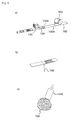
- tampons Fig. 1 can with the below using the Fig. 2 explained devices are produced.
- Fig. 2 In the production of a tampon according to the invention, a cotton wool tape 100 is first drawn into a tampon machine and cut with a cotton trowel 102 to the length required for producing individual tampons, as in FIG Fig. 2a indicated by the dashed lines 100a.
- the pressed and substantially cylindrical blank thus obtained is pressed out of the press with a pusher to the rear and transferred to a tube drum 124.
- the blank is pressed with plungers 126 in a predetermined order in molds of a dome forming device.
- the desired dome shape and execution of the Tampons are in the Kuppenform Skelets.
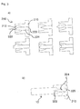
- the molds used in a device according to the invention for the production of tampons according to the invention are described below with reference to FIGS Fig. 3 explained.
- the mandrel assembly consists of a mandrel 222 and a mandrel carrier 224.
- the shell 210 has an inner boundary surface 212 with at least partially in the axial direction tapered inner diameter. Overall, the jacket 210 is rotationally symmetrical.
- the invention is not limited to the embodiment explained with reference to the drawing. Rather, it is also thought to use tampons with different shape of the grooves 14 and / or different cross-sectional shape of the recess 20. It can depressions with any, in particular triangular, square or rectangular cross section are used. In the illustrated with reference to the drawing embodiment of the invention, the recess 20 passes through the dome 12 completely. In other embodiments of the invention, the recess 20 beyond the dome in the Extend absorber core. In some cases, it is also advantageous if the depression 20 penetrates only a part of the dome 12. To produce tampons according to the invention, tampon blanks are introduced into a mold according to the invention.
- the depression can be carried out in several steps by the tampon blank is executed sequentially in identical or differently executed molding tools.
- the molds can be arranged on a molding drum, which is brought by rotation about an axis of rotation in a tampon opposite position, so that the tampon can be introduced by axial relative movement between the mold and blank sequentially in different molds.
Abstract
Description
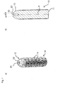
Die Erfindung betrifft ein Tampon zum Einführen in eine Körperhöhle, insbesondere in die weibliche Scheide, mit einem im wesentlichen zylindrischen Saugkörper, der eine sich in Richtung auf ein axiales Ende davon verjüngende Kuppe aufweist, sowie eine Vorrichtung zum Herstellen derartiger Tampons.The invention relates to a tampon for insertion into a body cavity, in particular in the female vagina, having a substantially cylindrical absorbent body having a tip tapering towards an axial end thereof, and a device for producing such tampons.
Tampons der gerade beschriebenen Art werden zur Aufnahme von Körperflüssigkeit in der Wundversorgung, maßgeblich aber im Zusammenhang mit der weiblichen Menstruation eingesetzt. Dabei trifft die Menstruationsflüssigkeit von außen auf den Tampon und dringt von außen nach innen in den Saugkörper ein. Demnach gelangt die Flüssigkeit durch die äußeren Tamponschichten in den üblicherweise verdichteten Tamponkern, welcher das größte Absorptionsvermögen aufweist. Allerdings besteht bei der Verwendung herkömmlicher Tampons das Risiko, daß die äußeren Schichten des Tampons bereits mit Flüssigkeit gesättigt sind, bevor die Flüssigkeit zum Tamponkern vordringt und dann die Gefahr des Auslaufens von Flüssigkeit auftritt, obwohl der Saugkern des Saugkörpers noch nicht mit Flüssigkeit gesättigt bzw. vollständig benutzt ist.Tampons of the type just described are used to absorb body fluid in the wound care, but mainly in the context of female menstruation. The menstrual fluid hits the tampon from the outside and penetrates from the outside to the inside of the absorbent body. Accordingly, the liquid passes through the outer tampon layers in the usually compacted tampon core, which has the greatest absorption capacity. However, the use of conventional tampons involves the risk that the outer layers of the tampon are already saturated with liquid before the liquid penetrates to the tampon core and then the risk of Leakage of liquid occurs, although the absorbent core of the absorbent body is not yet saturated with liquid or completely used.
Zur Behebung dieses Mangels wurden bereits Tampons vorgeschlagen, deren Saugkörper sich parallel zur Zylinderachse erstreckende Rillen in ihrer äußeren Begrenzungsfläche aufweisen. Zur Verbesserung der Absorptionseigenschaften von Tampons wurde auch vorgeschlagen, diese Rillen wellenförmig und/oder wendelförmig die Zylinderachse des im wesentlichen zylindrischen Saugkörpers umlaufend auszuführen.To remedy this deficiency tampons have already been proposed, the absorbent body having parallel to the cylinder axis extending grooves in its outer boundary surface. In order to improve the absorption properties of tampons, it has also been proposed to make these grooves wave-shaped and / or helical around the cylinder axis of the essentially cylindrical absorbent body.
Wenngleich mit entsprechend ausgeführten Tampons eine Verbesserung der Absorptionseigenschaften erreicht werden kann, hat es sich gezeigt, daß weiterhin das Auslaufen von Körperflüssigkeit aus der mit dem Tampon zu verschließenden Körperhöhle beobachtet wird, obwohl das Absorptionsvermögen des Tampons noch nicht vollständig ausgenutzt ist.Although improvement in absorption characteristics can be achieved with appropriately designed tampons, it has been found that leakage of body fluid from the body cavity to be closed with the tampon continues to be observed, although the absorbency of the tampon has not been fully exploited.
In der
In der
Ähnliche Tampons sind in der
Endlich sind in der
Es hat sich allerdings gezeigt, daß die mit diesen Tampons angestrebte Verbesserung des Saugvermögens mit der beschriebenen Tampongeometrie nicht erreicht werden kann und weiterhin das Auslaufen von Körperflüssigkeit aus der Körperhöhle beobachtet wird, selbst wenn das Absorptionsvermögen des Tampons noch nicht vollständig ausgenutzt ist.It has been found, however, that the improvement in absorbency desired with these tampons can not be achieved with the described tampon geometry and, moreover, the leakage of body fluid from the body cavity is observed, even if the absorbency of the tampon has not been fully utilized.
Angesichts dieser Probleme im Stand der Technik liegt der Erfindung die Aufgabe zugrunde, einen Tampon bereitzustellen, dessen Absorptionsfähigkeit optimal ausgenutzt werden kann, und eine Vorrichtung zum Herstellen entsprechender Tampons anzugeben.In view of these problems in the prior art, the object of the invention is to provide a tampon, the absorption capacity of which can be optimally utilized, and to provide a device for producing corresponding tampons.
Erfindungsgemäß wird diese Aufgabe durch eine Weiterbildung bekannter Tampons gelöst, die im wesentlichen dadurch gekennzeichnet ist, daß der Durchmesser der Vertiefung an ihrem dem Scheitelbereich zugewandten Rand etwa 10 bis 45 %, vorzugsweise etwa 20 bis 40 %, besonders bevorzugt etwa 25 bis 35 % des Saugkörperdurchmessers beträgt.According to the invention, this object is achieved by a further development of known tampons, which is characterized essentially in that the diameter of the depression at its edge region facing the edge portion about 10 to 45%, preferably about 20 to 40%, more preferably about 25 to 35% of Saugkörperdurchmessers is.
Die Erfindung geht auf die Erkenntnis zurück, daß die mangelhaften Absorptionseigenschaften herkömmlicher Tampons darauf zurückzuführen sind, daß gerade im Kuppenbereich eine rasche Sättigung in den Randschichten des Tampons auftritt, die dann dazu führt, daß die Körperflüssigkeit am Tampon insgesamt vorbeiströmt und aus der zu verschließenden Körperhöhe ausläuft. Durch die erfindungsgemäße Weiterbildung wird im Kuppenbereich ein Trichter bzw. Saugkanal zur Verfügung gestellt, durch den die dort auftreffende Körperflüssigkeit, insbesondere Menstruationsflüssigkeit, direkt in den Saugkern des Saugkörpers gelangt, so daß eine frühzeitige Sättigung des äußeren Bereichs des Saugkörpers im Kuppenbereich zuverlässig verhindert werden kann und auch der innere Bereich des Tampons optimal genutzt werden kann. Dabei hat sich im besonderen gezeigt, daß durch die Bereitstellung der Vertiefung, d. h. eines konkaven Oberflächenbereichs im Bereich der ansonsten konvexen Tamponkuppe keine nennenswerten Beeinträchtigungen der Einführeigenschaften des Tampons, welche durch die Kuppe verbessert werden sollen, beobachtet werden. Insgesamt wird durch die erfindungsgemäße Weiterbildung von Tampons also die Absorptionseigenschaft des Tampons verbessert, ohne dessen sonstige Gebrauchseigenschaften zu beeinträchtigen.The invention is based on the recognition that the inadequate absorption properties of conventional tampons are due to the fact that especially in the tip area a rapid saturation occurs in the marginal layers of the tampon, which then causes the body fluid flows past the tampon in total and from the body height to be closed expires. The development according to the invention provides a funnel or suction channel in the tip area, through which the body fluid, in particular menstrual fluid, which is incident there passes directly into the absorbent core of the absorbent body, so that premature saturation of the outer region of the absorbent body in the tip region can be reliably prevented and also the inner area of the tampon can be optimally used. It has been shown in particular that by providing the recess, d. H. a concave surface area in the area of the otherwise convex tampon tip no significant impairment of the insertion characteristics of the tampon, which are to be improved by the dome, are observed. Overall, therefore, the absorption feature of the tampon is improved by the development of tampons according to the invention, without affecting the other useful properties.
Dabei ist der Durchmesser der Vertiefung an ihrem dem Scheitelbereich zugewandten Rand, d. h. der größte Durchmesser der Vertiefung in einer senkrecht zur Zylinderachse des Saugkörpers verlaufenden Richtung, so gewählt, daß er weniger als die Hälfte des Durchmessers des Saugkörpers beträgt. Diese Begrenzung des Vertiefungsdurchmessers geht auf die Erkenntnis zurück, daß die bei Tampons gemäß der
Falls der Durchmesser weniger als 20 % des Saugkörperdurchmessers beträgt, werden Beeinträchtigungen der gewünschten Eigenschaften hinsichtlich der Einleitung von Körperflüssigkeit in den Saugkern beobachtet. Bei einer Vergrößerung des Durchmessers der Vertiefung auf einen Wert von mehr als 40 % des Saugkörperdurchmessers kommt es zu Beeinträchtigungen bei der Einführung des Tampons in die Körperhöhle. Die erfindungsgemäße trichterförmige Verjüngung der Vertiefung hat sich sowohl aus fertigungstechnischen Gründen als auch im Hinblick auf die gewünschte optimale Ausnutzung der Absorptionseigenschaften des Tampons als zweckmäßig erwiesen.If the diameter is less than 20% of the absorbent diameter, impairments of the desired properties with respect to the introduction of body fluid into the absorbent core are observed. Increasing the diameter of the depression to more than 40% of the absorbent diameter will interfere with the insertion of the tampon into the body cavity. The funnel-shaped narrowing of the depression according to the invention has proved to be expedient both for manufacturing reasons and with regard to the desired optimum utilization of the absorption properties of the tampon.
Aus fertigungstechnischer Sicht hat es sich als günstig erwiesen, wenn die erfindungsgemäß in der Tamponkuppe vorgesehene Vertiefung eine mindestens 2-zählige Drehsymmetrie bezüglich einer etwa kolinear zur Längsachse des Saugkörpers verlaufenden Symmetrieachse aufweist, also beispielsweise rechteckförmig ist. Im Hinblick auf eine gute Ausnutzung der Absorptionseigenschaften des Tampons ist es besonders zweckmäßig, wenn die Vertiefung eine 3-zählige Symmetrie mit dreieckförmigem Querschnitt, eine 4-zählige Symmetrie mit quadratischem Querschnitt und besonders bevorzugt eine Rotationssymmetrie mit kreisförmigem Querschnitt aufweist.From a production point of view, it has proved to be advantageous if the recess provided according to the invention in the tampon head has an at least 2-fold rotational symmetry with respect to an axis of symmetry approximately co-linear with the longitudinal axis of the absorbent body, ie is rectangular, for example. In view of a good utilization of the absorption properties of the tampon, it is particularly expedient if the depression has a 3-fold symmetry with a triangular cross-section, a 4-fold symmetry with a square cross section and particularly preferably a rotational symmetry with a circular cross section.
Im Hinblick auf die Optimierung der Einleitung von Körperflüssigkeit in den Saugkern des Saugkörpers hat es sich als zweckmäßig erwiesen, wenn sich die Vertiefung über mindestens 20 % insbesondere mindestens 50 % der axialen Länge der Kuppe erstreckt, die Kuppe vorzugsweise in axialer Richtung vollständig durchsetzt und besonders bevorzugt ausgehend von dem umlaufenden Rand über die Kuppe hinaus in den Saugkern hineinreicht. Dabei kann der Durchmesser der Vertiefung an ihrem die Zylinderachse umlaufenden Rand etwa 10 bis 45 %, insbesondere 20 bis 40 % , vorzugsweise etwa 25 bis 35 % des Saugkörperdurchmessers betragen.With regard to the optimization of the introduction of body fluid into the absorbent core of the absorbent body, it has proved to be expedient if the depression extends over at least 20%, in particular at least 50%, of the axial length of the dome, preferably fully penetrating the dome in the axial direction and especially preferably extends from the peripheral edge beyond the dome out into the absorbent core. In this case, the diameter of the recess at its circumferential axis of the cylinder Edge about 10 to 45%, in particular 20 to 40%, preferably about 25 to 35% of the Saugkörperdurchmessers amount.
Durch die Bereitstellung der Vertiefung in dem Tampon kann sich eine Verminderung der Menge absorptionsfähigen Materials des Tampons insgesamt ergeben. Im Hinblick auf die Optimierung der Ausnutzung der Absorptionsfähigkeit hat es sich als zweckmäßig erwiesen, wenn das Volumen der Vertiefung 4 % oder weniger, vorzugsweise 2 % oder weniger, besonders bevorzugt 1 % oder weniger, insbesondere 0,75 % oder weniger des Gesamtvolumens des Tampons entspricht. Dabei wird der gewünschte Effekt der Verbesserung der Einleitung von Körperflüssigkeit in den Tamponkern noch sichergestellt, wenn das Volumen der Vertiefung 0,1 % oder mehr, insbes. 0,2 % oder mehr, vorzugsweise 0,5 % oder mehr des Gesamtvolumens des Tampons entspricht.Providing the depression in the tampon may result in a reduction in the amount of absorbent material of the tampon as a whole. With regard to the optimization of the utilization of the absorption capacity, it has proved expedient if the volume of the depression is 4% or less, preferably 2% or less, particularly preferably 1% or less, in particular 0.75% or less, of the total volume of the tampon equivalent. In this case, the desired effect of improving the introduction of body fluid into the tampon core is still ensured if the volume of the depression corresponds to 0.1% or more, especially 0.2% or more, preferably 0.5% or more, of the total volume of the tampon ,
Ähnlich wie bei herkömmlichen Tampons kann auch ein erfindungsgemäßer Tampon ein eine Mantelfläche des Saugkörpers abdeckendes Hüllmaterial, wie etwa ein auf Watte aufsiegelbares Hüllvlies oder eine vorzugsweise perforierte Hüllfolie, aufweisen, mit dem verhindert wird, daß Tamponfasern sich aus dem Tamponkörper lösen, wenn der Tampon sich im Rahmen der Aufnahme von Körperflüssigkeit ausdehnt. Im Rahmen der Erfindung einsetzbare Hüllmaterialien sind bspw. in der
Herkömmliche Tampons werden hergestellt, indem zunächst ein Hüllvlies auf ein Watteband aufgesiegelt wird, so daß das Hüllvlies sich über die Hälfte der Länge eines Wattebandstreifens erstreckt, der für die Herstellung eines Tampons benötigt wird und über den Wattestreifen hinausreicht. Beim nächsten Herstellungsschritt wird aus dem Wattestreifen ein Wattewickel gebildet, bei dem das Hüllvlies eine äußere Begrenzungsfläche des Wickels bildet, welcher den Wattestreifen überlappt und auf eine vorherige Wickellage des Hüllvlieses aufgesiegelt werden kann, um so eine umlaufende äußere Begrenzungsfläche des Wattewickels zu bilden. Anschließend wird der Wickel verpreßt, insbesondere radial und/oder linear verpreßt, um so einen etwa zylindrischen Saugkörper bereitzustellen. Im Rahmen der radialen Verpressung werden auch die ggf. vorzusehenden Rillen in der Mantelfläche des Saugkörpers gebildet. Zur Fertigstellung des Tampons wird der bereits gepresste Tamponrohling in Formwerkzeuge einer Kuppenformeinrichtung eingeführt, deren Form der gewünschten Kuppenform entspricht.Conventional tampons are made by first sealing an envelope to a cotton swathe so that the enveloping fabric extends over half the length of a cotton swathe strip needed to make a tampon and extend beyond the swathe. In the next manufacturing step, a wadding roll is formed from the cotton strip, wherein the Hüllvlies forms an outer boundary surface of the roll, which overlaps the cotton strip and a previous winding layer of Hüllvlieses can be sealed so as to form a circumferential outer boundary surface of the lap roll. Subsequently, the winding is pressed, in particular pressed radially and / or linearly so as to provide an approximately cylindrical absorbent body. As part of the radial compression and possibly provided grooves are formed in the lateral surface of the absorbent body. To complete the tampon already pressed tampon blank is introduced into molds a dome forming device whose shape corresponds to the desired dome shape.
Eine erfindungsgemäße Vorrichtung zur Herstellung eines erfindungsgemäßen Tampons mit einer Kuppenformeinrichtung zum Formen einer Kuppe an einem im wesentlichen zylindrischen und bereits gepreßten Tamponrohling, bei dem die Kuppenformeinrichtung mindestens ein Formwerkzeug mit einem beim Formvorgang in Richtung der Zylinderachse des Rohlings in den Rohling einführbaren Dorn aufweist, um so die das Einleiten der Menstruationsflüssigkeit in den Saugkörperkern begünstigende Vertiefung bzw. den entsprechenden trichterförmigen Einleitungskanal in der Tamponkuppe zu bilden, ist im wesentlichen dadurch gekennzeichnet, daß das Formwerkzeug einen ringförmigen Mantel mit sich zumindest abschnittweise in axialer Richtung verjüngendem Innendurchmesser und einem in den Mantel einsetzbaren Dorn aufweist.A device according to the invention for producing a tampon according to the invention with a dome forming device for forming a dome on a substantially cylindrical and already pressed tampon blank, wherein the dome forming means comprises at least one mold with a mandrel insertable into the blank during the molding operation in the direction of the cylinder axis of the blank so as to form the introduction of the menstrual fluid into the absorbent core favoring recess or the corresponding funnel-shaped inlet channel in the tampon cap, is essentially characterized in that the mold has an annular jacket with at least partially tapered in the axial direction inner diameter and an insertable into the jacket Thorn has.
Das erfindungsgemäße Formwerkzeug ist demnach modular aufgebaut. Dabei wird durch den Mantel die äußere konvexe und das Einführen des Tampons in die Körperhöhle begünstigende Oberfläche der Kuppe gebildet, während durch den in den Mantel eingesetzten Dorn die Vertiefung gebildet wird, mit der die Einleitung von Menstruationsflüssigkeit in den Saugkörperkern begünstigt wird. Durch den modularen Aufbau kann erreicht werden, daß bei einem mehrstufigen Herstellungsprozeß, bei dem der Saugkörper nacheinander in eine Anzahl von Werkzeugen eingesetzt wird unter Verwendung ein und desselben Mantels unterschiedliche Dornformen eingesetzt werden können. Bei dem beschriebenen modular aufgebauten Formwerkzeug kann der Erhalt der gewünschten Kuppenform besonders zuverlässig sichergestellt werden, wenn zwischen dem den sich verjüngenden Innendurchmesser aufweisenden Bereich der inneren Begrenzungsfläche des Mantels und dem Dorn ein Ringspalt freigelassen ist und der Mantelinnenraum an einem dem Dorn abgewandten axialen Ende mit einem vorzugsweise einstückig mit dem Dorn ausgeführten Dornträger verschlossen ist. Gegebenenfalls kann der Dorn in axialer Richtung über den dem Dornträger abgewandten Rand des Mantels hinausragen, um so eine die Kuppe vollständig durchsetzende und ggf. über die Kuppe hinausragende Vertiefung in der Kuppe zu bilden. Wie vorstehend bereits angedeutet, kann die Kuppenformeinrichtung zwei, drei oder mehr Formwerkzeuge aufweisen, in die die Rohlinge beim Formvorgang nacheinander einführbar sind.The mold according to the invention is therefore modular. In this case, the outer convex and the insertion of the tampon into the body cavity-promoting surface of the dome is formed by the shell, while the depression is formed by the mandrel inserted into the shell, with which the introduction of menstrual fluid is promoted in the absorbent core. Due to the modular structure can be achieved that in a multi-stage manufacturing process in which the absorbent body is successively used in a number of tools using one and the same shell different mandrel shapes can be used. In the modular mold described described the preservation of the desired dome shape can be ensured particularly reliable if between the tapered inner diameter having region of the inner boundary surface of the shell and the mandrel, an annular gap is released and the shell interior at a side facing away from the mandrel axial end with a preferably integrally with the mandrel executed mandrel carrier is closed. Optionally, the mandrel may protrude in the axial direction beyond the edge of the jacket facing away from the mandrel carrier, so as to form a depression in the dome which passes completely through the dome and optionally protrudes beyond the dome. As already indicated above, the dome forming device may have two, three or more molding tools, in which the blanks are successively inserted during the molding process.
Im Hinblick auf die Vereinfachung des Herstellungsvorgangs beim Einsatz mehrerer Formwerkzeuge sind diese zweckmäßigerweise an einem gemeinsamen Träger angeordnet, der bezüglich einer Drehachse drehbar gelagert ist, wobei die Formwerkzeug auf einer die Drehachse umlaufenden Kreislinie angeordnet sind. Dann können die Formwerkzeug durch Drehen des Trägers in dem Rohling gegenüberliegende Position gebracht werden und durch eine axiale Relativbewegung zwischen Rohling und Formwerkzeug der gewünschte Formgebungsvorgang eingeleitet werden.With regard to the simplification of the manufacturing process when using a plurality of molds, these are expediently arranged on a common carrier, which is rotatably mounted with respect to a rotation axis, wherein the mold are arranged on a circumference surrounding the axis of rotation. Then the mold can be brought by rotating the carrier in the blank opposite position and initiated by an axial relative movement between the blank and the mold of the desired shaping operation.
Ein erfindungsgemäßes Formwerkzeug für eine erfindungsgemäße Vorrichtung ist im wesentlichen dadurch gekennzeichnet, daß es einen ringförmigen Mantel mit einem darin eingesetzten Dorn aufweist, wobei der Dorn zweckmäßigerweise austauschbar in dem Mantel aufgenommen ist. Ein erfindungsgemäßer Tampon wird, wie der vorstehenden Erläuterung zu entnehmen ist, hergestellt, in dem ein im wesentlichen zylindrischer und bereits radial und/oder linear gepreßter Tamponrohling in ein erfindungsgemäßes Formwerkzeug in axialer Richtung eingeführt wird.An inventive mold for a device according to the invention is essentially characterized in that it comprises an annular jacket with a mandrel inserted therein, wherein the mandrel is suitably received interchangeable in the jacket. A tampon according to the invention, as the above explanation can be seen, produced in which a substantially cylindrical and already radially and / or linearly pressed tampon blank is introduced into a mold according to the invention in the axial direction.
Nachstehend wird die Erfindung unter Bezugnahme auf die Zeichnung, auf die hinsichtlich aller erfindungswesentlichen und in der Beschreibung nicht näher herausgestellten Einzelheiten ausdrücklich verwiesen wird, erläutert.The invention will be explained with reference to the drawing, to which reference is expressly made with respect to all essential to the invention and in the description unspecified highlighted details.
In der Zeichnung zeigt:
- Fig.
- 1 eine schematische Darstellung eines erfindungsgemäßen Tampons,
- Fig. 2
- eine schematische Darstellung einer erfindungsgemäßen Vorrichtung zum Herstellen erfindungsgemäßer Tampons und
- Fig. 3
- schematische Darstellungen erfindungsgemäßer Formwerkzeug.
- FIG.
- 1 is a schematic representation of a tampon according to the invention,
- Fig. 2
- a schematic representation of an apparatus according to the invention for producing tampons according to the invention and
- Fig. 3
- schematic representations of inventive mold.
Gemäß
Der Durchmesser "d" der Vertiefung an ihrem dem Scheitelbereich zugewandten Rand (22), d. h. der größte Durchmesser der Vertiefung in einer sich senkrecht zur Zylinderachse "A" erstreckenden Richtung, beträgt bei der in der Zeichnung dargestellten Ausführungsform der Erfindung etwa 30 % des Saugkörperdurchmessers.The diameter "d" of the depression at its edge (22) facing the apex region, d. H. the largest diameter of the recess in a direction perpendicular to the cylinder axis "A" extending direction, in the embodiment of the invention shown in the drawing is about 30% of the Saugkörperdurchmessers.
Tampons gemäß
Nach Schneiden des Wattebands zu Wattestreifen mit der benötigten Länge wird ein Hüllvlies 104 mit etwa der halben Länge der Wattestreifen versetzt um die halbe Länge eines Wattebandstreifens unter Druck und Hitze mit Hilfe einer Siegelbacke 106 auf das Watteband 100 aufgesiegelt. Das Hüllvlies ragt in Längsrichtung über den Wattestreifen hinaus, auf dem es aufgesiegelt ist. In einem nächsten Herstellungsschritt wird ein Rückholfaden 108 um den Wattestreifen 100 geschlungen und verknotet, wie in
Der so vorbereitete Wattewickel 120 wird an eine geöffnete Presse 122 übergeben, wie in
Nach leichtem Anlüften der Presse 120 wird der damit erhaltene gepreßte und im wesentlichen zylinderförmige Rohling mit einem Ausschieber nach hinten aus der Presse gedrückt und an eine Röhrchentrommel 124 übergeben. In einer Kopftrommel 125 wird der Rohling mit Stößeln 126 in vorgegebener Reihenfolge in Formwerkzeuge einer Kuppenformeinrichtung gedrückt. Abhängig von der gewünschten Kuppenform und Ausführung des Tampons sind in der Kuppenformeinrichtung 128 4 bis 12 gleiche oder auch unterschiedliche Formwerkzeug eingebaut.After a slight airing of the
Die in einer erfindungsgemäßen Vorrichtung zur Herstellung erfindungsgemäßer Tampons zum Einsatz kommenden Formwerkzeuge werden nachstehend anhand der
Die Erfindung ist nicht auf das anhand der Zeichnung erläuterte Ausführungsbeispiel beschränkt. Vielmehr ist auch daran gedacht, Tampons mit unterschiedlicher Form der Rillen 14 und/oder unterschiedlicher Querschnittsform der Vertiefung 20 einzusetzen. Es können Vertiefungen mit beliebigem, insbesondere dreieckigem, quadratischem oder rechteckigem Querschnitt zum Einsatz kommen. Bei dem anhand der Zeichnung erläuterten Ausführungsbeispiel der Erfindung durchsetzt die Vertiefung 20 die Kuppe 12 vollständig. Bei anderen Ausführungsformen der Erfindung kann die Vertiefung 20 über die Kuppe hinaus in den Saugkörperkern hineinreichen. In einigen Fällen ist es auch günstig, wenn die Vertiefung 20 nur einen Teil der Kuppe 12 durchsetzt. Zur Herstellung erfindungsgemäßer Tampons werden Tamponrohlinge in ein erfindungsgemäßes Formwerkzeug eingeführt. Dabei kann die Vertiefung in mehreren Schritten ausgeführt werden, indem der Tamponrohling nacheinander in identisch oder unterschiedlich ausgeführte Formwerkzeuge ausgeführt wird. Die Formwerkzeuge können dabei auf einer Formwerkzeugtrommel angeordnet sein, welche durch Drehen um eine Drehachse in eine dem Tampon gegenüberliegende Stellung gebracht wird, so daß der Tampon durch axiale Relativbewegung zwischen Formwerkzeug und Rohling nacheinander in unterschiedliche Formwerkzeuge eingeführt werden kann.The invention is not limited to the embodiment explained with reference to the drawing. Rather, it is also thought to use tampons with different shape of the
Claims (15)
Priority Applications (3)
| Application Number | Priority Date | Filing Date | Title |
|---|---|---|---|
| PL10009402T PL2298259T3 (en) | 2009-09-09 | 2010-09-09 | Device for manufacturing of a tampon |
| PL11007729T PL2417954T3 (en) | 2009-09-09 | 2010-09-09 | Tampon |
| EP11007729.4A EP2417954B1 (en) | 2009-09-09 | 2010-09-09 | Tampon |
Applications Claiming Priority (1)
| Application Number | Priority Date | Filing Date | Title |
|---|---|---|---|
| DE202009012237U DE202009012237U1 (en) | 2009-09-09 | 2009-09-09 | Tampon and device for making a tampon |
Related Child Applications (1)
| Application Number | Title | Priority Date | Filing Date |
|---|---|---|---|
| EP11007729.4 Division-Into | 2011-09-22 |
Publications (3)
| Publication Number | Publication Date |
|---|---|
| EP2298259A2 true EP2298259A2 (en) | 2011-03-23 |
| EP2298259A3 EP2298259A3 (en) | 2011-09-14 |
| EP2298259B1 EP2298259B1 (en) | 2013-01-23 |
Family
ID=42813957
Family Applications (2)
| Application Number | Title | Priority Date | Filing Date |
|---|---|---|---|
| EP11007729.4A Active EP2417954B1 (en) | 2009-09-09 | 2010-09-09 | Tampon |
| EP10009402A Active EP2298259B1 (en) | 2009-09-09 | 2010-09-09 | Device for manufacturing of a tampon |
Family Applications Before (1)
| Application Number | Title | Priority Date | Filing Date |
|---|---|---|---|
| EP11007729.4A Active EP2417954B1 (en) | 2009-09-09 | 2010-09-09 | Tampon |
Country Status (3)
| Country | Link |
|---|---|
| EP (2) | EP2417954B1 (en) |
| DE (1) | DE202009012237U1 (en) |
| PL (2) | PL2298259T3 (en) |
Cited By (9)
| Publication number | Priority date | Publication date | Assignee | Title |
|---|---|---|---|---|
| DE202012011679U1 (en) | 2012-12-05 | 2013-02-06 | Rauscher Consumer Products Gmbh | Tampon and device for making a tampon |
| DE102012023812A1 (en) | 2012-12-05 | 2014-06-05 | Rauscher Consumer Products Gmbh | Method and device for producing a tampon and tampon produced therewith |
| DE202015001935U1 (en) | 2015-03-11 | 2016-06-14 | Rauscher Consumer Products Gmbh | Apparatus for producing a tampon and tampon produced therewith |
| WO2018202382A1 (en) | 2017-05-04 | 2018-11-08 | Rauscher Consumer Products Gmbh | Tampon and method for producing a tampon |
| DE102018107634A1 (en) | 2018-03-29 | 2019-10-02 | Rauscher Consumer Products Gmbh | tampon |
| US11007090B2 (en) | 2015-12-31 | 2021-05-18 | Johnson & Johnson Gmbh | Method of winding up tampon material |
| DE202022103393U1 (en) | 2022-05-27 | 2022-07-07 | Rauscher Consumer Products Gmbh | tampon |
| US11565096B2 (en) | 2021-01-14 | 2023-01-31 | Herphoric, Inc. | Delivery system for a pharmaceutical, holistic or medicinal component |
| DE102022113416A1 (en) | 2022-05-27 | 2023-11-30 | Rauscher Consumer Products Gmbh | Tampon and method of making a tampon |
Families Citing this family (2)
| Publication number | Priority date | Publication date | Assignee | Title |
|---|---|---|---|---|
| SI25102A (en) | 2015-12-14 | 2017-06-30 | TomaĹľ Brdnik | Process for producing tampon with integrated therapeutic agent |
| USD977632S1 (en) | 2020-02-26 | 2023-02-07 | Tampro Inc. | Tampon |
Citations (9)
| Publication number | Priority date | Publication date | Assignee | Title |
|---|---|---|---|---|
| US3343225A (en) | 1964-09-01 | 1967-09-26 | Hahn Carl Dr Kg | Apparatus for treating elongated deformable articles |
| US3515138A (en) | 1967-07-05 | 1970-06-02 | Josef Hochstrasser | Process and apparatus for treating elongated deformable articles |
| US4077408A (en) | 1974-01-24 | 1978-03-07 | Murray Jerome L | Catamenial device employing polymeric constraining means |
| US4088132A (en) | 1975-05-07 | 1978-05-09 | W. R. Grace & Co. | Hydrophilic polyurethane foams for use in catamenial devices |
| US4318405A (en) | 1980-07-24 | 1982-03-09 | Sneider Vincent R | Tampon and drug delivery device |
| EP0925050B1 (en) | 1997-06-30 | 2002-09-04 | McNEIL-PPC, Inc. | Tampon having an apertured film cover |
| DE69811114T2 (en) | 1997-12-03 | 2004-01-15 | Johnson & Johnson Gmbh | TAMPON FOR WOMEN'S HYGIENE OR MEDICAL PURPOSES AND METHOD FOR THE PRODUCTION THEREOF |
| US6860874B2 (en) | 2001-02-15 | 2005-03-01 | Johnson & Johnson Gmbh | Tampon, particularly for feminine hygiene |
| EP1194100B1 (en) | 1999-06-30 | 2008-02-20 | JOHNSON & JOHNSON GmbH | Tampon having an apertured film cover thermobonded to a fibrous absorbent structure |
Family Cites Families (6)
| Publication number | Priority date | Publication date | Assignee | Title |
|---|---|---|---|---|
| US2386590A (en) | 1940-10-12 | 1945-10-09 | Calhoun Vernon | Catamenial device |
| US4018225A (en) * | 1975-08-18 | 1977-04-19 | The Gillette Company | Catamenial tampon |
| GB2056283A (en) * | 1979-07-23 | 1981-03-18 | Kimberly Clark Co | Tampon |
| US4335720A (en) | 1980-04-09 | 1982-06-22 | Glassman Jacob A | Catamenial tampon with hollow core |
| US5634248A (en) * | 1995-07-14 | 1997-06-03 | Playtex Products, Inc. | Method for post forming a rounded insertion end of a tampon pledget of an open-ended applicator |
| US20040030280A1 (en) | 2002-08-08 | 2004-02-12 | Mercier Thomas G. | Leak resistant tampon system |
-
2009
- 2009-09-09 DE DE202009012237U patent/DE202009012237U1/en not_active Expired - Lifetime
-
2010
- 2010-09-09 PL PL10009402T patent/PL2298259T3/en unknown
- 2010-09-09 EP EP11007729.4A patent/EP2417954B1/en active Active
- 2010-09-09 PL PL11007729T patent/PL2417954T3/en unknown
- 2010-09-09 EP EP10009402A patent/EP2298259B1/en active Active
Patent Citations (9)
| Publication number | Priority date | Publication date | Assignee | Title |
|---|---|---|---|---|
| US3343225A (en) | 1964-09-01 | 1967-09-26 | Hahn Carl Dr Kg | Apparatus for treating elongated deformable articles |
| US3515138A (en) | 1967-07-05 | 1970-06-02 | Josef Hochstrasser | Process and apparatus for treating elongated deformable articles |
| US4077408A (en) | 1974-01-24 | 1978-03-07 | Murray Jerome L | Catamenial device employing polymeric constraining means |
| US4088132A (en) | 1975-05-07 | 1978-05-09 | W. R. Grace & Co. | Hydrophilic polyurethane foams for use in catamenial devices |
| US4318405A (en) | 1980-07-24 | 1982-03-09 | Sneider Vincent R | Tampon and drug delivery device |
| EP0925050B1 (en) | 1997-06-30 | 2002-09-04 | McNEIL-PPC, Inc. | Tampon having an apertured film cover |
| DE69811114T2 (en) | 1997-12-03 | 2004-01-15 | Johnson & Johnson Gmbh | TAMPON FOR WOMEN'S HYGIENE OR MEDICAL PURPOSES AND METHOD FOR THE PRODUCTION THEREOF |
| EP1194100B1 (en) | 1999-06-30 | 2008-02-20 | JOHNSON & JOHNSON GmbH | Tampon having an apertured film cover thermobonded to a fibrous absorbent structure |
| US6860874B2 (en) | 2001-02-15 | 2005-03-01 | Johnson & Johnson Gmbh | Tampon, particularly for feminine hygiene |
Cited By (11)
| Publication number | Priority date | Publication date | Assignee | Title |
|---|---|---|---|---|
| DE202012011679U1 (en) | 2012-12-05 | 2013-02-06 | Rauscher Consumer Products Gmbh | Tampon and device for making a tampon |
| DE102012023812A1 (en) | 2012-12-05 | 2014-06-05 | Rauscher Consumer Products Gmbh | Method and device for producing a tampon and tampon produced therewith |
| EP2740448A1 (en) | 2012-12-05 | 2014-06-11 | Rauscher Consumer Products GmbH | Method and apparatus for making a tampon and tampon made by this |
| DE202015001935U1 (en) | 2015-03-11 | 2016-06-14 | Rauscher Consumer Products Gmbh | Apparatus for producing a tampon and tampon produced therewith |
| EP3067025A1 (en) | 2015-03-11 | 2016-09-14 | Rauscher Consumer Products GmbH | Method and apparatus for making a tampon and tampon made by this |
| US11007090B2 (en) | 2015-12-31 | 2021-05-18 | Johnson & Johnson Gmbh | Method of winding up tampon material |
| WO2018202382A1 (en) | 2017-05-04 | 2018-11-08 | Rauscher Consumer Products Gmbh | Tampon and method for producing a tampon |
| DE102018107634A1 (en) | 2018-03-29 | 2019-10-02 | Rauscher Consumer Products Gmbh | tampon |
| US11565096B2 (en) | 2021-01-14 | 2023-01-31 | Herphoric, Inc. | Delivery system for a pharmaceutical, holistic or medicinal component |
| DE202022103393U1 (en) | 2022-05-27 | 2022-07-07 | Rauscher Consumer Products Gmbh | tampon |
| DE102022113416A1 (en) | 2022-05-27 | 2023-11-30 | Rauscher Consumer Products Gmbh | Tampon and method of making a tampon |
Also Published As
| Publication number | Publication date |
|---|---|
| DE202009012237U1 (en) | 2010-09-30 |
| EP2417954B1 (en) | 2013-07-03 |
| EP2417954A1 (en) | 2012-02-15 |
| EP2298259B1 (en) | 2013-01-23 |
| EP2298259A3 (en) | 2011-09-14 |
| PL2417954T3 (en) | 2013-12-31 |
| PL2298259T3 (en) | 2013-09-30 |
Similar Documents
| Publication | Publication Date | Title |
|---|---|---|
| EP2298259B1 (en) | Device for manufacturing of a tampon | |
| DE10114786C2 (en) | Feminine hygiene tampon and method and apparatus for making the same | |
| DE10244874C5 (en) | Method and device for producing a tampon for feminine hygiene | |
| DE4304505C2 (en) | Tampon, in particular for feminine hygiene, and method and device for producing the same | |
| DE2633039C3 (en) | V-belt pulley formed from a cup-shaped sheet metal part and process for its manufacture | |
| DE3029770A1 (en) | MENSTRUATION TAMPONS | |
| AT508682B1 (en) | PRESS FOR THE MANUFACTURE OF A TAMPON | |
| EP2448538B1 (en) | Process for final forming of a tampon | |
| EP2199222B1 (en) | Paper beaker and method and device for producing same | |
| DE69333500T2 (en) | tampon | |
| WO1982002336A1 (en) | Device for introducing a pad blank in a pad press | |
| DE1750662B2 (en) | METHOD OF MANUFACTURING A CUP-SHAPED PISTON | |
| EP1912606B1 (en) | Method for producing a tampon wrapped in a protective cover | |
| EP2740448B1 (en) | Method and apparatus for making a tampon and tampon made by this | |
| EP3305434B1 (en) | Cassette adapted to receive a profile role set or pressure forming set to adjust the shape of a lamellae carrier or the like and corresponding deformation tool | |
| DE202012011679U1 (en) | Tampon and device for making a tampon | |
| DE1165809B (en) | Process for the manufacture of menstrual tampons | |
| AT11566U1 (en) | TAMPON AND DEVICE FOR MAKING A TAMPON | |
| DE10151756C1 (en) | Tampon making machine comprises cylindrical press made up of radial jaws, piston for ejecting tampons from press having central pressing face and star-shaped additional pressing face | |
| DE1962926B2 (en) | METHOD OF MANUFACTURING A BRUSH | |
| EP3556333B1 (en) | Tampon | |
| DE1541302A1 (en) | Means for the monthly hygiene of women and processes for their preparation | |
| DE1302526C2 (en) | TOOL FOR EXTRUSION OF SOLID CAGES FOR SPHERICAL ROLLER BEARINGS | |
| DE2324882B2 (en) | METHOD FOR MANUFACTURING A TAMPON AND DEVICE FOR CARRYING OUT THE METHOD | |
| DE3633661A1 (en) | Compressed rod-shaped tampon for female hygiene |
Legal Events
| Date | Code | Title | Description |
|---|---|---|---|
| PUAI | Public reference made under article 153(3) epc to a published international application that has entered the european phase |
Free format text: ORIGINAL CODE: 0009012 |
|
| 17P | Request for examination filed |
Effective date: 20100909 |
|
| AK | Designated contracting states |
Kind code of ref document: A2 Designated state(s): AL AT BE BG CH CY CZ DE DK EE ES FI FR GB GR HR HU IE IS IT LI LT LU LV MC MK MT NL NO PL PT RO SE SI SK SM TR |
|
| AX | Request for extension of the european patent |
Extension state: BA ME RS |
|
| PUAL | Search report despatched |
Free format text: ORIGINAL CODE: 0009013 |
|
| PUAF | Information related to the publication of a search report (a3 document) modified or deleted |
Free format text: ORIGINAL CODE: 0009199SEPU |
|
| AK | Designated contracting states |
Kind code of ref document: A3 Designated state(s): AL AT BE BG CH CY CZ DE DK EE ES FI FR GB GR HR HU IE IS IT LI LT LU LV MC MK MT NL NO PL PT RO SE SI SK SM TR |
|
| AX | Request for extension of the european patent |
Extension state: BA ME RS |
|
| RIC1 | Information provided on ipc code assigned before grant |
Ipc: A61F 13/20 20060101AFI20110707BHEP |
|
| PUAL | Search report despatched |
Free format text: ORIGINAL CODE: 0009013 |
|
| D17D | Deferred search report published (deleted) | ||
| AK | Designated contracting states |
Kind code of ref document: A3 Designated state(s): AL AT BE BG CH CY CZ DE DK EE ES FI FR GB GR HR HU IE IS IT LI LT LU LV MC MK MT NL NO PL PT RO SE SI SK SM TR |
|
| AX | Request for extension of the european patent |
Extension state: BA ME RS |
|
| RIC1 | Information provided on ipc code assigned before grant |
Ipc: A61F 13/20 20060101AFI20110809BHEP |
|
| 17Q | First examination report despatched |
Effective date: 20120518 |
|
| GRAP | Despatch of communication of intention to grant a patent |
Free format text: ORIGINAL CODE: EPIDOSNIGR1 |
|
| RIN1 | Information on inventor provided before grant (corrected) |
Inventor name: POSCH, KARL-HEINZ Inventor name: MIKULASCHEK, MARLENE SOPHIE Inventor name: STEINLECHNER, ERIK Inventor name: SUESSLE, WOLFGANG Inventor name: POETSCH, ERNST |
|
| GRAS | Grant fee paid |
Free format text: ORIGINAL CODE: EPIDOSNIGR3 |
|
| GRAA | (expected) grant |
Free format text: ORIGINAL CODE: 0009210 |
|
| AK | Designated contracting states |
Kind code of ref document: B1 Designated state(s): AL AT BE BG CH CY CZ DE DK EE ES FI FR GB GR HR HU IE IS IT LI LT LU LV MC MK MT NL NO PL PT RO SE SI SK SM TR |
|
| REG | Reference to a national code |
Ref country code: GB Ref legal event code: FG4D Free format text: NOT ENGLISH |
|
| REG | Reference to a national code |
Ref country code: CH Ref legal event code: EP |
|
| REG | Reference to a national code |
Ref country code: AT Ref legal event code: REF Ref document number: 594550 Country of ref document: AT Kind code of ref document: T Effective date: 20130215 Ref country code: CH Ref legal event code: EP |
|
| REG | Reference to a national code |
Ref country code: IE Ref legal event code: FG4D Free format text: LANGUAGE OF EP DOCUMENT: GERMAN |
|
| REG | Reference to a national code |
Ref country code: DE Ref legal event code: R096 Ref document number: 502010002178 Country of ref document: DE Effective date: 20130321 |
|
| REG | Reference to a national code |
Ref country code: CH Ref legal event code: NV Representative=s name: WERNER FENNER PATENTANWALT, CH |
|
| REG | Reference to a national code |
Ref country code: LT Ref legal event code: MG4D |
|
| REG | Reference to a national code |
Ref country code: NL Ref legal event code: VDEP Effective date: 20130123 |
|
| PG25 | Lapsed in a contracting state [announced via postgrant information from national office to epo] |
Ref country code: IS Free format text: LAPSE BECAUSE OF FAILURE TO SUBMIT A TRANSLATION OF THE DESCRIPTION OR TO PAY THE FEE WITHIN THE PRESCRIBED TIME-LIMIT Effective date: 20130523 Ref country code: SE Free format text: LAPSE BECAUSE OF FAILURE TO SUBMIT A TRANSLATION OF THE DESCRIPTION OR TO PAY THE FEE WITHIN THE PRESCRIBED TIME-LIMIT Effective date: 20130123 Ref country code: ES Free format text: LAPSE BECAUSE OF FAILURE TO SUBMIT A TRANSLATION OF THE DESCRIPTION OR TO PAY THE FEE WITHIN THE PRESCRIBED TIME-LIMIT Effective date: 20130504 Ref country code: LT Free format text: LAPSE BECAUSE OF FAILURE TO SUBMIT A TRANSLATION OF THE DESCRIPTION OR TO PAY THE FEE WITHIN THE PRESCRIBED TIME-LIMIT Effective date: 20130123 Ref country code: BG Free format text: LAPSE BECAUSE OF FAILURE TO SUBMIT A TRANSLATION OF THE DESCRIPTION OR TO PAY THE FEE WITHIN THE PRESCRIBED TIME-LIMIT Effective date: 20130423 Ref country code: NO Free format text: LAPSE BECAUSE OF FAILURE TO SUBMIT A TRANSLATION OF THE DESCRIPTION OR TO PAY THE FEE WITHIN THE PRESCRIBED TIME-LIMIT Effective date: 20130423 |
|
| PG25 | Lapsed in a contracting state [announced via postgrant information from national office to epo] |
Ref country code: LV Free format text: LAPSE BECAUSE OF FAILURE TO SUBMIT A TRANSLATION OF THE DESCRIPTION OR TO PAY THE FEE WITHIN THE PRESCRIBED TIME-LIMIT Effective date: 20130123 Ref country code: SI Free format text: LAPSE BECAUSE OF FAILURE TO SUBMIT A TRANSLATION OF THE DESCRIPTION OR TO PAY THE FEE WITHIN THE PRESCRIBED TIME-LIMIT Effective date: 20130123 Ref country code: FI Free format text: LAPSE BECAUSE OF FAILURE TO SUBMIT A TRANSLATION OF THE DESCRIPTION OR TO PAY THE FEE WITHIN THE PRESCRIBED TIME-LIMIT Effective date: 20130123 Ref country code: PT Free format text: LAPSE BECAUSE OF FAILURE TO SUBMIT A TRANSLATION OF THE DESCRIPTION OR TO PAY THE FEE WITHIN THE PRESCRIBED TIME-LIMIT Effective date: 20130523 Ref country code: NL Free format text: LAPSE BECAUSE OF FAILURE TO SUBMIT A TRANSLATION OF THE DESCRIPTION OR TO PAY THE FEE WITHIN THE PRESCRIBED TIME-LIMIT Effective date: 20130123 Ref country code: GR Free format text: LAPSE BECAUSE OF FAILURE TO SUBMIT A TRANSLATION OF THE DESCRIPTION OR TO PAY THE FEE WITHIN THE PRESCRIBED TIME-LIMIT Effective date: 20130424 |
|
| PG25 | Lapsed in a contracting state [announced via postgrant information from national office to epo] |
Ref country code: HR Free format text: LAPSE BECAUSE OF FAILURE TO SUBMIT A TRANSLATION OF THE DESCRIPTION OR TO PAY THE FEE WITHIN THE PRESCRIBED TIME-LIMIT Effective date: 20130123 |
|
| REG | Reference to a national code |
Ref country code: PL Ref legal event code: T3 |
|
| PG25 | Lapsed in a contracting state [announced via postgrant information from national office to epo] |
Ref country code: RO Free format text: LAPSE BECAUSE OF FAILURE TO SUBMIT A TRANSLATION OF THE DESCRIPTION OR TO PAY THE FEE WITHIN THE PRESCRIBED TIME-LIMIT Effective date: 20130123 Ref country code: EE Free format text: LAPSE BECAUSE OF FAILURE TO SUBMIT A TRANSLATION OF THE DESCRIPTION OR TO PAY THE FEE WITHIN THE PRESCRIBED TIME-LIMIT Effective date: 20130123 Ref country code: DK Free format text: LAPSE BECAUSE OF FAILURE TO SUBMIT A TRANSLATION OF THE DESCRIPTION OR TO PAY THE FEE WITHIN THE PRESCRIBED TIME-LIMIT Effective date: 20130123 Ref country code: SK Free format text: LAPSE BECAUSE OF FAILURE TO SUBMIT A TRANSLATION OF THE DESCRIPTION OR TO PAY THE FEE WITHIN THE PRESCRIBED TIME-LIMIT Effective date: 20130123 Ref country code: CZ Free format text: LAPSE BECAUSE OF FAILURE TO SUBMIT A TRANSLATION OF THE DESCRIPTION OR TO PAY THE FEE WITHIN THE PRESCRIBED TIME-LIMIT Effective date: 20130123 |
|
| PG25 | Lapsed in a contracting state [announced via postgrant information from national office to epo] |
Ref country code: CY Free format text: LAPSE BECAUSE OF FAILURE TO SUBMIT A TRANSLATION OF THE DESCRIPTION OR TO PAY THE FEE WITHIN THE PRESCRIBED TIME-LIMIT Effective date: 20130123 |
|
| PLBE | No opposition filed within time limit |
Free format text: ORIGINAL CODE: 0009261 |
|
| STAA | Information on the status of an ep patent application or granted ep patent |
Free format text: STATUS: NO OPPOSITION FILED WITHIN TIME LIMIT |
|
| PG25 | Lapsed in a contracting state [announced via postgrant information from national office to epo] |
Ref country code: IT Free format text: LAPSE BECAUSE OF FAILURE TO SUBMIT A TRANSLATION OF THE DESCRIPTION OR TO PAY THE FEE WITHIN THE PRESCRIBED TIME-LIMIT Effective date: 20130123 |
|
| 26N | No opposition filed |
Effective date: 20131024 |
|
| REG | Reference to a national code |
Ref country code: DE Ref legal event code: R097 Ref document number: 502010002178 Country of ref document: DE Effective date: 20131024 |
|
| BERE | Be: lapsed |
Owner name: RAUSCHER CONSUMER PRODUCTS GMBH Effective date: 20130930 |
|
| PG25 | Lapsed in a contracting state [announced via postgrant information from national office to epo] |
Ref country code: MC Free format text: LAPSE BECAUSE OF FAILURE TO SUBMIT A TRANSLATION OF THE DESCRIPTION OR TO PAY THE FEE WITHIN THE PRESCRIBED TIME-LIMIT Effective date: 20130123 |
|
| REG | Reference to a national code |
Ref country code: FR Ref legal event code: ST Effective date: 20140530 |
|
| REG | Reference to a national code |
Ref country code: IE Ref legal event code: MM4A |
|
| PG25 | Lapsed in a contracting state [announced via postgrant information from national office to epo] |
Ref country code: IE Free format text: LAPSE BECAUSE OF NON-PAYMENT OF DUE FEES Effective date: 20130909 Ref country code: BE Free format text: LAPSE BECAUSE OF NON-PAYMENT OF DUE FEES Effective date: 20130930 |
|
| PG25 | Lapsed in a contracting state [announced via postgrant information from national office to epo] |
Ref country code: FR Free format text: LAPSE BECAUSE OF NON-PAYMENT OF DUE FEES Effective date: 20130930 |
|
| PG25 | Lapsed in a contracting state [announced via postgrant information from national office to epo] |
Ref country code: SM Free format text: LAPSE BECAUSE OF FAILURE TO SUBMIT A TRANSLATION OF THE DESCRIPTION OR TO PAY THE FEE WITHIN THE PRESCRIBED TIME-LIMIT Effective date: 20130123 |
|
| PG25 | Lapsed in a contracting state [announced via postgrant information from national office to epo] |
Ref country code: TR Free format text: LAPSE BECAUSE OF FAILURE TO SUBMIT A TRANSLATION OF THE DESCRIPTION OR TO PAY THE FEE WITHIN THE PRESCRIBED TIME-LIMIT Effective date: 20130123 Ref country code: MT Free format text: LAPSE BECAUSE OF FAILURE TO SUBMIT A TRANSLATION OF THE DESCRIPTION OR TO PAY THE FEE WITHIN THE PRESCRIBED TIME-LIMIT Effective date: 20130123 |
|
| PG25 | Lapsed in a contracting state [announced via postgrant information from national office to epo] |
Ref country code: HU Free format text: LAPSE BECAUSE OF FAILURE TO SUBMIT A TRANSLATION OF THE DESCRIPTION OR TO PAY THE FEE WITHIN THE PRESCRIBED TIME-LIMIT; INVALID AB INITIO Effective date: 20100909 Ref country code: MK Free format text: LAPSE BECAUSE OF FAILURE TO SUBMIT A TRANSLATION OF THE DESCRIPTION OR TO PAY THE FEE WITHIN THE PRESCRIBED TIME-LIMIT Effective date: 20130123 Ref country code: LU Free format text: LAPSE BECAUSE OF NON-PAYMENT OF DUE FEES Effective date: 20130909 |
|
| REG | Reference to a national code |
Ref country code: DE Ref legal event code: R082 Ref document number: 502010002178 Country of ref document: DE Representative=s name: BOEHMERT & BOEHMERT ANWALTSPARTNERSCHAFT MBB -, DE |
|
| PG25 | Lapsed in a contracting state [announced via postgrant information from national office to epo] |
Ref country code: AL Free format text: LAPSE BECAUSE OF FAILURE TO SUBMIT A TRANSLATION OF THE DESCRIPTION OR TO PAY THE FEE WITHIN THE PRESCRIBED TIME-LIMIT Effective date: 20130123 |
|
| P01 | Opt-out of the competence of the unified patent court (upc) registered |
Effective date: 20230516 |
|
| PGFP | Annual fee paid to national office [announced via postgrant information from national office to epo] |
Ref country code: GB Payment date: 20230920 Year of fee payment: 14 Ref country code: AT Payment date: 20230921 Year of fee payment: 14 |
|
| PGFP | Annual fee paid to national office [announced via postgrant information from national office to epo] |
Ref country code: PL Payment date: 20230925 Year of fee payment: 14 Ref country code: DE Payment date: 20230928 Year of fee payment: 14 |
|
| PGFP | Annual fee paid to national office [announced via postgrant information from national office to epo] |
Ref country code: CH Payment date: 20231002 Year of fee payment: 14 |