EP2302491A2 - Optical touch system and method - Google Patents
Optical touch system and method Download PDFInfo
- Publication number
- EP2302491A2 EP2302491A2 EP10152886A EP10152886A EP2302491A2 EP 2302491 A2 EP2302491 A2 EP 2302491A2 EP 10152886 A EP10152886 A EP 10152886A EP 10152886 A EP10152886 A EP 10152886A EP 2302491 A2 EP2302491 A2 EP 2302491A2
- Authority
- EP
- European Patent Office
- Prior art keywords
- light
- modules
- image capturing
- image
- emitting
- Prior art date
- Legal status (The legal status is an assumption and is not a legal conclusion. Google has not performed a legal analysis and makes no representation as to the accuracy of the status listed.)
- Withdrawn
Links
Images


Classifications
-
- G—PHYSICS
- G06—COMPUTING; CALCULATING OR COUNTING
- G06F—ELECTRIC DIGITAL DATA PROCESSING
- G06F3/00—Input arrangements for transferring data to be processed into a form capable of being handled by the computer; Output arrangements for transferring data from processing unit to output unit, e.g. interface arrangements
- G06F3/01—Input arrangements or combined input and output arrangements for interaction between user and computer
- G06F3/03—Arrangements for converting the position or the displacement of a member into a coded form
- G06F3/041—Digitisers, e.g. for touch screens or touch pads, characterised by the transducing means
- G06F3/042—Digitisers, e.g. for touch screens or touch pads, characterised by the transducing means by opto-electronic means
- G06F3/0428—Digitisers, e.g. for touch screens or touch pads, characterised by the transducing means by opto-electronic means by sensing at the edges of the touch surface the interruption of optical paths, e.g. an illumination plane, parallel to the touch surface which may be virtual
-
- G—PHYSICS
- G06—COMPUTING; CALCULATING OR COUNTING
- G06F—ELECTRIC DIGITAL DATA PROCESSING
- G06F3/00—Input arrangements for transferring data to be processed into a form capable of being handled by the computer; Output arrangements for transferring data from processing unit to output unit, e.g. interface arrangements
- G06F3/01—Input arrangements or combined input and output arrangements for interaction between user and computer
- G06F3/03—Arrangements for converting the position or the displacement of a member into a coded form
- G06F3/041—Digitisers, e.g. for touch screens or touch pads, characterised by the transducing means
- G06F3/0416—Control or interface arrangements specially adapted for digitisers
- G06F3/04166—Details of scanning methods, e.g. sampling time, grouping of sub areas or time sharing with display driving
-
- G—PHYSICS
- G06—COMPUTING; CALCULATING OR COUNTING
- G06F—ELECTRIC DIGITAL DATA PROCESSING
- G06F2203/00—Indexing scheme relating to G06F3/00 - G06F3/048
- G06F2203/041—Indexing scheme relating to G06F3/041 - G06F3/045
- G06F2203/04104—Multi-touch detection in digitiser, i.e. details about the simultaneous detection of a plurality of touching locations, e.g. multiple fingers or pen and finger
Definitions
- the present invention relates to an optical touch system and method, and more particularly to an optical touch technology for controlling a plurality of light sources to emit light at different time points, and computing spatial coordinates of specific objects that are shown in captured images at the different time points.
- the touch screen With the constant progress of image display technology, the touch screen now advantageously allows a user to input data simply by touching the screen directly, and accordingly, becomes a widely available display device in the market.
- the touch screen is also widely applied to various kinds of electronic products, such as point of sale terminals, tourist guide systems, auto teller machines, and various industrial control systems.
- a touch screen employing optical lens detection technique would require a relatively large space to satisfy the requirement for screen touch detection because of the relatively large size of the conventional control mechanism thereof.
- the conventional touch screen based on touch detection via optical lens at least two image capturing modules are mounted on the display panel, and a plurality of infrared light sources is mounted on an outer periphery of the display panel, so that the image capturing modules capture infrared images above the surface of the display panel.
- the object would block the optical path via which the infrared rays emitted from the infrared light sources are projected to an optical reflector around the display panel.
- dark areas are produced on the optical reflector and captured by the image capturing modules.
- virtual rays projected from the image acquiring modules to the touching object may be simulated. And, an intersection of the virtual rays indicates the position being touched by the object. Therefore, coordinates of the touch position may be computed in the above described manner.
- a first object of the present invention is to provide an optical touch system that enables increased accuracy of touch position determination for multi-touch input.
- a second object of the present invention is to provide an optical touch method, with which touch positions on a multi-touch screen may be more accurately determined.
- the optical touch system comprises at least one optical reflector, a plurality of image capturing modules, a plurality of first light-emitting modules, a second light-emitting module, a control module, and a data computing module.
- the at least one optical reflector, the image acquiring modules, the first light-emitting modules, and the second light-emitting module are disposed on an outer periphery of a coordinate detection zone.
- the image capturing modules capture images formed by at least one object on the coordinate detection zone.
- the control module controls the first light-emitting modules to emit light at a first time point, and controls the image capturing modules to capture a first image at the first time point respectively.
- the control module also controls the second light-emitting module to emit light at a second time point, and controls at least one of the image capturing modules to capture at least one second image at the second time point.
- the data computing module computes a coordinate value of the at least one object on the coordinate detection zone according to positions of the at least one object in each of the first images and the at least one second image.
- the coordinate detection zone is a surface of a display screen.
- the data computing module computes a plurality of object coordinates sets based on positions of the plurality of objects in each of the plurality of first images, and then determines one of the plurality of object coordinates sets as the coordinates of the plurality of objects based on positions of the plurality of objects in the at least one second image.
- the data computing module computes a plurality of rays emitted from the plurality of image capturing modules based on the positions of the plurality of objects in each of the plurality of first images and positions of the plurality of image capturing modules on the coordinate detection zone, and the data computing module also computes coordinates of intersections among the plurality of rays and groups the coordinates of the intersections into the plurality of object coordinates candidate sets.
- control module controls the second light-emitting module to turn off while controlling the plurality of first light-emitting modules to emit light at the first time point.
- the control module also controls the plurality of first light-emitting modules to turn off while controlling the second light-emitting module to emit light at the second time point.
- the optical touch method comprises the following steps: (1) providing at least one optical reflector, a plurality of image capturing modules, a plurality of first light-emitting modules, and a second light-emitting module on an outer periphery of a coordinate detection zone; and using the plurality of image capturing modules to capture images formed by at least one object on the coordinate detection zone; (2) controlling the plurality of first light-emitting modules to emit light at a first time point, and controlling the plurality of image capturing modules to capture a first image at the first time point respectively; (3) controlling the second light-emitting module to emit light at a second time point, and controlling at least one of the plurality of image capturing modules to capture at least one second image at the second time point; and (4) computing coordinates of the at least one object on the coordinate detection zone based on positions of the at least one object in each of the plurality of first images and the at least one second image.
- the coordinate detection zone is a surface of a display screen.
- the optical touch method further comprises the following steps: computing a plurality of object coordinates sets based on positions of the plurality of objects in each of the plurality of first images, and then determining one of the plurality of object coordinates sets as the coordinates of the plurality of objects based on positions of the plurality of objects in the at least one second image.
- the optical touch method further comprises the following steps: computing a plurality of rays emitted from the plurality of image capturing modules based on the positions of the plurality of objects in each of the plurality of first images and positions of the plurality of image capturing modules on the coordinate detection zone; computing coordinates of intersections among the plurality of rays; and grouping the coordinates of the intersections into the plurality of object coordinates candidate sets.
- the optical touch method further comprises the step of controlling the second light-emitting module to turn off while controlling the plurality of first light-emitting modules to emit light at the first time point; and controlling the plurality of first light-emitting modules to turn off while controlling the second light-emitting module to emit light at the second time point.
- the optical touch system and method according to the present invention provide the advantage of increased accuracy of touch position determination for multi-touch input.
- Fig. 1 is a first schematic view of an optical touch system according to a preferred embodiment of the present invention
- Fig. 2 is a second schematic view of the optical touch system according to the preferred embodiment of the present invention.
- Fig. 3 is a block diagram of the optical touch system according to the preferred embodiment of the present invention.
- Fig. 4 is a flowchart showing the steps included in an optical touch method according to the present invention.
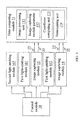
- the optical touch system of the present invention includes a control module 10; a data computing module 11; a plurality of image capturing modules 12, 14; a plurality of optical reflectors 181, 182, 183; a plurality of first light-emitting modules 161, 162; and a second light-emitting module 163.
- the control module 10 and the data computing module 11 are shown only in Fig. 3
- the optical reflectors 181 ⁇ 183 are shown only in Figs. 1 and 2 .
- the optical touch system is provided on a display screen 21, and a surface of the display screen 21 is served as a coordinate detection zone.
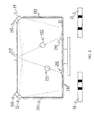
- the image capturing modules 12, 14 are arranged on an outer periphery of the display screen 21 at an upper left and an upper right corner thereof, respectively, when viewing in front of the display screen 21.
- the image capturing modules 12, 14 are so disposed on the places where the capturing module 12, 14 may capture any image on the surface of the display screen 21.
- the optical reflectors 181 ⁇ 183 are arranged at two lateral edges and a bottom edge of the display screen 21.
- the optical reflector 181 ⁇ 183 are made of a single-spectrum light-transmittable material, a light-mixing material, and a light-reflecting material.
- the first light-emitting modules 161, 162 are disposed at positions corresponding to the image acquiring modules 12, 14, such that light emitted from the first light-emitting modules 161, 162 is reflected by the optical reflectors 181 ⁇ 183 to thereby project to the image capturing modules 12, 14.
- the second light-emitting module 163 is arranged at an upper edge of the display screen 21 to locate between the image capturing modules 12 and 14.
- the first light-emitting modules 161, 162 or the second light-emitting module 163 emits an invisible light, such as an infrared ray; and the image capturing modules 12, 14 are able to capture invisible light images, such as infrared images.
- the first light-emitting modules 161, 162 are controlled by the control module 10 to emit light at a first time point.
- the image capturing modules 12, 14 are able to capture images that have different brightness from the background.
- the object would block optical paths of lights emitted from the first light-emitting modules 161, 162 to the optical reflectors 181 ⁇ 183, and the image capturing modules 12, 14 would capture dark areas formed by the object in the first images 13, 15.
- the display screen 21 is touched by two objects so that two touch positions 191, 192 are produced on the display screen 21, there are two dark areas shown in the content of each of the first images 13, 15.
- the data computing module 11 further includes an image processing unit 111, a set of image capturing module parameters 112, a coordinate computing unit 113, and a determining unit 114.
- the image processing unit 111 first analyzes the positions of the dark areas in the first images 13, 15.
- the image capturing module parameters 112 include at least a view angle parameter of the image capturing modules 12, 14, and the position and resolution of the image capturing modules on the coordinate detection zone. Since the first images 13, 15 are optical signals which are able to be received by the image capturing module 12, 14 respectively within a view angle 121; it is able to derive the positions of the objects blocking the optical paths relative to the image capturing modules 12, 14 based on the positions of the dark areas in the first images 13, 15.
- the coordinate computing unit 113 Since the dark areas are formed when the optical paths are blocked by the objects, the coordinate computing unit 113 is able to compute the rays projected to the objects blocking the optical paths based on the positions of the dark areas and the image capturing module parameters 112. That is, the coordinate computing unit 113 is able to determine on which rays the objects are located. Since the same one object will produce a dark area on each of the first images captured by different image capturing modules 12, 14, the coordinate computing unit 113 may obtain the coordinates of the object by calculating an intersection of the rays projected from the image capturing modules 12, 14 to the object. Since the above-described way of computing the coordinates of the object is the triangulation algorithm known by one having ordinary skill in the art, it is not described in details herein.
- the data computing module 11 computes two rays that are projected from each of the image capturing modules 12 and 14 respectively, and then, the data computing module 11 computes intersections of the four rays. However, there are four intersections 191 ⁇ 194 among the four rays. And accordingly, there are two object coordinates sets.
- the ray intersections 191, 192 provide the first object coordinates set; and the ray intersections 193, 194 provide the second object coordinates set.
- the second light-emitting module 163 is controlled by the control module 10 to emit light at a second time point and the first light-emitting modules 161, 162 is also controlled by the control module to stop emitting light at the same time. Then, the control module 10 controls the image capturing modules 12 or the image capturing module 14 to capture a second image 23 or 25. Please refer to Fig. 2 .
- the control module 10 controls the image capturing modules 12 or the image capturing module 14 to capture a second image 23 or 25.
- Fig. 2 When only the second light-emitting module 163 is controlled to emit light, two shadows of the two objects are formed on the optical reflector 182 at positions 291, 292 as indicated in Fig. 2 . Therefore, there are two dark areas in the second images 23 or 25 captured by the image capturing modules 12 or 14 respectively.
- the determining unit 114 of the data computing module 11 is able to determine which of the two object coordinates sets is to be selected according to the positions of the dark areas in any one of the second image 23, 25. Please refer to Figs. 1 and 2 at the same time. Suppose that the ray intersections 193, 194 are the touch positions, then the two shadows on the optical reflector 182 should be relatively close to each other in position, which is, however, not consistent with the positions of the dark areas in the second images 23 or 25. Therefore, the data computing module 11 determines the object coordinates set at the ray intersections 191, 192 as the correct touch positions.
- the image processing unit 111, the coordinate computing unit 113, and the determining unit 114 are preferably implemented in the form of software, such as related programs executed by a processor.
- optical touch system of the present invention employs the architecture of a conventional dual-image acquiring module, it further adds the second light-emitting module 162 and the determining unit 114 of the data computing module 11 to the conventional architecture, so that the optical touch system of the present invention provides increased accuracy of touch position determination for multi-touch devices.
- Fig. 4 is a flowchart showing the steps included in an optical touch method according to the present invention.
- a first step 41 at least one optical reflector, a plurality of image acquiring modules, a plurality of first light-emitting modules, and a second light-emitting module are provided on an outer periphery of a coordinate detection zone.
- the coordinate detection zone is a surface of a display screen, and the image capturing modules are separately arranged at two adjacent corners of the display screen, such as an upper left and an upper right corner.
- the at least one optical reflector is arranged at one edge of the display screen.
- three optical reflectors may be arranged at two lateral edges and a bottom edge of the display screen.
- the optical reflector is selected from the group consisting of a single-spectrum light-transmittable material, a light-mixing material, and a light-reflecting material.
- an integrally formed optical reflector is provided to cover the two lateral edges and the bottom edge of the display screen.
- the first light-emitting modules and the second light-emitting module are preferably provided to emit invisible light, such as infrared rays, and the image capturing modules are able to capture images, such as invisible light images, formed on the coordinate detection zone due to touch by the at least one object.
- a second step 42 the first light-emitting modules are controlled to emit light at a first time point, and the image capturing modules are controlled to capture a first image respectively at the first time point. Meanwhile, the second light-emitting module is controlled to stop emitting light at the first time point, so as to avoid any adverse influence on the number and the positions of dark areas formed in the first images.
- the second light-emitting module is controlled to emit light at a second time point and at least one of the image capturing modules is controlled to capture at least one second image at the second time point. Meanwhile, the first light-emitting modules are controlled to stop emitting light at the second time point, so as to avoid any adverse influence on the number and the positions of dark areas formed in the at least one second image.
- a fourth step 44 at least one object coordinates candidate set is computed based on the positions of dark areas formed by the at least one object in the first images.
- the positions of the dark areas formed by the at least one object in the first images are obtained through an image processing conducted on the first images.
- a fifth step 45 it is determined whether there is more than one object coordinates candidate set. If yes, a sixth step 46 is executed; or if no, a seventh step 47 is executed. In the seventh step 47, the object coordinates candidate set is output as the coordinates of the object.
- the sixth step 46 When there is more than one object coordinates candidate set, in the sixth step 46, according to the positions of the dark areas formed by the objects in the at least one second images, one of the multiple object coordinates candidate sets is determined as the coordinates of the objects. And then, the determined coordinates of the objects are output.
- the first time point and the second time point mentioned in the second step 42 and the third step 43 are intended only to explain that the first images and the at least one second image are captured at different time points, and not to limit the sequential order of acquiring the first and the second images.
- the step 43 can be otherwise executed first and the step 42 may be executed after the step 43.
Abstract
Description
- The present invention relates to an optical touch system and method, and more particularly to an optical touch technology for controlling a plurality of light sources to emit light at different time points, and computing spatial coordinates of specific objects that are shown in captured images at the different time points.
- With the constant progress of image display technology, the touch screen now advantageously allows a user to input data simply by touching the screen directly, and accordingly, becomes a widely available display device in the market. The touch screen is also widely applied to various kinds of electronic products, such as point of sale terminals, tourist guide systems, auto teller machines, and various industrial control systems. However, a touch screen employing optical lens detection technique would require a relatively large space to satisfy the requirement for screen touch detection because of the relatively large size of the conventional control mechanism thereof. With the conventional touch screen based on touch detection via optical lens, at least two image capturing modules are mounted on the display panel, and a plurality of infrared light sources is mounted on an outer periphery of the display panel, so that the image capturing modules capture infrared images above the surface of the display panel. When an object touches the surface of the display panel, the object would block the optical path via which the infrared rays emitted from the infrared light sources are projected to an optical reflector around the display panel. As a result, dark areas are produced on the optical reflector and captured by the image capturing modules. Then, by way of triangulation algorithm, virtual rays projected from the image acquiring modules to the touching object may be simulated. And, an intersection of the virtual rays indicates the position being touched by the object. Therefore, coordinates of the touch position may be computed in the above described manner.
- However, when the surface of the display panel is touched by a plurality of objects, a plurality of virtual rays may be simulated from each of the image capturing modules. Under this condition, the number of intersections of the virtual rays is larger than the number of the objects, and it will be difficult to accurately determine the exact touch positions to often result in wrong touch position determination. For example, when there are two touch positions on the display panel, total four dark areas produced on the optical reflector may be simulated from two rays projected from each of two image capturing modules to the optical reflector. Therefore, there would be four ray intersections, and accordingly, two possible sets of touch positions. In other words, the possibility of wrong touch position determination is 50% under this situation. With the popularization of touch devices, the demands for multi-touch screens also increase rapidly. It is therefore desirable to work out a way to increase the accuracy of touch position determination for multi-touch input.
- In view of the aforementioned problems of the prior art, a first object of the present invention is to provide an optical touch system that enables increased accuracy of touch position determination for multi-touch input.
- A second object of the present invention is to provide an optical touch method, with which touch positions on a multi-touch screen may be more accurately determined.
- To achieve the first object, the optical touch system according to a preferred embodiment of the present invention comprises at least one optical reflector, a plurality of image capturing modules, a plurality of first light-emitting modules, a second light-emitting module, a control module, and a data computing module. The at least one optical reflector, the image acquiring modules, the first light-emitting modules, and the second light-emitting module are disposed on an outer periphery of a coordinate detection zone. The image capturing modules capture images formed by at least one object on the coordinate detection zone. The control module controls the first light-emitting modules to emit light at a first time point, and controls the image capturing modules to capture a first image at the first time point respectively. The control module also controls the second light-emitting module to emit light at a second time point, and controls at least one of the image capturing modules to capture at least one second image at the second time point. The data computing module computes a coordinate value of the at least one object on the coordinate detection zone according to positions of the at least one object in each of the first images and the at least one second image.
- Preferably, the coordinate detection zone is a surface of a display screen.
- When the number of the at least one object is greater than one, the data computing module computes a plurality of object coordinates sets based on positions of the plurality of objects in each of the plurality of first images, and then determines one of the plurality of object coordinates sets as the coordinates of the plurality of objects based on positions of the plurality of objects in the at least one second image.
- Preferably, the data computing module computes a plurality of rays emitted from the plurality of image capturing modules based on the positions of the plurality of objects in each of the plurality of first images and positions of the plurality of image capturing modules on the coordinate detection zone, and the data computing module also computes coordinates of intersections among the plurality of rays and groups the coordinates of the intersections into the plurality of object coordinates candidate sets.
- Preferably, the control module controls the second light-emitting module to turn off while controlling the plurality of first light-emitting modules to emit light at the first time point. The control module also controls the plurality of first light-emitting modules to turn off while controlling the second light-emitting module to emit light at the second time point.
- To achieve the second object, the optical touch method according to the present invention comprises the following steps: (1) providing at least one optical reflector, a plurality of image capturing modules, a plurality of first light-emitting modules, and a second light-emitting module on an outer periphery of a coordinate detection zone; and using the plurality of image capturing modules to capture images formed by at least one object on the coordinate detection zone; (2) controlling the plurality of first light-emitting modules to emit light at a first time point, and controlling the plurality of image capturing modules to capture a first image at the first time point respectively; (3) controlling the second light-emitting module to emit light at a second time point, and controlling at least one of the plurality of image capturing modules to capture at least one second image at the second time point; and (4) computing coordinates of the at least one object on the coordinate detection zone based on positions of the at least one object in each of the plurality of first images and the at least one second image.
- Preferably, the coordinate detection zone is a surface of a display screen.
- When the number of the at least one object is greater than one, the optical touch method further comprises the following steps: computing a plurality of object coordinates sets based on positions of the plurality of objects in each of the plurality of first images, and then determining one of the plurality of object coordinates sets as the coordinates of the plurality of objects based on positions of the plurality of objects in the at least one second image.
- Preferably, the optical touch method further comprises the following steps: computing a plurality of rays emitted from the plurality of image capturing modules based on the positions of the plurality of objects in each of the plurality of first images and positions of the plurality of image capturing modules on the coordinate detection zone; computing coordinates of intersections among the plurality of rays; and grouping the coordinates of the intersections into the plurality of object coordinates candidate sets.
- Preferably, the optical touch method further comprises the step of controlling the second light-emitting module to turn off while controlling the plurality of first light-emitting modules to emit light at the first time point; and controlling the plurality of first light-emitting modules to turn off while controlling the second light-emitting module to emit light at the second time point.
- With the above arrangements, the optical touch system and method according to the present invention provide the advantage of increased accuracy of touch position determination for multi-touch input.
- The structure and the technical means adopted by the present invention to achieve the above and other objects can be best understood by referring to the following detailed description of the preferred embodiments and the accompanying drawings, wherein
-
Fig. 1 is a first schematic view of an optical touch system according to a preferred embodiment of the present invention; -
Fig. 2 is a second schematic view of the optical touch system according to the preferred embodiment of the present invention; -
Fig. 3 is a block diagram of the optical touch system according to the preferred embodiment of the present invention; and -
Fig. 4 is a flowchart showing the steps included in an optical touch method according to the present invention. - Please refer to
Figs. 1 and2 that are first and second schematic views, respectively, of an optical touch system according to a preferred embodiment; and toFig. 3 that is a block diagram of the optical touch system according to the preferred embodiment of the present invention. As shown, the optical touch system of the present invention includes acontrol module 10; adata computing module 11; a plurality ofimage capturing modules optical reflectors emitting modules emitting module 163. It is noted thecontrol module 10 and thedata computing module 11 are shown only inFig. 3 , and theoptical reflectors 181∼183 are shown only inFigs. 1 and2 . In the illustrated embodiment, the optical touch system is provided on adisplay screen 21, and a surface of thedisplay screen 21 is served as a coordinate detection zone. Theimage capturing modules display screen 21 at an upper left and an upper right corner thereof, respectively, when viewing in front of thedisplay screen 21. Theimage capturing modules module display screen 21. Theoptical reflectors 181∼183 are arranged at two lateral edges and a bottom edge of thedisplay screen 21. Preferably, theoptical reflector 181∼183 are made of a single-spectrum light-transmittable material, a light-mixing material, and a light-reflecting material. The first light-emitting modules image acquiring modules emitting modules optical reflectors 181∼183 to thereby project to theimage capturing modules emitting module 163 is arranged at an upper edge of thedisplay screen 21 to locate between theimage capturing modules emitting modules emitting module 163 emits an invisible light, such as an infrared ray; and theimage capturing modules - The first light-
emitting modules control module 10 to emit light at a first time point. At this point, theimage capturing modules display screen 21 is touched by an object, the object would block optical paths of lights emitted from the first light-emitting modules optical reflectors 181∼183, and theimage capturing modules first images display screen 21 is touched by two objects so that twotouch positions display screen 21, there are two dark areas shown in the content of each of thefirst images - The
data computing module 11 further includes animage processing unit 111, a set of imagecapturing module parameters 112, acoordinate computing unit 113, and a determiningunit 114. When thefirst image data computing module 11, theimage processing unit 111 first analyzes the positions of the dark areas in thefirst images module parameters 112 include at least a view angle parameter of theimage capturing modules first images image capturing module view angle 121; it is able to derive the positions of the objects blocking the optical paths relative to theimage capturing modules first images computing unit 113 is able to compute the rays projected to the objects blocking the optical paths based on the positions of the dark areas and the imagecapturing module parameters 112. That is, the coordinatecomputing unit 113 is able to determine on which rays the objects are located. Since the same one object will produce a dark area on each of the first images captured by differentimage capturing modules computing unit 113 may obtain the coordinates of the object by calculating an intersection of the rays projected from theimage capturing modules - When the
display screen 21 is touched by a plurality of objects at the same time, such as two objects as shown inFig. 1 , there are two dark areas formed in thefirst images data computing module 11 computes two rays that are projected from each of theimage capturing modules data computing module 11 computes intersections of the four rays. However, there are fourintersections 191∼194 among the four rays. And accordingly, there are two object coordinates sets. Theray intersections ray intersections module 163 is controlled by thecontrol module 10 to emit light at a second time point and the first light-emittingmodules control module 10 controls theimage capturing modules 12 or theimage capturing module 14 to capture asecond image Fig. 2 . When only the second light-emittingmodule 163 is controlled to emit light, two shadows of the two objects are formed on theoptical reflector 182 atpositions Fig. 2 . Therefore, there are two dark areas in thesecond images image capturing modules - The determining
unit 114 of thedata computing module 11 is able to determine which of the two object coordinates sets is to be selected according to the positions of the dark areas in any one of thesecond image Figs. 1 and2 at the same time. Suppose that theray intersections optical reflector 182 should be relatively close to each other in position, which is, however, not consistent with the positions of the dark areas in thesecond images data computing module 11 determines the object coordinates set at theray intersections image processing unit 111, the coordinatecomputing unit 113, and the determiningunit 114 are preferably implemented in the form of software, such as related programs executed by a processor. - While the optical touch system of the present invention employs the architecture of a conventional dual-image acquiring module, it further adds the second light-emitting
module 162 and the determiningunit 114 of thedata computing module 11 to the conventional architecture, so that the optical touch system of the present invention provides increased accuracy of touch position determination for multi-touch devices. - Please refer to
Fig. 4 , which is a flowchart showing the steps included in an optical touch method according to the present invention. As shown, in afirst step 41, at least one optical reflector, a plurality of image acquiring modules, a plurality of first light-emitting modules, and a second light-emitting module are provided on an outer periphery of a coordinate detection zone. Preferably, the coordinate detection zone is a surface of a display screen, and the image capturing modules are separately arranged at two adjacent corners of the display screen, such as an upper left and an upper right corner. The at least one optical reflector is arranged at one edge of the display screen. For example, three optical reflectors may be arranged at two lateral edges and a bottom edge of the display screen. Preferably, the optical reflector is selected from the group consisting of a single-spectrum light-transmittable material, a light-mixing material, and a light-reflecting material. Alternatively, an integrally formed optical reflector is provided to cover the two lateral edges and the bottom edge of the display screen. And, the first light-emitting modules and the second light-emitting module are preferably provided to emit invisible light, such as infrared rays, and the image capturing modules are able to capture images, such as invisible light images, formed on the coordinate detection zone due to touch by the at least one object. - In a
second step 42, the first light-emitting modules are controlled to emit light at a first time point, and the image capturing modules are controlled to capture a first image respectively at the first time point. Meanwhile, the second light-emitting module is controlled to stop emitting light at the first time point, so as to avoid any adverse influence on the number and the positions of dark areas formed in the first images. In athird step 43, the second light-emitting module is controlled to emit light at a second time point and at least one of the image capturing modules is controlled to capture at least one second image at the second time point. Meanwhile, the first light-emitting modules are controlled to stop emitting light at the second time point, so as to avoid any adverse influence on the number and the positions of dark areas formed in the at least one second image. - In a
fourth step 44, at least one object coordinates candidate set is computed based on the positions of dark areas formed by the at least one object in the first images. In the present invention, the positions of the dark areas formed by the at least one object in the first images are obtained through an image processing conducted on the first images. In afifth step 45, it is determined whether there is more than one object coordinates candidate set. If yes, asixth step 46 is executed; or if no, aseventh step 47 is executed. In theseventh step 47, the object coordinates candidate set is output as the coordinates of the object. - When there is more than one object coordinates candidate set, in the
sixth step 46, according to the positions of the dark areas formed by the objects in the at least one second images, one of the multiple object coordinates candidate sets is determined as the coordinates of the objects. And then, the determined coordinates of the objects are output. It is noted the first time point and the second time point mentioned in thesecond step 42 and thethird step 43 are intended only to explain that the first images and the at least one second image are captured at different time points, and not to limit the sequential order of acquiring the first and the second images. In other words, thestep 43 can be otherwise executed first and thestep 42 may be executed after thestep 43. - The present invention has been described with some preferred embodiments thereof and it is understood that many changes and modifications in the described embodiments can be carried out without departing from the scope and the spirit of the invention that is intended to be limited only by the appended claims.
Claims (14)
- An optical touch system, comprising:a plurality of first light-emitting modules (161,162) being disposed on an outer periphery of a coordinate detection zone;a second light-emitting module (163) being disposed on the outer periphery of the coordinate detection zone;a plurality of image capturing modules (12,14) being arranged for capturing images formed by at least one object on the coordinate detection zone;at least one optical reflector (181,182,183) being disposed on the outer periphery of the coordinate detection zone for reflecting light emitted from the plurality of first light-emitting modules (161,162) and the second light-emitting module (163) to the plurality of image capturing modules (12,14);a control module (10) being arranged for controlling the plurality of first light-emitting modules (161,162) to emit light at a first time point, and controlling the plurality of image capturing modules (12,14) to capture a first image (13,15) at the first time point respectively, and the control module (10) being arranged for controlling the second light-emitting module (163) to emit light at a second time point, and controlling at least one of the plurality of image capturing modules (12 or 14) to capture at least one second image (23 or 25) at the second time point respectively; anda data computing module (11) be arranged for computing coordinate of the at least one object on the coordinate detection zone according to positions of the at least one object in each of the plurality of first images (13,15) and in the at least one second image (23 or 25).
- The optical touch system as claimed in claim 1, wherein the coordinate detection zone is a surface of a display screen (21), and the at least one optical reflector being disposed on edges of the display screen (21), and the plurality of image capturing modules (12,14) be disposed at corners of the display screen (21) respectively.
- The optical touch system as claimed in claim 2, wherein the second light-emitting module (163) is disposed on the edge of the display screen (21) and between the plurality of image capturing modules (12,14).
- The optical touch system as claimed in claim 1, wherein, when the number of the at least one object is greater than one, the data computing module (11) computing a plurality of object coordinates candidate sets based on the positions of the plurality of objects in each of the plurality of first images (13,15), and then determining one of the plurality of object coordinate candidate sets as the coordinates of the plurality of objects based on the positions of the plurality of objects in the at least one second image (23 or 25).
- The optical touch system as claimed in claim 4, wherein the data computing module (11) computes a plurality of rays emitted from the plurality image capturing modules (12,14) based on the positions of the plurality of objects in each of the plurality of first images (13,15) and the positions of the plurality of image capturing modules (12,14) on the coordinate detection zone, and computing coordinates of intersections (191,192,193,194) among the plurality of the rays and grouping the coordinates of the intersections (191,192,193,194) into the plurality of object coordinates sets.
- The optical touch system as claimed in claim 1, wherein the control module controls the second light-emitting module to turn off while controlling the plurality of first light-emitting modules to emit light at the first time point.
- The optical touch system as claimed in claim 1, wherein the control module (10) controls the plurality of first light-emitting modules (161,162) to turn off while controlling the second light-emitting module (163) to emit light at the second time point.
- An optical touch method, comprising the following steps of:providing at least one optical reflector (181,182,183), a plurality of image capturing modules (12,14), a plurality of first light-emitting modules (161,162), and a second light-emitting module (163) on an outer periphery of a coordinate detection zone, and the plurality of image capturing modules being arranged for capturing images formed by at least one object on the coordinate detection zone;controlling the plurality of first light-emitting modules to emit light at a first time point, and controlling the plurality of image capturing modules to capture a first image each at the first time point respectively;controlling the second light-emitting module (163) to emit light at a second time point, and controlling at least one of the plurality of the image capturing modules (12 or 14) to capture at least one second image (23 or 25) at the second time point; andcomputing a coordinate value of the at least one object on the coordinate detection zone based on positions of the at least one object in each of the plurality of first images (13,15) and in the at least one second image (23 or 25).
- The optical touch method as claimed in claim 8, wherein the coordinate detection zone is a surface of a display screen (21), and the at least one optical reflector (181,182,183) being disposed on edges of the display screen (21), and the plurality of image capturing modules (12,14) being disposed at corners of the display screen (21) respectively.
- The optical touch method as claimed in claim 9, wherein the second light-emitting module (163) is disposed on the edge of the display screen (21) and between the plurality of image capturing modules (161,162).
- The optical touch method as claimed in claim 8, further comprising the following steps of when the number of the at least one object is greater than one:computing a plurality of object coordinates candidate sets based on the positions of the plurality of objects in each of the plurality of first images (13,15); anddetermining one of the plurality of object coordinates candidate sets as coordinates of the plurality of objects according to the positions of the plurality objects in the at least one second image (23 or 25).
- The optical touch method as claimed in claim 11, further comprising the following steps of:computing a plurality of rays emitted from the plurality of image capturing modules (12,14) based on the positions of the plurality of objects in each of the plurality of first images (13,15) and the positions of the plurality of image capturing modules (12,14) on the coordinate detection zone;computing coordinates of intersections (191,192,193,194) among the plurality of rays; andgrouping the coordinates of the intersections (191,192,193,194) into the plurality of object coordinates sets.
- The optical touch method as claimed in claim 8, further comprising the step of:controlling the second light-emitting module (163) to turn off while controlling the plurality of first light-emitting modules (161,162) to emit light at the first time point.
- The optical touch method as claimed in claim 8, further comprising the step of:controlling the plurality of first light-emitting modules (161,162) to turn off while controlling the second light-emitting module (163) to emit light at the second time point.
Applications Claiming Priority (2)
| Application Number | Priority Date | Filing Date | Title |
|---|---|---|---|
| TW98132362 | 2009-09-24 | ||
| TW098139011A TWI410841B (en) | 2009-09-24 | 2009-11-17 | Optical touch system and its method |
Publications (2)
| Publication Number | Publication Date |
|---|---|
| EP2302491A2 true EP2302491A2 (en) | 2011-03-30 |
| EP2302491A3 EP2302491A3 (en) | 2014-07-02 |
Family
ID=43216554
Family Applications (1)
| Application Number | Title | Priority Date | Filing Date |
|---|---|---|---|
| EP10152886.7A Withdrawn EP2302491A3 (en) | 2009-09-24 | 2010-02-08 | Optical touch system and method |
Country Status (5)
| Country | Link |
|---|---|
| US (1) | US20110069037A1 (en) |
| EP (1) | EP2302491A3 (en) |
| JP (1) | JP5308359B2 (en) |
| KR (1) | KR101123932B1 (en) |
| TW (1) | TWI410841B (en) |
Families Citing this family (15)
| Publication number | Priority date | Publication date | Assignee | Title |
|---|---|---|---|---|
| US9557837B2 (en) | 2010-06-15 | 2017-01-31 | Pixart Imaging Inc. | Touch input apparatus and operation method thereof |
| TWI450154B (en) * | 2010-09-29 | 2014-08-21 | Pixart Imaging Inc | Optical touch system and object detection method therefor |
| TWI490756B (en) * | 2013-01-09 | 2015-07-01 | 原相科技股份有限公司 | Optical touch system |
| TWI441060B (en) | 2011-04-14 | 2014-06-11 | Pixart Imaging Inc | Image processing method for optical touch system |
| TWI454995B (en) * | 2011-08-11 | 2014-10-01 | Wistron Corp | Optical touch device and coordinate detection method thereof |
| TWI460636B (en) * | 2011-09-07 | 2014-11-11 | Pixart Imaging Inc | Optical touch panel system and positioning method thereof |
| TWI471785B (en) | 2011-09-15 | 2015-02-01 | Wintek Corp | Optical touch module |
| TWI475446B (en) * | 2012-04-24 | 2015-03-01 | Wistron Corp | Optical touch control system and capture signal adjusting method thereof |
| TWI470512B (en) * | 2012-07-13 | 2015-01-21 | Wistron Corp | Optical touch method and system thereof |
| TWI489352B (en) * | 2013-08-13 | 2015-06-21 | Wistron Corp | Optical touch positioning method, system and optical touch positioner |
| TWI498793B (en) * | 2013-09-18 | 2015-09-01 | Wistron Corp | Optical touch system and control method |
| TWI533179B (en) | 2013-10-25 | 2016-05-11 | 緯創資通股份有限公司 | Optical touch system, method of touch detection, and computer program product |
| TWI515622B (en) * | 2013-11-14 | 2016-01-01 | 緯創資通股份有限公司 | Method for optically detecting location and device for optically detecting location |
| TWI553531B (en) * | 2013-11-29 | 2016-10-11 | 緯創資通股份有限公司 | Optical touch device and method for calculating coordinate of touch point |
| CN104808868B (en) * | 2015-05-28 | 2017-09-12 | 成都吉锐触摸技术股份有限公司 | A kind of method that surface acoustic wave touch screen realizes multiple point touching |
Family Cites Families (16)
| Publication number | Priority date | Publication date | Assignee | Title |
|---|---|---|---|---|
| JP3946936B2 (en) | 2000-06-26 | 2007-07-18 | 株式会社シロク | Optical digitizer |
| JP2003303046A (en) * | 2002-04-11 | 2003-10-24 | Ricoh Elemex Corp | Optical coordinate detection device |
| JP4118664B2 (en) * | 2002-12-06 | 2008-07-16 | リコーエレメックス株式会社 | Coordinate detection device |
| US7042444B2 (en) * | 2003-01-17 | 2006-05-09 | Eastman Kodak Company | OLED display and touch screen |
| JP2005107607A (en) * | 2003-09-29 | 2005-04-21 | Eit:Kk | Optical position detecting apparatus |
| US7232986B2 (en) | 2004-02-17 | 2007-06-19 | Smart Technologies Inc. | Apparatus for detecting a pointer within a region of interest |
| US7460110B2 (en) * | 2004-04-29 | 2008-12-02 | Smart Technologies Ulc | Dual mode touch system |
| JP4442877B2 (en) * | 2004-07-14 | 2010-03-31 | キヤノン株式会社 | Coordinate input device and control method thereof |
| JP4592085B2 (en) * | 2005-05-06 | 2010-12-01 | キヤノン株式会社 | Information processing apparatus, control method therefor, and program |
| TWI339808B (en) * | 2007-09-07 | 2011-04-01 | Quanta Comp Inc | Method and system for distinguishing multiple touch points |
| KR20090026957A (en) * | 2007-09-11 | 2009-03-16 | 엘지디스플레이 주식회사 | Image display device including touch panel |
| TWI382337B (en) * | 2007-11-30 | 2013-01-11 | Univ Lunghwa Sci & Technology | Touch screen system with light reflection |
| TWI382502B (en) * | 2007-12-02 | 2013-01-11 | Univ Lunghwa Sci & Technology | Chip package |
| TWI403926B (en) * | 2007-12-28 | 2013-08-01 | Ibm | Optical touch panel |
| US20090219256A1 (en) * | 2008-02-11 | 2009-09-03 | John David Newton | Systems and Methods for Resolving Multitouch Scenarios for Optical Touchscreens |
| KR100910024B1 (en) | 2008-10-13 | 2009-07-30 | 호감테크놀로지(주) | Camera type touch-screen utilizing linear infrared emitter |
-
2009
- 2009-11-17 TW TW098139011A patent/TWI410841B/en not_active IP Right Cessation
-
2010
- 2010-01-15 JP JP2010007198A patent/JP5308359B2/en active Active
- 2010-01-22 US US12/691,751 patent/US20110069037A1/en not_active Abandoned
- 2010-02-08 EP EP10152886.7A patent/EP2302491A3/en not_active Withdrawn
- 2010-02-19 KR KR1020100015242A patent/KR101123932B1/en active IP Right Grant
Non-Patent Citations (1)
| Title |
|---|
| None |
Also Published As
| Publication number | Publication date |
|---|---|
| TWI410841B (en) | 2013-10-01 |
| KR20110032995A (en) | 2011-03-30 |
| JP5308359B2 (en) | 2013-10-09 |
| JP2011070625A (en) | 2011-04-07 |
| KR101123932B1 (en) | 2012-03-23 |
| EP2302491A3 (en) | 2014-07-02 |
| US20110069037A1 (en) | 2011-03-24 |
| TW201112092A (en) | 2011-04-01 |
Similar Documents
| Publication | Publication Date | Title |
|---|---|---|
| EP2302491A2 (en) | Optical touch system and method | |
| EP2353069B1 (en) | Stereo optical sensors for resolving multi-touch in a touch detection system | |
| US20110261016A1 (en) | Optical touch screen system and method for recognizing a relative distance of objects | |
| US8922526B2 (en) | Touch detection apparatus and touch point detection method | |
| KR20100055516A (en) | Optical touchscreen with improved illumination | |
| US20110199335A1 (en) | Determining a Position of an Object Using a Single Camera | |
| US20100045629A1 (en) | Systems For Resolving Touch Points for Optical Touchscreens | |
| US20150253934A1 (en) | Object detection method and calibration apparatus of optical touch system | |
| US8599171B2 (en) | Optical position detecting device and display device with position detecting function | |
| US20150253933A1 (en) | Optical touch apparatus and optical touch method | |
| JP2005107607A (en) | Optical position detecting apparatus | |
| TWI534687B (en) | Optical touch detection system and object analyzation method thereof | |
| WO2013035553A1 (en) | User interface display device | |
| US9471180B2 (en) | Optical touch panel system, optical apparatus and positioning method thereof | |
| US20110096031A1 (en) | Position detecting function-added projection display apparatus | |
| US20160092032A1 (en) | Optical touch screen system and computing method thereof | |
| US20100295823A1 (en) | Apparatus for touching reflection image using an infrared screen | |
| US20140131550A1 (en) | Optical touch device and touch control method thereof | |
| US20130016069A1 (en) | Optical imaging device and imaging processing method for optical imaging device | |
| CN102043543B (en) | Optical touch control system and method | |
| US9323394B2 (en) | Touch control apparatus and associated selection method | |
| US8912482B2 (en) | Position determining device and method for objects on a touch device having a stripped L-shaped reflecting mirror and a stripped retroreflector | |
| KR20170021665A (en) | Display apparatus with optical touch screen function | |
| CN102364418B (en) | Optical touch-control positioning system and method | |
| KR101118640B1 (en) | The touch-screen using infrared camera |
Legal Events
| Date | Code | Title | Description |
|---|---|---|---|
| PUAI | Public reference made under article 153(3) epc to a published international application that has entered the european phase |
Free format text: ORIGINAL CODE: 0009012 |
|
| AK | Designated contracting states |
Kind code of ref document: A2 Designated state(s): AT BE BG CH CY CZ DE DK EE ES FI FR GB GR HR HU IE IS IT LI LT LU LV MC MK MT NL NO PL PT RO SE SI SK SM TR |
|
| AX | Request for extension of the european patent |
Extension state: AL BA RS |
|
| PUAL | Search report despatched |
Free format text: ORIGINAL CODE: 0009013 |
|
| AK | Designated contracting states |
Kind code of ref document: A3 Designated state(s): AT BE BG CH CY CZ DE DK EE ES FI FR GB GR HR HU IE IS IT LI LT LU LV MC MK MT NL NO PL PT RO SE SI SK SM TR |
|
| AX | Request for extension of the european patent |
Extension state: AL BA RS |
|
| RIC1 | Information provided on ipc code assigned before grant |
Ipc: G06F 3/041 20060101ALI20140523BHEP Ipc: G06F 3/042 20060101AFI20140523BHEP |
|
| STAA | Information on the status of an ep patent application or granted ep patent |
Free format text: STATUS: THE APPLICATION IS DEEMED TO BE WITHDRAWN |
|
| 18D | Application deemed to be withdrawn |
Effective date: 20150106 |