EP2302761A1 - Powerline control system - Google Patents
Powerline control system Download PDFInfo
- Publication number
- EP2302761A1 EP2302761A1 EP10183876A EP10183876A EP2302761A1 EP 2302761 A1 EP2302761 A1 EP 2302761A1 EP 10183876 A EP10183876 A EP 10183876A EP 10183876 A EP10183876 A EP 10183876A EP 2302761 A1 EP2302761 A1 EP 2302761A1
- Authority
- EP
- European Patent Office
- Prior art keywords
- luminaire
- telegram
- information
- lights
- lamp
- Prior art date
- Legal status (The legal status is an assumption and is not a legal conclusion. Google has not performed a legal analysis and makes no representation as to the accuracy of the status listed.)
- Granted
Links
- 238000000034 method Methods 0.000 claims description 35
- 230000007613 environmental effect Effects 0.000 claims description 6
- 230000001360 synchronised effect Effects 0.000 abstract description 10
- 230000005540 biological transmission Effects 0.000 description 56
- 230000000875 corresponding effect Effects 0.000 description 17
- 238000004891 communication Methods 0.000 description 12
- 230000006870 function Effects 0.000 description 12
- 230000009471 action Effects 0.000 description 5
- 230000001276 controlling effect Effects 0.000 description 4
- 238000005259 measurement Methods 0.000 description 3
- 230000007246 mechanism Effects 0.000 description 3
- 238000012544 monitoring process Methods 0.000 description 3
- 230000004044 response Effects 0.000 description 3
- 238000012546 transfer Methods 0.000 description 3
- 230000008859 change Effects 0.000 description 2
- 238000001514 detection method Methods 0.000 description 2
- 238000005516 engineering process Methods 0.000 description 2
- 238000012423 maintenance Methods 0.000 description 2
- 230000010363 phase shift Effects 0.000 description 2
- 230000008569 process Effects 0.000 description 2
- 238000010276 construction Methods 0.000 description 1
- 125000004122 cyclic group Chemical group 0.000 description 1
- 230000007547 defect Effects 0.000 description 1
- 238000011161 development Methods 0.000 description 1
- 238000010586 diagram Methods 0.000 description 1
- 230000004069 differentiation Effects 0.000 description 1
- 238000011156 evaluation Methods 0.000 description 1
- 238000005286 illumination Methods 0.000 description 1
- 230000006872 improvement Effects 0.000 description 1
- 238000009434 installation Methods 0.000 description 1
- 230000001629 suppression Effects 0.000 description 1
- 230000002123 temporal effect Effects 0.000 description 1
- 230000001960 triggered effect Effects 0.000 description 1
- 238000012795 verification Methods 0.000 description 1
Images


Classifications
-
- H—ELECTRICITY
- H04—ELECTRIC COMMUNICATION TECHNIQUE
- H04L—TRANSMISSION OF DIGITAL INFORMATION, e.g. TELEGRAPHIC COMMUNICATION
- H04L12/00—Data switching networks
- H04L12/02—Details
- H04L12/10—Current supply arrangements
-
- H—ELECTRICITY
- H04—ELECTRIC COMMUNICATION TECHNIQUE
- H04B—TRANSMISSION
- H04B3/00—Line transmission systems
- H04B3/54—Systems for transmission via power distribution lines
-
- H—ELECTRICITY
- H04—ELECTRIC COMMUNICATION TECHNIQUE
- H04B—TRANSMISSION
- H04B3/00—Line transmission systems
- H04B3/54—Systems for transmission via power distribution lines
- H04B3/546—Combination of signalling, telemetering, protection
-
- H—ELECTRICITY
- H04—ELECTRIC COMMUNICATION TECHNIQUE
- H04B—TRANSMISSION
- H04B3/00—Line transmission systems
- H04B3/54—Systems for transmission via power distribution lines
- H04B3/58—Repeater circuits
-
- H—ELECTRICITY
- H05—ELECTRIC TECHNIQUES NOT OTHERWISE PROVIDED FOR
- H05B—ELECTRIC HEATING; ELECTRIC LIGHT SOURCES NOT OTHERWISE PROVIDED FOR; CIRCUIT ARRANGEMENTS FOR ELECTRIC LIGHT SOURCES, IN GENERAL
- H05B47/00—Circuit arrangements for operating light sources in general, i.e. where the type of light source is not relevant
- H05B47/10—Controlling the light source
- H05B47/16—Controlling the light source by timing means
-
- H—ELECTRICITY
- H05—ELECTRIC TECHNIQUES NOT OTHERWISE PROVIDED FOR
- H05B—ELECTRIC HEATING; ELECTRIC LIGHT SOURCES NOT OTHERWISE PROVIDED FOR; CIRCUIT ARRANGEMENTS FOR ELECTRIC LIGHT SOURCES, IN GENERAL
- H05B47/00—Circuit arrangements for operating light sources in general, i.e. where the type of light source is not relevant
- H05B47/10—Controlling the light source
- H05B47/175—Controlling the light source by remote control
- H05B47/185—Controlling the light source by remote control via power line carrier transmission
-
- H—ELECTRICITY
- H05—ELECTRIC TECHNIQUES NOT OTHERWISE PROVIDED FOR
- H05B—ELECTRIC HEATING; ELECTRIC LIGHT SOURCES NOT OTHERWISE PROVIDED FOR; CIRCUIT ARRANGEMENTS FOR ELECTRIC LIGHT SOURCES, IN GENERAL
- H05B47/00—Circuit arrangements for operating light sources in general, i.e. where the type of light source is not relevant
- H05B47/20—Responsive to malfunctions or to light source life; for protection
- H05B47/21—Responsive to malfunctions or to light source life; for protection of two or more light sources connected in parallel
- H05B47/22—Responsive to malfunctions or to light source life; for protection of two or more light sources connected in parallel with communication between the lamps and a central unit
-
- H—ELECTRICITY
- H02—GENERATION; CONVERSION OR DISTRIBUTION OF ELECTRIC POWER
- H02J—CIRCUIT ARRANGEMENTS OR SYSTEMS FOR SUPPLYING OR DISTRIBUTING ELECTRIC POWER; SYSTEMS FOR STORING ELECTRIC ENERGY
- H02J13/00—Circuit arrangements for providing remote indication of network conditions, e.g. an instantaneous record of the open or closed condition of each circuitbreaker in the network; Circuit arrangements for providing remote control of switching means in a power distribution network, e.g. switching in and out of current consumers by using a pulse code signal carried by the network
- H02J13/00006—Circuit arrangements for providing remote indication of network conditions, e.g. an instantaneous record of the open or closed condition of each circuitbreaker in the network; Circuit arrangements for providing remote control of switching means in a power distribution network, e.g. switching in and out of current consumers by using a pulse code signal carried by the network characterised by information or instructions transport means between the monitoring, controlling or managing units and monitored, controlled or operated power network element or electrical equipment
- H02J13/00007—Circuit arrangements for providing remote indication of network conditions, e.g. an instantaneous record of the open or closed condition of each circuitbreaker in the network; Circuit arrangements for providing remote control of switching means in a power distribution network, e.g. switching in and out of current consumers by using a pulse code signal carried by the network characterised by information or instructions transport means between the monitoring, controlling or managing units and monitored, controlled or operated power network element or electrical equipment using the power network as support for the transmission
- H02J13/00009—Circuit arrangements for providing remote indication of network conditions, e.g. an instantaneous record of the open or closed condition of each circuitbreaker in the network; Circuit arrangements for providing remote control of switching means in a power distribution network, e.g. switching in and out of current consumers by using a pulse code signal carried by the network characterised by information or instructions transport means between the monitoring, controlling or managing units and monitored, controlled or operated power network element or electrical equipment using the power network as support for the transmission using pulsed signals
-
- H—ELECTRICITY
- H04—ELECTRIC COMMUNICATION TECHNIQUE
- H04B—TRANSMISSION
- H04B2203/00—Indexing scheme relating to line transmission systems
- H04B2203/54—Aspects of powerline communications not already covered by H04B3/54 and its subgroups
- H04B2203/5404—Methods of transmitting or receiving signals via power distribution lines
- H04B2203/5416—Methods of transmitting or receiving signals via power distribution lines by adding signals to the wave form of the power source
-
- H—ELECTRICITY
- H04—ELECTRIC COMMUNICATION TECHNIQUE
- H04B—TRANSMISSION
- H04B2203/00—Indexing scheme relating to line transmission systems
- H04B2203/54—Aspects of powerline communications not already covered by H04B3/54 and its subgroups
- H04B2203/5404—Methods of transmitting or receiving signals via power distribution lines
- H04B2203/542—Methods of transmitting or receiving signals via power distribution lines using zero crossing information
-
- H—ELECTRICITY
- H04—ELECTRIC COMMUNICATION TECHNIQUE
- H04B—TRANSMISSION
- H04B2203/00—Indexing scheme relating to line transmission systems
- H04B2203/54—Aspects of powerline communications not already covered by H04B3/54 and its subgroups
- H04B2203/5429—Applications for powerline communications
- H04B2203/5458—Monitor sensor; Alarm systems
-
- H—ELECTRICITY
- H04—ELECTRIC COMMUNICATION TECHNIQUE
- H04B—TRANSMISSION
- H04B2203/00—Indexing scheme relating to line transmission systems
- H04B2203/54—Aspects of powerline communications not already covered by H04B3/54 and its subgroups
- H04B2203/5462—Systems for power line communications
- H04B2203/5483—Systems for power line communications using coupling circuits
-
- Y—GENERAL TAGGING OF NEW TECHNOLOGICAL DEVELOPMENTS; GENERAL TAGGING OF CROSS-SECTIONAL TECHNOLOGIES SPANNING OVER SEVERAL SECTIONS OF THE IPC; TECHNICAL SUBJECTS COVERED BY FORMER USPC CROSS-REFERENCE ART COLLECTIONS [XRACs] AND DIGESTS
- Y02—TECHNOLOGIES OR APPLICATIONS FOR MITIGATION OR ADAPTATION AGAINST CLIMATE CHANGE
- Y02B—CLIMATE CHANGE MITIGATION TECHNOLOGIES RELATED TO BUILDINGS, e.g. HOUSING, HOUSE APPLIANCES OR RELATED END-USER APPLICATIONS
- Y02B20/00—Energy efficient lighting technologies, e.g. halogen lamps or gas discharge lamps
- Y02B20/40—Control techniques providing energy savings, e.g. smart controller or presence detection
-
- Y—GENERAL TAGGING OF NEW TECHNOLOGICAL DEVELOPMENTS; GENERAL TAGGING OF CROSS-SECTIONAL TECHNOLOGIES SPANNING OVER SEVERAL SECTIONS OF THE IPC; TECHNICAL SUBJECTS COVERED BY FORMER USPC CROSS-REFERENCE ART COLLECTIONS [XRACs] AND DIGESTS
- Y02—TECHNOLOGIES OR APPLICATIONS FOR MITIGATION OR ADAPTATION AGAINST CLIMATE CHANGE
- Y02B—CLIMATE CHANGE MITIGATION TECHNOLOGIES RELATED TO BUILDINGS, e.g. HOUSING, HOUSE APPLIANCES OR RELATED END-USER APPLICATIONS
- Y02B90/00—Enabling technologies or technologies with a potential or indirect contribution to GHG emissions mitigation
- Y02B90/20—Smart grids as enabling technology in buildings sector
-
- Y—GENERAL TAGGING OF NEW TECHNOLOGICAL DEVELOPMENTS; GENERAL TAGGING OF CROSS-SECTIONAL TECHNOLOGIES SPANNING OVER SEVERAL SECTIONS OF THE IPC; TECHNICAL SUBJECTS COVERED BY FORMER USPC CROSS-REFERENCE ART COLLECTIONS [XRACs] AND DIGESTS
- Y04—INFORMATION OR COMMUNICATION TECHNOLOGIES HAVING AN IMPACT ON OTHER TECHNOLOGY AREAS
- Y04S—SYSTEMS INTEGRATING TECHNOLOGIES RELATED TO POWER NETWORK OPERATION, COMMUNICATION OR INFORMATION TECHNOLOGIES FOR IMPROVING THE ELECTRICAL POWER GENERATION, TRANSMISSION, DISTRIBUTION, MANAGEMENT OR USAGE, i.e. SMART GRIDS
- Y04S40/00—Systems for electrical power generation, transmission, distribution or end-user application management characterised by the use of communication or information technologies, or communication or information technology specific aspects supporting them
- Y04S40/12—Systems for electrical power generation, transmission, distribution or end-user application management characterised by the use of communication or information technologies, or communication or information technology specific aspects supporting them characterised by data transport means between the monitoring, controlling or managing units and monitored, controlled or operated electrical equipment
- Y04S40/121—Systems for electrical power generation, transmission, distribution or end-user application management characterised by the use of communication or information technologies, or communication or information technology specific aspects supporting them characterised by data transport means between the monitoring, controlling or managing units and monitored, controlled or operated electrical equipment using the power network as support for the transmission
Definitions
- the present invention relates to a control system for electrical devices such as outdoor lighting systems or a method for operating outdoor lighting systems.
- the control devices for operating lamps which have been developed in recent years, have opened up the possibility of forming complex illumination systems in which the distributed luminaires are individually controlled by a central unit.
- Such lighting systems are used, for example, in larger buildings, the lights are usually connected to the one to the normal power supply network and connected to the other via a bus line to the central unit. Via this bus line, digital commands are transmitted from the central unit to the control units of the decentrally arranged lights.
- a corresponding structure would of course also in outdoor lighting systems - for example, for street lighting or the like - possible, but the difficulty then is to allow transmission of the control commands from the central unit to the far away lights.
- the laying of bus lines is usually difficult or even impossible in outdoor lighting systems because of the relatively large distances and the associated effort.
- Powerline technology An alternative possibility for data transmission without the need for additional bus lines is in the so-called.
- the power supply lines themselves are used for data transmission by modulating to the normal line frequency of 50 Hz higher frequency carrier frequency is applied.
- the carrier frequency contains in encrypted form the information to be transmitted, which are decrypted by corresponding receivers.
- Such power line methods are already used in some lighting systems for building lighting or other home-internal control systems, in which case the internal power network is used for data transmission.
- a versatile and trouble-free operation - for example, the lights - are made possible.
- a first aspect of the invention relates to a method for controlling electrical devices, in particular lights, which are connected to a common power supply network.
- the electrical devices exchange information with a control unit via the power supply network by means of a powerline method, with the electrical devices being synchronized with one another in such a way that they receive information from the power supply network or transmit it to the power supply network during predetermined transmission and reception cycles.
- each electrical device acts as a so-called.
- Repeater by it sends a received in a transmission and reception cycle information - hereinafter referred to as a telegram - in an indirectly or immediately following transmission and reception cycle back into the power grid.
- a telegram fed in at any desired point into the power supply network spreads, as it were, like an avalanche over the entire network until finally it is received by the addressed electrical device.
- an electrical device only forwards a telegram if this telegram is not exclusively intended for the respective electrical device itself.
- the method according to the invention is characterized in particular by the fact that in this way a high data throughput with a low error rate is achieved in a simple manner.
- the electrical devices send information to be forwarded to the power supply network for a predetermined number of successive transmission and reception cycles. This increases the transmission reliability.
- the electrical equipment are able to recognize once received and forwarded telegrams so that they one at a later time once again received telegram no longer forward. This prevents telegrams from running in endless loops through the network. This recognition can be made possible for example by a suitable indexing (index number etc.) of the telegrams.
- the data transmission is preferably carried out by a phase modulation of the carrier frequency (so-called phase shift keying - PSK).
- phase shift keying - PSK phase shift keying - PSK
- This method is characterized by its low susceptibility to interference.
- a synchronization of the different lights is done by monitoring the grid frequency.
- This aspect of the invention also relates to a control system for electrical devices, in particular for lights, which are connected to a common power supply network, wherein the control system has at least one also connectable to the power supply control unit and transmitting and receiving units with a powerline process with information the control unit via the power supply network and each can be assigned to an electrical device.
- the transmitting and receiving units are synchronized with each other in the manner described above and have to forward the information to the inventive repeater function.
- Such a control system can optionally be retrofitted to existing outdoor lighting systems.
- this invention also relates to a lamp for a lighting system, which consists of several connected to a common power grid lights, the lamp has a transmitting and receiving unit, which is designed as an interface according to the powerline method.
- the transmitting and receiving unit is designed such that it can exchange information in predetermined transmission and reception cycles, wherein it has a repeater function for transmitting the information by a received in a transmission and reception cycle information in a direct or indirect sends the following send and receive cycles again.
- a second aspect of the present invention relates to the temporal structure of the data transmission.
- the data or telegrams to be transmitted can be divided into different groups according to their function.
- So-called system telegrams are responsible, for example, for the luminaires being able to log into the system or being logged off.
- these system telegrams have the task of data - for example, address data, measurement data, operating data or errors - between a connected to the network control unit and replace the lights.
- so-called user telegrams are used, with which the lights are caused to perform a certain function, for example, turn on or change the brightness. Since these user telegrams contain the actual control commands for operating the luminaires and for adjusting the brightness, these telegrams have a higher priority than the system telegrams mentioned above.
- Forward telegrams are those telegrams that have been sent by a control unit and addressed to one or more of the lights. These are, for example, brightness commands, switch-on and switch-off commands, queries, etc.
- Backward telegrams are information which is sent back to the control unit by the luminaires in response to a forward telegram. This may be, for example, status information, the transmission of a measured value or the like. Preferably, such a backward telegram is only sent by a luminaire if it was previously requested to do so via a corresponding forward telegram.
- an I-telegram can be sent by a luminaire when a special event has occurred inside the luminaire - for example a lamp defect - which must be reported to the control center as quickly as possible.
- the transmission of this information be synchronized in successive transmission and reception Cycles takes place, wherein a transmission and reception cycle in at least two time periods - hereinafter also referred to as channels - is divided.
- a first period of time is provided for transmitting control commands or interrogation commands to the electrical appliances, the second time period separated from the first time period is provided for transmitting operating or status information from the electrical appliances.
- exactly one forward telegram and one backward telegram can be transmitted by each participant. If, for example, the control unit sends a system telegram as a forward telegram to a specific luminaire, in order, for example, to query its status, it is not necessary for the system telegram to be forwarded to it Send a further forward telegram a response of the lamp is waiting in the form of a sudographtelegramms, since the transmission of forward and backward telegrams is independent of each other. As a result, high transmission rates can be achieved for individual telegrams, even with longer propagation times, since several telegrams can be transmitted simultaneously.
- the user telegrams preferably have a higher priority.
- routine system telegrams for cyclically polling the operating states of the luminaires preferably run in the background. Therefore, if the control unit wants to send a specific control command to a luminaire, it interrupts the cyclical transmission of the interrogation commands for this purpose.
- a transmission and reception cycle is even divided into three time periods, wherein the third time period is provided for transmitting event messages that are emitted by an electrical device or a lamp.
- This asynchronous channel ensures that these special event messages can be communicated to the control unit as soon as possible.
- This second aspect of the invention also relates to a control system for electrical devices or luminaires, which have transmitting and receiving units, via which information about the operation of the electrical devices can be transmitted from a control unit via the power supply network using a power-line method. and receiving units of the electrical in the manner described above are synchronized with each other and a transmission and reception cycle is divided into at least two time periods, of which a period for transmitting control commands or interrogation commands to an electrical device and the other, time-separated period for transmitting Operating or status information of an electrical device to the control unit is provided.
- this second aspect of the invention also relates to a luminaire having an interface via which operating information about its power supply can be transmitted by means of a powerline method, the interface being designed such that it receives or receives information about the power supply in predetermined transmission and reception cycles , and wherein a transmission and reception cycle is subdivided into at least two time periods, of which a time period is provided for transmitting control commands to the light and the other time period for transmitting operation or status information from the light.
- a third aspect of the present invention relates to the ability of the lights to autonomously continue to operate during a disruption of data transmission or not receiving new commands.
- a lamp stores at least a portion of the received information, which relate to the brightness control of the lamp as control commands, and executes these stored commands independently repeatedly, unless they receive any other information.
- the stored commands thus form an action list, which is continuously processed by the lamp, so that an independent operation is ensured.
- a command may include the instruction to turn on the light ten minutes before sunset to 50% of the maximum brightness.
- the luminaire knows its location data and contains an internal clock for determining the current time and date information. Based on this information, the luminaire can calculate the current position of the sun and thus also the actual time to execute the command.
- An addition to this concept is also to equip the lights with different sensors that detect certain environmental parameters, such as brightness or temperature. This information can be considered independently when operating the lamp or transmitted as appropriate information to a central office.
- this third aspect of the invention also relates to a luminaire with an interface via which it can transmit operating information about its power supply by means of a powerline method, the luminaire having a memory for storing those received information relating to the brightness control of the luminaire as control commands, and wherein the lamp is designed such that it executes these stored commands independently repeatedly, unless it receives any other information.
- the invention is explained here on the basis of the example of an outdoor lighting system whose luminaires are controlled according to the present invention.
- the invention can generally be used for electrical devices that are connected to a common power supply network and to be controlled via this. These can be both active devices such as fans or the like as well as passive devices, such as sensors, etc.
- the realization of a network of sensors would be conceivable that transmit their measurement data via the common power supply network to a central office.
- FIG. 1 External light system shown consists of several street lights L, which are connected to a common power grid 1. About this power grid 1, the lights L are also connected to a network coupler 2, which is a local control unit of the outdoor lighting system.
- This network coupler 2 has the task of the lights L corresponding commands to transmit, for example, to turn them on or off or to change the brightness in a certain way.
- the network coupler 2 can also cause the lights L to report information about their current status or measured values detected by the lights L.
- the communication between the network coupler 2 and the lights L by means of a power-line method, which will be explained in detail later.
- the network coupler 2 which is arranged, for example, in a control cabinet on site, can also communicate with higher-level control units, for example with the central server of a management system 3-which in the illustrated example can be street lighting, for example, in the city construction office-or a maintenance center 4 for monitoring the functionality the entire plant.
- a management system 3- which in the illustrated example can be street lighting, for example, in the city construction office-or a maintenance center 4 for monitoring the functionality the entire plant.
- the communication between the network coupler 2 and the higher-level control units 3 and 4 is carried out by other data transmission methods and can be divided into several hierarchical levels, such as in FIG. 2 is shown.
- the lowest hierarchical level of the outdoor lighting system consists of several network couplers 2, which are connected via a local power grid 1 each with multiple lights L and exchange data with these over the powerline process.
- the network couplers 2 are connected via serial data lines 5 to a communicator 6, which represents an intermediate level in the management structure.
- a communicator 6 represents an intermediate level in the management structure.
- the communication between the communicator 6 and the network couplers 2 can also take place by radio.
- Several communicators 6 are finally connected to the central server of the management system 3, which manages the control of the system as a whole. Communication between the management system 3 and the communicators 6 takes place via dial-up connections, for example via the Internet or radio.
- a connection to the central service point 4 can be created, which is responsible for the maintenance and verification of the functionality of the system.
- An essential aspect of the present invention relates to the power line communication between a network coupler 2 and the luminaire L connected thereto.
- a method is used which ensures reliable data transmission over the power supply network 1 in a simple manner. This will therefore be explained in more detail below.
- FIG. 3 shows a subunit of the outdoor lighting system, which consists of a network coupler 2 and three connected lights L 1 to L 3 .
- the connection is made by a power grid 1, which on the one hand ensures the power supply of the lights L 1 to L 3 and on the other hand is used for data transmission.
- each luminaire L 1 to L 3 has a transmitting and receiving unit S 1 to S 3 , which evaluates the data received via the power grid 1 and, if appropriate, forwards, and sends back operating information of the luminaire to the network coupler 2.
- phase modulation PSK - phase shift keying
- a high-frequency carrier frequency of 104.2 kHz 104.2 kHz
- the information to be transmitted by means of PSK modulation is temporally bundled into so-called telegrams which are transmitted by the transmitting and receiving units S 1 to S 3 of the luminaires L 1 to L 3 and the network coupler 2 can be decrypted.
- Each telegram corresponds to defined conventions and contains an address indicating to which or which subscribers the corresponding telegram is addressed. In particular, it is possible to control the lamps L 1 to L 3 individually or in groups.
- An entire transmission and reception cycle consists of three consecutive channels, a forward channel (F channel), a backward channel (B channel) and an intermediate interrupt channel (I channel).
- the time base for the subdivision into the three channels forms the network synchronization, wherein all three channels are triggered via a forward telegram received in the context of the F-channel.
- a B or I channel may only be set up if a forward telegram has been received or the corresponding timer of the luminaire L 1 to L 3 is running synchronously.
- the sending or forwarding of telegrams is therefore only possible for synchronously running transmitting and receiving units S 1 to S 3 .
- an unintentional asynchronous transmission is avoided by a non-synchronous transmitting and receiving unit S 1 to S 3 .
- the transmitting and receiving units S 1 to S 3 are always ready to receive forward telegrams, which lead to a corresponding synchronization.
- Forward telegrams originate from the network coupler 2 and are addressed to one or more lights L 1 to L 3 .
- the forward telegrams include a request to the lights L 1 to L 3 to perform a specific action, for example, turn on or off or a specific To assume brightness.
- This type of forward telegram thus relates to the brightness control of the outdoor lighting system and is also referred to as a user telegram.
- the forward telegram may also include a request to a light L 1 to L 3 to report back their current information status or other operational or measurement parameters. Since this is primarily a data exchange regarding the functionality of the system, such forward telegrams are also referred to as system telegrams.
- a vomeratuphan comes from a lamp L 1 to L 3 and provides feedback to the network coupler 2. Accordingly, a lamp L 1 to L 3 generates a separate scrubiertelegramm only if they previously in the context of a forward telegram - strictly speaking one System telegram - was requested. This can be done, for example, in the context of a routine query in the sense of a polling mechanism. Since these queries do not directly affect the brightness control of the lights L 1 to L 3 , they have a lower priority than the user telegrams.
- a lamp L 1 to L 3 It is essential that a lamp L 1 to L 3 generates a new sudelletelegramm and sends it into the power grid 1 only if it was requested to do so. This is to prevent the lights L 1 to L 3 from arbitrarily generating telegrams and sending them to the power grid 1.
- a reverse telegram received in a transmission and reception cycle is in principle forwarded in an indirectly or immediately following transmission and reception cycle in order to ensure feedback to the network coupler 2.
- the only condition for forwarding is that the corresponding transmitting and receiving unit S 1 to S 3 of the corresponding lamp L 1 to L 3 runs synchronously.
- the I-channel is finally used to transmit an extraordinary event from a luminaire to the network coupler 2. This may be necessary, for example, when a particular event, for example an error or a limit value violation, occurs within a luminaire L 1 to L 3 .
- a particular event for example an error or a limit value violation
- Such an I-telegram contains information about the light L 1 to L 3 , in which the error has occurred, as well as an identification of the event, for example, what an error is.
- this asynchronous I channel can also be occupied by a luminaire L 1 to L 3 , if it was not previously requested to do so in the context of a forward telegram. However, it must be a correspondingly important event.
- For forwarding an I-telegram the same conditions apply as for a scrub trend, ie, to forward the transmitting and receiving unit S 1 to S 3 of the corresponding lamp L 1 to L 3 must run synchronously.
- a forward telegram transmitted for example, from the network coupler 2 into the power supply network 1 actually arrives at the luminaire L 1 to L 3 provided for this purpose
- a special transmission method is used, which is explained below.
- the problem of a powerline method is namely that the range in a powerline network is limited due to the maximum allowable transmission level and the interference and the attenuation occurring.
- a certain minimum signal-to-noise ratio is necessary. Due to the physical characteristics of the power lines, however, it can lead to attenuations, which have the result that the signal-to-noise ratio falls below this minimum value.
- the solution to this problem according to the invention consists in that the individual transmitting and receiving units S 1 to S 3 of the lights L 1 to L 3 act as so-called repeaters and synchronously reprocess a telegram not exclusively intended for them.
- the forwarding of a telegram takes place in an indirectly or immediately following transmission and reception cycle, synchronous to the network coupler 2 and the other transmitting and receiving units S 1 to S 3 .
- the forward telegram is then fed by the transmitting and receiving unit S 1 of the lamp L 1 again into the power supply network 1 and detected accordingly by the transmitting and receiving unit S 2 of the middle lamp L 2 .
- the transmitting and receiving unit S 2 will feed the telegram again in the power grid 1 in the subsequent cycle until this finally of the transmitting and receiving unit S 3 of the addressed third Lamp L 3 is received.
- This mechanism thus ensures that a telegram sent by the network coupler 2 is actually received by the addressed luminaire. This is also the case when the lights are not connected in series as shown, but are connected to each other in a network, and it is not necessary to specify the way of forwarding the telegram, as this avalanche spread over the entire network.
- the lights L 1 to L 3 forward telegrams which they have received in a specific transmission and reception cycle in the immediately following cycle.
- the telegrams In order to prevent a once sent telegram from repeatedly traversing the power supply network in loops and repeatedly being repeated by the transmitting and receiving units, the telegrams have an index or the like via which they are clearly recognizable. If this telegram is then received again at a later time by a transmitting and receiving unit which has forwarded the telegram earlier, a further forwarding is suppressed. Furthermore, in the example described above, the light L 3 for which the telegram was intended, the telegram also not forward, but only if this telegram was intended exclusively for them. However, if the telegram is addressed to a group of luminaires, each luminaire will forward the telegram the first time, since only then is it ensured that all the luminaires actually receive the telegram.
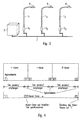
- FIG. 5 schematically represents the forwarding of a forward telegram in a network, wherein the vertical axis represents the time (in transmission and reception cycles), while the horizontal axis indicates the distance of the telegram from the place of origin. This distance is given in so-called.
- Logical repeater stages and corresponds to the number of repetitions of a reception of the telegram in a cycle and the forwarding in the immediately following cycle.
- a double arrow corresponds to the event that a telegram is sent to the network, while a circle represents that a subscriber is ready to receive.
- the network coupler NK sends the telegram intended for the subscriber 5, which is received simultaneously by the adjacent subscriber 1.
- the subscriber 1 in the cycle 1 sends the telegram one more time into the power grid, this now being received by the adjacent subscriber 2. This also sends the telegram in the next cycle 3 in the network. At this time, both the subscriber 1 and the subscriber 3 will be the one sent by the subscriber 2 Receive telegram. However, since the subscriber 1 recognizes that he has already forwarded this telegram to an earlier point in time, the telegram is forwarded in the subsequent cycle 3 exclusively by the subscriber 3, the subscriber 1 preferably suppresses a further transmission. This forwarding of the telegram finally continues until the telegram has arrived at the addressed subscriber 5 - represented by the triangle.
- Essential for the illustrated transmission method is that the participants connected via a power network have a common time frame for sending telegrams.
- a synchronization can be done for example by monitoring the zero crossing of the mains voltage and by a telegram itself, as for example in FIG. 6 is shown.
- a telegram is fed into the network, which - as described above - propagates across the network and thereby ensures synchronization of all participants to the network coupler NK.
- the synchronization is additionally improved in that the synchronization telegram is sent by the network coupler NK and the other participants each in two consecutive cycles.
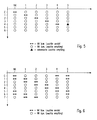
- FIG. 7 now represents the propagation of a forward telegram and the feedback on a backward telegram, with all telegrams are repeated once to increase the transmission reliability.
- the network coupler NK sends a system message, which is directed to the subscriber 3 and prompts the latter to report an operating information.
- the forward telegram propagates so that during cycle 2 it is fed by the subscriber 2 into the network and received by the subscriber 3, again represented by the triangle.
- this subscriber 3 does not forward the forward telegram in the subsequent cycles 3 and 4, but instead sends a backward telegram which is sent to the Network coupler NK is addressed and contains the corresponding information.
- This backward telegram now propagates in all directions across the network until finally in the cycle 5 it is repeated by the first subscriber and thus received by the network coupler NK.
- the network coupler NK could already have sent another forward telegram because, due to the division of a cycle into the three channels, the forward and backward telegrams can run independently in different directions of transfer. This example thus illustrates that by dividing a transmit and receive cycle into three independent channels, data throughput can be increased.
- FIG. 8 finally shows a case in which the subscriber 4 sends an I-telegram due to an extraordinary event, which is transmitted independently of the indicated forward or backward telegrams to the network coupler NK in the manner described above.
- the data traffic just described by means of powerline communication takes place only between a network coupler and connected via a power grid lights.
- the other data transfers, however, are made by other communication techniques, which are not further explained below.
- the lights To address each of the individual lights individually or in groups, the lights have an operating address, which is divided into a corresponding group and individual address. In particular, this operating address may contain information about the geographical location of the luminaire.
- the lights of the outdoor lighting system can be displayed on a screen of the central server 3 in a graphical interface.
- the states of the individual luminaires can be displayed, for example their current brightness status or other information concerning the functionality of the individual luminaires.
- the presentation on a graphical user interface offers the possibility of addressing a specific part of the luminaires in a particularly simple and descriptive manner in order to convey individual commands to them.
- the desired lights or the corresponding area with the help of an input device - for example, a mouse - be marked.
- the within the marked area lying lights then automatically receive the desired instruction.
- the operation of the outdoor lighting system can be controlled in a particularly simple manner.
- each luminaire contains a suitable GPS receiver which permits an accurate determination of the position. This data can be reported back to the central server 3 or the maintenance center 4 via the various communication levels.
- the lights L - as in Fig. 2 shown - can be connected to a suitable GPS device 7 so that, for example, during installation, the corresponding location data from the light L can be stored.
- the location data stored in the lights L can also be used in a further inventive function of the lights L beyond. They have the ability to operate autonomously to some degree if they do not receive orders. This is made possible by the lights L having a memory in which the last received brightness commands are stored. These commands represent an action list, which is independently executed by a light L, if no new commands are received.
- the lights L include an internal clock, which ensures the timely execution of the action list, so that a light L, for example, in the evening at 20:00 clock turns on and off in the morning at 7:00 clock again. The synchronization of the internal clock can be done, for example, with the help of transmitted over the power network time data.
- the lights L can also have one in the Fig. 2 and 3 illustrated light sensor 8 whose input signal is taken into account in the brightness control of the lights L.
- the detected by the light sensors 8 data can also be transmitted in the context of a cyclic polling to the central server 3 in order to be able to take into account appropriate information for controlling the system at a central location.
- the lights L may also contain other sensors for detecting environmental parameters, such as temperature or the like.
- the in the Fig. 2 and 3 The sensor shown can generally be provided for the detection of environmental parameters, which are then taken into account in the execution of the commands.
- the sensor may also be used to detect the temperature or the presence of fog.
- a tilt sensor which can be used to determine whether the luminaire has been damaged or tilted due to external influences, for example an accident or the like.
- the action list for the previously described free-running function of the lights L is - as described - created by the fact that the lights L store the last commands received during normal operation.
- the freewheeling function can also be selectively used in that the lights L at the beginning of operation once a corresponding action list is transmitted. Subsequently, however, no further commands are made.
- the lamps L then work independently until they contain new commands at some point later.
- the storage of a corresponding action list can alternatively also take place via a powerline interface via which, for example, a laptop 9 or the like is connected.
- the lights L can be programmed independently of an outdoor lighting system and then work independently.
- the outdoor lighting system according to the invention is thus characterized by the diverse functionality of the individual lights, which can work largely independently under consideration of corresponding environmental parameters, but at the same time are also suitable for extensive data exchange with other lights or a central control unit.
- the repeater function of the luminaires enables reliable data transfer over the power network even over long distances, without the need for additional data lines.
Abstract
Description
Die vorliegende Erfindung betrifft ein Steuerungssystem für elektrische Geräte wie Außenlichtanlagen bzw. ein Verfahren zum Betreiben von Außenlichtanlagen.The present invention relates to a control system for electrical devices such as outdoor lighting systems or a method for operating outdoor lighting systems.
Durch die in den letzten Jahren entwickelten Steuergeräte zum Betreiben vom Lampen wurde die Möglichkeit eröffnet, komplexe Beleuchtungssysteme zu bilden, bei denen die verteilt angeordneten Leuchten von einer Zentraleinheit individuell angesteuert werden. Derartige Beleuchtungssysteme kommen beispielsweise in größeren Gebäuden zum Einsatz, wobei die Leuchten üblicherweise zum einen an das normale Stromversorgungsnetz angeschlossen und zum anderen über eine Busleitung mit der Zentraleinheit verbunden sind. Über diese Busleitung werden von der Zentraleinheit digitale Befehle an die Steuergeräte der dezentral angeordneten Leuchten übermittelt.The control devices for operating lamps, which have been developed in recent years, have opened up the possibility of forming complex illumination systems in which the distributed luminaires are individually controlled by a central unit. Such lighting systems are used, for example, in larger buildings, the lights are usually connected to the one to the normal power supply network and connected to the other via a bus line to the central unit. Via this bus line, digital commands are transmitted from the central unit to the control units of the decentrally arranged lights.
Ein entsprechender Aufbau wäre selbstverständlich auch bei Außenlichtanlagen - beispielsweise zur Straßenbeleuchtung oder dergleichen - möglich, die Schwierigkeit besteht dann allerdings darin, eine Übertragung der Steuerbefehle von der Zentraleinheit aus zu den weit entfernt angeordneten Leuchten zu ermöglichen. Das Verlegen von Busleitungen ist bei Außenlichtanlagen wegen der relativ großen Entfernungen und des damit verbundenen Aufwands in der Regel nur schwer oder sogar gar nicht möglich.A corresponding structure would of course also in outdoor lighting systems - for example, for street lighting or the like - possible, but the difficulty then is to allow transmission of the control commands from the central unit to the far away lights. The laying of bus lines is usually difficult or even impossible in outdoor lighting systems because of the relatively large distances and the associated effort.
Dennoch wäre auch bei Außenlichtanlagen eine komfortable und vielfältige Steuerung der einzelnen Leuchten von zentraler Stelle aus wünschenswert, um beispielsweise eine bedarfsgerechte Beleuchtung bestimmter Bereiche, Ereignisse oder Veranstaltungen zu ermöglichen. Hierdurch kann der Beleuchtungskomfort aber auch die Sicherheit erhöht werden. Darüber hinaus trägt eine Kommunikation zwischen den Leuchten und einer Zentraleinheit zu einer Reduzierung des Wartungsaufwandes und zum Energiesparen bei. Dies setzt allerdings voraus, daß die Leuchten individuell angesteuert werden können und ein kommunikationsfähiges System zum Einsatz kommt, welches eine gezielte Status- bzw. Fehlererkennung und Fehlerrückmeldung ermöglicht.Nevertheless, even in outdoor lighting systems a comfortable and diverse control of the individual lights would be desirable from a central location, for example, to enable needs-based lighting of certain areas, events or events. As a result, the lighting comfort but also the safety can be increased. In addition, communication between the lights and a central unit reduces maintenance and saves energy. However, this requires that the lights can be controlled individually and a communication-capable system is used, which allows targeted status or error detection and error feedback.
Eine alternative Möglichkeit zur Datenübertragung ohne die Notwendigkeit zusätzlicher Busleitungen besteht in der sog. Powerline-Technologie. Hierbei werden die Strom- bzw. Spannungsversorgungsleitungen selbst für die Datenübertragung benutzt, indem auf die normale Netzfrequenz von 50 Hz eine modulierte höherfrequente Trägerfrequenz aufgebracht wird. Die Trägerfrequenz enthält in verschlüsselter Form die zu übertragenden Informationen, welche von entsprechenden Empfängern entschlüsselt werden. Derartige Powerline-Verfahren kommen bereits bei einigen Beleuchtungsanlagen zur Gebäudebeleuchtung oder anderen haus-internen Steueranlagen zum Einsatz, wobei hier das interne Stromnetz zur Datenübertragung verwendet wird. Eine Übersicht über die verschiedenen Funktionsweisen und Möglichkeiten der Powerline-Technologie kann dem Buch "Powerline Kommunikation" von Klaus Dostert, Franzis Verlag GmbH, entnommen werden. Insofern werden diese Grundlagen im Vorliegenden nicht wiederholt.An alternative possibility for data transmission without the need for additional bus lines is in the so-called. Powerline technology. In this case, the power supply lines themselves are used for data transmission by modulating to the normal line frequency of 50 Hz higher frequency carrier frequency is applied. The carrier frequency contains in encrypted form the information to be transmitted, which are decrypted by corresponding receivers. Such power line methods are already used in some lighting systems for building lighting or other home-internal control systems, in which case the internal power network is used for data transmission. An overview of the different functions and possibilities of Powerline technology can be found in the book "Powerline Kommunikation" by Klaus Dostert, Franzis Verlag GmbH. In this respect, these basics are not repeated in the present.
Verfahren zur Übertragung von digitalen Informationen über das Stromversorgungsnetz sind ferner in der
Für Außenlichtanlagen ist die Verwendung eines Powerline-Verfahrens insofern problematisch, als sehr große Entfernungen zwischen dem Sender und dem Empfänger sowie deutliche Temperaturschwankungen auftreten können. Aufgrund der hierdurch entstehenden Dämpfungen und Störungen der Signale ist nicht ohne weiteres sichergestellt, daß die Informationen auch richtig empfangen und umgesetzt werden. Für einen zuverlässigen Betrieb der Anlage allerdings ist eine Datenübertragung mit hoher Sicherheit gegenüber unerkannten Übertragungsfehlern unerläßlich. Dabei ist zu berücksichtigen, daß der maximal zulässige Signalpegel (dBµV) durch Normen begrenzt ist. In Europa ist beispielsweise seit 1991 die CENELEC-Norm EN 50065 gültig, gemäß der in dem für die private Nutzung vorgesehenen Frequenzbereich von 95 kHz bis 148,5 kHz - der beispielsweise für gebäude-interne Systeme zur Verfügung steht - ein maximaler Einspeisepegel von 116 dBµV (=631 mV effektiv) zulässig ist. In dem für Energieversorgungsunternehmen reservierten Frequenzbereich zwischen 9 kHz und 95 kHz, fällt der maximal zulässige Signalpegel von 134 dBµV (= 5 V) auf 122 dBµV (=1,25 V) ab. Diese relativ starken Beschränkung erschweren die Realisierung eines Systems zur Fernsteuerung von Leuchten mittels Powerline-Kommunikation. Diese Probleme stellen sich natürlich nicht nur bei Lichtanlagen, sondern bei allen elektrischen Geräten im Außenbereich.For outdoor lighting systems, the use of a powerline method is problematic in that very large distances between the transmitter and the receiver and significant temperature fluctuations can occur. Due to the resulting attenuation and interference of the signals is not readily ensured that the information is also received and implemented correctly. For a reliable operation of the system, however, a data transmission with high security against unrecognized transmission errors is essential. It should be noted that the maximum permissible signal level (dBμV) is limited by standards. In Europe, for example, the CENELEC standard EN 50065 has been in force since 1991, according to the frequency range from 95 kHz to 148.5 kHz intended for private use - which is available, for example, for building-internal systems - with a maximum feed-in level of 116 dBμV (= 631 mV effective) is allowed. In the frequency range between 9 kHz and 95 kHz reserved for power companies, the maximum permissible signal level of 134 dBμV (= 5 V) drops to 122 dBμV (= 1.25 V). This relatively strong limitation complicates the realization of a system for the remote control of lights by means of powerline communication. Of course, these problems do not only arise with lighting systems, but with all outdoor electrical devices.
Es ist daher Aufgabe der vorliegenden Erfindung, ein Gesamtkonzept für ein Steuerungssystem zum Betreiben von elektrischen Geräten im Außenbereich anzugeben, bei dem die Datenübertragung durch ein Powerline-Verfahren erfolgt und eine zuverlässige und fehlerfreie Kommunikation sichergestellt ist. Darüber hinaus soll ein vielseitiger und störungsfreier Betrieb - beispielsweise der Leuchten - ermöglicht werden.It is therefore an object of the present invention to provide an overall concept for a control system for operating electrical devices in the outdoor area, in which the data transmission is carried out by a power-line method and a reliable and error-free communication is ensured. In addition, a versatile and trouble-free operation - for example, the lights - are made possible.
Die Aufgabe wird durch die in den unabhängigen Ansprüchen definierten Verfahren bzw. Vorrichtungen gelöst.The object is achieved by the methods and devices defined in the independent claims.
Ein erster Aspekt der Erfindung betrifft ein Verfahren zum Steuern von elektrischen Geräten, insbesondere von Leuchten, die an ein gemeinsames Stromversorgungsnetz angeschlossen sind. Erfindungsgemäß tauschen dabei die elektrischen Geräte mittels einem Powerline-Verfahren Informationen mit einer Steuereinheit über das Stromversorgungsnetz aus, wobei die elektrischen Geräte derart zueinander synchronisiert sind, daß sie in vorgegebenen Sende- und Empfangszyklen Informationen von dem Stromversorgungsnetz empfangen bzw. in dieses senden. Dabei wirkt jedes elektrische Gerät als sog. Repeater, indem es eine in einem Sende- und Empfangszyklus empfangene Information - im Folgenden als Telegramm bezeichnet - in einem mittelbar oder unmittelbar folgenden Sende- und Empfangszyklus wieder in das Stromversorgungsnetz sendet.A first aspect of the invention relates to a method for controlling electrical devices, in particular lights, which are connected to a common power supply network. According to the invention, the electrical devices exchange information with a control unit via the power supply network by means of a powerline method, with the electrical devices being synchronized with one another in such a way that they receive information from the power supply network or transmit it to the power supply network during predetermined transmission and reception cycles. In this case, each electrical device acts as a so-called. Repeater by it sends a received in a transmission and reception cycle information - hereinafter referred to as a telegram - in an indirectly or immediately following transmission and reception cycle back into the power grid.
Diese Vorgehensweise hat zur Folge, daß sich ein an einer beliebigen Stelle in das Stromversorgungsnetz eingespeistes Telegramm gleichsam lawinenartig über das gesamte Netz ausbreitet, bis es schließlich von dem andressierten elektrischen Gerät empfangen wird. Vorzugsweise kann vorgesehen sein, daß ein elektrisches Gerät ein Telegramm nur dann weiterleitet, wenn dieses Telegramm nicht ausschließlich für das jeweilige elektrische Gerät selbst bestimmt ist.As a result of this procedure, a telegram fed in at any desired point into the power supply network spreads, as it were, like an avalanche over the entire network until finally it is received by the addressed electrical device. Preferably, it can be provided that an electrical device only forwards a telegram if this telegram is not exclusively intended for the respective electrical device itself.
Durch die Synchronisation der elektrischen Geräte zueinander wird sichergestellt, daß keine Auslöschung eines von zwei benachbarten elektrischen Geräten gesendeten identischen Telegramms erfolgt. Hierdurch wird auch über eine größere Distanz hinweg eine zuverlässige Datenübertragung gewährleistet. Gleichzeitig wird auch ein hoher Datendurchsatz erreicht, da die elektrischen Geräte in ihrer Repeater-Funktion zeitgleich in verschiedenen Bereichen des Netzes verschiedene Telegramme senden können. Da dies ohne eine Signalstärkenbewertung stattfindet, zeichnet sich das erfindungsgemäße Verfahren insbesondere dadurch aus, daß hiermit auf einfache Weise ein hoher Datendurchsatz mit einer geringen Fehlerquote erzielt wird.By synchronizing the electrical devices with each other, it is ensured that there is no cancellation of an identical telegram sent by two adjacent electrical devices. As a result, a reliable data transmission is ensured even over a greater distance. At the same time, a high data throughput is achieved because the electrical devices in their repeater function can simultaneously send different telegrams in different areas of the network. Since this takes place without a signal strength evaluation, the method according to the invention is characterized in particular by the fact that in this way a high data throughput with a low error rate is achieved in a simple manner.
Gemäß einer Weiterbildung kann vorgesehen sein, daß die elektrischen Geräte eine weiterzuleitende Information für eine vorgegebene Anzahl von aufeinanderfolgenden Sende- und Empfangszyklen in das Stromversorgungsnetz senden. Hierdurch wird die Übertragungssicherheit erhöht. Darüber hinaus kann vorgesehen sein, daß die elektrischen Geräte in der Lage sind, bereits einmal empfangene und weitergeleitete Telegramme wiederzuerkennen, so daß sie ein zu einem späteren Zeitpunkt ein weiteres Mal empfangenes Telegramm nicht mehr weiterleiten. Hierdurch wird verhindert, daß Telegramme in Endlosschleifen durch das Netz laufen. Diese Wiedererkennung kann beispielsweise durch eine geeignete Indizierung (Indexnummer etc.) der Telegramme ermöglicht werden.According to a further development, it can be provided that the electrical devices send information to be forwarded to the power supply network for a predetermined number of successive transmission and reception cycles. This increases the transmission reliability. In addition, it can be provided that the electrical equipment are able to recognize once received and forwarded telegrams so that they one at a later time once again received telegram no longer forward. This prevents telegrams from running in endless loops through the network. This recognition can be made possible for example by a suitable indexing (index number etc.) of the telegrams.
Die Datenübertragung erfolgt vorzugsweise durch eine Phasenmodulation der Trägerfrequenz (sogenanntes Phase Shift Keying - PSK). Dieses Verfahren zeichnet sich durch seine geringe Störanfälligkeit aus. Eine Synchronisation der verschiedenen Leuchten erfolgt dabei durch eine Überwachung der Netzfrequenz.The data transmission is preferably carried out by a phase modulation of the carrier frequency (so-called phase shift keying - PSK). This method is characterized by its low susceptibility to interference. A synchronization of the different lights is done by monitoring the grid frequency.
Dieser Aspekt der Erfindung betrifft auch ein Steuerungssystem für elektrische Geräte, insbesondere für Leuchten, die an ein gemeinsames Stromversorgungsnetz angeschlossenen sind, wobei das Steuerungssystem mindestens eine ebenfalls an das Stromversorgungsnetz anschließbare Steuereinheit sowie Sende- und Empfangseinheiten aufweist, die mit einem Powerline-Verfahren Informationen mit der Steuereinheit über das Stromversorgungsnetz austauschen und jeweils einem elektrischen Gerät zugeordnet werden können. Die Sende- und Empfangseinheiten sind dabei in der oben beschriebenen Weise zueinander synchronisiert und weisen zum Weiterleiten der Informationen die erfindungsgemäße Repeater-Funktion auf. Ein solches Steuerungssystem kann ggf. bei bestehenden Lichtanlagen im Außenbereich nachgerüstet werden.This aspect of the invention also relates to a control system for electrical devices, in particular for lights, which are connected to a common power supply network, wherein the control system has at least one also connectable to the power supply control unit and transmitting and receiving units with a powerline process with information the control unit via the power supply network and each can be assigned to an electrical device. The transmitting and receiving units are synchronized with each other in the manner described above and have to forward the information to the inventive repeater function. Such a control system can optionally be retrofitted to existing outdoor lighting systems.
Ferner betrifft diese Erfindung auch eine Leuchte für eine Lichtanlage, die aus mehreren an ein gemeinsames Stromversorgungsnetz angeschlossen Leuchten besteht, wobei die Leuchte eine Sende- und Empfangseinheit aufweist, die als Schnittstelle gemäß dem Powerline-Verfahren ausgelegt ist. Die Sende- und Empfangseinheit ist dabei derart ausgestaltet, daß sie in vorgegebenen Sende- und Empfangszyklen Informationen austauschen kann, wobei sie zum Übertragen der Informationen eine Repeater-Funktion aufweist, indem sie eine in einem Sende- und Empfangszyklus empfangene Information in einem mittelbar oder unmittelbar folgenden Sende- und Empfangszyklen wieder sendet.Furthermore, this invention also relates to a lamp for a lighting system, which consists of several connected to a common power grid lights, the lamp has a transmitting and receiving unit, which is designed as an interface according to the powerline method. The transmitting and receiving unit is designed such that it can exchange information in predetermined transmission and reception cycles, wherein it has a repeater function for transmitting the information by a received in a transmission and reception cycle information in a direct or indirect sends the following send and receive cycles again.
Ein zweiter Aspekt der vorliegenden Erfindung betrifft die zeitliche Struktur der Datenübertragung. So können die zu übertragenden Daten bzw. Telegramme entsprechend ihrer Funktion in verschiedene Gruppen unterteilt werden. Sogenannte Systemtelegramme sind beispielsweise dafür zuständig, daß sich die Leuchten in dem System anmelden können bzw. abgemeldet werden. Darüber hinaus haben diese Systemtelegramme die Aufgabe, Daten - beispielsweise Adressdaten, Meßdaten, Betriebsdaten oder -fehler - zwischen einer mit dem Netz verbundenen Steuereinheit und den Leuchten auszutauschen. Daneben kommen sogenannte Anwendertelegramme zum Einsatz, mit welchen die Leuchten dazu veranlaßt werden, eine bestimmte Funktion auszuführen, beispielsweise sich einzuschalten oder die Helligkeit zu verändern. Da diese Anwendertelegramme die eigentlichen Steuerbefehle zum Betreiben der Leuchten und zum Einstellen der Helligkeit beinhalten, besitzen diese Telegramme eine höhere Priorität als die zuvor erwähnten Systemtelegramme.A second aspect of the present invention relates to the temporal structure of the data transmission. Thus, the data or telegrams to be transmitted can be divided into different groups according to their function. So-called system telegrams are responsible, for example, for the luminaires being able to log into the system or being logged off. In addition, these system telegrams have the task of data - for example, address data, measurement data, operating data or errors - between a connected to the network control unit and replace the lights. In addition, so-called user telegrams are used, with which the lights are caused to perform a certain function, for example, turn on or change the brightness. Since these user telegrams contain the actual control commands for operating the luminaires and for adjusting the brightness, these telegrams have a higher priority than the system telegrams mentioned above.
Eine andere Möglichkeit der Unterscheidung besteht darin, die verschiedenen Telegramme entsprechend ihres Zielortes in Vorwärtstelegramme, Rückwärtstelegramme und I-(Interrupt)-Telegramme zu unterteilen. Als Vorwärtstelegramme werden diejenigen Telegramme bezeichnet, die von einer Steuereinheit abgesendet wurden und an eine oder mehrere der Leuchten adressiert sind. Dies sind beispielsweise Helligkeitsbefehle, Ein- und Ausschaltbefehle, Abfragen etc. Rückwärtstelegramme hingegen sind Informationen, welche von den Leuchten als Antwort auf ein Vorwärtstelegramm an die Steuereinheit zurückgesendet werden. Hierbei kann es sich beispielsweise um Statusinformationen, die Übermittlung eines Meßwertes oder dergleichen handeln. Vorzugsweise wird ein solches Rückwärtstelegramm nur dann von einer Leuchte gesendet, wenn sie zuvor über ein entsprechendes Vorwärtstelegramm dazu aufgefordert wurde. Ein I-Telegramm schließlich kann dann von einer Leuchte gesendet werden, wenn ein besonderes Ereignis innerhalb der Leuchte aufgetreten ist - beispielsweise ein Lampendefekt - der möglichst schnell an die Zentrale gemeldet werden muß.Another possibility of differentiation is to divide the various telegrams according to their destination into forward telegrams, backward telegrams and I (interrupt) telegrams. Forward telegrams are those telegrams that have been sent by a control unit and addressed to one or more of the lights. These are, for example, brightness commands, switch-on and switch-off commands, queries, etc. Backward telegrams, on the other hand, are information which is sent back to the control unit by the luminaires in response to a forward telegram. This may be, for example, status information, the transmission of a measured value or the like. Preferably, such a backward telegram is only sent by a luminaire if it was previously requested to do so via a corresponding forward telegram. Finally, an I-telegram can be sent by a luminaire when a special event has occurred inside the luminaire - for example a lamp defect - which must be reported to the control center as quickly as possible.
Gemäß dem zweiten Aspekt der vorliegenden Erfindung ist bei einem Verfahren zum Steuern von elektrischen Geräten, insbesondere von Leuchten, die mittels einem Powerline-Verfahren Informationen über das gemeinsame Stromversorgungsnetz austauschen können, vorgesehen, daß die Übertragung dieser Informationen synchronisiert in aufeinanderfolgenden Sende- und Empfangs-Zyklen stattfindet, wobei ein Sende- und Empfangszyklus in mindestens zwei Zeitabschnitte - im Folgenden auch als Kanäle bezeichnet - unterteilt ist. Ein erster Zeitabschnitt ist dabei zum Übertragen von Steuerbefehlen bzw. Abfragebefehlen zu den elektrischen Geräten vorgesehen, der zweite, zeitlich von dem ersten getrennte Zeitabschnitt ist zum Übertragen von Betriebs- oder Statusinformationen ausgehend von den elektrischen Geräten vorgesehen.According to the second aspect of the present invention, in a method for controlling electrical devices, in particular lamps, which can exchange information via the common power supply network by means of a powerline method, it is provided that the transmission of this information be synchronized in successive transmission and reception Cycles takes place, wherein a transmission and reception cycle in at least two time periods - hereinafter also referred to as channels - is divided. A first period of time is provided for transmitting control commands or interrogation commands to the electrical appliances, the second time period separated from the first time period is provided for transmitting operating or status information from the electrical appliances.
In einem Zyklus kann somit von jedem Teilnehmer genau ein Vorwärtstelegramm und ein Rückwärtstelegramm übertragen werden. Wird daher beispielsweise von der Steuereinheit ein Systemtelegramm als Vorwärtstelegramm an eine bestimmte Leuchte geschickt, um z.B. deren Status abzufragen, so ist es nicht notwendig, daß vor dem Absenden eines weiteren Vorwärtstelegramms eine Antwort der Leuchte in Form eines Rückwärtstelegramms abgewartet wird, da die Übertragung von Vorwärts- und Rückwärtstelegrammen unabhängig voneinander erfolgt. Hierdurch können selbst bei größeren Laufzeiten für einzelne Telegramme hohe Übertragungsraten erzielt werden, da mehrere Telegramme gleichzeitig übertragen werden können.In a cycle, exactly one forward telegram and one backward telegram can be transmitted by each participant. If, for example, the control unit sends a system telegram as a forward telegram to a specific luminaire, in order, for example, to query its status, it is not necessary for the system telegram to be forwarded to it Send a further forward telegram a response of the lamp is waiting in the form of a Rückwärtstelegramms, since the transmission of forward and backward telegrams is independent of each other. As a result, high transmission rates can be achieved for individual telegrams, even with longer propagation times, since several telegrams can be transmitted simultaneously.
Die Anwendertelegramme haben vorzugsweise eine höhere Priorität. Im Gegensatz dazu laufen routinemäßige Systemtelegramme zum zyklischen Abfragen der Betriebszustände der Leuchten vorzugsweise im Hintergrund ab. Möchte daher die Steuereinheit einen bestimmten Steuerbefehl an eine Leuchte senden, unterbricht sie hierfür das zyklische Senden der Abfragebefehle.The user telegrams preferably have a higher priority. In contrast, routine system telegrams for cyclically polling the operating states of the luminaires preferably run in the background. Therefore, if the control unit wants to send a specific control command to a luminaire, it interrupts the cyclical transmission of the interrogation commands for this purpose.
Vorzugsweise ist ein Sende- und Empfangszyklus sogar in drei Zeitabschnitte unterteilt, wobei der dritte Zeitabschnitt zum Übertragen von Ereignismeldungen vorgesehen ist, die von einem elektrischen Gerät bzw. einer Leuchte ausgesendet werden. Dieser asynchrone Kanal stellt sicher, daß diese besonderen Ereignismeldungen möglichst umgehend der Steuereinheit mitgeteilt werden können.Preferably, a transmission and reception cycle is even divided into three time periods, wherein the third time period is provided for transmitting event messages that are emitted by an electrical device or a lamp. This asynchronous channel ensures that these special event messages can be communicated to the control unit as soon as possible.
Auch dieser zweite Aspekt der Erfindung betrifft ein Steuerungssystem für elektrische Geräte bzw. Leuchten, die Sende- und Empfangseinheiten aufweisen, über die ihnen mit einem Powerline-Verfahren Informationen zum Betreiben der elektrischen Geräte von einer Steuereinheit über das Stromversorgungsnetz übermittelbar sind, wobei die Sende- und Empfangseinheiten der elektrischen in der oben beschriebenen Weise zueinander synchronisiert sind und ein Sende- und Empfangszyklus in mindestens zwei Zeitabschnitte unterteilt ist, von denen ein Zeitabschnitt zum Übertragen von Steuerbefehlen bzw. Abfragebefehlen zu einem elektrischen Gerät und der andere, zeitlich getrennte Zeitabschnitt zum Übertragen von Betriebs- oder Statusinformationen eines elektrischen Geräts zu der Steuereinheit vorgesehen ist.This second aspect of the invention also relates to a control system for electrical devices or luminaires, which have transmitting and receiving units, via which information about the operation of the electrical devices can be transmitted from a control unit via the power supply network using a power-line method. and receiving units of the electrical in the manner described above are synchronized with each other and a transmission and reception cycle is divided into at least two time periods, of which a period for transmitting control commands or interrogation commands to an electrical device and the other, time-separated period for transmitting Operating or status information of an electrical device to the control unit is provided.
Schließlich betrifft dieser zweite Aspekt der Erfindung auch eine Leuchte mit einer Schnittstelle, über die ihr mit einem Powerline-Verfahren Betriebsinformationen über ihre Stromversorgung übermittelbar sind, wobei die Schnittstelle derart ausgestaltet ist, daß sie in vorgegebenen Sende- und Empfangszyklen Informationen über die Stromversorgung empfängt bzw. aussendet, und wobei ein Sende- und Empfangszyklus in mindestens zwei Zeitabschnitte unterteilt ist, von denen ein Zeitabschnitt zum Übertragen von Steuerbefehlen bzw. Abfragebefehlen zu der Leuchte und der andere Zeitabschnitt zum Aussenden von Betriebs- oder Statusinformationen von der Leuchte vorgesehen ist.Finally, this second aspect of the invention also relates to a luminaire having an interface via which operating information about its power supply can be transmitted by means of a powerline method, the interface being designed such that it receives or receives information about the power supply in predetermined transmission and reception cycles , and wherein a transmission and reception cycle is subdivided into at least two time periods, of which a time period is provided for transmitting control commands to the light and the other time period for transmitting operation or status information from the light.
Ein dritter Aspekt der vorliegenden Erfindung betrifft schließlich die Fähigkeit der Leuchten, während einer Störung der Datenübertragung oder des Nichtempfangens von neuen Befehlen autonom weiterzuarbeiten. Dies wird erfindungsgemäß dadurch erreicht, daß eine Leuchte zumindest einen Teil der empfangenen Informationen, welche als Steuerbefehle die Helligkeitssteuerung der Leuchte betreffen, speichert und diese gespeicherten Befehle selbständig wiederholt ausführt, sofern sie keine anderslautenden Informationen erhält. Die gespeicherten Befehle bilden somit eine Aktionsliste, die von der Leuchte fortwährend abgearbeitet wird, so daß ein unabhängiger Betrieb gewährleistet wird.Finally, a third aspect of the present invention relates to the ability of the lights to autonomously continue to operate during a disruption of data transmission or not receiving new commands. This is inventively achieved in that a lamp stores at least a portion of the received information, which relate to the brightness control of the lamp as control commands, and executes these stored commands independently repeatedly, unless they receive any other information. The stored commands thus form an action list, which is continuously processed by the lamp, so that an independent operation is ensured.
Ergänzend besteht dabei die Möglichkeit, die Leuchten in ihrer autonomen Arbeitsweise an die aktuellen Tages- und Jahreszeiten anzupassen, indem Befehle mit einer relativen Zeitangabe bezüglich des Sonnenstands übermittelt werden. Ein solcher Befehl kann beispielsweise die Anweisung beinhalten, die Leuchte zehn Minuten vor Sonnenuntergang auf 50% der maximalen Helligkeit einzuschalten. Hierzu kennt die Leuchte ihre Standortdaten und enthält eine interne Uhr zum Feststellen der aktuellen Zeit- und Datumsinformationen. Auf Grundlage dieser Informationen kann die Leuchte den aktuellen Sonnenstand und damit auch den tatsächlichen Zeitpunkt zum Ausführen des Befehls berechnen.In addition, there is the possibility of adapting the luminaires in their autonomous mode of operation to the current day and seasons, by commands with a relative time with respect to the position of the sun are transmitted. For example, such a command may include the instruction to turn on the light ten minutes before sunset to 50% of the maximum brightness. For this, the luminaire knows its location data and contains an internal clock for determining the current time and date information. Based on this information, the luminaire can calculate the current position of the sun and thus also the actual time to execute the command.
Eine Ergänzung dieses Konzepts besteht ferner darin, die Leuchten mit verschiedenen Sensoren auszustatten, welche bestimmte Umgebungsparameter erfassen, wie beispielsweise die Helligkeit oder die Temperatur. Auch diese Informationen können beim Betreiben der Leuchte selbstständig berücksichtigt werden oder als entsprechende Informationen an eine Zentrale übermittelt werden.An addition to this concept is also to equip the lights with different sensors that detect certain environmental parameters, such as brightness or temperature. This information can be considered independently when operating the lamp or transmitted as appropriate information to a central office.
Dieser dritte erfindungsgemäße Aspekt betrifft schließlich auch eine Leuchte mit einer Schnittstelle, über die ihr mit einem Powerline-Verfahren Betriebsinformationen über ihre Stromversorgung übermittelbar sind, wobei die Leuchte einen Speicher zum speichern derjenigen empfangenen Informationen aufweist, welche als Steuerbefehle die Helligkeitssteuerung der Leuchte betreffen, und wobei die Leuchte derart ausgestaltet ist, daß sie diese gespeicherten Befehle selbständig wiederholt ausführt, sofern sie keine anderslautenden Informationen erhält.Finally, this third aspect of the invention also relates to a luminaire with an interface via which it can transmit operating information about its power supply by means of a powerline method, the luminaire having a memory for storing those received information relating to the brightness control of the luminaire as control commands, and wherein the lamp is designed such that it executes these stored commands independently repeatedly, unless it receives any other information.
Im Folgenden soll die Erfindung anhand der beiliegenden Zeichnung näher erläutert werden. Es zeigen:
-
Figur 1 -
Figur 2 -
Figur 3 -
Figur 4 -
Figuren 5bis 8
-
FIG. 1 the overall view of an outdoor lighting system; -
FIG. 2 a diagram of the different levels of communication of an embodiment of the light control system according to the invention; -
FIG. 3 a section of the outdoor lighting system according to the invention; -
FIG. 4 a scheme for dividing a transmit and receive cycle into three different channels; and -
FIGS. 5 to 8 schematic representations of the transmission and propagation of telegrams within a network.
Die Erfindung wir hier anhand des Beispiels einer Außenlichtanlage erläutert, deren Leuchten gemäß der vorliegenden Erfindung angesteuert werden. Gleichwohl kann die Erfindung allgemein für elektrische Geräte verwendet werden, die an ein gemeinsames Stromversorgungsnetz angeschlossen sind und über dieses angesteuert werden sollen. Dabei kann es sich sowohl um aktive Geräte wie Lüfter oder dergleichen als auch um passive Geräte, beispielsweise Sensoren etc. handeln. Insbesondere wäre auch die Realisierung eines Netzes von Sensoren denkbar, die über das gemeinsame Stromversorgungsnetz ihre Meßdaten an eine Zentrale übermitteln.The invention is explained here on the basis of the example of an outdoor lighting system whose luminaires are controlled according to the present invention. However, the invention can generally be used for electrical devices that are connected to a common power supply network and to be controlled via this. These can be both active devices such as fans or the like as well as passive devices, such as sensors, etc. In particular, the realization of a network of sensors would be conceivable that transmit their measurement data via the common power supply network to a central office.
Im Folgenden soll zunächst anhand der
Der zum Beispiel in einem Schaltschrank vor Ort angeordnete Netzkoppler 2 kann darüber hinaus mit übergeordneten Steuereinheiten in Verbindung treten, z.B. mit dem Zentralserver eines Managementsystems 3 - der sich im dargestellten Beispiel der Straßenbeleuchtung beispielsweise im Stadtbauamt befinden kann - oder einer Wartungszentrale 4 zur Überwachung der Funktionsfähigkeit der gesamten Anlage.The
Die Kommunikation zwischen dem Netzkoppler 2 und den übergeordneten Steuereinheiten 3 und 4 erfolgt durch andere Datenübertragungsverfahren und kann in mehrere Hierarchieebenen eingeteilt sein, wie dies beispielsweise in
Die Netzkoppler 2 sind über serielle Datenleitungen 5 mit einem Kommunikator 6 verbunden, der eine Zwischenebene in der Verwaltungsstruktur darstellt. Alternativ zu den seriellen Datenleitungen 5 kann die Kommunikation zwischen dem Kommunikator 6 und den Netzkopplern 2 auch per Funk erfolgen. Mehrere Kommunikatoren 6 sind schließlich mit dem Zentralserver des Managementsystems 3 verbunden, welches die Steuerung der Anlage insgesamt verwaltet. Eine Kommunikation zwischen dem Managementsystem 3 und den Kommunikatoren 6 erfolgt über DFÜ-Verbindungen, beispielsweise über das Internet oder Funk. Darüber hinaus kann eine Verbindung zu der zentralen Servicestelle 4 erstellt werden, welche für die Wartung und Überprüfung der Funktionsfähigkeit der Anlage zuständig ist.The
Ein wesentlicher Aspekt der vorliegenden Erfindung betrifft die Powerline-Kommunikation zwischen einem Netzkoppler 2 und den mit diesem verbundenen Leuchten L. Hier kommt ein Verfahren zum Einsatz, welches in einfacher Weise eine zuverlässige Datenübertragung über das Stromversorgungsnetz 1 sicherstellt. Dieses soll daher im Folgenden näher erläutert werden.An essential aspect of the present invention relates to the power line communication between a
Zur Datenübertragung erfolgt eine Phasenmodulation (PSK - Phase Shift Keying) einer hochfrequenten Trägerfrequenz von beispielsweise 104,2 kHz, die wiederum der Netzfrequenz des Stromversorgungsnetzes 1 überlagert ist. Die mittels PSK-Modulation zu übertragenden Informationen sind zeitlich in sogenannte Telegramme gebündelt, die von den Sende- und Empfangseinheiten S1 bis S3 der Leuchten L1 bis L3 sowie dem Netzkoppler 2 entschlüsselt werden können. Jedes Telegramm entspricht dabei festgelegten Konventionen und enthält eine Adresse, die angibt, an welchen bzw. welche Teilnehmer das entsprechende Telegramm gerichtet ist. Insbesondere besteht die Möglichkeit, die Leuchten L1 bis L3 einzeln oder in Gruppen anzusteuern.For data transmission is a phase modulation (PSK - phase shift keying) of a high-frequency carrier frequency of 104.2 kHz, for example, which is in turn superimposed on the network frequency of the
Das oben beschriebene Powerline-Verfahren ist grundsätzlich bereits bekannt und soll daher im Weiteren nicht näher erläutert werden. Von wesentlicher Bedeutung ist allerdings, daß die an das Stromversorgungsnetz 1 angeschlossenen Teilnehmer 2 und L1 bis L3 untereinander synchronisiert sind, was dadurch erreicht wird, daß der Nulldurchgang der Netzspannung verwendet wird, um ein Kanalraster aufzubauen. Diese Synchronisation ist deshalb von Bedeutung, da hierdurch die Möglichkeit besteht, einzelne Sende- und Empfangs-Zyklen zu definieren, die in zeitlich voneinander getrennte Übertragungsabschnitte - im Folgenden als Kanäle bezeichnet - unterteilt werden können, wie dies beispielsweise in
Ein gesamter Sende- und Empfangs-Zyklus besteht dabei aus drei aufeinanderfolgenden Kanälen, einem Vorwärtskanal (F-Kanal), einem Rückwärtskanal (B-Kanal) und einem dazwischenliegenden Interrupt-Kanal (I-Kanal). Die Zeitbasis für die Unterteilung in die drei Kanäle bildet die Netzsynchronisation, wobei alle drei Kanäle über ein im Rahmen des F-Kanals empfangenes Vorwärtstelegramm getriggert werden. Ein B- oder I-Kanal darf lediglich dann aufgebaut werden, falls ein Vorwärtstelegramm empfangen wurde oder der entsprechende Timer der Leuchte L1 bis L3 synchron läuft. Das Senden oder Weiterleiten von Telegrammen ist also nur für synchron laufende Sende- und Empfangseinheiten S1 bis S3 möglich. Hierdurch wird ein unbeabsichtigtes asynchrones Senden von einer nicht synchron laufenden Sende- und Empfangseinheit S1 bis S3 vermieden. Ferner sind die Sende- und Empfangseinheiten S1 bis S3 grundsätzlich empfangsbereit für Vorwärtstelegramme, welche zu einer entsprechenden Synchronisation führen.An entire transmission and reception cycle consists of three consecutive channels, a forward channel (F channel), a backward channel (B channel) and an intermediate interrupt channel (I channel). The time base for the subdivision into the three channels forms the network synchronization, wherein all three channels are triggered via a forward telegram received in the context of the F-channel. A B or I channel may only be set up if a forward telegram has been received or the corresponding timer of the luminaire L 1 to L 3 is running synchronously. The sending or forwarding of telegrams is therefore only possible for synchronously running transmitting and receiving units S 1 to S 3 . As a result, an unintentional asynchronous transmission is avoided by a non-synchronous transmitting and receiving unit S 1 to S 3 . Furthermore, the transmitting and receiving units S 1 to S 3 are always ready to receive forward telegrams, which lead to a corresponding synchronization.
Aufgrund der Unterteilung in die drei zuvor beschriebenen Kanäle können innerhalb eines Sendezyklus gleichzeitig ein Vorwärts-, ein Rückwärts- und ein I-Telegramm übertragen werden. Vorwärtstelegramme stammen von dem Netzkoppler 2 und sind an eine oder mehrere Leuchten L1 bis L3 adressiert. Üblicherweise enthalten die Vorwärtstelegramme eine Aufforderung an die Leuchten L1 bis L3, eine bestimmte Aktion auszuführen, beispielsweise sich ein- oder auszuschalten oder eine bestimmte Helligkeit anzunehmen. Diese Art eines Vorwärtstelegramms betrifft somit die Helligkeitssteuerung der Außenlichtanlage und wird auch als Anwendertelegramm bezeichnet. Darüber hinaus kann das Vorwärtstelegramm auch eine Aufforderung an eine Leuchte L1 bis L3 beinhalten, ihren derzeitigen Informationsstatus oder andere Betriebs- oder Meßparameter zurückzumelden. Da es sich hierbei in erster Linie um einen Datenaustausch bezüglich des Funktionsfähigkeit der Anlage handelt, werden derartige Vorwärtstelegramme auch als Systemtelegramme bezeichnet.Due to the division into the three channels described above, a forward, a backward and an I-telegram can be transmitted simultaneously within one transmission cycle. Forward telegrams originate from the
Im Gegensatz dazu stammt ein Rückwärtstelegramm von einer Leuchte L1 bis L3 und stellt eine Rückmeldung an den Netzkoppler 2 dar. Demzufolge generiert eine Leuchte L1 bis L3 nur dann ein eigenes Rückwärtstelegramm, wenn sie zuvor im Rahmen eines Vorwärtstelegramms - genau genommen eines Systemtelegramms - dazu aufgefordert wurde. Dies kann beispielsweise im Rahmen einer routinemäßigen Abfrage im Sinne eines Polling-Mechanismus erfolgen. Da diese Abfragen die Helligkeitssteuerung der Leuchten L1 bis L3 nicht direkt betreffen, haben sie gegenüber den Anwendertelegrammen eine niedrigere Priorität.In contrast, a Rückwärtstelegramm comes from a lamp L 1 to L 3 and provides feedback to the
Wesentlich ist, daß eine Leuchte L1 bis L3 nur dann von sich aus ein neues Rückwärtstelegramm erzeugt und in das Stromversorgungsnetz 1 sendet, wenn sie dazu aufgefordert wurde. Hierdurch soll verhindert werden, daß die Leuchten L1 bis L3 willkürlich von sich aus Telegramme erzeugen und in das Stromversorgungsnetz 1 senden. Hingegen wird ein in einem Sende- und Empfangszyklus empfangenes Rückwärtstelegramm grundsätzlich in einem mittelbar oder unmittelbar folgenden Sende- und Empfangszyklus weitergeleitet, um eine Rückmeldung zu dem Netzkoppler 2 sicherzustellen. Einzige Bedingung für ein Weiterleiten ist, daß die entsprechende Sende- und Empfangseinheit S1 bis S3 der entsprechenden Leuchte L1 bis L3 synchron läuft.It is essential that a lamp L 1 to L 3 generates a new Rückwärtstelegramm and sends it into the
Der I-Kanal wird schließlich dazu benutzt, ein außergewöhnliches Ereignis von einer Leuchte an den Netzkoppler 2 zu übermitteln. Dies kann beispielsweise dann notwendig werden, wenn innerhalb einer Leuchte L1 bis L3 ein besonderes Ereignis, beispielsweise ein Fehler oder eine Grenzwertüberschreitung auftritt. Ein derartiges I-Telegramm enthält eine Information über die Leuchte L1 bis L3, bei der der Fehler aufgetreten ist, sowie eine Identifizierung des Ereignisses, beispielsweise, um was für einen Fehler es sich handelt. Im Gegensatz zu dem Rückwärtskanal kann dieser asynchrone I-Kanal auch dann von einer Leuchte L1 bis L3 belegt werden, wenn sie nicht vorher im Rahmen eines Vorwärtstelegramms dazu aufgefordert wurde. Allerdings muß es sich um ein entsprechend wichtiges Ereignis handeln. Für das Weiterleiten eines I-Telegramms gelten die gleichen Bedingungen wie für ein Rückwärtstelegramm, d.h., zum Weiterleiten muß die Sende- und Empfangseinheit S1 bis S3 der entsprechenden Leuchte L1 bis L3 synchron laufen.The I-channel is finally used to transmit an extraordinary event from a luminaire to the
Durch die Möglichkeit, innerhalb eines Sende- und Empfangszyklus ein Vorwärts-, ein Rückwärts- und ein I-Telegramm zu übertragen, wird der Datendurchsatz deutlich erhöht, da durch die Zeitlagentrennung ein Vorwärtstelegramm beispielsweise nicht zu einer Unterdrückung oder Auslöschung eines Rückwärtstelegramms führen kann. Demzufolge muss der Netzkoppler 2, nachdem er einen Abfragebefehl an eine Leuchte L1 bis L3 gesendet hat, nicht auf eine Antwort warten, bevor er einen neuen Befehl übermittelt.The ability to transmit a forward, a backward and an I-telegram within a transmission and reception cycle, the data throughput is significantly increased because the Zeitlagentrennung a forward telegram, for example, can not lead to a suppression or cancellation of a Rückwärtstelegramms. Consequently, after having sent a polling command to a luminaire L 1 to L 3 , the
Damit sichergestellt ist, daß ein beispielsweise von dem Netzkoppler 2 in das Stromversorgungsnetz 1 übertragenes Vorwärtstelegramm auch tatsächlich bei der dafür vorgesehenen Leuchte L1 bis L3 ankommt, kommt ein besonderes Übertragungsverfahren zum Einsatz, welches im Folgenden erläutert wird. Die Problematik eines Powerline-Verfahrens besteht nämlich darin, daß die Reichweite in einem Powerline-Netz aufgrund des maximal zulässigen Sendepegels und der auftretenden Störungen sowie der Dämpfung begrenzt ist. Um sicherzustellen, daß eine in das Netz eingespeiste Information auch zuverlässig erkannt wird, ist jedoch ein gewisser Minimalwert für den Signal-Störabstand notwendig. Aufgrund der physikalischen Eigenschaften der Stromleitungen kann es allerdings zu Dämpfungen kommen, die zur Folge haben, daß der Signal-Störabstand unter diesen Mindestwert fällt.In order to ensure that a forward telegram transmitted, for example, from the
Der bei Bussystemen bekannte Mechanismus zum Auflösen von Kollisionen, bei dem ein Teilnehmer nur dann ungestört sendet, wenn auf dem Bus ein dominanter Zustand erzeugt wird, ist bei einem Powerline-Verfahren nicht möglich. Der Grund hierfür besteht darin, daß das Stromversorgungsnetz nicht in einen solchen dominanten Zustand gebracht werden kann, der für alle Teilnehmer gemeinsam erkennbar ist.The mechanism known in bus systems for resolving collisions, in which a subscriber only transmits undisturbed if a dominant state is generated on the bus, is not possible with a powerline method. The reason for this is that the power grid can not be brought into such a dominant state, which is common to all participants.
Die erfindungsgemäße Lösung dieses Problems besteht darin, dass die einzelnen Sende- und Empfangseinheiten S1 bis S3 der Leuchten L1 bis L3 als sog. Repeater wirken und ein nicht ausschließlich für sie bestimmtes Telegramm synchron wiederaufbereiten. Die Weiterleitung eines Telegramms erfolgt dabei in einem mittelbar oder unmittelbar folgenden Sende- und Empfangszyklus, synchron zu dem Netzkoppler 2 und den anderen Sende- und Empfangseinheiten S1 bis S3.The solution to this problem according to the invention consists in that the individual transmitting and receiving units S 1 to S 3 of the lights L 1 to L 3 act as so-called repeaters and synchronously reprocess a telegram not exclusively intended for them. The forwarding of a telegram takes place in an indirectly or immediately following transmission and reception cycle, synchronous to the
Sendet beispielsweise der in
Durch diesen Mechanismus wird somit sichergestellt, daß ein von dem Netzkoppler 2 abgesendetes Telegramm auch tatsächlich von der adressierten Leuchte empfangen wird. Dies ist auch dann der Fall, wenn die Leuchten nicht wie dargestellt hintereinander geschaltet sind, sondern netzartig miteinander verbunden sind, wobei es nicht notwendig ist, den Weg der Weiterleitung des Telegramms vorzugeben, da sich dieses lawinenartig über das gesamte Netz verteilt.This mechanism thus ensures that a telegram sent by the
In dem soeben beschriebenen Beispiel leiten die Leuchten L1 bis L3 Telegramme, die sie in einem bestimmten Sende- und Empfangszyklus empfangen haben, in dem unmittelbar darauffolgenden Zyklus weiter. Alternativ dazu besteht allerdings auch die Möglichkeit, ein Telegramm erst nach einer gewissen Pause in einem späteren Sende- und Empfangszyklus weiterzuleiten.In the example just described, the lights L 1 to L 3 forward telegrams which they have received in a specific transmission and reception cycle in the immediately following cycle. Alternatively, however, it is also possible to forward a telegram after a certain pause in a later transmission and reception cycle.
Um zu verhindern, daß ein einmalig abgesendetes Telegramm das Stromversorgungsnetz in Schleifen wiederholt durchläuft und dabei von den Sende- und Empfangseinheiten immer wieder repeatet wird, weisen die Telegramme einen Index oder dergleichen auf, über den sie eindeutig erkennbar sind. Wird dieses Telegramm dann zu einem späteren Zeitpunkt von einer Sende- und Empfangseinheit, die das Telegramm bereits früher weitergeleitet hat, wiederempfangen, so wird ein nochmaliges Weiterleiten unterdrückt. Ferner wird in dem oben beschriebenen Beispiel die Leuchte L3, für die das Telegramm bestimmt war, das Telegramm ebenfalls nicht weiterleiten, allerdings nur dann, wenn dieses Telegramm ausschließlich für sie bestimmt war. Ist das Telegramm allerdings an eine Gruppe von Leuchten adressiert, so wird jede Leuchte das Telegramm beim erstenmal weiterleiten, da nur dann sichergestellt ist, daß auch tatsächlich alle Leuchten das Telegramm empfangen.In order to prevent a once sent telegram from repeatedly traversing the power supply network in loops and repeatedly being repeated by the transmitting and receiving units, the telegrams have an index or the like via which they are clearly recognizable. If this telegram is then received again at a later time by a transmitting and receiving unit which has forwarded the telegram earlier, a further forwarding is suppressed. Furthermore, in the example described above, the light L 3 for which the telegram was intended, the telegram also not forward, but only if this telegram was intended exclusively for them. However, if the telegram is addressed to a group of luminaires, each luminaire will forward the telegram the first time, since only then is it ensured that all the luminaires actually receive the telegram.
In dem oben beschriebenen Beispiel war davon ausgegangen worden, daß das von dem Netzkoppler 2 bzw. den Sende- und Empfangseinheiten S1 bis S3 in das Stromversorgungsnetz 1 eingespeiste Telegramm nur von den benachbarten Einheiten empfangen wird. Es wäre allerdings auch denkbar, daß ein beispielsweise von dem Netzkoppler 2 in das Stromversorgungsnetz 1 eingespeistes Telegramm von den Sende- und Empfangseinheiten S1 und S2 der beiden Leuchten L1 und L2 gleichzeitig empfangen wird, weil sich diese relativ nahe an dem Netzkoppler 2 befinden. Diese Sende- und Empfangseinheiten S1 und S2 werden dann in dem darauffolgenden Sende-und Empfangszyklus beide das Telegramm in das Netz einspeisen. Da sie allerdings untereinander synchronisiert sind, wird ein gegenseitiges Auslöschen der von den beiden Sende- und Empfangseinheiten S1 und S2 abgegebenen Signale vermieden. Damit wird durch das erfindungsgemäße Konzept der synchronisierten Repeater-Funktion der einzelnen Leuchten sichergestellt, daß ein an einer Stelle in das Netz eingespeistes Telegramm zuverlässig und sicher an der adressierten Stelle empfangen wird.In the example described above, it was assumed that the telegram fed from the
Die Vorteile des zuvor beschriebenen Verfahrens sollen im Folgenden anhand der
In dem dargestellten Beispiel wird davon ausgegangen, daß ein von einer Einheit gesendetes Signal ausschließlich von der benachbarten Einheit empfangen wird. Ein Doppelpfeil entspricht dabei dem Ereignis, daß ein Telegramm in das Netz gesendet wird, während ein Kreis darstellt, daß ein Teilnehmer empfangsbereit ist. Im dargestellten Beispiel sendet beispielsweise im Zyklus 0 der Netzkoppler NK das für den Teilnehmer 5 bestimmte Telegramm, das zeitgleich von dem benachbarten Teilnehmer 1 empfangen wird.In the illustrated example, it is assumed that a signal transmitted by a unit is received exclusively by the neighboring unit. A double arrow corresponds to the event that a telegram is sent to the network, while a circle represents that a subscriber is ready to receive. In the example shown, for example, in cycle 0, the network coupler NK sends the telegram intended for the
Da das Telegramm für den Teilnehmer 5 bestimmt ist, sendet der Teilnehmer 1 im Zyklus 1 das Telegramm ein weiteres Mal in das Stromnetz, wobei dieses nun von dem benachbarten Teilnehmer 2 empfangen wird. Auch dieser sendet das Telegramm in dem darauffolgenden Zyklus 3 in das Netz. Zu diesem Zeitpunkt werden sowohl der Teilnehmer 1 als auch der Teilnehmer 3 das von dem Teilnehmer 2 gesendete Telegramm empfangen. Da allerdings der Teilnehmer 1 erkennt, daß er dieses Telegramm bereits zu einem früheren Zeitpunkt weitergeleitet hat, erfolgt eine Weiterleitung des Telegramms in dem darauffolgenden Zyklus 3 ausschließlich durch den Teilnehmer 3, der Teilnehmer 1 unterdrückt vorzugsweise ein weiteres Senden. Diese Weiterleitung des Telegramms setzt sich schließlich fort, bis das Telegramm bei dem adressierten Teilnehmer 5 angekommen ist - dargestellt durch das Dreieck.Since the telegram is intended for the
Wesentlich für das dargestellte Übertragungsverfahren ist, daß die über ein Stromnetz verbundenen Teilnehmer ein gemeinsames Zeitraster für das Senden von Telegrammen aufweisen. Eine Synchronisation kann beispielsweise durch eine Überwachung des Nulldurchgangs der Netzspannung und durch ein Telegramm selbst erfolgen, wie dies beispielsweise in
Nachdem der Netzkoppler NK das Synchronisations-Telegramm ein zweites Mal gesendet hat, ist noch eine gewisse Wartezeit - im dargestellten Beispiel von 3 Zyklen - notwendig, bis ein neues Telegramm gesendet werden kann, um sicherzustellen, daß sich das zuvor gesendete Signal bereits weit genug ausgebreitet und damit eine ausreichende Synchronisation stattgefunden hat. Auch bei diesem neuen Signal ist es möglich, eine bestimmte Anzahl an Wiederholungen vorzunehmen, um damit die Übertragungssicherheit zu erhöhen.After the network coupler NK has sent the synchronization telegram a second time, there is still a certain waiting time - in the illustrated example of 3 cycles - necessary until a new telegram can be sent to ensure that the previously transmitted signal already spread far enough and that sufficient synchronization has taken place. Even with this new signal, it is possible to make a certain number of repetitions in order to increase the transmission reliability.
Im Zyklus 0 sendet im dargestellten Beispiel der Netzkoppler NK ein Systemtelegramm, welches an den Teilnehmer 3 gerichtet ist und diesen dazu auffordert, eine Betriebsinformation zurückzumelden. Wie in den vorherigen Beispielen breitet sich das Vorwärtstelegramm derart aus, daß es während des Zyklus 2 von dem Teilnehmer 2 in das Netz eingespeist und von dem Teilnehmer 3 empfangen wird, was wiederum durch das Dreieck dargestellt ist. Dieser Teilnehmer 3 leitet das Vorwärtstelegramm in den darauffolgenden Zyklen 3 und 4 allerdings nicht mehr weiter, sondern sendet stattdessen ein Rückwärtstelegramm, welches an den Netzkoppler NK adressiert ist und die entsprechende Information enthält. Dieses Rückwärtstelegramm breitet sich nun in sämtliche Richtungen über das Netz aus, bis es schließlich in dem Zyklus 5 von dem ersten Teilnehmer repeatet und damit von dem Netzkoppler NK empfangen wird. Bereits vorher könnte der Netzkoppler NK allerdings schon ein weiteres Vorwärtstelegramm abgesendet haben, da aufgrund der Unterteilung eines Zyklus in die drei Kanäle, die Vorwärts- und Rückwärtstelegramme unabhängig voneinander in verschiedene Transferrichtungen laufen können. Dieses Beispiel verdeutlicht somit, daß durch die Unterteilung eines Sende- und Empfangszyklus in drei unabhängige Kanäle der Datendurchsatz erhöht werden kann.In cycle 0, in the example shown, the network coupler NK sends a system message, which is directed to the
Die dargestellten Beispiele machen deutlich, daß eine Weiterleitung von Telegrammen so lange erfolgt, bis diese schließlich von dem Adressaten empfangen werden. Da Vorwärts-, Rückwärts- und I-Telegramme unabhängig voneinander laufen, wird ein hoher Datendurchsatz gewährleistet.The illustrated examples make it clear that a forwarding of telegrams takes place until they are finally received by the addressee. Since forward, backward and I-telegrams run independently, a high data throughput is guaranteed.
Der soeben beschriebene Datenverkehr mittels Powerline-Kommunikation findet lediglich zwischen einem Netzkoppler und den über ein Stromnetz verbundenen Leuchten statt. Die weiteren Datentransfers erfolgen hingegen durch andere Kommunikationstechniken, die im Folgenden nicht weiter erläutert werden. Um jede der einzelnen Leuchten individuell oder in Gruppen ansprechen zu können, weisen die Leuchten eine Betriebsadresse auf, die in eine entsprechende Gruppen- und Einzeladresse unterteilt ist. Diese Betriebsadresse kann insbesondere Informationen über den geographischen Standort der Leuchte enthalten. Wie in
Die Darstellung auf einer grafischen Oberfläche bietet die Möglichkeit, auf eine besonders einfache und anschauliche Weise einen bestimmten Teil der Leuchten anzusprechen, um ihnen individuelle Befehle zu übermitteln. Hierfür können die gewünschten Leuchten bzw. das entsprechende Gebiet mit Hilfe eines Eingabegeräts - beispielsweise einer Maus - markiert werden. Die innerhalb des markierten Gebietes liegenden Leuchten erhalten dann automatisch die gewünschte Anweisung. Hierdurch kann auf eine besonders einfache Weise der Betrieb der Außenlichtanlage gesteuert werden.The presentation on a graphical user interface offers the possibility of addressing a specific part of the luminaires in a particularly simple and descriptive manner in order to convey individual commands to them. For this purpose, the desired lights or the corresponding area with the help of an input device - for example, a mouse - be marked. The within the marked area lying lights then automatically receive the desired instruction. As a result, the operation of the outdoor lighting system can be controlled in a particularly simple manner.
Zur Bestimmung der Position der einzelnen Leuchten L kann vorgesehen sein, daß jede Leuchte einen geeigneten GPS-Empfänger beinhaltet, der eine genaue Bestimmung der Position gestattet. Diese Daten können über die verschiedenen Kommunikationsstufen hinweg zu dem Zentralserver 3 oder der Wartungszentrale 4 zurückgemeldet werden. Um die Kosten für jeweils einen eigenen GPS-Empfänger sparen zu können, kann allerdings auch vorgesehen sein, daß die Leuchten L - wie in
Die in den Leuchten L gespeicherten Standortdaten können darüber hinaus auch bei einer weiteren erfindungsgemäßen Funktion der Leuchten L zum Einsatz kommen. Diese besitzen nämlich die Fähigkeit, bis zu einem gewissen Grad autonom zu arbeiten, falls sie keine Befehle erhalten. Dies wird dadurch ermöglicht, daß die Leuchten L einen Speicher aufweisen, in dem die zuletzt empfangenen Helligkeitsbefehle gespeichert werden. Diese Befehle stellen eine Aktionsliste dar, die von einer Leuchte L selbständig abgearbeitet wird, sofern keine neuen Befehle empfangen werden. Hierzu enthalten die Leuchten L eine interne Uhr, welche die zeitgenaue Ausführung der Aktionsliste sicherstellt, so daß sich eine Leuchte L beispielsweise abends um 20:00 Uhr selbständig einschaltet und morgens um 7:00 Uhr wieder ausschaltet. Die Synchronisation der internen Uhr kann beispielsweise mit Hilfe von über das Stromnetz übermittelten Zeitdaten erfolgen.The location data stored in the lights L can also be used in a further inventive function of the lights L beyond. They have the ability to operate autonomously to some degree if they do not receive orders. This is made possible by the lights L having a memory in which the last received brightness commands are stored. These commands represent an action list, which is independently executed by a light L, if no new commands are received. For this purpose, the lights L include an internal clock, which ensures the timely execution of the action list, so that a light L, for example, in the evening at 20:00 clock turns on and off in the morning at 7:00 clock again. The synchronization of the internal clock can be done, for example, with the help of transmitted over the power network time data.
Eine zusätzliche Verbesserung dieser sog. Freilauf-Funktion wird dadurch erreicht, daß keine zeitfesten Befehle übermittelt werden, sondern lediglich zeit-relative Befehle, die sich auf den jeweiligen Sonnenstand beziehen. Hierzu können die über das GPS-Gerät 7 erhaltenen Positionsdaten sowie die mit Hilfe der Uhr erhaltenen Zeit- und Datumsangaben verwendet werden. Anhand dieser Daten kann der jeweilige Sonnenstand berechnet werden, so daß sich die Leuchten L beispielsweise eine halbe Stunde vor Sonnenuntergang automatisch mit einer Helligkeit einschalten, die 50 % der maximalen Helligkeit entspricht. Zum Zeitpunkt des Sonnenuntergangs kann dann die Helligkeit auf einen Maximalwert geändert werden.An additional improvement of this so-called freewheeling function is achieved in that no time-constant commands are transmitted, but only time-relative commands that relate to the respective position of the sun. For this purpose, the position data obtained via the
Ergänzend zur Berechnung des Sonnenstandes oder alternativ dazu können die Leuchten L allerdings auch einen in den
Der in den
Die Aktionsliste für die zuvor beschriebene Freilauf-Funktion der Leuchten L wird - wie beschrieben - dadurch erstellt, daß die Leuchten L die zuletzt während des regulären Betriebs erhaltenen Befehle speichern. Die Freilauf-Funktion kann alternativ dazu auch gezielt dadurch eingesetzt werden, daß den Leuchten L zu Beginn des Betriebs einmalig eine entsprechende Aktionsliste übermittelt wird. Anschließend erfolgen allerdings keine weiteren Befehle mehr. Die Leuchten L arbeiten dann so lange selbständig, bis sie irgendwann später neue Befehle enthalten. Das Einspeichern einer entsprechenden Aktionsliste kann alternativ dazu auch über eine Powerline-Schnittstelle erfolgen, über die beispielsweise ein Laptop 9 oder dergleichen angeschlossen wird. Hierdurch können die Leuchten L unabhängig von einer Außenlichtanlage programmiert werden und anschließend selbstständig arbeiten.The action list for the previously described free-running function of the lights L is - as described - created by the fact that the lights L store the last commands received during normal operation. Alternatively, the freewheeling function can also be selectively used in that the lights L at the beginning of operation once a corresponding action list is transmitted. Subsequently, however, no further commands are made. The lamps L then work independently until they contain new commands at some point later. The storage of a corresponding action list can alternatively also take place via a powerline interface via which, for example, a
Die erfindungsgemäße Außenlichtanlage zeichnet sich somit durch die vielfältige Funktionsfähigkeit der einzelnen Leuchten aus, die unter einer Berücksichtigung von entsprechenden Umgebungsparametern weitestgehend unabhängig arbeiten können, gleichzeitig allerdings auch für einen umfangreichen Datenaustausch mit anderen Leuchten oder einen zentralen Steuereinheit geeignet sind. Dabei wird durch die Repeater-Funktion der Leuchten auch über weite Entfernungen hinweg ein zuverlässiger Datentransfer über das Stromnetz ermöglicht, ohne daß hierfür zusätzliche Datenleitungen notwendig wären.The outdoor lighting system according to the invention is thus characterized by the diverse functionality of the individual lights, which can work largely independently under consideration of corresponding environmental parameters, but at the same time are also suitable for extensive data exchange with other lights or a central control unit. The repeater function of the luminaires enables reliable data transfer over the power network even over long distances, without the need for additional data lines.
Claims (8)
wobei der Leuchte (L) mittels einem Powerline-Verfahren Informationen zum Betreiben der Leuchte (L) von einer Steuereinheit (2) über ihre Stromversorgung (1) übermittelbar sind,
dadurch gekennzeichnet,
daß die Leuchte (L) zumindest einen Teil der empfangenen Informationen, welche als Steuerbefehle die Helligkeitssteuerung der Leuchte (L) betreffen, speichert und diese gespeicherten Befehle selbständig wiederholt ausführt, sofern sie keine anderslautenden Informationen erhält.Method for controlling a luminaire (L),
wherein the lamp (L) can be transmitted by means of a power-line method for operating the lamp (L) from a control unit (2) via its power supply (1),
characterized,
in that the luminaire (L) stores at least part of the received information which relates to the brightness control of the luminaire (L) as control commands and carries out these stored commands independently, provided that it receives no information to the contrary.
dadurch gekennzeichnet,
daß die der Leuchte (L) übermittelten Steuerbefehle eine bezüglich des Sonnenstands relative Zeitangabe enthalten, wobei die Leuchte (L) anhand von Zeit- und Datumsinformationen sowie von Standortinformationen die tatsächliche Zeit zum Ausführen eines Befehls berechnet.Method according to claim 1,
characterized,
in that the control commands transmitted to the luminaire (L) contain a time relative to the position of the sun, the luminaire (L) calculating the actual time for executing a command on the basis of time and date information as well as location information.
dadurch gekennzeichnet,
daß die Leuchte (L) beim Ausführen der Steuerbefehle Umgebungsparameter berücksichtigt.Method according to claim 1 or 2,
characterized,
that the lamp (L) takes into account environmental parameters when executing the control commands.
dadurch gekennzeichnet,
daß die Leuchte (L) beim Ausführen der Steuerbefehle die Umgebungshelligkeit berücksichtigt.Method according to claim 3,
characterized,
that the lamp (L) takes into account the ambient brightness when the control commands are executed.
aufweisend eine Schnittstelle, über die ihr mit einem Powerline-Verfahren Betriebsinformationen über ihre Stromversorgung übermittelbar sind,
dadurch gekennzeichnet,
daß die Leuchte (L) einen Speicher zum speichern derjenigen empfangenen Informationen aufweist, welche als Steuerbefehle die Helligkeitssteuerung der Leuchte betreffen,
und daß die Leuchte derart ausgestaltet ist, daß sie diese gespeicherten Befehle selbständig ausführt und ggf. wiederholt, sofern sie keine anderslautenden Informationen erhält.Lamp,
having an interface via which it can transmit operating information about its power supply with a power-line method,
characterized,
that the lamp (L) has a memory for storing that received information regarding control commands as the brightness control of the luminaire,
and that the luminaire is designed in such a way that it executes these stored instructions independently and, if necessary, repeats them, provided that it receives no information to the contrary.
dadurch gekennzeichnet,
daß diese einen Zeitgeber aufweist, wobei die Leuchte (L) anhand von Zeitinformationen sowie von Standortinformationen die tatsächliche Zeit zum Ausführen eines Befehls berechnet.Luminaire according to claim 5,
characterized,
that it has a timer, wherein the lamp (L) based on time information and location information calculates the actual time to execute a command.
dadurch gekennzeichnet,
daß diese eine Vorrichtung (7) zum Speichern von Standortinformationen aufweist.Luminaire according to claim 5,
characterized,
in that it has a device (7) for storing location information.
dadurch gekennzeichnet,
daß diese einen Sensor (8) zum Erfassen von Umgebungsparametern aufweist.Luminaire according to one of claims 5 to 7,
characterized,
in that it has a sensor (8) for detecting environmental parameters.
Applications Claiming Priority (3)
| Application Number | Priority Date | Filing Date | Title |
|---|---|---|---|
| DE10128258A DE10128258A1 (en) | 2001-06-12 | 2001-06-12 | Power line control system for street lights repeats signals if preset transmit receive cycle |
| EP02750966A EP1483819B1 (en) | 2001-06-12 | 2002-05-22 | Powerline control system |
| EP06015367A EP1717927B1 (en) | 2001-06-12 | 2002-05-22 | Powerline control system |
Related Parent Applications (2)
| Application Number | Title | Priority Date | Filing Date |
|---|---|---|---|
| EP02750966.0 Division | 2002-05-22 | ||
| EP06015367.3 Division | 2006-07-24 |
Publications (2)
| Publication Number | Publication Date |
|---|---|
| EP2302761A1 true EP2302761A1 (en) | 2011-03-30 |
| EP2302761B1 EP2302761B1 (en) | 2012-05-09 |
Family
ID=7687894
Family Applications (3)
| Application Number | Title | Priority Date | Filing Date |
|---|---|---|---|
| EP02750966A Expired - Lifetime EP1483819B1 (en) | 2001-06-12 | 2002-05-22 | Powerline control system |
| EP06015367A Expired - Lifetime EP1717927B1 (en) | 2001-06-12 | 2002-05-22 | Powerline control system |
| EP10183876A Expired - Lifetime EP2302761B1 (en) | 2001-06-12 | 2002-05-22 | Powerline control system |
Family Applications Before (2)
| Application Number | Title | Priority Date | Filing Date |
|---|---|---|---|
| EP02750966A Expired - Lifetime EP1483819B1 (en) | 2001-06-12 | 2002-05-22 | Powerline control system |
| EP06015367A Expired - Lifetime EP1717927B1 (en) | 2001-06-12 | 2002-05-22 | Powerline control system |
Country Status (9)
| Country | Link |
|---|---|
| EP (3) | EP1483819B1 (en) |
| AT (2) | ATE557462T1 (en) |
| AU (1) | AU2002348766A1 (en) |
| DE (2) | DE10128258A1 (en) |
| DK (1) | DK1483819T3 (en) |
| ES (1) | ES2271303T3 (en) |
| NO (1) | NO326002B1 (en) |
| PL (2) | PL207017B1 (en) |
| WO (1) | WO2002101904A2 (en) |
Families Citing this family (17)
| Publication number | Priority date | Publication date | Assignee | Title |
|---|---|---|---|---|
| JP3947895B2 (en) | 2000-02-24 | 2007-07-25 | 株式会社日立製作所 | Lighting device lighting device |
| DE102004042200B4 (en) * | 2004-09-01 | 2007-04-19 | Legrand-Bticino Gmbh | Astronomical timer with automatic parameterization |
| DE102005029728B4 (en) * | 2005-06-24 | 2007-06-06 | Baumeister, Jörg | Arrangement for controlling the street lighting |
| FI122992B (en) * | 2009-11-05 | 2012-09-28 | Teclux Oy | Outdoor Lighting |
| PL390613A1 (en) | 2010-03-04 | 2011-09-12 | Lars Co. K. Łagutko, A. Roman, J. Belino-Studziński Spółka Jawna | Method for controlling electrical devices, in particular lighting lamps, electrical equipment control system, in particular for lighting lamps, method for controlling lighting lamps and a lighting lamp |
| DE102010054784A1 (en) * | 2010-08-31 | 2012-03-01 | Cp Electronics Gmbh | Lighting system for illuminating e.g. shelf, has master component that controls operation of LED component and power supply unit that supplies power supply voltage to LED component |
| RU2489787C2 (en) * | 2010-10-22 | 2013-08-10 | Общество с ограниченной ответственностью "Мастер МАКСИМУС" | Automated system for monitoring and controlling lighting of cities and roads |
| RU2474030C2 (en) * | 2011-03-28 | 2013-01-27 | Открытое акционерное общество ОАО "Орбита" | Method and system to control electrical equipment, in particular, lighting system |
| SK6029Y1 (en) * | 2011-04-08 | 2012-03-02 | Jozef Sedlak | Involvement of programmable electronic ballast to supply lines for light sources |
| DE202012004412U1 (en) | 2012-04-17 | 2012-06-14 | Axel R. Hidde | Network transmission system with control, line and receiver |
| DE102012008215B4 (en) | 2012-04-18 | 2019-06-13 | Heribert Oechsler | Device for realizing a reference clock with automatic connection of the internal system time to earth rotation |
| AT513542B1 (en) | 2012-11-15 | 2014-07-15 | Fronius Int Gmbh | Method and arrangement for data communication between an inverter and a grid monitoring unit |
| CN104956600B (en) | 2013-02-01 | 2018-09-25 | 飞利浦灯具控股公司 | Via the communication of power waveform |
| DE102016207142A1 (en) * | 2016-04-27 | 2017-11-02 | Tridonic Gmbh & Co Kg | Use of ripple control signals for time determination in a lighting system |
| DE102016217747B4 (en) | 2016-09-16 | 2024-02-22 | Tridonic Gmbh & Co Kg | METHOD FOR BIDIRECTIONAL COMMUNICATION CENTER PHASE CUT MODULATION OF AN AC SUPPLY VOLTAGE AND CORRESPONDINGLY DESIGNED OPERATING DEVICE, CONTROL DEVICE AND SYSTEM |
| US11483912B2 (en) | 2018-05-18 | 2022-10-25 | Selc Ireland Ltd | Global positioning systems (GPS) registration tool (GRT) and related systems, methods and computer program products |
| DE102019131848A1 (en) * | 2019-11-25 | 2021-05-27 | Beckhoff Automation Gmbh | Method of operating a device, device and system |
Citations (10)
| Publication number | Priority date | Publication date | Assignee | Title |
|---|---|---|---|---|
| EP0200016A2 (en) | 1985-05-02 | 1986-11-05 | ABBPATENT GmbH | Information transmission method using electrical power distribution networks |
| DE4001265A1 (en) | 1990-01-18 | 1991-07-25 | Waldsee Electronic Gmbh | FSK digital data reception over power supply network - synchronising switching of signal with max. possible mean level to VCO clocked by control calculator |
| DE4001266A1 (en) | 1990-01-18 | 1991-07-25 | Waldsee Electronic Gmbh | FSK digital data transmission over power supply networks - involves synchronised read-out of frequencies stored in microcontroller's memory with no time lag between sample values |
| EP0634842A2 (en) | 1993-07-13 | 1995-01-18 | ABBPATENT GmbH | Method and apparatus for disturbance resistant bidirectional information transmission over power distribution networks |
| US5461608A (en) * | 1993-06-30 | 1995-10-24 | Nec Corporation | Ring network with temporary master node for collecting data from slave nodes during failure |
| US5559377A (en) * | 1989-04-28 | 1996-09-24 | Abraham; Charles | Transformer coupler for communication over various lines |
| US5818725A (en) * | 1993-08-11 | 1998-10-06 | First Pacific Networks | System for utility demand monitoring and control |
| US5986539A (en) * | 1998-06-08 | 1999-11-16 | Ultracision, Inc. | Hafe-duplex two-wire DC power-line communication system |
| US6229432B1 (en) * | 1997-10-30 | 2001-05-08 | Duane Patrick Fridley | Intelligent transceiver module particularly suited for power line control systems |
| US6388399B1 (en) * | 1998-05-18 | 2002-05-14 | Leviton Manufacturing Co., Inc. | Network based electrical control system with distributed sensing and control |
Family Cites Families (9)
| Publication number | Priority date | Publication date | Assignee | Title |
|---|---|---|---|---|
| US4427968A (en) * | 1981-04-09 | 1984-01-24 | Westinghouse Electric Corp. | Distribution network communication system with flexible message routes |
| DE4418315C2 (en) * | 1994-05-26 | 1998-02-26 | L & R Losse Und Ramscheid Date | Method and circuit device for reducing the energy consumption of street lighting networks |
| WO1996005644A1 (en) * | 1994-08-10 | 1996-02-22 | Siemens Aktiengesellschaft | Telecontrol system with data transmission via the shielding of power transmission cables |
| DE4438901A1 (en) * | 1994-10-31 | 1996-05-02 | Setup Elektrotechnik Gmbh | Remote power control of LV AC two-wire connected consumer loads with receiver device |
| DE29608623U1 (en) * | 1996-05-11 | 1996-08-01 | Insta Elektro Gmbh & Co Kg | Arrangement for creating light scenes |
| DE19653306C2 (en) * | 1996-12-20 | 2001-06-13 | Insta Elektro Gmbh & Co Kg | Method for an electronic blind, roller shutter, awning control or the like |
| DE19731150A1 (en) * | 1997-07-21 | 1999-02-25 | Elektrobau Oschatz Gmbh & Co K | Method and circuit arrangement for operating and monitoring discontinuously operated electrical consumers via power lines |
| HUP0201487A2 (en) * | 1999-06-08 | 2002-08-28 | Lempi S A | Network for remote administration of street lighting and components and methods to carry out said administration |
| FR2805355B1 (en) * | 2000-02-22 | 2002-05-03 | L2G | IMPROVED CONTROL DEVICE FOR AN ELECTRICAL SUPPLY, PARTICULARLY FOR CANDELABRES OF PUBLIC LIGHTING |
-
2001
- 2001-06-12 DE DE10128258A patent/DE10128258A1/en not_active Withdrawn
-
2002
- 2002-05-22 ES ES02750966T patent/ES2271303T3/en not_active Expired - Lifetime
- 2002-05-22 AU AU2002348766A patent/AU2002348766A1/en not_active Abandoned
- 2002-05-22 EP EP02750966A patent/EP1483819B1/en not_active Expired - Lifetime
- 2002-05-22 PL PL372830A patent/PL207017B1/en unknown
- 2002-05-22 WO PCT/EP2002/005623 patent/WO2002101904A2/en active IP Right Grant
- 2002-05-22 DK DK02750966T patent/DK1483819T3/en active
- 2002-05-22 EP EP06015367A patent/EP1717927B1/en not_active Expired - Lifetime
- 2002-05-22 AT AT10183876T patent/ATE557462T1/en active
- 2002-05-22 DE DE50207889T patent/DE50207889D1/en not_active Expired - Lifetime
- 2002-05-22 AT AT02750966T patent/ATE336821T1/en active
- 2002-05-22 EP EP10183876A patent/EP2302761B1/en not_active Expired - Lifetime
- 2002-05-22 PL PL385449A patent/PL207134B1/en unknown
-
2003
- 2003-12-11 NO NO20035520A patent/NO326002B1/en not_active IP Right Cessation
Patent Citations (10)
| Publication number | Priority date | Publication date | Assignee | Title |
|---|---|---|---|---|
| EP0200016A2 (en) | 1985-05-02 | 1986-11-05 | ABBPATENT GmbH | Information transmission method using electrical power distribution networks |
| US5559377A (en) * | 1989-04-28 | 1996-09-24 | Abraham; Charles | Transformer coupler for communication over various lines |
| DE4001265A1 (en) | 1990-01-18 | 1991-07-25 | Waldsee Electronic Gmbh | FSK digital data reception over power supply network - synchronising switching of signal with max. possible mean level to VCO clocked by control calculator |
| DE4001266A1 (en) | 1990-01-18 | 1991-07-25 | Waldsee Electronic Gmbh | FSK digital data transmission over power supply networks - involves synchronised read-out of frequencies stored in microcontroller's memory with no time lag between sample values |
| US5461608A (en) * | 1993-06-30 | 1995-10-24 | Nec Corporation | Ring network with temporary master node for collecting data from slave nodes during failure |
| EP0634842A2 (en) | 1993-07-13 | 1995-01-18 | ABBPATENT GmbH | Method and apparatus for disturbance resistant bidirectional information transmission over power distribution networks |
| US5818725A (en) * | 1993-08-11 | 1998-10-06 | First Pacific Networks | System for utility demand monitoring and control |
| US6229432B1 (en) * | 1997-10-30 | 2001-05-08 | Duane Patrick Fridley | Intelligent transceiver module particularly suited for power line control systems |
| US6388399B1 (en) * | 1998-05-18 | 2002-05-14 | Leviton Manufacturing Co., Inc. | Network based electrical control system with distributed sensing and control |
| US5986539A (en) * | 1998-06-08 | 1999-11-16 | Ultracision, Inc. | Hafe-duplex two-wire DC power-line communication system |
Also Published As
| Publication number | Publication date |
|---|---|
| DE10128258A1 (en) | 2002-12-19 |
| PL372830A1 (en) | 2005-08-08 |
| EP1483819B1 (en) | 2006-08-16 |
| WO2002101904A3 (en) | 2004-09-23 |
| ES2271303T3 (en) | 2007-04-16 |
| AU2002348766A1 (en) | 2002-12-23 |
| ATE557462T1 (en) | 2012-05-15 |
| ATE336821T1 (en) | 2006-09-15 |
| EP1717927A3 (en) | 2011-03-16 |
| PL207134B1 (en) | 2010-11-30 |
| WO2002101904A2 (en) | 2002-12-19 |
| EP2302761B1 (en) | 2012-05-09 |
| NO326002B1 (en) | 2008-09-01 |
| EP1717927A2 (en) | 2006-11-02 |
| PL207017B1 (en) | 2010-10-29 |
| EP1483819A2 (en) | 2004-12-08 |
| DK1483819T3 (en) | 2006-12-18 |
| NO20035520D0 (en) | 2003-12-11 |
| EP1717927B1 (en) | 2012-07-04 |
| DE50207889D1 (en) | 2006-09-28 |
Similar Documents
| Publication | Publication Date | Title |
|---|---|---|
| EP2302761B1 (en) | Powerline control system | |
| DE602004011201T2 (en) | PACKET COMMUNICATION BETWEEN A COLLAR UNIT AND A VARIETY OF POWER SUPPLY CONTROL DEVICES | |
| EP1064759B1 (en) | Method for commissioning a bus system and corresponding bus system | |
| DE102007044816B3 (en) | Method for operating a bus system | |
| DE3611949C2 (en) | ||
| EP0192120A2 (en) | Data transmission process and device for remote control | |
| DE102010052661B3 (en) | Communication system for controlling electrical loads | |
| EP3251469A1 (en) | Method for operating devices in a lighting system | |
| DE4447559A1 (en) | Control of storage heating system | |
| EP1179920A2 (en) | Data bus for a plurality of nodes | |
| EP2957148B1 (en) | Method and system for driving loads connected to a bussystem | |
| EP1168694A2 (en) | Synchronous network | |
| DE19917063B4 (en) | Wireless data transmission system for connecting a mobile operating and display device to a control bus | |
| DE19927869C1 (en) | Residential building electrical installation device has bus system for connecting programmable central device with spaced control devices combined with load switches | |
| EP2941101B1 (en) | Lighting system with a plurality of coupled luminaires and motion detectors | |
| EP0738033B1 (en) | Ripple control installation | |
| DE3241438C2 (en) | Method for controlling transportable traffic light systems | |
| DE202008012029U1 (en) | bus system | |
| DE102016217747B4 (en) | METHOD FOR BIDIRECTIONAL COMMUNICATION CENTER PHASE CUT MODULATION OF AN AC SUPPLY VOLTAGE AND CORRESPONDINGLY DESIGNED OPERATING DEVICE, CONTROL DEVICE AND SYSTEM | |
| EP2891933A1 (en) | Control unit for a heating system with communication-controlled, energy efficient mode, and a method of controlling or adjusting a control unit | |
| CH689929A5 (en) | Method of information transmission in mains network systems involves transmitting power line carrier control commands from control center to substations for decode and relay | |
| DE102020119124A1 (en) | System and method for establishing a data connection between a master unit and at least one device unit | |
| EP0121666B1 (en) | Method and arrangement for monitoring repeaters | |
| WO2020212095A1 (en) | Inverter, in particular micro solar-inverter | |
| EP4068736A2 (en) | Method for operating a smart water installation |
Legal Events
| Date | Code | Title | Description |
|---|---|---|---|
| PUAI | Public reference made under article 153(3) epc to a published international application that has entered the european phase |
Free format text: ORIGINAL CODE: 0009012 |
|
| AC | Divisional application: reference to earlier application |
Ref document number: 1717927 Country of ref document: EP Kind code of ref document: P Ref document number: 1483819 Country of ref document: EP Kind code of ref document: P |
|
| AK | Designated contracting states |
Kind code of ref document: A1 Designated state(s): AT BE CH CY DE DK ES FI FR GB GR IE IT LI LU MC NL PT SE TR |
|
| 17P | Request for examination filed |
Effective date: 20110825 |
|
| GRAP | Despatch of communication of intention to grant a patent |
Free format text: ORIGINAL CODE: EPIDOSNIGR1 |
|
| RIC1 | Information provided on ipc code assigned before grant |
Ipc: H05B 37/02 20060101ALI20111017BHEP Ipc: H02J 13/00 20060101AFI20111017BHEP Ipc: H04B 3/54 20060101ALI20111017BHEP Ipc: H04L 12/403 20060101ALI20111017BHEP Ipc: H04L 12/28 20060101ALI20111017BHEP Ipc: H05B 37/03 20060101ALI20111017BHEP Ipc: H05B 41/392 20060101ALI20111017BHEP |
|
| RIN1 | Information on inventor provided before grant (corrected) |
Inventor name: KUFFER, ALOIS Inventor name: WITTMANN, GERHARD |
|
| GRAS | Grant fee paid |
Free format text: ORIGINAL CODE: EPIDOSNIGR3 |
|
| GRAA | (expected) grant |
Free format text: ORIGINAL CODE: 0009210 |
|
| AC | Divisional application: reference to earlier application |
Ref document number: 1483819 Country of ref document: EP Kind code of ref document: P Ref document number: 1717927 Country of ref document: EP Kind code of ref document: P |
|
| AK | Designated contracting states |
Kind code of ref document: B1 Designated state(s): AT BE CH CY DE DK ES FI FR GB GR IE IT LI LU MC NL PT SE TR |
|
| REG | Reference to a national code |
Ref country code: GB Ref legal event code: FG4D Free format text: NOT ENGLISH |
|
| REG | Reference to a national code |
Ref country code: AT Ref legal event code: REF Ref document number: 557462 Country of ref document: AT Kind code of ref document: T Effective date: 20120515 Ref country code: CH Ref legal event code: EP Ref country code: CH Ref legal event code: NV Representative=s name: RIEDERER HASLER & PARTNER PATENTANWAELTE AG |
|
| REG | Reference to a national code |
Ref country code: IE Ref legal event code: FG4D Free format text: LANGUAGE OF EP DOCUMENT: GERMAN |
|
| REG | Reference to a national code |
Ref country code: DE Ref legal event code: R096 Ref document number: 50215479 Country of ref document: DE Effective date: 20120705 |
|
| REG | Reference to a national code |
Ref country code: NL Ref legal event code: T3 |
|
| PG25 | Lapsed in a contracting state [announced via postgrant information from national office to epo] |
Ref country code: FI Free format text: LAPSE BECAUSE OF FAILURE TO SUBMIT A TRANSLATION OF THE DESCRIPTION OR TO PAY THE FEE WITHIN THE PRESCRIBED TIME-LIMIT Effective date: 20120509 Ref country code: CY Free format text: LAPSE BECAUSE OF FAILURE TO SUBMIT A TRANSLATION OF THE DESCRIPTION OR TO PAY THE FEE WITHIN THE PRESCRIBED TIME-LIMIT Effective date: 20120509 Ref country code: SE Free format text: LAPSE BECAUSE OF FAILURE TO SUBMIT A TRANSLATION OF THE DESCRIPTION OR TO PAY THE FEE WITHIN THE PRESCRIBED TIME-LIMIT Effective date: 20120509 |
|
| BERE | Be: lapsed |
Owner name: ZUMTOBEL LIGHTING GMBH Effective date: 20120531 |
|
| PG25 | Lapsed in a contracting state [announced via postgrant information from national office to epo] |
Ref country code: PT Free format text: LAPSE BECAUSE OF FAILURE TO SUBMIT A TRANSLATION OF THE DESCRIPTION OR TO PAY THE FEE WITHIN THE PRESCRIBED TIME-LIMIT Effective date: 20120910 Ref country code: GR Free format text: LAPSE BECAUSE OF FAILURE TO SUBMIT A TRANSLATION OF THE DESCRIPTION OR TO PAY THE FEE WITHIN THE PRESCRIBED TIME-LIMIT Effective date: 20120810 |
|
| PG25 | Lapsed in a contracting state [announced via postgrant information from national office to epo] |
Ref country code: MC Free format text: LAPSE BECAUSE OF NON-PAYMENT OF DUE FEES Effective date: 20120531 |
|
| PG25 | Lapsed in a contracting state [announced via postgrant information from national office to epo] |
Ref country code: DK Free format text: LAPSE BECAUSE OF FAILURE TO SUBMIT A TRANSLATION OF THE DESCRIPTION OR TO PAY THE FEE WITHIN THE PRESCRIBED TIME-LIMIT Effective date: 20120509 |
|
| REG | Reference to a national code |
Ref country code: IE Ref legal event code: MM4A |
|
| PG25 | Lapsed in a contracting state [announced via postgrant information from national office to epo] |
Ref country code: BE Free format text: LAPSE BECAUSE OF NON-PAYMENT OF DUE FEES Effective date: 20120531 |
|
| PLBE | No opposition filed within time limit |
Free format text: ORIGINAL CODE: 0009261 |
|
| STAA | Information on the status of an ep patent application or granted ep patent |
Free format text: STATUS: NO OPPOSITION FILED WITHIN TIME LIMIT |
|
| 26N | No opposition filed |
Effective date: 20130212 |
|
| PG25 | Lapsed in a contracting state [announced via postgrant information from national office to epo] |
Ref country code: IE Free format text: LAPSE BECAUSE OF NON-PAYMENT OF DUE FEES Effective date: 20120522 Ref country code: ES Free format text: LAPSE BECAUSE OF FAILURE TO SUBMIT A TRANSLATION OF THE DESCRIPTION OR TO PAY THE FEE WITHIN THE PRESCRIBED TIME-LIMIT Effective date: 20120820 |
|
| REG | Reference to a national code |
Ref country code: DE Ref legal event code: R097 Ref document number: 50215479 Country of ref document: DE Effective date: 20130212 |
|
| PG25 | Lapsed in a contracting state [announced via postgrant information from national office to epo] |
Ref country code: TR Free format text: LAPSE BECAUSE OF FAILURE TO SUBMIT A TRANSLATION OF THE DESCRIPTION OR TO PAY THE FEE WITHIN THE PRESCRIBED TIME-LIMIT Effective date: 20120509 |
|
| PG25 | Lapsed in a contracting state [announced via postgrant information from national office to epo] |
Ref country code: LU Free format text: LAPSE BECAUSE OF NON-PAYMENT OF DUE FEES Effective date: 20120522 |
|
| PGFP | Annual fee paid to national office [announced via postgrant information from national office to epo] |
Ref country code: IT Payment date: 20140526 Year of fee payment: 13 Ref country code: NL Payment date: 20140523 Year of fee payment: 13 |
|
| PGFP | Annual fee paid to national office [announced via postgrant information from national office to epo] |
Ref country code: CH Payment date: 20150526 Year of fee payment: 14 |
|
| PGFP | Annual fee paid to national office [announced via postgrant information from national office to epo] |
Ref country code: AT Payment date: 20150528 Year of fee payment: 14 |
|
| PG25 | Lapsed in a contracting state [announced via postgrant information from national office to epo] |
Ref country code: IT Free format text: LAPSE BECAUSE OF NON-PAYMENT OF DUE FEES Effective date: 20150522 |
|
| REG | Reference to a national code |
Ref country code: NL Ref legal event code: MM Effective date: 20150601 |
|
| PG25 | Lapsed in a contracting state [announced via postgrant information from national office to epo] |
Ref country code: NL Free format text: LAPSE BECAUSE OF NON-PAYMENT OF DUE FEES Effective date: 20150601 |
|
| REG | Reference to a national code |
Ref country code: FR Ref legal event code: PLFP Year of fee payment: 15 |
|
| REG | Reference to a national code |
Ref country code: CH Ref legal event code: PL |
|
| REG | Reference to a national code |
Ref country code: AT Ref legal event code: MM01 Ref document number: 557462 Country of ref document: AT Kind code of ref document: T Effective date: 20160522 |
|
| PG25 | Lapsed in a contracting state [announced via postgrant information from national office to epo] |
Ref country code: LI Free format text: LAPSE BECAUSE OF NON-PAYMENT OF DUE FEES Effective date: 20160531 Ref country code: CH Free format text: LAPSE BECAUSE OF NON-PAYMENT OF DUE FEES Effective date: 20160531 |
|
| PG25 | Lapsed in a contracting state [announced via postgrant information from national office to epo] |
Ref country code: AT Free format text: LAPSE BECAUSE OF NON-PAYMENT OF DUE FEES Effective date: 20160522 |
|
| REG | Reference to a national code |
Ref country code: FR Ref legal event code: PLFP Year of fee payment: 16 |
|
| REG | Reference to a national code |
Ref country code: FR Ref legal event code: PLFP Year of fee payment: 17 |
|
| REG | Reference to a national code |
Ref country code: DE Ref legal event code: R084 Ref document number: 50215479 Country of ref document: DE |
|
| PGFP | Annual fee paid to national office [announced via postgrant information from national office to epo] |
Ref country code: FR Payment date: 20190527 Year of fee payment: 18 |
|
| PGFP | Annual fee paid to national office [announced via postgrant information from national office to epo] |
Ref country code: DE Payment date: 20200529 Year of fee payment: 19 |
|
| GBPC | Gb: european patent ceased through non-payment of renewal fee |
Effective date: 20200522 |
|
| PG25 | Lapsed in a contracting state [announced via postgrant information from national office to epo] |
Ref country code: GB Free format text: LAPSE BECAUSE OF NON-PAYMENT OF DUE FEES Effective date: 20200522 Ref country code: FR Free format text: LAPSE BECAUSE OF NON-PAYMENT OF DUE FEES Effective date: 20200531 |
|
| REG | Reference to a national code |
Ref country code: DE Ref legal event code: R119 Ref document number: 50215479 Country of ref document: DE |
|
| PG25 | Lapsed in a contracting state [announced via postgrant information from national office to epo] |
Ref country code: DE Free format text: LAPSE BECAUSE OF NON-PAYMENT OF DUE FEES Effective date: 20211201 |