EP2305129A2 - Wound closure device including ferrule ejector systeme - Google Patents
Wound closure device including ferrule ejector systeme Download PDFInfo
- Publication number
- EP2305129A2 EP2305129A2 EP10251691A EP10251691A EP2305129A2 EP 2305129 A2 EP2305129 A2 EP 2305129A2 EP 10251691 A EP10251691 A EP 10251691A EP 10251691 A EP10251691 A EP 10251691A EP 2305129 A2 EP2305129 A2 EP 2305129A2
- Authority
- EP
- European Patent Office
- Prior art keywords
- ferrule
- shaft
- suturing device
- suture
- disposed
- Prior art date
- Legal status (The legal status is an assumption and is not a legal conclusion. Google has not performed a legal analysis and makes no representation as to the accuracy of the status listed.)
- Withdrawn
Links
Images


Classifications
-
- A—HUMAN NECESSITIES
- A61—MEDICAL OR VETERINARY SCIENCE; HYGIENE
- A61B—DIAGNOSIS; SURGERY; IDENTIFICATION
- A61B17/00—Surgical instruments, devices or methods, e.g. tourniquets
- A61B17/0057—Implements for plugging an opening in the wall of a hollow or tubular organ, e.g. for sealing a vessel puncture or closing a cardiac septal defect
-
- A—HUMAN NECESSITIES
- A61—MEDICAL OR VETERINARY SCIENCE; HYGIENE
- A61B—DIAGNOSIS; SURGERY; IDENTIFICATION
- A61B17/00—Surgical instruments, devices or methods, e.g. tourniquets
- A61B17/04—Surgical instruments, devices or methods, e.g. tourniquets for suturing wounds; Holders or packages for needles or suture materials
- A61B17/0482—Needle or suture guides
-
- A—HUMAN NECESSITIES
- A61—MEDICAL OR VETERINARY SCIENCE; HYGIENE
- A61B—DIAGNOSIS; SURGERY; IDENTIFICATION
- A61B17/00—Surgical instruments, devices or methods, e.g. tourniquets
- A61B17/04—Surgical instruments, devices or methods, e.g. tourniquets for suturing wounds; Holders or packages for needles or suture materials
- A61B17/0469—Suturing instruments for use in minimally invasive surgery, e.g. endoscopic surgery
-
- A—HUMAN NECESSITIES
- A61—MEDICAL OR VETERINARY SCIENCE; HYGIENE
- A61B—DIAGNOSIS; SURGERY; IDENTIFICATION
- A61B17/00—Surgical instruments, devices or methods, e.g. tourniquets
- A61B17/0057—Implements for plugging an opening in the wall of a hollow or tubular organ, e.g. for sealing a vessel puncture or closing a cardiac septal defect
- A61B2017/00637—Implements for plugging an opening in the wall of a hollow or tubular organ, e.g. for sealing a vessel puncture or closing a cardiac septal defect for sealing trocar wounds through abdominal wall
-
- A—HUMAN NECESSITIES
- A61—MEDICAL OR VETERINARY SCIENCE; HYGIENE
- A61B—DIAGNOSIS; SURGERY; IDENTIFICATION
- A61B17/00—Surgical instruments, devices or methods, e.g. tourniquets
- A61B17/0057—Implements for plugging an opening in the wall of a hollow or tubular organ, e.g. for sealing a vessel puncture or closing a cardiac septal defect
- A61B2017/00646—Type of implements
- A61B2017/00663—Type of implements the implement being a suture
Definitions
- the present disclosure relates to a wound closure device and, more particularly, to a wound closure device having a ferrule ejector system for suturing a wound.
- Puncture wounds wounds that pierce through tissue, may result from trauma or may be intentionally created in order to provide access to a body cavity during surgical procedures.
- a trocar device is utilized to puncture the peritoneum to provide an access port by way of a cannula through the abdominal wall.
- a trocar and/or cannula is placed through the abdominal wall for introduction of surgical instrumentation which is necessary to carry out the surgical procedure.
- the surgeon may introduce a surgical instrument such as a grasper, scissor, clip applier, stapler or any other surgical instrument which may be necessary during the particular surgical procedure.
- Conventional instruments for closing puncture wounds generally include a shaft that can be extended into the body through either the puncture wound itself (in the case of a puncture caused by trauma) or through a cannula (in the case of a puncture created to access a surgical site). Suture retaining needles are then deployed from the shaft into tissue. Unfortunately, the mechanisms used for deploying the needles are often cumbersome and may make the extension and/or retraction of the suturing device difficult.
- U.S. Patent No. 5,470,330 discloses a suturing instrument for closing trocar puncture wounds.
- the suturing instrument includes a pair of needle carriers having needles releasably retained thereon.
- the needle carriers are translatable from a retracted position to a deployed position to urge the needles into tissue.
- U.S. Patent No. 6,296,640 discloses a suturing aid including one or more vanes that are moveable from a first position, wherein the vanes are folded up proximally for insertion, to a second position, wherein the vanes are swung out laterally to help align a suturing instrument, and, finally, to a third position, wherein the vanes are folded up distally for removal.
- U.S. Patent No. 6,911,034 discloses a suturing apparatus including one or more arms having a suture mounting portion and one or more needles. Each arm is extendable from the apparatus to penetrate tissue, while each needle is advanceable to a position adjacent an arm to capture the suture mounted thereon and to draw the suture back toward the suturing apparatus.
- U.S. Patent No. 7,235,087 discloses an articulating suturing device having an articulating foot. The foot includes suture attachment cuffs configured to engage needles for withdrawing the cuffs through tissue.
- U.S. Patent No. 7,449,024 discloses a suturing device having arms that are extendable from the suturing device.
- U.S. Patent Application Publication No. 2006/0030868 discloses a suturing device including a pair of wings that are selectively extendable from the device. Needles carrying sutures thereon may then be advanced through tissue and into engagement with the wings to retain the sutures thereon.
- U.S. Patent Application Publication Nos. 2008/0045979 and 2009/0157105 disclose articulating suture devices similar to that disclosed in U.S. Patent No. 7,235,087 , discussed above.
- a suturing device in accordance with the present disclosure, includes a housing having a shaft attached thereto and one or more guide lumens extending therethrough.
- the shaft includes a head portion disposed at a distal end thereof.
- the head portion is configured to retain a portion of a suture therein.
- a ferrule assembly is rotatably coupled to the shaft and includes one or more ferrule holders each of which is configured to releasably retain a ferrule therein.
- Each ferrule is configured to retain a portion of the suture thereon.
- the ferrule assembly is rotatable with respect to the shaft between a first position and a second position.
- Each guide lumen is configured to direct a suture passer inserted therethrough into engagement with the ferrule of one of the ferrule holders when the ferrule assembly is disposed in the first position.
- the suturing device further includes a manually manipulatable member operably coupled to the ferrule assembly.
- the manually manipulatable member is configured to rotate the ferrule assembly between the first and second positions.
- the ferrule assembly may be positioned substantially perpendicular to the shaft when in the first position such that the ferrule holders are radially spaced from the shaft when in the first position. Further, the ferrule assembly may be positioned substantially parallel to the shaft when in the second position such that the ferrule holders are disposed within an outer diameter of the shaft when in the second position.
- the suture passer includes a needle configured to engage the ferrule in a female-male friction fit engagement.
- the ferrule assembly includes a rotatable plate having first and second ferrule holders disposed at first and second ends, respectively, thereof.
- the first and second ferrule holders may be configured for positioning on opposite sides of a wound in tissue when moved to the first position.
- the ferrule assembly is biased toward the first position.
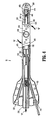
- Fig. 1 is a perspective view of a suturing device according to the present disclosure with a portion of the housing removed and with a ferrule assembly in a first position;
- Fig. 2 is a top, cross-sectional view of the suturing device of Fig. 1 ;
- Fig. 3 is an enlarged view of one end of the ferrule assembly of the suturing device of Fig. 1 ;
- Fig. 4 is a top view of the suturing device of Fig. 1 , with the ferrule assembly in a second position.
- proximal will refer to the end of the apparatus which is closest to the operator during use, while the term “distal” will refer to the end which is farthest from the operator, as is traditional.
- suturing device 10 is shown generally including a housing 100, a shaft 200, a head portion 300 and a ferrule assembly 400.
- Shaft 200 is attached at a proximal end 210 to housing 100 and at a distal end 220 to head portion 300.
- Ferrule assembly 400 is disposed on the shaft 200 and is configured to rotate between a first position and a second position with respect to shaft 200, as will be described in greater detail below.
- a manually manipulatable member, or plunger 250 is coupled to ferrule assembly 400 and is selectively translatable to rotate ferrule assembly 400 between the first and second positions.
- a suture passer, or needle 500 is configured for insertion through housing 100 via guide lumens 110, 120.
- Needle 500 includes a distal tip portion 510 and a lumen 520 extending at least partially therethrough.
- head portion 300 is disposed at a distal end 220 of shaft 200.
- Distal end 310 of head portion 300 may be generally conically shaped to facilitate the insertion of suturing device 10 through an opening in tissue and/or may include a blunt tip portion to help avoid damaging tissue upon insertion into an opening in tissue.
- Lumen 320 of head portion 300 is configured to releasably retain a portion of a suture 600 therein. As shown in Figs. 2 and 3 , both ends of suture 600 extend from lumen 320. More particularly, one end of suture 600 is attached to ferrule 435 ( Fig. 2 ) while the other end of suture 600 is attached to ferrule 445 ( Fig 3 ). Each ferrule 435, 445 is removably disposed in a respective ferrule lumen 432, 442 of a ferrule holder 430, 440 of rotating plate 410.
- Rotating plate 410 includes two ferrule holders 430, 440 disposed at opposite ends 412, 414 of rotating plate 410, respectively.
- Each ferrule holder 430, 440 includes a respective ferrule lumen 432, 442 for releasably retaining a ferrule 435, 445, respectively, therein.
- Ferrule lumens 432 and 442 extend through rotating plate 410, as shown in Figs. 1-3 . It is envisioned that rotating plate 410 may include more than two ferrule lumens extending therethrough and it is also contemplated that the ferrule lumens 432, 442 may be disposed at different positions along rotating plate 410.
- the ferrule holders 430, 440 may include any other suitable structure capable of releasably retaining a ferrule 435, 445 thereon.
- Rotating plate 410 further includes a central aperture 450 defined through a central portion 416 thereof.
- a pivot pin 452 is disposed through central aperture 450 of rotating plate 410 and is retained therethrough via nut 454 disposed on an opposide side of rotating plate 410.
- Pivot pin 452 is similarly disposed through an aperture (not explicitly shown) defined within shaft 200 thereby securing rotating plate 410 on shaft 200 such that rotating plate 410 may rotate about pivot pin 452 with respect to shaft 200, e.g., between first and second positions.
- Arm 460 includes first and second ends 462 and 464, respectively, which have apertures 463 and 465, respectively, defined therethrough. Pivot pin 466 connects first end 462 of arm 460 with rotating plate 410.
- pivot pin 466 is disposed through both aperture 463 of first end 462 of arm 460 and aperture 472 of end 412 of rotating plate 410 such that rotating plate 410 is rotatable with respect to arm 460 about pivot 466.
- pivot pin 468 connects second end 464 of arm 460 with bar 470 via apertures 465 and 474, respectively.
- Bar 470 is longitudinally translatable through conduit 130 of shaft 200, as will be discussed in greater detail below.
- plunger 250 is disposed at least partially through conduit 130 of housing 100.
- Conduit 130 extends distally from housing 100 through shaft 200.
- Proximal end 252 of plunger 250 extends proximally from housing 110 and is selectively depressible by an operator to translate plunger 250 distally through conduit 130 to the position shown in Fig. 4 .
- distal translation of plunger 250 i.e., when an operator depresses plunger 250, distal end 256 of plunger 250 repositions, or translates bar 470 distally.
- Spring 254 is configured to bias plunger 250 toward the position shown in Figs. 1 and 2 , e.g., a proximal-most position.
- the operator must overcome the biasing force of spring 254.
- rotating plate 410 is disposed in the first position, wherein base plate 410 is positioned substantially perpendicular to shaft 200 such that ferrule holders 430, 440 extend radially outward from shaft 200, as shown in Figs. 1-3 .
- This first position corresponds to the use position of suturing device 10, as will be described in greater detail below.
- plunger 250 When plunger 250 is depressed distally, e.g., in the direction of arrow "A,” as shown in Fig. 4 , bar 470 is urged distally through conduit 130 by distal tip 256 of plunger 250. Accordingly, arm 460, which is rotatably secured to bar 470 at second end 464 via pivot pin 468, is pulled distally in the direction of arrow "A" with respect to shaft 200. As arm 460 is pulled distally, rotating plate 410 is rotated in the direction of arrow "B" due to the pivotable connection of end 412 of rotating plate 410 with end 462 of arm 460. Upon further distal translation of plunger 250, and thus bar 470, rotating plate 410 is rotated to the position shown in Fig. 4 .
- suturing device 10 defines a minimum diameter to facilitate insertion through an opening in tissue. It is also contemplated that suturing device 10 include a locking mechanism (not shown) configured to lock rotating plate 410 in one or both of the first and second positions.
- suturing device 10 In preparation for suturing, a middle portion of suture 600 is retained within lumen 320 of head portion 300. One end of suture 600 is then attached to ferrule 435, while the other end of suture 600 is attached to ferrule 445. Next, ferrules 435 and 445 and loaded into the ferrule lumens 432 and 442 of ferrule holders 430 and 440, respectively, of ferrule assembly 400. At this point, suturing device 10 is configured, or loaded for use. Once suturing device 10 is loaded for use, plunger 250 may be depressed to rotate rotating plate 410 to the second, or insertion position, as shown in Fig. 4 such that suturing device 10 may then be inserted into an opening in tissue.
- Suturing device 10 is inserted, starting with head portion 300, through an opening (wound) in tissue that is to be sutured.
- the suturing device 10 is translated through the wound until the ferrule assembly 400 is disposed adjacent an interior surface of tissue to be sutured.
- plunger 250 may be released, thereby allowing plunger 250 and, thus bar 470, to translate proximally back to the first, or at-rest position, e.g., the use position, as shown in Figs. 1 and 2 .
- rotatable plate 410 is rotated to the first position such that ferrule lumen 432 of ferrule holder 430, which houses ferrule 435, is disposed adjacent a first side of the wound and such that ferrule lumen 442 of ferrule holder 440, which houses ferrule 445, is disposed adjacent an opposite side of the wound.
- a length of rotating plate 410 be configured according to the diameter of wound to be sutured.
- rotating plate 410 and arm 460 are removable from suturing device 10 such that an operator may select a rotatable plate and corresponding arm having a length sufficient to allow the ferrule holders 430, 440 to be disposed on either side of the wound when in the first position.
- needle 500 is inserted through guide lumen 120 of housing 100, as shown in Figs. 1 and 2 .
- guide lumen 120 directs needle 500 through tissue and toward ferrule 445 due to the alignment of guide lumen 120 and ferrule holder 440, when ferrule assembly 400 is in the first position.
- distal tip 510 of needle 500 passes completely through tissue and eventually enters ferrule lumen 442 of ferrule holder 440.
- needle 500 surrounds ferrule 445 such that ferrule 445 is disposed through lumen 520 of needle 500.
- Lumen 520 may have a slightly smaller diameter than ferrule 445 such that when needle 500 is urged around ferrule 445, ferrule 445 becomes lodged within lumen 520, fixedly retaining ferrule 445 therein via a male-female friction-fit engagement.
- lumen 520 may taper proximally from distal tip 510 from a first diameter which is larger than the diameter of ferrule 445 to a second diameter which is smaller than the diameter of ferrule 445.
- needle 500 may define a sufficiently small diameter to engage a lumen (not shown) defined in ferrule 445.
- needle 500 may be urged into the lumen defined in ferrule 445 such that the ferrule 445 and needle 500 are engaged in a male-female friction-fit engagement.
- any of the above-mentioned configurations of needle 500 and ferrule 445 may be similarly used with respect to ferrule 435 and/or a different suture passer 500. It is also envisioned that other suitable mechanisms or configurations for engaging needle 500 and ferrules 435, 445 may be provided.
- needle 500 may be pulled proximally, or retracted from ferrule holder 440. As needle 500 is pulled further proximally back through tissue, ferrule 445 is removed from ferrule lumen 442. Needle 500 and, thus, ferrule 445 and suture 600, are translated proximally through tissue until needle 500 and ferrule 445 have passed completely through tissue, leaving suture 600 disposed through tissue on one side of the wound. More specifically, the end of suture 600 engaged to ferrule 445 extends proximally through tissue, while the middle portion of suture 600 remains disposed within head assembly 300, which is disposed within tissue, i.e., on a distal side of tissue. Needle 500 is then removed from guide lumen 120 and ferrule 445 is separated from needle 500.
- needle 500 or a new needle substantially similar to needle 500, is inserted into guide lumen 110 of housing 100.
- Guide lumen 110 directs needle 500 through tissue on the opposing side of the wound and toward ferrule holder 430.
- needle 500 is then translated further through ferrule lumen 432 of ferrule holder 440 to engage ferrule 435 therein in a male-female friction-fit engagement.
- Needle 500 and ferrule 435 are then translated proximally back through tissue, as described above, such that suture 600 is disposed through tissue on an opposing side of the wound. Needle 500 may then be removed from the wound and plunger 250 may be depressed to rotate rotating plate 410 to the second position, as described above.
- Suturing instrument 10 may then be removed from the wound, leaving suture 600 disposed through tissue on both sides of the wound with the middle portion of suture 600 interconnecting the ends thereof on a distal, or internal side of tissue.
- Head assembly 300 may be configured to release suture 600 therefrom upon removal of suturing instrument 10 from the wound in tissue, or suture 600 may be manually released from head assembly 300 upon removal of suturing instrument 10. Once suturing instrument 10 has been removed, the operator can then tighten and tie off the free ends of suture 600 to close the wound.
Abstract
Description
- The present application claims the benefit of and priority to
U.S. Provisional Application Serial. No. 61/247,650 filed on October 1, 2009 - The present disclosure relates to a wound closure device and, more particularly, to a wound closure device having a ferrule ejector system for suturing a wound.
- Puncture wounds, wounds that pierce through tissue, may result from trauma or may be intentionally created in order to provide access to a body cavity during surgical procedures. During endoscopic surgical procedures, for example, a trocar device is utilized to puncture the peritoneum to provide an access port by way of a cannula through the abdominal wall. Generally, a trocar and/or cannula is placed through the abdominal wall for introduction of surgical instrumentation which is necessary to carry out the surgical procedure. In this manner, the surgeon may introduce a surgical instrument such as a grasper, scissor, clip applier, stapler or any other surgical instrument which may be necessary during the particular surgical procedure. Once the procedure is complete, it is necessary to suture the wound.
- Conventional instruments for closing puncture wounds generally include a shaft that can be extended into the body through either the puncture wound itself (in the case of a puncture caused by trauma) or through a cannula (in the case of a puncture created to access a surgical site). Suture retaining needles are then deployed from the shaft into tissue. Unfortunately, the mechanisms used for deploying the needles are often cumbersome and may make the extension and/or retraction of the suturing device difficult.
- In the prior art,
U.S. Patent No. 5,470,330 discloses a suturing instrument for closing trocar puncture wounds. The suturing instrument includes a pair of needle carriers having needles releasably retained thereon. The needle carriers are translatable from a retracted position to a deployed position to urge the needles into tissue.U.S. Patent No. 6,296,640 discloses a suturing aid including one or more vanes that are moveable from a first position, wherein the vanes are folded up proximally for insertion, to a second position, wherein the vanes are swung out laterally to help align a suturing instrument, and, finally, to a third position, wherein the vanes are folded up distally for removal.U.S. Patent No. 6,911,034 discloses a suturing apparatus including one or more arms having a suture mounting portion and one or more needles. Each arm is extendable from the apparatus to penetrate tissue, while each needle is advanceable to a position adjacent an arm to capture the suture mounted thereon and to draw the suture back toward the suturing apparatus.U.S. Patent No. 7,235,087 discloses an articulating suturing device having an articulating foot. The foot includes suture attachment cuffs configured to engage needles for withdrawing the cuffs through tissue.U.S. Patent No. 7,449,024 discloses a suturing device having arms that are extendable from the suturing device. Needles may then be advanced into engagement with the arms to retrieve a suture from the arms.U.S. Patent Application Publication No. 2006/0030868 discloses a suturing device including a pair of wings that are selectively extendable from the device. Needles carrying sutures thereon may then be advanced through tissue and into engagement with the wings to retain the sutures thereon.U.S. Patent Application Publication Nos. 2008/0045979 and2009/0157105 disclose articulating suture devices similar to that disclosed inU.S. Patent No. 7,235,087 , discussed above. - In accordance with the present disclosure, a suturing device is provided. The suturing device includes a housing having a shaft attached thereto and one or more guide lumens extending therethrough. The shaft includes a head portion disposed at a distal end thereof. The head portion is configured to retain a portion of a suture therein. A ferrule assembly is rotatably coupled to the shaft and includes one or more ferrule holders each of which is configured to releasably retain a ferrule therein. Each ferrule is configured to retain a portion of the suture thereon. The ferrule assembly is rotatable with respect to the shaft between a first position and a second position. Each guide lumen is configured to direct a suture passer inserted therethrough into engagement with the ferrule of one of the ferrule holders when the ferrule assembly is disposed in the first position.
- In one embodiment, the suturing device further includes a manually manipulatable member operably coupled to the ferrule assembly. The manually manipulatable member is configured to rotate the ferrule assembly between the first and second positions.
- The ferrule assembly may be positioned substantially perpendicular to the shaft when in the first position such that the ferrule holders are radially spaced from the shaft when in the first position. Further, the ferrule assembly may be positioned substantially parallel to the shaft when in the second position such that the ferrule holders are disposed within an outer diameter of the shaft when in the second position.
- In another embodiment, the suture passer includes a needle configured to engage the ferrule in a female-male friction fit engagement.
- In yet another embodiment, the ferrule assembly includes a rotatable plate having first and second ferrule holders disposed at first and second ends, respectively, thereof. The first and second ferrule holders may be configured for positioning on opposite sides of a wound in tissue when moved to the first position.
- In still yet another embodiment, the ferrule assembly is biased toward the first position.
- Various embodiments of the subject instrument are described herein with reference to the drawings wherein:
-
Fig. 1 is a perspective view of a suturing device according to the present disclosure with a portion of the housing removed and with a ferrule assembly in a first position; -
Fig. 2 is a top, cross-sectional view of the suturing device ofFig. 1 ; -
Fig. 3 is an enlarged view of one end of the ferrule assembly of the suturing device ofFig. 1 ; and -
Fig. 4 is a top view of the suturing device ofFig. 1 , with the ferrule assembly in a second position. - In the figures and in the description that follows, in which like reference numerals identify similar or identical elements, the term "proximal" will refer to the end of the apparatus which is closest to the operator during use, while the term "distal" will refer to the end which is farthest from the operator, as is traditional.
- Referring now to
Figs. 1-4 , suturingdevice 10 is shown generally including ahousing 100, ashaft 200, ahead portion 300 and aferrule assembly 400.Shaft 200 is attached at aproximal end 210 to housing 100 and at adistal end 220 tohead portion 300.Ferrule assembly 400 is disposed on theshaft 200 and is configured to rotate between a first position and a second position with respect toshaft 200, as will be described in greater detail below. A manually manipulatable member, orplunger 250, is coupled toferrule assembly 400 and is selectively translatable to rotateferrule assembly 400 between the first and second positions. A suture passer, orneedle 500, is configured for insertion throughhousing 100 viaguide lumens guide lumen needle 500 toward acorresponding ferrule holder rotating plate 410 offerrule assembly 400 whenferrule assembly 400 is disposed in the second position.Needle 500 includes adistal tip portion 510 and alumen 520 extending at least partially therethrough. - As mentioned above,
head portion 300 is disposed at adistal end 220 ofshaft 200.Distal end 310 ofhead portion 300 may be generally conically shaped to facilitate the insertion of suturingdevice 10 through an opening in tissue and/or may include a blunt tip portion to help avoid damaging tissue upon insertion into an opening in tissue.Lumen 320 ofhead portion 300 is configured to releasably retain a portion of asuture 600 therein. As shown inFigs. 2 and 3 , both ends ofsuture 600 extend fromlumen 320. More particularly, one end ofsuture 600 is attached to ferrule 435 (Fig. 2 ) while the other end ofsuture 600 is attached to ferrule 445 (Fig 3 ). Eachferrule respective ferrule lumen ferrule holder rotating plate 410. - Rotating
plate 410 includes twoferrule holders rotating plate 410, respectively. Eachferrule holder respective ferrule lumen ferrule Ferrule lumens rotating plate 410, as shown inFigs. 1-3 . It is envisioned that rotatingplate 410 may include more than two ferrule lumens extending therethrough and it is also contemplated that theferrule lumens plate 410. Alternatively, theferrule holders ferrule - Rotating
plate 410 further includes acentral aperture 450 defined through acentral portion 416 thereof. Apivot pin 452 is disposed throughcentral aperture 450 ofrotating plate 410 and is retained therethrough vianut 454 disposed on an opposide side of rotatingplate 410.Pivot pin 452 is similarly disposed through an aperture (not explicitly shown) defined withinshaft 200 thereby securingrotating plate 410 onshaft 200 such thatrotating plate 410 may rotate aboutpivot pin 452 with respect toshaft 200, e.g., between first and second positions.Arm 460 includes first and second ends 462 and 464, respectively, which haveapertures Pivot pin 466 connectsfirst end 462 ofarm 460 withrotating plate 410. More particularly,pivot pin 466 is disposed through bothaperture 463 offirst end 462 ofarm 460 andaperture 472 ofend 412 ofrotating plate 410 such thatrotating plate 410 is rotatable with respect toarm 460 aboutpivot 466. Similarly,pivot pin 468 connectssecond end 464 ofarm 460 withbar 470 viaapertures Bar 470 is longitudinally translatable throughconduit 130 ofshaft 200, as will be discussed in greater detail below. - As shown in
Figs. 1-4 ,plunger 250 is disposed at least partially throughconduit 130 ofhousing 100.Conduit 130 extends distally fromhousing 100 throughshaft 200.Proximal end 252 ofplunger 250 extends proximally fromhousing 110 and is selectively depressible by an operator to translateplunger 250 distally throughconduit 130 to the position shown inFig. 4 . Upon distal translation ofplunger 250, i.e., when an operator depressesplunger 250,distal end 256 ofplunger 250 repositions, or translatesbar 470 distally.Spring 254 is configured to biasplunger 250 toward the position shown inFigs. 1 and2 , e.g., a proximal-most position. Thus, in order to depressplunger 250 and translatebar 470 distally, the operator must overcome the biasing force ofspring 254. - Initially, when
plunger 250 is disposed in an at-rest, or proximal-most position, rotatingplate 410 is disposed in the first position, whereinbase plate 410 is positioned substantially perpendicular toshaft 200 such thatferrule holders shaft 200, as shown inFigs. 1-3 . This first position corresponds to the use position of suturingdevice 10, as will be described in greater detail below. - When
plunger 250 is depressed distally, e.g., in the direction of arrow "A," as shown inFig. 4 ,bar 470 is urged distally throughconduit 130 bydistal tip 256 ofplunger 250. Accordingly,arm 460, which is rotatably secured to bar 470 atsecond end 464 viapivot pin 468, is pulled distally in the direction of arrow "A" with respect toshaft 200. Asarm 460 is pulled distally, rotatingplate 410 is rotated in the direction of arrow "B" due to the pivotable connection ofend 412 ofrotating plate 410 withend 462 ofarm 460. Upon further distal translation ofplunger 250, and thus bar 470, rotatingplate 410 is rotated to the position shown inFig. 4 . In this second position, rotatingplate 410 is aligned withshaft 200 such thatrotating plate 410 does not extend beyond the dimensions ofshaft 200, i.e., such thatrotating plate 410 is positioned substantially parallel with respect toshaft 200. As such, in this second position, or insertion position, suturingdevice 10 defines a minimum diameter to facilitate insertion through an opening in tissue. It is also contemplated that suturingdevice 10 include a locking mechanism (not shown) configured to lockrotating plate 410 in one or both of the first and second positions. - In preparation for suturing, a middle portion of
suture 600 is retained withinlumen 320 ofhead portion 300. One end ofsuture 600 is then attached toferrule 435, while the other end ofsuture 600 is attached toferrule 445. Next,ferrules ferrule lumens ferrule holders ferrule assembly 400. At this point, suturingdevice 10 is configured, or loaded for use. Once suturingdevice 10 is loaded for use,plunger 250 may be depressed to rotaterotating plate 410 to the second, or insertion position, as shown inFig. 4 such thatsuturing device 10 may then be inserted into an opening in tissue. -
Suturing device 10 is inserted, starting withhead portion 300, through an opening (wound) in tissue that is to be sutured. Thesuturing device 10 is translated through the wound until theferrule assembly 400 is disposed adjacent an interior surface of tissue to be sutured. Once positioned accordingly,plunger 250 may be released, thereby allowingplunger 250 and, thus bar 470, to translate proximally back to the first, or at-rest position, e.g., the use position, as shown inFigs. 1 and2 . More specifically, asbar 470 is translated proximally,rotatable plate 410 is rotated to the first position such thatferrule lumen 432 offerrule holder 430, which housesferrule 435, is disposed adjacent a first side of the wound and such thatferrule lumen 442 offerrule holder 440, which housesferrule 445, is disposed adjacent an opposite side of the wound. Thus, it is envisioned that a length of rotatingplate 410 be configured according to the diameter of wound to be sutured. It is also envisioned that rotatingplate 410 andarm 460 are removable from suturingdevice 10 such that an operator may select a rotatable plate and corresponding arm having a length sufficient to allow theferrule holders - Continuing with the operation of
suturing device 10, onceferrule assembly 400 is inserted through the wound in tissue and is moved back to the first position, whereinferrule holders ferrule lumens needle 500 is inserted throughguide lumen 120 ofhousing 100, as shown inFigs. 1 and2 . Asneedle 500 is translated distally throughguide lumen 120,guide lumen 120 directsneedle 500 through tissue and towardferrule 445 due to the alignment ofguide lumen 120 andferrule holder 440, whenferrule assembly 400 is in the first position. Upon further distal translation ofneedle 500,distal tip 510 ofneedle 500 passes completely through tissue and eventually entersferrule lumen 442 offerrule holder 440. Asneedle 500 is urged distally intolumen 442,needle 500 surroundsferrule 445 such thatferrule 445 is disposed throughlumen 520 ofneedle 500.Lumen 520 may have a slightly smaller diameter thanferrule 445 such that whenneedle 500 is urged aroundferrule 445,ferrule 445 becomes lodged withinlumen 520, fixedly retainingferrule 445 therein via a male-female friction-fit engagement. Alternatively,lumen 520 may taper proximally fromdistal tip 510 from a first diameter which is larger than the diameter offerrule 445 to a second diameter which is smaller than the diameter offerrule 445. In this configuration, further urging ofneedle 500 aroundferrule 445 engagesferrule 445 withinlumen 520 in a male-female friction-fit engagement. In another alternative embodiment,needle 500 may define a sufficiently small diameter to engage a lumen (not shown) defined inferrule 445. In this embodiment,needle 500 may be urged into the lumen defined inferrule 445 such that theferrule 445 andneedle 500 are engaged in a male-female friction-fit engagement. While described with reference toferrule 445, it is envisioned that any of the above-mentioned configurations ofneedle 500 andferrule 445 may be similarly used with respect toferrule 435 and/or adifferent suture passer 500. It is also envisioned that other suitable mechanisms or configurations for engagingneedle 500 andferrules - Once
ferrule 445 is retained withinlumen 520 ofneedle 500,needle 500 may be pulled proximally, or retracted fromferrule holder 440. Asneedle 500 is pulled further proximally back through tissue,ferrule 445 is removed fromferrule lumen 442.Needle 500 and, thus,ferrule 445 andsuture 600, are translated proximally through tissue untilneedle 500 andferrule 445 have passed completely through tissue, leavingsuture 600 disposed through tissue on one side of the wound. More specifically, the end ofsuture 600 engaged toferrule 445 extends proximally through tissue, while the middle portion ofsuture 600 remains disposed withinhead assembly 300, which is disposed within tissue, i.e., on a distal side of tissue.Needle 500 is then removed fromguide lumen 120 andferrule 445 is separated fromneedle 500. - Next,
needle 500, or a new needle substantially similar toneedle 500, is inserted intoguide lumen 110 ofhousing 100.Guide lumen 110 directsneedle 500 through tissue on the opposing side of the wound and towardferrule holder 430. Similarly as described above,needle 500 is then translated further throughferrule lumen 432 offerrule holder 440 to engageferrule 435 therein in a male-female friction-fit engagement.Needle 500 andferrule 435 are then translated proximally back through tissue, as described above, such thatsuture 600 is disposed through tissue on an opposing side of the wound.Needle 500 may then be removed from the wound andplunger 250 may be depressed to rotaterotating plate 410 to the second position, as described above. Suturinginstrument 10 may then be removed from the wound, leavingsuture 600 disposed through tissue on both sides of the wound with the middle portion ofsuture 600 interconnecting the ends thereof on a distal, or internal side of tissue.Head assembly 300 may be configured to releasesuture 600 therefrom upon removal of suturinginstrument 10 from the wound in tissue, orsuture 600 may be manually released fromhead assembly 300 upon removal of suturinginstrument 10. Once suturinginstrument 10 has been removed, the operator can then tighten and tie off the free ends ofsuture 600 to close the wound. - From the foregoing and with reference to the various figure drawings, those skilled in the art will appreciate that certain modifications can also .be made to the present disclosure without departing from the scope of the same. While several embodiments of the disclosure have been shown in the drawings, it is not intended that the disclosure be limited thereto, as it is intended that the disclosure be as broad in scope as the art will allow and that the specification be read likewise. Therefore, the above description should not be construed as limiting, but merely as exemplifications of particular embodiments. Those skilled in the art will envision other modifications within the scope and spirit of the claims appended hereto.
Claims (8)
- A suturing device, comprising:a housing having a shaft attached thereto and defining at least one guide lumen extending therethrough, the shaft having a head portion disposed at a distal end thereof, the head portion configured to retain a portion of a suture therein; anda ferrule assembly rotatably coupled to the shaft, the ferrule assembly including at least one ferrule holder disposed thereon, each ferrule holder being configured to releasably retain a ferrule therein, each ferrule being configured to retain a portion of the suture thereon, the ferrule assembly being rotatable with respect to the shaft between a first position and a second position, wherein the at least one guide lumen is configured to direct a suture passer inserted therethrough into engaged with the ferrule of one of the ferrule holders when the ferrule assembly is disposed in one of the first and second positions.
- The suturing device of claim 1, wherein the housing further includes a manually manipulatable member operably coupled to the ferrule assembly, the manually manipulatable member configured to rotate the ferrule assembly between the first and second positions.
- The suturing device according to claim 1 or claim 2, wherein the ferrule assembly is positioned substantially perpendicular to the shaft when in the first position such that the ferrule holders are radially spaced from the shaft when in the first position.
- The suturing device according to claim 1 or claim 2, wherein the ferrule assembly is positioned substantially parallel to the shaft when in the second position such that the ferrule holders are disposed within an outer diameter of the shaft when in the second position.
- The suturing device according to any preceding claim, wherein the suture passer comprises a needle configured to engage the ferrule in a female-male friction fit engagement.
- The suturing device according to any preceding claim, wherein the ferrule assembly includes a rotatable plate having first and second ferrule holders disposed at first and second ends thereof.
- The suturing device according to claim 6, wherein the first and second ferrule holders are positionable on opposite sides of a wound when moved to the first position.
- The suturing device according to any preceding claim, wherein the ferrule assembly is biased toward the first position.
Applications Claiming Priority (2)
| Application Number | Priority Date | Filing Date | Title |
|---|---|---|---|
| US24765009P | 2009-10-01 | 2009-10-01 | |
| US12/887,766 US20110082475A1 (en) | 2009-10-01 | 2010-09-22 | Wound closure device including ferrule ejector system |
Publications (2)
| Publication Number | Publication Date |
|---|---|
| EP2305129A2 true EP2305129A2 (en) | 2011-04-06 |
| EP2305129A3 EP2305129A3 (en) | 2013-05-15 |
Family
ID=43498603
Family Applications (1)
| Application Number | Title | Priority Date | Filing Date |
|---|---|---|---|
| EP10251691.1A Withdrawn EP2305129A3 (en) | 2009-10-01 | 2010-09-30 | Wound closure device including ferrule ejector systeme |
Country Status (5)
| Country | Link |
|---|---|
| US (1) | US20110082475A1 (en) |
| EP (1) | EP2305129A3 (en) |
| JP (1) | JP2011072794A (en) |
| AU (1) | AU2010226926A1 (en) |
| CA (1) | CA2716029A1 (en) |
Cited By (5)
| Publication number | Priority date | Publication date | Assignee | Title |
|---|---|---|---|---|
| WO2013103682A2 (en) * | 2012-01-04 | 2013-07-11 | Teleflex Medical Incorporated | Apparatus and methods for tissue closure |
| WO2013101730A3 (en) * | 2011-12-27 | 2013-10-17 | Coopersurgical, Inc. | Suture passer guides and related kits |
| US8979747B2 (en) | 2011-09-23 | 2015-03-17 | Cooper Surgicalk, Inc. | Endoscopic ports and related kits and methods |
| US9066717B2 (en) | 2012-05-18 | 2015-06-30 | Coopersurgical, Inc. | Suture passer guides and related kits and methods |
| US9636105B2 (en) | 2009-01-12 | 2017-05-02 | Teleflex Medical Incorporated | Apparatus and methods for tissue closure |
Families Citing this family (21)
| Publication number | Priority date | Publication date | Assignee | Title |
|---|---|---|---|---|
| US8906042B2 (en) | 2010-07-29 | 2014-12-09 | Covidien Lp | Wound closure device including mesh barrier |
| US20130035699A1 (en) * | 2011-08-04 | 2013-02-07 | Suture Ease, LLC | Dual insufflation and wound closure devices and methods |
| EP2825101A4 (en) | 2012-03-13 | 2015-12-16 | Suture Ease Llc | Needle and snare guide apparatus for passing suture |
| US9271708B2 (en) | 2013-03-13 | 2016-03-01 | Medtronic Vascular, Inc. | Suturing device and method for sealing an opening in a blood vessel or other biological structure |
| US9095319B2 (en) * | 2013-03-13 | 2015-08-04 | Medtronic Vascular, Inc. | Suturing device and method for sealing an opening in a blood vessel or other biological structure |
| US9510823B2 (en) | 2013-08-02 | 2016-12-06 | Covidien Lp | Devices, systems, and methods for wound closure |
| US9681868B2 (en) | 2013-08-02 | 2017-06-20 | Covidien Lp | Devices, systems, and methods for wound closure |
| US9918712B2 (en) * | 2013-08-02 | 2018-03-20 | Covidien Lp | Devices, systems, and methods for providing surgical access and facilitating closure of surgical access openings |
| US10070851B2 (en) | 2013-08-02 | 2018-09-11 | Covidien Lp | Devices, systems, and methods for wound closure |
| US9554781B2 (en) * | 2014-01-23 | 2017-01-31 | Lsi Solutions, Inc. | Minimally invasive surgical suturing device and method |
| CA2938858C (en) | 2014-02-07 | 2022-08-30 | Medeon Biodesign, Inc. | Suture delivery device for suturing tissue |
| US10327761B2 (en) | 2014-02-07 | 2019-06-25 | Medeon Biodesign, Inc. | Suture delivery device for suturing tissue |
| KR101591056B1 (en) * | 2014-11-21 | 2016-02-18 | 김기성 | sewing cotton for laparoscopic port site closure device |
| KR101594082B1 (en) * | 2014-11-21 | 2016-02-15 | 김기성 | Laparoscopic port site closure device |
| US10299785B2 (en) * | 2016-04-01 | 2019-05-28 | Ethicon Llc | Surgical access devices with integrated wound closure features |
| CN110213996B (en) * | 2016-08-11 | 2022-08-30 | 益安生医股份有限公司 | Suture delivery device for suturing tissue |
| US11026676B2 (en) | 2017-02-06 | 2021-06-08 | Covidien Lp | Surgical wound closure apparatus |
| US10939937B2 (en) * | 2017-06-29 | 2021-03-09 | Ethicon Llc | Trocar with oblique needle insertion port and perpendicular seal latch |
| US11129609B2 (en) | 2018-04-24 | 2021-09-28 | Covidien Lp | Devices, systems, and methods for providing surgical access and facilitating closure of surgical access openings |
| US11234690B2 (en) | 2018-05-02 | 2022-02-01 | Covidien Lp | Method and device for closing a port site incision |
| US11213288B2 (en) * | 2018-05-02 | 2022-01-04 | Covidien Lp | Port site closure instrument |
Citations (8)
| Publication number | Priority date | Publication date | Assignee | Title |
|---|---|---|---|---|
| US5470330A (en) | 1984-12-07 | 1995-11-28 | Advanced Interventional Systems, Inc. | Guidance and delivery system for high-energy pulsed laser light |
| US6296640B1 (en) | 1998-02-06 | 2001-10-02 | Ethicon Endo-Surgery, Inc. | RF bipolar end effector for use in electrosurgical instruments |
| US6911034B2 (en) | 2000-06-14 | 2005-06-28 | Sterilis, Inc. | Suturing method and apparatus |
| US20060030868A1 (en) | 2004-08-05 | 2006-02-09 | Bennett Richard M Iii | Laparoscopic port site closure tool |
| US7235087B2 (en) | 1999-03-04 | 2007-06-26 | Abbott Park | Articulating suturing device and method |
| US20080045979A1 (en) | 2006-08-18 | 2008-02-21 | Abbott Laboratories | Articulating suture device and method |
| US7449024B2 (en) | 2003-12-23 | 2008-11-11 | Abbott Laboratories | Suturing device with split arm and method of suturing tissue |
| US20090157105A1 (en) | 1999-03-04 | 2009-06-18 | Abbott Laboratories | Articulating suturing device and method |
Family Cites Families (4)
| Publication number | Priority date | Publication date | Assignee | Title |
|---|---|---|---|---|
| US5470338A (en) * | 1993-10-08 | 1995-11-28 | United States Surgical Corporation | Instrument for closing trocar puncture wounds |
| US6562052B2 (en) * | 1995-08-24 | 2003-05-13 | Sutura, Inc. | Suturing device and method |
| EP0902649B1 (en) * | 1996-05-10 | 2001-09-05 | Karl Storz GmbH & Co. KG | Suturing aid |
| EP1804677B1 (en) * | 2004-09-27 | 2018-01-03 | Nobles Medical Technologies, Inc. | Handle for suturing apparatus |
-
2010
- 2010-09-22 US US12/887,766 patent/US20110082475A1/en not_active Abandoned
- 2010-09-30 CA CA2716029A patent/CA2716029A1/en not_active Abandoned
- 2010-09-30 JP JP2010223267A patent/JP2011072794A/en active Pending
- 2010-09-30 EP EP10251691.1A patent/EP2305129A3/en not_active Withdrawn
- 2010-10-01 AU AU2010226926A patent/AU2010226926A1/en not_active Abandoned
Patent Citations (8)
| Publication number | Priority date | Publication date | Assignee | Title |
|---|---|---|---|---|
| US5470330A (en) | 1984-12-07 | 1995-11-28 | Advanced Interventional Systems, Inc. | Guidance and delivery system for high-energy pulsed laser light |
| US6296640B1 (en) | 1998-02-06 | 2001-10-02 | Ethicon Endo-Surgery, Inc. | RF bipolar end effector for use in electrosurgical instruments |
| US7235087B2 (en) | 1999-03-04 | 2007-06-26 | Abbott Park | Articulating suturing device and method |
| US20090157105A1 (en) | 1999-03-04 | 2009-06-18 | Abbott Laboratories | Articulating suturing device and method |
| US6911034B2 (en) | 2000-06-14 | 2005-06-28 | Sterilis, Inc. | Suturing method and apparatus |
| US7449024B2 (en) | 2003-12-23 | 2008-11-11 | Abbott Laboratories | Suturing device with split arm and method of suturing tissue |
| US20060030868A1 (en) | 2004-08-05 | 2006-02-09 | Bennett Richard M Iii | Laparoscopic port site closure tool |
| US20080045979A1 (en) | 2006-08-18 | 2008-02-21 | Abbott Laboratories | Articulating suture device and method |
Cited By (12)
| Publication number | Priority date | Publication date | Assignee | Title |
|---|---|---|---|---|
| US9636105B2 (en) | 2009-01-12 | 2017-05-02 | Teleflex Medical Incorporated | Apparatus and methods for tissue closure |
| US10485533B2 (en) | 2009-01-12 | 2019-11-26 | Teleflex Medical Incorporated | Apparatus and methods for tissue closure |
| US11666324B2 (en) | 2009-01-12 | 2023-06-06 | Teleflex Medical Incorporated | Apparatus and methods for tissue closure |
| US8979747B2 (en) | 2011-09-23 | 2015-03-17 | Cooper Surgicalk, Inc. | Endoscopic ports and related kits and methods |
| WO2013101730A3 (en) * | 2011-12-27 | 2013-10-17 | Coopersurgical, Inc. | Suture passer guides and related kits |
| US9149272B2 (en) | 2011-12-27 | 2015-10-06 | Coopersurgical, Inc. | Suture passer guides and related kits and methods |
| WO2013103682A2 (en) * | 2012-01-04 | 2013-07-11 | Teleflex Medical Incorporated | Apparatus and methods for tissue closure |
| WO2013103682A3 (en) * | 2012-01-04 | 2013-10-31 | Teleflex Medical Incorporated | Apparatus for tissue closure |
| US9782163B2 (en) | 2012-01-04 | 2017-10-10 | Teleflex Medical Incorporated | Apparatus and methods for tissue closure |
| EP2800521B1 (en) * | 2012-01-04 | 2020-03-04 | Teleflex Medical Incorporated | Apparatus for tissue closure |
| US10695051B2 (en) | 2012-01-04 | 2020-06-30 | Teleflex Medical Incorporated | Apparatus and methods for tissue closure |
| US9066717B2 (en) | 2012-05-18 | 2015-06-30 | Coopersurgical, Inc. | Suture passer guides and related kits and methods |
Also Published As
| Publication number | Publication date |
|---|---|
| EP2305129A3 (en) | 2013-05-15 |
| CA2716029A1 (en) | 2011-04-01 |
| AU2010226926A1 (en) | 2011-04-21 |
| US20110082475A1 (en) | 2011-04-07 |
| JP2011072794A (en) | 2011-04-14 |
Similar Documents
| Publication | Publication Date | Title |
|---|---|---|
| EP2305129A2 (en) | Wound closure device including ferrule ejector systeme | |
| US10631855B2 (en) | Wound closure device including direct-driven needle | |
| US9687226B2 (en) | Wound closure device including mesh barrier | |
| US6743241B2 (en) | Laparoscopic port site fascial closure device | |
| EP2308378A2 (en) | Wound closure device including releasable barbs | |
| US10058324B2 (en) | Suture device | |
| EP3563775B1 (en) | Port site closure instrument | |
| US8968341B2 (en) | Wound closure device |
Legal Events
| Date | Code | Title | Description |
|---|---|---|---|
| PUAI | Public reference made under article 153(3) epc to a published international application that has entered the european phase |
Free format text: ORIGINAL CODE: 0009012 |
|
| AK | Designated contracting states |
Kind code of ref document: A2 Designated state(s): AL AT BE BG CH CY CZ DE DK EE ES FI FR GB GR HR HU IE IS IT LI LT LU LV MC MK MT NL NO PL PT RO SE SI SK SM TR |
|
| AX | Request for extension of the european patent |
Extension state: BA ME RS |
|
| RAP1 | Party data changed (applicant data changed or rights of an application transferred) |
Owner name: COVIDIEN LP |
|
| PUAL | Search report despatched |
Free format text: ORIGINAL CODE: 0009013 |
|
| AK | Designated contracting states |
Kind code of ref document: A3 Designated state(s): AL AT BE BG CH CY CZ DE DK EE ES FI FR GB GR HR HU IE IS IT LI LT LU LV MC MK MT NL NO PL PT RO SE SI SK SM TR |
|
| AX | Request for extension of the european patent |
Extension state: BA ME RS |
|
| RIC1 | Information provided on ipc code assigned before grant |
Ipc: A61B 17/04 20060101AFI20130409BHEP Ipc: A61B 17/00 20060101ALI20130409BHEP |
|
| STAA | Information on the status of an ep patent application or granted ep patent |
Free format text: STATUS: THE APPLICATION IS DEEMED TO BE WITHDRAWN |
|
| 18D | Application deemed to be withdrawn |
Effective date: 20131116 |