EP2305985A2 - Containment casing for an aero engine - Google Patents
Containment casing for an aero engine Download PDFInfo
- Publication number
- EP2305985A2 EP2305985A2 EP10173514A EP10173514A EP2305985A2 EP 2305985 A2 EP2305985 A2 EP 2305985A2 EP 10173514 A EP10173514 A EP 10173514A EP 10173514 A EP10173514 A EP 10173514A EP 2305985 A2 EP2305985 A2 EP 2305985A2
- Authority
- EP
- European Patent Office
- Prior art keywords
- fan
- containment
- assembly according
- containment assembly
- casing
- Prior art date
- Legal status (The legal status is an assumption and is not a legal conclusion. Google has not performed a legal analysis and makes no representation as to the accuracy of the status listed.)
- Granted
Links
- 239000012634 fragment Substances 0.000 claims abstract description 38
- 239000000463 material Substances 0.000 claims description 16
- 230000033001 locomotion Effects 0.000 claims description 7
- 238000007789 sealing Methods 0.000 claims description 6
- 230000035939 shock Effects 0.000 claims description 2
- 229920000271 Kevlar® Polymers 0.000 description 9
- 239000004761 kevlar Substances 0.000 description 9
- 238000013459 approach Methods 0.000 description 5
- 239000004411 aluminium Substances 0.000 description 3
- 229910052782 aluminium Inorganic materials 0.000 description 3
- XAGFODPZIPBFFR-UHFFFAOYSA-N aluminium Chemical compound [Al] XAGFODPZIPBFFR-UHFFFAOYSA-N 0.000 description 3
- 239000002131 composite material Substances 0.000 description 3
- 229920000784 Nomex Polymers 0.000 description 2
- 229910001069 Ti alloy Inorganic materials 0.000 description 2
- 238000000034 method Methods 0.000 description 2
- 239000004763 nomex Substances 0.000 description 2
- 230000000717 retained effect Effects 0.000 description 2
- 229910000831 Steel Inorganic materials 0.000 description 1
- 230000033228 biological regulation Effects 0.000 description 1
- 230000015556 catabolic process Effects 0.000 description 1
- 238000006731 degradation reaction Methods 0.000 description 1
- 238000010586 diagram Methods 0.000 description 1
- 230000000694 effects Effects 0.000 description 1
- 239000006260 foam Substances 0.000 description 1
- 239000006261 foam material Substances 0.000 description 1
- 230000014759 maintenance of location Effects 0.000 description 1
- 229910052751 metal Inorganic materials 0.000 description 1
- 239000002184 metal Substances 0.000 description 1
- 230000000149 penetrating effect Effects 0.000 description 1
- 230000035515 penetration Effects 0.000 description 1
- ISWSIDIOOBJBQZ-UHFFFAOYSA-N phenol group Chemical group C1(=CC=CC=C1)O ISWSIDIOOBJBQZ-UHFFFAOYSA-N 0.000 description 1
- 229910001256 stainless steel alloy Inorganic materials 0.000 description 1
- 239000010959 steel Substances 0.000 description 1
- 238000011144 upstream manufacturing Methods 0.000 description 1
- 239000011800 void material Substances 0.000 description 1
- XLYOFNOQVPJJNP-UHFFFAOYSA-N water Substances O XLYOFNOQVPJJNP-UHFFFAOYSA-N 0.000 description 1
Images

Classifications
-
- F—MECHANICAL ENGINEERING; LIGHTING; HEATING; WEAPONS; BLASTING
- F02—COMBUSTION ENGINES; HOT-GAS OR COMBUSTION-PRODUCT ENGINE PLANTS
- F02C—GAS-TURBINE PLANTS; AIR INTAKES FOR JET-PROPULSION PLANTS; CONTROLLING FUEL SUPPLY IN AIR-BREATHING JET-PROPULSION PLANTS
- F02C7/00—Features, components parts, details or accessories, not provided for in, or of interest apart form groups F02C1/00 - F02C6/00; Air intakes for jet-propulsion plants
- F02C7/04—Air intakes for gas-turbine plants or jet-propulsion plants
- F02C7/05—Air intakes for gas-turbine plants or jet-propulsion plants having provisions for obviating the penetration of damaging objects or particles
-
- F—MECHANICAL ENGINEERING; LIGHTING; HEATING; WEAPONS; BLASTING
- F01—MACHINES OR ENGINES IN GENERAL; ENGINE PLANTS IN GENERAL; STEAM ENGINES
- F01D—NON-POSITIVE DISPLACEMENT MACHINES OR ENGINES, e.g. STEAM TURBINES
- F01D21/00—Shutting-down of machines or engines, e.g. in emergency; Regulating, controlling, or safety means not otherwise provided for
- F01D21/04—Shutting-down of machines or engines, e.g. in emergency; Regulating, controlling, or safety means not otherwise provided for responsive to undesired position of rotor relative to stator or to breaking-off of a part of the rotor, e.g. indicating such position
- F01D21/045—Shutting-down of machines or engines, e.g. in emergency; Regulating, controlling, or safety means not otherwise provided for responsive to undesired position of rotor relative to stator or to breaking-off of a part of the rotor, e.g. indicating such position special arrangements in stators or in rotors dealing with breaking-off of part of rotor
-
- F—MECHANICAL ENGINEERING; LIGHTING; HEATING; WEAPONS; BLASTING
- F01—MACHINES OR ENGINES IN GENERAL; ENGINE PLANTS IN GENERAL; STEAM ENGINES
- F01D—NON-POSITIVE DISPLACEMENT MACHINES OR ENGINES, e.g. STEAM TURBINES
- F01D25/00—Component parts, details, or accessories, not provided for in, or of interest apart from, other groups
- F01D25/24—Casings; Casing parts, e.g. diaphragms, casing fastenings
- F01D25/26—Double casings; Measures against temperature strain in casings
-
- F—MECHANICAL ENGINEERING; LIGHTING; HEATING; WEAPONS; BLASTING
- F05—INDEXING SCHEMES RELATING TO ENGINES OR PUMPS IN VARIOUS SUBCLASSES OF CLASSES F01-F04
- F05D—INDEXING SCHEME FOR ASPECTS RELATING TO NON-POSITIVE-DISPLACEMENT MACHINES OR ENGINES, GAS-TURBINES OR JET-PROPULSION PLANTS
- F05D2220/00—Application
- F05D2220/30—Application in turbines
- F05D2220/36—Application in turbines specially adapted for the fan of turbofan engines
-
- F—MECHANICAL ENGINEERING; LIGHTING; HEATING; WEAPONS; BLASTING
- F05—INDEXING SCHEMES RELATING TO ENGINES OR PUMPS IN VARIOUS SUBCLASSES OF CLASSES F01-F04
- F05D—INDEXING SCHEME FOR ASPECTS RELATING TO NON-POSITIVE-DISPLACEMENT MACHINES OR ENGINES, GAS-TURBINES OR JET-PROPULSION PLANTS
- F05D2240/00—Components
- F05D2240/10—Stators
- F05D2240/14—Casings or housings protecting or supporting assemblies within
-
- Y—GENERAL TAGGING OF NEW TECHNOLOGICAL DEVELOPMENTS; GENERAL TAGGING OF CROSS-SECTIONAL TECHNOLOGIES SPANNING OVER SEVERAL SECTIONS OF THE IPC; TECHNICAL SUBJECTS COVERED BY FORMER USPC CROSS-REFERENCE ART COLLECTIONS [XRACs] AND DIGESTS
- Y02—TECHNOLOGIES OR APPLICATIONS FOR MITIGATION OR ADAPTATION AGAINST CLIMATE CHANGE
- Y02T—CLIMATE CHANGE MITIGATION TECHNOLOGIES RELATED TO TRANSPORTATION
- Y02T50/00—Aeronautics or air transport
- Y02T50/60—Efficient propulsion technologies, e.g. for aircraft
Definitions
- the present invention relates to a containment casing for an aero engine.
- a fan In a ducted fan, such as is commonly used in an aero engine for example, a fan is disposed co-axially in a duct and is driven to rotate within the duct to direct air rearwardly through the duct.
- FIG. 1 this shows schematically generally at 10, a previously considered turbofan aero engine comprising a core 12 which provides drive to a rotary fan 14 having a plurality of circumferentially spaced fan blades 16 thereabout.
- a nacelle 18 surrounds the core 12 and is mounted thereon by struts 20.
- the nacelle has an inlet 22 and an exhaust nozzle 24 and forms a duct casing around the fan 14.
- air is drawn in via the inlet 22 and compressed by the fan 14.
- Some of the compressed air is fed into the core 12 which includes further compressor stages, a combustor and a turbine which drives the fan 14 (none of which are shown in this diagram).
- the rest of the air, so called bypass air is directed around the core to the exhaust nozzle. Thrust is provided by both the exhaust from the core and the bypass air from the fan.
- a fan-blade-off (FBO) event can occur, for example due to a foreign body, such as a bird, striking a fan blade and resulting in at least part of the fan blade becoming detached.
- the casing around the fan is typically provided with a containment structure designed to capture and retain the detached fragment of the fan blade, thereby preventing it from causing damage to any other part of the aircraft.
- the containment structure may for example consist of a plain or ribbed metallic casing, or a plain or isogrid Kevlar(RTM)-wrapped casing.
- the weight of the fan case assembly can account for between 5 and 10% of the engine weight due at least partially to the presence of such containment structures.
- the casing materials are selected for high strength and high ductility. This requires the casing to be carefully designed using materials such as aluminium with Kevlar wrapping, ribbed Armco(RTM) or ribbed titanium alloy, to withstand the high forces generated when a fan blade is released.
- Kevlar-wrapped aluminium fan case was introduced. During an FBO event, the Kevlar can absorb the blade energy by deflecting and stretching and thus diverting the load around the casing. Any accessories bolted onto the outside of the fan case must be positioned outside of the so-called “Kevlar keep out zone", to ensure that there is no contact with the Kevlar "wave” and therefore that the accessories remain attached to the fan case following the failure of a fan blade.
- the gaps between the tips of the blades and the inner surface of the fan case must be kept to a minimum so as to minimise leakage of air around the tips of the blade.
- the case is provided with a lining comprising a sacrificial abradable layer which is designed to be cut or rubbed away by the blade tips.
- the liner is sometimes referred to as a fan track liner (FTL).
- any ice which is shed by a swept fan blade could be in the same location as the area where a blade fragment would impact during an FBO event.
- the pressure energies are similar in magnitude which may mean that a design which allows the blade to penetrate the FTL may not pass the ice shedding/impact regulation requirements, and conversely a liner which is designed to withstand ice impact may not allow the blade to penetrate the FTL and then be contained.
- the present invention aims to provide a containment structure for an aero engine, in which at least some of the aforementioned problems are addressed.
- a containment assembly for a turbo fan engine comprising a casing arranged in use around a rotatable fan to form a duct for the fan, the containment assembly comprising at least one liner element disposed on an interior surface between the casing and blades of a rotatable fan, the liner element comprising a body portion mounted in a recess in the casing and a wall portion arranged to form part of an inner wall of the duct, the wall portion and the body portion being attached and defining a containment cavity therebetween for containment of a detached fan blade fragment in use, wherein the wall portion comprises a moveable portion which is movable between a first configuration in which it lies substantially flush with the inner wall of the duct, and a second configuration in which it provides an opening through which a fan blade fragment can enter the containment cavity.
- the movable portion is preferably mounted pivotally on the body portion.
- the movable portion is mounted hingedly on the body portion.
- the movable portion is mounted resiliently on the body portion of the liner element.
- At least one spring is arranged to bias the movable portion in the first configuration.
- the containment cavity may contain shock absorbing-means.
- the liner element may comprise at least one deflector portion arranged in use to deflect a fan blade fragment rearwardly.
- the liner element comprises at least one containment feature arranged to limit rearward movement of a fan blade fragment.
- the wall portion preferably comprises an abradable material.
- the wall portion may comprise a honeycomb material.
- the casing and/or the moveable portion may comprise a sealing member arranged to provide a seal for a gap therebetween.
- the sealing member may be arranged to break the seal once a threshold force on the moveable member is exceeded.
- the invention also includes an aero engine according to any statement herein.
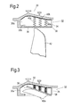
- FIG. 2 this shows generally at 30 a part of a fan case of a turbo fan engine.
- a fan track liner element 32 comprising a stiff body portion, or carcass, 34 and a movable wall portion 36 which is pivotably mounted on the carcass 34 by a hinge 38.
- the movable portion 36 is further connected to the carcass by biasing springs 40a, 40b and 40c.
- biasing springs 40a, 40b and 40c As an alternative to the springs a resilient foam or honeycomb could be used.
- the fan track liner element 32 is one of a plurality of such liner elements arranged circumferentially around the interior of the fan case 30.
- the fan case 30 is constructed in accordance with a previously known design using an Armco(RTM) style casing.
- the key difference between the present invention and previous case containment structures is in the fan track liners 32.
- the fan track liners are bonded in the fancase and designed for the blade to penetrate them in a fan blade off (FBO) event.
- the fan track liners are constructed with a movable portion 36 (or multiple portions) that are designed to be pushed outwards by the blade fragment rather than being penetrated.
- the fan track liner comprises several of the elements 32 each having an independently movable portion 36.
- each element 32 is frusto-conical in shape. If a cylindrical fan case is utilised the elements 32 would comprise sections of a cylinder.
- the moveable portion comprises an abradable layer and a rigid backing plate which is hingedly attached at one edge to the body and therefore allowed to pivot with respect to the body.
- the abradable surface is similar to those used in conventional fan track liners and is typically constructed of honeycomb material such as Nomex(RTM) which is optimised for ice resistance and blade tip sealing, and which can work effectively as a tip rub for the fan blades.
- the backing plate material can be metallic such as titanium alloy or stainless steel alloy for hardness.
- a composite material could be used as the backing plate. However, it must have sufficient hardness that a detached blade fragment will not damage it.
- the backing plate can be attached to a soft spring or further honeycomb filling (not shown) so that the blade fragment pushes the movable section of the liner without distorting the liner surface, but in any case the movable portion 36 must be stiffer than the springs 40 in order to resist radial deflection of the movable portion 36.
- the approach employed in the present invention utilises the fact that in an FBO event the fan blade fragment leading edge contacts the liner first, at a distance from the pivot. The energy from the fan blade fragment is sufficient to push the liner outwards and compress the springs 40 or honeycomb backing material behind the rigid backing plate.
- Figure 3 shows the movable portion 36 pivotally displaced by a fragment 42a of the fan blade.
- Deflection of the movable portion 36 absorbs a small amount of the blade energy.
- the rotating motion of the blade then causes it to move circumferentially around the fan case into a cavity in between the moveable portion of the adjacent FTL element and the fan case - i.e. into the space behind the movable portion of the circumferentially adjacent liner element 32.
- This space can be filed with shock-absorbing compressible material which absorbs more energy from the blade fragment.
- the motion can also be assisted by the impact of the trailing edge of the blade fragment.
- the blade fragment is retained in a recess 30a, known as the fan case "hook" and at the rear by a mounting ring (not shown) for the fan track liner.
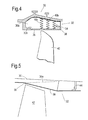
- FIG. 4 shows another embodiment of containment structure.
- the movable portion 36 has been chosen to be softer, and the springs 40 less resilient. This is to accommodate an ice shedding event. For ice shedding, the ice impact will take place much closer to the pivot. This means that to achieve the same moment as would be achieved by the displaced fan blade fragment the force required to deform or compress the honeycomb would be much greater due to the distance from the pivot being smaller.
- the honeycomb or spring can be made soft enough to resist the ice impact but still be able to deform upon contact by the blade fragment.
- the abradable liner system will absorb ice impacts without damage, as the energy from the ice will not be sufficiently great to deflect the movable portion 36.
- This gap 30b There is a small gap 30b between the edge of the movable portion 36 furthest from the hinge 38 and the wall of the casing 30.
- This gap may be filled or sealed using a sealing member (not shown) in order to avoid creating an aerodynamic disjoint. Filling of this gap also allows that the deflection of the movable portion 36 will not occur until sufficient force has been applied in order to break the seal. This approach can prevent the moveable member 36 from oscillating against the springs 40 during normal use, or inadvertently deploying under extreme manoeuvres or heavy landing, for example.
- FIG. 5 this shows in somewhat schematic form a further embodiment of containment structure.
- the hinge 38 is at a forward, or upstream, location.
- the broken line 36a depicts the movable portion 36 as it would be displaced in the event of an impact by a fan blade fragment.
- An annular, downstream or “backstop” retention element in the form of a containment wall 44 is provided to resist rearward motion of the blade fragment.
- the attachment of the movable portion 36 is opposite to that of the previous embodiment.
- the liner 32 is divided into segments, for example twelve circumferentially adjacent segments around the fan case, each of which has an independently movable portion 36.
- the mechanism of containment is the same as with the previous embodiment, namely that the leading edge of the fan blade fragment pushes upwards against the movable portion 36 to deflect it in order to create a slot into which the fan blade fragment may travel.
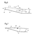
- FIG. 6 shows an alternative embodiment of containment structure with similar elements being labelled with like reference numerals as in previous embodiments. Description of these elements is omitted here.
- an annular wall 46 is built into the fan case to aid deflection of the fan blade fragment rearwards in the direction shown by arrow A.
- Figure 7 shows a further variation. Again, like reference numerals are used for like elements with description of these elements being omitted here.
- the position of the hinge 38 is further downstream as compared with the embodiment of Figure 6 .
- a compressible spring 40 holds the moveable portion 36 in position during normal operation.
- the containment structures according to the present invention provide a number of advantages compared with previous approaches. Since the majority of previously considered fan blade containment methods involved penetrating a hard lining material, such previously considered systems are unsuitable when fan blades other than conventional metallic fan blades with conventional shapes are used. With the present invention there is no need to physically penetrate a liner. Rather, the liner is effectively displaced temporarily by a blade fragment in order to create a space for the fragment to move into and thereafter be contained. Accordingly, the approach used in the present invention is suitable for use with any type of fan blade.
- the geometry employed by the present invention is more reliable at containing blade fragments since there is no risk that the fan blade fragment will fail to be engaged by the hook in the fan case, as would be the case if the fragment were to fail to penetrate a hard lining material in a previously considered containment system.
- a soft honeycomb material which can permanently deform to allow a fan blade fragment to be retained.
- This material could be a Nomex(RTM)-based phenolic honeycomb or an aluminium honeycomb.
- a foam material could also be utilised.
- the springs 40 can be of composite material or of metal.
- An additional feature could be that the gap 30b between the movable portion 38 and the fan case 30 could be filled with a honeycomb oriented at 90° to that of the rest of the honeycomb material.
- the strength of the honeycomb would be aligned with the motion of the blade and this could provide a degree of spring in a radial direction, to absorb the energy of ice impacts which allowing the profile of the fan track liner to be unaffected. However it would still provide a large amount of resistance to the fan blade fragment once it had pushed the liner outwards and moved into the void between the movable portion 36 and the fan case 30.
- the springs 40 could equally be replaced by bellows which could form acoustic cavities.
- the cavities could also act as part of the containment system for a blade fragment entering the case through an adjoining or adjacent moveable portion.
Abstract
the liner element comprising a body portion (34) mounted in a recess in the casing and a wall portion arranged to form part of an inner wall of the duct,
the wall portion and the body portion being attached and defining a containment cavity (30a) therebetween for containment of a detached fan blade fragment in use,
wherein the wall portion comprises a moveable portion (36) which is movable between a first configuration in which it lies substantially flush with the inner wall of the duct, and a second configuration in which it provides an opening through which a fan blade fragment can enter the containment cavity.
Description
- The present invention relates to a containment casing for an aero engine.
- In a ducted fan, such as is commonly used in an aero engine for example, a fan is disposed co-axially in a duct and is driven to rotate within the duct to direct air rearwardly through the duct.
- Turning to
Figure 1 , this shows schematically generally at 10, a previously considered turbofan aero engine comprising a core 12 which provides drive to arotary fan 14 having a plurality of circumferentially spacedfan blades 16 thereabout. Anacelle 18 surrounds the core 12 and is mounted thereon bystruts 20. The nacelle has aninlet 22 and anexhaust nozzle 24 and forms a duct casing around thefan 14. In use, air is drawn in via theinlet 22 and compressed by thefan 14. Some of the compressed air is fed into the core 12 which includes further compressor stages, a combustor and a turbine which drives the fan 14 (none of which are shown in this diagram). The rest of the air, so called bypass air, is directed around the core to the exhaust nozzle. Thrust is provided by both the exhaust from the core and the bypass air from the fan. - Although very rare, a fan-blade-off (FBO) event can occur, for example due to a foreign body, such as a bird, striking a fan blade and resulting in at least part of the fan blade becoming detached. Accordingly, the casing around the fan is typically provided with a containment structure designed to capture and retain the detached fragment of the fan blade, thereby preventing it from causing damage to any other part of the aircraft.
- The containment structure may for example consist of a plain or ribbed metallic casing, or a plain or isogrid Kevlar(RTM)-wrapped casing. The weight of the fan case assembly can account for between 5 and 10% of the engine weight due at least partially to the presence of such containment structures.
- In order to absorb that the high energies experienced in an FBO event, the casing materials are selected for high strength and high ductility. This requires the casing to be carefully designed using materials such as aluminium with Kevlar wrapping, ribbed Armco(RTM) or ribbed titanium alloy, to withstand the high forces generated when a fan blade is released.
- Early containment systems incorporated a steel band wrapped around the casing in the plane of the rotating fan blade. However, to reduce weight, a Kevlar-wrapped aluminium fan case was introduced. During an FBO event, the Kevlar can absorb the blade energy by deflecting and stretching and thus diverting the load around the casing. Any accessories bolted onto the outside of the fan case must be positioned outside of the so-called "Kevlar keep out zone", to ensure that there is no contact with the Kevlar "wave" and therefore that the accessories remain attached to the fan case following the failure of a fan blade.
- For efficiency and stability of the fan blades the gaps between the tips of the blades and the inner surface of the fan case must be kept to a minimum so as to minimise leakage of air around the tips of the blade.
- However, with smaller clearances between the blade tips and the duct casing comes the likelihood that some rubbing between the two will take place in certain operating conditions. For example, when the speed of rotation of the fan increases the blades can elongate due to centrifugal forces. Also during certain manoeuvres of the aircraft gyroscopic effects may temporarily cause the fan and the duct to come out of perfect axial alignment, which can lead to rubbing of the blade tips against the interior of the fan case.
- To accommodate this rubbing, the case is provided with a lining comprising a sacrificial abradable layer which is designed to be cut or rubbed away by the blade tips. The liner is sometimes referred to as a fan track liner (FTL).
- The majority of current methods of fan blade containment rely upon penetration of the fan track liner by the detached blade fragment. This mechanism is suitable for stiff, high energy debris with high pressure energies - i.e. it is suited to FBO events where the fan blade is of a conventional, widely used design and material. However, if the fan blade design is different from the conventional one, for example if the fan blade is made of a composite material or else has a wider tip than is conventional, then the previous approach to containment may be unsuitable and could potentially allow the blade to be uncontained. One reason that this may happen is that an increased area of the blade tip, for example, may significantly reduce the pressure energy available for the blade to penetrate the fan track liner.
- Also, with the ever present design imperative to reduce weight in the engine, lighter fan blades are being adopted which have less mass. Therefore less energy is available to penetrate the fan track liner in an FBO event. Again this could cause the blade to skid over the liner and remain uncontained.
- Furthermore, due to the increasing use of swept blades there are correspondingly increasing requirements to accommodate the shedding of ice. The impact area for any ice which is shed by a swept fan blade could be in the same location as the area where a blade fragment would impact during an FBO event. The pressure energies are similar in magnitude which may mean that a design which allows the blade to penetrate the FTL may not pass the ice shedding/impact regulation requirements, and conversely a liner which is designed to withstand ice impact may not allow the blade to penetrate the FTL and then be contained.
- In the case of the latter the fan case would fail a containment test and in the case of the former a significant additional after-market burden would be added both in terms of time and cost.
- An additional problem with previously considered designs is that in systems using Kevlar, the performance of the Kevlar degrades over time as it absorbs water, so any system using a Kevlar wrap as the containment structure gradually becomes less effective.
- Accordingly, the present invention aims to provide a containment structure for an aero engine, in which at least some of the aforementioned problems are addressed.
- The present invention is defined in the attached independent claims to which reference should now be made. Further preferred features may be found in the sub claims appended thereto.
- According to the invention there is provided a containment assembly for a turbo fan engine, comprising a casing arranged in use around a rotatable fan to form a duct for the fan, the containment assembly comprising at least one liner element disposed on an interior surface between the casing and blades of a rotatable fan, the liner element comprising a body portion mounted in a recess in the casing and a wall portion arranged to form part of an inner wall of the duct, the wall portion and the body portion being attached and defining a containment cavity therebetween for containment of a detached fan blade fragment in use, wherein the wall portion comprises a moveable portion which is movable between a first configuration in which it lies substantially flush with the inner wall of the duct, and a second configuration in which it provides an opening through which a fan blade fragment can enter the containment cavity.
- The movable portion is preferably mounted pivotally on the body portion.
- Preferably the movable portion is mounted hingedly on the body portion.
- In a preferred arrangement the movable portion is mounted resiliently on the body portion of the liner element.
- Preferably at least one spring is arranged to bias the movable portion in the first configuration.
- The containment cavity may contain shock absorbing-means.
- The liner element may comprise at least one deflector portion arranged in use to deflect a fan blade fragment rearwardly.
- Preferably the liner element comprises at least one containment feature arranged to limit rearward movement of a fan blade fragment.
- The wall portion preferably comprises an abradable material.
- The wall portion may comprise a honeycomb material.
- The casing and/or the moveable portion may comprise a sealing member arranged to provide a seal for a gap therebetween.
- The sealing member may be arranged to break the seal once a threshold force on the moveable member is exceeded.
- The invention also includes an aero engine according to any statement herein.
- Preferred embodiments of the present invention will now be described by way of example only, with reference to the accompanying diagrammatic drawings in which:
-
Figure 1 is a schematic view of a turbo fan engine; -
Figure 2 is a schematic sectional view of a fan case containment structure according to a first embodiment of the invention; -
Figure 3 is a further schematic view of the structure ofFigure 2 in an alternative configuration; -
Figure 4 shows schematically a second embodiment of fan case structure according to the invention; -
Figure 5 shows schematically a third embodiment of fan case containment structure according to the invention; -
Figure 6 shows schematically a fourth embodiment of fan case containment structure according to the invention; and -
Figure 7 shows schematically a fifth embodiment of fan case containment structure according to the present invention. - Turning to
Figure 2 , this shows generally at 30 a part of a fan case of a turbo fan engine. On the interior surface of thefan case 30 is mounted a fantrack liner element 32 comprising a stiff body portion, or carcass, 34 and amovable wall portion 36 which is pivotably mounted on thecarcass 34 by ahinge 38. - The
movable portion 36 is further connected to the carcass by biasingsprings track liner element 32 is one of a plurality of such liner elements arranged circumferentially around the interior of thefan case 30. - Rotating below the fan track liner in use are the blades of the fan, one of which shown at 42.
- The
fan case 30 is constructed in accordance with a previously known design using an Armco(RTM) style casing. The key difference between the present invention and previous case containment structures is in thefan track liners 32. With previously considered designs the fan track liners are bonded in the fancase and designed for the blade to penetrate them in a fan blade off (FBO) event. In accordance with the present invention the fan track liners are constructed with a movable portion 36 (or multiple portions) that are designed to be pushed outwards by the blade fragment rather than being penetrated. - The fan track liner comprises several of the
elements 32 each having an independentlymovable portion 36. With a convergent or divergent fan case, for aerodynamic purposes, eachelement 32 is frusto-conical in shape. If a cylindrical fan case is utilised theelements 32 would comprise sections of a cylinder. - The moveable portion comprises an abradable layer and a rigid backing plate which is hingedly attached at one edge to the body and therefore allowed to pivot with respect to the body. The abradable surface is similar to those used in conventional fan track liners and is typically constructed of honeycomb material such as Nomex(RTM) which is optimised for ice resistance and blade tip sealing, and which can work effectively as a tip rub for the fan blades.
- The backing plate material can be metallic such as titanium alloy or stainless steel alloy for hardness. A composite material could be used as the backing plate. However, it must have sufficient hardness that a detached blade fragment will not damage it.
- The backing plate can be attached to a soft spring or further honeycomb filling (not shown) so that the blade fragment pushes the movable section of the liner without distorting the liner surface, but in any case the
movable portion 36 must be stiffer than thesprings 40 in order to resist radial deflection of themovable portion 36. - The approach employed in the present invention utilises the fact that in an FBO event the fan blade fragment leading edge contacts the liner first, at a distance from the pivot. The energy from the fan blade fragment is sufficient to push the liner outwards and compress the
springs 40 or honeycomb backing material behind the rigid backing plate. -
Figure 3 shows themovable portion 36 pivotally displaced by afragment 42a of the fan blade. - Deflection of the
movable portion 36 absorbs a small amount of the blade energy. As the blade fragment pushes the movable portion upwards it slides up the surface into a gap created by the movement of the movable portion. The rotating motion of the blade then causes it to move circumferentially around the fan case into a cavity in between the moveable portion of the adjacent FTL element and the fan case - i.e. into the space behind the movable portion of the circumferentiallyadjacent liner element 32. This space can be filed with shock-absorbing compressible material which absorbs more energy from the blade fragment. The motion can also be assisted by the impact of the trailing edge of the blade fragment. At the front the blade fragment is retained in arecess 30a, known as the fan case "hook" and at the rear by a mounting ring (not shown) for the fan track liner. -
Figure 4 shows another embodiment of containment structure. In this embodiment themovable portion 36 has been chosen to be softer, and thesprings 40 less resilient. This is to accommodate an ice shedding event. For ice shedding, the ice impact will take place much closer to the pivot. This means that to achieve the same moment as would be achieved by the displaced fan blade fragment the force required to deform or compress the honeycomb would be much greater due to the distance from the pivot being smaller. Using this principle, the honeycomb or spring can be made soft enough to resist the ice impact but still be able to deform upon contact by the blade fragment. Thus the abradable liner system will absorb ice impacts without damage, as the energy from the ice will not be sufficiently great to deflect themovable portion 36. - There is a
small gap 30b between the edge of themovable portion 36 furthest from thehinge 38 and the wall of thecasing 30. This gap may be filled or sealed using a sealing member (not shown) in order to avoid creating an aerodynamic disjoint. Filling of this gap also allows that the deflection of themovable portion 36 will not occur until sufficient force has been applied in order to break the seal. This approach can prevent themoveable member 36 from oscillating against thesprings 40 during normal use, or inadvertently deploying under extreme manoeuvres or heavy landing, for example. - Turning to
Figure 5 , this shows in somewhat schematic form a further embodiment of containment structure. In this case thehinge 38 is at a forward, or upstream, location. Thebroken line 36a depicts themovable portion 36 as it would be displaced in the event of an impact by a fan blade fragment. An annular, downstream or "backstop" retention element in the form of acontainment wall 44 is provided to resist rearward motion of the blade fragment. In this example the attachment of themovable portion 36 is opposite to that of the previous embodiment. Again theliner 32 is divided into segments, for example twelve circumferentially adjacent segments around the fan case, each of which has an independentlymovable portion 36. The mechanism of containment is the same as with the previous embodiment, namely that the leading edge of the fan blade fragment pushes upwards against themovable portion 36 to deflect it in order to create a slot into which the fan blade fragment may travel. -
Figure 6 shows an alternative embodiment of containment structure with similar elements being labelled with like reference numerals as in previous embodiments. Description of these elements is omitted here. In this embodiment, anannular wall 46 is built into the fan case to aid deflection of the fan blade fragment rearwards in the direction shown by arrow A. -
Figure 7 shows a further variation. Again, like reference numerals are used for like elements with description of these elements being omitted here. InFigure 7 the position of thehinge 38 is further downstream as compared with the embodiment ofFigure 6 . Acompressible spring 40 holds themoveable portion 36 in position during normal operation. - The containment structures according to the present invention provide a number of advantages compared with previous approaches. Since the majority of previously considered fan blade containment methods involved penetrating a hard lining material, such previously considered systems are unsuitable when fan blades other than conventional metallic fan blades with conventional shapes are used. With the present invention there is no need to physically penetrate a liner. Rather, the liner is effectively displaced temporarily by a blade fragment in order to create a space for the fragment to move into and thereafter be contained. Accordingly, the approach used in the present invention is suitable for use with any type of fan blade.
- Furthermore, the performance of the system is not prone to degradation over time, as is the case with previously considered Kevlar systems.
- Finally, the geometry employed by the present invention is more reliable at containing blade fragments since there is no risk that the fan blade fragment will fail to be engaged by the hook in the fan case, as would be the case if the fragment were to fail to penetrate a hard lining material in a previously considered containment system.
- In the space between the
movable element 36 and thecarcass 34 can be a soft honeycomb material which can permanently deform to allow a fan blade fragment to be retained. This material could be a Nomex(RTM)-based phenolic honeycomb or an aluminium honeycomb. A foam material could also be utilised. Thesprings 40 can be of composite material or of metal. An additional feature could be that thegap 30b between themovable portion 38 and thefan case 30 could be filled with a honeycomb oriented at 90° to that of the rest of the honeycomb material. In this case the strength of the honeycomb would be aligned with the motion of the blade and this could provide a degree of spring in a radial direction, to absorb the energy of ice impacts which allowing the profile of the fan track liner to be unaffected. However it would still provide a large amount of resistance to the fan blade fragment once it had pushed the liner outwards and moved into the void between themovable portion 36 and thefan case 30. - The
springs 40 could equally be replaced by bellows which could form acoustic cavities. The cavities could also act as part of the containment system for a blade fragment entering the case through an adjoining or adjacent moveable portion.
Claims (13)
- A containment assembly for a turbo fan engine, comprising a casing (30) arranged in use around a rotatable fan, to form a duct for the fan, the containment assembly comprising at least one liner element (32) disposed on an interior surface between the casing and blades (42) of a rotatable fan,
the liner element comprising a body portion (34) mounted in a recess in the casing and a wall portion arranged to form part of an inner wall of the duct,
the wall portion and the body portion being attached and defining a containment cavity (30a) therebetween for containment of a detached fan blade fragment in use,
wherein the wall portion comprises a moveable portion (36) which is movable between a first configuration in which it lies substantially flush with the inner wall of the duct, and a second configuration in which it provides an opening through which a fan blade fragment can enter the containment cavity. - A containment assembly according to claim 1 wherein the movable portion is mounted pivotally on the body portion.
- A containment assembly according to claim 1 or claim 2 wherein the movable portion is mounted hingedly on the body portion.
- A containment assembly according to any of claims 1-3 wherein the movable portion is mounted resiliently on the body portion of the liner element.
- A containment assembly according to claim 4 wherein at least one spring (40a, 40b, 40c) is arranged to bias the movable portion (36) to the first configuration.
- A containment assembly according to any of claims 1-5 wherein the containment cavity contains shock absorbing means.
- A containment assembly according to any of claims 1-6 wherein the liner element comprises at least one deflector portion (46) arranged in use to deflect a fan blade fragment rearwardly.
- A containment assembly according to any of claims 1-7 wherein the liner element comprises at least one containment feature (44) arranged to limit rearward movement of a fan blade fragment.
- A containment assembly according to any of claims 1-8 wherein the wall portion comprises an abradable material.
- A containment assembly according to claim 9 wherein the wall portion comprises a honeycomb material.
- A containment assembly according to any of claims 1-10 wherein the casing and/or the moveable portion comprises a sealing member arranged to provide a seal for a gap therebetween.
- A containment assembly according to claim 11 wherein the sealing member is arranged to break the seal once a threshold force on the moveable member is exceeded.
- An aero engine comprising a containment assembly according to any of claims 1-10.
Applications Claiming Priority (1)
| Application Number | Priority Date | Filing Date | Title |
|---|---|---|---|
| GBGB0916823.8A GB0916823D0 (en) | 2009-09-25 | 2009-09-25 | Containment casing for an aero engine |
Publications (3)
| Publication Number | Publication Date |
|---|---|
| EP2305985A2 true EP2305985A2 (en) | 2011-04-06 |
| EP2305985A3 EP2305985A3 (en) | 2014-03-12 |
| EP2305985B1 EP2305985B1 (en) | 2017-06-28 |
Family
ID=41327565
Family Applications (1)
| Application Number | Title | Priority Date | Filing Date |
|---|---|---|---|
| EP10173514.0A Active EP2305985B1 (en) | 2009-09-25 | 2010-08-20 | Containment casing for an aero engine |
Country Status (3)
| Country | Link |
|---|---|
| US (1) | US8591172B2 (en) |
| EP (1) | EP2305985B1 (en) |
| GB (1) | GB0916823D0 (en) |
Cited By (16)
| Publication number | Priority date | Publication date | Assignee | Title |
|---|---|---|---|---|
| GB2488628A (en) * | 2011-03-04 | 2012-09-05 | Rolls Royce Plc | Turbomachine casing with energy absorbing element |
| EP2600008A1 (en) * | 2011-11-30 | 2013-06-05 | Rolls-Royce plc | Turbomachine casing assembly with blade containment cavity |
| EP2620652A1 (en) * | 2012-01-25 | 2013-07-31 | Rolls-Royce plc | A turbomachine casing assembly with blade containment cavity |
| EP2620654A1 (en) * | 2012-01-25 | 2013-07-31 | Rolls-Royce plc | A turbomachine casing assembly with blade containment cavity |
| EP2767676A1 (en) * | 2013-02-13 | 2014-08-20 | Rolls-Royce plc | Fan containment system, corresponding fan assembly and gas turbine engine |
| WO2014137411A1 (en) * | 2013-03-04 | 2014-09-12 | Rolls-Royce Corporation | Fan track liner assembly with a spring element |
| EP2796668A3 (en) * | 2013-04-24 | 2015-01-21 | MTU Aero Engines GmbH | Casing section of a turbo engine compressor or turbo engine turbine stage |
| EP2829687A1 (en) * | 2013-07-23 | 2015-01-28 | MTU Aero Engines GmbH | Housing containment and method of production |
| EP2876289A1 (en) * | 2013-11-21 | 2015-05-27 | Rolls-Royce plc | Fan containment system for a gas turbine engine |
| EP2940283A1 (en) * | 2014-03-26 | 2015-11-04 | Rolls-Royce plc | Turbomachine fan casing assembly |
| FR3044053A1 (en) * | 2015-11-25 | 2017-05-26 | Snecma | NACELLE FOR A TURBOJET ENGINE |
| EP2597270A3 (en) * | 2011-11-22 | 2018-03-21 | Rolls-Royce plc | A Turbomachine Casing Assembly |
| US10174633B2 (en) | 2015-10-30 | 2019-01-08 | Rolls-Royce Corporation | Containment hook for composite fan case |
| CN109677624A (en) * | 2017-10-19 | 2019-04-26 | 波音公司 | Sealing system for the variable-geometry gap in aircraft system |
| GB2539217B (en) * | 2015-06-09 | 2020-02-12 | Rolls Royce Plc | Fan casing assembly |
| WO2022208801A1 (en) * | 2021-03-31 | 2022-10-06 | 川崎重工業株式会社 | Fan case assembly for turbofan engine |
Families Citing this family (16)
| Publication number | Priority date | Publication date | Assignee | Title |
|---|---|---|---|---|
| GB2459646B (en) * | 2008-04-28 | 2011-03-30 | Rolls Royce Plc | A fan assembly |
| US9109462B2 (en) * | 2011-12-15 | 2015-08-18 | United Technologies Corporation | Energy-absorbing fan case for a gas turbine engine |
| EP3049643A4 (en) * | 2013-09-25 | 2016-10-12 | United Technologies Corp | Combined fan case ice liner and rear liner |
| GB201401767D0 (en) | 2014-02-03 | 2014-03-19 | Rolls Royce Plc | Gas turbine engine |
| GB201408688D0 (en) * | 2014-05-16 | 2014-07-02 | Rolls Royce Plc | Gas turbine engine |
| US10260522B2 (en) * | 2016-05-19 | 2019-04-16 | Rolls-Royce Corporation | Liner system |
| US10550718B2 (en) | 2017-03-31 | 2020-02-04 | The Boeing Company | Gas turbine engine fan blade containment systems |
| US10487684B2 (en) | 2017-03-31 | 2019-11-26 | The Boeing Company | Gas turbine engine fan blade containment systems |
| US10677261B2 (en) * | 2017-04-13 | 2020-06-09 | General Electric Company | Turbine engine and containment assembly for use in a turbine engine |
| US10538856B2 (en) | 2017-05-02 | 2020-01-21 | General Electric Company | Apparatus and method for electro-polishing complex shapes |
| US11215069B2 (en) | 2017-05-16 | 2022-01-04 | General Electric Company | Softwall containment systems |
| US10480530B2 (en) * | 2017-08-25 | 2019-11-19 | United Technologies Corporation | Fan Containment case for gas turbine engines |
| BE1026058B1 (en) * | 2018-03-01 | 2019-10-01 | Safran Aero Boosters S.A. | GASKET FOR AXIAL TURBOMACHINE COMPRESSOR |
| GB201811549D0 (en) | 2018-07-13 | 2018-08-29 | Rolls Royce Plc | Fan blade containment |
| JP6990639B2 (en) * | 2018-09-26 | 2022-01-12 | 本田技研工業株式会社 | Turbofan engine |
| US11300049B2 (en) * | 2020-03-09 | 2022-04-12 | Rolls-Royce North American Technologies Inc. | Inlet guide vane draw heat exchanger system |
Family Cites Families (39)
| Publication number | Priority date | Publication date | Assignee | Title |
|---|---|---|---|---|
| US3948346A (en) * | 1974-04-02 | 1976-04-06 | Mcdonnell Douglas Corporation | Multi-layered acoustic liner |
| US4149824A (en) * | 1976-12-23 | 1979-04-17 | General Electric Company | Blade containment device |
| US4934899A (en) * | 1981-12-21 | 1990-06-19 | United Technologies Corporation | Method for containing particles in a rotary machine |
| US5188505A (en) * | 1991-10-07 | 1993-02-23 | General Electric Company | Structural ring mechanism for containment housing of turbofan |
| US5205708A (en) * | 1992-02-07 | 1993-04-27 | General Electric Company | High pressure turbine component interference fit up |
| US5267828A (en) * | 1992-11-13 | 1993-12-07 | General Electric Company | Removable fan shroud panel |
| GB9307288D0 (en) | 1993-04-07 | 1993-06-02 | Rolls Royce Plc | Gas turbine engine casing construction |
| US5528904A (en) * | 1994-02-28 | 1996-06-25 | Jones; Charles R. | Coated hot gas duct liner |
| GB2288639B (en) * | 1994-04-20 | 1998-10-21 | Rolls Royce Plc | Ducted fan gas turbine engine nacelle assembly |
| US5482429A (en) * | 1994-04-29 | 1996-01-09 | United Technologies Corporation | Fan blade containment assembly |
| US5431532A (en) * | 1994-05-20 | 1995-07-11 | General Electric Company | Blade containment system |
| US6637186B1 (en) * | 1997-11-11 | 2003-10-28 | United Technologies Corporation | Fan case liner |
| US6182531B1 (en) * | 1998-06-12 | 2001-02-06 | The Boeing Company | Containment ring for flywheel failure |
| GB9812992D0 (en) * | 1998-06-17 | 1998-08-12 | Rolls Royce Plc | A gas turbine engine containment casing |
| FR2780443B1 (en) * | 1998-06-25 | 2000-08-04 | Snecma | HIGH PRESSURE TURBINE STATOR RING OF A TURBOMACHINE |
| US6149380A (en) * | 1999-02-04 | 2000-11-21 | Pratt & Whitney Canada Corp. | Hardwall fan case with structured bumper |
| US6206631B1 (en) * | 1999-09-07 | 2001-03-27 | General Electric Company | Turbomachine fan casing with dual-wall blade containment structure |
| GB9921935D0 (en) * | 1999-09-17 | 1999-11-17 | Rolls Royce | A nacelle assembly for a gas turbine engine |
| US6227794B1 (en) * | 1999-12-16 | 2001-05-08 | Pratt & Whitney Canada Corp. | Fan case with flexible conical ring |
| WO2001066914A1 (en) * | 2000-03-07 | 2001-09-13 | Mitsubishi Heavy Industries, Ltd. | Gas turbine split ring |
| GB2365926B (en) | 2000-08-12 | 2004-12-08 | Rolls Royce Plc | A gas turbine engine blade containment assembly |
| GB0116988D0 (en) * | 2000-08-11 | 2001-09-05 | Rolls Royce Plc | A gas turbine engine blade containment assembly |
| US6619913B2 (en) * | 2002-02-15 | 2003-09-16 | General Electric Company | Fan casing acoustic treatment |
| GB0206136D0 (en) * | 2002-03-15 | 2002-04-24 | Rolls Royce Plc | Improvements in or relating to cellular materials |
| US6695574B1 (en) * | 2002-08-21 | 2004-02-24 | Pratt & Whitney Canada Corp. | Energy absorber and deflection device |
| GB2418957B (en) | 2003-10-22 | 2006-07-05 | Rolls Royce Plc | A liner for a gas turbine engine casing |
| GB0403941D0 (en) | 2004-02-21 | 2004-03-24 | Rolls Royce Plc | A gas turbine engine blade containment assembly |
| FR2867224B1 (en) * | 2004-03-04 | 2006-05-19 | Snecma Moteurs | AXIAL AXIS HOLDING DEVICE FOR RING OF A TURBOMACHINE HIGH-PRESSURE TURBINE |
| FR2868814B1 (en) * | 2004-04-09 | 2009-12-18 | Snecma Moteurs | DEVICE FOR ASSEMBLING ANNULAR FLANGES, PARTICULARLY IN A TURBOMACHINE |
| GB0408825D0 (en) | 2004-04-20 | 2004-05-26 | Rolls Royce Plc | A rotor blade containment assembly for a gas turbine engine |
| GB2416192B (en) | 2004-07-14 | 2006-09-27 | Rolls Royce Plc | Ducted fan with containment structure |
| GB0501284D0 (en) | 2005-01-21 | 2005-03-02 | Rolls Royce Plc | Aerofoil containment structure |
| GB2426287B (en) * | 2005-05-18 | 2007-05-30 | Rolls Royce Plc | Blade containment structure |
| GB0704879D0 (en) * | 2007-03-14 | 2007-04-18 | Rolls Royce Plc | A Casing arrangement |
| GB0707099D0 (en) * | 2007-04-13 | 2007-05-23 | Rolls Royce Plc | A casing |
| GB0803479D0 (en) * | 2008-02-27 | 2008-04-02 | Rolls Royce Plc | Fan track liner assembly |
| GB2459844B (en) | 2008-05-06 | 2011-01-19 | Rolls Royce Plc | Fan section |
| GB0813821D0 (en) * | 2008-07-29 | 2008-09-03 | Rolls Royce Plc | A fan casing for a gas turbine engine |
| US8202041B2 (en) * | 2008-10-31 | 2012-06-19 | Pratt & Whitney Canada Corp | Fan case for turbofan engine |
-
2009
- 2009-09-25 GB GBGB0916823.8A patent/GB0916823D0/en not_active Ceased
-
2010
- 2010-08-20 EP EP10173514.0A patent/EP2305985B1/en active Active
- 2010-09-01 US US12/873,650 patent/US8591172B2/en active Active
Non-Patent Citations (1)
| Title |
|---|
| None |
Cited By (22)
| Publication number | Priority date | Publication date | Assignee | Title |
|---|---|---|---|---|
| US9222368B2 (en) | 2011-03-04 | 2015-12-29 | Rolls-Royce Plc | Turbomachine casing assembly |
| US9206706B2 (en) | 2011-03-04 | 2015-12-08 | Rolls-Royce Plc | Turbomachine casing assembly |
| GB2488628A (en) * | 2011-03-04 | 2012-09-05 | Rolls Royce Plc | Turbomachine casing with energy absorbing element |
| EP2597270A3 (en) * | 2011-11-22 | 2018-03-21 | Rolls-Royce plc | A Turbomachine Casing Assembly |
| EP2600008A1 (en) * | 2011-11-30 | 2013-06-05 | Rolls-Royce plc | Turbomachine casing assembly with blade containment cavity |
| US9085992B2 (en) | 2011-11-30 | 2015-07-21 | Rolls-Royce Plc | Turbomachine casing assembly |
| EP2620654A1 (en) * | 2012-01-25 | 2013-07-31 | Rolls-Royce plc | A turbomachine casing assembly with blade containment cavity |
| EP2620652A1 (en) * | 2012-01-25 | 2013-07-31 | Rolls-Royce plc | A turbomachine casing assembly with blade containment cavity |
| EP2767676A1 (en) * | 2013-02-13 | 2014-08-20 | Rolls-Royce plc | Fan containment system, corresponding fan assembly and gas turbine engine |
| US9598978B2 (en) | 2013-02-13 | 2017-03-21 | Rolls-Royce Plc | Fan containment system |
| WO2014137411A1 (en) * | 2013-03-04 | 2014-09-12 | Rolls-Royce Corporation | Fan track liner assembly with a spring element |
| EP2796668A3 (en) * | 2013-04-24 | 2015-01-21 | MTU Aero Engines GmbH | Casing section of a turbo engine compressor or turbo engine turbine stage |
| EP2829687A1 (en) * | 2013-07-23 | 2015-01-28 | MTU Aero Engines GmbH | Housing containment and method of production |
| US9683490B2 (en) | 2013-11-21 | 2017-06-20 | Rolls-Royce Plc | Pivoting fan track liner for blade retainment |
| EP2876289A1 (en) * | 2013-11-21 | 2015-05-27 | Rolls-Royce plc | Fan containment system for a gas turbine engine |
| EP2940283A1 (en) * | 2014-03-26 | 2015-11-04 | Rolls-Royce plc | Turbomachine fan casing assembly |
| US9810096B2 (en) | 2014-03-26 | 2017-11-07 | Rolls-Royce Plc | Turbomachine fan casing assembly |
| GB2539217B (en) * | 2015-06-09 | 2020-02-12 | Rolls Royce Plc | Fan casing assembly |
| US10174633B2 (en) | 2015-10-30 | 2019-01-08 | Rolls-Royce Corporation | Containment hook for composite fan case |
| FR3044053A1 (en) * | 2015-11-25 | 2017-05-26 | Snecma | NACELLE FOR A TURBOJET ENGINE |
| CN109677624A (en) * | 2017-10-19 | 2019-04-26 | 波音公司 | Sealing system for the variable-geometry gap in aircraft system |
| WO2022208801A1 (en) * | 2021-03-31 | 2022-10-06 | 川崎重工業株式会社 | Fan case assembly for turbofan engine |
Also Published As
| Publication number | Publication date |
|---|---|
| US20110076132A1 (en) | 2011-03-31 |
| EP2305985A3 (en) | 2014-03-12 |
| GB0916823D0 (en) | 2009-11-04 |
| US8591172B2 (en) | 2013-11-26 |
| EP2305985B1 (en) | 2017-06-28 |
Similar Documents
| Publication | Publication Date | Title |
|---|---|---|
| EP2305985B1 (en) | Containment casing for an aero engine | |
| EP2767676B1 (en) | Fan containment system, corresponding fan assembly and gas turbine engine | |
| EP2600008B1 (en) | Turbomachine casing assembly with blade containment cavity | |
| EP2149680B1 (en) | Gas turbine engine | |
| EP2149679B1 (en) | Fan casing for a gas turbine engine | |
| EP2290199B1 (en) | A turbomachine casing assembly | |
| US11035245B2 (en) | Fan track liner | |
| US9683490B2 (en) | Pivoting fan track liner for blade retainment | |
| EP2290196A2 (en) | Adjustable fan case liner and mounting method | |
| US9677570B2 (en) | Gas turbine engine | |
| JP2001241397A (en) | Fan case for turbo fan engine having fan decoupler | |
| EP2902593B1 (en) | Fan containment system in an axial gas turbine engine | |
| US9835046B2 (en) | Gas turbine engine | |
| CA2883295A1 (en) | Rub tolerant fan case | |
| EP3002421B1 (en) | Fan track liner assembly | |
| US20210054762A1 (en) | Gas turbine engine fan bumper | |
| GB2523069A (en) | Gas turbine engine |
Legal Events
| Date | Code | Title | Description |
|---|---|---|---|
| PUAI | Public reference made under article 153(3) epc to a published international application that has entered the european phase |
Free format text: ORIGINAL CODE: 0009012 |
|
| AK | Designated contracting states |
Kind code of ref document: A2 Designated state(s): AL AT BE BG CH CY CZ DE DK EE ES FI FR GB GR HR HU IE IS IT LI LT LU LV MC MK MT NL NO PL PT RO SE SI SK SM TR |
|
| AX | Request for extension of the european patent |
Extension state: BA ME RS |
|
| PUAL | Search report despatched |
Free format text: ORIGINAL CODE: 0009013 |
|
| AK | Designated contracting states |
Kind code of ref document: A3 Designated state(s): AL AT BE BG CH CY CZ DE DK EE ES FI FR GB GR HR HU IE IS IT LI LT LU LV MC MK MT NL NO PL PT RO SE SI SK SM TR |
|
| AX | Request for extension of the european patent |
Extension state: BA ME RS |
|
| RIC1 | Information provided on ipc code assigned before grant |
Ipc: F02C 7/05 20060101AFI20140206BHEP Ipc: F01D 21/04 20060101ALI20140206BHEP Ipc: F01D 25/26 20060101ALI20140206BHEP Ipc: B64D 33/02 20060101ALI20140206BHEP |
|
| 17P | Request for examination filed |
Effective date: 20140912 |
|
| RBV | Designated contracting states (corrected) |
Designated state(s): AL AT BE BG CH CY CZ DE DK EE ES FI FR GB GR HR HU IE IS IT LI LT LU LV MC MK MT NL NO PL PT RO SE SI SK SM TR |
|
| RAP1 | Party data changed (applicant data changed or rights of an application transferred) |
Owner name: ROLLS-ROYCE PLC |
|
| GRAP | Despatch of communication of intention to grant a patent |
Free format text: ORIGINAL CODE: EPIDOSNIGR1 |
|
| INTG | Intention to grant announced |
Effective date: 20170420 |
|
| GRAS | Grant fee paid |
Free format text: ORIGINAL CODE: EPIDOSNIGR3 |
|
| GRAA | (expected) grant |
Free format text: ORIGINAL CODE: 0009210 |
|
| AK | Designated contracting states |
Kind code of ref document: B1 Designated state(s): AL AT BE BG CH CY CZ DE DK EE ES FI FR GB GR HR HU IE IS IT LI LT LU LV MC MK MT NL NO PL PT RO SE SI SK SM TR |
|
| REG | Reference to a national code |
Ref country code: GB Ref legal event code: FG4D |
|
| REG | Reference to a national code |
Ref country code: CH Ref legal event code: EP |
|
| REG | Reference to a national code |
Ref country code: AT Ref legal event code: REF Ref document number: 905062 Country of ref document: AT Kind code of ref document: T Effective date: 20170715 |
|
| REG | Reference to a national code |
Ref country code: IE Ref legal event code: FG4D |
|
| REG | Reference to a national code |
Ref country code: DE Ref legal event code: R096 Ref document number: 602010043238 Country of ref document: DE |
|
| REG | Reference to a national code |
Ref country code: FR Ref legal event code: PLFP Year of fee payment: 8 |
|
| PG25 | Lapsed in a contracting state [announced via postgrant information from national office to epo] |
Ref country code: HR Free format text: LAPSE BECAUSE OF FAILURE TO SUBMIT A TRANSLATION OF THE DESCRIPTION OR TO PAY THE FEE WITHIN THE PRESCRIBED TIME-LIMIT Effective date: 20170628 Ref country code: NO Free format text: LAPSE BECAUSE OF FAILURE TO SUBMIT A TRANSLATION OF THE DESCRIPTION OR TO PAY THE FEE WITHIN THE PRESCRIBED TIME-LIMIT Effective date: 20170928 Ref country code: LT Free format text: LAPSE BECAUSE OF FAILURE TO SUBMIT A TRANSLATION OF THE DESCRIPTION OR TO PAY THE FEE WITHIN THE PRESCRIBED TIME-LIMIT Effective date: 20170628 Ref country code: GR Free format text: LAPSE BECAUSE OF FAILURE TO SUBMIT A TRANSLATION OF THE DESCRIPTION OR TO PAY THE FEE WITHIN THE PRESCRIBED TIME-LIMIT Effective date: 20170929 Ref country code: FI Free format text: LAPSE BECAUSE OF FAILURE TO SUBMIT A TRANSLATION OF THE DESCRIPTION OR TO PAY THE FEE WITHIN THE PRESCRIBED TIME-LIMIT Effective date: 20170628 |
|
| REG | Reference to a national code |
Ref country code: NL Ref legal event code: MP Effective date: 20170628 |
|
| REG | Reference to a national code |
Ref country code: LT Ref legal event code: MG4D |
|
| REG | Reference to a national code |
Ref country code: AT Ref legal event code: MK05 Ref document number: 905062 Country of ref document: AT Kind code of ref document: T Effective date: 20170628 |
|
| PG25 | Lapsed in a contracting state [announced via postgrant information from national office to epo] |
Ref country code: BG Free format text: LAPSE BECAUSE OF FAILURE TO SUBMIT A TRANSLATION OF THE DESCRIPTION OR TO PAY THE FEE WITHIN THE PRESCRIBED TIME-LIMIT Effective date: 20170928 Ref country code: SE Free format text: LAPSE BECAUSE OF FAILURE TO SUBMIT A TRANSLATION OF THE DESCRIPTION OR TO PAY THE FEE WITHIN THE PRESCRIBED TIME-LIMIT Effective date: 20170628 Ref country code: LV Free format text: LAPSE BECAUSE OF FAILURE TO SUBMIT A TRANSLATION OF THE DESCRIPTION OR TO PAY THE FEE WITHIN THE PRESCRIBED TIME-LIMIT Effective date: 20170628 Ref country code: NL Free format text: LAPSE BECAUSE OF FAILURE TO SUBMIT A TRANSLATION OF THE DESCRIPTION OR TO PAY THE FEE WITHIN THE PRESCRIBED TIME-LIMIT Effective date: 20170628 |
|
| PG25 | Lapsed in a contracting state [announced via postgrant information from national office to epo] |
Ref country code: SK Free format text: LAPSE BECAUSE OF FAILURE TO SUBMIT A TRANSLATION OF THE DESCRIPTION OR TO PAY THE FEE WITHIN THE PRESCRIBED TIME-LIMIT Effective date: 20170628 Ref country code: RO Free format text: LAPSE BECAUSE OF FAILURE TO SUBMIT A TRANSLATION OF THE DESCRIPTION OR TO PAY THE FEE WITHIN THE PRESCRIBED TIME-LIMIT Effective date: 20170628 Ref country code: EE Free format text: LAPSE BECAUSE OF FAILURE TO SUBMIT A TRANSLATION OF THE DESCRIPTION OR TO PAY THE FEE WITHIN THE PRESCRIBED TIME-LIMIT Effective date: 20170628 Ref country code: CZ Free format text: LAPSE BECAUSE OF FAILURE TO SUBMIT A TRANSLATION OF THE DESCRIPTION OR TO PAY THE FEE WITHIN THE PRESCRIBED TIME-LIMIT Effective date: 20170628 Ref country code: AT Free format text: LAPSE BECAUSE OF FAILURE TO SUBMIT A TRANSLATION OF THE DESCRIPTION OR TO PAY THE FEE WITHIN THE PRESCRIBED TIME-LIMIT Effective date: 20170628 |
|
| PG25 | Lapsed in a contracting state [announced via postgrant information from national office to epo] |
Ref country code: SM Free format text: LAPSE BECAUSE OF FAILURE TO SUBMIT A TRANSLATION OF THE DESCRIPTION OR TO PAY THE FEE WITHIN THE PRESCRIBED TIME-LIMIT Effective date: 20170628 Ref country code: ES Free format text: LAPSE BECAUSE OF FAILURE TO SUBMIT A TRANSLATION OF THE DESCRIPTION OR TO PAY THE FEE WITHIN THE PRESCRIBED TIME-LIMIT Effective date: 20170628 Ref country code: IS Free format text: LAPSE BECAUSE OF FAILURE TO SUBMIT A TRANSLATION OF THE DESCRIPTION OR TO PAY THE FEE WITHIN THE PRESCRIBED TIME-LIMIT Effective date: 20171028 Ref country code: PL Free format text: LAPSE BECAUSE OF FAILURE TO SUBMIT A TRANSLATION OF THE DESCRIPTION OR TO PAY THE FEE WITHIN THE PRESCRIBED TIME-LIMIT Effective date: 20170628 Ref country code: IT Free format text: LAPSE BECAUSE OF FAILURE TO SUBMIT A TRANSLATION OF THE DESCRIPTION OR TO PAY THE FEE WITHIN THE PRESCRIBED TIME-LIMIT Effective date: 20170628 |
|
| REG | Reference to a national code |
Ref country code: CH Ref legal event code: PL Ref country code: DE Ref legal event code: R097 Ref document number: 602010043238 Country of ref document: DE |
|
| PG25 | Lapsed in a contracting state [announced via postgrant information from national office to epo] |
Ref country code: MC Free format text: LAPSE BECAUSE OF FAILURE TO SUBMIT A TRANSLATION OF THE DESCRIPTION OR TO PAY THE FEE WITHIN THE PRESCRIBED TIME-LIMIT Effective date: 20170628 |
|
| PG25 | Lapsed in a contracting state [announced via postgrant information from national office to epo] |
Ref country code: DK Free format text: LAPSE BECAUSE OF FAILURE TO SUBMIT A TRANSLATION OF THE DESCRIPTION OR TO PAY THE FEE WITHIN THE PRESCRIBED TIME-LIMIT Effective date: 20170628 Ref country code: LI Free format text: LAPSE BECAUSE OF NON-PAYMENT OF DUE FEES Effective date: 20170831 Ref country code: CH Free format text: LAPSE BECAUSE OF NON-PAYMENT OF DUE FEES Effective date: 20170831 |
|
| PLBE | No opposition filed within time limit |
Free format text: ORIGINAL CODE: 0009261 |
|
| STAA | Information on the status of an ep patent application or granted ep patent |
Free format text: STATUS: NO OPPOSITION FILED WITHIN TIME LIMIT |
|
| REG | Reference to a national code |
Ref country code: IE Ref legal event code: MM4A |
|
| REG | Reference to a national code |
Ref country code: BE Ref legal event code: MM Effective date: 20170831 |
|
| 26N | No opposition filed |
Effective date: 20180329 |
|
| PG25 | Lapsed in a contracting state [announced via postgrant information from national office to epo] |
Ref country code: LU Free format text: LAPSE BECAUSE OF NON-PAYMENT OF DUE FEES Effective date: 20170820 |
|
| PG25 | Lapsed in a contracting state [announced via postgrant information from national office to epo] |
Ref country code: IE Free format text: LAPSE BECAUSE OF NON-PAYMENT OF DUE FEES Effective date: 20170820 |
|
| REG | Reference to a national code |
Ref country code: FR Ref legal event code: PLFP Year of fee payment: 9 |
|
| PG25 | Lapsed in a contracting state [announced via postgrant information from national office to epo] |
Ref country code: SI Free format text: LAPSE BECAUSE OF FAILURE TO SUBMIT A TRANSLATION OF THE DESCRIPTION OR TO PAY THE FEE WITHIN THE PRESCRIBED TIME-LIMIT Effective date: 20170628 Ref country code: BE Free format text: LAPSE BECAUSE OF NON-PAYMENT OF DUE FEES Effective date: 20170831 |
|
| PG25 | Lapsed in a contracting state [announced via postgrant information from national office to epo] |
Ref country code: MT Free format text: LAPSE BECAUSE OF NON-PAYMENT OF DUE FEES Effective date: 20170820 |
|
| PG25 | Lapsed in a contracting state [announced via postgrant information from national office to epo] |
Ref country code: HU Free format text: LAPSE BECAUSE OF FAILURE TO SUBMIT A TRANSLATION OF THE DESCRIPTION OR TO PAY THE FEE WITHIN THE PRESCRIBED TIME-LIMIT; INVALID AB INITIO Effective date: 20100820 |
|
| PG25 | Lapsed in a contracting state [announced via postgrant information from national office to epo] |
Ref country code: CY Free format text: LAPSE BECAUSE OF NON-PAYMENT OF DUE FEES Effective date: 20170628 |
|
| PG25 | Lapsed in a contracting state [announced via postgrant information from national office to epo] |
Ref country code: MK Free format text: LAPSE BECAUSE OF FAILURE TO SUBMIT A TRANSLATION OF THE DESCRIPTION OR TO PAY THE FEE WITHIN THE PRESCRIBED TIME-LIMIT Effective date: 20170628 |
|
| PG25 | Lapsed in a contracting state [announced via postgrant information from national office to epo] |
Ref country code: TR Free format text: LAPSE BECAUSE OF FAILURE TO SUBMIT A TRANSLATION OF THE DESCRIPTION OR TO PAY THE FEE WITHIN THE PRESCRIBED TIME-LIMIT Effective date: 20170628 |
|
| PG25 | Lapsed in a contracting state [announced via postgrant information from national office to epo] |
Ref country code: PT Free format text: LAPSE BECAUSE OF FAILURE TO SUBMIT A TRANSLATION OF THE DESCRIPTION OR TO PAY THE FEE WITHIN THE PRESCRIBED TIME-LIMIT Effective date: 20170628 |
|
| PG25 | Lapsed in a contracting state [announced via postgrant information from national office to epo] |
Ref country code: AL Free format text: LAPSE BECAUSE OF FAILURE TO SUBMIT A TRANSLATION OF THE DESCRIPTION OR TO PAY THE FEE WITHIN THE PRESCRIBED TIME-LIMIT Effective date: 20170628 |
|
| PGFP | Annual fee paid to national office [announced via postgrant information from national office to epo] |
Ref country code: DE Payment date: 20220826 Year of fee payment: 13 |
|
| P01 | Opt-out of the competence of the unified patent court (upc) registered |
Effective date: 20230528 |
|
| PGFP | Annual fee paid to national office [announced via postgrant information from national office to epo] |
Ref country code: GB Payment date: 20230822 Year of fee payment: 14 |
|
| PGFP | Annual fee paid to national office [announced via postgrant information from national office to epo] |
Ref country code: FR Payment date: 20230824 Year of fee payment: 14 |
|
| REG | Reference to a national code |
Ref country code: DE Ref legal event code: R119 Ref document number: 602010043238 Country of ref document: DE |