EP2309044A2 - Method and apparatus for manufacturing vehicle parts - Google Patents
Method and apparatus for manufacturing vehicle parts Download PDFInfo
- Publication number
- EP2309044A2 EP2309044A2 EP20100185375 EP10185375A EP2309044A2 EP 2309044 A2 EP2309044 A2 EP 2309044A2 EP 20100185375 EP20100185375 EP 20100185375 EP 10185375 A EP10185375 A EP 10185375A EP 2309044 A2 EP2309044 A2 EP 2309044A2
- Authority
- EP
- European Patent Office
- Prior art keywords
- mold cavity
- plastic
- mold
- volume
- covering
- Prior art date
- Legal status (The legal status is an assumption and is not a legal conclusion. Google has not performed a legal analysis and makes no representation as to the accuracy of the status listed.)
- Withdrawn
Links
Images


Classifications
-
- B—PERFORMING OPERATIONS; TRANSPORTING
- B29—WORKING OF PLASTICS; WORKING OF SUBSTANCES IN A PLASTIC STATE IN GENERAL
- B29C—SHAPING OR JOINING OF PLASTICS; SHAPING OF MATERIAL IN A PLASTIC STATE, NOT OTHERWISE PROVIDED FOR; AFTER-TREATMENT OF THE SHAPED PRODUCTS, e.g. REPAIRING
- B29C45/00—Injection moulding, i.e. forcing the required volume of moulding material through a nozzle into a closed mould; Apparatus therefor
- B29C45/14—Injection moulding, i.e. forcing the required volume of moulding material through a nozzle into a closed mould; Apparatus therefor incorporating preformed parts or layers, e.g. injection moulding around inserts or for coating articles
- B29C45/14778—Injection moulding, i.e. forcing the required volume of moulding material through a nozzle into a closed mould; Apparatus therefor incorporating preformed parts or layers, e.g. injection moulding around inserts or for coating articles the article consisting of a material with particular properties, e.g. porous, brittle
-
- B—PERFORMING OPERATIONS; TRANSPORTING
- B29—WORKING OF PLASTICS; WORKING OF SUBSTANCES IN A PLASTIC STATE IN GENERAL
- B29C—SHAPING OR JOINING OF PLASTICS; SHAPING OF MATERIAL IN A PLASTIC STATE, NOT OTHERWISE PROVIDED FOR; AFTER-TREATMENT OF THE SHAPED PRODUCTS, e.g. REPAIRING
- B29C45/00—Injection moulding, i.e. forcing the required volume of moulding material through a nozzle into a closed mould; Apparatus therefor
- B29C45/16—Making multilayered or multicoloured articles
-
- B—PERFORMING OPERATIONS; TRANSPORTING
- B29—WORKING OF PLASTICS; WORKING OF SUBSTANCES IN A PLASTIC STATE IN GENERAL
- B29C—SHAPING OR JOINING OF PLASTICS; SHAPING OF MATERIAL IN A PLASTIC STATE, NOT OTHERWISE PROVIDED FOR; AFTER-TREATMENT OF THE SHAPED PRODUCTS, e.g. REPAIRING
- B29C45/00—Injection moulding, i.e. forcing the required volume of moulding material through a nozzle into a closed mould; Apparatus therefor
- B29C45/17—Component parts, details or accessories; Auxiliary operations
- B29C45/46—Means for plasticising or homogenising the moulding material or forcing it into the mould
- B29C45/56—Means for plasticising or homogenising the moulding material or forcing it into the mould using mould parts movable during or after injection, e.g. injection-compression moulding
- B29C45/561—Injection-compression moulding
-
- D—TEXTILES; PAPER
- D04—BRAIDING; LACE-MAKING; KNITTING; TRIMMINGS; NON-WOVEN FABRICS
- D04H—MAKING TEXTILE FABRICS, e.g. FROM FIBRES OR FILAMENTARY MATERIAL; FABRICS MADE BY SUCH PROCESSES OR APPARATUS, e.g. FELTS, NON-WOVEN FABRICS; COTTON-WOOL; WADDING ; NON-WOVEN FABRICS FROM STAPLE FIBRES, FILAMENTS OR YARNS, BONDED WITH AT LEAST ONE WEB-LIKE MATERIAL DURING THEIR CONSOLIDATION
- D04H1/00—Non-woven fabrics formed wholly or mainly of staple fibres or like relatively short fibres
-
- B—PERFORMING OPERATIONS; TRANSPORTING
- B29—WORKING OF PLASTICS; WORKING OF SUBSTANCES IN A PLASTIC STATE IN GENERAL
- B29C—SHAPING OR JOINING OF PLASTICS; SHAPING OF MATERIAL IN A PLASTIC STATE, NOT OTHERWISE PROVIDED FOR; AFTER-TREATMENT OF THE SHAPED PRODUCTS, e.g. REPAIRING
- B29C45/00—Injection moulding, i.e. forcing the required volume of moulding material through a nozzle into a closed mould; Apparatus therefor
- B29C2045/0098—Injection moulding, i.e. forcing the required volume of moulding material through a nozzle into a closed mould; Apparatus therefor shearing of the moulding material, e.g. for obtaining molecular orientation or reducing the viscosity
-
- B—PERFORMING OPERATIONS; TRANSPORTING
- B29—WORKING OF PLASTICS; WORKING OF SUBSTANCES IN A PLASTIC STATE IN GENERAL
- B29C—SHAPING OR JOINING OF PLASTICS; SHAPING OF MATERIAL IN A PLASTIC STATE, NOT OTHERWISE PROVIDED FOR; AFTER-TREATMENT OF THE SHAPED PRODUCTS, e.g. REPAIRING
- B29C45/00—Injection moulding, i.e. forcing the required volume of moulding material through a nozzle into a closed mould; Apparatus therefor
- B29C45/17—Component parts, details or accessories; Auxiliary operations
- B29C45/46—Means for plasticising or homogenising the moulding material or forcing it into the mould
- B29C45/56—Means for plasticising or homogenising the moulding material or forcing it into the mould using mould parts movable during or after injection, e.g. injection-compression moulding
- B29C45/561—Injection-compression moulding
- B29C2045/563—Enlarging the mould cavity during injection
-
- B—PERFORMING OPERATIONS; TRANSPORTING
- B29—WORKING OF PLASTICS; WORKING OF SUBSTANCES IN A PLASTIC STATE IN GENERAL
- B29C—SHAPING OR JOINING OF PLASTICS; SHAPING OF MATERIAL IN A PLASTIC STATE, NOT OTHERWISE PROVIDED FOR; AFTER-TREATMENT OF THE SHAPED PRODUCTS, e.g. REPAIRING
- B29C45/00—Injection moulding, i.e. forcing the required volume of moulding material through a nozzle into a closed mould; Apparatus therefor
- B29C45/17—Component parts, details or accessories; Auxiliary operations
- B29C45/46—Means for plasticising or homogenising the moulding material or forcing it into the mould
- B29C45/56—Means for plasticising or homogenising the moulding material or forcing it into the mould using mould parts movable during or after injection, e.g. injection-compression moulding
- B29C45/561—Injection-compression moulding
- B29C2045/564—Compression drive means acting independently from the mould closing and clamping means
-
- B—PERFORMING OPERATIONS; TRANSPORTING
- B29—WORKING OF PLASTICS; WORKING OF SUBSTANCES IN A PLASTIC STATE IN GENERAL
- B29C—SHAPING OR JOINING OF PLASTICS; SHAPING OF MATERIAL IN A PLASTIC STATE, NOT OTHERWISE PROVIDED FOR; AFTER-TREATMENT OF THE SHAPED PRODUCTS, e.g. REPAIRING
- B29C45/00—Injection moulding, i.e. forcing the required volume of moulding material through a nozzle into a closed mould; Apparatus therefor
- B29C45/14—Injection moulding, i.e. forcing the required volume of moulding material through a nozzle into a closed mould; Apparatus therefor incorporating preformed parts or layers, e.g. injection moulding around inserts or for coating articles
- B29C45/14311—Injection moulding, i.e. forcing the required volume of moulding material through a nozzle into a closed mould; Apparatus therefor incorporating preformed parts or layers, e.g. injection moulding around inserts or for coating articles using means for bonding the coating to the articles
-
- B—PERFORMING OPERATIONS; TRANSPORTING
- B29—WORKING OF PLASTICS; WORKING OF SUBSTANCES IN A PLASTIC STATE IN GENERAL
- B29C—SHAPING OR JOINING OF PLASTICS; SHAPING OF MATERIAL IN A PLASTIC STATE, NOT OTHERWISE PROVIDED FOR; AFTER-TREATMENT OF THE SHAPED PRODUCTS, e.g. REPAIRING
- B29C45/00—Injection moulding, i.e. forcing the required volume of moulding material through a nozzle into a closed mould; Apparatus therefor
- B29C45/16—Making multilayered or multicoloured articles
- B29C45/1635—Making multilayered or multicoloured articles using displaceable mould parts, e.g. retractable partition between adjacent mould cavities
-
- B—PERFORMING OPERATIONS; TRANSPORTING
- B29—WORKING OF PLASTICS; WORKING OF SUBSTANCES IN A PLASTIC STATE IN GENERAL
- B29K—INDEXING SCHEME ASSOCIATED WITH SUBCLASSES B29B, B29C OR B29D, RELATING TO MOULDING MATERIALS OR TO MATERIALS FOR MOULDS, REINFORCEMENTS, FILLERS OR PREFORMED PARTS, e.g. INSERTS
- B29K2713/00—Use of textile products or fabrics for preformed parts, e.g. for inserts
-
- B—PERFORMING OPERATIONS; TRANSPORTING
- B29—WORKING OF PLASTICS; WORKING OF SUBSTANCES IN A PLASTIC STATE IN GENERAL
- B29L—INDEXING SCHEME ASSOCIATED WITH SUBCLASS B29C, RELATING TO PARTICULAR ARTICLES
- B29L2031/00—Other particular articles
- B29L2031/30—Vehicles, e.g. ships or aircraft, or body parts thereof
- B29L2031/3005—Body finishings
- B29L2031/3041—Trim panels
-
- Y—GENERAL TAGGING OF NEW TECHNOLOGICAL DEVELOPMENTS; GENERAL TAGGING OF CROSS-SECTIONAL TECHNOLOGIES SPANNING OVER SEVERAL SECTIONS OF THE IPC; TECHNICAL SUBJECTS COVERED BY FORMER USPC CROSS-REFERENCE ART COLLECTIONS [XRACs] AND DIGESTS
- Y10—TECHNICAL SUBJECTS COVERED BY FORMER USPC
- Y10T—TECHNICAL SUBJECTS COVERED BY FORMER US CLASSIFICATION
- Y10T428/00—Stock material or miscellaneous articles
- Y10T428/249921—Web or sheet containing structurally defined element or component
-
- Y—GENERAL TAGGING OF NEW TECHNOLOGICAL DEVELOPMENTS; GENERAL TAGGING OF CROSS-SECTIONAL TECHNOLOGIES SPANNING OVER SEVERAL SECTIONS OF THE IPC; TECHNICAL SUBJECTS COVERED BY FORMER USPC CROSS-REFERENCE ART COLLECTIONS [XRACs] AND DIGESTS
- Y10—TECHNICAL SUBJECTS COVERED BY FORMER USPC
- Y10T—TECHNICAL SUBJECTS COVERED BY FORMER US CLASSIFICATION
- Y10T428/00—Stock material or miscellaneous articles
- Y10T428/31504—Composite [nonstructural laminate]
-
- Y—GENERAL TAGGING OF NEW TECHNOLOGICAL DEVELOPMENTS; GENERAL TAGGING OF CROSS-SECTIONAL TECHNOLOGIES SPANNING OVER SEVERAL SECTIONS OF THE IPC; TECHNICAL SUBJECTS COVERED BY FORMER USPC CROSS-REFERENCE ART COLLECTIONS [XRACs] AND DIGESTS
- Y10—TECHNICAL SUBJECTS COVERED BY FORMER USPC
- Y10T—TECHNICAL SUBJECTS COVERED BY FORMER US CLASSIFICATION
- Y10T442/00—Fabric [woven, knitted, or nonwoven textile or cloth, etc.]
- Y10T442/20—Coated or impregnated woven, knit, or nonwoven fabric which is not [a] associated with another preformed layer or fiber layer or, [b] with respect to woven and knit, characterized, respectively, by a particular or differential weave or knit, wherein the coating or impregnation is neither a foamed material nor a free metal or alloy layer
-
- Y—GENERAL TAGGING OF NEW TECHNOLOGICAL DEVELOPMENTS; GENERAL TAGGING OF CROSS-SECTIONAL TECHNOLOGIES SPANNING OVER SEVERAL SECTIONS OF THE IPC; TECHNICAL SUBJECTS COVERED BY FORMER USPC CROSS-REFERENCE ART COLLECTIONS [XRACs] AND DIGESTS
- Y10—TECHNICAL SUBJECTS COVERED BY FORMER USPC
- Y10T—TECHNICAL SUBJECTS COVERED BY FORMER US CLASSIFICATION
- Y10T442/00—Fabric [woven, knitted, or nonwoven textile or cloth, etc.]
- Y10T442/30—Woven fabric [i.e., woven strand or strip material]
- Y10T442/3049—Including strand precoated with other than free metal or alloy
-
- Y—GENERAL TAGGING OF NEW TECHNOLOGICAL DEVELOPMENTS; GENERAL TAGGING OF CROSS-SECTIONAL TECHNOLOGIES SPANNING OVER SEVERAL SECTIONS OF THE IPC; TECHNICAL SUBJECTS COVERED BY FORMER USPC CROSS-REFERENCE ART COLLECTIONS [XRACs] AND DIGESTS
- Y10—TECHNICAL SUBJECTS COVERED BY FORMER USPC
- Y10T—TECHNICAL SUBJECTS COVERED BY FORMER US CLASSIFICATION
- Y10T442/00—Fabric [woven, knitted, or nonwoven textile or cloth, etc.]
- Y10T442/30—Woven fabric [i.e., woven strand or strip material]
- Y10T442/3854—Woven fabric with a preformed polymeric film or sheet
Definitions
- the invention relates to a method for manufacturing vehicle parts from plastic in a mold.
- Plastic vehicle parts are typically manufactured by injection molding. Because these parts are typically relatively large in proportion to their wall thickness, this requires large, heavy-duty injection molding machines, being costly in purchase and use. Enlarging the wall thicknesses, which renders flowing easier, entails a prolonged injection molding cycle, increased material use, increased weight and can lead to unwanted stresses. This is therefore an undesirable solution.
- the object of the invention is to provide a method for manufacturing vehicle elements, whereby at least a number of the drawbacks known from the prior art are prevented. To that end, a method according to the invention is characterized by the features according to claim 1.
- the plastic can be introduced into the mold cavity at relatively low temperature, after which the plastic, through movement of at least one wall part of the mold cavity, is brought into its eventually desired shape. That requires relatively little force and hence relatively little pressure.
- the mold cavity is reduced so fast as to result in adiabatic heat development in the plastic, so that the flow behavior of the plastic is further improved.
- the plastic In reducing the volume of the mold cavity, the plastic is forced in the direction of the ends of the mold cavity, whereby at all times the optimum ratio between the melt flow index and the incidental flow path can be obtained.
- the mold can be kept closed with a particularly low closing force compared with closing forces required in conventional injection molding technique for manufacturing a comparable product.
- An additional advantage of a method according to the invention is that it allows wall thicknesses to be reduced locally, even to a thickness below that which can be achieved with conventional injection molding technique in a product of comparable dimensions, without unwanted stress concentrations occurring.
- inserts can be laid in the mold cavity, for fastening in or to the plastic. Since low pressures and flow rates are achieved, these inserts will not be damaged, at least less easily than in conventional technique.
- labels in particular in-mold labels, can be placed for obtaining a desired finish.
- decorative labels can be used for coloring or patterns, such as, for instance, wood finish.
- natural materials can be used, for instance wood.
- inserts can be used that are based on textile, such as woven or nonwoven textile. With such inserts, covering panels can be manufactured in one piece, in one production pass, while moreover a switch in material for the covering can be made particularly fast and simply.
- an inner covering panel for a door, seat, wall finish, roof lining or the like can be manufactured, with one side covered with a fabric covering matching the interior of the vehicle.
- Fabric or textile is here understood to mean at least comprising natural or synthetic woven or nonwoven materials. It is then preferred that the textile, at least the fabric, is provided with a plastic backing and/or plastic threads or threads which are covered with plastic, for instance as warp and/or weft, so that a proper connection can be obtained with the plastic from which the part is manufactured.
- plate parts can be manufactured for, for instance, the outside of a vehicle, such as bodywork parts for a car or boat or covering panels for airplanes and ships.
- a desired profiling or other surface finish can be directly obtained, for instance drop or rib structures for influencing air resistance, flow, dirt repulsion and the like.
- a part is built up by injection molding different layers against each other, as described in claim 8.
- the volume of the mold cavity is enlarged each time after an injection molding pass, after which a new layer of plastic is introduced into the thus created space.
- a gleaming inner layer for a reflector can be injection molded, after which a support is formed from a suitable plastic against the "outer side" thereof, or vice versa.
- sandwich constructions can be manufactured.
- manufacturing costs can be considerably reduced and accuracy enhanced, while mechanical properties can be considerably improved.
- the volume of the mold cavity is enlarged and subsequently reduced to the shape of the desired product.
- the movable wall part can also be pushed away by the injected plastic, so that a constant back pressure is maintained and a suitable flow path melt flow index ratio is maintained at all times.
- Such a method is particularly suitable for, for instance, PET.
- a method and mold according to the invention can be used particularly suitably for a variety of covering elements such as TRIM parts and the like, plating, bodywork parts and the like.
- the speed of moving the or each movable wall part is preferably chosen to be higher than the speed at which the mold is opened and/or closed.
- the closing pressure can be kept relatively low, for instance lower than the injection pressure for the plastic, at least lower than such an injection pressure for conventional injection molding of a comparable product.
- the invention furthermore relates to a vehicle part according to claim 15 and to a textile for use according to claim 19, as well as to a mold according to claim 20.
- a mold 50 comprising a first part 51 and a second part 52, while in the second part 52 a movable wall part 53 is provided, operable from outside of the mold 50 by arms 54, schematically represented in Figs. 1 and 2 .
- a mold cavity 55 is recessed, a portion of which is defined by the movable wall part 53.
- a vehicle part 1 such as a covering element, can be formed.
- the movable wall part 53 is moved in the direction of the first part 51 to a second position, so that the volume of the mold cavity decreases to the desired end volume, while or whereupon holding pressure is applied in the usual manner to fill the mold cavity completely and obtain a substantially stress-free product.
- a vehicle part 1 has been formed being wholly dimensionally stable.
- the mold 50 is kept closed, represented schematically by closing elements 56.
- Fig. 3 schematically shows in sectional side view an alternative embodiment of a mold 50 according to the invention, again with two mold parts 51, 52 and a mold cavity 55.
- the mold cavity 55 in this embodiment is bounded on one side by a movable wall part 53, controllably movable with the aid of drive means 60, such as piston rods 61 movable by pistons 62.
- drive means 60 such as piston rods 61 movable by pistons 62.
- the movable wall part 53 can be moved to a first position, shown in Fig. 3A ; to a second position, in which the volume of the mold cavity 55 is reduced, as shown in Fig. 3B ; or to a third position, as shown in Fig. 3C , in which the volume is increased still further.
- a product as shown in Fig. 4 can be manufactured.
- a label 63 has been laid, for instance, on the wall part 53 or on the opposite part 51.
- a first layer of plastic 64 has been injected against the label.
- the movable wall part 53 has been retracted into the third position as shown in Fig. 3C , after which a second layer of plastic 65 has been injection molded against it.
- the label 63 and/or the first layer 64 can be, for instance, reflecting and resistant to, for instance, heating by lamps, while the second layer of plastic 65 can serve as carrier.
- Fig. 5 shows schematically in sectional side view a covering panel for, for instance, a door, seat, wall or like vehicle parts.
- This vehicle part comprises a plate-shaped carrier 2, which can be mounted in a vehicle, for instance in a door, with mounting lugs 3 which have been integrally injection molded or have been provided as inserts.
- a covering 4 is provided, substantially manufactured from textile in the embodiment shown.
- This can be a woven or nonwoven textile, preferably matching a vehicle interior.
- the textile may be manufactured from synthetic and from natural materials.
- This covering 4 has been arranged by placing it in a mold cavity 55, similarly to in-mold labeling technique, after which the panel 2 has been formed against it with a method as described earlier.
- a covering panel can be obtained in one piece in this way.
- Fig. 6 shows, enlarged, a portion of a panel 1 according to Fig. 5 , comprising the panel 2 and the covering 4.
- the covering 4 is provided with a carrier 5 manufactured from a plastic compatible with the plastic of the panel 2, such that these are connected through fusion and/or chemical bonding.
- a proper connection has been obtained.
- the textile of the covering 4 is protected by the layer 5.
- a woven textile can be used, with at least a portion of warp and/or weft being provided with a plastic covering or being designed in plastic, comparably compatible with the plastic of the panel 2. In that way too, a proper connection can be obtained.
- Fig. 7 shows schematically an alternative embodiment of a panel 1 according to the invention, again comprising a carrier 2 with a covering 4, which covering, in this embodiment, is arranged as a label, for instance for decorative purposes.
- the label 4 can have a profiling, for instance ribs, drops or the like, so that flow can be influenced, resistance can be changed, the appearance can be modified, and so forth.
- vehicle parts can be manufactured for, for instance, cars, airplanes, and ships, in particular trim elements, such as inner coverings, dashboards, roof lining and door covering elements, or external covering elements, such as plating parts, bumpers, engine covering and guarding parts, parts of seats, seat benches, bodywork parts and the like. Also, in this way, for instance complete doors, hoods, boot lids and the like can be manufactured, as well as sliding roofs and the like.
- trim elements such as inner coverings, dashboards, roof lining and door covering elements
- external covering elements such as plating parts, bumpers, engine covering and guarding parts, parts of seats, seat benches, bodywork parts and the like.
- complete doors, hoods, boot lids and the like can be manufactured, as well as sliding roofs and the like.
- the movable wall part 53 is held in a forwardly moved second position during injection of plastic, so as to be pushed away by the plastic to the first position.
- This is specifically advantageous for, for instance, low melt plastics or plastics such as PET, specifically if these are to be translucent.
- movable wall parts can be combined in a mold cavity, which can be moved simultaneously or sequentially.
- the movable wall parts can move both rectilinearly and along curves, for instance for the controlled displacement of plastic.
- the plastic can be introduced in molten condition but may also be introduced as granulate or the like directly into the mold cavity.
- Parts manufactured with a method according to the invention can be provided on one or more sides with a finish or covering such as textile or label, for instance from plastic.
Abstract
- at least partly closing the mold, wherein the at least one mold cavity is brought in a first position by means of at least one movable wall part of the at least one mold cavity;
- introducing plastic into the at least one mold cavity;
- upon complete closure of the mold and/or movement of the at least one movable wall part, bringing the at least one mold cavity in a second position, the at least one mold cavity in the second position having a different volume than in the first position;
- all this in such a manner that by bringing the at least one mold cavity from the first into the second position, the plastic fills the respective mold cavity completely.
Description
- The invention relates to a method for manufacturing vehicle parts from plastic in a mold.
- Plastic vehicle parts are typically manufactured by injection molding. Because these parts are typically relatively large in proportion to their wall thickness, this requires large, heavy-duty injection molding machines, being costly in purchase and use. Enlarging the wall thicknesses, which renders flowing easier, entails a prolonged injection molding cycle, increased material use, increased weight and can lead to unwanted stresses. This is therefore an undesirable solution.
- It has previously been proposed to make use of cascade injection molding techniques, whereby a flow front moving through the mold is obtained. However, this requires special injection molding machines and peripheral equipment therefor and makes placement of inserts such as labels and the like, fastening elements and strengthening elements difficult to apply.
- The object of the invention is to provide a method for manufacturing vehicle elements, whereby at least a number of the drawbacks known from the prior art are prevented. To that end, a method according to the invention is characterized by the features according to
claim 1. - In a method according to the invention, it has surprisingly been found that, as a consequence, the plastic can be introduced into the mold cavity at relatively low temperature, after which the plastic, through movement of at least one wall part of the mold cavity, is brought into its eventually desired shape. That requires relatively little force and hence relatively little pressure. Without wishing to be bound to any theory, this seems to be at least the result of the fact that as the mold cavity can be temporarily enlarged, the plastic can flow into the mold cavity with less back pressure, while moreover the plastic needed for the part only needs to spread over a smaller surface. Preferably, further, the mold cavity is reduced so fast as to result in adiabatic heat development in the plastic, so that the flow behavior of the plastic is further improved. In reducing the volume of the mold cavity, the plastic is forced in the direction of the ends of the mold cavity, whereby at all times the optimum ratio between the melt flow index and the incidental flow path can be obtained. As a result, the mold can be kept closed with a particularly low closing force compared with closing forces required in conventional injection molding technique for manufacturing a comparable product.
- An additional advantage of a method according to the invention is that it allows wall thicknesses to be reduced locally, even to a thickness below that which can be achieved with conventional injection molding technique in a product of comparable dimensions, without unwanted stress concentrations occurring.
- With a method according to the invention, furthermore, inserts can be laid in the mold cavity, for fastening in or to the plastic. Since low pressures and flow rates are achieved, these inserts will not be damaged, at least less easily than in conventional technique. Thus, for instance, labels, in particular in-mold labels, can be placed for obtaining a desired finish. For instance, decorative labels can be used for coloring or patterns, such as, for instance, wood finish. Also, natural materials can be used, for instance wood. Further, inserts can be used that are based on textile, such as woven or nonwoven textile. With such inserts, covering panels can be manufactured in one piece, in one production pass, while moreover a switch in material for the covering can be made particularly fast and simply.
- Thus, for instance, an inner covering panel for a door, seat, wall finish, roof lining or the like can be manufactured, with one side covered with a fabric covering matching the interior of the vehicle. Fabric or textile is here understood to mean at least comprising natural or synthetic woven or nonwoven materials. It is then preferred that the textile, at least the fabric, is provided with a plastic backing and/or plastic threads or threads which are covered with plastic, for instance as warp and/or weft, so that a proper connection can be obtained with the plastic from which the part is manufactured.
- Also plate parts can be manufactured for, for instance, the outside of a vehicle, such as bodywork parts for a car or boat or covering panels for airplanes and ships. With the aid of labels or the like, a desired profiling or other surface finish can be directly obtained, for instance drop or rib structures for influencing air resistance, flow, dirt repulsion and the like.
- In an alternative embodiment, in a mold, a part is built up by injection molding different layers against each other, as described in claim 8.
- In such a method, the volume of the mold cavity is enlarged each time after an injection molding pass, after which a new layer of plastic is introduced into the thus created space. Thus, for instance, in a light unit, first a gleaming inner layer for a reflector can be injection molded, after which a support is formed from a suitable plastic against the "outer side" thereof, or vice versa. Also, in this way, sandwich constructions can be manufactured. Thus, manufacturing costs can be considerably reduced and accuracy enhanced, while mechanical properties can be considerably improved.
- Preferably, when injecting plastic via an injection point such as a hot runner, the volume of the mold cavity is enlarged and subsequently reduced to the shape of the desired product. Alternatively, the movable wall part can also be pushed away by the injected plastic, so that a constant back pressure is maintained and a suitable flow path melt flow index ratio is maintained at all times. Such a method is particularly suitable for, for instance, PET.
- A method and mold according to the invention can be used particularly suitably for a variety of covering elements such as TRIM parts and the like, plating, bodywork parts and the like.
- The speed of moving the or each movable wall part is preferably chosen to be higher than the speed at which the mold is opened and/or closed. The closing pressure can be kept relatively low, for instance lower than the injection pressure for the plastic, at least lower than such an injection pressure for conventional injection molding of a comparable product.
- The invention furthermore relates to a vehicle part according to claim 15 and to a textile for use according to claim 19, as well as to a mold according to claim 20.
- In the further claims, advantageous embodiments of the invention are shown and described.
- To clarify the invention, exemplary embodiments of a method and apparatus according to the invention, as well as of products thereby obtained are presently described with reference to the drawing, wherein:
-
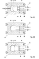
Fig. 1 shows schematically in sectional side view a mold for manufacturing a vehicle part according to the invention, in a first phase of manufacture; -
Fig. 2 shows the mold according toFig. 1 during a second phase of manufacture; -
Figs. 3A-C show an alternative embodiment of a mold according to the invention; -
Fig. 4 shows schematically in sectional side view a vehicle part manufactured with a mold according toFig. 3 ; -
Fig. 5 shows in sectional side view a covering panel according to the invention; -
Fig. 6 shows, enlarged, a portion of a panel according toFig. 5 ; and -
Fig. 7 shows in sectional side view a portion of an alternative embodiment of a covering panel according to the invention. - In this description, the same or corresponding parts have the same or corresponding reference numerals.
- The exemplary embodiments shown in the drawing are shown only by way of illustration and should not be construed as limiting in any way.
- In
Fig. 1 , amold 50 is shown, comprising afirst part 51 and asecond part 52, while in the second part 52 amovable wall part 53 is provided, operable from outside of themold 50 byarms 54, schematically represented inFigs. 1 and 2 . Within themold 50, amold cavity 55 is recessed, a portion of which is defined by themovable wall part 53. In themold cavity 55, avehicle part 1, such as a covering element, can be formed. When injection molding is started, plastic is introduced into themold cavity 55 withmovable wall part 53 retracted in a first position, that is, the space of themold cavity 55 is relatively large. Next, when themold cavity 55 is substantially completely filled with plastic, for instance upwards of 80%, themovable wall part 53 is moved in the direction of thefirst part 51 to a second position, so that the volume of the mold cavity decreases to the desired end volume, while or whereupon holding pressure is applied in the usual manner to fill the mold cavity completely and obtain a substantially stress-free product. In the position shown inFig. 2 , avehicle part 1 has been formed being wholly dimensionally stable. It is clear that during injection molding, themold 50 is kept closed, represented schematically byclosing elements 56. With such a method, in a particularly simple manner, apart 1 can be manufactured which is relatively dimensionally stable, using relatively light tools, and moreover a high degree of freedom in the choice of plastic is obtained. This is because by virtue of the movable wall part, during the major part of the filling of the mold, large flow paths are obtained, so that plastics having a high as well as plastics having a very low melt can be used. -
Fig. 3 schematically shows in sectional side view an alternative embodiment of amold 50 according to the invention, again with twomold parts mold cavity 55. Themold cavity 55 in this embodiment is bounded on one side by amovable wall part 53, controllably movable with the aid of drive means 60, such aspiston rods 61 movable bypistons 62. Of course, there may be different operating means, for instance screw means, electrically operable means, pneumatic means and the like. With these, themovable wall part 53 can be moved to a first position, shown inFig. 3A ; to a second position, in which the volume of themold cavity 55 is reduced, as shown inFig. 3B ; or to a third position, as shown inFig. 3C , in which the volume is increased still further. - With such a
mold 50, for instance a product as shown inFig. 4 can be manufactured. In this case, alabel 63 has been laid, for instance, on thewall part 53 or on theopposite part 51. Next, a first layer ofplastic 64 has been injected against the label. Next, themovable wall part 53 has been retracted into the third position as shown inFig. 3C , after which a second layer ofplastic 65 has been injection molded against it. Thus, a sandwich construction has been obtained. Thelabel 63 and/or thefirst layer 64 can be, for instance, reflecting and resistant to, for instance, heating by lamps, while the second layer ofplastic 65 can serve as carrier. - It will be clear that with a comparable mold, also multiple layers can be provided and that also differently shaped products can be manufactured, for instance sandwich panels and the like.
-
Fig. 5 shows schematically in sectional side view a covering panel for, for instance, a door, seat, wall or like vehicle parts. This vehicle part comprises a plate-shapedcarrier 2, which can be mounted in a vehicle, for instance in a door, with mountinglugs 3 which have been integrally injection molded or have been provided as inserts. On the opposite side, acovering 4 is provided, substantially manufactured from textile in the embodiment shown. This can be a woven or nonwoven textile, preferably matching a vehicle interior. The textile may be manufactured from synthetic and from natural materials. Thiscovering 4 has been arranged by placing it in amold cavity 55, similarly to in-mold labeling technique, after which thepanel 2 has been formed against it with a method as described earlier. As a result of the relatively low pressures that occur in the mold cavity and relatively low temperatures, at least on the side of the textile, a covering panel can be obtained in one piece in this way. -
Fig. 6 shows, enlarged, a portion of apanel 1 according toFig. 5 , comprising thepanel 2 and thecovering 4. It shows that thecovering 4 is provided with acarrier 5 manufactured from a plastic compatible with the plastic of thepanel 2, such that these are connected through fusion and/or chemical bonding. As a result, a proper connection has been obtained. Moreover, the textile of thecovering 4 is protected by thelayer 5. Alternatively, a woven textile can be used, with at least a portion of warp and/or weft being provided with a plastic covering or being designed in plastic, comparably compatible with the plastic of thepanel 2. In that way too, a proper connection can be obtained. -
Fig. 7 shows schematically an alternative embodiment of apanel 1 according to the invention, again comprising acarrier 2 with acovering 4, which covering, in this embodiment, is arranged as a label, for instance for decorative purposes. Thelabel 4 can have a profiling, for instance ribs, drops or the like, so that flow can be influenced, resistance can be changed, the appearance can be modified, and so forth. - With a method according to the present invention, vehicle parts can be manufactured for, for instance, cars, airplanes, and ships, in particular trim elements, such as inner coverings, dashboards, roof lining and door covering elements, or external covering elements, such as plating parts, bumpers, engine covering and guarding parts, parts of seats, seat benches, bodywork parts and the like. Also, in this way, for instance complete doors, hoods, boot lids and the like can be manufactured, as well as sliding roofs and the like.
- In an alternative embodiment, the
movable wall part 53 is held in a forwardly moved second position during injection of plastic, so as to be pushed away by the plastic to the first position. This is specifically advantageous for, for instance, low melt plastics or plastics such as PET, specifically if these are to be translucent. - The invention is not limited in any way to the embodiments as shown and described. Many variations thereon are possible within the framework of the invention outlined by the claims.
- Thus, also other parts can be manufactured with a method according to the invention, in particular according to claim 8. Also, multiple movable wall parts can be combined in a mold cavity, which can be moved simultaneously or sequentially. The movable wall parts can move both rectilinearly and along curves, for instance for the controlled displacement of plastic. The plastic can be introduced in molten condition but may also be introduced as granulate or the like directly into the mold cavity.
- Parts manufactured with a method according to the invention can be provided on one or more sides with a finish or covering such as textile or label, for instance from plastic.
Claims (21)
- A method for manufacturing at least partly plastic vehicle parts in a mold with at least one mold cavity, comprising the steps of:- at least partly closing the mold, wherein the at least one mold cavity is brought in a first position by means of at least one movable wall part of the at least one mold cavity;- introducing plastic into the at least one mold cavity;- upon complete closure of the mold and/or movement of said at least one movable wall part, bringing the at least one mold cavity in a second position, the at least one mold cavity in said second position having a different volume than in the first position;- all this in such a manner that by bringing the at least one mold cavity from the first in the second position, the plastic fills the respective mold cavity completely.
- A method according to claim 1, wherein at least one insert, in particular a covering element such as a label, is laid in or is formed in the at least one mold cavity, which insert is connected with the plastic in the mold.
- A method according to claim 2, wherein said covering element is at least partly manufactured from textile.
- A method according to claim 2 or 3, wherein said covering element is at least partly manufactured from plastic, in particular a thermoplastic plastic.
- A method according to claim 4, wherein said plastic in said covering element is compatible with the plastic which is introduced into the mold cavity.
- A method according to any one of the preceding claims, wherein the at least one mold cavity in the second position has a volume that is smaller than in the first position.
- A method according to any one of claims 1-5, wherein the at least one mold cavity in the first position has a smaller volume than in the second position, while preferably said wall part is moved by at least the plastic which is introduced into the respective mold cavity.
- A method for manufacturing products in a mold, in particular according to any one of the preceding claims, wherein after introduction of plastic into the at least one mold cavity, the mold, at least the at least one mold cavity, is enlarged in volume, after which a second plastic is introduced into the thus obtained space in the mold cavity.
- A method according to claim 8, wherein the at least one mold cavity in the first position has a first volume, in the second position a second volume and wherein the volume of said at least one mold cavity, after introduction of said plastic, is enlarged to a third volume, greater than the first and second volume, after which the volume of said at least one mold cavity, after introduction of the second plastic, is reduced to approximately said second volume.
- A method according to any one of the preceding claims, wherein vehicle parts are manufactured selected from the group of covering elements, in particular TRIM elements such as inner covering, dashboards, roof lining and door covering elements, or external covering elements, such as plating parts, bumpers, engine covering and guarding parts, parts of seats and seat benches and the like.
- A method according to any one of the preceding claims, wherein a mold is used provided with at least one mold cavity with at least one movable wall part, wherein operating means are provided for the controlled movement of said wall part between at least a first and a second position, wherein the displacement of said wall part can be controlled such that during use adiabatic heat development occurs in plastic in the mold cavity through pressure change in and/or displacement of the plastic.
- A method according to any one of the preceding claims, wherein the plastic is introduced via at least one injection point into the at least one mold cavity and wherein in at least the position in which the plastic is introduced into the at least one mold cavity, flow paths are provided which match the melt-flow index of the respective plastic, at least adjacent the or each injection point.
- A method according to any one of the preceding claims, wherein the speed at which said at least one movable wall part is moved is higher than the speed at which the mold is closed and/or opened.
- A method according to any one of the preceding claims, wherein the closing pressure with which the mold is kept closed during movement of the at least one movable wall part is less than the injection pressure for a comparable product in conventional injection molding.
- A vehicle part manufactured with a method according to any one of claims 1-14.
- A vehicle part according to claim 15, wherein the part is provided on at least a portion of an outer surface thereof with a covering, in particular a decorative finish which has been fixedly connected with the part during manufacture of said part.
- A vehicle part according to claim 16, wherein the covering comprises textile, for instance a woven or nonwoven material manufactured from natural and/or synthetic materials.
- A vehicle part according to any one of claims 15-17, which part is substantially thin-walled and of a substantially two-dimensional configuration.
- A textile for use for the manufacture of a part according to any one of claims 15-18, wherein either a partly plastic backing is provided or wholly or partly plastic threads or threads provided with a finishing layer are provided as warp and/or weft.
- A mold for use of a method according to any one of claims 1-14, or for the manufacture of a part according to any one of claims 15-18.
- A mold according to claim 20, provided with at least one mold cavity with a movable wall part which is controllably movable for compressing plastic in the mold cavity when the mold is closed, thereby generating adiabatic heat development in the plastic.
Applications Claiming Priority (2)
| Application Number | Priority Date | Filing Date | Title |
|---|---|---|---|
| NL1023365A NL1023365C2 (en) | 2003-05-08 | 2003-05-08 | Method and device for manufacturing vehicle parts. |
| EP04732060A EP1636408A2 (en) | 2003-05-08 | 2004-05-10 | Method and apparatus for manufacturing vehicle parts |
Related Parent Applications (1)
| Application Number | Title | Priority Date | Filing Date |
|---|---|---|---|
| EP04732060.1 Division | 2004-05-10 |
Publications (2)
| Publication Number | Publication Date |
|---|---|
| EP2309044A2 true EP2309044A2 (en) | 2011-04-13 |
| EP2309044A3 EP2309044A3 (en) | 2011-05-25 |
Family
ID=33432524
Family Applications (3)
| Application Number | Title | Priority Date | Filing Date |
|---|---|---|---|
| EP20100180956 Withdrawn EP2278053A3 (en) | 2003-05-08 | 2004-05-10 | Method and apparatus for manufacturing vehicle parts |
| EP04732060A Withdrawn EP1636408A2 (en) | 2003-05-08 | 2004-05-10 | Method and apparatus for manufacturing vehicle parts |
| EP20100185375 Withdrawn EP2309044A3 (en) | 2003-05-08 | 2004-05-10 | Method and apparatus for manufacturing vehicle parts |
Family Applications Before (2)
| Application Number | Title | Priority Date | Filing Date |
|---|---|---|---|
| EP20100180956 Withdrawn EP2278053A3 (en) | 2003-05-08 | 2004-05-10 | Method and apparatus for manufacturing vehicle parts |
| EP04732060A Withdrawn EP1636408A2 (en) | 2003-05-08 | 2004-05-10 | Method and apparatus for manufacturing vehicle parts |
Country Status (13)
| Country | Link |
|---|---|
| US (2) | US7833462B2 (en) |
| EP (3) | EP2278053A3 (en) |
| JP (1) | JP2006525151A (en) |
| KR (1) | KR20060020619A (en) |
| CN (1) | CN1820102B (en) |
| AU (1) | AU2004236562A1 (en) |
| BR (1) | BRPI0410073A (en) |
| CA (1) | CA2524919A1 (en) |
| MX (1) | MXPA05012028A (en) |
| NL (1) | NL1023365C2 (en) |
| NO (1) | NO20055828L (en) |
| RU (1) | RU2351699C2 (en) |
| WO (1) | WO2004099480A2 (en) |
Families Citing this family (14)
| Publication number | Priority date | Publication date | Assignee | Title |
|---|---|---|---|---|
| US20060118999A1 (en) * | 2004-12-06 | 2006-06-08 | Bayer Materialscience Llc | Method of preparing a coated molded article |
| ATE530323T1 (en) * | 2005-06-28 | 2011-11-15 | Faurecia Innenraum Sys Gmbh | METHOD AND TOOL FOR PRODUCING A COMPONENT MADE OF PLASTIC WITH A DECORATION LAYER AND A SUPPORT LAYER WITH A MOLDED PART ADDITIONALLY ARRANGED ON IT |
| JP4572883B2 (en) * | 2006-08-09 | 2010-11-04 | トヨタ車体株式会社 | Interior panel and injection molding method |
| NL1032519C2 (en) * | 2006-09-15 | 2008-03-18 | Ecim Technologies Bv | Device and method for the manufacture of products. |
| US20090042014A1 (en) * | 2007-08-06 | 2009-02-12 | Innatech | Compressible molded component |
| CN102596531B (en) * | 2009-06-03 | 2015-12-16 | 奥托·威斯迈耶 | For the mold inserts of moulded parts model, the manufacture method of moulded parts and moulded parts |
| CN101768836B (en) * | 2010-02-04 | 2011-07-20 | 常熟市双龙无纺设备有限公司 | Station reversing mechanism for moulding mould of sound-proof felt automatic moulding machine |
| FR2975329A1 (en) * | 2011-05-17 | 2012-11-23 | Valeo Vision | MOLD AND METHOD FOR INJECTION MOLDING OF A PART WITH A PROJECTED PART |
| DE102014201380B4 (en) * | 2014-01-27 | 2017-06-14 | Bayerische Motoren Werke Aktiengesellschaft | Process for producing a fiber-reinforced hollow profile component |
| JP6133250B2 (en) * | 2014-09-18 | 2017-05-24 | 本田技研工業株式会社 | Method and apparatus for molding fiber reinforced resin molded product |
| US20170266859A1 (en) * | 2014-12-01 | 2017-09-21 | Sabic Global Technologies B.V. | Block mold |
| EP3100915B2 (en) | 2015-06-03 | 2022-09-28 | WEIDPLAS GmbH | Component |
| CN107103836A (en) * | 2017-07-04 | 2017-08-29 | 东莞市安德标签材料有限公司 | In-mold labels material and its application process |
| IT201900021690A1 (en) * | 2019-11-20 | 2021-05-20 | Sapa S P A | MOLD FOR THE PRODUCTION OF ANY COVERED COMPONENT OF A VEHICLE, ASSOCIATED MULTIPHASE METHOD AND PRODUCT OBTAINED THUS |
Family Cites Families (69)
| Publication number | Priority date | Publication date | Assignee | Title |
|---|---|---|---|---|
| US6517755B1 (en) * | 1919-07-18 | 2003-02-11 | Ube Industries, Ltd. | Resin multilayer molding method and mulitlayer molding device |
| US2909752A (en) * | 1957-08-30 | 1959-10-20 | Union Carbide Corp | Resistance heating of plastic-metal fiber articles and articles made thereby |
| DE2031657A1 (en) * | 1970-06-26 | 1971-12-30 | Krauss Maffei Ag | Method and device for operating an injection molding machine |
| US4071532A (en) * | 1973-12-21 | 1978-01-31 | Heidenreich & Harbeck Zweigniederlassung Der Gildemeister Ag | Method for manufacturing plastics blanks |
| US4092385A (en) * | 1974-11-25 | 1978-05-30 | Institute Po Metaloznanie I Technologia Na Metalite | Method of producing molded parts with a smooth noncellular skin and a cellular core from foamable thermoplastic material |
| DE2656480C3 (en) * | 1976-12-14 | 1979-05-17 | Daimler-Benz Ag, 7000 Stuttgart | Motor vehicle seat provided with a headrest and consisting of a seat part and a backrest |
| US4184835A (en) * | 1978-09-28 | 1980-01-22 | General Electric Company | Mold apparatus |
| US4207049A (en) * | 1979-02-16 | 1980-06-10 | Charles Malo | Device for mold coating plastic parts |
| JPS5729418A (en) * | 1980-07-31 | 1982-02-17 | Nissan Motor Co Ltd | Molded resin item covered with cloth and method of molding the same |
| DE3378462D1 (en) * | 1982-08-17 | 1988-12-22 | Dainippon Printing Co Ltd | Method and device for injection molding articles while simultaneously forming patterns thereon |
| FR2545033B1 (en) * | 1983-04-28 | 1985-08-16 | Cibie Projecteurs | PROCESS AND DEVICE FOR THE PRODUCTION OF PLASTIC MATERIALS, ON AN INJECTION PRESS |
| JPS6048315A (en) * | 1983-08-26 | 1985-03-16 | Meiwa Sangyo Kk | Manufacture of reinforced resin molding |
| JPS60109814A (en) * | 1983-11-18 | 1985-06-15 | Nippon Sekisoo Kogyo Kk | Preparation of uneven resin molded piece |
| US4708839A (en) * | 1985-12-30 | 1987-11-24 | Amphenol Corporation | Method of compressively molding articles from resin coated filler materials |
| US4778632A (en) * | 1986-01-06 | 1988-10-18 | Neolens, Inc. | Injection molding equipment and method |
| US4828769A (en) * | 1986-05-05 | 1989-05-09 | Galic/Maus Ventures | Method for injection molding articles |
| DE3890321C2 (en) * | 1987-04-30 | 1998-01-15 | Sumitomo Chemical Co | Method for producing a multi-layered pressed part |
| US4980115A (en) * | 1987-05-28 | 1990-12-25 | Yoshida Industry Co. Ltd. | Method for making an injection-molded product having a partly thin portion |
| JPH01235613A (en) * | 1988-03-16 | 1989-09-20 | Sumitomo Chem Co Ltd | Manufacture of multi-layer molded item |
| US5049344A (en) * | 1988-06-02 | 1991-09-17 | Primtec | Method for reducing required mold-cavity clamping force and controlling injection-molded-product wall thickness |
| US5015426A (en) * | 1989-05-18 | 1991-05-14 | Galic Maus Ventures | Precision single cavity and multicavity plastic injection molding via an adaptive mold process |
| JPH03262750A (en) * | 1990-03-14 | 1991-11-22 | Kasai Kogyo Co Ltd | Interior part for automobile and manufacture thereof |
| US5178815A (en) * | 1990-03-15 | 1993-01-12 | Mitsui Toatsu Chemicals, Inc. | Method of forming composite moldings |
| DE4015071A1 (en) * | 1990-05-11 | 1991-11-14 | Ibs Brocke Gmbh | Surfacing injection mouldings with film - by placing surface film plus barrier film in mould before injecting thermoplastic shot behind them and bonding all materials together |
| CA2046784C (en) * | 1990-07-13 | 2005-04-26 | Takahisa Hara | Method for producing molded article of thermoplastic resin |
| US5122043A (en) * | 1990-12-06 | 1992-06-16 | Matthews M Dean | Electric pulsed power vacuum press |
| JPH0788019B2 (en) * | 1991-02-06 | 1995-09-27 | 河西工業株式会社 | Manufacturing method of automobile interior parts |
| JPH0763980B2 (en) * | 1991-03-13 | 1995-07-12 | 河西工業株式会社 | Method and apparatus for molding laminated molded body |
| US5204127A (en) * | 1991-05-10 | 1993-04-20 | Composite Products, Inc. | Compression molding apparatus |
| DE4132413A1 (en) * | 1991-09-28 | 1993-04-01 | Happich Gmbh Gebr | Moulded article for use in car interiors - consists of decorative fabric bonded to thermoplastic film which is preformed to shape, and covered by injection moulded shot |
| JP2581358B2 (en) * | 1991-10-31 | 1997-02-12 | 住友化学工業株式会社 | Laminated molded article and method for producing the same |
| EP0544501B1 (en) * | 1991-11-28 | 1997-01-29 | Mitsui Petrochemical Industries, Ltd. | Process for preparing composite foamed molded article |
| CA2057438C (en) * | 1991-12-11 | 2005-02-08 | Jobst Ulrich Gellert | Injection molding sealing collar with a central hot tip shaft |
| US5676901A (en) * | 1992-06-19 | 1997-10-14 | Matsushita Electric Works, Ltd. | Process for resin-coating of resin moldings, resin-coating apparatus for use in the process |
| JP3575812B2 (en) * | 1992-07-31 | 2004-10-13 | 住友化学工業株式会社 | Multilayer molded product and method for producing the same |
| US5346659A (en) * | 1992-11-23 | 1994-09-13 | S. C. Johnson & Son, Inc. | Method for producing a weld-line free injection molded plastic container body portion |
| US5403645A (en) * | 1993-04-01 | 1995-04-04 | General Motors Corporation | Molded-in cloth insert door trim |
| US5458361A (en) * | 1993-08-25 | 1995-10-17 | Davidson Textron Inc. | Insert for air bag cover assembly |
| GB2282560B (en) * | 1993-09-14 | 1997-12-17 | Idemitsu Petrochemical Co | Compression equipment of injection compression molding machine and injection compression molding machine |
| DE4411500C2 (en) * | 1994-04-05 | 1999-02-11 | Guenter Stilgenbauer | Method and device for hammering or bugging |
| DE69524488T2 (en) * | 1994-07-11 | 2002-05-23 | Sumitomo Chemical Co | Process for making a thermoplastic plastic article and mold assembly therefor |
| FR2724667B1 (en) * | 1994-09-16 | 1997-01-10 | Sarl Adn | COMPOSITE TEXTILE, COMPOSITE TEXTILE POCKET AND METHOD FOR MANUFACTURING A COMPOSITE PIECE FROM SUCH A TEXTILE OR SUCH A POCKET |
| EP0711658B1 (en) * | 1994-11-10 | 2002-10-23 | Sumitomo Chemical Company Limited | Multi-layer molded article and method for producing the same |
| JPH08150645A (en) * | 1994-11-28 | 1996-06-11 | Komatsu Ltd | Injection compression molding method and apparatus |
| US5512221A (en) * | 1994-12-22 | 1996-04-30 | Galic Maus Ventures | Lens thickness adjustment method and apparatus in a thermoplastic injection mold for ophthalmic finished spectacle lenses |
| DE19531143C2 (en) * | 1995-08-24 | 1998-02-26 | Happich Gmbh Gebr | Process for producing a molded plastic part |
| US5718849A (en) * | 1995-09-25 | 1998-02-17 | Galic Maus Ventures | Method and apparatus for injection-compression molding & ejecting paired thermoplastic spectacle lens suited for fully automated dip hardcoating |
| US5968437A (en) * | 1995-11-13 | 1999-10-19 | Kasai Kogyo Co., Ltd. | Method for integrally molding a thermoplastic laminated assembly |
| DE69735855T2 (en) * | 1996-02-16 | 2006-09-14 | Idemitsu Kosan Co. Ltd. | METHOD FOR PRODUCING A LIGHT FIBER-REINFORCED ARTICLE OF THERMOPLASTIC RESIN AND LIGHT FORM PRODUCT |
| US6248281B1 (en) * | 1996-11-14 | 2001-06-19 | Idemitsu Petrochemical Co., Ltd. | Compression apparatus for molding, injection compression molding machine, and injection compression molding method using the compression device |
| NL1008105C2 (en) * | 1998-01-23 | 1999-07-26 | Axxicon Moulds Eindhoven Bv | Injection mold. |
| US6180043B1 (en) * | 1998-01-27 | 2001-01-30 | Dai Nippon Toryo Co., Ltd. | Method of in-mold coating |
| JP4146026B2 (en) * | 1998-04-24 | 2008-09-03 | 株式会社プライムポリマー | Molding apparatus and molding method |
| TW379170B (en) * | 1998-05-07 | 2000-01-11 | Kang Young Chul | Color slide fastener and method and apparatus producing color slide fastener |
| US6413461B1 (en) * | 1998-05-08 | 2002-07-02 | Sumitomo Chemical Company, Limited | Process for producing multilayer molded article |
| JP3086213B2 (en) * | 1998-10-21 | 2000-09-11 | 本田技研工業株式会社 | Method for producing multilayer foam molded article |
| JP3862886B2 (en) * | 1999-03-17 | 2006-12-27 | 豊田鉄工株式会社 | Manufacturing method of resin molded product having skin |
| US6500376B1 (en) * | 2000-01-27 | 2002-12-31 | Visteon Global Technologies, Inc. | Multiple injection compression molding process |
| JP3843705B2 (en) * | 2000-06-29 | 2006-11-08 | 宇部興産機械株式会社 | Lamination molding method |
| CN1282535C (en) * | 2001-01-26 | 2006-11-01 | 音派克技术有限公司 | Mould and method for injection-compression moulding |
| JP2002355870A (en) * | 2001-05-31 | 2002-12-10 | T S Tec Kk | Decorative molding device for vehicle interior trim parts, and decorative molding method |
| DE10144296A1 (en) * | 2001-09-08 | 2003-03-27 | Steffen Hachtel | Process for connecting textile materials with injection molded plastic elements |
| JP2003080562A (en) * | 2001-09-12 | 2003-03-19 | Sumitomo Heavy Ind Ltd | Core compressing apparatus |
| NL1019320C2 (en) * | 2001-11-07 | 2003-04-28 | Novem Internat B V | Formation of thin-walled products from plastic mold comprises introducing heated plastic in mold cavity while mold is partly open, and pressing away plastic in mold cavity by wall parts of mold cavity |
| CN100522552C (en) * | 2001-10-25 | 2009-08-05 | Ecim科技公司 | Method and apparatus for forming thin-walled products, and a product manufactured therewith |
| US6926856B2 (en) * | 2002-07-29 | 2005-08-09 | Dow Global Technologies Inc. | Molded parts with fabric surface areas and processes for their production |
| NL1021421C2 (en) * | 2002-09-10 | 2004-03-11 | Fountain Patents B V | Device and method for manufacturing products from a warm plastic mass. |
| US7462314B2 (en) * | 2004-02-24 | 2008-12-09 | Mold-Masters (2007) Limited | Multiple-material injection molding |
| US20070063386A1 (en) * | 2005-09-01 | 2007-03-22 | Seaver Richard T | Mold tool having movable core |
-
2003
- 2003-05-08 NL NL1023365A patent/NL1023365C2/en active Search and Examination
-
2004
- 2004-05-10 RU RU2005138313A patent/RU2351699C2/en not_active IP Right Cessation
- 2004-05-10 MX MXPA05012028A patent/MXPA05012028A/en not_active Application Discontinuation
- 2004-05-10 CN CN2004800193827A patent/CN1820102B/en not_active Expired - Fee Related
- 2004-05-10 JP JP2006507882A patent/JP2006525151A/en active Pending
- 2004-05-10 CA CA 2524919 patent/CA2524919A1/en not_active Abandoned
- 2004-05-10 EP EP20100180956 patent/EP2278053A3/en not_active Withdrawn
- 2004-05-10 EP EP04732060A patent/EP1636408A2/en not_active Withdrawn
- 2004-05-10 EP EP20100185375 patent/EP2309044A3/en not_active Withdrawn
- 2004-05-10 US US10/555,685 patent/US7833462B2/en not_active Expired - Fee Related
- 2004-05-10 KR KR1020057021144A patent/KR20060020619A/en not_active Application Discontinuation
- 2004-05-10 AU AU2004236562A patent/AU2004236562A1/en not_active Abandoned
- 2004-05-10 BR BRPI0410073 patent/BRPI0410073A/en not_active IP Right Cessation
- 2004-05-10 WO PCT/NL2004/000310 patent/WO2004099480A2/en active Application Filing
-
2005
- 2005-12-08 NO NO20055828A patent/NO20055828L/en unknown
-
2010
- 2010-11-02 US US12/917,890 patent/US20110045727A1/en not_active Abandoned
Non-Patent Citations (1)
| Title |
|---|
| None |
Also Published As
| Publication number | Publication date |
|---|---|
| NL1023365C2 (en) | 2004-11-09 |
| CN1820102A (en) | 2006-08-16 |
| NO20055828D0 (en) | 2005-12-08 |
| EP1636408A2 (en) | 2006-03-22 |
| KR20060020619A (en) | 2006-03-06 |
| EP2309044A3 (en) | 2011-05-25 |
| CA2524919A1 (en) | 2004-11-18 |
| CN1820102B (en) | 2010-06-16 |
| MXPA05012028A (en) | 2006-02-03 |
| BRPI0410073A (en) | 2006-05-23 |
| US20070104955A1 (en) | 2007-05-10 |
| US20110045727A1 (en) | 2011-02-24 |
| WO2004099480A3 (en) | 2005-01-20 |
| EP2278053A2 (en) | 2011-01-26 |
| NO20055828L (en) | 2006-02-07 |
| RU2351699C2 (en) | 2009-04-10 |
| RU2005138313A (en) | 2006-08-27 |
| AU2004236562A1 (en) | 2004-11-18 |
| US7833462B2 (en) | 2010-11-16 |
| WO2004099480A2 (en) | 2004-11-18 |
| JP2006525151A (en) | 2006-11-09 |
| EP2278053A3 (en) | 2011-05-25 |
Similar Documents
| Publication | Publication Date | Title |
|---|---|---|
| US20110045727A1 (en) | Method and Apparatus for Manufacturing Vehicle Parts | |
| CN102717760B (en) | Vehicle component and method for making a vehicle component | |
| US6210613B1 (en) | Method of making a door trim panel assembly | |
| US6780365B2 (en) | Process for preparing composite molded articles by multicomponent injection molding | |
| US6149853A (en) | Method for manufacturing interior door panels having concealed voids at the junction of integrally molded energy absorbers | |
| JP4602869B2 (en) | Molding method of composite molded product and mold clamping device used therefor | |
| JP2007517686A (en) | In-mold lamination of decorative products | |
| CN101835585B (en) | Process and device for producing a moulding with a predetermined rupture line for an airbag opening | |
| CN101119833B (en) | Vehicle component and method for making a vehicle component | |
| US7943074B2 (en) | Method and tool for producing a plastic component with a decorative layer, a backing layer and an additional molded part attached thereto | |
| US6475576B1 (en) | Reinforced interior trim panel assembly and method | |
| US5885515A (en) | Blow molding process | |
| US7108822B2 (en) | Method of forming a vehicle trim panel | |
| US20190389097A1 (en) | Method of Making a Trim Component Having a Fibrous Decorative Covering | |
| US20190389104A1 (en) | Method of Making a Vehicle Interior Component Having an Integral Airbag Component | |
| EP0692362A1 (en) | Method for producing thermoplastic resin molded article and mold assembly therefor | |
| CN109080555A (en) | Tape reinforced plastics cladding parts and its manufacturing method | |
| US20190389103A1 (en) | Method of Making a Vehicle Interior Component Having an Integral Airbag Component and a Fibrous Decorative Covering | |
| US20190389102A1 (en) | Method of Making a Trim Component Having an Edge-Wrapped, Fibrous Decorative Covering | |
| HU223428B1 (en) | Method for forming products such as simulated leather or like products | |
| JP2014512282A (en) | Method for producing composite material member | |
| EP3825091B1 (en) | Mold for producing any one coated component of a vehicle, associated multi-step method and product thus obtained | |
| EP1495849B1 (en) | Method and apparatus for producing a panel of plastics material | |
| JP3548243B2 (en) | Composite thermoplastic resin molded article and method for producing composite thermoplastic resin molded article | |
| US20070207289A1 (en) | Addition of microspheres to create soft two shot products |
Legal Events
| Date | Code | Title | Description |
|---|---|---|---|
| PUAI | Public reference made under article 153(3) epc to a published international application that has entered the european phase |
Free format text: ORIGINAL CODE: 0009012 |
|
| 17P | Request for examination filed |
Effective date: 20101027 |
|
| AC | Divisional application: reference to earlier application |
Ref document number: 1636408 Country of ref document: EP Kind code of ref document: P |
|
| AK | Designated contracting states |
Kind code of ref document: A2 Designated state(s): AT BE BG CH CY CZ DE DK EE ES FI FR GB GR HU IE IT LI LU MC NL PL PT RO SE SI SK TR |
|
| AX | Request for extension of the european patent |
Extension state: AL HR LT LV MK |
|
| PUAL | Search report despatched |
Free format text: ORIGINAL CODE: 0009013 |
|
| AK | Designated contracting states |
Kind code of ref document: A3 Designated state(s): AT BE BG CH CY CZ DE DK EE ES FI FR GB GR HU IE IT LI LU MC NL PL PT RO SE SI SK TR |
|
| AX | Request for extension of the european patent |
Extension state: AL HR LT LV MK |
|
| STAA | Information on the status of an ep patent application or granted ep patent |
Free format text: STATUS: THE APPLICATION IS DEEMED TO BE WITHDRAWN |
|
| 18D | Application deemed to be withdrawn |
Effective date: 20111201 |