EP2312596A2 - SIP (symmetrical-in-parallel) induction coils for electromagnetic devices - Google Patents
SIP (symmetrical-in-parallel) induction coils for electromagnetic devices Download PDFInfo
- Publication number
- EP2312596A2 EP2312596A2 EP10187354A EP10187354A EP2312596A2 EP 2312596 A2 EP2312596 A2 EP 2312596A2 EP 10187354 A EP10187354 A EP 10187354A EP 10187354 A EP10187354 A EP 10187354A EP 2312596 A2 EP2312596 A2 EP 2312596A2
- Authority
- EP
- European Patent Office
- Prior art keywords
- sip
- transformer
- traditional
- coil
- parallel
- Prior art date
- Legal status (The legal status is an assumption and is not a legal conclusion. Google has not performed a legal analysis and makes no representation as to the accuracy of the status listed.)
- Withdrawn
Links
Images

Classifications
-
- H—ELECTRICITY
- H02—GENERATION; CONVERSION OR DISTRIBUTION OF ELECTRIC POWER
- H02K—DYNAMO-ELECTRIC MACHINES
- H02K3/00—Details of windings
- H02K3/04—Windings characterised by the conductor shape, form or construction, e.g. with bar conductors
-
- H—ELECTRICITY
- H01—ELECTRIC ELEMENTS
- H01F—MAGNETS; INDUCTANCES; TRANSFORMERS; SELECTION OF MATERIALS FOR THEIR MAGNETIC PROPERTIES
- H01F38/00—Adaptations of transformers or inductances for specific applications or functions
- H01F38/08—High-leakage transformers or inductances
- H01F38/10—Ballasts, e.g. for discharge lamps
-
- H—ELECTRICITY
- H01—ELECTRIC ELEMENTS
- H01F—MAGNETS; INDUCTANCES; TRANSFORMERS; SELECTION OF MATERIALS FOR THEIR MAGNETIC PROPERTIES
- H01F41/00—Apparatus or processes specially adapted for manufacturing or assembling magnets, inductances or transformers; Apparatus or processes specially adapted for manufacturing materials characterised by their magnetic properties
- H01F41/02—Apparatus or processes specially adapted for manufacturing or assembling magnets, inductances or transformers; Apparatus or processes specially adapted for manufacturing materials characterised by their magnetic properties for manufacturing cores, coils, or magnets
- H01F41/04—Apparatus or processes specially adapted for manufacturing or assembling magnets, inductances or transformers; Apparatus or processes specially adapted for manufacturing materials characterised by their magnetic properties for manufacturing cores, coils, or magnets for manufacturing coils
- H01F41/06—Coil winding
- H01F41/064—Winding non-flat conductive wires, e.g. rods, cables or cords
- H01F41/069—Winding two or more wires, e.g. bifilar winding
-
- H—ELECTRICITY
- H02—GENERATION; CONVERSION OR DISTRIBUTION OF ELECTRIC POWER
- H02K—DYNAMO-ELECTRIC MACHINES
- H02K1/00—Details of the magnetic circuit
- H02K1/06—Details of the magnetic circuit characterised by the shape, form or construction
- H02K1/12—Stationary parts of the magnetic circuit
-
- H—ELECTRICITY
- H02—GENERATION; CONVERSION OR DISTRIBUTION OF ELECTRIC POWER
- H02K—DYNAMO-ELECTRIC MACHINES
- H02K19/00—Synchronous motors or generators
- H02K19/16—Synchronous generators
- H02K19/22—Synchronous generators having windings each turn of which co-operates alternately with poles of opposite polarity, e.g. heteropolar generators
- H02K19/24—Synchronous generators having windings each turn of which co-operates alternately with poles of opposite polarity, e.g. heteropolar generators with variable-reluctance soft-iron rotors without winding
Definitions
- This invention relates to a SIP (Symmetrical-in-Parallel) Induction Coil is made of winding two conductive wires symmetrically around a magnetic core and connecting them in parallel (refer to four figures in four pages).
- SIP Induction Coils can be applied to construct electromagnetic devices which have unique outstanding features of reduced magnetization current, reduced cupper loss, higher power efficiency, lower temperature-rise and reduced size (volume) of the electromagnetic devices.
- Any prior-art induction coil is made of winding a single conductive wire around the magnetic core from one end to the other end and winding back, and repeating winding cycles until the required number of turns are completed.
- two prior-art induction coils single-wire coils
- it can induce voltage difference to cause internal circulating current within two coils which incurs additional cupper loss.
- any prior-art induction coils single wire wound coils
- it would induce additional cupper loss, higher temperature-rise and lower efficiency
- the invention of a SIP (Symmetrical-In-Parallel) Induction Coil is made of winding two conductive wires symmetrically around a magnetic core from the center of the core toward the two ends and winding back to the center, and repeating winding cycles until the required number of turns are completed and the wound coils are connected in parallel to form a SIP Induction Coil.
- the invention of a SIP Induction Coil is not limited to an induction coil constructed from the above of two identical coils wound symmetrically and connected in parallel but also includes any combination of a pair of SIP Induction Coils or more pairs of SIP Induction Coils.
- the invention of SIP Induction Coils can be applied to various electromagnetic devices.
- SIP Electromagnetic Devices include inductors, transformers, motors and generators with many great benefits of reduced cupper loss, lower temperature-rise, better performance, higher efficiency, and reduced size (volume) of the devices based on the same output power as the prior-art devices.
- the invention of the SIP Induction Coils is also aimed to achieve another unique feature of "balance" concept in designing SIP Electromagnetic Devices.
- the invention of SIP Induction Coils and SIP Electromagnetic Devices can provide many great benefits of reduced magnetization current, less cupper loss, lower temperature-rise, better performance, higher efficiency and reduced size (volume) of electromagnetic devices (inductors, transformers, motors and generators) for more energy savings and reduced harmfulness to animals and plants from less intensity of electromagnetic fields.
- the invention can provide designers more freedom (fewer constraints) of selecting electromagnetic parameters in designing electromagnetic devices.
- Table 1a Power Tests of a Standard Transformer (Prior Art) and a SIP Transformer Type of Transformer Load (Ohm) Voltage In (V) Current In (A) Voltage Out (V) Current Out (A) Standard Transformer 8.0 60.0 0.018 1.80 0.185 SIP Transformer 8.0 60.0 0.012 1.93 0.196 Standard Transformer 8.0 120.0 0.182 3.57 0.360 SIP Transformer 8.0 120.0 0.069 3.88 0.392 Standard Transformer 4.0 120.0 0.1765 3.50 0.865 SIP Transformer 4.0 120.0 0.0710 3.75 0.925 Standard Transformer 1.5 120.0 0.1630 3.30 1.968 SIP Transformer 1.5 120.0 0.0905 3.44 2.050
- Table 1b Resistance Measurements of a Standard Transformer (Prior Art) and a SIP Transformer Type of Transformer Primary Coil Resistance (Ohm) Secondary Coil Resistance(Ohm) Standard Transformer 129.0 0.2 SIP Trnsformer 127.6 0.3
- Table 1c Temperature Measurements of a Standard Transformer (Prior Art) and a SIP Transformer
Abstract
Description
- This invention relates to a SIP (Symmetrical-in-Parallel) Induction Coil is made of winding two conductive wires symmetrically around a magnetic core and connecting them in parallel (refer to four figures in four pages). Such SIP Induction Coils can be applied to construct electromagnetic devices which have unique outstanding features of reduced magnetization current, reduced cupper loss, higher power efficiency, lower temperature-rise and reduced size (volume) of the electromagnetic devices.
- Any prior-art induction coil is made of winding a single conductive wire around the magnetic core from one end to the other end and winding back, and repeating winding cycles until the required number of turns are completed. When two prior-art induction coils (single-wire coils) are connected in parallel, it can induce voltage difference to cause internal circulating current within two coils which incurs additional cupper loss. Because any prior-art induction coils (single wire wound coils) are unbalanced, it would induce additional cupper loss, higher temperature-rise and lower efficiency
- The invention of a SIP (Symmetrical-In-Parallel) Induction Coil is made of winding two conductive wires symmetrically around a magnetic core from the center of the core toward the two ends and winding back to the center, and repeating winding cycles until the required number of turns are completed and the wound coils are connected in parallel to form a SIP Induction Coil. The invention of a SIP Induction Coil is not limited to an induction coil constructed from the above of two identical coils wound symmetrically and connected in parallel but also includes any combination of a pair of SIP Induction Coils or more pairs of SIP Induction Coils. The invention of SIP Induction Coils can be applied to various electromagnetic devices. These SIP Electromagnetic Devices include inductors, transformers, motors and generators with many great benefits of reduced cupper loss, lower temperature-rise, better performance, higher efficiency, and reduced size (volume) of the devices based on the same output power as the prior-art devices.
- Research and development of electromagnetic devices has long been focused on the designs of magnetic circuits for improvement. It has reached to a point where the optimal designs of magnetic circuits in the prior-art electromagnetic devices have almost been achieved. The invention of the SIP Induction Coils is also aimed to achieve another unique feature of "balance" concept in designing SIP Electromagnetic Devices. To further improve future electric Power utilization and power transmission, the invention of SIP Induction Coils and SIP Electromagnetic Devices can provide many great benefits of reduced magnetization current, less cupper loss, lower temperature-rise, better performance, higher efficiency and reduced size (volume) of electromagnetic devices (inductors, transformers, motors and generators) for more energy savings and reduced harmfulness to animals and plants from less intensity of electromagnetic fields.
- The invention can provide designers more freedom (fewer constraints) of selecting electromagnetic parameters in designing electromagnetic devices.
- The foregoing objectives and summary provide only a brief introduction to the present invention. To fully appreciate these and other objects of the present invention as well as the invention itself, all of which will become apparent to those skilled in the art, the following detailed description of the invention and the claims should be read in conjunction with the accompanying drawings. Throughout the specification and drawings identical reference numerals refer to identical or similar parts.
- Many other advantages and features of the present invention will become manifest to those versed in the art upon making reference to the detailed description and the accompanying sheets of drawings in which a preferred structural embodiment incorporating the principles of the present invention is shown by way of illustrative example.
-
-
Figure 1 illustrates a SIP induction coil or a SIP inductor according to the present invention; -
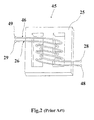
Figure 2 illustrates a traditional transformer (prior art); -
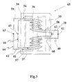
Figure 3 illustrates a SIP transformer according to the present invention; and -
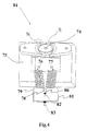
Figure 4 illustrates a SIP motor or a SIP generator according to the present invention. - The following descriptions are exemplary embodiments only, and are not intended to limit the scope, applicability or configuration of the invention in any way. Rather, the following description provides a convenient illustration for implementing exemplary embodiments of the invention. Various changes to the described embodiments may be made in the function and arrangement of the elements described without departing from the scope of the invention as set forth in the appended claims.
- A. Description of making SIP Induction Coils
A SIP Induction Coil includes a magnetic core and two conductive wires wound around the core (equal turns) symmetrically and connected in parallel.Coil 6 andcoil 7 are wound symmetrically and connected in parallel (wire ends 8 & 10 andwire ends 9 & 11) to form a SIP Induction Coil or a SIP Inductor as shown inFigure 1 . - B. Theoretical Principle:
Since a SIP Induction Coil is made of two coils wound symmetrically (1/2 turns per coil) and connected in parallel, the resistance of each coil (1/2 length of wound wire in a prior-art induction coil) is ½ resistance of the prior-art induction coil (single wire induction coil); therefore, the SIP Induction Coil in this case would show only ¼ resistance of the correspondent prior-art induction coil (single wire induction coil of an equal wire length). This unique feature can provide designers more design freedom such as selecting thinner wires with more turns in each coil for better performance and efficiency with many great benefits of less cupper loss, reduced temperature-rise (energy saving) and reduced size (volume) of the induction coils. The SIP Induction Coils can be applied to designing SIP Electromagnetic Devices (inductors, transformers, motors and generators). The unique features of the invention are reduced magnetization current, less cupper loss, less temperature-rise, better performance and efficiency with many benefits of energy savings, reduced size (volume) of electromagnetic devices and reduced cooling system if needed. - C. SIP Electromagnetic Devices Description:
- (1) SIP Inductors
Refer toFigure 1 , a SIP Inductor is made of two conductive wires wound symmetrically and connected in parallel. Resistance of theSIP Inductor 14 is only ¼ resistance of a correspondent prior-art inductor (equal wire size and length). For a specific inductance, a SIP Inductor can be designed by using thinner wire so that the SIP Inductor can have many benefits of less cupper loss, less temperature-rise, better performance and efficiency, and reduced size (volume) of the inductor. Inductors are used in wave filter, stabilizer of fluorescent light and others. SIP Inductors may contribute greatly to miniaturization of electromagnetic devices. - (2) SIP Transformers
Refer toFigure 2 , a prior-art transformer 45 consists of aprimary coil 26 wound on thecore 25 andsecondary coil 46 wound above theprimary coil 26.Primary coil 26 andsecondary coil 46 have several layers of turns respectively; the turns ratio of the primary coil and secondary coil determines the ratio of input voltage and output voltage. Refer toFigure 3 , aSIP Transformer 65 consists of a SIP Primary Coil 44 (coils 36 and 37) and a SIP Secondary Coil 64 (coils 56 and 57). There is an insulation between the SIPPrimary Coil 44 and the SIP Secondary Coil 64 (the insulation not shown inFigures 2 and3 ). Input power enters SIPPrimary Coil 44 and output power is from the SIPSecondary Coil 64. - (3) SIP Induction Motors
Refer toFigure 4 , aSIP Induction Motor 84 includes ashaft 74 and amagnetic core 75 on whichcoil 76 andcoil 77 are wound symmetrically and connected in parallel. A SIP Induction Motor has less cupper loss, lower temperature-rise, faster acceleration, reduced noise, better performance and higher efficiency than those of a correspondent traditional induction motor (prior art). - (4) SIP Generators
Refer toFigure 4 , aSIP Generator 84 includes ashaft 74 and amagnetic core 75 on whichcoils 76 andcoil 77 are wound symmetrically and connected in parallel. Whenshaft 74 starts revolving, it would generate electricity. A SIP Generator has lower temperature-rise, better performance and higher efficiency in generating electricity than a correspondent traditional generator (prior art).
- (1) SIP Inductors
- D. Some Test Data of a SIP Transformer and two traditional transformers (prior art)
- (1) A 3-volt SIP Transformer and a traditional 3-volt transformer (prior art)
A 3-volt traditional transformer includes a primary coil (125 Ohms) and a secondary coil (0.2 Ohm). Based on these specific resistances, a SIP Transformer can be designed as follows :- The SIP Primary Coil is made of two thinner conductive wire (1/2 wire size) whose unit resistance is 4 times unit resistance of the primary coil in the traditional transformer; the wire length of each coil in the SIP Primary Coil is 1/2 wire length of the primary coil in the traditional transformer so that each coil of the SIP Primary Coil has a 250-Ohm resistance. The SIP Primary Coil which is consist of two symmetrical coils connected in parallel has a 125-Ohm resistance same as that of the primary coil in the traditional transformer. The SIP Secondary Coil is similarly made of two thinner wire (1/2 wire size of the secondary coil in the traditional transformer) and each of the two coils has ½ wire length of the secondary coil in the traditional transformer. The SIP Secondary Coil has 0.2-Ohm resistance same as that of the secondary coil in the traditional transformer. Such a SIP Transformer has the benefits of reduced cupper loss, better performance, higher efficiency, lower temperature-rise and reduced volume.
- (2) Performance of a SIP Transformer and two traditional transformers
Refer to Tables 1a & 1b, under an 8-Ohm load and similar voltage ratio (120V/3.57V, 120V/3.88V), a traditional transformer has an input current 0.182A and output current 0.360A while the SIP Transformer has a 0.069A input current and an output current of 0.392A.
Refer to Table 1c (temperature measurements), the traditional transformer shows a range of 140-145.8 F during 30-120 minutes while the SIP Transformer shows a range of 104.5-108.7 F during 30-120 minutes. The SIP transformer shows a significantly lower temperatures during 30-120 minutes than those of the correspondent traditional standard transformer (prior art).
Refer to Table 2a, for the specific voltage ratio (120V/3V), a SIP Transformer has shown significantly lower input current and input power, and significantly higher efficiency than those of a traditional standard transformer (prior art). Refer to Table 2b (inductance measurements), The SIP Transformer shows higher inductances (2.17 H & 0.00279 H) across the SIP Primary Coil and across the SIP Secondary Coil than those (1.50 H & 0.00180 H) of the traditional standard transformer (prior art). The SIP Transformer shows higher leakage inductance (0.0263 H & 0.0000304 H) across the SIP Primary Coil and the SIP Secondary Coil than those (0.0167H & 0.0000170H) of the traditional standard Transformer (prior art).
Refer to Table 3a (No Load tests), the SIP Transformer shows significantly higher inductance (3.771 H & 0.03543 H) in the SIP Primary Coil and SIP Secondary Coil, significantly lower magnetization current (0.018795 A) and significantly lower input power (0.994 W) than those (0.681H & 0.003176H, 0.150148A, and 4.557 W) of the Square-D transformer (prior-art). Refer to Table 3b (Loaded tests), the SIP Transformer with Loads (10 & 4.7 Ohm) shows lower input current (0.11193 A & 0.21782 A), lower input power (13.298 W & 26.074 W) and higher efficiency (88.6% & 87.5%) than those (0.22050 A & 0.34856A, 20.473 W & 38.406 W and 77.5% & 84.9%) of the Square-D transformer (prior art).
- (1) A 3-volt SIP Transformer and a traditional 3-volt transformer (prior art)
- From the above tests (Tables 1a - 3b) on the SIP Transformer and two traditional transformers (prior art), they clearly show that the SIP Transformer has better performance, higher efficiency and many great benefits of reduced magnetization current, lower input current, lower input power, lower temperature-rise, higher inductances and higher leakage inductances across the primary coil and secondary coil than those of the traditional transformers (prior art). The invention of SIP Electromagnetic Devices can contribute greatly to the industries of electromagnetic devices in making electromagnetic devices with better performance & higher efficiency and many great benefits of more energy savings, reduced size (volume) of the electromagnetic devices and reduced cooling systems if needed.
Table 1a: Power Tests of a Standard Transformer (Prior Art) and a SIP Transformer Type of
TransformerLoad
(Ohm)Voltage In
(V)Current In
(A)Voltage Out
(V)Current Out
(A)Standard Transformer 8.0 60.0 0.018 1.80 0.185 SIP Transformer 8.0 60.0 0.012 1.93 0.196 Standard Transformer 8.0 120.0 0.182 3.57 0.360 SIP Transformer 8.0 120.0 0.069 3.88 0.392 Standard Transformer 4.0 120.0 0.1765 3.50 0.865 SIP Transformer 4.0 120.0 0.0710 3.75 0.925 Standard Transformer 1.5 120.0 0.1630 3.30 1.968 SIP Transformer 1.5 120.0 0.0905 3.44 2.050 Table 1b: Resistance Measurements of a Standard Transformer (Prior Art) and a SIP Transformer Type of Transformer Primary Coil Resistance (Ohm) Secondary Coil Resistance(Ohm) Standard Transformer 129.0 0.2 SIP Trnsformer 127.6 0.3 - Table 1c: Temperature Measurements of a Standard Transformer (Prior Art) and a SIP Transformer
- With 120 Vac into a Light Bulb (3-6 Vac)
Type of Transformer Time (minutes) Temperature (F) Standard Transformer 30 140.0 SIP Transformer 30 104.5 Standard Transformer 60 144.0 SIP Transformer 60 107.7 Standard Transformer 120 144.8 SIP Transformer 120 108.7 Table 2a: Power Measurements of a Standard Transformer (Prior Art) and a SIP Transformer Type of
TransformerInto
Load
(Ohm)Voltage
In
(Vac)Current
In
(A)Power
In
(W)Power
FactorVoltage
Out
(Vac)Current
Out
(A)Output
Power
(W)Efficiency
%Standard Transforms Light Bulb (3-6 Vac) 120.5 0.1884 6.39 0.2815 3.60 0.113 0.4070 6.37 SIP Transforms Light Bulb (3-6 Vac) 120.2 0.0689 1.63 0.1968 3.93 0.119 0.4677 28.69 Standard Transformer 8 120.4 0.1769 7.19 0.3376 3.47 0.443 1.5370 21.38 SIP Transformer 8 120.4 0.0685 2.98 0.3612 3.77 0.471 1.7757 59.59 Standard Transformer 4 120.3 0.16840 8.12 0.4008 3.30 0.85 2.8050 34.54 SIP Transformer 4 120.7 0.07137 4.78 0.5549 3.58 0.93 3.3294 69.65 Standard Transformer 1.5 120.4 0.1552 10.55 0.5646 2.94 1.884 5.5390 52.50 SIP Transformer 1.5 120.3 0.0885 8.90 0.8360 3.09 1.994 6.1615 69.23 Standard Transformer No Load 129.5 0.1860 5.70 SIP Transformer No Load 119.6 0.0686 1.13 Table 2b: Inductance Measurements of a Standard Transformer (Prior Art) and a SIP Transformer Type of Transformer Inductance (H) Across Primary Inductance (H) Across Secondary Standard Transformer 1.50 0.00180 SIP Transformer 2.17 0.00279 Type of Transformer Leakage Inductance (H) Across Primary Leakage Inductance (H) Across Secondary Standard Transformer 0.0167 0.0000170 SIP Transformer 0.0263 0.0000304 Table 3a: No Load Tests of a Square D Transformer (Prior Art) and a SIP Transformer Parameters Square D Transformer (Prior Art) SIP Transformer DC Primary Resistance (Ohm) 5.961 16.585 DC Secondary Resistance(Ohm) 0.1545 0.3223 Primary Inductance (H) 0.681 3.771 Secondary Inductance (H) 0.003176 0.03543 Turns Ratio 9.44 10.587 Leakage Inductance (H) 0.016965 0.022263 Magnetization Currant (A) 0.150148 0.018795 Primary Input Power (W) 4.557 0.994 Table 3b: Loaded Tests of a Square D Transformer (Prior Art) and a SIP Transformer Type of
TransformerLoad
(Ohm)Primary
Voltage
(V)Primary
Current
(A)Input
Power
(W)Secondary
Voltage
(V)Secondary
Current
(A)Output
Power
(W)Efficiency
(%)Square D Transformer 10 120 0.220497 20.473 12.602 1.259 15.870 77.5 SIP Transformer 10 120 0.111930 13.298 10.860 1.085 11.786 88.6 Square D Transformer 4.7 120 0.348562 38.406 12.340 2.642 32.610 84.9 SIP Transformer 4.7 120 0.217820 26.074 10.324 2.211 22.823 87.5 Square D Transformer 3.3 120 --- --- --- --- --- --- SIP Transformer 3.3 120 0.293510 35.170 9.956 3.011 29.973 85.2 Square D Transformer No Load 120 0.150148 4.557 SIP Transformer No Load 120 0.020140 0.994 - With the 3.3 Ohm load on the Square D Transformer, the power required exceeded the power supply of the AT3600 used (50W).
-
- 5: A magnetic core in
Fig. 1 (a SIP Induction Coil or a SIP Inductor) - 6: A coil wound around the core from the center toward one end and back to the center and repeating
winding cycles until the required number of turns are completed as shown inFig. 1 - 7: A second coil wound around the core from the center toward the other end and back to the center
and repeating winding cycles until the required number of turns are completed as shown inFig. 1 - 8: One end of
coil 6 shown inFig. 1 - 9: The other end of
coil 6 shown inFig. 1 - 10: One end of
coil 7 inFig. 1 - 11: The other end of
coil 7 inFig. 1 - 12: A lead of two symmetrically wound wire ends 8 & 10 connected in parallel in
Fig. 1 - 13: The other lead of two symmetrically wound wire ends 9 & 11 connected in parallel in
Fig. 1 - 14: A SIP Induction Coil or a SIP Inductor in
Fig. 1 - 25: The magnetic core of
Fig. 2 (a prior-art transformer) - 26: A primary coil in
Fig. 2 - 28: One end of the primary coil in
Fig. 2 . - 29: The other end of the primary coil in
Fig. 2 - 35: The magnetic core in
Fig. 3 (a SIP Transformer) - 36: One primary coil in
Fig. 3 - 37: The other primary coil in
Fig. 3 - 38: One end of the
primary coil 36 inFig. 3 - 39: The other end of the
primary coil 36 inFig. 3 - 40: One end of the
primary coil 37 inFig. 3 - 41: The other end of the
primary coil 37 inFig. 3 - 42: One lead of two symmetrical
primary coils 36 & 37 connected in parallel - 43: The other lead of two symmetrical
primary coils 36 & 37 connected in parallel inFig. 3 - 44: A SIP Primary Coil of two symmetrical
primary coils 36 & 37 connected in parallel inFig. 3 - 45: A traditional transformer (prior art) in
Fig. 2 - 46: The secondary coil in
Fig. 2 - 48: One end of the secondary coil in
Fig. 2 - 49: The other end of the secondary coil in
Fig. 2 - 56: One secondary coil in
Fig. 3 - 57: The other secondary coil in
Fig. 3 - 58: One end of the
secondary coil 56 inFig. 3 - 59: The other end of the
secondary coil 56 inFig. 3 - 60: One end of the
secondary coil 57 inFig. 3 - 61: The other end of the
secondary coil 57 inFig. 3 - 62: One lead of the secondary coil 64 (two
symmetrical wires 58 & 60 connected in parallel) inFig. 3 - 63: The other lead of the secondary coil 64 (two
symmetrical wires 59 & 61 connected in parallel) inFig. 3 - 64: A SIP Secondary Coil of two symmetrical
secondary coils 56 & 57 connected in parallel inFig. 3 - 65: A SIP Transformer in
Fig. 3 - 74: A shaft in a SIP Motor or a SIP Generator in
Fig. 4 - 75: A magnetic core in a SIP Motor or a SIP Generator in
Fig. 4 - 76: One coil is made of winding a conductive wire around the core in
Fig. 4 - 77: The other coil wound around the core symmetrically to
coil 76 inFig. 4 - 78: One end of
coil 76 inFig. 4 - 79: The other end of
coil 76 inFig. 4 - 80: One end of
coil 77 inFig. 4 - 81: The other end of
coil 77 inFig. 4 - 82: A lead of two symmetrically wound coils 76 & 77 connected in parallel in
Fig. 4 - 83: The other lead of two symmetrically wound coils 76 & 77 connected in parallel in
Fig. 4 - 84: A SIP Motor or a SIP Generator in
Fig. 4 - While certain novel features of this invention have been shown and described and are pointed out in the annexed claim, it is not intended to be limited to the details above, since it will be understood that various omissions, modifications, substitutions and changes in the forms and details of the device illustrated and in its operation can be made by those skilled in the art without departing in any way from the spirit of the present invention.
Claims (6)
- A SIP induction coil consists of winding two conductive wires symmetrically around a magnetic core from the center toward two ends and winding back to the center and repeating winding cycles until the required number of turns are completed and the two symmetrical coils are connected in parallel.
- A magnetic core for making a SIP induction coil in Claim 1, includes all kinds of magnetic materials and all shapes of the magnetic cores used in making all kinds of the traditional induction coils used in the traditional electromagnetic devices.
- A SIP induction coil comprises one pair or more pairs of SIP induction coils in Claim 1.
- A SIP electromagnetic device which contains one or more SIP Induction Coils in claim 1, containing the procedures of winding conductive wires Symmetrically and being connected In Parallel (SIP) includes SIP Inductors, SIP Transformers, SIP Motors and SIP Generators which correspond to all kinds of traditional inductors, traditional transformers, traditional motors and traditional generators.
- A SIP electromagnetic device which contains one or more SIP Induction Coils in claim 2, containing the procedures of winding conductive wires Symmetrically and being connected In Parallel (SIP) includes SIP Inductors, SIP Transformers, SIP Motors and SIP Generators which correspond to all kinds of traditional inductors, traditional transformers, traditional motors and traditional generators.
- A SIP electromagnetic device which contains one or more SIP induction coils in claim 3, containing the procedures of winding conductive wires symmetrically and being connected in parallel (SIP) includes SIP inductors, SIP transformers, SIP motors and SIP generators which correspond to all kinds of traditional inductors, traditional transformers, traditional motors and traditional generators.
Applications Claiming Priority (1)
| Application Number | Priority Date | Filing Date | Title |
|---|---|---|---|
| TW098134775A TW201113915A (en) | 2009-10-14 | 2009-10-14 | Symmetrical parallel induction coils for electromagnetic devices |
Publications (2)
| Publication Number | Publication Date |
|---|---|
| EP2312596A2 true EP2312596A2 (en) | 2011-04-20 |
| EP2312596A3 EP2312596A3 (en) | 2012-05-02 |
Family
ID=43480925
Family Applications (1)
| Application Number | Title | Priority Date | Filing Date |
|---|---|---|---|
| EP10187354A Withdrawn EP2312596A3 (en) | 2009-10-14 | 2010-10-13 | SIP (symmetrical-in-parallel) induction coils for electromagnetic devices |
Country Status (4)
| Country | Link |
|---|---|
| US (1) | US20110084792A1 (en) |
| EP (1) | EP2312596A3 (en) |
| JP (1) | JP3164981U (en) |
| TW (1) | TW201113915A (en) |
Families Citing this family (6)
| Publication number | Priority date | Publication date | Assignee | Title |
|---|---|---|---|---|
| JP6287678B2 (en) * | 2014-08-08 | 2018-03-07 | 株式会社豊田自動織機 | Coil parts |
| CN104300834A (en) * | 2014-09-25 | 2015-01-21 | 陈新培 | Novel magnetic energy electric generator |
| CN107642900A (en) * | 2017-10-10 | 2018-01-30 | 沈阳日月蓝天新能源科技有限公司 | A kind of magnet coil heat cycles wetting system |
| JP7057505B2 (en) * | 2018-08-29 | 2022-04-20 | 日本電信電話株式会社 | Repair device |
| CN112052569B (en) * | 2020-08-18 | 2024-04-05 | 保定天威集团特变电气有限公司 | Method and device for calculating loop current loss of transformer coil |
| CN112162225B (en) * | 2020-11-03 | 2024-01-05 | 苏州斯玛维科技有限公司 | Unilateral magnet structure |
Family Cites Families (23)
| Publication number | Priority date | Publication date | Assignee | Title |
|---|---|---|---|---|
| US2082121A (en) * | 1929-12-27 | 1937-06-01 | Albert B Rypinski | Slow magnetic regulating device |
| US1972319A (en) * | 1933-05-18 | 1934-09-04 | Albert B Rypinski | Coil for slow electromagnets and reactors |
| US2354332A (en) * | 1942-05-22 | 1944-07-25 | Wladimir J Polydoroff | Loop antenna |
| US2401882A (en) * | 1942-05-22 | 1946-06-11 | Rca Corp | Ultra high frequency inductor |
| US2495157A (en) * | 1948-08-17 | 1950-01-17 | Westinghouse Electric Corp | Electromagnetic device |
| US2741121A (en) * | 1952-06-17 | 1956-04-10 | Vitro Corp Of America | Means for minimizing electrostatic voltages in a flowmeter |
| US3392326A (en) * | 1966-09-28 | 1968-07-09 | Gen Electric | Coil winding buffer conductors having impedance means |
| US3624577A (en) * | 1969-10-17 | 1971-11-30 | Westinghouse Electric Corp | Tapped multilayer winding for electrical inductive apparatus |
| BE789869A (en) * | 1971-10-09 | 1973-04-09 | Philips Nv | COLOR TELEVISION IMAGE REPRODUCTION DEVICE, EQUIPPED WITH A CATHODIC TUBE |
| CA965166A (en) * | 1972-12-28 | 1975-03-25 | Trench Electric Limited | Air core duplex reactor |
| US4473811A (en) * | 1982-02-25 | 1984-09-25 | General Instrument Corporation | Single bobbin transformer having multiple delink windings and method of making same |
| JPS60250609A (en) * | 1984-05-28 | 1985-12-11 | S M K Kk | Impedance conversion transformer |
| US4806834A (en) * | 1987-04-16 | 1989-02-21 | Donald Goodman | Electrical circuit for inductance conductors, transformers and motors |
| US5200718A (en) * | 1990-10-23 | 1993-04-06 | Smk Co., Ltd. | Balun transformer with common mode coil |
| DE69417950T2 (en) * | 1993-05-26 | 1999-09-23 | Nippon Telegraph & Telephone | Filters to achieve electromagnetic compatibility for a symmetrical multi-core telecommunication line |
| DE19934767A1 (en) * | 1999-07-23 | 2001-01-25 | Philips Corp Intellectual Pty | Magnetic component |
| WO2003032477A2 (en) * | 2001-10-12 | 2003-04-17 | Northeastern University | Integrated magnetics for a dc-dc converter with flexible output inductor |
| US7123122B2 (en) * | 2003-04-18 | 2006-10-17 | Medtronic, Inc. | Center tapped chip inductor |
| CN100426637C (en) * | 2003-08-16 | 2008-10-15 | 鸿富锦精密工业(深圳)有限公司 | Direct-current brushless motor |
| US7161458B2 (en) * | 2005-02-22 | 2007-01-09 | Delta Electronics, Inc. | Electromagnetic device having independent inductive components |
| DE102006062205B4 (en) * | 2006-08-25 | 2012-07-19 | Minebea Co., Ltd. | High Voltage Transformer |
| JP4674590B2 (en) * | 2007-02-15 | 2011-04-20 | ソニー株式会社 | Balun transformer, balun transformer mounting structure, and electronic device incorporating the mounting structure |
| US7982572B2 (en) * | 2008-07-17 | 2011-07-19 | Pulse Engineering, Inc. | Substrate inductive devices and methods |
-
2009
- 2009-10-14 TW TW098134775A patent/TW201113915A/en unknown
-
2010
- 2010-10-12 US US12/903,179 patent/US20110084792A1/en not_active Abandoned
- 2010-10-13 EP EP10187354A patent/EP2312596A3/en not_active Withdrawn
- 2010-10-13 JP JP2010006793U patent/JP3164981U/en not_active Expired - Fee Related
Non-Patent Citations (1)
| Title |
|---|
| None |
Also Published As
| Publication number | Publication date |
|---|---|
| EP2312596A3 (en) | 2012-05-02 |
| US20110084792A1 (en) | 2011-04-14 |
| TW201113915A (en) | 2011-04-16 |
| JP3164981U (en) | 2010-12-24 |
Similar Documents
| Publication | Publication Date | Title |
|---|---|---|
| EP2312596A2 (en) | SIP (symmetrical-in-parallel) induction coils for electromagnetic devices | |
| JP4800451B1 (en) | High frequency transformer | |
| RU2481662C2 (en) | Flat coil | |
| US9633776B2 (en) | Variable core electromagnetic device | |
| JP5813320B2 (en) | High frequency transformer for high voltage applications | |
| WO2012136754A1 (en) | Cable and electromagnetic device comprising the same | |
| JP2011187600A (en) | Electromagnetic coil device and transformer | |
| Loef et al. | On high frequency high voltage generators with planar transformers | |
| CN116095895A (en) | Battery cell heating device and lithium battery equipment | |
| JPH11243019A (en) | Transformer | |
| US10186370B1 (en) | Transformers with integrated inductors | |
| CN215933343U (en) | Voltage regulating assembly for power transformer | |
| WO2010136033A1 (en) | Converter system for a wind turbine | |
| JP6782891B2 (en) | Transformer and resonant converter using it | |
| US20140085757A1 (en) | Surge blocking inductor | |
| US7528692B2 (en) | Voltage stress reduction in magnetics using high resistivity materials | |
| JP6236853B2 (en) | Hollow tubular reactor device, hollow tubular converter device, and hollow tubular power supply device | |
| GB2597477A (en) | Inductive coil assembly | |
| CN202394669U (en) | Wire cake and transformer using same | |
| CN112530682A (en) | Inductor structure having multiple windings with uncoupled magnetic fields | |
| Mohamadi et al. | Airgap-less integrated magnetic array using high performance magnetic material in the EV chargers | |
| Wang et al. | Design of multi-permeability distributed air-gap inductors | |
| CN211858327U (en) | Inductance structure, reactance device and transformer device | |
| CN102063999A (en) | Symmetrically parallel induction coil applied to electromagnetic equipment | |
| US11909284B2 (en) | Flat-type stator with multilayer coils for disc-type motor |
Legal Events
| Date | Code | Title | Description |
|---|---|---|---|
| PUAI | Public reference made under article 153(3) epc to a published international application that has entered the european phase |
Free format text: ORIGINAL CODE: 0009012 |
|
| 17P | Request for examination filed |
Effective date: 20101018 |
|
| AK | Designated contracting states |
Kind code of ref document: A2 Designated state(s): AL AT BE BG CH CY CZ DE DK EE ES FI FR GB GR HR HU IE IS IT LI LT LU LV MC MK MT NL NO PL PT RO RS SE SI SK SM TR |
|
| AX | Request for extension of the european patent |
Extension state: BA ME |
|
| PUAL | Search report despatched |
Free format text: ORIGINAL CODE: 0009013 |
|
| AK | Designated contracting states |
Kind code of ref document: A3 Designated state(s): AL AT BE BG CH CY CZ DE DK EE ES FI FR GB GR HR HU IE IS IT LI LT LU LV MC MK MT NL NO PL PT RO RS SE SI SK SM TR |
|
| AX | Request for extension of the european patent |
Extension state: BA ME |
|
| RIC1 | Information provided on ipc code assigned before grant |
Ipc: H03H 7/42 20060101ALI20120327BHEP Ipc: H01F 29/02 20060101ALI20120327BHEP Ipc: H01F 27/29 20060101ALI20120327BHEP Ipc: H01F 21/12 20060101ALI20120327BHEP Ipc: H01F 7/06 20060101ALI20120327BHEP Ipc: H01F 5/00 20060101ALI20120327BHEP Ipc: H02K 21/18 20060101ALI20120327BHEP Ipc: H02K 3/28 20060101ALI20120327BHEP Ipc: H01F 41/06 20060101ALI20120327BHEP Ipc: H01F 27/34 20060101ALI20120327BHEP Ipc: H01F 17/04 20060101AFI20120327BHEP |
|
| 17Q | First examination report despatched |
Effective date: 20130925 |
|
| STAA | Information on the status of an ep patent application or granted ep patent |
Free format text: STATUS: THE APPLICATION IS DEEMED TO BE WITHDRAWN |
|
| 18D | Application deemed to be withdrawn |
Effective date: 20131206 |