EP2316802A1 - Coated article with low-e coating including tin oxide interlayer - Google Patents
Coated article with low-e coating including tin oxide interlayer Download PDFInfo
- Publication number
- EP2316802A1 EP2316802A1 EP10178277A EP10178277A EP2316802A1 EP 2316802 A1 EP2316802 A1 EP 2316802A1 EP 10178277 A EP10178277 A EP 10178277A EP 10178277 A EP10178277 A EP 10178277A EP 2316802 A1 EP2316802 A1 EP 2316802A1
- Authority
- EP
- European Patent Office
- Prior art keywords
- layer
- coated article
- heat treatment
- minute mark
- contacting
- Prior art date
- Legal status (The legal status is an assumption and is not a legal conclusion. Google has not performed a legal analysis and makes no representation as to the accuracy of the status listed.)
- Withdrawn
Links
Images
Classifications
-
- C—CHEMISTRY; METALLURGY
- C03—GLASS; MINERAL OR SLAG WOOL
- C03C—CHEMICAL COMPOSITION OF GLASSES, GLAZES OR VITREOUS ENAMELS; SURFACE TREATMENT OF GLASS; SURFACE TREATMENT OF FIBRES OR FILAMENTS MADE FROM GLASS, MINERALS OR SLAGS; JOINING GLASS TO GLASS OR OTHER MATERIALS
- C03C17/00—Surface treatment of glass, not in the form of fibres or filaments, by coating
- C03C17/34—Surface treatment of glass, not in the form of fibres or filaments, by coating with at least two coatings having different compositions
- C03C17/36—Surface treatment of glass, not in the form of fibres or filaments, by coating with at least two coatings having different compositions at least one coating being a metal
-
- C—CHEMISTRY; METALLURGY
- C03—GLASS; MINERAL OR SLAG WOOL
- C03C—CHEMICAL COMPOSITION OF GLASSES, GLAZES OR VITREOUS ENAMELS; SURFACE TREATMENT OF GLASS; SURFACE TREATMENT OF FIBRES OR FILAMENTS MADE FROM GLASS, MINERALS OR SLAGS; JOINING GLASS TO GLASS OR OTHER MATERIALS
- C03C17/00—Surface treatment of glass, not in the form of fibres or filaments, by coating
- C03C17/22—Surface treatment of glass, not in the form of fibres or filaments, by coating with other inorganic material
- C03C17/23—Oxides
-
- C—CHEMISTRY; METALLURGY
- C03—GLASS; MINERAL OR SLAG WOOL
- C03C—CHEMICAL COMPOSITION OF GLASSES, GLAZES OR VITREOUS ENAMELS; SURFACE TREATMENT OF GLASS; SURFACE TREATMENT OF FIBRES OR FILAMENTS MADE FROM GLASS, MINERALS OR SLAGS; JOINING GLASS TO GLASS OR OTHER MATERIALS
- C03C17/00—Surface treatment of glass, not in the form of fibres or filaments, by coating
- C03C17/34—Surface treatment of glass, not in the form of fibres or filaments, by coating with at least two coatings having different compositions
- C03C17/36—Surface treatment of glass, not in the form of fibres or filaments, by coating with at least two coatings having different compositions at least one coating being a metal
- C03C17/3602—Surface treatment of glass, not in the form of fibres or filaments, by coating with at least two coatings having different compositions at least one coating being a metal the metal being present as a layer
- C03C17/3618—Coatings of type glass/inorganic compound/other inorganic layers, at least one layer being metallic
-
- C—CHEMISTRY; METALLURGY
- C03—GLASS; MINERAL OR SLAG WOOL
- C03C—CHEMICAL COMPOSITION OF GLASSES, GLAZES OR VITREOUS ENAMELS; SURFACE TREATMENT OF GLASS; SURFACE TREATMENT OF FIBRES OR FILAMENTS MADE FROM GLASS, MINERALS OR SLAGS; JOINING GLASS TO GLASS OR OTHER MATERIALS
- C03C17/00—Surface treatment of glass, not in the form of fibres or filaments, by coating
- C03C17/34—Surface treatment of glass, not in the form of fibres or filaments, by coating with at least two coatings having different compositions
- C03C17/36—Surface treatment of glass, not in the form of fibres or filaments, by coating with at least two coatings having different compositions at least one coating being a metal
- C03C17/3602—Surface treatment of glass, not in the form of fibres or filaments, by coating with at least two coatings having different compositions at least one coating being a metal the metal being present as a layer
- C03C17/3626—Surface treatment of glass, not in the form of fibres or filaments, by coating with at least two coatings having different compositions at least one coating being a metal the metal being present as a layer one layer at least containing a nitride, oxynitride, boronitride or carbonitride
-
- C—CHEMISTRY; METALLURGY
- C03—GLASS; MINERAL OR SLAG WOOL
- C03C—CHEMICAL COMPOSITION OF GLASSES, GLAZES OR VITREOUS ENAMELS; SURFACE TREATMENT OF GLASS; SURFACE TREATMENT OF FIBRES OR FILAMENTS MADE FROM GLASS, MINERALS OR SLAGS; JOINING GLASS TO GLASS OR OTHER MATERIALS
- C03C17/00—Surface treatment of glass, not in the form of fibres or filaments, by coating
- C03C17/34—Surface treatment of glass, not in the form of fibres or filaments, by coating with at least two coatings having different compositions
- C03C17/36—Surface treatment of glass, not in the form of fibres or filaments, by coating with at least two coatings having different compositions at least one coating being a metal
- C03C17/3602—Surface treatment of glass, not in the form of fibres or filaments, by coating with at least two coatings having different compositions at least one coating being a metal the metal being present as a layer
- C03C17/3639—Multilayers containing at least two functional metal layers
-
- C—CHEMISTRY; METALLURGY
- C03—GLASS; MINERAL OR SLAG WOOL
- C03C—CHEMICAL COMPOSITION OF GLASSES, GLAZES OR VITREOUS ENAMELS; SURFACE TREATMENT OF GLASS; SURFACE TREATMENT OF FIBRES OR FILAMENTS MADE FROM GLASS, MINERALS OR SLAGS; JOINING GLASS TO GLASS OR OTHER MATERIALS
- C03C17/00—Surface treatment of glass, not in the form of fibres or filaments, by coating
- C03C17/34—Surface treatment of glass, not in the form of fibres or filaments, by coating with at least two coatings having different compositions
- C03C17/36—Surface treatment of glass, not in the form of fibres or filaments, by coating with at least two coatings having different compositions at least one coating being a metal
- C03C17/3602—Surface treatment of glass, not in the form of fibres or filaments, by coating with at least two coatings having different compositions at least one coating being a metal the metal being present as a layer
- C03C17/3644—Surface treatment of glass, not in the form of fibres or filaments, by coating with at least two coatings having different compositions at least one coating being a metal the metal being present as a layer the metal being silver
-
- C—CHEMISTRY; METALLURGY
- C03—GLASS; MINERAL OR SLAG WOOL
- C03C—CHEMICAL COMPOSITION OF GLASSES, GLAZES OR VITREOUS ENAMELS; SURFACE TREATMENT OF GLASS; SURFACE TREATMENT OF FIBRES OR FILAMENTS MADE FROM GLASS, MINERALS OR SLAGS; JOINING GLASS TO GLASS OR OTHER MATERIALS
- C03C17/00—Surface treatment of glass, not in the form of fibres or filaments, by coating
- C03C17/34—Surface treatment of glass, not in the form of fibres or filaments, by coating with at least two coatings having different compositions
- C03C17/36—Surface treatment of glass, not in the form of fibres or filaments, by coating with at least two coatings having different compositions at least one coating being a metal
- C03C17/3602—Surface treatment of glass, not in the form of fibres or filaments, by coating with at least two coatings having different compositions at least one coating being a metal the metal being present as a layer
- C03C17/3652—Surface treatment of glass, not in the form of fibres or filaments, by coating with at least two coatings having different compositions at least one coating being a metal the metal being present as a layer the coating stack containing at least one sacrificial layer to protect the metal from oxidation
-
- C—CHEMISTRY; METALLURGY
- C03—GLASS; MINERAL OR SLAG WOOL
- C03C—CHEMICAL COMPOSITION OF GLASSES, GLAZES OR VITREOUS ENAMELS; SURFACE TREATMENT OF GLASS; SURFACE TREATMENT OF FIBRES OR FILAMENTS MADE FROM GLASS, MINERALS OR SLAGS; JOINING GLASS TO GLASS OR OTHER MATERIALS
- C03C17/00—Surface treatment of glass, not in the form of fibres or filaments, by coating
- C03C17/34—Surface treatment of glass, not in the form of fibres or filaments, by coating with at least two coatings having different compositions
- C03C17/36—Surface treatment of glass, not in the form of fibres or filaments, by coating with at least two coatings having different compositions at least one coating being a metal
- C03C17/3602—Surface treatment of glass, not in the form of fibres or filaments, by coating with at least two coatings having different compositions at least one coating being a metal the metal being present as a layer
- C03C17/3657—Surface treatment of glass, not in the form of fibres or filaments, by coating with at least two coatings having different compositions at least one coating being a metal the metal being present as a layer the multilayer coating having optical properties
- C03C17/366—Low-emissivity or solar control coatings
-
- C—CHEMISTRY; METALLURGY
- C03—GLASS; MINERAL OR SLAG WOOL
- C03C—CHEMICAL COMPOSITION OF GLASSES, GLAZES OR VITREOUS ENAMELS; SURFACE TREATMENT OF GLASS; SURFACE TREATMENT OF FIBRES OR FILAMENTS MADE FROM GLASS, MINERALS OR SLAGS; JOINING GLASS TO GLASS OR OTHER MATERIALS
- C03C2217/00—Coatings on glass
- C03C2217/70—Properties of coatings
- C03C2217/78—Coatings specially designed to be durable, e.g. scratch-resistant
-
- Y—GENERAL TAGGING OF NEW TECHNOLOGICAL DEVELOPMENTS; GENERAL TAGGING OF CROSS-SECTIONAL TECHNOLOGIES SPANNING OVER SEVERAL SECTIONS OF THE IPC; TECHNICAL SUBJECTS COVERED BY FORMER USPC CROSS-REFERENCE ART COLLECTIONS [XRACs] AND DIGESTS
- Y10—TECHNICAL SUBJECTS COVERED BY FORMER USPC
- Y10T—TECHNICAL SUBJECTS COVERED BY FORMER US CLASSIFICATION
- Y10T428/00—Stock material or miscellaneous articles
- Y10T428/24—Structurally defined web or sheet [e.g., overall dimension, etc.]
- Y10T428/24942—Structurally defined web or sheet [e.g., overall dimension, etc.] including components having same physical characteristic in differing degree
- Y10T428/2495—Thickness [relative or absolute]
- Y10T428/24967—Absolute thicknesses specified
- Y10T428/24975—No layer or component greater than 5 mils thick
Definitions
- This invention relates to a coated article including a low-E coating.
- an interlayer comprising tin oxide or the like may be provided under an infrared (IR) reflecting layer and in particular between respective layers comprising silicon nitride and zinc oxide.
- the coated article may be heat treated (e.g., thermally tempered, heat bent and/or heat strengthened).
- Coated articles according to certain example embodiments of this invention may be used in the context of insulating glass (IG) window units, vehicle windows, other types of windows, or in any other suitable application.
- IG insulating glass
- Coated articles are known in the art for use in window applications such as insulating glass (IG) window units, vehicle windows, and/or the like. It is known that in certain instances, it is desirable to heat treat (e.g., thermally temper, heat bend and/or heat strengthen) such coated articles for purposes of tempering, bending, or the like in certain example instances.
- heat treat e.g., thermally temper, heat bend and/or heat strengthen
- heat treatment of coated articles typically requires use of temperature(s) of at least 580 degrees C, more preferably of at least about 600 degrees C and still more preferably of at least 620 degrees C.
- the use of such high temperatures e.g., for 5-10 minutes or more
- Those in the art strive for heat treatability in certain applications, coupled with acceptable optical and solar characteristics.
- the aforesaid coated article is susceptible to scratching in certain instances, and is also sometimes characterized by high haze values following heat treatment.
- coated articles which are capable of realizing (a) improved thermal stability with regard to visible transmission, color, emissivity (or emittance), and/or sheet resistance (R s ); (b) improved mechanical durability such as scratch resistance; and/or (c) improved haze characteristics. In certain example embodiments, it may be desired that one or all of these characteristics can be achieved.
- an interlayer comprising tin oxide is provided under an infrared (IR) reflecting layer so as to be located between respective layers comprising silicon nitride and zinc oxide.
- IR infrared
- tin oxide inclusive interlayer results in a coated article which is capable of realizing one or more of: (a) less visible transmission shift due to heat treatment, (b) higher visible transmission following heat treatment; (c) less shifting of certain color value(s) due to heat treatment, (d) substantially neutral coloration following heat treatment; (e) more stable, or even decreasing, sheet resistance due to heat treatment, (f) lower sheet resistance and thus lower emissivity following heat treatment, and/or (g) improved haze characteristics following heat treatment. It has also been found that the provision of this tin oxide inclusive interlayer is also capable of significantly improving mechanical durability and haze characteristics of the coated article, compared to if the layer were not present.
- a coated article comprising a coating supported by a glass substrate, the coating comprising: a first dielectric layer; a first infrared (IR) reflecting layer comprising silver located over at least the dielectric layer; a first layer comprising silicon nitride located over at least the first IR reflecting layer and the first dielectric layer; a first layer comprising tin oxide located over and contacting the first layer comprising silicon nitride; a first layer comprising zinc oxide located over and contacting the first layer comprising tin oxide, so that the first layer comprising tin oxide is located between and contacting the first layer comprising silicon nitride and the first layer comprising zinc oxide; a second IR reflecting layer comprising silver located over and contacting the first layer comprising zinc oxide; and at least another dielectric layer located over at least the second IR reflecting layer.
- IR infrared
- a coated article comprising a coating supported by a glass substrate, the coating comprising from the glass substrate outwardly: a layer comprising silicon nitride; a layer comprising tin oxide located over and contacting the layer comprising silicon nitride; a layer comprising zinc oxide located over and contacting the layer comprising tin oxide, so that the layer comprising tin oxide is located between and contacting the layer comprising silicon nitride and the layer comprising zinc oxide; an infrared (IR) reflecting layer located over and contacting the layer comprising zinc oxide; and at least another dielectric layer located over at least the IR reflecting layer.
- IR infrared
- a coated article including: a coating supported by a glass substrate, wherein the coating comprises first and second IR reflecting layers comprising silver which are spaced apart from one another by at least one layer comprising tin oxide, and wherein the coated article is capable of being heat treated for 18 minutes at a furnace temperature of about 650 degrees C without realizing a sheet resistance increase of more than 0.1 ohms/square and/or a visible transmission decrease of more than 1% from the 8 minute mark to the 18 minute mark of such heat treatment, measured monolithically.
- a coated article including: a coating supported by a glass substrate, wherein the coating comprises first and second IR reflecting layers comprising silver which are spaced apart from one another by at least one layer comprising tin oxide, and wherein the coated article is capable of being heat treated at a furnace temperature of about 650 degrees C for 12 minutes, and realizing at least one of the following due to such heat treatment: (a) a visible transmission that does not decrease between the 8 and 12 minute marks of such heat treatment; (b) a transmissive b* value which does not change by more than 0.5 from the 8 minute mark to the 12 minute mark of such heat treatment; and (c) a sheet resistance in units of ohms/square which does not increase from the 8 minute mark to the 12 minute mark of such heat treatment.
- a coated article comprising a coating supported by a glass substrate, the coating comprising: a first dielectric layer; a first infrared (IR) reflecting layer comprising silver located over at least the dielectric layer; a first layer comprising silicon nitride located over at least the first IR reflecting layer and the first dielectric layer; a first layer comprising a metal oxide located over and contacting the first layer comprising silicon nitride; a first layer comprising zinc oxide located over and contacting the first layer comprising the metal oxide, so that the first layer comprising the metal oxide is located between and contacting the first layer comprising silicon nitride and the first layer comprising zinc oxide; a second IR reflecting layer comprising silver located over and contacting the first layer comprising zinc oxide; and at least another dielectric layer located over at least the second IR reflecting layer.
- IR infrared
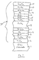
- FIGURE 1 is a cross sectional view of a coated article according to an example embodiment of this invention.
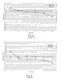
- FIGURE 2 is graph comparing changes in visible transmission (Ill. C, 2 degree obs.) due to heat treatment for an example embodiment of this invention versus a Comparative Example (CE).
- FIGURE 3 is graph comparing changes in transmissive b* coloration (Ill. C, 2 degree obs.) due to heat treatment for an example embodiment of this invention versus the Comparative Example (CE).
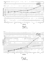
- FIGURE 4 is graph comparing changes in sheet resistance due to heat treatment for an example embodiment of this invention versus the Comparative Example (CE).
- FIGURE 5 is graph comparing changes in transmitted haze due to heat treatment for an example embodiment of this invention versus the Comparative Example (CE).
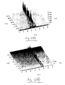
- FIGURES 6(a) and 6(b) are surface morphology images illustrating improved scratch resistance of an Example of this invention compared to a Comparative Example (CE).
- Coated articles herein may be used in applications such as IG window units, vehicle windows, monolithic architectural windows, residential windows, and/or any other suitable application that includes single or multiple glass substrates.
- an interlayer comprising tin oxide or the like is provided under an infrared (IR) reflecting layer.
- the interlayer comprising tin oxide is located between respective layers comprising silicon nitride and zinc oxide.
- improved mechanical durability, thermal stability and/or corrosion resistance for heat-treatable low-E coated articles can be realized when thermodynamically stable silver based layers are deposited, and the use of the tin oxide is believed to aid in providing such silver based layers even though the tin oxide is not in direct contact with the silver in certain example embodiments of this invention. It is believed that the tin oxide may reduce damage to the zinc oxide which may otherwise be caused by silicon nitride directly contacting the zinc oxide in certain instances.
- tin oxide inclusive interlayer results in a coated article which is capable of realizing one or more of: (a) less visible transmission shift due to heat treatment, (b) higher visible transmission following heat treatment; (c) less shifting of certain color value(s) due to heat treatment, (d) substantially neutral coloration following heat treatment; (e) more stable, or even decreasing, sheet resistance due to heat treatment, (f) lower sheet resistance and thus lower emissivity following heat treatment, and/or (g) improved haze characteristics following heat treatment. Scratch resistance is also remarkably improved as shown in Figs. 6(a)-(b) .
- the coating includes a double-silver stack, although this invention is not so limited in all instances.
- heat treated coated articles having multiple IR reflecting layers are capable of realizing a sheet resistance (R s ) of less than or equal to 3.0 (more preferably less than or equal to 2.5, even more preferably less than or equal to 2.1, and most preferably less than or equal to 2.0).
- coated articles herein are capable of realizing a visible transmission (Ill. C, 2 degree) of at least 75%, more preferably of at least 77%, and most preferably of at least 78%.
- IG window unit coated articles are capable of realizing a visible transmission of at least 60%, more preferably of at least 65%, even more preferably of at least 66%, and in certain embodiments of at least 67%.
- heat treatment and "heat treating” as used herein mean heating the article to a temperature sufficient to achieve thermal tempering, heat bending, and/or heat strengthening of the glass inclusive article.
- This definition includes, for example, heating a coated article in an oven or furnace at a temperature of least about 580 degrees C, more preferably at least about 600 degrees C, for a sufficient period to allow tempering, bending, and/or heat strengthening.
- the HT may be for at least about 4 or 5 minutes.
- Figure 1 is a side cross sectional view of a coated article according to an example non-limiting embodiment of this invention.
- the coated article includes substrate 1 (e.g., clear, green, bronze, or blue-green glass substrate from about 1.0 to 10.0 mm thick, more preferably from about 1.0 mm to 3.5 mm thick), and coating (or layer system) 30 provided on the substrate 1 either directly or indirectly.
- substrate 1 e.g., clear, green, bronze, or blue-green glass substrate from about 1.0 to 10.0 mm thick, more preferably from about 1.0 mm to 3.5 mm thick
- coating (or layer system) 30 provided on the substrate 1 either directly or indirectly.
- the coating (or layer system) 30 includes: bottom dielectric layer 2 which may be of or include titanium oxide (e.g., TiO 2 ) or the like, dielectric silicon nitride layer 3 which may be Si 3 N 4 , of the Si-rich type for haze reduction, or of any other suitable stoichiometry in different embodiments of this invention, first lower contact layer 7 (which contacts IR reflecting layer 9), first conductive and preferably metallic infrared (IR) reflecting layer 9, first upper contact layer 11 (which contacts layer 9), dielectric layer 13 (which may be deposited in one or multiple steps in different embodiments of this invention), another silicon nitride layer 14, tin oxide inclusive interlayer 15, second lower contact layer 17 (which contacts IR reflecting layer 19), second conductive and preferably metallic IR reflecting layer 19, second upper contact layer 21 (which contacts layer 19), dielectric layer 23, and finally protective dielectric layer 25.
- bottom dielectric layer 2 which may be of or include titanium oxide (e.g., TiO 2 ) or the like
- the "contact” layers 7, 11, 17 and 21 each contact at least one IR reflecting layer (e.g., layer based on Ag).
- the aforesaid layers 2-25 make up low-E (i.e., low emissivity) coating 30 which is provided on glass or plastic substrate 1.
- the coated article includes only one glass substrate 1 as illustrated in Fig. 1 .
- monolithic coated articles herein may be used in devices such as laminated vehicle windshields, IG window units, and the like.
- a laminated vehicle window such as a windshield typically includes first and second glass substrates laminated to one another via a polymer based interlayer (e.g., see US 6,686,050 , the disclosure of which is incorporated herein by reference).
- One of these substrates of the laminate may support coating 30 on an interior surface thereof in certain example embodiments.
- an IG window unit may include two spaced apart substrates.
- An example IG window unit is illustrated and described, for example, in U.S. Patent No.
- An example IG window unit may include, for example, the coated glass substrate 1 shown in Fig. 1 coupled to another glass substrate via spacer(s), sealant(s) or the like with a gap being defined therebetween.
- This gap between the substrates in IG unit embodiments may in certain instances be filled with a gas such as argon (Ar).
- An example IG unit may comprise a pair of spaced apart clear glass substrates each about 4 mm thick, one of which is coated with a coating 30 herein in certain example instances, where the gap between the substrates may be from about 5 to 30 mm, more preferably from about 10 to 20 mm, and most preferably about 16 mm.
- the coating 30 may be provided on the interior surface of either substrate facing the gap.
- Dielectric layer 2 is in direct contact with the glass substrate 1, and is optional.
- Dielectric layer 2 may be of or include TiO x in certain example embodiments of this invention, where x i2 from 1.5 to 2.0, more preferably about 2.0.
- Dielectric layers 3 and 14 may be of or include silicon nitride in certain embodiments of this invention. Silicon nitride layers 3 and 14 may, among other things, improve heat-treatability of the coated articles, e.g., such as thermal tempering or the like.
- the silicon nitride of layers 3 and/or 14 may be of the stoichiometric type (i.e., Si 3 N 4 ), or alternatively of the Si-rich type in different embodiments of this invention.
- Si-rich silicon nitride 3 (and/or 14) combined with zinc oxide and/or tin oxide under a silver based IR reflecting layer may permit the silver to be deposited (e.g., via sputtering or the like) in a manner which causes its sheet resistance to be lessened compared to if certain other material(s) were under the silver.
- the presence of free Si in a Si-rich silicon nitride inclusive layer 3 may allow certain atoms such as sodium (Na) which migrate outwardly from the glass 1 during HT to be more efficiently stopped by the Si-rich silicon nitride inclusive layer before they can reach the silver and damage the same.
- the oxidation caused by heat treatment allows visible transmission to increase, and that the Si-rich Si x N y in layer 3 can reduce the amount of damage done to the silver layer(s) during HT in certain example embodiments of this invention thereby allowing sheet resistance (R s ) to decrease or remain about the same in a satisfactory manner.
- the Si-rich silicon nitride layer as deposited may be characterized by Si x N y layer(s), where x/y may be from 0.76 to 1.5, more preferably from 0.8 to 1.4, still more preferably from 0.85 to 1.2.
- the Si-rich Si x N y layer(s) may have an index of refraction "n" of at least 2.05, more preferably of at least 2.07, and sometimes at least 2.10 (e.g., 632 nm) (note: stoichiometric Si 3 N 4 which may also be used has an index "n" of 2.02-2.04).
- the Si-rich Si x N y layer(s) as deposited has an index of refraction "n" of at least 2.10, more preferably of at least 2.20, and most preferably from 2.2 to 2.4.
- the Si-rich Si x N y layer in certain example embodiments may have an extinction coefficient "k" of at least 0.001, more preferably of at least 0.003 (note: stoichiometric Si 3 N 4 has an extinction coefficient "k” of effectively 0).
- any and/or all of the silicon nitride layers discussed herein may be doped with other materials such as stainless steel or aluminum in certain example embodiments of this invention.
- any and/or all silicon nitride layers discussed herein may optionally include from about 0-15% aluminum, more preferably from about 1 to 10% aluminum, in certain example embodiments of this invention.
- the silicon nitride may be deposited by sputtering a target of Si or SiAl in certain embodiments of this invention.
- Infrared (IR) reflecting layers 9 and 19 are preferably substantially or entirely metallic and/or conductive, and may comprise or consist essentially of silver (Ag), gold, or any other suitable IR reflecting material. IR reflecting layers 9 and 19 help allow the coating to have low-E and/or good solar control characteristics. The IR reflecting layers may, however, be slightly oxidized in certain embodiments of this invention.
- the upper contact layers 11 and 21 may be of or include nickel (Ni) oxide, chromium/chrome (Cr) oxide, or a nickel alloy oxide such as nickel chrome oxide (NiCrO x ), or other suitable material(s), in certain example embodiments of this invention.
- NiCrO x nickel chrome oxide
- the use of, for example, NiCrO x in these layers (11 and/or 21) allows durability to be improved.
- the NiCrO x of layers 11 and/or 21 may be fully oxidized in certain embodiments of this invention (i.e., fully stoichiometric), or alternatively may only be partially oxidized. In certain instances, the NiCrO x layers 11 and/or 21 may be at least about 50% oxidized.
- Contact layers 11 and/or 21 may or may not be oxidation graded in different embodiments of this invention.
- Oxidation grading means that the degree of oxidation in the layer changes throughout the thickness of the layer so that for example a contact layer may be graded so as to be less oxidized at the contact interface with the immediately adjacent IR reflecting layer than at a portion of the contact layer(s) further or more/most distant from the immediately adjacent IR reflecting layer.
- Descriptions of various types of oxidation graded contact layers are set forth in U.S. Patent No. 6,576,349 , the disclosure of which is hereby incorporated herein by reference.
- Contact layers 11 and/or 21 e.g., of or including an oxide of Ni and/or Cr
- Dielectric layer 13 may be of or include tin oxide in certain example embodiments of this invention. However, as with other layers herein, other materials may be used in different instances.
- Lower contact layers 7 and/or 17 in certain embodiments of this invention are of or include zinc oxide (e.g., ZnO).
- the zinc oxide of layers 7 and 17 may contain other materials as well such as Al (e.g., to form ZnAlO x ).
- one or more of zinc oxide layers 7, 17 may be doped with from about 1 to 10% Al, more preferably from about 1 to 5% Al, and most preferably about 1 to 4% Al.
- Interlayer 15 of or including tin oxide is provided under IR reflecting layer 19 so as to be located between silicon nitride layer 14 and zinc oxide layer 17.
- tin oxide inclusive interlayer 15 results in a coated article which is capable of realizing: (a) less visible transmission shift due to heat treatment, (b) higher visible transmission following heat treatment; (c) less shifting of certain color value(s) due to heat treatment, (d) substantially neutral coloration following heat treatment; (e) more stable, or even decreasing, sheet resistance due to heat treatment, (f) lower sheet resistance and thus lower emissivity following heat treatment, (g) improved haze characteristics following heat treatment, and/or (h) improved mechanical durability such as scratch resistance before and/or after heat treatment.
- coated articles may be taken to higher temperatures during heat treatment and/or for longer times without suffering undesirable significant transmission drops and/or increases in sheet resistance.
- other metal oxide(s) may be used for layer 15 in certain instances.
- Dielectric layer 23 may be of or include tin oxide in certain example embodiments of this invention. However, layer 23 is optional and need not be provided in certain example embodiments of this invention.
- Dielectric layer 25, which may be an overcoat in certain example instances, may be of or include silicon nitride (e.g., Si 3 N 4 ) or any other suitable material in certain example embodiments of this invention.
- other layers may be provided above layer 25.
- Layer 25 is provided for durability purposes, and to protect the underlying layers during heat treatment and/or environmental use.
- layer 25 may have an index of refraction (n) of from about 1.9 to 2.2, more preferably from about 1.95 to 2.05.
- layer(s) below or above the illustrated coating may also be provided.
- the layer system or coating is “on” or “supported by” substrate 1 (directly or indirectly), other layer(s) may be provided therebetween.
- the coating of Fig. 1 may be considered “on” and “supported by” the substrate 1 even if other layer(s) are provided between layer 2 and substrate 1.
- certain layers of the illustrated coating may be removed in certain embodiments, while others may be added between the various layers or the various layer(s) may be split with other layer(s) added between the split sections in other embodiments of this invention without departing from the overall spirit of certain embodiments of this invention.
- example thicknesses and materials for the respective layers on the glass substrate 1 in the Fig. 1 embodiment are as follows, from the glass substrate outwardly: Example Materials/Thicknesses; Fig.
- coated articles herein may have the following optical and solar characteristics set forth in Table 2 when measured monolithically (before any optional HT).
- the sheet resistances (R s ) herein take into account all IR reflecting layers (e.g., silver layers 9, 19).
- coated articles herein which have been heat treated to an extend sufficient for tempering, and which have been coupled to another glass substrate to form an IG unit may have the following IG unit optical/solar characteristics.
- Example 1 is according to an example embodiment of this invention as shown in Fig. 1 , whereas the Comparative Example is provided for purposes of comparison. The thicknesses are in units of angstroms ( ⁇ ) and are approximations.
- Layer Comparative Example Example 1 Glass Substrate TiO 2 33.1 33.1 Si 3 N 4 110 110 ZnO 100 100 Ag 107 107 NiCrO x 36.5 18.3 SnO 2 482.7 382.7 Si 3 N 4 110 110 SnO 2 0 100 ZnO 100 100 Ag 159.5 159.5 NiCrO x 36.5 36.5 SnO 2 100 100 Si 3 N 4 193.4 193.4
- Example 1 and the Comparative Example are similar, except the tin oxide interlayer 15 is provided in Example 1 but is not in the Comparative Example.
- the Example coated articles were heat treated in a manner sufficient for tempering.
- Figs. 2-5 compare Example 1 (IMP) to the Comparative Example (STD) with regard to thermal stability behavior/characteristics during and after heat treatments.
- Figs. 2-5 are based on monolithic measurements, and furnace exposure time in minutes at about 650 degrees C.
- the coated articles need not be heat treated for as long as is shown in Figs. 2-5;
- Figs. 2-5 illustrate lengthy heat treatment at high temperature in order to emphasize certain advantages of certain example embodiments of this invention.
- Fig. 2 illustrates that visible transmission for the Comparative Example (STD) significantly dropped during heat treatment, whereas the visible transmission of Example 1 (EVIP) did not.
- STD Comparative Example
- EVIP visible transmission of Example 1
- Fig. 3 illustrates that transmissive b* coloration for the Comparative Example (STD) significantly changed (i.e., from about 0.7 to almost -1.0) during heat treatment, whereas the b* value for Example 1 (IMP) did not shift as much.
- STD Comparative Example
- IMP b* value for Example 1
- Fig. 4 illustrates that sheet resistance (R s ) of the Comparative Example (STD) significantly increased during heat treatment, whereas the sheet resistance of Example 1 (IMP) did not.
- R s sheet resistance
- IMP sheet resistance of Example 1
- Fig. 5 illustrates that transmitted haze of the Comparative Example (STD) significantly increased much more than did that of Example 1 (IMP).
- STD Comparative Example
- IMP Example 1
- coated articles according to certain example embodiments of this invention are capable of being heat treated at a furnace temperature of about 650 degrees C for 18 minutes, and realizing at least one of the following due to such heat treatment: (a) a visible transmission that does not decrease by more than 1% due to such heat treatment from the 8 minute mark to the 18 minute mark, and which preferably does not decrease at all due to such heat treatment from the 8 minute mark to the 18 minute mark; (b) a transmissive b* value which does not change by more than 1.0 from the 8 minute mark to the 18 minute mark, more preferably does not change by more than 0.5, and most preferably does not change by more than 0.3 due to such heat treatment from the 8 minute mark to the 18 minute mark; (c) a sheet resistance in units of ohms/square which does not increase by more than 0.1 due to such heat treatment from the 8 minute mark to the 18 minute mark, and which preferably does not increase at all due to such heat treatment from the 8 minute mark to the 18 minute mark;
- coated articles with two silver based layers are capable of being heat treated at a furnace temperature of about 650 degrees C for 12 minutes, and realizing at least one of the following due to such heat treatment: (a) a visible transmission that does not decrease between the 8 and 12 minute marks of such heat treatment; (b) a transmissive b* value which does not change by more than 1.0, more preferably does not change by more than 0.5, and most preferably does not change by more than 0.3 from the 8 minute mark to the 12 minute mark of such heat treatment; (c) a sheet resistance in units of ohms/square which does not increase from the 8 minute mark to the 12 minute mark of such heat treatment.
- Figs. 6(a)-6(b) illustrate the surprisingly improved scratch resistance characteristics associated with certain example embodiments of this invention.
- Fig. 6(a) is a surface morphology image of scratches for the Comparative Example
- Fig. 6(b) is a surface morphology image of scratches for Example 1. It can be seen that Example 1 was much less susceptible to scratching than was the Comparative Example.
- the Comparative Example in Fig. 6(a) realized much taller features compared to Example 1 in Fig. 6(b) (about 6,000 ⁇ compared to about 3,000 ⁇ ).
- the Comparative Example in Fig. 6(a) realized much wider features compared to Example 1 in Fig. 6(b) .
- Example 1 (Monolithic, before/after HT) Characteristic pre-HT Post-HT T vis (or TY)(Ill. C 2°): 72.82% 78.53% a* t (Ill. C 2°): -2.96 -1.79 b* t (Ill. C 2°): 2.49 0.02 R f Y (Ill. C, 2 deg.): 6.56% 5.97% a* f (Ill. C, 2°): -6.75 -7.99 b* f (Ill.
- Example 2 The coated article of example 1, further comprising a second layer comprising zinc oxide that is located under and contacting the first IR reflecting layer, and wherein at least one of the first and second layers comprising zinc oxide further comprises aluminum.
- Example 3 The coated article of example 1, wherein the coated article is heat treated.
- Example 4 The coated article of example 1, further comprising a second layer comprising tin oxide located under and contacting the first layer comprising silicon nitride.
- Example 5 The coated article of example 1, wherein the first dielectric layer comprises at least one of silicon nitride and titanium oxide.
- Example 6 The coated article of example 1, wherein the first dielectric layer comprises silicon nitride, and said another dielectric layer also comprises silicon nitride.
- Example 7 The coated article of example 1, wherein the first layer comprising silicon nitride is Si-rich so as to be represented by Si x N y , where x/y is from 0.8 to 1.4.
- Example 8 The coated article of example 1, wherein the coated article comprises a heat treated glass substrate which supports the coating, and when measured monolithically following heat treatment has a visible transmission of at least 75% and a sheet resistance (R s ) of less than or equal to 3.0 ohms/square.
- Example 9 The coated article of example 1, wherein the coated article comprises a heat treated glass substrate which supports the coating, and when measured monolithically following heat treatment has a visible transmission of at least 77% and a sheet resistance (R s ) of less than or equal to 2.5 ohms/square.
- Example 10 The coated article of example 1, wherein the coated article comprises a heat treated glass substrate which supports the coating, and when measured monolithically following heat treatment has a visible transmission of at least 78% and a sheet resistance (R s ) of less than or equal to 2.1 ohms/square.
- Example 11 The coated article of example 1, wherein the coated article is an IG window unit having a visible transmission of at least 60%, and a SHGC value of less than or equal to 0.40.
- Example 12 A coated article comprising a coating supported by a glass substrate, the coating comprising from the glass substrate outwardly:
- Example 13 The coated article of example 12, further comprising another IR reflecting layer and another layer comprising zinc oxide, wherein the another IR reflecting layer is located directly on and contacting the another layer comprising zinc oxide.
- Example 14 The coated article of example 12, wherein the coated article is heat treated.
- Example 15 The coated article of example 12, further comprising another layer comprising tin oxide located under and contacting the layer comprising silicon nitride.
- Example 16 The coated article of example 12, wherein said at least another dielectric layer comprises at least one of silicon nitride and tin oxide.
- Example 17 The coated article of example 12, wherein the layer comprising silicon nitride is Si-rich so as to be represented by Si x N y , where x/y is from 0.8 to 1.4.
- Example 18 The coated article of example 12, wherein the coated article comprises a heat treated glass substrate which supports the coating, and when measured monolithically following heat treatment has a visible transmission of at least 75% and a sheet resistance (R s ) of less than or equal to 3.0 ohms/square.
- Example 19 The coated article of example 12, wherein the coated article comprises a heat treated glass substrate which supports the coating, and when measured monolithically following heat treatment has a visible transmission of at least 77% and a sheet resistance (R s ) of less than or equal to 2. 5 ohms/square.
- Example 20 The coated article of example 12, wherein the coated article comprises a heat treated glass substrate which supports the coating, and when measured monolithically following heat treatment has a visible transmission of at least 78% and a sheet resistance (R s ) of less than or equal to 2.1 ohms/square.
- Example 21 The coated article of example 12, wherein the coated article is an IG window unit having a visible transmission of at least 60%, and a SHGC value of less than or equal to 0.40.
- Example 22 A coated article including a coating supported by a glass substrate, the coating comprising from the glass substrate outwardly:
- Example 23 The coated article of example 22, wherein the coated article is capable of being heat treated for 18 minutes at a furnace temperature of about 650 degrees C without realizing any visible transmission decrease from the 8 minute mark to the 18 minute mark of such heat treatment, measured monolithically.
- Example 24 The coated article of example 22, wherein the coated article is capable of being heat treated for 18 minutes at a furnace temperature of about 650 degrees C without realizing a visible b* color value shift of more than 1.0 from the 8 minute mark to the 18 minute mark of such heat treatment, measured monolithically.
- Example 25 The coated article of example 22, wherein the coated article is capable of being heat treated for 18 minutes at a furnace temperature of about 650 degrees C without realizing a visible b* color value shift of more than 0. 5 from the 8 minute mark to the 18 minute mark of such heat treatment, measured monolithically.
- Example 26 The coated article of example 22, wherein the coated article is capable of being heat treated for 18 minutes at a furnace temperature of about 650 degrees C without realizing a visible b* color value shift of more than 0.5 from the 8 minute mark to the 18 minute mark of such heat treatment, measured monolithically.
- Example 27 The coated article of example 22, wherein the coated article is capable of being heat treated for 18 minutes at a furnace temperature of about 650 degrees C without realizing a sheet resistance increase of more than 0.1 ohms/square from the 8 minute mark to the 18 minute mark of such heat treatment, measured monolithically.
- Example 28 The coated article of example 22, wherein the coated article is capable of being heat treated for 18 minutes at a furnace temperature of about 650 degrees C without realizing a sheet resistance increase from the 8 minute mark to the 18 minute mark of such heat treatment, measured monolithically.
- Example 29 The coated article of example 22, wherein the coated article is capable of being heat treated for 18 minutes at a furnace temperature of about 650 degrees C without realizing a transmitted haze value of more than 0.5 following such heat treatment.
- Example 30 A coated article including:
- Example 31 The coated article of example 30, wherein the coated article is capable of being heat treated for 18 minutes at a furnace temperature of about 650 degrees C without realizing a sheet resistance increase from the 8 minute mark to the 18 minute mark of such heat treatment, measured monolithically.
- Example 32 The coated article of example 30, wherein the coated article is capable of being heat treated for 18 minutes at a furnace temperature of about 650 degrees C without realizing a visible transmission decrease of more than 1% from the 8 minute mark to the 18 minute mark of such heat treatment, measured monolithically, due to such heat treatment.
- Example 33 The coated article of example 30, wherein said layer comprising tin oxide is located between and contacting a layer comprising silicon nitride and a layer comprising zinc oxide.
- Example 34 The coated article of example 33, wherein one of said IR reflecting layers is located on and contacting said layer comprising zinc oxide.
- Example 35 A coated article including:
- Example 36 The coated article of example 35, wherein said layer comprising tin oxide is located between and contacting a layer comprising silicon nitride and a layer comprising zinc oxide.
- Example 37 A coated article comprising a coating supported by a glass substrate, the coating comprising:
- Example 38 The coated article of example 37, further comprising a second layer comprising zinc oxide that is located under and contacting the first IR reflecting layer, and wherein at least one of the first and second layers comprising zinc oxide further comprises aluminum.
- Example 39 The coated article of example 37, wherein the coated article is heat treated.
- Example 40 The coated article of example 37, wherein the layer comprising the metal oxide is a layer consisting essentially of tin oxide.
Abstract
Description
- This invention relates to a coated article including a low-E coating. In certain example embodiments, an interlayer comprising tin oxide or the like may be provided under an infrared (IR) reflecting layer and in particular between respective layers comprising silicon nitride and zinc oxide. In certain example embodiments, the coated article may be heat treated (e.g., thermally tempered, heat bent and/or heat strengthened). Coated articles according to certain example embodiments of this invention may be used in the context of insulating glass (IG) window units, vehicle windows, other types of windows, or in any other suitable application.
- Coated articles are known in the art for use in window applications such as insulating glass (IG) window units, vehicle windows, and/or the like. It is known that in certain instances, it is desirable to heat treat (e.g., thermally temper, heat bend and/or heat strengthen) such coated articles for purposes of tempering, bending, or the like in certain example instances.
- In certain situations, designers of coated articles often strive for a combination of high visible transmission, substantially neutral color, low emissivity (or emittance), and low sheet resistance (Rs). High visible transmission for example may permit coated articles to be more desirable in certain window applications, whereas low-emissivity (low-E) and low sheet resistance characteristics permit such coated articles to block significant amounts of IR radiation so as to reduce for example undesirable heating of vehicle or building interiors.
- However, heat treatment of coated articles typically requires use of temperature(s) of at least 580 degrees C, more preferably of at least about 600 degrees C and still more preferably of at least 620 degrees C. The use of such high temperatures (e.g., for 5-10 minutes or more) often causes coatings to break down and/or causes one or more of the aforesaid desirable characteristics to significantly deteriorate in an undesirable manner. Those in the art strive for heat treatability in certain applications, coupled with acceptable optical and solar characteristics.
- Consider the following heat treatable coated article with the below-listed layer stack, where the layers are listed in order from the 6 mm thick clear glass substrate outwardly.
Layer Thickness (Å) Glass Substrate TiO2 33.1 Si3N4 110 ZnO 100 Ag 107 NiCrOx 36.5 SnO2 482.7 Si3N4 110 ZnO 100 Ag 159.5 NiCrOx 36.5 SnO2 100 Si3N4 193.4 - While the aforesaid coated article is heat treatable, there is room for improvement with regard to thermal stability. For example, as shown in
Figs. 2-5 , lengthy heat treatments at high temperatures tend to cause this coated article to suffer significant drops in visible transmission, significant changes in certain color value(s), and significant increases in sheet resistance (Rs). There is room for improvement in one or more of these respects. - Additionally, the aforesaid coated article is susceptible to scratching in certain instances, and is also sometimes characterized by high haze values following heat treatment.
- In view of the above, it will be apparent to those skilled in the art that there exists a need for coated articles which are capable of realizing (a) improved thermal stability with regard to visible transmission, color, emissivity (or emittance), and/or sheet resistance (Rs); (b) improved mechanical durability such as scratch resistance; and/or (c) improved haze characteristics. In certain example embodiments, it may be desired that one or all of these characteristics can be achieved.
- In certain example embodiments of this invention, an interlayer comprising tin oxide is provided under an infrared (IR) reflecting layer so as to be located between respective layers comprising silicon nitride and zinc oxide.
- Unexpectedly, it has been found that the use of such a tin oxide inclusive interlayer (or adhesion layer) results in significantly improved thermal stability, mechanical durability (e.g., scratch resistance), and haze characteristics.
- For example, with regard to thermal stability, it has been found that the use of such a tin oxide inclusive interlayer results in a coated article which is capable of realizing one or more of: (a) less visible transmission shift due to heat treatment, (b) higher visible transmission following heat treatment; (c) less shifting of certain color value(s) due to heat treatment, (d) substantially neutral coloration following heat treatment; (e) more stable, or even decreasing, sheet resistance due to heat treatment, (f) lower sheet resistance and thus lower emissivity following heat treatment, and/or (g) improved haze characteristics following heat treatment. It has also been found that the provision of this tin oxide inclusive interlayer is also capable of significantly improving mechanical durability and haze characteristics of the coated article, compared to if the layer were not present.
- These surprisingly results, which in certain example instances are associated with the use of the combination layer stack portion of glass .... SixNy/SnO2/ZnO/Ag... , are highly advantageous, since mechanical durability, higher visible transmission, lower emissivity, lower sheet resistance, reduced haze, and/or improved thermal stability are typically desired features in coated articles.
- In certain example embodiments of this invention, there is provided a coated article comprising a coating supported by a glass substrate, the coating comprising: a first dielectric layer; a first infrared (IR) reflecting layer comprising silver located over at least the dielectric layer; a first layer comprising silicon nitride located over at least the first IR reflecting layer and the first dielectric layer; a first layer comprising tin oxide located over and contacting the first layer comprising silicon nitride; a first layer comprising zinc oxide located over and contacting the first layer comprising tin oxide, so that the first layer comprising tin oxide is located between and contacting the first layer comprising silicon nitride and the first layer comprising zinc oxide; a second IR reflecting layer comprising silver located over and contacting the first layer comprising zinc oxide; and at least another dielectric layer located over at least the second IR reflecting layer.
- In certain other example embodiments of this invention, there is provided a coated article comprising a coating supported by a glass substrate, the coating comprising from the glass substrate outwardly: a layer comprising silicon nitride; a layer comprising tin oxide located over and contacting the layer comprising silicon nitride; a layer comprising zinc oxide located over and contacting the layer comprising tin oxide, so that the layer comprising tin oxide is located between and contacting the layer comprising silicon nitride and the layer comprising zinc oxide; an infrared (IR) reflecting layer located over and contacting the layer comprising zinc oxide; and at least another dielectric layer located over at least the IR reflecting layer.
- In certain other example embodiments of this invention, there is provided a coated article including: a coating supported by a glass substrate, wherein the coating comprises first and second IR reflecting layers comprising silver which are spaced apart from one another by at least one layer comprising tin oxide, and wherein the coated article is capable of being heat treated for 18 minutes at a furnace temperature of about 650 degrees C without realizing a sheet resistance increase of more than 0.1 ohms/square and/or a visible transmission decrease of more than 1% from the 8 minute mark to the 18 minute mark of such heat treatment, measured monolithically.
- In still further example embodiments of this invention, there is provided a coated article including: a coating supported by a glass substrate, wherein the coating comprises first and second IR reflecting layers comprising silver which are spaced apart from one another by at least one layer comprising tin oxide, and wherein the coated article is capable of being heat treated at a furnace temperature of about 650 degrees C for 12 minutes, and realizing at least one of the following due to such heat treatment: (a) a visible transmission that does not decrease between the 8 and 12 minute marks of such heat treatment; (b) a transmissive b* value which does not change by more than 0.5 from the 8 minute mark to the 12 minute mark of such heat treatment; and (c) a sheet resistance in units of ohms/square which does not increase from the 8 minute mark to the 12 minute mark of such heat treatment.
- In other example embodiments of this invention, there is provided a coated article comprising a coating supported by a glass substrate, the coating comprising: a first dielectric layer; a first infrared (IR) reflecting layer comprising silver located over at least the dielectric layer; a first layer comprising silicon nitride located over at least the first IR reflecting layer and the first dielectric layer; a first layer comprising a metal oxide located over and contacting the first layer comprising silicon nitride; a first layer comprising zinc oxide located over and contacting the first layer comprising the metal oxide, so that the first layer comprising the metal oxide is located between and contacting the first layer comprising silicon nitride and the first layer comprising zinc oxide; a second IR reflecting layer comprising silver located over and contacting the first layer comprising zinc oxide; and at least another dielectric layer located over at least the second IR reflecting layer.
-
FIGURE 1 is a cross sectional view of a coated article according to an example embodiment of this invention. -
FIGURE 2 is graph comparing changes in visible transmission (Ill. C, 2 degree obs.) due to heat treatment for an example embodiment of this invention versus a Comparative Example (CE). -
FIGURE 3 is graph comparing changes in transmissive b* coloration (Ill. C, 2 degree obs.) due to heat treatment for an example embodiment of this invention versus the Comparative Example (CE). -
FIGURE 4 is graph comparing changes in sheet resistance due to heat treatment for an example embodiment of this invention versus the Comparative Example (CE). -
FIGURE 5 is graph comparing changes in transmitted haze due to heat treatment for an example embodiment of this invention versus the Comparative Example (CE). -
FIGURES 6(a) and 6(b) are surface morphology images illustrating improved scratch resistance of an Example of this invention compared to a Comparative Example (CE). - Coated articles herein may be used in applications such as IG window units, vehicle windows, monolithic architectural windows, residential windows, and/or any other suitable application that includes single or multiple glass substrates.
- In certain example embodiments of this invention, an interlayer comprising tin oxide or the like is provided under an infrared (IR) reflecting layer. In certain example embodiments, the interlayer comprising tin oxide is located between respective layers comprising silicon nitride and zinc oxide. Surprisingly, it has been found that the use of such a tin oxide inclusive interlayer results in significantly improved thermal stability, improved mechanical durability (e.g., scratch resistance) and/or improved haze characteristics. In certain example embodiments of this invention, improved mechanical durability, thermal stability and/or corrosion resistance for heat-treatable low-E coated articles can be realized when thermodynamically stable silver based layers are deposited, and the use of the tin oxide is believed to aid in providing such silver based layers even though the tin oxide is not in direct contact with the silver in certain example embodiments of this invention. It is believed that the tin oxide may reduce damage to the zinc oxide which may otherwise be caused by silicon nitride directly contacting the zinc oxide in certain instances.
- For example, with regard to thermal stability, it has unexpectedly been found that the use of such a tin oxide inclusive interlayer results in a coated article which is capable of realizing one or more of: (a) less visible transmission shift due to heat treatment, (b) higher visible transmission following heat treatment; (c) less shifting of certain color value(s) due to heat treatment, (d) substantially neutral coloration following heat treatment; (e) more stable, or even decreasing, sheet resistance due to heat treatment, (f) lower sheet resistance and thus lower emissivity following heat treatment, and/or (g) improved haze characteristics following heat treatment. Scratch resistance is also remarkably improved as shown in
Figs. 6(a)-(b) . - These surprisingly results, which in certain example instances are associated with the use of the combination layer stack portion of SixNy/SnO2/ZnO/Ag, are highly advantageous since mechanical durability, higher visible transmission, lower emissivity, lower sheet resistance, reduced haze, and/or improved thermal stability are typically desired features in coated articles.
- In certain example embodiments of this invention, the coating includes a double-silver stack, although this invention is not so limited in all instances.
- For example, in certain example embodiments of this invention, heat treated coated articles having multiple IR reflecting layers (e.g., two spaced apart silver based layers) are capable of realizing a sheet resistance (Rs) of less than or equal to 3.0 (more preferably less than or equal to 2.5, even more preferably less than or equal to 2.1, and most preferably less than or equal to 2.0). In certain example embodiments, following heat treatment and as measured in monolithic form, coated articles herein are capable of realizing a visible transmission (Ill. C, 2 degree) of at least 75%, more preferably of at least 77%, and most preferably of at least 78%. Moreover, in certain example embodiments, following heat treatment and coupling to another glass substrate to form an IG window unit, IG window unit coated articles according to certain example embodiments of this invention are capable of realizing a visible transmission of at least 60%, more preferably of at least 65%, even more preferably of at least 66%, and in certain embodiments of at least 67%.
- The terms "heat treatment" and "heat treating" as used herein mean heating the article to a temperature sufficient to achieve thermal tempering, heat bending, and/or heat strengthening of the glass inclusive article. This definition includes, for example, heating a coated article in an oven or furnace at a temperature of least about 580 degrees C, more preferably at least about 600 degrees C, for a sufficient period to allow tempering, bending, and/or heat strengthening. In certain instances, the HT may be for at least about 4 or 5 minutes.
-
Figure 1 is a side cross sectional view of a coated article according to an example non-limiting embodiment of this invention. The coated article includes substrate 1 (e.g., clear, green, bronze, or blue-green glass substrate from about 1.0 to 10.0 mm thick, more preferably from about 1.0 mm to 3.5 mm thick), and coating (or layer system) 30 provided on thesubstrate 1 either directly or indirectly. The coating (or layer system) 30 includes: bottomdielectric layer 2 which may be of or include titanium oxide (e.g., TiO2) or the like, dielectricsilicon nitride layer 3 which may be Si3N4, of the Si-rich type for haze reduction, or of any other suitable stoichiometry in different embodiments of this invention, first lower contact layer 7 (which contacts IR reflecting layer 9), first conductive and preferably metallic infrared (IR) reflecting layer 9, first upper contact layer 11 (which contacts layer 9), dielectric layer 13 (which may be deposited in one or multiple steps in different embodiments of this invention), anothersilicon nitride layer 14, tin oxideinclusive interlayer 15, second lower contact layer 17 (which contacts IR reflecting layer 19), second conductive and preferably metallicIR reflecting layer 19, second upper contact layer 21 (which contacts layer 19),dielectric layer 23, and finally protectivedielectric layer 25. The "contact"layers plastic substrate 1. - In monolithic instances, the coated article includes only one
glass substrate 1 as illustrated inFig. 1 . However, monolithic coated articles herein may be used in devices such as laminated vehicle windshields, IG window units, and the like. A laminated vehicle window such as a windshield typically includes first and second glass substrates laminated to one another via a polymer based interlayer (e.g., seeUS 6,686,050 , the disclosure of which is incorporated herein by reference). One of these substrates of the laminate may support coating 30 on an interior surface thereof in certain example embodiments. As for IG window units, an IG window unit may include two spaced apart substrates. An example IG window unit is illustrated and described, for example, inU.S. Patent No. 6,632,491 , the disclosure of which is hereby incorporated herein by reference. An example IG window unit may include, for example, thecoated glass substrate 1 shown inFig. 1 coupled to another glass substrate via spacer(s), sealant(s) or the like with a gap being defined therebetween. This gap between the substrates in IG unit embodiments may in certain instances be filled with a gas such as argon (Ar). An example IG unit may comprise a pair of spaced apart clear glass substrates each about 4 mm thick, one of which is coated with acoating 30 herein in certain example instances, where the gap between the substrates may be from about 5 to 30 mm, more preferably from about 10 to 20 mm, and most preferably about 16 mm. In certain example instances, thecoating 30 may be provided on the interior surface of either substrate facing the gap. -
Dielectric layer 2 is in direct contact with theglass substrate 1, and is optional.Dielectric layer 2 may be of or include TiOx in certain example embodiments of this invention, where x i2 from 1.5 to 2.0, more preferably about 2.0. -
Dielectric layers Silicon nitride layers layers 3 and/or 14 may be of the stoichiometric type (i.e., Si3N4), or alternatively of the Si-rich type in different embodiments of this invention. For example, Si-rich silicon nitride 3 (and/or 14) combined with zinc oxide and/or tin oxide under a silver based IR reflecting layer may permit the silver to be deposited (e.g., via sputtering or the like) in a manner which causes its sheet resistance to be lessened compared to if certain other material(s) were under the silver. Moreover, the presence of free Si in a Si-rich silicon nitrideinclusive layer 3 may allow certain atoms such as sodium (Na) which migrate outwardly from theglass 1 during HT to be more efficiently stopped by the Si-rich silicon nitride inclusive layer before they can reach the silver and damage the same. Thus, it is believed that the oxidation caused by heat treatment allows visible transmission to increase, and that the Si-rich SixNy inlayer 3 can reduce the amount of damage done to the silver layer(s) during HT in certain example embodiments of this invention thereby allowing sheet resistance (Rs) to decrease or remain about the same in a satisfactory manner. - In certain example embodiments, when Si-rich silicon nitride us used in
layer 3 and/or 14, the Si-rich silicon nitride layer as deposited may be characterized by SixNy layer(s), where x/y may be from 0.76 to 1.5, more preferably from 0.8 to 1.4, still more preferably from 0.85 to 1.2. Moreover, in certain example embodiments, before and/or after HT the Si-rich SixNy layer(s) may have an index of refraction "n" of at least 2.05, more preferably of at least 2.07, and sometimes at least 2.10 (e.g., 632 nm) (note: stoichiometric Si3N4 which may also be used has an index "n" of 2.02-2.04). In certain example embodiments, it has surprisingly been found that improved thermal stability is especially realizable when the Si-rich SixNy layer(s) as deposited has an index of refraction "n" of at least 2.10, more preferably of at least 2.20, and most preferably from 2.2 to 2.4. Also, the Si-rich SixNy layer in certain example embodiments may have an extinction coefficient "k" of at least 0.001, more preferably of at least 0.003 (note: stoichiometric Si3N4 has an extinction coefficient "k" of effectively 0). Again, in certain example embodiments, it has surprisingly been found that improved thermal stability can be realized when "k" for the Si-rich SixNy layer(s) is from 0.001 to 0.05 as deposited (550 nm). It is noted that n and k tend to drop due to heat treatment. - Any and/or all of the silicon nitride layers discussed herein may be doped with other materials such as stainless steel or aluminum in certain example embodiments of this invention. For example, any and/or all silicon nitride layers discussed herein may optionally include from about 0-15% aluminum, more preferably from about 1 to 10% aluminum, in certain example embodiments of this invention. The silicon nitride may be deposited by sputtering a target of Si or SiAl in certain embodiments of this invention.
- Infrared (IR) reflecting
layers 9 and 19 are preferably substantially or entirely metallic and/or conductive, and may comprise or consist essentially of silver (Ag), gold, or any other suitable IR reflecting material.IR reflecting layers 9 and 19 help allow the coating to have low-E and/or good solar control characteristics. The IR reflecting layers may, however, be slightly oxidized in certain embodiments of this invention. - The upper contact layers 11 and 21 may be of or include nickel (Ni) oxide, chromium/chrome (Cr) oxide, or a nickel alloy oxide such as nickel chrome oxide (NiCrOx), or other suitable material(s), in certain example embodiments of this invention. The use of, for example, NiCrOx in these layers (11 and/or 21) allows durability to be improved. The NiCrOx of layers 11 and/or 21 may be fully oxidized in certain embodiments of this invention (i.e., fully stoichiometric), or alternatively may only be partially oxidized. In certain instances, the NiCrOx layers 11 and/or 21 may be at least about 50% oxidized. Contact layers 11 and/or 21 (e.g., of or including an oxide of Ni and/or Cr) may or may not be oxidation graded in different embodiments of this invention. Oxidation grading means that the degree of oxidation in the layer changes throughout the thickness of the layer so that for example a contact layer may be graded so as to be less oxidized at the contact interface with the immediately adjacent IR reflecting layer than at a portion of the contact layer(s) further or more/most distant from the immediately adjacent IR reflecting layer. Descriptions of various types of oxidation graded contact layers are set forth in
U.S. Patent No. 6,576,349 , the disclosure of which is hereby incorporated herein by reference. Contact layers 11 and/or 21 (e.g., of or including an oxide of Ni and/or Cr) may or may not be continuous in different embodiments of this invention across the entire IR reflecting layer. -
Dielectric layer 13 may be of or include tin oxide in certain example embodiments of this invention. However, as with other layers herein, other materials may be used in different instances. -
Lower contact layers 7 and/or 17 in certain embodiments of this invention are of or include zinc oxide (e.g., ZnO). The zinc oxide oflayers zinc oxide layers -
Interlayer 15 of or including tin oxide is provided underIR reflecting layer 19 so as to be located betweensilicon nitride layer 14 andzinc oxide layer 17. Surprisingly, as explained above, it has been found that the use of such a tin oxideinclusive interlayer 15 results in numerous improvements compared to a situation where the layer is not provided. For example, it has been found that the use of such a tin oxideinclusive interlayer 15 results in a coated article which is capable of realizing: (a) less visible transmission shift due to heat treatment, (b) higher visible transmission following heat treatment; (c) less shifting of certain color value(s) due to heat treatment, (d) substantially neutral coloration following heat treatment; (e) more stable, or even decreasing, sheet resistance due to heat treatment, (f) lower sheet resistance and thus lower emissivity following heat treatment, (g) improved haze characteristics following heat treatment, and/or (h) improved mechanical durability such as scratch resistance before and/or after heat treatment. Thus, in certain example embodiments of this invention, coated articles may be taken to higher temperatures during heat treatment and/or for longer times without suffering undesirable significant transmission drops and/or increases in sheet resistance. In certain alternative embodiments, it is possible to dope the tin oxide oflayer 15 with other materials such as Al, Zn or the like. Alternatively, other metal oxide(s) may be used forlayer 15 in certain instances. -
Dielectric layer 23 may be of or include tin oxide in certain example embodiments of this invention. However,layer 23 is optional and need not be provided in certain example embodiments of this invention.Dielectric layer 25, which may be an overcoat in certain example instances, may be of or include silicon nitride (e.g., Si3N4) or any other suitable material in certain example embodiments of this invention. Optionally, other layers may be provided abovelayer 25.Layer 25 is provided for durability purposes, and to protect the underlying layers during heat treatment and/or environmental use. In certain example embodiments,layer 25 may have an index of refraction (n) of from about 1.9 to 2.2, more preferably from about 1.95 to 2.05. - Other layer(s) below or above the illustrated coating may also be provided. Thus, while the layer system or coating is "on" or "supported by" substrate 1 (directly or indirectly), other layer(s) may be provided therebetween. Thus, for example, the coating of
Fig. 1 may be considered "on" and "supported by" thesubstrate 1 even if other layer(s) are provided betweenlayer 2 andsubstrate 1. Moreover, certain layers of the illustrated coating may be removed in certain embodiments, while others may be added between the various layers or the various layer(s) may be split with other layer(s) added between the split sections in other embodiments of this invention without departing from the overall spirit of certain embodiments of this invention. - While various thicknesses and materials may be used in layers in different embodiments of this invention, example thicknesses and materials for the respective layers on the glass substrate 1 in the
Fig. 1 embodiment are as follows, from the glass substrate outwardly:Example Materials/Thicknesses; Fig. 1 EmbodimentLayer Preferred Range (Ǻ) More Preferred (Ǻ) Example (Å) Glass (1-10 mm thick) TiO2 (layer 2) 10-120 Å 20-80 Å 33 Å SixNy (layer 3) 40-450 Å 70-300 Å 110 Å ZnOx (layer 7) 10-300 Ǻ 40-150 Ǻ 100 Å Ag (layer 9) 50-250 Ǻ 80-120 Ǻ 107 Å NiCrOx (layer 11) 10-100 Ǻ 12-40 Ǻ 18 Å SnO2 (layer 13) 0-1,000 Å 200-700 Å 382 Å SixNy (layer 14) 50-450 Ǻ 80-200 Ǻ 110 Å SnO2 (layer 15) 30-250 Å 50-200 Å 100 Å ZnOx (layer 17) 10-300 Ǻ 40-150 Ǻ 100 Å Ag (layer 19) 50-250 Ǻ 80-220 Ǻ 159 Å NiCrOx (layer 21) 10-100 Ǻ 20-45 Ǻ 36 Å SnO2 (layer 23) 0-750 Å 40-200 Å 100 Å Si3N4 (layer 25) 0-7S0 Ǻ 80-320 Ǻ 193 Å - In certain example embodiments of this invention, coated articles herein may have the following optical and solar characteristics set forth in Table 2 when measured monolithically (before any optional HT). The sheet resistances (Rs) herein take into account all IR reflecting layers (e.g., silver layers 9, 19).
Optical/Solar Characteristics (Monolithic; pre-HT) Characteristic General More Preferred Most Preferred Rs (ohms/sq.): <= 5.0 <= 4.0 <= 3.0 En: <= 0.07 <= 0.04 <= 0.03 Tvis (Ill. C 2°):>= 70% >= 74% >= 75% - In certain example embodiments, coated articles herein may have the following characteristics, measured monolithically for example, after heat treatment (HT):
Optical/Solar Characteristics (Monolithic; post-HT) Characteristic General More Preferred Most Preferred Rs (ohmslsq.): <= 3.0 <= 2.5 <= 2.1 (or <= 2.0) En: <= 0.07 <= 0.04 <= 0.03 Tvis (Ill. C 2°):>= 75% >= 77% >= 78% Transmitted Haze: <= 0.6 <= 0.5 <= 0.4 - Moreover, in certain example laminated embodiments of this invention, coated articles herein which have been heat treated to an extend sufficient for tempering, and which have been coupled to another glass substrate to form an IG unit, may have the following IG unit optical/solar characteristics.
Example Optical Characteristics (IG Unit: post-HT) Characteristic General More Preferred Tvis (or TY)(Ill. C 2°):>= 60% >= 69% a*t (Ill. C 2°):-6 to +1.0 -5 to 0.0 b*t (Ill. C 2°):-2.0 to +8.0 0.0 to 4.0 L* (Ill. C 2°):80-95 84-95 RfY (Ill. C, 2 deg.): 1 to 13% 1 to 12% a*f (Ill. C, 2°): -5.0 to +2.0 -4.0 to +0.5 b*f (Ill. C, 2°): -14.0 to +10.0 -4.0 to +3.5 L* (Ill. C 2°):30-45 33-41 RgY (Ill. C, 2 deg.): 1 to 12% 1 to 10% a*g (Ill. C, 2°): -5.0 to +2.0 -2.5 to +0.5 b*g (Ill. C, 2°): -10.0 to +10.0 -5.0 to 0 L* (Ill. C 2°):30-40 33-38 SHGC (surface 2): <= 0.42 <= 0.38 SHGC (surface 3): <= 0.47 <= 0.45 - The following examples are provided for purposes of example only, and are not intended to be limiting unless specifically claimed.
- The following Examples were made via sputtering on 6 mm thick clear glass substrates so as to have approximately the layer stacks set forth below. Example 1 is according to an example embodiment of this invention as shown in
Fig. 1 , whereas the Comparative Example is provided for purposes of comparison. The thicknesses are in units of angstroms (Å) and are approximations.Layer Comparative Example Example 1 Glass Substrate TiO2 33.1 33.1 Si3N4 110 110 ZnO 100 100 Ag 107 107 NiCrOx 36.5 18.3 SnO2 482.7 382.7 Si3N4 110 110 SnO 20 100 ZnO 100 100 Ag 159.5 159.5 NiCrOx 36.5 36.5 SnO 2100 100 Si3N4 193.4 193.4 - It can be seen from the above that Example 1 and the Comparative Example are similar, except the
tin oxide interlayer 15 is provided in Example 1 but is not in the Comparative Example. After being sputter deposited onto the glass substrates, the Example coated articles were heat treated in a manner sufficient for tempering. -
Figs. 2-5 compare Example 1 (IMP) to the Comparative Example (STD) with regard to thermal stability behavior/characteristics during and after heat treatments.Figs. 2-5 are based on monolithic measurements, and furnace exposure time in minutes at about 650 degrees C. Of course, during heat treatment, the coated articles need not be heat treated for as long as is shown inFigs. 2-5; Figs. 2-5 illustrate lengthy heat treatment at high temperature in order to emphasize certain advantages of certain example embodiments of this invention. -
Fig. 2 illustrates that visible transmission for the Comparative Example (STD) significantly dropped during heat treatment, whereas the visible transmission of Example 1 (EVIP) did not. Thus, it can be seen that the provision of the tin oxideinclusive interlayer 15 in the coated article of Example 1 surprisingly resulted in less visible transmission shift during heat treatment, and is also capable of allowing higher visible transmission in the post-HT coated article. -
Fig. 3 illustrates that transmissive b* coloration for the Comparative Example (STD) significantly changed (i.e., from about 0.7 to almost -1.0) during heat treatment, whereas the b* value for Example 1 (IMP) did not shift as much. Thus, it can be seen that the provision of the tin oxideinclusive interlayer 15 in the coated article of Example 1 surprisingly resulted in less transmissive b* color shift during heat treatment, and is also capable of allowing more neutral b* coloration in the post-HT coated article. -
Fig. 4 illustrates that sheet resistance (Rs) of the Comparative Example (STD) significantly increased during heat treatment, whereas the sheet resistance of Example 1 (IMP) did not. Thus, it can be seen that the provision of the tin oxideinclusive interlayer 15 in the coated article of Example 1 surprisingly resulted in less sheet resistance increase during heat treatment, and is also capable of allowing improved (i.e., lower) sheet resistance in the post-HT coated article. -
Fig. 5 illustrates that transmitted haze of the Comparative Example (STD) significantly increased much more than did that of Example 1 (IMP). Thus, it can be seen that the provision of the tin oxideinclusive interlayer 15 in the coated article of Example 1 surprisingly resulted in improved haze characteristics in the post-HT coated article. - It can be seen from
Figs. 2-5 that coated articles according to certain example embodiments of this invention are capable of being heat treated at a furnace temperature of about 650 degrees C for 18 minutes, and realizing at least one of the following due to such heat treatment: (a) a visible transmission that does not decrease by more than 1% due to such heat treatment from the 8 minute mark to the 18 minute mark, and which preferably does not decrease at all due to such heat treatment from the 8 minute mark to the 18 minute mark; (b) a transmissive b* value which does not change by more than 1.0 from the 8 minute mark to the 18 minute mark, more preferably does not change by more than 0.5, and most preferably does not change by more than 0.3 due to such heat treatment from the 8 minute mark to the 18 minute mark; (c) a sheet resistance in units of ohms/square which does not increase by more than 0.1 due to such heat treatment from the 8 minute mark to the 18 minute mark, and which preferably does not increase at all due to such heat treatment from the 8 minute mark to the 18 minute mark; and (d) a transmitted haze value which does not increase by more than 0.5 due to such heat treatment from the 8 minute mark to the 18 minute mark, and which preferably is no greater than about 0.5 after such heat treatment measured monolithically. - In certain other example embodiments of this invention, coated articles with two silver based layers are capable of being heat treated at a furnace temperature of about 650 degrees C for 12 minutes, and realizing at least one of the following due to such heat treatment: (a) a visible transmission that does not decrease between the 8 and 12 minute marks of such heat treatment; (b) a transmissive b* value which does not change by more than 1.0, more preferably does not change by more than 0.5, and most preferably does not change by more than 0.3 from the 8 minute mark to the 12 minute mark of such heat treatment; (c) a sheet resistance in units of ohms/square which does not increase from the 8 minute mark to the 12 minute mark of such heat treatment.
- In view of
Figs. 2-5 discussed above, example advantage and unexpected results associated with certain example embodiments of this invention are clear. -
Figs. 6(a)-6(b) illustrate the surprisingly improved scratch resistance characteristics associated with certain example embodiments of this invention.Fig. 6(a) is a surface morphology image of scratches for the Comparative Example, whereasFig. 6(b) is a surface morphology image of scratches for Example 1. It can be seen that Example 1 was much less susceptible to scratching than was the Comparative Example. In particular, the Comparative Example inFig. 6(a) realized much taller features compared to Example 1 inFig. 6(b) (about 6,000 Å compared to about 3,000 Å). Moreover, the Comparative Example inFig. 6(a) realized much wider features compared to Example 1 inFig. 6(b) . These mechanical durability problems associated with the Comparative Example, shown inFig. 6(a) , often result in delamination which of course is undesirable. In contrast, the improved features of Example 1 shown inFig. 6(b) do not result in delamination, thereby evidencing the significantly improved mechanical durability associated with certain example embodiment of this invention. - It is noted that before and after heat treatment for about eight minutes at a furnace temperature of about 650 degrees C, the coated article of Example 1 had the following characteristics, measured monolithically.
Example 1 (Monolithic, before/after HT) Characteristic pre-HT Post-HT Tvis (or TY)(Ill. C 2°):72.82% 78.53% a*t (Ill. C 2°):-2.96 -1.79 b*t (Ill. C 2°):2.49 0.02 RfY (Ill. C, 2 deg.): 6.56% 5.97% a*f (Ill. C, 2°): -6.75 -7.99 b*f (Ill. C, 2°): 9.89 7.20 L* (Ill. C 2°):30.77 29.35 RgY (Ill. C, 2 deg.): 7.21% 5.94% a*g (Ill. C, 2°): -1.31 -1.99 b*g (Ill. C, 2°): 0.79 -1.53 L* (Ill. C 2°):32.29 29.26 Rs (ohms/square): 2.68 2.04 Haze: 0.15 0.12 - While the invention has been described in connection with what is presently considered to be the most practical and preferred embodiment, it is to be understood that the invention is not to be limited to the disclosed embodiment, but on the contrary, is intended to cover various modifications and equivalent arrangements included within the spirit and scope of the appended claims. In the following further preferred examples are described to facilitate a deeper understanding of the present invention:
- Example 1: A coated article comprising a coating supported by a glass substrate, the coating comprising:
- a first dielectric layer;
- a first infrared (IR) reflecting layer comprising silver located over at least the dielectric layer;
- a first layer comprising silicon nitride located over at least the first IR reflecting layer and the first dielectric layer;
- a first layer comprising tin oxide located over and contacting the first layer comprising silicon nitride;
- a first layer comprising zinc oxide located over and contacting the first layer comprising tin oxide, so that the first layer comprising tin oxide is located between and contacting the first layer comprising silicon nitride and the first layer comprising zinc oxide;
- a second IR reflecting layer comprising silver located over and contacting the first layer comprising zinc oxide; and
- at least another dielectric layer located over at least the second IR reflecting layer.
- Example 2: The coated article of example 1, further comprising a second layer comprising zinc oxide that is located under and contacting the first IR reflecting layer, and wherein at least one of the first and second layers comprising zinc oxide further comprises aluminum.
- Example 3: The coated article of example 1, wherein the coated article is heat treated.
- Example 4: The coated article of example 1, further comprising a second layer comprising tin oxide located under and contacting the first layer comprising silicon nitride.
- Example 5: The coated article of example 1, wherein the first dielectric layer comprises at least one of silicon nitride and titanium oxide.
- Example 6: The coated article of example 1, wherein the first dielectric layer comprises silicon nitride, and said another dielectric layer also comprises silicon nitride.
- Example 7: The coated article of example 1, wherein the first layer comprising silicon nitride is Si-rich so as to be represented by SixNy, where x/y is from 0.8 to 1.4.
- Example 8: The coated article of example 1, wherein the coated article comprises a heat treated glass substrate which supports the coating, and when measured monolithically following heat treatment has a visible transmission of at least 75% and a sheet resistance (Rs) of less than or equal to 3.0 ohms/square.
- Example 9: The coated article of example 1, wherein the coated article comprises a heat treated glass substrate which supports the coating, and when measured monolithically following heat treatment has a visible transmission of at least 77% and a sheet resistance (Rs) of less than or equal to 2.5 ohms/square.
- Example 10: The coated article of example 1, wherein the coated article comprises a heat treated glass substrate which supports the coating, and when measured monolithically following heat treatment has a visible transmission of at least 78% and a sheet resistance (Rs) of less than or equal to 2.1 ohms/square.
- Example 11: The coated article of example 1, wherein the coated article is an IG window unit having a visible transmission of at least 60%, and a SHGC value of less than or equal to 0.40.
- Example 12: A coated article comprising a coating supported by a glass substrate, the coating comprising from the glass substrate outwardly:
- a layer comprising silicon nitride;
- a layer comprising tin oxide located over and contacting the layer comprising silicon nitride;
- a layer comprising zinc oxide located over and contacting the layer comprising tin oxide, so that the layer comprising tin oxide is located between and contacting the layer comprising silicon nitride and the layer comprising zinc oxide;
- an infrared (IR) reflecting layer located over and contacting the layer comprising zinc oxide; and
- at least another dielectric layer located over at least the IR reflecting layer.
- Example 13: The coated article of example 12, further comprising another IR reflecting layer and another layer comprising zinc oxide, wherein the another IR reflecting layer is located directly on and contacting the another layer comprising zinc oxide.
- Example 14: The coated article of example 12, wherein the coated article is heat treated.
- Example 15: The coated article of example 12, further comprising another layer comprising tin oxide located under and contacting the layer comprising silicon nitride.
- Example 16: The coated article of example 12, wherein said at least another dielectric layer comprises at least one of silicon nitride and tin oxide.
- Example 17: The coated article of example 12, wherein the layer comprising silicon nitride is Si-rich so as to be represented by SixNy, where x/y is from 0.8 to 1.4.
- Example 18: The coated article of example 12, wherein the coated article comprises a heat treated glass substrate which supports the coating, and when measured monolithically following heat treatment has a visible transmission of at least 75% and a sheet resistance (Rs) of less than or equal to 3.0 ohms/square.
- Example 19: The coated article of example 12, wherein the coated article comprises a heat treated glass substrate which supports the coating, and when measured monolithically following heat treatment has a visible transmission of at least 77% and a sheet resistance (Rs) of less than or equal to 2. 5 ohms/square.
- Example 20: The coated article of example 12, wherein the coated article comprises a heat treated glass substrate which supports the coating, and when measured monolithically following heat treatment has a visible transmission of at least 78% and a sheet resistance (Rs) of less than or equal to 2.1 ohms/square.
- Example 21: The coated article of example 12, wherein the coated article is an IG window unit having a visible transmission of at least 60%, and a SHGC value of less than or equal to 0.40.
- Example 22: A coated article including a coating supported by a glass substrate, the coating comprising from the glass substrate outwardly:
- first and second IR reflecting layers comprising silver;
- at least one of said IR reflecting layers being provided directly on and contacting a layer comprising zinc oxide,
- wherein said layer comprising zinc oxide is located directly on and contacting a layer comprising tin oxide; and
- wherein the coated article is capable of being heat treated for 18 minutes at a furnace temperature of about 650 degrees C without realizing a visible transmission decrease of more than 1 % from the 8 minute mark to the 18 minute mark of such heat treatment, measured monolithically.
- Example 23: The coated article of example 22, wherein the coated article is capable of being heat treated for 18 minutes at a furnace temperature of about 650 degrees C without realizing any visible transmission decrease from the 8 minute mark to the 18 minute mark of such heat treatment, measured monolithically.
- Example 24: The coated article of example 22, wherein the coated article is capable of being heat treated for 18 minutes at a furnace temperature of about 650 degrees C without realizing a visible b* color value shift of more than 1.0 from the 8 minute mark to the 18 minute mark of such heat treatment, measured monolithically.
- Example 25: The coated article of example 22, wherein the coated article is capable of being heat treated for 18 minutes at a furnace temperature of about 650 degrees C without realizing a visible b* color value shift of more than 0. 5 from the 8 minute mark to the 18 minute mark of such heat treatment, measured monolithically.
- Example 26: The coated article of example 22, wherein the coated article is capable of being heat treated for 18 minutes at a furnace temperature of about 650 degrees C without realizing a visible b* color value shift of more than 0.5 from the 8 minute mark to the 18 minute mark of such heat treatment, measured monolithically.
- Example 27: The coated article of example 22, wherein the coated article is capable of being heat treated for 18 minutes at a furnace temperature of about 650 degrees C without realizing a sheet resistance increase of more than 0.1 ohms/square from the 8 minute mark to the 18 minute mark of such heat treatment, measured monolithically.
- Example 28: The coated article of example 22, wherein the coated article is capable of being heat treated for 18 minutes at a furnace temperature of about 650 degrees C without realizing a sheet resistance increase from the 8 minute mark to the 18 minute mark of such heat treatment, measured monolithically.
- Example 29: The coated article of example 22, wherein the coated article is capable of being heat treated for 18 minutes at a furnace temperature of about 650 degrees C without realizing a transmitted haze value of more than 0.5 following such heat treatment.
- Example 30: A coated article including:
- a coating supported by a glass substrate, wherein the coating comprises first and second IR reflecting layers comprising silver which are spaced apart from one another by at least one layer comprising tin oxide, and
- wherein the coated article is capable of being heat treated for 18 minutes at a furnace temperature of about 650 degrees C without realizing a sheet resistance increase of more than 0.1 ohms/square from the 8 minute mark to the 18 minute mark of such heat treatment, measured monolithically.
- Example 31: The coated article of example 30, wherein the coated article is capable of being heat treated for 18 minutes at a furnace temperature of about 650 degrees C without realizing a sheet resistance increase from the 8 minute mark to the 18 minute mark of such heat treatment, measured monolithically.
- Example 32: The coated article of example 30, wherein the coated article is capable of being heat treated for 18 minutes at a furnace temperature of about 650 degrees C without realizing a visible transmission decrease of more than 1% from the 8 minute mark to the 18 minute mark of such heat treatment, measured monolithically, due to such heat treatment.
- Example 33: The coated article of example 30, wherein said layer comprising tin oxide is located between and contacting a layer comprising silicon nitride and a layer comprising zinc oxide.
- Example 34: The coated article of example 33, wherein one of said IR reflecting layers is located on and contacting said layer comprising zinc oxide.
- Example 35: A coated article including:
- a coating supported by a glass substrate, wherein the coating comprises first and second IR reflecting layers comprising silver which are spaced apart from one another by at least one layer comprising tin oxide, and
- wherein the coated article is capable of being heat treated at a furnace temperature of about 650 degrees C for 12 minutes, and realizing at least one of the following due to such heat treatment: (a) a visible transmission that does not decrease between the 8 and 12 minute marks of such heat treatment; (b) a transmissive b* value which does not change by more than 0.5 from the 8 minute mark to the 12 minute mark of such heat treatment; and (c) a sheet resistance in units of ohms/square which does not increase from the 8 minute mark to the 12 minute mark of such heat treatment.
- Example 36: The coated article of example 35, wherein said layer comprising tin oxide is located between and contacting a layer comprising silicon nitride and a layer comprising zinc oxide.
- Example 37: A coated article comprising a coating supported by a glass substrate, the coating comprising:
- a first dielectric layer;
- a first infrared (IR) reflecting layer comprising silver located over at least the dielectric layer;
- a first layer comprising silicon nitride located over at least the first IR reflecting layer and the first dielectric layer;
- a first layer comprising a metal oxide located over and contacting the first layer comprising silicon nitride;
- a first layer comprising zinc oxide located over and contacting the first layer comprising the metal oxide, so that the first layer comprising the metal oxide is located between and contacting the first layer comprising silicon nitride and the first layer comprising zinc oxide;
- a second IR reflecting layer comprising silver located over and contacting the first layer comprising zinc oxide; and
- at least another dielectric layer located over at least the second IR reflecting layer.
- Example 38: The coated article of example 37, further comprising a second layer comprising zinc oxide that is located under and contacting the first IR reflecting layer, and wherein at least one of the first and second layers comprising zinc oxide further comprises aluminum.
- Example 39: The coated article of example 37, wherein the coated article is heat treated.
- Example 40: The coated article of example 37, wherein the layer comprising the metal oxide is a layer consisting essentially of tin oxide.
Claims (15)
- A coated article including:a coating supported by a glass substrate, wherein the coating comprises first and second IR reflecting layers comprising silver which are spaced apart from one another by at least one layer comprising tin oxide, andwherein the coated article is capable of being heat treated for 18 minutes at a furnace temperature of about 650 degrees C without realizing a sheet resistance increase of more than 0.1 ohms/square from the 8 minute mark to the 18 minute mark of such heat treatment, measured monolithically.
- The coated article of claim 1, wherein the coated article is capable of being heat treated for 18 minutes at a furnace temperature of about 650 degrees C without realizing a sheet resistance increase from the 8 minute mark to the 18 minute mark of such heat treatment, measured monolithically.
- The coated article of claim 1, wherein the coated article is capable of being heat treated for 18 minutes at a furnace temperature of about 650 degrees C without realizing a visible transmission decrease of more than 1% from the 8 minute mark to the 18 minute mark of such heat treatment, measured monolithically, due to such heat treatment.
- The coated article of claim 1, wherein said layer comprising tin oxide is located between and contacting a layer comprising silicon nitride and a layer comprising zinc oxide.
- The coated article of claim 4, wherein one of said IR reflecting layers is located on and contacting said layer comprising zinc oxide.
- The coated article of claim 1, characterized in that from the substrate outwardly:the second IR reflecting layer is provided directly on and contacting a layer comprising zinc oxide,wherein said layer comprising zinc oxide is located directly on and contacting the layer comprising tin oxide; andwherein the coated article is further capable of being heat treated for 18 minutes at a furnace temperature of about 650 degrees C without realizing a visible transmission decrease of more than 1 % from the 8 minute mark to the 18 minute mark of such heat treatment, measured monolithically.
- The coated article of claim 6, wherein the coated article is capable of being heat treated for 18 minutes at a furnace temperature of about 650 degrees C without realizing any visible transmission decrease from the 8 minute mark to the 18 minute mark of such heat treatment, measured monolithically.
- The coated article of claim 6, wherein the coated article is capable of being heat treated for 18 minutes at a furnace temperature of about 650 degrees C without realizing a visible b* color value shift of more than 1.0 from the 8 minute mark to the 18 minute mark of such heat treatment, measured monolithically, preferably without realizing a visible b* color value shift of more than 0. 5 from the 8 minute mark to the 18 minute mark of such heat treatment, measured monolithically.
- The coated article of claim 6, wherein the coated article is capable of being heat treated for 18 minutes at a furnace temperature of about 650 degrees C without realizing a visible b* color value shift of more than 0.5 from the 8 minute mark to the 18 minute mark of such heat treatment, measured monolithically.
- The coated article of claim 6, wherein the coated article is capable of being heat treated for 18 minutes at a furnace temperature of about 650 degrees C without realizing a sheet resistance increase from the 8 minute mark to the 18 minute mark of such heat treatment, measured monolithically.
- The coated article of claim 6, wherein the coated article is capable of being heat treated for 18 minutes at a furnace temperature of about 650 degrees C without realizing a transmitted haze value of more than 0.5 following such heat treatment.
- A coated article comprising a coating supported by a glass substrate, the coating comprising:a first dielectric layer;a first infrared (IR) reflecting layer comprising silver located over at least the dielectric layer;a first layer comprising silicon nitride located over at least the first IR reflecting layer and the first dielectric layer;a first layer comprising a metal oxide located over and contacting the first layer comprising silicon nitride;a first layer comprising zinc oxide located over and contacting the first layer comprising the metal oxide, so that the first layer comprising the metal oxide is located between and contacting the first layer comprising silicon nitride and the first layer comprising zinc oxide;a second IR reflecting layer comprising silver located over and contacting the first layer comprising zinc oxide; andat least another dielectric layer located over at least the second IR reflecting layer.
- The coated article of claim 12, further comprising a second layer comprising zinc oxide that is located under and contacting the first IR reflecting layer, and wherein at least one of the first and second layers comprising zinc oxide further comprises aluminum.
- The coated article of claim 12, wherein the coated article is heat treated.
- The coated article of claim 12, wherein the layer comprising the metal oxide is a layer consisting essentially of tin oxide.
Applications Claiming Priority (2)
| Application Number | Priority Date | Filing Date | Title |
|---|---|---|---|
| US10/797,561 US7217460B2 (en) | 2004-03-11 | 2004-03-11 | Coated article with low-E coating including tin oxide interlayer |
| EP05723774.5A EP1730088B2 (en) | 2004-03-11 | 2005-02-28 | Coated article with low-e coating including tin oxide interlayer |
Related Parent Applications (1)
| Application Number | Title | Priority Date | Filing Date |
|---|---|---|---|
| EP05723774.5 Division | 2005-02-28 |
Publications (1)
| Publication Number | Publication Date |
|---|---|
| EP2316802A1 true EP2316802A1 (en) | 2011-05-04 |
Family
ID=34920082
Family Applications (3)
| Application Number | Title | Priority Date | Filing Date |
|---|---|---|---|
| EP10178277A Withdrawn EP2316802A1 (en) | 2004-03-11 | 2005-02-28 | Coated article with low-e coating including tin oxide interlayer |
| EP05723774.5A Active EP1730088B2 (en) | 2004-03-11 | 2005-02-28 | Coated article with low-e coating including tin oxide interlayer |
| EP10178289A Withdrawn EP2269961A1 (en) | 2004-03-11 | 2005-02-28 | Coated article with low-E coating including metal oxide interlayer |
Family Applications After (2)
| Application Number | Title | Priority Date | Filing Date |
|---|---|---|---|
| EP05723774.5A Active EP1730088B2 (en) | 2004-03-11 | 2005-02-28 | Coated article with low-e coating including tin oxide interlayer |
| EP10178289A Withdrawn EP2269961A1 (en) | 2004-03-11 | 2005-02-28 | Coated article with low-E coating including metal oxide interlayer |
Country Status (7)
| Country | Link |
|---|---|
| US (5) | US7217460B2 (en) |
| EP (3) | EP2316802A1 (en) |
| CA (1) | CA2558590C (en) |
| DE (1) | DE602005024778D1 (en) |
| ES (1) | ES2356555T5 (en) |
| PL (1) | PL1730088T5 (en) |
| WO (1) | WO2005092812A1 (en) |
Cited By (2)
| Publication number | Priority date | Publication date | Assignee | Title |
|---|---|---|---|---|
| EP1778476A2 (en) * | 2004-08-10 | 2007-05-02 | Centre Luxembourgeois de Recherches pour le Verre | Coated article with low-e coating including tin oxide interlayer for high bend applications |
| US8124237B2 (en) | 2004-03-11 | 2012-02-28 | Guardian Industries Corp. | Coated article with low-E coating including tin oxide interlayer |
Families Citing this family (61)
| Publication number | Priority date | Publication date | Assignee | Title |
|---|---|---|---|---|
| US7081302B2 (en) * | 2004-02-27 | 2006-07-25 | Centre Luxembourgeois De Recherches Pour Le Verre Et La Ceramique S.A. (C.R.V.C.) | Coated article with low-E coating including tin oxide interlayer |
| EP1866151B1 (en) * | 2005-03-31 | 2010-03-10 | Cardinal CG Company | Haze-resistant low-emissivity coatings |
| NZ564166A (en) | 2005-05-12 | 2011-05-27 | Agc Flat Glass Na Inc | Low emissivity coating with low solar heat gain coefficient, enhanced chemical and mechanical properties and method of making the same |
| FR2898123B1 (en) | 2006-03-06 | 2008-12-05 | Saint Gobain | SUBSTRATE PROVIDED WITH A STACK WITH THERMAL PROPERTIES |
| FR2898122B1 (en) | 2006-03-06 | 2008-12-05 | Saint Gobain | SUBSTRATE PROVIDED WITH A STACK WITH THERMAL PROPERTIES |
| US7597965B2 (en) | 2006-09-18 | 2009-10-06 | Guardian Industries Corp. | Coated article with low-E coating having absorbing layer designed to neutralize color at off-axis viewing angles |
| CL2007003233A1 (en) * | 2006-11-09 | 2008-05-30 | Agc Flat Glass North America | OPTICAL COATING ON A SUBSTRATE THAT INCLUDES, IN THE DIRECTION OUTSIDE THE SUBSTRATE, A DURABILITY INCREASING LAYER, A NUCLEATION LAYER AND AN INFRARED REFLECTIVE LAYER; WINDOW UNIT; AND METHOD TO MAKE A PELICU |
| US7655313B2 (en) * | 2007-03-15 | 2010-02-02 | Guardian Industries Corp. | Low-E coated articles and methods of making same |
| US7648769B2 (en) | 2007-09-07 | 2010-01-19 | Guardian Industries Corp. | Coated article with low-E coating having absorbing layer designed for desirable bluish color at off-axis viewing angles |
| US7901781B2 (en) | 2007-11-23 | 2011-03-08 | Agc Flat Glass North America, Inc. | Low emissivity coating with low solar heat gain coefficient, enhanced chemical and mechanical properties and method of making the same |
| WO2009080741A2 (en) * | 2007-12-21 | 2009-07-02 | Agc Flat Glass Europe Sa | Solar energy reflector |
| US8003164B2 (en) * | 2008-09-19 | 2011-08-23 | Guardian Industries Corp. | Method of making a scratch-and etch-resistant coated glass article |
| US8734920B2 (en) * | 2009-04-29 | 2014-05-27 | Guardian Industries Corp. | Coated article with low-E coating having titanium oxide layer and/or NiCr based layer(s) to improve color values and/or transmission, and method of making same |
| US8281617B2 (en) * | 2009-05-22 | 2012-10-09 | Centre Luxembourgeois De Recherches Pour Le Verre Et La Ceramique S.A. (C.R.V.C.) | Coated article with low-E coating having zinc stannate based layer between IR reflecting layers for reduced mottling and corresponding method |
| US10586689B2 (en) | 2009-07-31 | 2020-03-10 | Guardian Europe S.A.R.L. | Sputtering apparatus including cathode with rotatable targets, and related methods |
| US8289610B2 (en) | 2009-08-27 | 2012-10-16 | Guardian Industries Corp. | Electrochromic devices, assemblies incorporating electrochromic devices, and/or methods of making the same |
| KR101642708B1 (en) * | 2010-01-19 | 2016-07-28 | 삼성전자주식회사 | Image forming apparatus and method for displaying preview image, and server and method for providing preview image |
| US8834976B2 (en) | 2010-02-26 | 2014-09-16 | Guardian Industries Corp. | Articles including anticondensation and/or low-E coatings and/or methods of making the same |
| US8939606B2 (en) | 2010-02-26 | 2015-01-27 | Guardian Industries Corp. | Heatable lens for luminaires, and/or methods of making the same |
| US9932267B2 (en) * | 2010-03-29 | 2018-04-03 | Vitro, S.A.B. De C.V. | Solar control coatings with discontinuous metal layer |
| US8808882B2 (en) | 2010-09-17 | 2014-08-19 | Guardian Industries Corp. | Coated article having boron doped zinc oxide based seed layer with enhanced durability under functional layer and method of making the same |
| US8815420B2 (en) | 2010-09-17 | 2014-08-26 | Guardian Industries Corp. | Coated article having zinc oxide seed layer with reduced stress under functional layer and method of making the same |
| US8703281B2 (en) | 2011-01-11 | 2014-04-22 | Guardian Industries Corp. | Heat treatable coated article with breaker layer |
| US8985095B2 (en) | 2011-05-17 | 2015-03-24 | Guardian Industries Corp. | Roof-mounted water heater |
| US8559100B2 (en) | 2011-10-12 | 2013-10-15 | Guardian Industries Corp. | Coated article with low-E coating having absorbing layer over functional layer designed to increase outside reflectance |
| US9556066B2 (en) | 2011-12-13 | 2017-01-31 | Guardian Industries Corp. | Insulating glass units with low-E and antireflective coatings, and/or methods of making the same |
| US9221713B2 (en) | 2011-12-21 | 2015-12-29 | Centre Luxembourgeois De Recherches Pour Le Verre Et La Ceramique S.A. (C.R.V.C.) | Coated article with low-E coating having barrier layer system(s) including multiple dielectric layers, and/or methods of making the same |
| CN104025704B (en) * | 2012-01-10 | 2016-10-12 | 法国圣戈班玻璃厂 | Clear glass with conductive coating |
| EA026887B1 (en) * | 2012-01-10 | 2017-05-31 | Сэн-Гобэн Гласс Франс | Transparent pane with electrically conductive coating and method for producing said pane |
| US9017821B2 (en) | 2012-02-22 | 2015-04-28 | Guardian Industries Corp. | Coated article with low-E coating having multilayer overcoat and method of making same |
| US9869016B2 (en) | 2012-02-22 | 2018-01-16 | Guardian Glass, LLC | Coated article with low-E coating having multilayer overcoat and method of making same |
| US9469565B2 (en) | 2012-05-31 | 2016-10-18 | Guardian Industries Corp. | Window with selectively writable image(s) and method of making same |
| US9919959B2 (en) | 2012-05-31 | 2018-03-20 | Guardian Glass, LLC | Window with UV-treated low-E coating and method of making same |
| US9150003B2 (en) | 2012-09-07 | 2015-10-06 | Guardian Industries Corp. | Coated article with low-E coating having absorbing layers for low film side reflectance and low visible transmission |
| US9242895B2 (en) * | 2012-09-07 | 2016-01-26 | Guardian Industries Corp. | Coated article with low-E coating having absorbing layers for low film side reflectance and low visible transmission |
| US8889272B2 (en) * | 2012-11-19 | 2014-11-18 | Guardian Industries Corp. | Coated article with low-E coating including tin oxide inclusive layer(s) with additional metal(s) |
| US9354755B2 (en) | 2012-11-27 | 2016-05-31 | Guardian Industries Corp. | Projected capacitive touch panel with a silver-inclusive transparent conducting layer(s) |
| US10248274B2 (en) | 2012-11-27 | 2019-04-02 | Guardian Glass, LLC | Transparent conductive coating for capacitive touch panel and method of making same |
| US9733779B2 (en) | 2012-11-27 | 2017-08-15 | Guardian Industries Corp. | Projected capacitive touch panel with silver-inclusive transparent conducting layer(s), and/or method of making the same |
| US10222921B2 (en) | 2012-11-27 | 2019-03-05 | Guardian Glass, LLC | Transparent conductive coating for capacitive touch panel with silver having increased resistivity |
| US9557871B2 (en) | 2015-04-08 | 2017-01-31 | Guardian Industries Corp. | Transparent conductive coating for capacitive touch panel or the like |
| US10216347B2 (en) | 2012-11-27 | 2019-02-26 | Guardian Glass, LLC | Transparent conductive coating for capacitive touch panel with silver having adjusted resistance |
| US10871600B2 (en) | 2012-12-17 | 2020-12-22 | Guardian Glass, LLC | Window for reducing bird collisions |
| RU2676306C2 (en) | 2013-02-28 | 2018-12-27 | Гардиан Индастриз Корп. | Window units made using ceramic frit that dissolves physical vapour deposition (pvd) deposited coatings, and/or associated methods |
| MX2015016221A (en) | 2013-05-30 | 2016-03-01 | Agc Glass Europe | Low-emissivity and anti-solar glazing. |
| US8940400B1 (en) | 2013-09-03 | 2015-01-27 | Guardian Industries Corp. | IG window unit including double silver coating having increased SHGC to U-value ratio, and corresponding coated article for use in IG window unit or other window |
| US9873633B2 (en) * | 2013-11-20 | 2018-01-23 | Guardian Europe S.A.R.L. | Heat treatable coated article with low-E coating having zinc stannate based layer between IR reflecting layers and corresponding method |
| JP6433489B2 (en) * | 2013-12-13 | 2018-12-05 | エージーシー グラス ユーロップAgc Glass Europe | Solar radiation adjustment glazing |
| CN104210184B (en) * | 2014-09-10 | 2016-04-13 | 河南耀发光电有限公司 | Thermal insulation, temperature rising glass |
| CN104267499B (en) | 2014-10-14 | 2016-08-17 | 福耀玻璃工业集团股份有限公司 | A kind of head-up-display system |
| WO2016077005A1 (en) | 2014-11-14 | 2016-05-19 | Heliotrope Technologies, Inc. | Post-temperable nanocrystal electrochromic devices |
| US10133108B2 (en) | 2015-04-08 | 2018-11-20 | Guardian Glass, LLC | Vending machines with large area transparent touch electrode technology, and/or associated methods |
| WO2016172015A1 (en) | 2015-04-20 | 2016-10-27 | 3M Innovative Properties Company | Durable low emissivity window film constructions |
| FR3056579B1 (en) * | 2016-09-26 | 2021-02-12 | Saint Gobain | SUBSTRATE COATED WITH A LOW-EMISSIVE COATING |
| FR3065211A1 (en) * | 2017-04-12 | 2018-10-19 | Saint-Gobain Glass France | REFLECTIVE GLAZING COMPRISING A SILICON NITRIDE THIN FILM RICH IN SILICON |
| US11078718B2 (en) | 2018-02-05 | 2021-08-03 | Vitro Flat Glass Llc | Solar control coatings with quadruple metallic layers |
| US10539864B2 (en) | 2018-02-08 | 2020-01-21 | Guardian Glass, LLC | Capacitive touch panel having diffuser and patterned electrode |
| GB201805065D0 (en) | 2018-03-28 | 2018-05-09 | Pilkington Group Ltd | Coated glass pane |
| US10822270B2 (en) | 2018-08-01 | 2020-11-03 | Guardian Glass, LLC | Coated article including ultra-fast laser treated silver-inclusive layer in low-emissivity thin film coating, and/or method of making the same |
| TR201819739A2 (en) * | 2018-12-18 | 2020-07-21 | Tuerkiye Sise Ve Cam Fabrikalari Anonim Sirketi | A LOW-E COATING THAT CAN BE APPLIED TO LAMINATED AUTOMOTIVE GLASSES |
| CN111847900A (en) * | 2019-04-29 | 2020-10-30 | 贵州省巨三奇节能玻璃有限公司 | Low-emissivity coated glass and preparation method thereof |
Citations (9)
| Publication number | Priority date | Publication date | Assignee | Title |
|---|---|---|---|---|
| EP0877005A1 (en) * | 1997-05-09 | 1998-11-11 | Saint-Gobain Vitrage | Transparent substrates coated with a multi-layered coating having reflective characteristics in the infrared and/or solar radiation region |
| WO2001044131A2 (en) * | 1999-12-02 | 2001-06-21 | Cardinal Cg Company | Haze-resistant transparent film stacks |
| US20020192474A1 (en) * | 2000-07-10 | 2002-12-19 | Guardian Industries Corporation | High durable, low-e, heat treatable layer coating system |
| US6576349B2 (en) | 2000-07-10 | 2003-06-10 | Guardian Industries Corp. | Heat treatable low-E coated articles and methods of making same |
| US20030150711A1 (en) * | 2001-10-17 | 2003-08-14 | Laird Ronald E. | Coated article with high visible transmission and low emissivity |
| US6632491B1 (en) | 2002-05-21 | 2003-10-14 | Guardian Industries Corp. | IG window unit and method of making the same |
| US20040005467A1 (en) * | 2001-10-17 | 2004-01-08 | Guardian Industries Corp. | Heat treatable coated article with zinc oxide inclusive contact layer(s) |
| WO2006020753A2 (en) * | 2004-08-10 | 2006-02-23 | Centre Luxembourgeois De Recherches Pour Le Verre Et La Ceramique S.A. (C.R.V.C.) | Coated article with low-e coating including tin oxide interlayer |
| EP1238950B1 (en) | 2000-07-10 | 2007-04-11 | Guardian Industries Corp. | Heat treatable low-E coated articles and methods of making same |
Family Cites Families (27)
| Publication number | Priority date | Publication date | Assignee | Title |
|---|---|---|---|---|
| US4806220A (en) * | 1986-12-29 | 1989-02-21 | Ppg Industries, Inc. | Method of making low emissivity film for high temperature processing |
| US5270517A (en) * | 1986-12-29 | 1993-12-14 | Ppg Industries, Inc. | Method for fabricating an electrically heatable coated transparency |
| US4898789A (en) * | 1988-04-04 | 1990-02-06 | Ppg Industries, Inc. | Low emissivity film for automotive heat load reduction |
| ES2011109A6 (en) * | 1988-07-18 | 1989-12-16 | Campos Moruno Jose | Injector device for gaseous fluid carried liquids. |
| GB8900166D0 (en) * | 1989-01-05 | 1989-03-01 | Glaverbel | Glass coating |
| US5302449A (en) * | 1992-03-27 | 1994-04-12 | Cardinal Ig Company | High transmittance, low emissivity coatings for substrates |
| FR2701475B1 (en) * | 1993-02-11 | 1995-03-31 | Saint Gobain Vitrage Int | Glass substrates coated with a stack of thin layers, application to glazing with infrared reflection properties and / or properties in the field of solar radiation. |
| US5688585A (en) * | 1993-08-05 | 1997-11-18 | Guardian Industries Corp. | Matchable, heat treatable, durable, IR-reflecting sputter-coated glasses and method of making same |
| CA2129488C (en) | 1993-08-12 | 2004-11-23 | Olivier Guiselin | Transparent substrates with multilayer coatings, and their application to thermal insulation and sunshading |
| US5557462A (en) * | 1995-01-17 | 1996-09-17 | Guardian Industries Corp. | Dual silver layer Low-E glass coating system and insulating glass units made therefrom |
| GB9606281D0 (en) * | 1996-03-26 | 1996-05-29 | Glaverbel | Coated substrate for a transparent assembly with high selectivity |
| US5821001A (en) * | 1996-04-25 | 1998-10-13 | Ppg Industries, Inc. | Coated articles |
| FR2757151B1 (en) * | 1996-12-12 | 1999-01-08 | Saint Gobain Vitrage | GLAZING COMPRISING A SUBSTRATE PROVIDED WITH A STACK OF THIN FILMS FOR SUN PROTECTION AND / OR THERMAL INSULATION |
| DE19726966C1 (en) * | 1997-06-25 | 1999-01-28 | Flachglas Ag | Process for the production of a transparent silver layer with a high specific electrical conductivity, glass pane with a thin layer system with such a silver layer and its use |
| FR2766174B1 (en) * | 1997-07-21 | 1999-08-20 | Saint Gobain Vitrage | TRANSPARENT SUBSTRATE COATED WITH AT LEAST ONE THIN FILM |
| US6287685B1 (en) * | 1997-12-09 | 2001-09-11 | 3M Innovative Properties Company | Rubber article capable of bonding to a pressure-sensitive adhesive and method of making |
| FR2781789B1 (en) | 1998-08-03 | 2001-08-03 | Saint Gobain Vitrage | TRANSPARENT SUBSTRATE HAVING A WIRE NETWORK AND USE OF THE SUBSTRATE |
| FR2784985B1 (en) * | 1998-10-22 | 2001-09-21 | Saint Gobain Vitrage | TRANSPARENT SUBSTRATE PROVIDED WITH A STACK OF THIN FILMS |
| FR2784984B1 (en) * | 1998-10-22 | 2001-10-26 | Saint Gobain Vitrage | TRANSPARENT SUBSTRATE PROVIDED WITH A STACK OF THIN FILMS |
| US7462397B2 (en) * | 2000-07-10 | 2008-12-09 | Guardian Industries Corp. | Coated article with silicon nitride inclusive layer adjacent glass |
| US7267879B2 (en) * | 2001-02-28 | 2007-09-11 | Guardian Industries Corp. | Coated article with silicon oxynitride adjacent glass |
| US6625875B2 (en) * | 2001-03-26 | 2003-09-30 | Centre Luxembourgeois De Recherches Pour Le Verre Et La Ceramique S.A. (C.R.V.C.) | Method of attaching bus bars to a conductive coating for a heatable vehicle window |
| US20030049464A1 (en) * | 2001-09-04 | 2003-03-13 | Afg Industries, Inc. | Double silver low-emissivity and solar control coatings |
| US6830817B2 (en) * | 2001-12-21 | 2004-12-14 | Guardian Industries Corp. | Low-e coating with high visible transmission |
| CZ307556B6 (en) * | 2002-05-03 | 2018-12-05 | Vitro, S.A.B. De C.V. | A coated product for the use in an insulating glazing component and an insulating glazing component comprising the product with a coating |
| US7217460B2 (en) * | 2004-03-11 | 2007-05-15 | Guardian Industries Corp. | Coated article with low-E coating including tin oxide interlayer |
| US7150916B2 (en) * | 2004-03-11 | 2006-12-19 | Centre Luxembourg De Recherches Pour Le Verre Et La Ceramique S.A. (C.R.V.C.) | Coated article with low-E coating including tin oxide interlayer for high bend applications |
-
2004
- 2004-03-11 US US10/797,561 patent/US7217460B2/en not_active Expired - Lifetime
-
2005
- 2005-02-28 WO PCT/US2005/006060 patent/WO2005092812A1/en active Application Filing
- 2005-02-28 ES ES05723774.5T patent/ES2356555T5/en active Active
- 2005-02-28 EP EP10178277A patent/EP2316802A1/en not_active Withdrawn
- 2005-02-28 EP EP05723774.5A patent/EP1730088B2/en active Active
- 2005-02-28 DE DE602005024778T patent/DE602005024778D1/en active Active
- 2005-02-28 EP EP10178289A patent/EP2269961A1/en not_active Withdrawn
- 2005-02-28 PL PL05723774T patent/PL1730088T5/en unknown
- 2005-02-28 CA CA2558590A patent/CA2558590C/en not_active Expired - Fee Related
-
2006
- 2006-12-20 US US11/641,827 patent/US7897260B2/en active Active
-
2011
- 2011-01-21 US US12/929,404 patent/US8124237B2/en not_active Expired - Fee Related
-
2012
- 2012-02-07 US US13/367,516 patent/US8357458B2/en not_active Expired - Lifetime
- 2012-12-19 US US13/719,453 patent/US8609260B2/en not_active Expired - Lifetime
Patent Citations (11)
| Publication number | Priority date | Publication date | Assignee | Title |
|---|---|---|---|---|
| EP0877005A1 (en) * | 1997-05-09 | 1998-11-11 | Saint-Gobain Vitrage | Transparent substrates coated with a multi-layered coating having reflective characteristics in the infrared and/or solar radiation region |
| WO2001044131A2 (en) * | 1999-12-02 | 2001-06-21 | Cardinal Cg Company | Haze-resistant transparent film stacks |
| US20020192474A1 (en) * | 2000-07-10 | 2002-12-19 | Guardian Industries Corporation | High durable, low-e, heat treatable layer coating system |
| US6576349B2 (en) | 2000-07-10 | 2003-06-10 | Guardian Industries Corp. | Heat treatable low-E coated articles and methods of making same |
| US20030194570A1 (en) * | 2000-07-10 | 2003-10-16 | Guardian Industries Corp. | Heat treatable low-E coated articles and methods of making same |
| US6686050B2 (en) | 2000-07-10 | 2004-02-03 | Guardian Industries Corp. | Heat treatable low-E coated articles and methods of making same |
| EP1238950B1 (en) | 2000-07-10 | 2007-04-11 | Guardian Industries Corp. | Heat treatable low-E coated articles and methods of making same |
| US20030150711A1 (en) * | 2001-10-17 | 2003-08-14 | Laird Ronald E. | Coated article with high visible transmission and low emissivity |
| US20040005467A1 (en) * | 2001-10-17 | 2004-01-08 | Guardian Industries Corp. | Heat treatable coated article with zinc oxide inclusive contact layer(s) |
| US6632491B1 (en) | 2002-05-21 | 2003-10-14 | Guardian Industries Corp. | IG window unit and method of making the same |
| WO2006020753A2 (en) * | 2004-08-10 | 2006-02-23 | Centre Luxembourgeois De Recherches Pour Le Verre Et La Ceramique S.A. (C.R.V.C.) | Coated article with low-e coating including tin oxide interlayer |
Cited By (5)
| Publication number | Priority date | Publication date | Assignee | Title |
|---|---|---|---|---|
| US8124237B2 (en) | 2004-03-11 | 2012-02-28 | Guardian Industries Corp. | Coated article with low-E coating including tin oxide interlayer |
| US8357458B2 (en) | 2004-03-11 | 2013-01-22 | Guardian Industries Corp. | Coated article with low-E coating including tin oxide interlayer |
| US8609260B2 (en) | 2004-03-11 | 2013-12-17 | Guardian Industries Corp. | Coated article with low-E coating including tin oxide interlayer |
| EP1778476A2 (en) * | 2004-08-10 | 2007-05-02 | Centre Luxembourgeois de Recherches pour le Verre | Coated article with low-e coating including tin oxide interlayer for high bend applications |
| EP1778476A4 (en) * | 2004-08-10 | 2011-08-31 | Ct Luxembourgeois Rech Verre | Coated article with low-e coating including tin oxide interlayer for high bend applications |
Also Published As
| Publication number | Publication date |
|---|---|
| CA2558590A1 (en) | 2005-10-06 |
| CA2558590C (en) | 2010-05-25 |
| US20110117371A1 (en) | 2011-05-19 |
| US20050202254A1 (en) | 2005-09-15 |
| PL1730088T5 (en) | 2014-03-31 |
| US20070166553A1 (en) | 2007-07-19 |
| PL1730088T3 (en) | 2011-05-31 |
| US8124237B2 (en) | 2012-02-28 |
| US7217460B2 (en) | 2007-05-15 |
| US7897260B2 (en) | 2011-03-01 |
| US8609260B2 (en) | 2013-12-17 |
| US20130108848A1 (en) | 2013-05-02 |
| EP1730088A1 (en) | 2006-12-13 |
| ES2356555T5 (en) | 2014-02-10 |
| ES2356555T3 (en) | 2011-04-11 |
| EP1730088B8 (en) | 2011-02-23 |
| EP1730088B2 (en) | 2013-10-16 |
| EP1730088B1 (en) | 2010-11-17 |
| WO2005092812A1 (en) | 2005-10-06 |
| EP2269961A1 (en) | 2011-01-05 |
| US8357458B2 (en) | 2013-01-22 |
| DE602005024778D1 (en) | 2010-12-30 |
| US20120141806A1 (en) | 2012-06-07 |
Similar Documents
| Publication | Publication Date | Title |
|---|---|---|
| EP1730088B1 (en) | Coated article with low-e coating including tin oxide interlayer | |
| US7858191B2 (en) | Coated article with low-E coating including tin oxide interlayer | |
| EP2081876B1 (en) | Coated article with low-e coating having absorbing layer designed to neutralize color at off-axis viewing angles | |
| EP1718460B1 (en) | Coated article with low-e coating including ir reflecting layer(s) and corresponding method | |
| WO2005085151A2 (en) | Coated article with low-e coating including ir reflecting layer(s) and corresponding method |
Legal Events
| Date | Code | Title | Description |
|---|---|---|---|
| PUAI | Public reference made under article 153(3) epc to a published international application that has entered the european phase |
Free format text: ORIGINAL CODE: 0009012 |
|
| AC | Divisional application: reference to earlier application |
Ref document number: 1730088 Country of ref document: EP Kind code of ref document: P |
|
| AK | Designated contracting states |
Kind code of ref document: A1 Designated state(s): DE ES FR GB IT PL |
|
| 17P | Request for examination filed |
Effective date: 20111028 |
|
| 17Q | First examination report despatched |
Effective date: 20120823 |
|
| TPAC | Observations filed by third parties |
Free format text: ORIGINAL CODE: EPIDOSNTIPA |
|
| STAA | Information on the status of an ep patent application or granted ep patent |
Free format text: STATUS: THE APPLICATION IS DEEMED TO BE WITHDRAWN |
|
| 18D | Application deemed to be withdrawn |
Effective date: 20150901 |