EP2317588A1 - Secondary battery - Google Patents
Secondary battery Download PDFInfo
- Publication number
- EP2317588A1 EP2317588A1 EP10188184A EP10188184A EP2317588A1 EP 2317588 A1 EP2317588 A1 EP 2317588A1 EP 10188184 A EP10188184 A EP 10188184A EP 10188184 A EP10188184 A EP 10188184A EP 2317588 A1 EP2317588 A1 EP 2317588A1
- Authority
- EP
- European Patent Office
- Prior art keywords
- case
- secondary battery
- insulating film
- electrode
- electrode assembly
- Prior art date
- Legal status (The legal status is an assumption and is not a legal conclusion. Google has not performed a legal analysis and makes no representation as to the accuracy of the status listed.)
- Granted
Links
- WHXSMMKQMYFTQS-UHFFFAOYSA-N Lithium Chemical group [Li] WHXSMMKQMYFTQS-UHFFFAOYSA-N 0.000 claims description 3
- 229910052744 lithium Inorganic materials 0.000 claims description 3
- 230000006698 induction Effects 0.000 description 6
- 238000003466 welding Methods 0.000 description 6
- 239000003792 electrolyte Substances 0.000 description 5
- 239000010949 copper Substances 0.000 description 4
- 239000000463 material Substances 0.000 description 4
- RYGMFSIKBFXOCR-UHFFFAOYSA-N Copper Chemical compound [Cu] RYGMFSIKBFXOCR-UHFFFAOYSA-N 0.000 description 2
- 239000011149 active material Substances 0.000 description 2
- 229910052782 aluminium Inorganic materials 0.000 description 2
- XAGFODPZIPBFFR-UHFFFAOYSA-N aluminium Chemical compound [Al] XAGFODPZIPBFFR-UHFFFAOYSA-N 0.000 description 2
- 229910052802 copper Inorganic materials 0.000 description 2
- 239000011888 foil Substances 0.000 description 2
- 235000015110 jellies Nutrition 0.000 description 2
- 239000008274 jelly Substances 0.000 description 2
- 229910052751 metal Inorganic materials 0.000 description 2
- 239000002184 metal Substances 0.000 description 2
- HBBGRARXTFLTSG-UHFFFAOYSA-N Lithium ion Chemical compound [Li+] HBBGRARXTFLTSG-UHFFFAOYSA-N 0.000 description 1
- 230000003139 buffering effect Effects 0.000 description 1
- 230000001413 cellular effect Effects 0.000 description 1
- -1 e.g. Substances 0.000 description 1
- 230000000694 effects Effects 0.000 description 1
- 229910052739 hydrogen Inorganic materials 0.000 description 1
- 239000001257 hydrogen Substances 0.000 description 1
- 229910001416 lithium ion Inorganic materials 0.000 description 1
- 238000007789 sealing Methods 0.000 description 1
- 230000035939 shock Effects 0.000 description 1
- 238000004804 winding Methods 0.000 description 1
Images


Classifications
-
- H—ELECTRICITY
- H01—ELECTRIC ELEMENTS
- H01M—PROCESSES OR MEANS, e.g. BATTERIES, FOR THE DIRECT CONVERSION OF CHEMICAL ENERGY INTO ELECTRICAL ENERGY
- H01M50/00—Constructional details or processes of manufacture of the non-active parts of electrochemical cells other than fuel cells, e.g. hybrid cells
- H01M50/50—Current conducting connections for cells or batteries
- H01M50/572—Means for preventing undesired use or discharge
- H01M50/584—Means for preventing undesired use or discharge for preventing incorrect connections inside or outside the batteries
- H01M50/59—Means for preventing undesired use or discharge for preventing incorrect connections inside or outside the batteries characterised by the protection means
-
- H—ELECTRICITY
- H01—ELECTRIC ELEMENTS
- H01M—PROCESSES OR MEANS, e.g. BATTERIES, FOR THE DIRECT CONVERSION OF CHEMICAL ENERGY INTO ELECTRICAL ENERGY
- H01M50/00—Constructional details or processes of manufacture of the non-active parts of electrochemical cells other than fuel cells, e.g. hybrid cells
- H01M50/10—Primary casings, jackets or wrappings of a single cell or a single battery
- H01M50/147—Lids or covers
-
- H—ELECTRICITY
- H01—ELECTRIC ELEMENTS
- H01M—PROCESSES OR MEANS, e.g. BATTERIES, FOR THE DIRECT CONVERSION OF CHEMICAL ENERGY INTO ELECTRICAL ENERGY
- H01M10/00—Secondary cells; Manufacture thereof
- H01M10/05—Accumulators with non-aqueous electrolyte
- H01M10/052—Li-accumulators
-
- H—ELECTRICITY
- H01—ELECTRIC ELEMENTS
- H01M—PROCESSES OR MEANS, e.g. BATTERIES, FOR THE DIRECT CONVERSION OF CHEMICAL ENERGY INTO ELECTRICAL ENERGY
- H01M10/00—Secondary cells; Manufacture thereof
- H01M10/42—Methods or arrangements for servicing or maintenance of secondary cells or secondary half-cells
- H01M10/4235—Safety or regulating additives or arrangements in electrodes, separators or electrolyte
-
- H—ELECTRICITY
- H01—ELECTRIC ELEMENTS
- H01M—PROCESSES OR MEANS, e.g. BATTERIES, FOR THE DIRECT CONVERSION OF CHEMICAL ENERGY INTO ELECTRICAL ENERGY
- H01M50/00—Constructional details or processes of manufacture of the non-active parts of electrochemical cells other than fuel cells, e.g. hybrid cells
- H01M50/10—Primary casings, jackets or wrappings of a single cell or a single battery
- H01M50/102—Primary casings, jackets or wrappings of a single cell or a single battery characterised by their shape or physical structure
- H01M50/103—Primary casings, jackets or wrappings of a single cell or a single battery characterised by their shape or physical structure prismatic or rectangular
-
- H—ELECTRICITY
- H01—ELECTRIC ELEMENTS
- H01M—PROCESSES OR MEANS, e.g. BATTERIES, FOR THE DIRECT CONVERSION OF CHEMICAL ENERGY INTO ELECTRICAL ENERGY
- H01M50/00—Constructional details or processes of manufacture of the non-active parts of electrochemical cells other than fuel cells, e.g. hybrid cells
- H01M50/20—Mountings; Secondary casings or frames; Racks, modules or packs; Suspension devices; Shock absorbers; Transport or carrying devices; Holders
- H01M50/233—Mountings; Secondary casings or frames; Racks, modules or packs; Suspension devices; Shock absorbers; Transport or carrying devices; Holders characterised by physical properties of casings or racks, e.g. dimensions
- H01M50/24—Mountings; Secondary casings or frames; Racks, modules or packs; Suspension devices; Shock absorbers; Transport or carrying devices; Holders characterised by physical properties of casings or racks, e.g. dimensions adapted for protecting batteries from their environment, e.g. from corrosion
-
- H—ELECTRICITY
- H01—ELECTRIC ELEMENTS
- H01M—PROCESSES OR MEANS, e.g. BATTERIES, FOR THE DIRECT CONVERSION OF CHEMICAL ENERGY INTO ELECTRICAL ENERGY
- H01M50/00—Constructional details or processes of manufacture of the non-active parts of electrochemical cells other than fuel cells, e.g. hybrid cells
- H01M50/40—Separators; Membranes; Diaphragms; Spacing elements inside cells
- H01M50/471—Spacing elements inside cells other than separators, membranes or diaphragms; Manufacturing processes thereof
- H01M50/474—Spacing elements inside cells other than separators, membranes or diaphragms; Manufacturing processes thereof characterised by their position inside the cells
-
- H—ELECTRICITY
- H01—ELECTRIC ELEMENTS
- H01M—PROCESSES OR MEANS, e.g. BATTERIES, FOR THE DIRECT CONVERSION OF CHEMICAL ENERGY INTO ELECTRICAL ENERGY
- H01M50/00—Constructional details or processes of manufacture of the non-active parts of electrochemical cells other than fuel cells, e.g. hybrid cells
- H01M50/40—Separators; Membranes; Diaphragms; Spacing elements inside cells
- H01M50/471—Spacing elements inside cells other than separators, membranes or diaphragms; Manufacturing processes thereof
- H01M50/477—Spacing elements inside cells other than separators, membranes or diaphragms; Manufacturing processes thereof characterised by their shape
-
- H—ELECTRICITY
- H01—ELECTRIC ELEMENTS
- H01M—PROCESSES OR MEANS, e.g. BATTERIES, FOR THE DIRECT CONVERSION OF CHEMICAL ENERGY INTO ELECTRICAL ENERGY
- H01M50/00—Constructional details or processes of manufacture of the non-active parts of electrochemical cells other than fuel cells, e.g. hybrid cells
- H01M50/50—Current conducting connections for cells or batteries
- H01M50/531—Electrode connections inside a battery casing
- H01M50/534—Electrode connections inside a battery casing characterised by the material of the leads or tabs
-
- H—ELECTRICITY
- H01—ELECTRIC ELEMENTS
- H01M—PROCESSES OR MEANS, e.g. BATTERIES, FOR THE DIRECT CONVERSION OF CHEMICAL ENERGY INTO ELECTRICAL ENERGY
- H01M50/00—Constructional details or processes of manufacture of the non-active parts of electrochemical cells other than fuel cells, e.g. hybrid cells
- H01M50/50—Current conducting connections for cells or batteries
- H01M50/531—Electrode connections inside a battery casing
- H01M50/536—Electrode connections inside a battery casing characterised by the method of fixing the leads to the electrodes, e.g. by welding
-
- H—ELECTRICITY
- H01—ELECTRIC ELEMENTS
- H01M—PROCESSES OR MEANS, e.g. BATTERIES, FOR THE DIRECT CONVERSION OF CHEMICAL ENERGY INTO ELECTRICAL ENERGY
- H01M50/00—Constructional details or processes of manufacture of the non-active parts of electrochemical cells other than fuel cells, e.g. hybrid cells
- H01M50/50—Current conducting connections for cells or batteries
- H01M50/543—Terminals
- H01M50/547—Terminals characterised by the disposition of the terminals on the cells
- H01M50/55—Terminals characterised by the disposition of the terminals on the cells on the same side of the cell
-
- H—ELECTRICITY
- H01—ELECTRIC ELEMENTS
- H01M—PROCESSES OR MEANS, e.g. BATTERIES, FOR THE DIRECT CONVERSION OF CHEMICAL ENERGY INTO ELECTRICAL ENERGY
- H01M50/00—Constructional details or processes of manufacture of the non-active parts of electrochemical cells other than fuel cells, e.g. hybrid cells
- H01M50/50—Current conducting connections for cells or batteries
- H01M50/543—Terminals
- H01M50/552—Terminals characterised by their shape
- H01M50/553—Terminals adapted for prismatic, pouch or rectangular cells
-
- H—ELECTRICITY
- H01—ELECTRIC ELEMENTS
- H01M—PROCESSES OR MEANS, e.g. BATTERIES, FOR THE DIRECT CONVERSION OF CHEMICAL ENERGY INTO ELECTRICAL ENERGY
- H01M50/00—Constructional details or processes of manufacture of the non-active parts of electrochemical cells other than fuel cells, e.g. hybrid cells
- H01M50/50—Current conducting connections for cells or batteries
- H01M50/543—Terminals
- H01M50/564—Terminals characterised by their manufacturing process
- H01M50/567—Terminals characterised by their manufacturing process by fixing means, e.g. screws, rivets or bolts
-
- H—ELECTRICITY
- H01—ELECTRIC ELEMENTS
- H01M—PROCESSES OR MEANS, e.g. BATTERIES, FOR THE DIRECT CONVERSION OF CHEMICAL ENERGY INTO ELECTRICAL ENERGY
- H01M50/00—Constructional details or processes of manufacture of the non-active parts of electrochemical cells other than fuel cells, e.g. hybrid cells
- H01M50/50—Current conducting connections for cells or batteries
- H01M50/572—Means for preventing undesired use or discharge
- H01M50/584—Means for preventing undesired use or discharge for preventing incorrect connections inside or outside the batteries
- H01M50/59—Means for preventing undesired use or discharge for preventing incorrect connections inside or outside the batteries characterised by the protection means
- H01M50/593—Spacers; Insulating plates
-
- H—ELECTRICITY
- H01—ELECTRIC ELEMENTS
- H01M—PROCESSES OR MEANS, e.g. BATTERIES, FOR THE DIRECT CONVERSION OF CHEMICAL ENERGY INTO ELECTRICAL ENERGY
- H01M10/00—Secondary cells; Manufacture thereof
- H01M10/05—Accumulators with non-aqueous electrolyte
- H01M10/058—Construction or manufacture
- H01M10/0587—Construction or manufacture of accumulators having only wound construction elements, i.e. wound positive electrodes, wound negative electrodes and wound separators
-
- H—ELECTRICITY
- H01—ELECTRIC ELEMENTS
- H01M—PROCESSES OR MEANS, e.g. BATTERIES, FOR THE DIRECT CONVERSION OF CHEMICAL ENERGY INTO ELECTRICAL ENERGY
- H01M2220/00—Batteries for particular applications
- H01M2220/20—Batteries in motive systems, e.g. vehicle, ship, plane
-
- H—ELECTRICITY
- H01—ELECTRIC ELEMENTS
- H01M—PROCESSES OR MEANS, e.g. BATTERIES, FOR THE DIRECT CONVERSION OF CHEMICAL ENERGY INTO ELECTRICAL ENERGY
- H01M50/00—Constructional details or processes of manufacture of the non-active parts of electrochemical cells other than fuel cells, e.g. hybrid cells
- H01M50/10—Primary casings, jackets or wrappings of a single cell or a single battery
- H01M50/172—Arrangements of electric connectors penetrating the casing
- H01M50/174—Arrangements of electric connectors penetrating the casing adapted for the shape of the cells
- H01M50/176—Arrangements of electric connectors penetrating the casing adapted for the shape of the cells for prismatic or rectangular cells
-
- Y—GENERAL TAGGING OF NEW TECHNOLOGICAL DEVELOPMENTS; GENERAL TAGGING OF CROSS-SECTIONAL TECHNOLOGIES SPANNING OVER SEVERAL SECTIONS OF THE IPC; TECHNICAL SUBJECTS COVERED BY FORMER USPC CROSS-REFERENCE ART COLLECTIONS [XRACs] AND DIGESTS
- Y02—TECHNOLOGIES OR APPLICATIONS FOR MITIGATION OR ADAPTATION AGAINST CLIMATE CHANGE
- Y02E—REDUCTION OF GREENHOUSE GAS [GHG] EMISSIONS, RELATED TO ENERGY GENERATION, TRANSMISSION OR DISTRIBUTION
- Y02E60/00—Enabling technologies; Technologies with a potential or indirect contribution to GHG emissions mitigation
- Y02E60/10—Energy storage using batteries
-
- Y—GENERAL TAGGING OF NEW TECHNOLOGICAL DEVELOPMENTS; GENERAL TAGGING OF CROSS-SECTIONAL TECHNOLOGIES SPANNING OVER SEVERAL SECTIONS OF THE IPC; TECHNICAL SUBJECTS COVERED BY FORMER USPC CROSS-REFERENCE ART COLLECTIONS [XRACs] AND DIGESTS
- Y02—TECHNOLOGIES OR APPLICATIONS FOR MITIGATION OR ADAPTATION AGAINST CLIMATE CHANGE
- Y02P—CLIMATE CHANGE MITIGATION TECHNOLOGIES IN THE PRODUCTION OR PROCESSING OF GOODS
- Y02P70/00—Climate change mitigation technologies in the production process for final industrial or consumer products
- Y02P70/50—Manufacturing or production processes characterised by the final manufactured product
-
- Y—GENERAL TAGGING OF NEW TECHNOLOGICAL DEVELOPMENTS; GENERAL TAGGING OF CROSS-SECTIONAL TECHNOLOGIES SPANNING OVER SEVERAL SECTIONS OF THE IPC; TECHNICAL SUBJECTS COVERED BY FORMER USPC CROSS-REFERENCE ART COLLECTIONS [XRACs] AND DIGESTS
- Y02—TECHNOLOGIES OR APPLICATIONS FOR MITIGATION OR ADAPTATION AGAINST CLIMATE CHANGE
- Y02T—CLIMATE CHANGE MITIGATION TECHNOLOGIES RELATED TO TRANSPORTATION
- Y02T10/00—Road transport of goods or passengers
- Y02T10/60—Other road transportation technologies with climate change mitigation effect
- Y02T10/70—Energy storage systems for electromobility, e.g. batteries
Definitions
- a secondary battery is a rechargeable battery. Secondary batteries may be used in portable electronic devices, e.g., cellular phones, notebooks, and camcorders. Secondary batteries may also be used to, e.g., drive electric vehicles or hybrid electric vehicles.
- a thickness of a portion of the insulating film disposed adjacent to the first walls may be thicker than a thickness of a portion of the insulating film disposed adjacent to the second walls.
- Terminal holes 21a and 22a may be formed through the cap plate 30.
- the terminal holes 21a and 22a may include a positive electrode terminal hole 21a and a negative electrode terminal hole 22a.
- the positive electrode terminal 21 may protrude through the positive electrode terminal hole 21a.
- the negative electrode terminal 22 may protrude through the negative electrode terminal hole 22a.
- An upper gasket 25 and a lower gasket 27 may be disposed between the cap plate 30 and the electrode terminals 21 and 22 so as to insulate the cap plate 30 from the electrode terminals 21 and 22.
- the lower gasket 27 may be inserted into the respective terminal holes 21a and 22a so as to be disposed at a lower portion of the cap plate 30.
- the upper gasket 25 may be installed at an upper portion of the cap plate 30.
- An internal space 14 may be formed in the center of the electrode assembly 10 by compressing the electrode assembly 10 into a flat shape while the electrode assembly 10 is wound.
- Each of the current collectors 40a and 40b may include a support protrusion 42 inserted into the internal space 14.
- the current collectors 40a and 40b may also include an attachment plate 41 coupled to a lateral end of the electrode assembly 10 so as to compress the positive electrode uncoated unit 11a and the negative electrode uncoated unit 12a and welded thereto.
Abstract
Description
- Embodiments relate to a secondary battery.
- A secondary battery is a rechargeable battery. Secondary batteries may be used in portable electronic devices, e.g., cellular phones, notebooks, and camcorders. Secondary batteries may also be used to, e.g., drive electric vehicles or hybrid electric vehicles.
- The secondary battery may have a structure in which an electrode assembly having a positive electrode, a negative electrode, and a separator are wound to form a jelly roll structure. The electrode assembly may be installed in the secondary battery through an opening of a case thereof. The opening may be covered by a cap plate. A current collector may be electrically connected to an end of the electrode assembly and an electrode terminal in the cap plate. Thus, when an external terminal is connected to the electrode terminal of the cap plate, current generated by the electrode assembly may be supplied to the external terminal through the current collector and the cap plate.
- The current collector may be welded to a corresponding electrode of the electrode assembly so as to create a current path and to support the jelly roll structure.
- Embodiments are directed to a secondary battery, which represents advances over the related art.
- It is a feature of an embodiment to provide a second battery having high durability against vibration.
- At least one of the above and other features and advantages may be realized by providing a secondary battery including an electrode assembly, the electrode assembly including a separator between a positive electrode and a negative electrode; current collectors, the current collectors being electrically connected to the positive electrode and the negative electrode, respectively; a case, the case accommodating the electrode assembly and the current collectors; a cap plate, the cap plate coupled to an opening in the case; and an insulating film between the current collectors and the case, the insulating film including a recess corresponding to a shape of at least one of the current collectors and the electrode assembly to offset a vibration of the current collectors with respect to the case.
- The case may be prismatic type and may include a pair of first walls, the pair of first walls being parallel to a breadth direction of the cap plate and facing each other, a pair of second walls, the pair of second walls being parallel to a length direction of the cap plate, and a third wall, the third wall facing the cap plate and being disposed on a bottom of the case.
- A thickness of a portion of the insulating film disposed adjacent to the first walls may be thicker than a thickness of a portion of the insulating film disposed adjacent to the second walls.
- A thickness of a portion of the insulating film disposed adjacent to the first walls and the third wall may be thicker than a thickness of a portion of the insulating film adjacent to the second walls.
- The secondary battery may further include at least one electrode terminal electrically connected to at least one of the current collectors and protruding through the cap plate.
- The insulating film may insulate the electrode assembly from the case.
- A thickness of the insulating film may be about 50 µm to about 1 mm.
- The secondary battery may be a lithium secondary battery.
- At least one of the above and other features and advantages may also be realized by providing an electric vehicle or hybrid electric vehicle including the secondary battery of an embodiment.
- The above and other features and advantages will become more apparent to those of ordinary skill in the art by describing in detail exemplary embodiments with reference to the attached drawings, in which:
-
FIG. 1 illustrates a perspective view of a secondary battery according to an embodiment; -
FIG. 2 illustrates a cross-sectional view of the secondary battery ofFIG. 1 taken along a line II-II; -
FIG. 3 illustrates a partial exploded perspective view of an electrode assembly, current collectors, a case, and an insulating film of the secondary battery ofFIG. 1 ; and -
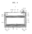
FIG. 4 illustrates a cross-sectional view of a secondary battery according to another embodiment. - Korean Patent Application No.
10-2009-0104309, filed on October 30, 2009 - Example embodiments will now be described more fully hereinafter with reference to the accompanying drawings; however, they may be embodied in different forms and should not be construed as limited to the embodiments set forth herein. Rather, these embodiments are provided so that this disclosure will be thorough and complete, and will fully convey the scope of the invention to those skilled in the art.
- In the drawing figures, the dimensions of layers and regions may be exaggerated for clarity of illustration. It will also be understood that when a layer or element is referred to as being "on" another element, it can be directly on the other element, or intervening elements may also be present. In addition, it will also be understood that when an element is referred to as being "between" two elements, it can be the only element between the two elements, or one or more intervening elements may also be present. Like reference numerals refer to like elements throughout.
-
FIG. 1 illustrates a perspective view of asecondary battery 1 according to an embodiment.FIG. 2 illustrates a cross-sectional view of thesecondary battery 1 taken along a line II-II ofFIG. 1 .FIG. 3 illustrates a partial exploded perspective view of anelectrode assembly 10,current collectors case 34, and an insulating film, sheet, orsheath 200 of thesecondary battery 1 ofFIG. 1 . - Referring to
FIGS. 1 through 3 , thesecondary battery 1 may include theelectrode assembly 10,electrode terminals sheath 200, and thecase 34. Thecase 34 may accommodate theelectrode assembly 10. Theelectrode assembly 10 may be electrically connected to an outside device via theelectrode terminals insulating film 200 may be disposed between theelectrode assembly 10 and thecase 34. Theinsulating film 200 may perform an insulating function between theelectrode assembly 10 and thecase 34 so as to compensate for, i.e., offset or absorb, vibration of theelectrode assembly 10 and theelectrode terminals - The
electrode assembly 10 may include apositive electrode 11, anegative electrode 12, and aseparator 13. Thepositive electrode 11, thenegative electrode 12, and theseparator 13 may be wound such that theseparator 13 is disposed between thepositive electrode 11 and thenegative electrode 12. Thepositive electrode 11 may include a positive electrodeuncoated unit 11a and a positive electrode coatedunit 11a. Thenegative electrode 12 may include a negative electrodeuncoated unit 12a and a negative electrode coatedunit 12b. The positive electrodeuncoated unit 11a and the negative electrodeuncoated unit 12a may include a metal foil current collector on which an active material is not coated. The positive electrode coatedunit 11b and the negative electrode coatedunit 12b may include a metal foil current collector on which an active material is coated. The positive electrodeuncoated unit 11a may be formed at a side of thepositive electrode 11 in a longitudinal direction of thepositive electrode 11. The negative electrodeuncoated unit 12a may be formed at a side of thenegative electrode 12 in a longitudinal direction of thenegative electrode 12. In an implementation, theelectrode assembly 10 may include thepositive electrode 11, thenegative electrode 12, and theseparator 13 wound in a cylindrical shape. Then the woundpositive electrode 11,negative electrode 12, andseparator 13 may be pressed. Theelectrode assembly 10 may be pressed into a plate shape so as to form aflat portion 18 and acurved portion 19, as illustrated inFIG. 3 . Theflat portion 18 may be formed by winding thepositive electrode 11, thenegative electrode 12, and theseparator 13 and then pressing thepositive electrode 11, thenegative electrode 12, and theseparator 13 so as to planarize a portion of a circumference of theelectrode assembly 10. Thecurved portion 19 may be disposed at ends of theflat portion 18, both of which may be formed by pressing theelectrode assembly 10. - A positive electrode
current collector unit 40a may be coupled to the positive electrode uncoatedunit 11a of theelectrode assembly 10 by, e.g., welding. The positive electrodecurrent collector unit 40a may be electrically connected to apositive electrode terminal 21 via alead element 28. Thus, thepositive electrode terminal 21 may be connected to thepositive electrode 11 of theelectrode assembly 10 via thelead element 28 and the positive electrodecurrent collector unit 40a. A negative electrodecurrent collector 40b may be electrically connected to anegative electrode terminal 22 via anotherlead element 28. Thus, thenegative electrode terminal 22 may be connected to thenegative electrode 12 of theelectrode assembly 10 via the otherlead element 28 and the negative electrodecurrent collector 40b. An insulatingelement 26 may be disposed between thelead elements 28 and acap plate 30 in order to insulate these components from each other. Thelead elements 28 may include current collectinglead elements 28b attached to respectivecurrent collectors lead elements 28a attached torespective electrode terminals - The
electrode terminals positive electrode terminal 21 and thenegative electrode terminal 22. Thepositive electrode terminal 21 and thenegative electrode terminal 22 may be electrically connected to thepositive electrode 11 and thenegative electrode 12, respectively, and may protrude outside of thecase 34. - The
cap plate 30 may be coupled to an end of thecase 34. Thecase 34 may have a can shape having an open side. Thus, the open side may be sealed by thecap plate 30. Theelectrode assembly 10 together with electrolyte may be accommodated in thecase 34 through the open side. Thecap plate 30 may cover thecase 34 such that theelectrode terminals case 34 and thecap plate 30 may be welded using, e.g., a laser, so as to seal thecase 34 in which theelectrode assembly 10 together with the electrolyte are accommodated. Thecap plate 30 may have a thin plate shape. Anelectrolyte inlet 38a for injecting the electrolyte may be formed in thecap plate 30. A sealingcap 38 may be inserted into theelectrolyte inlet 38a. Avent element 39 including a groove may be formed in thecap plate 30 so as to be capable of being broken open by a predetermined internal pressure in thecase 34. - The insulating
film 200 will now be described. With reference toFIG. 1 , thecase 34 of thesecondary battery 1 may include first walls X and X', second walls Y and Y', and a third wall Z. The first walls X and X' may be parallel to a breadth direction of thecap plate 30 and may face each other. The second walls Y and Y' are in parallel to a longitudinal direction of thecap plate 30 and may face each other. The third wall Z may face thecap plate 30 so as to constitute a bottom of thecase 34. Thecap plate 30 may be formed on a Z' plane. In this case, when, e.g., a rotational and/or vibrational force, are applied to thesecondary battery 1, it may not be easy to move theelectrode assembly 10 with respect to the second walls Y and Y', i.e., in a direction orthogonal thereto, due to the thickness of theelectrode assembly 10. However, a space may exist between theelectrode assembly 10 and the first walls X and X' or the third wall Z of thecase 34, i.e., in a direction orthogonal thereto. Accordingly, theelectrode assembly 10 may be affected by the vibrational and/or rotational force. That is, theelectrode assembly 10 may move with respect to the first walls X and X' and/or the third wall Z of thecase 34. If thesecondary battery 1 is a medium or large-sized second battery, a relatively large space may exist between theelectrode assembly 10 and thecase 34 such that theelectrode assembly 10 may be seriously affected by the, e.g., vibrational and/or rotational force. - As illustrated in
FIGS. 2 and3 , the insulatingfilm 200 may surround theelectrode assembly 10 and thecurrent collectors electrode assembly 10 and/or thecurrent collectors film 200. The insulatingfilm 200 including the recess may perform an insulating function, and may compensate for, i.e., absorb, vibration of theelectrode assembly 10, thecurrent collectors lead element 28 with respect to thecase 34. In such case, as illustrated inFIG. 3 , the recess may be formed in the insulatingfilm 200 so as to correspond to a shape of thecurrent collectors current collectors case 34, rather than oscillating with respect to thecase 34. Referring toFIG. 3 , a thickness of each portion of the insulatingfilm 200 disposed on the first walls X and X' may be thicker than a thickness of each portion of the insulatingfilm 200 disposed on the second walls Y and Y'. That is, a space between the first walls X and X' may be filled by forming with a thicker thickness each portion of the insulatingfilm 200 disposed on the first walls X and X' than that of each portion of the insulatingfilm 200 disposed on the second walls Y and Y'. Further, thecurrent collectors case 34 may be integrated with each other, i.e., may be fixed relative to one another, by forming the recess in the insulatingfilm 200. - However, the position and shape of the insulating
film 200 are not limited to any particular form or arrangement described above. That is, the thickness of each portion of the insulatingfilm 200 disposed on the first walls X and X' and the third wall Z may be greater than that of each portion of the insulatingfilm 200 disposed on the second walls Y and Y'. In an implementation, a thickness of the insulatingfilm 200 adjacent to the pair of first walls X, X' may be thicker than a thickness of the insulatingfilm 200 adjacent to the pair of second walls Y, Y' . In another implementation, the thickness of the insulatingfilm 200 adjacent to the pair of first walls X, X' and the third wall Z may be thicker than the thickness of the insulatingfilm 200 adjacent the pair of second walls Y, Y'. In yet another implementation, the thickness of the insulatingfilm 200 adjacent to the third wall Z may be thicker than the thickness of the insulatingfilm 200 adjacent to the pair of second walls Y, Y'. Vibration of theelectrode assembly 10 may be prevented by forming a relatively thick portion of the insulatingfilm 200 adjacent to a wall where space exists. - The thickness of the insulating
film 200 may be, e.g., about 50 µm to about 1 mm. The insulatingfilm 200 including the recess may be formed as a straight line shape along a plane of walls of thecase 34. The recess of the insulatingfilm 200 may be formed so as to correspond to a shape of thecurrent collectors electrode assembly 10. Alternatively, the recess of the insulatingfilm 200 may be formed to include, e.g., unevenness, i.e., a protuberance pattern, or an elastic element, rather than corresponding to the shape of thecurrent collectors electrode assembly 10. -
Terminal holes cap plate 30. The terminal holes 21a and 22a may include a positiveelectrode terminal hole 21a and a negativeelectrode terminal hole 22a. Thepositive electrode terminal 21 may protrude through the positiveelectrode terminal hole 21a. Thenegative electrode terminal 22 may protrude through the negativeelectrode terminal hole 22a. Anupper gasket 25 and alower gasket 27 may be disposed between thecap plate 30 and theelectrode terminals cap plate 30 from theelectrode terminals lower gasket 27 may be inserted into therespective terminal holes cap plate 30. Theupper gasket 25 may be installed at an upper portion of thecap plate 30. Awasher 24 for buffering a clamping force may be installed on theupper gasket 25. Screw threads may be formed on thepositive electrode terminal 21 and thenegative electrode terminal 22, respectively, so as to be coupled to anut 29. Thenut 29 may support theelectrode terminals - However, the embodiments are not limited thereto. In an implementation, the
electrode terminals electrode terminals terminal holes upper gasket 25 may be inserted into theterminal holes electrode terminals electrode terminals electrode terminals electrode terminals cap plate 30. - According to the embodiments, the
secondary battery 1 may be a lithium-ion battery, but is not limited thereto. Thesecondary battery 1 may be, e.g., a nickelcadmium secondary battery, a nickel-hydrogen secondary battery, or a lithium battery. - According to the embodiments, the
secondary battery 1 may have a square, i.e., prismatic or hexahedral, shape, as illustrated inFIGS. 1 through 3 , but is not limited thereto. Thesecondary battery 1 may be, e.g., a cylindrical battery or a pouch type battery. - The
positive electrode 11, thecurrent collectors lead element 28 that are electrically connected to each other may be formed of the same material, e.g., aluminum (Al). In this case, a positive electrode short circuiting induction element (not illustrated) may be formed of the same material as that of thelead element 28, e.g., aluminum (Al). Thelead element 28 may be integrally formed with the positive electrode short circuiting induction element or may be connected to the positive electrode short circuiting induction element by, e.g., welding. - The
negative electrode 12, thecurrent collectors lead element 28 that are electrically connected may be formed of the same material, e.g., copper (Cu). In this case, a negative electrode short circuiting induction element (not illustrated) may be formed of the same material as that of thelead element 28, e.g., copper (Cu). Thelead element 28 may be integrally formed with the negative electrode short circuiting induction element or may be connected to the negative electrode short circuiting induction element by, e.g., welding. - An
internal space 14 may be formed in the center of theelectrode assembly 10 by compressing theelectrode assembly 10 into a flat shape while theelectrode assembly 10 is wound. Each of thecurrent collectors support protrusion 42 inserted into theinternal space 14. Thecurrent collectors attachment plate 41 coupled to a lateral end of theelectrode assembly 10 so as to compress the positive electrodeuncoated unit 11a and the negative electrodeuncoated unit 12a and welded thereto. - The
support protrusion 42 may extend from a center of a width direction of the respectivecurrent collector current collector support protrusion 42 may correspond to the height of theinternal space 14 of theelectrode assembly 10. - The
support protrusion 42 may be inserted into theinternal space 14 of theelectrode assembly 10 so as to support theelectrode assembly 10, thereby preventing contact errors between theelectrode assembly 10 and thecurrent collectors support protrusion 42 may support theelectrode assembly 10 in a width direction of theinternal space 14 as well as in a longitudinal direction of theinternal space 14, thereby stably supporting theelectrode assembly 10. - The
attachment plates 41 may be disposed at both lateral ends of thesupport protrusion 42. Theattachment plates 41 may be coupled to lateral end surfaces of theelectrode assembly 10 so as to compress the positive electrodeuncoated unit 11a and the negative electrodeuncoated unit 12a. The lateral end surface is a surface perpendicular to a central axis when theelectrode assembly 10 is wound. - Thus, the
attachment plates 41 may contact the respective positive electrodeuncoated unit 11a and negative electrodeuncoated unit 12a over a relatively large area. Theattachment plate 41 may be attached to the lateral end surface of theelectrode assembly 10 by, e.g., laser welding. When theattachment plate 41 is attached by laser welding, a thickness of each of thecurrent collector units attachment plate 41 is attached by ultrasonic welding, thereby reducing a resistance of each of thecurrent collector units - Since the
current collectors uncoated unit 11a and the negative electrodeuncoated unit 12a, an entire output of theelectrode assembly 10 may be increased by reducing an area of each of the positive electrodeuncoated unit 11a and negative electrodeuncoated unit 12a and increasing an area of each of thecoated units - However, the structure of the
secondary battery 1 is not limited thereto. According to another embodiment, theupper gasket 25, the insulatingelement 26, and thelower gasket 27 for electrically separating thepositive electrode 11 or thenegative electrode 12 from thecap plate 30 may not be installed in one of thepositive electrode terminal 21 or thenegative electrode terminal 22. For example, theupper gasket 25 and thelower gasket 27 may not be installed between thepositive electrode terminal 21 and thecap plate 30; and the insulatingelement 26 may not be installed between thelead element 28 and thecap plate 30 at thepositive electrode terminal 21. In this case, thepositive electrode terminal 21 may pass directly through the positiveelectrode terminal hole 21a so as to contact thecap plate 30 without theupper gasket 25 and thelower gasket 27. In addition, thelead element 28 may contact thecap plate 30 directly. In this case, thecap plate 30 and thecase 34 may have the same polarity as that of thepositive electrode terminal 21. -
FIG. 4 illustrates a cross-sectional view of a secondary battery 1' according to another embodiment. Comparing the secondary battery 1' with thesecondary battery 1 ofFIGS. 1 and2 ,FIG. 4 illustrates a case where theupper gasket 125, the insulatingelement 126, and thelower gasket 127 for electrically separating a positive electrode terminal (not visible) or anegative electrode terminal 122 from acap plate 130 are not installed in a positive electrode terminal hole (not visible) or a negativeelectrode terminal hole 122a. - Like reference numerals in
FIGS. 1 ,2 , and4 denote like elements, and thus their description will be omitted. Thesecondary battery 1 is referred to in order to understand the secondary battery 1'. - Referring to
FIG. 4 , in the secondary battery 1', theupper gasket 125 and thelower gasket 127 may not be installed between the positive electrode terminal and thecap plate 130; and the insulatingelement 26 may not be installed between alead element 128 and thecap plate 130 at the positive electrode terminal. - In this case, the positive electrode terminal may pass directly through a positive electrode terminal hole so as to contact the
cap plate 130 without theupper gasket 125 and thelower gasket 127. In addition, thelead element 128 at the positive electrode terminal may directly contact thecap plate 130. With such an arrangement, thecap plate 130 and acase 134 may have the same polarity as that of the positive electrode terminal. - In an implementation, the insulating
film 200 including a recess may be disposed between theelectrode assembly case FIGS. 1 ,2 ,3 , and4 . That is, theelectrode assembly 10 and thecase 34 may be insulated from each other. As illustrated inFIG. 4 , a negative electrodecurrent collector unit 140b may be electrically connected to thenegative electrode terminal 122 and insulated from thecase 134. A positive electrodecurrent collector unit 140a does not have to be insulated from thecase 134. However, in order to prevent shaking and movement of theelectrode assembly 110 due to vibration of thecase 134, the insulatingfilm 200 including the recess corresponding to a shape of thecurrent collector units electrode assembly 110 may be included to insulate and/or to compensate for the effects of vibration. - The secondary battery of an embodiment may be used in an electric or hybrid electric vehicle, e.g., an electric or hybrid electric car, an electric bicycle, an electric scooter, and the like.
- Exemplary embodiments have been disclosed herein, and although specific terms are employed, they are used and are to be interpreted in a generic and descriptive sense only and not for purpose of limitation.
Claims (9)
- A secondary battery (1, 1'), comprising:an electrode assembly (10, 110), the electrode assembly including a separator (13, 113) between a positive electrode (11, 111) and a negative electrode (12, 112);current collectors (40a, 40b, 140a, 140b), the current collectors being electrically connected to the positive electrode and the negative electrode, respectively;a case (34, 134), the case accommodating the electrode assembly and the current collectors;a cap plate (30, 130), the cap plate coupled to an opening in the case; andan insulating film (200) between the current collectors and the case, the insulating film including a recess corresponding to a shape of at least one of the current collectors and/or the electrode assembly to offset a vibration of the current collectors with respect to the case.
- The secondary battery (1, 1') as claimed in claim 1, wherein the case (34, 134) is a prismatic type and includes:a pair of first walls (X, X'), the pair of first walls being parallel to a breadth direction of the cap plate (30, 130) and facing each other,a pair of second walls (Y, Y'), the pair of second walls being parallel to a length direction of the cap plate, anda third wall (Z), the third wall facing the cap plate and being disposed on a bottom of the case.
- The secondary battery (1, 1') as claimed in claim 2, wherein a thickness of a portion of the insulating film (200) disposed adjacent to the first walls (X, X') is thicker than a thickness of a portion of the insulating film disposed adjacent to the second walls (Y, Y').
- The secondary battery (1, 1') as claimed in claim 2, wherein a thickness of a portion of the insulating film (200) disposed adjacent to the first walls (X, X') and the third wall (Z) is thicker than a thickness of a portion of the insulating film adjacent to the second walls (Y, Y').
- The secondary battery (1, 1') as claimed in one of the preceding claims, further comprising at least one electrode terminal (21, 22, 121) electrically connected to at least one of the current collectors (40a, 40b, 140a, 140b) and protruding through the cap plate (30, 130).
- The secondary battery (1, 1') as claimed in one of the preceding claims , wherein the insulating film (200) insulates the electrode assembly (10, 110) from the case (34, 134).
- The secondary battery (1, 1') as claimed in one of the preceding claims , wherein a thickness of the insulating film (200) is about 50 µm to about 1 mm.
- The secondary battery (1, 1') as claimed in one of the preceding claims , wherein the secondary battery is a lithium secondary battery.
- An electric vehicle or hybrid electric vehicle including the secondary battery (1, 1') as claimed in one of the preceding claims.
Applications Claiming Priority (1)
| Application Number | Priority Date | Filing Date | Title |
|---|---|---|---|
| KR1020090104309A KR101097221B1 (en) | 2009-10-30 | 2009-10-30 | Secondary Battery |
Publications (2)
| Publication Number | Publication Date |
|---|---|
| EP2317588A1 true EP2317588A1 (en) | 2011-05-04 |
| EP2317588B1 EP2317588B1 (en) | 2013-12-25 |
Family
ID=43259862
Family Applications (1)
| Application Number | Title | Priority Date | Filing Date |
|---|---|---|---|
| EP10188184.5A Active EP2317588B1 (en) | 2009-10-30 | 2010-10-20 | Secondary battery |
Country Status (3)
| Country | Link |
|---|---|
| US (1) | US8455134B2 (en) |
| EP (1) | EP2317588B1 (en) |
| KR (1) | KR101097221B1 (en) |
Cited By (7)
| Publication number | Priority date | Publication date | Assignee | Title |
|---|---|---|---|---|
| EP2541647A3 (en) * | 2011-07-01 | 2015-07-29 | GS Yuasa International Ltd. | Electric storage device and spacer |
| US9472802B2 (en) | 2011-07-25 | 2016-10-18 | Samsung Sdi Co., Ltd. | Secondary battery |
| DE102015209069A1 (en) * | 2015-05-18 | 2016-11-24 | Robert Bosch Gmbh | Battery cell and method of manufacturing a battery cell |
| CN108028326A (en) * | 2015-09-18 | 2018-05-11 | 锂能源和电力有限责任两合公司 | Battery |
| CN112331973A (en) * | 2020-04-17 | 2021-02-05 | 宁德时代新能源科技股份有限公司 | End cover assembly, battery monomer, battery module and device |
| US11715867B2 (en) | 2020-04-17 | 2023-08-01 | Contemporary Amperex Technology Co., Limited | End cover assembly, battery cell, battery module and device |
| WO2024033500A1 (en) * | 2022-08-12 | 2024-02-15 | Northvolt Ab | Battery cell with insulating element |
Families Citing this family (12)
| Publication number | Priority date | Publication date | Assignee | Title |
|---|---|---|---|---|
| KR101243398B1 (en) * | 2011-02-10 | 2013-03-13 | 로베르트 보쉬 게엠베하 | Rechargeable battery |
| US9299972B2 (en) * | 2011-09-28 | 2016-03-29 | Samsung Sdi Co., Ltd | Rechargeable battery with separating member between current collector and battery case |
| CN110224087A (en) * | 2011-11-03 | 2019-09-10 | Cps科技控股有限公司 | Prismatic lithium ion battery cell with positive polarity rigid container |
| KR101695992B1 (en) * | 2011-11-30 | 2017-01-13 | 삼성에스디아이 주식회사 | Secondary battery |
| DE102012217605A1 (en) * | 2012-09-27 | 2014-03-27 | Robert Bosch Gmbh | System comprising at least one holder for a collector of an electrode assembly and method for producing such a system |
| JP6187148B2 (en) * | 2013-10-24 | 2017-08-30 | 株式会社Gsユアサ | Storage element and power supply module |
| JP6519161B2 (en) * | 2014-01-17 | 2019-05-29 | 株式会社Gsユアサ | Storage element |
| DE102014201160A1 (en) * | 2014-01-23 | 2015-07-23 | Robert Bosch Gmbh | Battery cell with at least one electrode ensemble |
| JP2015185470A (en) * | 2014-03-25 | 2015-10-22 | 株式会社Gsユアサ | Power storage element |
| JP6972583B2 (en) * | 2017-03-07 | 2021-11-24 | 株式会社Gsユアサ | Power storage element |
| JP6645533B2 (en) * | 2018-04-12 | 2020-02-14 | 株式会社Gsユアサ | Storage element |
| DE102022204775A1 (en) | 2022-05-16 | 2023-11-16 | Robert Bosch Gesellschaft mit beschränkter Haftung | Method for monitoring a battery |
Citations (4)
| Publication number | Priority date | Publication date | Assignee | Title |
|---|---|---|---|---|
| GB236316A (en) * | 1924-04-17 | 1925-07-09 | Henry Samuel Potter | Improvements in or relating to electric accumulators |
| US20010008725A1 (en) * | 1993-11-19 | 2001-07-19 | William G. Howard | Current collector for lithium electrode |
| EP1482577A1 (en) * | 2002-02-13 | 2004-12-01 | Matsushita Electric Industrial Co., Ltd. | Method of manufacturing battery pack |
| DE102008008004A1 (en) * | 2008-02-07 | 2009-01-29 | Daimler Ag | Filling body, for spaces in a motor vehicle battery, has a flexible sealed shell to contain a gas or fluid |
Family Cites Families (6)
| Publication number | Priority date | Publication date | Assignee | Title |
|---|---|---|---|---|
| US6083640A (en) | 1998-09-22 | 2000-07-04 | Samsung Display Device Co., Ltd. | Secondary battery with electrode assembly fixing device |
| KR100303828B1 (en) | 1998-09-22 | 2001-10-19 | 김순택 | Secondary battery |
| JP2004303500A (en) * | 2003-03-31 | 2004-10-28 | Sanyo Electric Co Ltd | Square battery |
| KR100599709B1 (en) * | 2004-07-28 | 2006-07-12 | 삼성에스디아이 주식회사 | Secondary battery |
| JP4806270B2 (en) * | 2006-02-21 | 2011-11-02 | 三洋電機株式会社 | Square battery |
| KR100882915B1 (en) | 2007-07-03 | 2009-02-10 | 삼성에스디아이 주식회사 | Secondary Battery |
-
2009
- 2009-10-30 KR KR1020090104309A patent/KR101097221B1/en active IP Right Grant
-
2010
- 2010-06-22 US US12/801,713 patent/US8455134B2/en active Active
- 2010-10-20 EP EP10188184.5A patent/EP2317588B1/en active Active
Patent Citations (4)
| Publication number | Priority date | Publication date | Assignee | Title |
|---|---|---|---|---|
| GB236316A (en) * | 1924-04-17 | 1925-07-09 | Henry Samuel Potter | Improvements in or relating to electric accumulators |
| US20010008725A1 (en) * | 1993-11-19 | 2001-07-19 | William G. Howard | Current collector for lithium electrode |
| EP1482577A1 (en) * | 2002-02-13 | 2004-12-01 | Matsushita Electric Industrial Co., Ltd. | Method of manufacturing battery pack |
| DE102008008004A1 (en) * | 2008-02-07 | 2009-01-29 | Daimler Ag | Filling body, for spaces in a motor vehicle battery, has a flexible sealed shell to contain a gas or fluid |
Cited By (9)
| Publication number | Priority date | Publication date | Assignee | Title |
|---|---|---|---|---|
| EP2541647A3 (en) * | 2011-07-01 | 2015-07-29 | GS Yuasa International Ltd. | Electric storage device and spacer |
| US10971713B2 (en) | 2011-07-01 | 2021-04-06 | Gs Yuasa International Ltd. | Electric storage device and spacer |
| US9472802B2 (en) | 2011-07-25 | 2016-10-18 | Samsung Sdi Co., Ltd. | Secondary battery |
| EP2551940B1 (en) * | 2011-07-25 | 2018-02-14 | Samsung SDI Co., Ltd. | Secondary battery |
| DE102015209069A1 (en) * | 2015-05-18 | 2016-11-24 | Robert Bosch Gmbh | Battery cell and method of manufacturing a battery cell |
| CN108028326A (en) * | 2015-09-18 | 2018-05-11 | 锂能源和电力有限责任两合公司 | Battery |
| CN112331973A (en) * | 2020-04-17 | 2021-02-05 | 宁德时代新能源科技股份有限公司 | End cover assembly, battery monomer, battery module and device |
| US11715867B2 (en) | 2020-04-17 | 2023-08-01 | Contemporary Amperex Technology Co., Limited | End cover assembly, battery cell, battery module and device |
| WO2024033500A1 (en) * | 2022-08-12 | 2024-02-15 | Northvolt Ab | Battery cell with insulating element |
Also Published As
| Publication number | Publication date |
|---|---|
| US20110104559A1 (en) | 2011-05-05 |
| EP2317588B1 (en) | 2013-12-25 |
| KR20110047612A (en) | 2011-05-09 |
| US8455134B2 (en) | 2013-06-04 |
| KR101097221B1 (en) | 2011-12-21 |
Similar Documents
| Publication | Publication Date | Title |
|---|---|---|
| EP2317588B1 (en) | Secondary battery | |
| US8450008B2 (en) | Secondary battery | |
| EP2490283B1 (en) | Rechargeable battery | |
| EP2244328B1 (en) | Rechargeable battery having a current collecting plate | |
| US8557430B2 (en) | Rechargeable battery having current collector plate with protrusion | |
| US9012065B2 (en) | Secondary battery and battery pack having the same | |
| US9028993B2 (en) | Secondary battery | |
| JP2006040899A (en) | Secondary battery | |
| US9136523B2 (en) | Rechargeable battery | |
| US8927126B2 (en) | Protection circuit assembly and battery pack having the same | |
| KR20180126534A (en) | Multi-joint battery module | |
| KR101726891B1 (en) | Secondary Battery Including Damping Member | |
| EP2429012A1 (en) | Secondary battery | |
| KR101669123B1 (en) | Pouch type secondary battery and battery module including the same | |
| KR101846486B1 (en) | Battery Cell Comprising Unified Cathode Lead and Anode Lead | |
| KR100649568B1 (en) | Secondary battery | |
| CN112652777B (en) | Secondary battery | |
| WO2023171117A1 (en) | Power storage device | |
| JP2023084025A (en) | secondary battery | |
| JP2021132017A (en) | Power storage device | |
| JP2021132014A (en) | Power storage device | |
| JP2023044777A (en) | battery |
Legal Events
| Date | Code | Title | Description |
|---|---|---|---|
| PUAI | Public reference made under article 153(3) epc to a published international application that has entered the european phase |
Free format text: ORIGINAL CODE: 0009012 |
|
| 17P | Request for examination filed |
Effective date: 20101020 |
|
| AK | Designated contracting states |
Kind code of ref document: A1 Designated state(s): AL AT BE BG CH CY CZ DE DK EE ES FI FR GB GR HR HU IE IS IT LI LT LU LV MC MK MT NL NO PL PT RO RS SE SI SK SM TR |
|
| AX | Request for extension of the european patent |
Extension state: BA ME |
|
| 17Q | First examination report despatched |
Effective date: 20120228 |
|
| RAP1 | Party data changed (applicant data changed or rights of an application transferred) |
Owner name: ROBERT BOSCH GMBH Owner name: SAMSUNG SDI CO., LTD. |
|
| GRAP | Despatch of communication of intention to grant a patent |
Free format text: ORIGINAL CODE: EPIDOSNIGR1 |
|
| RIC1 | Information provided on ipc code assigned before grant |
Ipc: H01M 2/18 20060101AFI20130717BHEP Ipc: H01M 2/26 20060101ALI20130717BHEP Ipc: H01M 10/052 20100101ALI20130717BHEP Ipc: H01M 2/02 20060101ALI20130717BHEP Ipc: H01M 10/0587 20100101ALI20130717BHEP |
|
| INTG | Intention to grant announced |
Effective date: 20130802 |
|
| GRAS | Grant fee paid |
Free format text: ORIGINAL CODE: EPIDOSNIGR3 |
|
| GRAA | (expected) grant |
Free format text: ORIGINAL CODE: 0009210 |
|
| AK | Designated contracting states |
Kind code of ref document: B1 Designated state(s): AL AT BE BG CH CY CZ DE DK EE ES FI FR GB GR HR HU IE IS IT LI LT LU LV MC MK MT NL NO PL PT RO RS SE SI SK SM TR |
|
| REG | Reference to a national code |
Ref country code: GB Ref legal event code: FG4D |
|
| REG | Reference to a national code |
Ref country code: CH Ref legal event code: EP |
|
| REG | Reference to a national code |
Ref country code: AT Ref legal event code: REF Ref document number: 647007 Country of ref document: AT Kind code of ref document: T Effective date: 20140115 |
|
| REG | Reference to a national code |
Ref country code: IE Ref legal event code: FG4D |
|
| REG | Reference to a national code |
Ref country code: DE Ref legal event code: R096 Ref document number: 602010012626 Country of ref document: DE Effective date: 20140213 |
|
| PG25 | Lapsed in a contracting state [announced via postgrant information from national office to epo] |
Ref country code: LT Free format text: LAPSE BECAUSE OF FAILURE TO SUBMIT A TRANSLATION OF THE DESCRIPTION OR TO PAY THE FEE WITHIN THE PRESCRIBED TIME-LIMIT Effective date: 20131225 Ref country code: SE Free format text: LAPSE BECAUSE OF FAILURE TO SUBMIT A TRANSLATION OF THE DESCRIPTION OR TO PAY THE FEE WITHIN THE PRESCRIBED TIME-LIMIT Effective date: 20131225 Ref country code: NO Free format text: LAPSE BECAUSE OF FAILURE TO SUBMIT A TRANSLATION OF THE DESCRIPTION OR TO PAY THE FEE WITHIN THE PRESCRIBED TIME-LIMIT Effective date: 20140325 Ref country code: FI Free format text: LAPSE BECAUSE OF FAILURE TO SUBMIT A TRANSLATION OF THE DESCRIPTION OR TO PAY THE FEE WITHIN THE PRESCRIBED TIME-LIMIT Effective date: 20131225 Ref country code: HR Free format text: LAPSE BECAUSE OF FAILURE TO SUBMIT A TRANSLATION OF THE DESCRIPTION OR TO PAY THE FEE WITHIN THE PRESCRIBED TIME-LIMIT Effective date: 20131225 |
|
| REG | Reference to a national code |
Ref country code: NL Ref legal event code: VDEP Effective date: 20131225 |
|
| REG | Reference to a national code |
Ref country code: AT Ref legal event code: MK05 Ref document number: 647007 Country of ref document: AT Kind code of ref document: T Effective date: 20131225 |
|
| REG | Reference to a national code |
Ref country code: LT Ref legal event code: MG4D |
|
| PG25 | Lapsed in a contracting state [announced via postgrant information from national office to epo] |
Ref country code: RS Free format text: LAPSE BECAUSE OF FAILURE TO SUBMIT A TRANSLATION OF THE DESCRIPTION OR TO PAY THE FEE WITHIN THE PRESCRIBED TIME-LIMIT Effective date: 20131225 Ref country code: LV Free format text: LAPSE BECAUSE OF FAILURE TO SUBMIT A TRANSLATION OF THE DESCRIPTION OR TO PAY THE FEE WITHIN THE PRESCRIBED TIME-LIMIT Effective date: 20131225 |
|
| PG25 | Lapsed in a contracting state [announced via postgrant information from national office to epo] |
Ref country code: IS Free format text: LAPSE BECAUSE OF FAILURE TO SUBMIT A TRANSLATION OF THE DESCRIPTION OR TO PAY THE FEE WITHIN THE PRESCRIBED TIME-LIMIT Effective date: 20140425 Ref country code: EE Free format text: LAPSE BECAUSE OF FAILURE TO SUBMIT A TRANSLATION OF THE DESCRIPTION OR TO PAY THE FEE WITHIN THE PRESCRIBED TIME-LIMIT Effective date: 20131225 Ref country code: BE Free format text: LAPSE BECAUSE OF FAILURE TO SUBMIT A TRANSLATION OF THE DESCRIPTION OR TO PAY THE FEE WITHIN THE PRESCRIBED TIME-LIMIT Effective date: 20131225 |
|
| PG25 | Lapsed in a contracting state [announced via postgrant information from national office to epo] |
Ref country code: CY Free format text: LAPSE BECAUSE OF FAILURE TO SUBMIT A TRANSLATION OF THE DESCRIPTION OR TO PAY THE FEE WITHIN THE PRESCRIBED TIME-LIMIT Effective date: 20131225 Ref country code: RO Free format text: LAPSE BECAUSE OF FAILURE TO SUBMIT A TRANSLATION OF THE DESCRIPTION OR TO PAY THE FEE WITHIN THE PRESCRIBED TIME-LIMIT Effective date: 20131225 Ref country code: SK Free format text: LAPSE BECAUSE OF FAILURE TO SUBMIT A TRANSLATION OF THE DESCRIPTION OR TO PAY THE FEE WITHIN THE PRESCRIBED TIME-LIMIT Effective date: 20131225 Ref country code: PT Free format text: LAPSE BECAUSE OF FAILURE TO SUBMIT A TRANSLATION OF THE DESCRIPTION OR TO PAY THE FEE WITHIN THE PRESCRIBED TIME-LIMIT Effective date: 20140428 Ref country code: CZ Free format text: LAPSE BECAUSE OF FAILURE TO SUBMIT A TRANSLATION OF THE DESCRIPTION OR TO PAY THE FEE WITHIN THE PRESCRIBED TIME-LIMIT Effective date: 20131225 Ref country code: AT Free format text: LAPSE BECAUSE OF FAILURE TO SUBMIT A TRANSLATION OF THE DESCRIPTION OR TO PAY THE FEE WITHIN THE PRESCRIBED TIME-LIMIT Effective date: 20131225 Ref country code: NL Free format text: LAPSE BECAUSE OF FAILURE TO SUBMIT A TRANSLATION OF THE DESCRIPTION OR TO PAY THE FEE WITHIN THE PRESCRIBED TIME-LIMIT Effective date: 20131225 Ref country code: ES Free format text: LAPSE BECAUSE OF FAILURE TO SUBMIT A TRANSLATION OF THE DESCRIPTION OR TO PAY THE FEE WITHIN THE PRESCRIBED TIME-LIMIT Effective date: 20131225 |
|
| REG | Reference to a national code |
Ref country code: DE Ref legal event code: R097 Ref document number: 602010012626 Country of ref document: DE |
|
| PG25 | Lapsed in a contracting state [announced via postgrant information from national office to epo] |
Ref country code: DK Free format text: LAPSE BECAUSE OF FAILURE TO SUBMIT A TRANSLATION OF THE DESCRIPTION OR TO PAY THE FEE WITHIN THE PRESCRIBED TIME-LIMIT Effective date: 20131225 |
|
| PLBE | No opposition filed within time limit |
Free format text: ORIGINAL CODE: 0009261 |
|
| STAA | Information on the status of an ep patent application or granted ep patent |
Free format text: STATUS: NO OPPOSITION FILED WITHIN TIME LIMIT |
|
| PG25 | Lapsed in a contracting state [announced via postgrant information from national office to epo] |
Ref country code: PL Free format text: LAPSE BECAUSE OF FAILURE TO SUBMIT A TRANSLATION OF THE DESCRIPTION OR TO PAY THE FEE WITHIN THE PRESCRIBED TIME-LIMIT Effective date: 20131225 |
|
| 26N | No opposition filed |
Effective date: 20140926 |
|
| REG | Reference to a national code |
Ref country code: DE Ref legal event code: R097 Ref document number: 602010012626 Country of ref document: DE Effective date: 20140926 |
|
| PG25 | Lapsed in a contracting state [announced via postgrant information from national office to epo] |
Ref country code: SI Free format text: LAPSE BECAUSE OF FAILURE TO SUBMIT A TRANSLATION OF THE DESCRIPTION OR TO PAY THE FEE WITHIN THE PRESCRIBED TIME-LIMIT Effective date: 20131225 Ref country code: LU Free format text: LAPSE BECAUSE OF FAILURE TO SUBMIT A TRANSLATION OF THE DESCRIPTION OR TO PAY THE FEE WITHIN THE PRESCRIBED TIME-LIMIT Effective date: 20141020 Ref country code: MC Free format text: LAPSE BECAUSE OF FAILURE TO SUBMIT A TRANSLATION OF THE DESCRIPTION OR TO PAY THE FEE WITHIN THE PRESCRIBED TIME-LIMIT Effective date: 20131225 |
|
| REG | Reference to a national code |
Ref country code: CH Ref legal event code: PL |
|
| REG | Reference to a national code |
Ref country code: IE Ref legal event code: MM4A |
|
| PG25 | Lapsed in a contracting state [announced via postgrant information from national office to epo] |
Ref country code: CH Free format text: LAPSE BECAUSE OF NON-PAYMENT OF DUE FEES Effective date: 20141031 Ref country code: LI Free format text: LAPSE BECAUSE OF NON-PAYMENT OF DUE FEES Effective date: 20141031 |
|
| PG25 | Lapsed in a contracting state [announced via postgrant information from national office to epo] |
Ref country code: IE Free format text: LAPSE BECAUSE OF NON-PAYMENT OF DUE FEES Effective date: 20141020 |
|
| PG25 | Lapsed in a contracting state [announced via postgrant information from national office to epo] |
Ref country code: SM Free format text: LAPSE BECAUSE OF FAILURE TO SUBMIT A TRANSLATION OF THE DESCRIPTION OR TO PAY THE FEE WITHIN THE PRESCRIBED TIME-LIMIT Effective date: 20131225 |
|
| PG25 | Lapsed in a contracting state [announced via postgrant information from national office to epo] |
Ref country code: BG Free format text: LAPSE BECAUSE OF FAILURE TO SUBMIT A TRANSLATION OF THE DESCRIPTION OR TO PAY THE FEE WITHIN THE PRESCRIBED TIME-LIMIT Effective date: 20131225 Ref country code: IT Free format text: LAPSE BECAUSE OF FAILURE TO SUBMIT A TRANSLATION OF THE DESCRIPTION OR TO PAY THE FEE WITHIN THE PRESCRIBED TIME-LIMIT Effective date: 20131225 Ref country code: GR Free format text: LAPSE BECAUSE OF FAILURE TO SUBMIT A TRANSLATION OF THE DESCRIPTION OR TO PAY THE FEE WITHIN THE PRESCRIBED TIME-LIMIT Effective date: 20140326 |
|
| PG25 | Lapsed in a contracting state [announced via postgrant information from national office to epo] |
Ref country code: HU Free format text: LAPSE BECAUSE OF FAILURE TO SUBMIT A TRANSLATION OF THE DESCRIPTION OR TO PAY THE FEE WITHIN THE PRESCRIBED TIME-LIMIT; INVALID AB INITIO Effective date: 20101020 Ref country code: TR Free format text: LAPSE BECAUSE OF FAILURE TO SUBMIT A TRANSLATION OF THE DESCRIPTION OR TO PAY THE FEE WITHIN THE PRESCRIBED TIME-LIMIT Effective date: 20131225 Ref country code: MT Free format text: LAPSE BECAUSE OF FAILURE TO SUBMIT A TRANSLATION OF THE DESCRIPTION OR TO PAY THE FEE WITHIN THE PRESCRIBED TIME-LIMIT Effective date: 20131225 |
|
| REG | Reference to a national code |
Ref country code: FR Ref legal event code: PLFP Year of fee payment: 7 |
|
| REG | Reference to a national code |
Ref country code: FR Ref legal event code: PLFP Year of fee payment: 8 |
|
| PG25 | Lapsed in a contracting state [announced via postgrant information from national office to epo] |
Ref country code: MK Free format text: LAPSE BECAUSE OF FAILURE TO SUBMIT A TRANSLATION OF THE DESCRIPTION OR TO PAY THE FEE WITHIN THE PRESCRIBED TIME-LIMIT Effective date: 20131225 |
|
| REG | Reference to a national code |
Ref country code: FR Ref legal event code: PLFP Year of fee payment: 9 |
|
| PG25 | Lapsed in a contracting state [announced via postgrant information from national office to epo] |
Ref country code: AL Free format text: LAPSE BECAUSE OF FAILURE TO SUBMIT A TRANSLATION OF THE DESCRIPTION OR TO PAY THE FEE WITHIN THE PRESCRIBED TIME-LIMIT Effective date: 20131225 |
|
| REG | Reference to a national code |
Ref country code: DE Ref legal event code: R079 Ref document number: 602010012626 Country of ref document: DE Free format text: PREVIOUS MAIN CLASS: H01M0002180000 Ipc: H01M0050463000 |
|
| P01 | Opt-out of the competence of the unified patent court (upc) registered |
Effective date: 20230530 |
|
| PGFP | Annual fee paid to national office [announced via postgrant information from national office to epo] |
Ref country code: FR Payment date: 20230929 Year of fee payment: 14 |
|
| PGFP | Annual fee paid to national office [announced via postgrant information from national office to epo] |
Ref country code: GB Payment date: 20231006 Year of fee payment: 14 |
|
| PGFP | Annual fee paid to national office [announced via postgrant information from national office to epo] |
Ref country code: DE Payment date: 20230929 Year of fee payment: 14 |