EP2324741A1 - Tablet transport vehicle - Google Patents
Tablet transport vehicle Download PDFInfo
- Publication number
- EP2324741A1 EP2324741A1 EP10188579A EP10188579A EP2324741A1 EP 2324741 A1 EP2324741 A1 EP 2324741A1 EP 10188579 A EP10188579 A EP 10188579A EP 10188579 A EP10188579 A EP 10188579A EP 2324741 A1 EP2324741 A1 EP 2324741A1
- Authority
- EP
- European Patent Office
- Prior art keywords
- wall
- space
- partitions
- tray
- trolley according
- Prior art date
- Legal status (The legal status is an assumption and is not a legal conclusion. Google has not performed a legal analysis and makes no representation as to the accuracy of the status listed.)
- Granted
Links
- 235000013305 food Nutrition 0.000 claims abstract description 42
- 238000005192 partition Methods 0.000 claims description 40
- 239000007787 solid Substances 0.000 claims description 5
- 230000005496 eutectics Effects 0.000 claims description 4
- 238000000926 separation method Methods 0.000 abstract description 2
- 238000001816 cooling Methods 0.000 description 5
- 235000021186 dishes Nutrition 0.000 description 3
- 239000002184 metal Substances 0.000 description 3
- 238000003780 insertion Methods 0.000 description 2
- 230000037431 insertion Effects 0.000 description 2
- 230000000284 resting effect Effects 0.000 description 2
- 238000004140 cleaning Methods 0.000 description 1
- 235000021270 cold food Nutrition 0.000 description 1
- 238000010276 construction Methods 0.000 description 1
- 230000003670 easy-to-clean Effects 0.000 description 1
- 235000021268 hot food Nutrition 0.000 description 1
- 238000009434 installation Methods 0.000 description 1
- 239000011810 insulating material Substances 0.000 description 1
- 238000009413 insulation Methods 0.000 description 1
- 235000012054 meals Nutrition 0.000 description 1
- 230000002093 peripheral effect Effects 0.000 description 1
- 235000012046 side dish Nutrition 0.000 description 1
- 238000005496 tempering Methods 0.000 description 1
Images


Classifications
-
- A—HUMAN NECESSITIES
- A47—FURNITURE; DOMESTIC ARTICLES OR APPLIANCES; COFFEE MILLS; SPICE MILLS; SUCTION CLEANERS IN GENERAL
- A47J—KITCHEN EQUIPMENT; COFFEE MILLS; SPICE MILLS; APPARATUS FOR MAKING BEVERAGES
- A47J39/00—Heat-insulated warming chambers; Cupboards with heating arrangements for warming kitchen utensils
- A47J39/006—Heat-insulated warming chambers; Cupboards with heating arrangements for warming kitchen utensils for either storing and preparing or for preparing food on serving trays, e.g. heating, thawing, preserving
Definitions
- the invention relates to a tray dolly having a limited from a front, a back and side walls interior, with two partitions, which extend from the front to the back and have a plurality of vertically spaced receiving slots for insertion of food trays, and with doors for opening and closing of the interior.
- the interior is divided by the partitions into three thermally separated spaces and receives four stacks of food trays, each resting on support elements on a side wall and projecting into the limited by the two partitions middle space.
- two food trays next to each other and in the receiving slots each two food trays can be arranged one behind the other on the front and the back.
- Such a tray dolly is for food distribution z. B. used in the hospital sector.
- a lunch menu of the dining trays regularly includes a hot dish prepared on a plate and spatially separated side dishes for chilled or chilled food. Accordingly, the interior of the tray trolley is divided by partitions into thermally separated rooms that form a hot zone for the hot food and a cold zone for the shells or food to be kept cool.
- a tray dolly with the features described above is made US 5 159 973 A known.
- the known trolley has a closed rear wall and on its front a double-leaf door. The interior is divided by partitions into three thermally separated rooms, the middle room designed as a cooling zone and interchangeable eutectic cold plates is populated.
- the cold plates are drawer-like housed in a frame having outside guide rails for a peripheral support of the food trays.
- the food trays are at one end on the guide rails of the centrally arranged frame and are supported at its other end to support elements which are arranged on the side walls of the trolley.
- the partitions, which thermally separate hot zones from the cooling zone are not load-bearing elements and have no control and support function for the food trays.
- the rack disposed in the cooling zone must be solid and, as a result, occupy a substantial portion of the interior of the tray transport cart.
- the frame is difficult to clean.
- Particularly unsatisfactory is the accessibility to the food trays, which can be removed only on the front side of the trolley.
- Unsatisfactory is also the accessibility to the food trays, which can be removed only at the front of the trolley.
- the trolley With regard to the placement of the trolley is disadvantageous that the accessible on the same page dining trays are not aligned the same and consequently a part of the food trays must be rotated by 180 ° when inserted into the trolley.
- the food trays are provided with address cards, which contain, for example, the name of the recipient as well as information about the tray equipment. When turning the food trays, these cards have to be repositioned, which is complicated and in practice not very practical.
- a tray dolly for receiving two tray trays is known, with one tray accessible from the outside by a front door and the other stack by a rear door.
- the interior of the tray dolly is through partitions in three subdivided thermally separated spaces, wherein the middle space forms a hot zone for both food tray stack and the two outer spaces are accessible only on one side from the outside and form a cooling zone for each stack of food trays.
- Special trays must be used with a space between two hot and chilled food zones. The two zones are held together by a rear connecting bar. If the trays are inserted into the trolley, one of the thermal partitions engages in the intermediate space and separates the two zones.
- the trays are elaborate custom-made products. Also the space utilization of the
- the present invention seeks to provide a tray dolly that allows easy access to trays arranged therein, is characterized by a particularly space-saving design and the interior can be cleaned well.
- the object is achieved in that one of the two limited by a side wall and a partition outside spaces is closed at the front by a solid front wall, that the other also from a side wall and a partition limited exterior space at the back has a fixed rear wall and that at the front and the back of each other diagonally offset doors are arranged, each of which closes the middle room and one of the two outdoor spaces.
- the food trays can be removed from two sides of the tray transport cart and inserted.
- the dining trays to be inserted on one side always have the same orientation, which facilitates handling when inserting the dining trays into the tray dolly simplified.
- the arrangement according to the invention makes it possible for several persons to work on the transport carriage without hindering each other.
- the partitions are expediently designed as load-bearing elements and form in conjunction with the adjacent front or rear wall and the side wall connected thereto a dimensionally stable arrangement.
- the partition walls for the thermal separation of the areas are designed as load-bearing elements comb-like and have a rear web, which is connected to the adjacent front wall or rear wall.
- the dividing walls are configured as load-bearing elements in such a way that, in combination with the adjoining front wall or rear wall and the side wall connected thereto, they can receive the weight of two stacks of ten trays each equipped with crockery components.
- the food trays are supported and guided on the support elements of a side wall as well as in the receiving slots of a dividing wall and protrude into the middle space with a projecting end.
- the middle space which is thermally separated from the two outer spaces, in this preferred embodiment of the invention does not include a support structure for the food trays and therefore is easy to clean.
- the middle space may have a chamber width that is not or not significantly different from the width of the adjoining exterior spaces. This also contributes to the fact that the thermally separated rooms of the interior can be cleaned well and easily.
- each of a side wall and a partition wall, both outer spaces have the same width and the space bounded by the partition walls has a chamber width that is 0.8 times to 1.2 times the width of an outer space.
- the side walls, the front wall and the rear wall are preferably made of dimensionally stable thermally insulated panels, for example foamed sheet metal panels or sheet metal panels, which contain an insert of an insulating material.
- thermal insulation and the door leaves of the doors are advantageously made of thermally insulated panels.
- the thermal partitions, which also form load-bearing parts, are preferably made of plastic plates or high-strength sandwich panels.
- a holder for accommodating at least one eutectic cold storage plate can be arranged.
- the doors of the tray transport carriage are preferably designed as swing doors and have a door leaf, which is pivotable about an axis adjacent to the side wall and abuts in the open position on the outside of the side wall of the trolley.
- the width of the door is slightly smaller than the width of the side wall.
- the trolley rods are conveniently arranged for gripping, extending vertically from the bottom of the trolley to an upper cover.
- the door wings are suitably hinged to two of the rods.
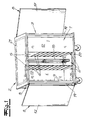
- the tray transport trolley shown in the figures is used for food distribution z. In the hospital sector. In its basic construction, it comprises an interior space 4 bounded by a front side 1, a rear side 2 and side walls 3, two partitions 5 which extend from the front side to the rear side and have a plurality of vertically spaced receiving slots 6 for inserting food trays 7, and doors 8 for opening and closing the interior.
- the interior 4 is divided by the partitions 5 into three thermally separated spaces V1, V2, V3 and receives four stacks of food trays, each resting on supporting elements 9 on a side wall 3 and projecting into the bounded by the two partitions 5 middle space V2 ,
- the stacks each comprise, for example, ten food trays 7, which are equipped with hot dishes arranged on plates 10 and spatially separated therefrom with shells 11 for cold meals or foods to be kept cool.
- the representation in Fig. 2 takes one that two dining trays S next to each other and in the receiving slots in each case two food trays S can be arranged one behind the other at the front 1 and on the back 2.
- the arrangement of the partitions 5 and the configuration of the food trays 7 is coordinated so that the shells 11 are housed for cold food or cool food in the limited space of two partitions 5 middle space V2 and the dishes arranged on dishes 10 warm the two outdoor spaces V1, V3 are assigned.
- the limited by the partitions 5 middle space V2 forms insofar a cooling zone, while each of a side wall 3 and a partition wall 5 bounded external spaces V1, V3 represent hot zones in which a higher temperature is established than in the middle space V2.
- FIG. 2 It can be seen that one of the two exterior spaces V1, V3 on the front side 1 is closed by a solid front wall and that the other exterior space on the rear side 2 has a fixed rear wall 13. At the front 1 and at the back 2 each have a door 8 is arranged, wherein the doors 8 are mutually offset diagonally and respectively close the middle space V2 and one of the two exterior spaces V1 or V3.
- the partitions 5 are formed like a supporting elements comb-like and have a rear web 14 which is connected to the adjacent front wall or rear wall 13.
- the partitions 5 form in conjunction with the adjacent front wall 13 and rear wall 13 and the adjoining side wall 3 dimensionally stable supporting structures, which receive the weight of two stacks S from each more dining trays 7 and arranged thereon crockery components.
- the food trays 7 are supported and guided in the embodiment of the one side wall 3 associated support elements 9 and in the receiving slots 6 of a partition wall 5 and project with a projecting end into the middle space V2.
- the middle space V2 is fundamentally executable without installation and does not have to contain a support structure for supporting the food trays 7.
- a support of the middle space V2 projecting end of the food trays 7, z. B. in the form of a punctiform edition, but is also possible and should be encompassed by the invention.
- Each bounded by a side wall 3 and a partition wall 5 two outer spaces V1, V3 have the same width.
- the central space bounded by the partitions expediently has a chamber width which is 0.8 times to 1.2 times the width of an outside space. Due to the large chamber width, which differs only slightly from the width of the two outer spaces V1, V3, the middle space V2 can be cleaned well.
- the side walls 3, the front wall 12, the rear wall 13 and preferably also the door leaves of the doors 8 are preferably made of thermally insulated panels, for example, foamed or provided with an insulating insert sheet metal panels.
- the partitions can be made of solid plastic plates, z. B. from the plastic POM, be made.
- a holder 15 for receiving at least one eutectic cold storage plate 16 is disposed in the space bounded by the partition walls 5 V2.
- the holder 15 and the cold storage plates 16 inserted therein can be used as a lateral stop for the food trays 7, which prevents the trays slip transversely to the insertion direction.
- the holder 15 does not absorb the weight of the food trays 7 and therefore can be made of lightweight profiles.
- the holder for cleaning purposes also removed from the middle space V2.
- the doors 8 are formed as swing doors and have a door leaf 17 which is pivotable about an axis adjacent to the side wall 3 18 and rests in the open position on the outside of the side wall 3.
- the open position is in Fig. 2 represented by a dashed line.
- the representation in Fig. 2 one takes also that the width of the door leaf 17 is slightly smaller than the width of the side walls 3, so that the door leaves 17 with the door open neither on the front side 1 nor on the back 2 survive.
- the trolley rods 19 are arranged for gripping, which extend from the bottom 20 of the trolley to a top cover 21 vertically.
- the door leaves 17 are struck in the embodiment and according to a preferred embodiment of the invention rotatably on two of the rods 19.
Abstract
Description
Die Erfindung betrifft einen Tablett-Transportwagen mit einem von einer Frontseite, einer Rückseite und Seitenwänden begrenzten Innenraum, mit zwei Trennwänden, die sich von der Frontseite zur Rückseite erstrecken und mehrere vertikal beabstandete Aufnahmeschlitze zum Einschub von Speisentabletts aufweisen, und mit Türen zum Öffnen und Schließen des Innenraums. Der Innenraum ist durch die Trennwände in drei thermisch getrennte Räume unterteilt und nimmt vier Stapel von Speisentabletts auf, die jeweils an Auflageelementen an einer Seitenwand aufliegen und in den von den beiden Trennwänden begrenzten mittleren Raum überstehen. Dabei können an der Frontseite und der Rückseite jeweils zwei Speisentabletts nebeneinander sowie in den Aufnahmeschlitzen jeweils zwei Speisentabletts hintereinander angeordnet werden.The invention relates to a tray dolly having a limited from a front, a back and side walls interior, with two partitions, which extend from the front to the back and have a plurality of vertically spaced receiving slots for insertion of food trays, and with doors for opening and closing of the interior. The interior is divided by the partitions into three thermally separated spaces and receives four stacks of food trays, each resting on support elements on a side wall and projecting into the limited by the two partitions middle space. In this case, two food trays next to each other and in the receiving slots each two food trays can be arranged one behind the other on the front and the back.
Ein solcher Tablett-Transportwagen ist für die Speisenverteilung z. B. im Krankenhausbereich einsetzbar. Eine Mittagsbestückung der Speisentabletts umfasst regelmäßig eine auf einem Teller angerichtete warme Speise und räumlich getrennt Beilageschalen für gekühlte oder kühl zu haltende Speisen. Entsprechend ist der Innenraum des Tablett-Transportwagens durch Trennwände in thermisch getrennte Räume unterteilt, die eine Warmzone für die warmen Speisen sowie eine Kaltzone für die Beilagenschalen bzw. kühl zu haltenden Speisen bilden.Such a tray dolly is for food distribution z. B. used in the hospital sector. A lunch menu of the dining trays regularly includes a hot dish prepared on a plate and spatially separated side dishes for chilled or chilled food. Accordingly, the interior of the tray trolley is divided by partitions into thermally separated rooms that form a hot zone for the hot food and a cold zone for the shells or food to be kept cool.
Ein Tablett-Transportwagen mit den eingangs beschriebenen Merkmalen ist aus
Aus
Tablett-Transportwagens ist unbefriedigend.Tray dolly is unsatisfactory.
Vor diesem Hintergrund liegt der Erfindung die Aufgabe zugrunde, einen Tablett-Transportwagen anzugeben, der einen bedienungsfreundlichen Zugriff auf darin angeordnete Tabletts ermöglicht, sich durch einen besonders raumsparenden Aufbau auszeichnet und dessen Innenraum sich gut reinigen lässt.Against this background, the present invention seeks to provide a tray dolly that allows easy access to trays arranged therein, is characterized by a particularly space-saving design and the interior can be cleaned well.
Ausgehend von einem Tablett-Transportwagen mit den eingangs beschriebenen Merkmalen wird die Aufgabe erfindungsgemäß dadurch gelöst, dass einer der beiden von einer Seitenwand und einer Trennwand begrenzten Außenräume an der Frontseite durch eine feste Frontwand geschlossen ist, dass der andere ebenfalls von einer Seitenwand und einer Trennwand begrenzte Außenraum an der Rückseite eine feste Rückwand aufweist und dass an der Frontseite und der Rückseite zueinander diagonal versetzt Türen angeordnet sind, welche jeweils den mittleren Raum sowie einen der beiden Außenräume verschließen. Die Speisentabletts können von zwei Seiten aus dem Tablett-Transportwagen entnommen und eingeschoben werden. Die an einer Seite einzuschiebenden Speisentabletts haben stets dieselbe Ausrichtung, was die Handhabung beim Einsetzen der Speisentabletts in den Tablett-transportwagen vereinfacht. Die erfindungsgemäße Anordnung ermöglicht es, dass mehrere Personen an dem Transportwagen arbeiten, ohne dass sie sich gegenseitig behindern. Dabei sind die Trennwände zweckmäßig als tragende Elemente ausgebildet und bilden im Verbund mit der angrenzenden Front- bzw. Rückwand sowie der hieran angeschlossenen Seitenwand eine formstabile Anordnung.Based on a tray dolly with the features described above, the object is achieved in that one of the two limited by a side wall and a partition outside spaces is closed at the front by a solid front wall, that the other also from a side wall and a partition limited exterior space at the back has a fixed rear wall and that at the front and the back of each other diagonally offset doors are arranged, each of which closes the middle room and one of the two outdoor spaces. The food trays can be removed from two sides of the tray transport cart and inserted. The dining trays to be inserted on one side always have the same orientation, which facilitates handling when inserting the dining trays into the tray dolly simplified. The arrangement according to the invention makes it possible for several persons to work on the transport carriage without hindering each other. The partitions are expediently designed as load-bearing elements and form in conjunction with the adjacent front or rear wall and the side wall connected thereto a dimensionally stable arrangement.
Gemäß einer bevorzugten Ausführung der Erfindung sind die Trennwände für die thermische Trennung der Bereiche als tragende Elemente kammartig ausgebildet und weisen einen rückwärtigen Steg auf, der mit der angrenzenden Frontwand oder Rückwand verbunden ist. Die Trennwände sind erfindungsgemäß als tragende Elemente so ausgestaltet, dass sie im Verbund mit der angrenzenden Frontwand bzw. Rückwand sowie der hieran angeschlossenen Seitenwand beispielsweise das Gewicht von zwei Stapeln aus jeweils zehn mit Geschirrkomponenten bestückten Speisentabletts aufnehmen können. Die Speisentabletts sind bei dieser bevorzugten Ausgestaltung der Erfindung an den einer Seitenwand angeordneten Auflageelementen sowie in den Aufnahmeschlitzen einer Trennwand abgestützt und geführt und stehen mit einem vorkragenden Ende in den mittleren Raum vor. Der mittlere Raum, der thermisch von den beiden Außenräumen getrennt ist, enthält bei dieser bevorzugten Ausführung der Erfindung keine Tragkonstruktion für die Speisentabletts und lässt sich daher gut reinigen. Eine Abstützung des im mittleren Raum vorstehenden Endes der Speisentabletts z. B. in Form einer punktuellen Auflage, soll allerdings ebenfalls möglich und von der Erfindung umfasst sein. Der mittlere Raum kann eine Kammerbreite aufweisen, die sich nicht oder nicht wesentlich von der Breite der beidseitig angrenzenden Außenräume unterscheidet. Auch dies trägt dazu bei, dass sich die thermisch voneinander getrennten Räume des Innenraums gut und leicht reinigen lassen. Gemäß einer bevorzugten Ausführung der Erfindung weisen die jeweils von einer Seitenwand und einer Trennwand begrenzten beiden Außenräume dieselbe Breite auf und hat der von den Trennwänden begrenzte mittlere Raum eine Kammerbreite, die das 0,8-fache bis 1,2-fache der Breite eines Außenraums beträgt.According to a preferred embodiment of the invention, the partition walls for the thermal separation of the areas are designed as load-bearing elements comb-like and have a rear web, which is connected to the adjacent front wall or rear wall. According to the invention, the dividing walls are configured as load-bearing elements in such a way that, in combination with the adjoining front wall or rear wall and the side wall connected thereto, they can receive the weight of two stacks of ten trays each equipped with crockery components. In this preferred embodiment of the invention, the food trays are supported and guided on the support elements of a side wall as well as in the receiving slots of a dividing wall and protrude into the middle space with a projecting end. The middle space, which is thermally separated from the two outer spaces, in this preferred embodiment of the invention does not include a support structure for the food trays and therefore is easy to clean. A support of the middle space projecting end of the dining trays z. B. in the form of a punctiform edition, but should also be possible and included by the invention. The middle space may have a chamber width that is not or not significantly different from the width of the adjoining exterior spaces. This also contributes to the fact that the thermally separated rooms of the interior can be cleaned well and easily. According to a preferred embodiment of the invention, each of a side wall and a partition wall, both outer spaces have the same width and the space bounded by the partition walls has a chamber width that is 0.8 times to 1.2 times the width of an outer space.
Die Seitenwände, die Frontwand und die Rückwand bestehen vorzugsweise aus formstabilen wärmegedämmten Paneelen, beispielsweise ausgeschäumten Blechpaneelen oder Blechpaneelen, die eine Einlage aus einem isolierenden Material enthalten. Zum Zwecke der Wärmedämmung sind auch die Türflügel der Türen zweckmäßig aus wärmegedämmten Paneelen gefertigt. Die thermischen Trennwände, die ebenfalls tragende Teile bilden, bestehen vorzugsweise aus Kunststoffplatten oder hochfesten Sandwichplatten.The side walls, the front wall and the rear wall are preferably made of dimensionally stable thermally insulated panels, for example foamed sheet metal panels or sheet metal panels, which contain an insert of an insulating material. For the purpose of thermal insulation and the door leaves of the doors are advantageously made of thermally insulated panels. The thermal partitions, which also form load-bearing parts, are preferably made of plastic plates or high-strength sandwich panels.
In dem von den Trennwänden begrenzten Mittelraum kann ein Halter zur Aufnahme mindestens einer eutektischen Kältespeicherplatte angeordnet sein. Im Rahmen der Erfindung liegt es aber auch, dem Mittelraum anderweitige Temperiereinrichtungen zuzuordnen.In the central space delimited by the dividing walls, a holder for accommodating at least one eutectic cold storage plate can be arranged. However, it is also within the scope of the invention to assign other tempering devices to the central space.
Die Türen des Tablett-Transportwagens sind vorzugsweise als Schwenktüren ausgebildet und weisen einen Türflügel auf, der um eine zur Seitenwand benachbarte Achse verschwenkbar ist und in der Öffnungsstellung außen an der Seitenwand des Transportwagens anliegt. Zweckmäßig ist die Breite der Türflügel etwas kleiner als die Breite der Seitenwand. Bei geöffneten Türen sind die Speisentabletts an der Frontseite sowie der Rückseite des Tablett-Transportwagens zugänglich, ohne dass der Zugriff durch die geöffneten Türflügel behindert wird. Wenn die Türflügel in der Öffnungsstellung an den Seitenwänden anliegen, kann der Tablett-Transportwagen problemlos auch bei geöffneten Türen verfahren werden.The doors of the tray transport carriage are preferably designed as swing doors and have a door leaf, which is pivotable about an axis adjacent to the side wall and abuts in the open position on the outside of the side wall of the trolley. Suitably, the width of the door is slightly smaller than the width of the side wall. With the doors open, the food trays on the front and rear of the tray transport cart are accessible without obstructing access through the open door leaves. If the door leaves in the open position abut the side walls, the tray dolly can be easily moved even with the doors open.
In den Eckbereichen des Transportwagens sind zweckmäßig Stangen zum Greifen angeordnet, die sich vom Boden des Transportwagens bis zu einer oberen Abdeckung vertikal erstrecken. Die Türflügel sind zweckmäßig drehbeweglich an zwei der Stangen angeschlagen.In the corner regions of the trolley rods are conveniently arranged for gripping, extending vertically from the bottom of the trolley to an upper cover. The door wings are suitably hinged to two of the rods.
Im Folgenden wird die Erfindung anhand einer lediglich ein Ausführungsbeispiel darstellenden Zeichnung ausführlich erläutert. Es zeigen schematisch:
- Fig. 1
- eine perspektivische Ansicht des Tablett-Transportwagens,
- Fig. 2
- einen horizontalen Schnitt des Tablett-Transportwagens und
- Fig. 3
- eine Seitenansicht des Tablett-Transportwagens mit vollständig geöffneten Türen.
- Fig. 1
- a perspective view of the tray transport cart,
- Fig. 2
- a horizontal section of the tray dolly and
- Fig. 3
- a side view of the tray trolley with fully open doors.
Der in den Figuren dargestellte Tablett-Transportwagen dient der Speisenverteilung z. B. im Krankenhausbereich. Er umfasst in seinem grundsätzlichen Aufbau einen von einer Frontseite 1, einer Rückseite 2 und Seitenwänden 3 begrenzten Innenraum 4, zwei Trennwände 5, die sich von der Frontseite zur Rückseite erstrecken und mehrere vertikal beabstandete Aufnahmeschlitze 6 zum Einschub von Speisentabletts 7 aufweisen, sowie Türen 8 zum Öffnen und Schließen des Innenraums. Der Innenraum 4 ist durch die Trennwände 5 in drei thermisch getrennte Räume V1, V2, V3 unterteilt und nimmt vier Stapel von Speisentabletts auf, die jeweils an Auflageelementen 9 an einer Seitenwand 3 aufliegen und in den von den beiden Trennwänden 5 begrenzten mittleren Raum V2 überstehen. Die Stapel umfassen beispielsweise jeweils zehn Speisentabletts 7, die mit auf Tellern 10 angerichteten warmen Speisen und räumlich hiervon getrennt mit Beilagenschalen 11 für Kaltspeisen bzw. kühl zu haltende Speisen bestückt sind. Insbesondere der Darstellung in
Insbesondere aus
Die Trennwände 5 sind als tragende Elemente kammartig ausgebildet und weisen einen rückwärtigen Steg 14 auf, der mit der angrenzenden Frontwand oder Rückwand 13 verbunden ist. Die Trennwände 5 bilden im Verbund mit der angrenzenden Frontwand 13 bzw. Rückwand 13 sowie der hieran anschließenden Seitenwand 3 formstabile Tragkonstruktionen, die das Gewicht von zwei Stapeln S aus jeweils mehreren Speisentabletts 7 und darauf angeordneten Geschirrkomponenten aufnehmen. Die Speisentabletts 7 sind im Ausführungsbeispiel an den einer Seitenwand 3 zugeordneten Auflageelementen 9 sowie in den Aufnahmeschlitzen 6 einer Trennwand 5 abgestützt und geführt und stehen mit einem vorkragenden Ende in den mittleren Raum V2 vor. Der mittlere Raum V2 ist grundsätzlich einbautenfrei ausführbar und muss keine Tragkonstruktion zur Abstützung der Speisentabletts 7 enthalten. Eine Abstützung des im mittleren Raum V2 vorstehenden Endes der Speisentabletts 7, z. B. in Form einer punktuellen Auflage, ist jedoch ebenfalls möglich und soll von der Erfindung umfasst sein.The
Die jeweils von einer Seitenwand 3 und einer Trennwand 5 begrenzten beiden Außenräume V1, V3 weisen dieselbe Breite auf. Der von den Trennwänden begrenzte mittlere Raum weist zweckmäßig eine Kammerbreite auf, die das 0,8-fache bis 1,2-fache der Breite eines Außenraums beträgt. Aufgrund der großen Kammerbreite, die sich nur wenig von der Breite der beiden Außenräume V1, V3 unterscheidet, lässt sich der mittlere Raum V2 gut reinigen.Each bounded by a
Die Seitenwände 3, die Frontwand 12, die Rückwand 13 und vorzugsweise auch die Türflügel der Türen 8 bestehen vorzugsweise aus wärmegedämmten Paneelen, beispielsweise geschäumten oder mit einer Isoliereinlage versehenen Blechpaneelen. Die Trennwände können aus massiven Kunststoffplatten, z. B. aus dem Kunststoff POM, gefertigt sein.The
Gemäß dem in den Figuren dargestellten Ausführungsbeispiel ist in dem von den Trennwänden 5 begrenzten Mittelraum V2 ein Halter 15 zur Aufnahme mindestens einer eutektischen Kältespeicherplatte 16 angeordnet. Der Halter 15 und die darin eingesetzten Kältespeicherplatten 16 können als seitlicher Anschlag für die Speisentabletts 7 genutzt werden, welcher verhindert, dass die Tabletts quer zur Einschubrichtung verrutschen. Der Halter 15 nimmt jedoch nicht das Gewicht der Speisentabletts 7 auf und kann daher aus leichten Profilen gefertigt werden. Zweckmäßig ist der Halter zu Reinigungszwecken ferner aus dem mittleren Raum V2 herausnehmbar.According to the embodiment illustrated in the figures, a
Die Türen 8 sind als Schwenktüren ausgebildet und weisen einen Türflügel 17 auf, der um eine zur Seitenwand 3 benachbarte Achse 18 verschwenkbar ist und in der Öffnungsstellung außen an der Seitenwand 3 anliegt. Die Öffnungsstellung ist in
In den Eckbereichen des Transportwagens sind Stangen 19 zum Greifen angeordnet, die sich vom Boden 20 des Transportwagens bis zu einer oberen Abdeckung 21 vertikal erstrecken. Die Türflügel 17 sind im Ausführungsbeispiel und gemäß einer bevorzugten Ausführung der Erfindung drehbeweglich an zwei der Stangen 19 angeschlagen.In the corner regions of the
Claims (10)
einem von einer Frontseite (1), einer Rückseite (2) und Seitenwänden (3) begrenzten Innenraum (4),
zwei Trennwänden (5), die sich von der Frontseite (1) zur Rückseite (2) erstrecken und mehrere vertikal beabstandete Aufnahmeschlitze (6) zum Einschub von Speisentabletts (7) aufweisen, und
Türen (8) zum Öffnen und Schließen des Innenraums (4),
wobei der Innenraum (4) durch die Trennwände (5) in drei thermisch getrennte Räume (V1, V2, V3) unterteilt ist und vier Stapel (S) von Speisentabletts (7) aufnimmt, die jeweils an Auflageelementen (9) an einer Seitenwand (3) aufliegen und in den von den beiden Trennwänden (5) begrenzten mittleren Raum (V2) überstehen, wobei an der Frontseite (1) und der Rückseite (2) jeweils zwei Speisentabletts (7) nebeneinander sowie in den Aufnahmeschlitzen (6) jeweils zwei Speisentabletts (7) hintereinander angeordnet werden können, dadurch gekennzeichnet, dass einer der beiden von einer Seitenwand (3) und einer Trennwand (5) begrenzten Außenräume (V3) an der Frontseite (1) durch eine feste Frontwand (12) geschlossen ist, dass der andere ebenfalls von einer Seitenwand (3) und einer Trennwand (5) begrenzte Außenraum (V1) an der Rückseite (2) eine feste Rückwand (13) aufweist und dass an der Frontseite (1) und der Rückseite (2) zueinander diagonal versetzt Türen (8) angeordnet sind, welche den mittleren Raum (V2) sowie einen der beiden Außenräume (V1, V3) verschließen.Tray transport cart with
one of a front side (1), a back (2) and side walls (3) limited interior space (4),
two partitions (5) extending from the front side (1) to the rear side (2) and having a plurality of vertically spaced receiving slots (6) for inserting food trays (7), and
Doors (8) for opening and closing the interior (4),
wherein the interior space (4) is subdivided by the partitions (5) into three thermally separated spaces (V1, V2, V3) and receives four stacks (S) of food trays (7) which are respectively supported on supporting elements (9) on a side wall (9). 3) and protrude into the middle space (V2) delimited by the two partition walls (5), in each case two food trays (7) next to one another and two in each case in the receiving slots (6) on the front side (1) and the rear side (2) Food trays (7) can be arranged one behind the other, characterized in that one of the two of a side wall (3) and a partition wall (5) limited outer spaces (V3) on the front side (1) by a solid front wall (12) is closed, that the other also of a side wall (3) and a partition wall (5) limited outer space (V1) on the back (2) has a fixed rear wall (13) and that on the front side (1) and the back (2) offset each other diagonally Doors (8) are arranged welc he medium space (V2) and one of the two outer spaces (V1, V3) close.
Applications Claiming Priority (1)
| Application Number | Priority Date | Filing Date | Title |
|---|---|---|---|
| DE102009051163A DE102009051163A1 (en) | 2009-10-29 | 2009-10-29 | Tray trolleys |
Publications (2)
| Publication Number | Publication Date |
|---|---|
| EP2324741A1 true EP2324741A1 (en) | 2011-05-25 |
| EP2324741B1 EP2324741B1 (en) | 2012-01-18 |
Family
ID=43828727
Family Applications (1)
| Application Number | Title | Priority Date | Filing Date |
|---|---|---|---|
| EP10188579A Active EP2324741B1 (en) | 2009-10-29 | 2010-10-22 | Tablet transport vehicle |
Country Status (3)
| Country | Link |
|---|---|
| EP (1) | EP2324741B1 (en) |
| AT (1) | ATE541496T1 (en) |
| DE (1) | DE102009051163A1 (en) |
Cited By (1)
| Publication number | Priority date | Publication date | Assignee | Title |
|---|---|---|---|---|
| EP3144202A1 (en) * | 2015-09-17 | 2017-03-22 | Maarten Cornelis Scheurwater | Mobile device for distributing goods and assembly comprising it |
Citations (2)
| Publication number | Priority date | Publication date | Assignee | Title |
|---|---|---|---|---|
| US5159973A (en) | 1991-03-28 | 1992-11-03 | Plastics Manufacturing Co. | Dual temperature maintenance food serving compartment with pre-cooled cooling modules and heat storage pellets |
| EP0656186A1 (en) * | 1993-12-03 | 1995-06-07 | Société Anonyme : ELECTRO-CALORIQUE | Meal-tray and temperature control device for the storage of such trays |
-
2009
- 2009-10-29 DE DE102009051163A patent/DE102009051163A1/en not_active Withdrawn
-
2010
- 2010-10-22 AT AT10188579T patent/ATE541496T1/en active
- 2010-10-22 EP EP10188579A patent/EP2324741B1/en active Active
Patent Citations (3)
| Publication number | Priority date | Publication date | Assignee | Title |
|---|---|---|---|---|
| US5159973A (en) | 1991-03-28 | 1992-11-03 | Plastics Manufacturing Co. | Dual temperature maintenance food serving compartment with pre-cooled cooling modules and heat storage pellets |
| EP0656186A1 (en) * | 1993-12-03 | 1995-06-07 | Société Anonyme : ELECTRO-CALORIQUE | Meal-tray and temperature control device for the storage of such trays |
| EP0656186B1 (en) | 1993-12-03 | 1999-03-24 | Société Anonyme : ELECTRO-CALORIQUE | Meal-tray and temperature control device for the storage of such trays |
Cited By (1)
| Publication number | Priority date | Publication date | Assignee | Title |
|---|---|---|---|---|
| EP3144202A1 (en) * | 2015-09-17 | 2017-03-22 | Maarten Cornelis Scheurwater | Mobile device for distributing goods and assembly comprising it |
Also Published As
| Publication number | Publication date |
|---|---|
| DE102009051163A1 (en) | 2011-05-05 |
| ATE541496T1 (en) | 2012-02-15 |
| EP2324741B1 (en) | 2012-01-18 |
Similar Documents
| Publication | Publication Date | Title |
|---|---|---|
| DE602005001257T2 (en) | Refrigerator with movable support | |
| DE102010003453A1 (en) | Shelf for a refrigeration device | |
| EP1816418B1 (en) | Cooling device for storing bottles | |
| EP2324741B1 (en) | Tablet transport vehicle | |
| EP2691717A2 (en) | Refrigerator | |
| EP3367028B1 (en) | Refrigerated cabinet | |
| EP1417911A1 (en) | Multistages freezer | |
| EP3173719B1 (en) | Refrigeration and/or freezer device | |
| DE102012007306B4 (en) | Kitchen cabinet with several plates arranged in a cabinet compartment | |
| EP1264564B1 (en) | Furniture unit | |
| EP3020310B1 (en) | Shoe cabinet with a rack for storing shoes | |
| DE3140786C2 (en) | Storage cell for food and luxury items | |
| EP1660826B1 (en) | Refrigerating appliance | |
| EP0608699A2 (en) | Refrigerating apparatus | |
| DE4323189A1 (en) | Cabinet for receiving ready-to-serve meals | |
| DE2800712A1 (en) | Compartmented tray for hot and cold food - incorporates insulated metal container for dishes for high frequency heating | |
| DE2156708C3 (en) | Stackable hoods and their uses | |
| DE102014212295A1 (en) | Domestic refrigerating appliance with two outer bars and an intermediate spar | |
| DE1796871U (en) | BUILT-IN CABINET. | |
| DE1201959B (en) | A row of cupboards made up of several cupboard elements standing next to each other and sloping walls | |
| DE202004014355U1 (en) | Tool cabinet module with pull-out shelving unit, comprising basic metal frame with telescopic rails | |
| DE19529726A1 (en) | Security cabinet | |
| DE8513207U1 (en) | Pantry | |
| DE2952130A1 (en) | Shelf frame system for storing coins or valuable items - has shelf frames made from square profiles to carry tablets with both fitting into the inner chamber of a safe | |
| DE102016000278A1 (en) | Fridge and / or freezer |
Legal Events
| Date | Code | Title | Description |
|---|---|---|---|
| PUAI | Public reference made under article 153(3) epc to a published international application that has entered the european phase |
Free format text: ORIGINAL CODE: 0009012 |
|
| AK | Designated contracting states |
Kind code of ref document: A1 Designated state(s): AL AT BE BG CH CY CZ DE DK EE ES FI FR GB GR HR HU IE IS IT LI LT LU LV MC MK MT NL NO PL PT RO RS SE SI SK SM TR |
|
| AX | Request for extension of the european patent |
Extension state: BA ME |
|
| 17P | Request for examination filed |
Effective date: 20110607 |
|
| GRAP | Despatch of communication of intention to grant a patent |
Free format text: ORIGINAL CODE: EPIDOSNIGR1 |
|
| RIC1 | Information provided on ipc code assigned before grant |
Ipc: A47J 39/00 20060101AFI20110721BHEP |
|
| GRAS | Grant fee paid |
Free format text: ORIGINAL CODE: EPIDOSNIGR3 |
|
| GRAA | (expected) grant |
Free format text: ORIGINAL CODE: 0009210 |
|
| AK | Designated contracting states |
Kind code of ref document: B1 Designated state(s): AL AT BE BG CH CY CZ DE DK EE ES FI FR GB GR HR HU IE IS IT LI LT LU LV MC MK MT NL NO PL PT RO RS SE SI SK SM TR |
|
| REG | Reference to a national code |
Ref country code: GB Ref legal event code: FG4D Free format text: NOT ENGLISH |
|
| REG | Reference to a national code |
Ref country code: CH Ref legal event code: EP |
|
| REG | Reference to a national code |
Ref country code: AT Ref legal event code: REF Ref document number: 541496 Country of ref document: AT Kind code of ref document: T Effective date: 20120215 Ref country code: IE Ref legal event code: FG4D Free format text: LANGUAGE OF EP DOCUMENT: GERMAN |
|
| REG | Reference to a national code |
Ref country code: DE Ref legal event code: R096 Ref document number: 502010000363 Country of ref document: DE Effective date: 20120315 |
|
| REG | Reference to a national code |
Ref country code: NL Ref legal event code: VDEP Effective date: 20120118 |
|
| LTIE | Lt: invalidation of european patent or patent extension |
Effective date: 20120118 |
|
| PG25 | Lapsed in a contracting state [announced via postgrant information from national office to epo] |
Ref country code: BG Free format text: LAPSE BECAUSE OF FAILURE TO SUBMIT A TRANSLATION OF THE DESCRIPTION OR TO PAY THE FEE WITHIN THE PRESCRIBED TIME-LIMIT Effective date: 20120418 Ref country code: NL Free format text: LAPSE BECAUSE OF FAILURE TO SUBMIT A TRANSLATION OF THE DESCRIPTION OR TO PAY THE FEE WITHIN THE PRESCRIBED TIME-LIMIT Effective date: 20120118 Ref country code: NO Free format text: LAPSE BECAUSE OF FAILURE TO SUBMIT A TRANSLATION OF THE DESCRIPTION OR TO PAY THE FEE WITHIN THE PRESCRIBED TIME-LIMIT Effective date: 20120418 Ref country code: HR Free format text: LAPSE BECAUSE OF FAILURE TO SUBMIT A TRANSLATION OF THE DESCRIPTION OR TO PAY THE FEE WITHIN THE PRESCRIBED TIME-LIMIT Effective date: 20120118 Ref country code: IS Free format text: LAPSE BECAUSE OF FAILURE TO SUBMIT A TRANSLATION OF THE DESCRIPTION OR TO PAY THE FEE WITHIN THE PRESCRIBED TIME-LIMIT Effective date: 20120518 Ref country code: LT Free format text: LAPSE BECAUSE OF FAILURE TO SUBMIT A TRANSLATION OF THE DESCRIPTION OR TO PAY THE FEE WITHIN THE PRESCRIBED TIME-LIMIT Effective date: 20120118 |
|
| REG | Reference to a national code |
Ref country code: IE Ref legal event code: FD4D |
|
| PG25 | Lapsed in a contracting state [announced via postgrant information from national office to epo] |
Ref country code: FI Free format text: LAPSE BECAUSE OF FAILURE TO SUBMIT A TRANSLATION OF THE DESCRIPTION OR TO PAY THE FEE WITHIN THE PRESCRIBED TIME-LIMIT Effective date: 20120118 Ref country code: PL Free format text: LAPSE BECAUSE OF FAILURE TO SUBMIT A TRANSLATION OF THE DESCRIPTION OR TO PAY THE FEE WITHIN THE PRESCRIBED TIME-LIMIT Effective date: 20120118 Ref country code: PT Free format text: LAPSE BECAUSE OF FAILURE TO SUBMIT A TRANSLATION OF THE DESCRIPTION OR TO PAY THE FEE WITHIN THE PRESCRIBED TIME-LIMIT Effective date: 20120518 Ref country code: LV Free format text: LAPSE BECAUSE OF FAILURE TO SUBMIT A TRANSLATION OF THE DESCRIPTION OR TO PAY THE FEE WITHIN THE PRESCRIBED TIME-LIMIT Effective date: 20120118 |
|
| PG25 | Lapsed in a contracting state [announced via postgrant information from national office to epo] |
Ref country code: CY Free format text: LAPSE BECAUSE OF FAILURE TO SUBMIT A TRANSLATION OF THE DESCRIPTION OR TO PAY THE FEE WITHIN THE PRESCRIBED TIME-LIMIT Effective date: 20120118 |
|
| PG25 | Lapsed in a contracting state [announced via postgrant information from national office to epo] |
Ref country code: DK Free format text: LAPSE BECAUSE OF FAILURE TO SUBMIT A TRANSLATION OF THE DESCRIPTION OR TO PAY THE FEE WITHIN THE PRESCRIBED TIME-LIMIT Effective date: 20120118 Ref country code: EE Free format text: LAPSE BECAUSE OF FAILURE TO SUBMIT A TRANSLATION OF THE DESCRIPTION OR TO PAY THE FEE WITHIN THE PRESCRIBED TIME-LIMIT Effective date: 20120118 Ref country code: IE Free format text: LAPSE BECAUSE OF FAILURE TO SUBMIT A TRANSLATION OF THE DESCRIPTION OR TO PAY THE FEE WITHIN THE PRESCRIBED TIME-LIMIT Effective date: 20120118 Ref country code: SE Free format text: LAPSE BECAUSE OF FAILURE TO SUBMIT A TRANSLATION OF THE DESCRIPTION OR TO PAY THE FEE WITHIN THE PRESCRIBED TIME-LIMIT Effective date: 20120118 Ref country code: RO Free format text: LAPSE BECAUSE OF FAILURE TO SUBMIT A TRANSLATION OF THE DESCRIPTION OR TO PAY THE FEE WITHIN THE PRESCRIBED TIME-LIMIT Effective date: 20120118 Ref country code: CZ Free format text: LAPSE BECAUSE OF FAILURE TO SUBMIT A TRANSLATION OF THE DESCRIPTION OR TO PAY THE FEE WITHIN THE PRESCRIBED TIME-LIMIT Effective date: 20120118 Ref country code: SI Free format text: LAPSE BECAUSE OF FAILURE TO SUBMIT A TRANSLATION OF THE DESCRIPTION OR TO PAY THE FEE WITHIN THE PRESCRIBED TIME-LIMIT Effective date: 20120118 |
|
| PLBE | No opposition filed within time limit |
Free format text: ORIGINAL CODE: 0009261 |
|
| STAA | Information on the status of an ep patent application or granted ep patent |
Free format text: STATUS: NO OPPOSITION FILED WITHIN TIME LIMIT |
|
| PG25 | Lapsed in a contracting state [announced via postgrant information from national office to epo] |
Ref country code: IT Free format text: LAPSE BECAUSE OF FAILURE TO SUBMIT A TRANSLATION OF THE DESCRIPTION OR TO PAY THE FEE WITHIN THE PRESCRIBED TIME-LIMIT Effective date: 20120118 Ref country code: SK Free format text: LAPSE BECAUSE OF FAILURE TO SUBMIT A TRANSLATION OF THE DESCRIPTION OR TO PAY THE FEE WITHIN THE PRESCRIBED TIME-LIMIT Effective date: 20120118 |
|
| 26N | No opposition filed |
Effective date: 20121019 |
|
| REG | Reference to a national code |
Ref country code: DE Ref legal event code: R097 Ref document number: 502010000363 Country of ref document: DE Effective date: 20121019 |
|
| BERE | Be: lapsed |
Owner name: HUPFER METALLWERKE G.M.B.H. & CO. KG Effective date: 20121031 |
|
| PG25 | Lapsed in a contracting state [announced via postgrant information from national office to epo] |
Ref country code: ES Free format text: LAPSE BECAUSE OF FAILURE TO SUBMIT A TRANSLATION OF THE DESCRIPTION OR TO PAY THE FEE WITHIN THE PRESCRIBED TIME-LIMIT Effective date: 20120429 |
|
| PG25 | Lapsed in a contracting state [announced via postgrant information from national office to epo] |
Ref country code: MC Free format text: LAPSE BECAUSE OF NON-PAYMENT OF DUE FEES Effective date: 20121031 |
|
| REG | Reference to a national code |
Ref country code: FR Ref legal event code: ST Effective date: 20130628 |
|
| PG25 | Lapsed in a contracting state [announced via postgrant information from national office to epo] |
Ref country code: BE Free format text: LAPSE BECAUSE OF NON-PAYMENT OF DUE FEES Effective date: 20121031 Ref country code: RS Free format text: LAPSE BECAUSE OF FAILURE TO SUBMIT A TRANSLATION OF THE DESCRIPTION OR TO PAY THE FEE WITHIN THE PRESCRIBED TIME-LIMIT Effective date: 20120118 |
|
| PG25 | Lapsed in a contracting state [announced via postgrant information from national office to epo] |
Ref country code: FR Free format text: LAPSE BECAUSE OF NON-PAYMENT OF DUE FEES Effective date: 20121031 |
|
| PG25 | Lapsed in a contracting state [announced via postgrant information from national office to epo] |
Ref country code: MT Free format text: LAPSE BECAUSE OF FAILURE TO SUBMIT A TRANSLATION OF THE DESCRIPTION OR TO PAY THE FEE WITHIN THE PRESCRIBED TIME-LIMIT Effective date: 20120118 Ref country code: AL Free format text: LAPSE BECAUSE OF FAILURE TO SUBMIT A TRANSLATION OF THE DESCRIPTION OR TO PAY THE FEE WITHIN THE PRESCRIBED TIME-LIMIT Effective date: 20120118 |
|
| PG25 | Lapsed in a contracting state [announced via postgrant information from national office to epo] |
Ref country code: TR Free format text: LAPSE BECAUSE OF FAILURE TO SUBMIT A TRANSLATION OF THE DESCRIPTION OR TO PAY THE FEE WITHIN THE PRESCRIBED TIME-LIMIT Effective date: 20120118 |
|
| PG25 | Lapsed in a contracting state [announced via postgrant information from national office to epo] |
Ref country code: SM Free format text: LAPSE BECAUSE OF FAILURE TO SUBMIT A TRANSLATION OF THE DESCRIPTION OR TO PAY THE FEE WITHIN THE PRESCRIBED TIME-LIMIT Effective date: 20120118 Ref country code: LU Free format text: LAPSE BECAUSE OF NON-PAYMENT OF DUE FEES Effective date: 20121022 |
|
| PG25 | Lapsed in a contracting state [announced via postgrant information from national office to epo] |
Ref country code: HU Free format text: LAPSE BECAUSE OF FAILURE TO SUBMIT A TRANSLATION OF THE DESCRIPTION OR TO PAY THE FEE WITHIN THE PRESCRIBED TIME-LIMIT Effective date: 20101022 |
|
| PG25 | Lapsed in a contracting state [announced via postgrant information from national office to epo] |
Ref country code: GR Free format text: LAPSE BECAUSE OF FAILURE TO SUBMIT A TRANSLATION OF THE DESCRIPTION OR TO PAY THE FEE WITHIN THE PRESCRIBED TIME-LIMIT Effective date: 20120118 |
|
| REG | Reference to a national code |
Ref country code: CH Ref legal event code: PL |
|
| GBPC | Gb: european patent ceased through non-payment of renewal fee |
Effective date: 20141022 |
|
| PG25 | Lapsed in a contracting state [announced via postgrant information from national office to epo] |
Ref country code: CH Free format text: LAPSE BECAUSE OF NON-PAYMENT OF DUE FEES Effective date: 20141031 Ref country code: MK Free format text: LAPSE BECAUSE OF FAILURE TO SUBMIT A TRANSLATION OF THE DESCRIPTION OR TO PAY THE FEE WITHIN THE PRESCRIBED TIME-LIMIT Effective date: 20120118 Ref country code: LI Free format text: LAPSE BECAUSE OF NON-PAYMENT OF DUE FEES Effective date: 20141031 Ref country code: GB Free format text: LAPSE BECAUSE OF NON-PAYMENT OF DUE FEES Effective date: 20141022 |
|
| REG | Reference to a national code |
Ref country code: AT Ref legal event code: MM01 Ref document number: 541496 Country of ref document: AT Kind code of ref document: T Effective date: 20151022 |
|
| PG25 | Lapsed in a contracting state [announced via postgrant information from national office to epo] |
Ref country code: AT Free format text: LAPSE BECAUSE OF NON-PAYMENT OF DUE FEES Effective date: 20151022 |
|
| PGFP | Annual fee paid to national office [announced via postgrant information from national office to epo] |
Ref country code: DE Payment date: 20231017 Year of fee payment: 14 |