EP2333578A2 - Method and control device for determining a movement direction of an object moving towards a vehicle - Google Patents
Method and control device for determining a movement direction of an object moving towards a vehicle Download PDFInfo
- Publication number
- EP2333578A2 EP2333578A2 EP10193185A EP10193185A EP2333578A2 EP 2333578 A2 EP2333578 A2 EP 2333578A2 EP 10193185 A EP10193185 A EP 10193185A EP 10193185 A EP10193185 A EP 10193185A EP 2333578 A2 EP2333578 A2 EP 2333578A2
- Authority
- EP
- European Patent Office
- Prior art keywords
- vehicle
- sensor
- sensor signal
- information
- signal
- Prior art date
- Legal status (The legal status is an assumption and is not a legal conclusion. Google has not performed a legal analysis and makes no representation as to the accuracy of the status listed.)
- Granted
Links
Images


Classifications
-
- G—PHYSICS
- G01—MEASURING; TESTING
- G01S—RADIO DIRECTION-FINDING; RADIO NAVIGATION; DETERMINING DISTANCE OR VELOCITY BY USE OF RADIO WAVES; LOCATING OR PRESENCE-DETECTING BY USE OF THE REFLECTION OR RERADIATION OF RADIO WAVES; ANALOGOUS ARRANGEMENTS USING OTHER WAVES
- G01S13/00—Systems using the reflection or reradiation of radio waves, e.g. radar systems; Analogous systems using reflection or reradiation of waves whose nature or wavelength is irrelevant or unspecified
- G01S13/88—Radar or analogous systems specially adapted for specific applications
- G01S13/93—Radar or analogous systems specially adapted for specific applications for anti-collision purposes
- G01S13/931—Radar or analogous systems specially adapted for specific applications for anti-collision purposes of land vehicles
-
- B—PERFORMING OPERATIONS; TRANSPORTING
- B60—VEHICLES IN GENERAL
- B60R—VEHICLES, VEHICLE FITTINGS, OR VEHICLE PARTS, NOT OTHERWISE PROVIDED FOR
- B60R21/00—Arrangements or fittings on vehicles for protecting or preventing injuries to occupants or pedestrians in case of accidents or other traffic risks
- B60R21/01—Electrical circuits for triggering passive safety arrangements, e.g. airbags, safety belt tighteners, in case of vehicle accidents or impending vehicle accidents
- B60R21/013—Electrical circuits for triggering passive safety arrangements, e.g. airbags, safety belt tighteners, in case of vehicle accidents or impending vehicle accidents including means for detecting collisions, impending collisions or roll-over
- B60R21/0134—Electrical circuits for triggering passive safety arrangements, e.g. airbags, safety belt tighteners, in case of vehicle accidents or impending vehicle accidents including means for detecting collisions, impending collisions or roll-over responsive to imminent contact with an obstacle, e.g. using radar systems
-
- B—PERFORMING OPERATIONS; TRANSPORTING
- B60—VEHICLES IN GENERAL
- B60W—CONJOINT CONTROL OF VEHICLE SUB-UNITS OF DIFFERENT TYPE OR DIFFERENT FUNCTION; CONTROL SYSTEMS SPECIALLY ADAPTED FOR HYBRID VEHICLES; ROAD VEHICLE DRIVE CONTROL SYSTEMS FOR PURPOSES NOT RELATED TO THE CONTROL OF A PARTICULAR SUB-UNIT
- B60W30/00—Purposes of road vehicle drive control systems not related to the control of a particular sub-unit, e.g. of systems using conjoint control of vehicle sub-units, or advanced driver assistance systems for ensuring comfort, stability and safety or drive control systems for propelling or retarding the vehicle
- B60W30/08—Active safety systems predicting or avoiding probable or impending collision or attempting to minimise its consequences
- B60W30/095—Predicting travel path or likelihood of collision
- B60W30/0956—Predicting travel path or likelihood of collision the prediction being responsive to traffic or environmental parameters
-
- B—PERFORMING OPERATIONS; TRANSPORTING
- B60—VEHICLES IN GENERAL
- B60W—CONJOINT CONTROL OF VEHICLE SUB-UNITS OF DIFFERENT TYPE OR DIFFERENT FUNCTION; CONTROL SYSTEMS SPECIALLY ADAPTED FOR HYBRID VEHICLES; ROAD VEHICLE DRIVE CONTROL SYSTEMS FOR PURPOSES NOT RELATED TO THE CONTROL OF A PARTICULAR SUB-UNIT
- B60W50/00—Details of control systems for road vehicle drive control not related to the control of a particular sub-unit, e.g. process diagnostic or vehicle driver interfaces
- B60W50/0097—Predicting future conditions
-
- G—PHYSICS
- G01—MEASURING; TESTING
- G01S—RADIO DIRECTION-FINDING; RADIO NAVIGATION; DETERMINING DISTANCE OR VELOCITY BY USE OF RADIO WAVES; LOCATING OR PRESENCE-DETECTING BY USE OF THE REFLECTION OR RERADIATION OF RADIO WAVES; ANALOGOUS ARRANGEMENTS USING OTHER WAVES
- G01S13/00—Systems using the reflection or reradiation of radio waves, e.g. radar systems; Analogous systems using reflection or reradiation of waves whose nature or wavelength is irrelevant or unspecified
- G01S13/02—Systems using reflection of radio waves, e.g. primary radar systems; Analogous systems
- G01S13/50—Systems of measurement based on relative movement of target
- G01S13/58—Velocity or trajectory determination systems; Sense-of-movement determination systems
- G01S13/588—Velocity or trajectory determination systems; Sense-of-movement determination systems deriving the velocity value from the range measurement
-
- G—PHYSICS
- G01—MEASURING; TESTING
- G01S—RADIO DIRECTION-FINDING; RADIO NAVIGATION; DETERMINING DISTANCE OR VELOCITY BY USE OF RADIO WAVES; LOCATING OR PRESENCE-DETECTING BY USE OF THE REFLECTION OR RERADIATION OF RADIO WAVES; ANALOGOUS ARRANGEMENTS USING OTHER WAVES
- G01S13/00—Systems using the reflection or reradiation of radio waves, e.g. radar systems; Analogous systems using reflection or reradiation of waves whose nature or wavelength is irrelevant or unspecified
- G01S13/02—Systems using reflection of radio waves, e.g. primary radar systems; Analogous systems
- G01S13/50—Systems of measurement based on relative movement of target
- G01S13/58—Velocity or trajectory determination systems; Sense-of-movement determination systems
- G01S13/589—Velocity or trajectory determination systems; Sense-of-movement determination systems measuring the velocity vector
-
- G—PHYSICS
- G01—MEASURING; TESTING
- G01S—RADIO DIRECTION-FINDING; RADIO NAVIGATION; DETERMINING DISTANCE OR VELOCITY BY USE OF RADIO WAVES; LOCATING OR PRESENCE-DETECTING BY USE OF THE REFLECTION OR RERADIATION OF RADIO WAVES; ANALOGOUS ARRANGEMENTS USING OTHER WAVES
- G01S13/00—Systems using the reflection or reradiation of radio waves, e.g. radar systems; Analogous systems using reflection or reradiation of waves whose nature or wavelength is irrelevant or unspecified
- G01S13/87—Combinations of radar systems, e.g. primary radar and secondary radar
-
- G—PHYSICS
- G01—MEASURING; TESTING
- G01S—RADIO DIRECTION-FINDING; RADIO NAVIGATION; DETERMINING DISTANCE OR VELOCITY BY USE OF RADIO WAVES; LOCATING OR PRESENCE-DETECTING BY USE OF THE REFLECTION OR RERADIATION OF RADIO WAVES; ANALOGOUS ARRANGEMENTS USING OTHER WAVES
- G01S7/00—Details of systems according to groups G01S13/00, G01S15/00, G01S17/00
- G01S7/02—Details of systems according to groups G01S13/00, G01S15/00, G01S17/00 of systems according to group G01S13/00
- G01S7/41—Details of systems according to groups G01S13/00, G01S15/00, G01S17/00 of systems according to group G01S13/00 using analysis of echo signal for target characterisation; Target signature; Target cross-section
- G01S7/411—Identification of targets based on measurements of radar reflectivity
- G01S7/412—Identification of targets based on measurements of radar reflectivity based on a comparison between measured values and known or stored values
-
- G—PHYSICS
- G01—MEASURING; TESTING
- G01S—RADIO DIRECTION-FINDING; RADIO NAVIGATION; DETERMINING DISTANCE OR VELOCITY BY USE OF RADIO WAVES; LOCATING OR PRESENCE-DETECTING BY USE OF THE REFLECTION OR RERADIATION OF RADIO WAVES; ANALOGOUS ARRANGEMENTS USING OTHER WAVES
- G01S13/00—Systems using the reflection or reradiation of radio waves, e.g. radar systems; Analogous systems using reflection or reradiation of waves whose nature or wavelength is irrelevant or unspecified
- G01S13/02—Systems using reflection of radio waves, e.g. primary radar systems; Analogous systems
- G01S13/50—Systems of measurement based on relative movement of target
- G01S13/58—Velocity or trajectory determination systems; Sense-of-movement determination systems
- G01S13/62—Sense-of-movement determination
-
- G—PHYSICS
- G01—MEASURING; TESTING
- G01S—RADIO DIRECTION-FINDING; RADIO NAVIGATION; DETERMINING DISTANCE OR VELOCITY BY USE OF RADIO WAVES; LOCATING OR PRESENCE-DETECTING BY USE OF THE REFLECTION OR RERADIATION OF RADIO WAVES; ANALOGOUS ARRANGEMENTS USING OTHER WAVES
- G01S13/00—Systems using the reflection or reradiation of radio waves, e.g. radar systems; Analogous systems using reflection or reradiation of waves whose nature or wavelength is irrelevant or unspecified
- G01S13/88—Radar or analogous systems specially adapted for specific applications
- G01S13/93—Radar or analogous systems specially adapted for specific applications for anti-collision purposes
- G01S13/931—Radar or analogous systems specially adapted for specific applications for anti-collision purposes of land vehicles
- G01S2013/932—Radar or analogous systems specially adapted for specific applications for anti-collision purposes of land vehicles using own vehicle data, e.g. ground speed, steering wheel direction
-
- G—PHYSICS
- G01—MEASURING; TESTING
- G01S—RADIO DIRECTION-FINDING; RADIO NAVIGATION; DETERMINING DISTANCE OR VELOCITY BY USE OF RADIO WAVES; LOCATING OR PRESENCE-DETECTING BY USE OF THE REFLECTION OR RERADIATION OF RADIO WAVES; ANALOGOUS ARRANGEMENTS USING OTHER WAVES
- G01S13/00—Systems using the reflection or reradiation of radio waves, e.g. radar systems; Analogous systems using reflection or reradiation of waves whose nature or wavelength is irrelevant or unspecified
- G01S13/88—Radar or analogous systems specially adapted for specific applications
- G01S13/93—Radar or analogous systems specially adapted for specific applications for anti-collision purposes
- G01S13/931—Radar or analogous systems specially adapted for specific applications for anti-collision purposes of land vehicles
- G01S2013/9324—Alternative operation using ultrasonic waves
-
- G—PHYSICS
- G01—MEASURING; TESTING
- G01S—RADIO DIRECTION-FINDING; RADIO NAVIGATION; DETERMINING DISTANCE OR VELOCITY BY USE OF RADIO WAVES; LOCATING OR PRESENCE-DETECTING BY USE OF THE REFLECTION OR RERADIATION OF RADIO WAVES; ANALOGOUS ARRANGEMENTS USING OTHER WAVES
- G01S13/00—Systems using the reflection or reradiation of radio waves, e.g. radar systems; Analogous systems using reflection or reradiation of waves whose nature or wavelength is irrelevant or unspecified
- G01S13/88—Radar or analogous systems specially adapted for specific applications
- G01S13/93—Radar or analogous systems specially adapted for specific applications for anti-collision purposes
- G01S13/931—Radar or analogous systems specially adapted for specific applications for anti-collision purposes of land vehicles
- G01S2013/9327—Sensor installation details
- G01S2013/93271—Sensor installation details in the front of the vehicles
-
- G—PHYSICS
- G01—MEASURING; TESTING
- G01S—RADIO DIRECTION-FINDING; RADIO NAVIGATION; DETERMINING DISTANCE OR VELOCITY BY USE OF RADIO WAVES; LOCATING OR PRESENCE-DETECTING BY USE OF THE REFLECTION OR RERADIATION OF RADIO WAVES; ANALOGOUS ARRANGEMENTS USING OTHER WAVES
- G01S7/00—Details of systems according to groups G01S13/00, G01S15/00, G01S17/00
- G01S7/02—Details of systems according to groups G01S13/00, G01S15/00, G01S17/00 of systems according to group G01S13/00
- G01S7/41—Details of systems according to groups G01S13/00, G01S15/00, G01S17/00 of systems according to group G01S13/00 using analysis of echo signal for target characterisation; Target signature; Target cross-section
- G01S7/415—Identification of targets based on measurements of movement associated with the target
Definitions
- the present invention relates to a method for determining a direction of movement of an object to be moved onto a vehicle according to claim 1, a control device according to claim 9, a computer program product according to claim 10 and a sensor system according to claim 11.
- the DE 10 2006 036 934 A1 discloses an apparatus in which a vehicle sensor system is connected to a vehicle assembly to form a unit, wherein the vehicle sensor system and the vehicle assembly belong to different vehicle systems.
- the vehicle sensor system may be an accident sensor act.
- a reduction of the assembly work or assembly logistics can be achieved.
- the present invention proposes a method for impact protection, a control unit which uses this method, furthermore a corresponding computer program product, and finally a sensor system according to the independent patent claims.
- Advantageous embodiments emerge from the respective subclaims and the following description.
- the present invention further provides a control device which is designed to carry out or implement the steps of the method according to the invention. Also by this embodiment of the invention in the form of a control device, the object underlying the invention can be achieved quickly and efficiently.
- a control device can be understood to mean an electrical device which processes sensor signals and control signals in dependence thereon outputs.
- the control unit may have an interface, which may be formed in hardware and / or software.
- the interfaces can be part of a so-called system ASIC, for example, which contains various functions of the control unit.
- the interfaces are their own integrated circuits or at least partially consist of discrete components.
- the interfaces may be software modules that are present, for example, on a microcontroller in addition to other software modules.
- Also of advantage is a computer program product with program code which is stored on a machine-readable carrier such as a semiconductor memory, a hard disk memory or an optical memory and is used to carry out the method according to one of the embodiments described above, when the program is executed on a controller or a data processing unit becomes.
- a machine-readable carrier such as a semiconductor memory, a hard disk memory or an optical memory
- the present invention is based on the recognition that a precise movement path of this object towards the vehicle becomes possible by means of two signals, each representing a speed of an object approaching the vehicle, taken from different positions.
- two signals each representing a speed of an object approaching the vehicle, taken from different positions.
- to determine the path of movement in addition to the two signals even more information used by the distance of the two positions from each other, from which the speed of the approaching to the vehicle object is measured. This can be determined sufficiently accurately, for example, with the aid of measured distance gates and interpolated values in between.
- the speed and distance information can then be linked together by a triangulation method in such a way that the path of movement of the object to the vehicle is too precisely determinable.
- the present invention has the advantage that now technically simple and thus cost radar sensors can be installed at different positions (for example, in the front of the vehicle, but also on a vehicle side) and the information from the two sensors can be linked together in a computing unit in that an intelligent "anticipatory sensor" can now be formed from the two simple sensors.
- an intelligent "anticipatory sensor” can now be formed from the two simple sensors.
- the first sensor signal containing information about an intensity of a radar beam reflected from the object can be received and / or the second sensor signal containing information about a second sensor signal can be obtained in the step of receiving Intensity of a radar beam reflected from the object, and wherein in the step of linking further estimating an extension of the object to be moved on the vehicle using the information about the intensity of the first sensor signal and / or using the information on the intensity of the second sensor signal can be done.
- Such an embodiment of the present invention offers the advantage that in addition to a direction of movement of the object on the Vehicle is still an estimate of the size or width of the object is possible.
- the first and / or second sensor signal can only be further processed by software engineering and the additional information can be obtained from the amplitude of the corresponding sensor signal / the corresponding sensor signals.
- This information on the size of the object then allows an estimate of how hard an impact of the object would damage the vehicle and what safety means should be activated for the occupant protection and with what strength.
- the step of receiving the first sensor signal may be received, which contains information about the time course and the sensor signal change and / or wherein in the step of obtaining the second sensor signal can be, which information about the time course and the sensor signal change contains and wherein in the step of linking further estimation of a position (lateral orientation) of the moving object to the vehicle using the information from the time course of the signal change and / or using the information from the time course of the signal change can.
- a lateral orientation of the object can still be determined by the vehicle, so that not only the determination of the direction of movement but also a very precise position detection of the object with respect to the vehicle becomes possible. This improves an estimate of the impact time of the object on the vehicle and thus enables a more precise control of the corresponding safety means, which should compensate for or at least mitigate the consequences of the impact on the vehicle.
- a position of the object relative to the vehicle is determined on the basis of a difference quantity, a difference between a frequency or speed represented by the first sensor signal and a signal represented by the second sensor signal being used to determine the difference magnitude Frequency or speed is formed.
- a coarse position determination of the object with respect to the By very simple to implement algorithm functions Vehicle becomes possible.
- Such a technically very simple to implement the function is especially simplified in addition, especially when a sign of the difference size is evaluated.
- a position of the object can be detected centrally to the vehicle when the difference size is within a tolerance range by a value of zero.
- a position of the object in the traveling direction in the step of linking, can be recognized on the right side of the vehicle when the difference amount has a positive value.
- a position of the object in the direction of travel seen left side can be detected in the step of linking, if the difference size has a negative value. Or vice versa, depending on the subtraction formula.
- similar findings can also be achieved by means of a division.
- the method may further comprise a step of receiving a third sensor signal representing an acceleration of at least one component of the vehicle greater than an acceleration threshold, the method further comprising a step of activating a vehicle occupant protection means, as appropriate after a certain direction of movement of the object in the direction of the vehicle, the third sensor signal is received.
- the first sensor signal for example, as a radar signal
- the third sensor signal represents an acceleration in the impact of the object on the vehicle, which is determined by an acceleration sensor , which is installed together with the corresponding radar sensor in an integrated sensor.
- the third sensor signal can also be generated from a plurality of other acceleration-based sensor signals.
- FIG. 1 shows a block diagram of a first embodiment of the present invention, in which a system structure with two sensors and a central controller are used. It is in the left display off Fig. 1 a vehicle 100 reproduced, in which in the region of the left front side, a first sensor 110 and in the region of the right front side, a second sensor 120 are arranged. Both the first sensor 110 and the second sensor 120 are connected to a central evaluation unit 130 which is, for example, an airbag control unit.
- a central evaluation unit 130 which is, for example, an airbag control unit.
- the first sensor 110 monitors a first detection area 140, for example by emitting a radar beam into this first monitoring area 140 and receiving a reflection of this radar beam at an object in the first detection area 140.
- a first detection area 140 for example by emitting a radar beam into this first monitoring area 140 and receiving a reflection of this radar beam at an object in the first detection area 140.
- an evaluation of the Doppler frequency shift between the emitted radar beam and the received radar beam is performed, so that a speed component of the object is detected on the vehicle 100 / the sensor 110.
- an acceleration sensor may also be contained in the first sensor 110, which measures an acceleration behavior of components in the region of the left front side of the vehicle 100 during the crash, and also forwards a corresponding acceleration signal to the central evaluation unit 130.
- the second sensor 120 is constructed identically to the first sensor 110, for example, so that a second detection area 150 is monitored by the second sensor 120. Since the second sensor 120 is installed on the right side in the front area of the vehicle 100, an object approaching the vehicle 100 is likely to enter an overlap area that is both part of the first detection area 140 and part of the second Detection area 150 is. In this case, the approach of the object to the vehicle 100 is detected by both the first sensor 110 and the second sensor 120, but from different angles of view. A more detailed description of the evaluation of the signals from the first sensor 110 and the second sensor 120 (for example, in the central evaluation unit 130) will be explained in more detail below.
- certain occupant protection means can already be activated or placed in an elevated alarm state prior to an impact of the object on the vehicle 100.
- a trigger threshold for an occupant airbag 160 may be lowered, or the information about the incoming object may be used as a plausibility signal for triggering this occupant airbag 160.
- a belt tensioner 170 can be activated in order to hold or bring a vehicle occupant into an optimum position for the protective effect of an airbag before an impact of the object on the vehicle.
- acceleration sensors are also installed in the first sensor 110 and / or the second sensor 120
- signals from these acceleration sensors can be used in a collision of the object with the vehicle 100 in the central evaluation unit 130 in order, together with the previously supplied signals, to (partially) sensors of the first sensor 110 or the second sensor 120 to cause both a triggering and a plausibility of the triggering of an occupant protection means in the vehicle.
- sensors for different physical sizes for example, in a common housing
- a low-cost radar sensor alone so a sensor that has a short range (usually less than 5 m) and neither directly different from each other in the detection range of each other, nor can determine the exact position (at most distance ranges are fixed), the required information to determine the direction of movement of the object usually not alone deliver directly. This necessary information should now, without the sensor is expensive again, be generated in the post-processing software.
- An important part of the invention is therefore to be seen in enabling a realization of a cheap (for example radar) sensor, which derives the necessary information, such as object extent, orientation, etc. from the radar reflections on the software side.
- a cheap (for example radar) sensor which derives the necessary information, such as object extent, orientation, etc. from the radar reflections on the software side.
- a sensor offers, as it is on the one hand very cheap, on the other hand, the short range is completely sufficient.
- control unit it makes sense to carry out an integration of the evaluation unit for the two sensors in the airbag control unit, since sufficient numerical power can be provided at low cost.
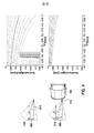
- the sensors 110 and 120 may each measure the exact velocity (here radial velocity 200 determined from the Doppler shift of the reflected radar beam compared to the radar beam emitted) of the colliding object 210, as shown in the right hand illustration Fig. 2 for the recognition of a punctual object is clarified.
- the left illustrations Fig. 2 For example, characteristics of the reflection intensity 220 are plotted against the radial velocity 230, the upper right representation representing measured values of the first sensor 110 and the lower right representation of FIG Fig. 2 represents the measured values of the second sensor 120. If a small point object 210 is centered on the vehicle 100, the two sensors will receive similar signals as shown in the right hand illustrations of FIGS Fig. 2 is reproduced.
- an extension of the object 210 can also be estimated via the reflection intensity 220.
- a difference quantity can be determined, which is determined from the determined radial frequencies of the first and second sensors 110 and 120.
- Fig. 3 is one too Fig. 2 reproduced analogous representation in which now the radial velocity of an extended object 210 to the Vehicle is determined to, from the lower right representation of the Fig. 3 a broader scattering of the radar beams reflected at the object 210 can be seen, from which consequently a broader dispersion of the different radial velocities 230 can be determined.
- the difference surface from the signal from the left sensor 110 and the signal from the right sensor 120 ie, in particular a signal from the first sensor 110-a signal from the second sensor 120
- it will be an extended object 210 that is to the right of the vehicle or at least on the right side of the vehicle 100.
- the difference surface of the signal of the left sensor 110 and the signal of the right sensor 120 ie in particular a signal of the first sensor 110 -a signal of the second sensor 120
- the total area is less than 0, then it is an offset of a punctual object 210.
- the offset of the object in relation to the vehicle can then be determined more accurately, for example, and also the orientation / angle to the ego vehicle can be derived.
- the offset results from the speed change.
- the radar sensor calculates the radial velocity of the object 210. By triangulating this information with analog information from the second sensor 120, the impact velocity can then be measured.
- the lateral offset 400 of the object can then be derived by means of trigonometry (for example, via sine / cosine calculations) or by previously determined comparison profiles.
- Such a determination of the offset is in the Fig. 4 shown, wherein in the upper two representations, a lateral offset of a point-shaped object 210 to a viewing direction 410 of the sensor in the direction of travel (left upper illustration of Figure 4 ) and an associated velocity profile of the radial velocity as a function of the offset (upper right representation of FIG Fig.
- an associated speed profile is shown, shown at a relative speed of 10 m / s between vehicle 100 and object 210 at a distance of 5 m between vehicle 100 and object 210 and an offset of 30 cm, wherein the object 210 has an extension of 40 cm (from the point of view of a sensor 110).
- the real speed curve will definitely be within the gray area.
- the boundary lines respectively correspond to the signal of a punctual object with an offset of 10 cm or 50 cm.
- Fig. 5 the determination of an impact angle of an object 210 on the vehicle 100 is shown schematically in more detail.
- the velocity profile for the incoming object 210 is shown, as shown by the first sensor 110 (left upper diagram Fig. 5 ) and the second sensor 120 (right upper diagram Fig. 5 ) are measured. It is in the two diagrams of the Fig. 5 the measured speed is plotted over a measuring time. From the two diagrams of Fig. 5 It can be clearly understood that the object 210 comes from a left side of the vehicle 100 and moves toward a right side of the vehicle 100.
- this radar sensor can also be replaced by another forward-looking sensor, such as an ultrasonic sensor.
- the detection of the speed of the incoming object 210 may be analogous when using an ultrasonic sensor; For example, it is also possible to evaluate a Doppler frequency shift of the ultrasound signal in order to be able to detect the speed of the incoming object in relation to the vehicle speed.
- the present invention also provides a method of impact protection in a collision of a vehicle with an object using data from at least one integrated sensor unit comprising at least one prospective sensor, in particular a radar sensor, and at least one acceleration sensor, the method comprising the steps of: receiving pre-data relating to the object via a pre-data interface from the look-ahead sensor, the pre-data representing at least one speed and / or distance of the object relative to the vehicle prior to the collision; Obtaining acceleration data via an acceleration data interface, wherein the acceleration data represents at least one acceleration of the vehicle after collision with the object; Combining the advance data with the acceleration data to form combination data, wherein the combination data particularly represents a collision velocity, a motion trajectory, and / or a distance of the object relative to the vehicle; and using the combination data in at least one impact protection device.
- the impact protection may be a protection against the consequences of the collision between the vehicle and the object, wherein the protection may extend to one or more occupants of the vehicle and / or the object.
- the object may be e.g. to act a pedestrian or cyclist.
- the integrated sensor unit may be a combination of two or more sensors.
- the combination may include a sensor that provides information that provides a period of time before the collision. This can e.g. be a radar sensor. Instead of the radar sensor, another sensor type can be used, which is designed to provide predictive data.
- the combination may include a sensor providing collision related information, e.g. about the impact severity, delivers. This can e.g. be an acceleration sensor.
- the acceleration sensor instead of the acceleration sensor, another sensor with which an impact severity can be detected, e.g. a pressure sensor, are used. Also combinations, e.g. from several radar sensors and / or acceleration sensors are possible.
- the sensor unit may also comprise a plurality of combinations of sensors spaced apart from each other, e.g. in a right or left side of a bumper of the vehicle, can be installed.
- the data may be, on the one hand, the advance data of the forward-looking sensor and, on the other hand, the acceleration data of the acceleration sensor, which are received via the corresponding interfaces, each sensor being equipped with its own interface.
- the combination data may include information describing both a pre-crash situation and the impact situation itself.
- the data may be information composed of the signals from the radar sensor and the acceleration sensor and output to various occupant protection systems prior to or at impact to provide impact protection.
- a further aspect of the invention is thus an implementation of a combined predictive crash sensor (PreCrash sensor) which, in addition to the acceleration data in the event of an impact, sends information about collision speed, trajectory and distance already before the impact.
- the predictive crash sensor may be considered as a combination of an acceleration sensor be realized with a one-chip radar. This can then be installed (for example, on both sides) in the bumper.
- the present invention provides a method 600 for determining a direction of movement of an object to be moved onto a vehicle, as shown in a flow chart in FIG Fig. 6 is shown.
- the method comprises a first step of receiving 620 a first sensor signal representing a speed of the object measured on the vehicle from a first signal measurement position on a left side of the vehicle viewed in the direction of travel.
- the method 600 comprises a step 640 of obtaining a second sensor signal, which represents a speed of the object measured on the vehicle from a second signal measurement position on the right side of the vehicle viewed in the direction of travel.
- the method 600 includes a further step of combining 660 the first sensor signal with the second sensor signal and information about a distance between the first and second signal measurement positions to determine a direction of movement of an object to be moved to the vehicle.
Abstract
Description
Die vorliegende Erfindung bezieht sich auf ein Verfahren zur Bestimmung einer Bewegungsrichtung eines sich auf ein Fahrzeug zu bewegenden Objektes gemäß Anspruch 1, ein Steuergerät gemäß Anspruch 9, ein Computerprogrammprodukt gemäß Anspruch 10 sowie ein Sensorsystem gemäß Anspruch 11.The present invention relates to a method for determining a direction of movement of an object to be moved onto a vehicle according to claim 1, a control device according to claim 9, a computer program product according to
Sensoren zur Fußgängererkennung, die im Bereich des Stoßfängers verbaut sind, sind bereits im Serieneinsatz und schon technisch sehr gut ausgereift. Des Weiteren sind periphere Sensoren zur Aufprallerkennung ebenfalls schon im Serieneinsatz. Zudem gibt es bereits Kombinationssensoren im Seitenbereich, wo beispielsweise ein Drucksensor mit einem Beschleunigungssensor in einem Gehäuse kombiniert ist. Ebenso ist die Doppelnutzung der Fußgängerschutzsensoren zur Aufprallerkennung und zur Unterstützung der Zentralsensorik bekannt. Zudem haben sich insbesondere Radarsensoren mittlerweile durch Fahrerassistenzfunktionen wie Abstandswarner und -regler (bspw. ACC = Adaptiv Cruise Control) oder Bremsfunktionen (beispielsweise AN B = Automatische Notbremsung) im Fahrzeug durchgesetzt. Auch im Bereich der passiven Sicherheit werden diese Sensoren mittlerweile genutzt um wichtige Informationen bereits vor dem Crash zu bekommen und entsprechend der Situation die Rückhaltemittel im Crash anzupassen.Sensors for pedestrian detection, which are installed in the bumper area, are already in production use and are already technically very well-engineered. Furthermore, peripheral sensors for impact detection are already in production use. In addition, there are already combination sensors in the side area, where, for example, a pressure sensor combined with an acceleration sensor in a housing. Likewise, the dual use of pedestrian protection sensors for impact detection and to support the central sensor is known. In addition, in particular radar sensors have now prevailed in the vehicle by driver assistance functions such as distance warning device and controller (eg ACC = Adaptive Cruise Control) or braking functions (for example AN B = automatic emergency braking). Even in the field of passive safety, these sensors are now used to get important information before the crash and adapt the restraints in a crash according to the situation.
Die
Vor diesem Hintergrund wird mit der vorliegenden Erfindung ein Verfahren zum Aufprallschutz, ein Steuergerät, das dieses Verfahren verwendet, weiterhin ein entsprechendes Computerprogrammprodukt, sowie schließlich ein Sensorsystem gemäß den unabhängigen Patentansprüchen vorgestellt. Vorteilhafte Ausgestaltungen ergeben sich aus den jeweiligen Unteransprüchen und der nachfolgenden Beschreibung.Against this background, the present invention proposes a method for impact protection, a control unit which uses this method, furthermore a corresponding computer program product, and finally a sensor system according to the independent patent claims. Advantageous embodiments emerge from the respective subclaims and the following description.
Die vorliegende Erfindung schafft ein Verfahren zur Bestimmung einer Bewegungsrichtung eines sich auf ein Fahrzeug zu bewegenden Objektes, wobei das Verfahren die folgenden Schritte aufweist:
- Empfangen eines ersten Sensorsignals, das eine von einer ersten Signalmessposition an einer in Fahrtrichtung gesehen linken Seite des Fahrzeugs oder einer Fahrzeugfront (beispielsweise mittels Radar) gemessene Geschwindigkeit des Objektes auf das Fahrzeug/den Sensor zu repräsentiert;
- Erhalten eines zweiten Sensorsignals, das eine von einer zweiten Signalmessposition an in Fahrtrichtung gesehen rechten Seite des Fahrzeugs oder einer Fahrzeugfront (beispielsweise mittels Radar) gemessene Geschwindigkeit des Objektes auf das Fahrzeug/den Sensor zu repräsentiert; und
- Verknüpfen des ersten Sensorsignals mit dem zweiten Sensorsignal und einer Information über einen Abstand zwischen der ersten und zweiten Signalmessposition, um eine Bewegungsrichtung und/oder-geschwindigkeit eines sich auf das Fahrzeug zu bewegenden Objektes zu bestimmen.
- Receiving a first sensor signal representative of a speed of the object to the vehicle / sensor measured from a first signal measurement position on a left side of the vehicle viewed in the direction of travel or a vehicle front (for example by means of radar);
- Obtaining a second sensor signal representative of a speed of the object to the vehicle / sensor as measured from a second signal measurement position on the right side of the vehicle as viewed in the direction of travel or of a vehicle front (for example by radar); and
- Linking the first sensor signal to the second sensor signal and information about a distance between the first and second signal measurement positions to determine a direction of movement and / or speed of an object to be moved to the vehicle.
Die vorliegende Erfindung schafft ferner ein Steuergerät, das ausgebildet ist, um die Schritte des erfindungsgemäßen Verfahrens durchzuführen bzw. umzusetzen. Auch durch diese Ausführungsvariante der Erfindung in Form eines Steuergeräts kann die der Erfindung zugrunde liegende Aufgabe schnell und effizient gelöst werden.The present invention further provides a control device which is designed to carry out or implement the steps of the method according to the invention. Also by this embodiment of the invention in the form of a control device, the object underlying the invention can be achieved quickly and efficiently.
Unter einem Steuergerät kann vorliegend ein elektrisches Gerät verstanden werden, das Sensorsignale verarbeitet und in Abhängigkeit davon Steuersignale ausgibt. Das Steuergerät kann eine Schnittstelle aufweisen, die hard- und/oder softwaremäßig ausgebildet sein kann. Bei einer hardwaremäßigen Ausbildung können die Schnittstellen beispielsweise Teil eines sogenannten System-ASICs sein, der verschiedenste Funktionen des Steuergeräts beinhaltet. Es ist jedoch auch möglich, dass die Schnittstellen eigene, integrierte Schaltkreise sind oder mindestens teilweise aus diskreten Bauelementen bestehen. Bei einer softwaremäßigen Ausbildung können die Schnittstellen Softwaremodule sein, die beispielsweise auf einem Mikrocontroller neben anderen Softwaremodulen vorhanden sind.In the present case, a control device can be understood to mean an electrical device which processes sensor signals and control signals in dependence thereon outputs. The control unit may have an interface, which may be formed in hardware and / or software. In the case of a hardware-based design, the interfaces can be part of a so-called system ASIC, for example, which contains various functions of the control unit. However, it is also possible that the interfaces are their own integrated circuits or at least partially consist of discrete components. In a software training, the interfaces may be software modules that are present, for example, on a microcontroller in addition to other software modules.
Von Vorteil ist auch ein Computerprogrammprodukt mit Programmcode, der auf einem maschinenlesbaren Träger wie einem Halbleiterspeicher, einem Festplattenspeicher oder einem optischen Speicher gespeichert ist und zur Durchführung des Verfahrens nach einem der vorstehend beschriebenen Ausführungsformen verwendet wird, wenn das Programm auf einem Steuergerät oder einer Datenverarbeitungseinheit ausgeführt wird.Also of advantage is a computer program product with program code which is stored on a machine-readable carrier such as a semiconductor memory, a hard disk memory or an optical memory and is used to carry out the method according to one of the embodiments described above, when the program is executed on a controller or a data processing unit becomes.
Auch schafft die vorliegende Erfindung ein Sensorsystem, das folgende Merkmale umfasst:
- einen ersten vorausschauenden Radarsensor, der an einer in Fahrtrichtung gesehen linken Seite des Fahrzeugs oder einer Fahrzeugfront verbaut ist und der ausgebildet ist, um ein erstes Sensorsignal zu liefern, das eine gemessene Geschwindigkeit des Objektes auf das Fahrzeug/den Sensor zu repräsentiert;
- einen zweiten vorausschauenden Radarsensor, der an einer in Fahrtrichtung gesehen rechten Seite des Fahrzeugs oder einer Fahrzeugfront verbaut ist, und der ausgebildet ist, um ein zweites Sensorsignal zu liefern, das eine gemessene Geschwindigkeit des Objektes auf das Fahrzeug/den Sensor zu repräsentiert; und
- eine Steuereinheit wie sie vorstehend beschrieben wurde.
- a first forward-looking radar sensor mounted on a left side of the vehicle or a vehicle front viewed in the direction of travel and configured to provide a first sensor signal representing a measured speed of the object to the vehicle / sensor;
- a second look-ahead radar sensor mounted on a right side of the vehicle or a vehicle front viewed in the direction of travel and configured to provide a second sensor signal representing a measured speed of the object to the vehicle / sensor; and
- a control unit as described above.
Die vorliegende Erfindung basiert auf der Erkenntnis, dass durch zwei Signale, die jeweils eine von unterschiedlichen Positionen aufgenommene Geschwindigkeit eines auf das Fahrzeug zu kommenden Objektes repräsentieren ein genauer Bewegungsweg dieses Objekts auf das Fahrzeug zu möglich wird. Hierbei wird zur Bestimmung des Bewegungswegs neben den beiden Signalen noch eine Information über den Abstand der beiden Positionen voneinander verwendet, von denen aus die Geschwindigkeit des auf das Fahrzeug zu kommenden Objekts gemessen wird. Diese kann beispielsweise mit Hilfe gemessener Entfernungsgates und zwischendurch interpolierten Werten hinreichend genau genug bestimmt werden. Die Geschwindigkeits- und Entfernungsinformationen können dann durch ein Triangulationsverfahren derart miteinander verknüpft werden, dass der Bewegungsweg des Objektes auf das Fahrzeug zu exakt bestimmbar ist.The present invention is based on the recognition that a precise movement path of this object towards the vehicle becomes possible by means of two signals, each representing a speed of an object approaching the vehicle, taken from different positions. In this case, to determine the path of movement in addition to the two signals even more information used by the distance of the two positions from each other, from which the speed of the approaching to the vehicle object is measured. This can be determined sufficiently accurately, for example, with the aid of measured distance gates and interpolated values in between. The speed and distance information can then be linked together by a triangulation method in such a way that the path of movement of the object to the vehicle is too precisely determinable.
Die vorliegende Erfindung bietet den Vorteil, dass nun technisch einfache und somit kostengünstige Radarsensoren an unterschiedlichen Positionen (beispielsweise im Frontbereich des Fahrzeugs, aber auch genauso an einer Fahrzeugseite) verbaut werden können und die Information aus den beiden Sensoren derart in einer Recheneinheit miteinander verknüpft werden können, dass aus den beiden einfachen Sensoren nun ein intelligenter "vorausschauender Sensor" gebildet werden kann. Zusätzlich besteht die Möglichkeit, in das Gehäuse der beiden Radarsensoren noch jeweils einen Beschleunigungssensor einzubauen, so dass ein Kombinationssensor aus technisch sehr einfachen und daher sehr kostengünstig herzustellenden Sensoren gebildet werden kann. Hierdurch kann nicht nur die Funktionalität des intelligenten "vorrausschauenden Sensors" bereitgestellt werden, vielmehr kann auch eine Plausibilisierung bei einem Aufprall des Objektes auf das Fahrzeug sehr einfach durchgeführt werden, da nun durch die erfasste Bewegungsrichtung des Objekts auf das Fahrzeug zu eine gewisse Vorwarnung über einen zeitlich unmittelbar nachfolgenden Aufprall des Objektes auf das Fahrzeug möglich ist.The present invention has the advantage that now technically simple and thus cost radar sensors can be installed at different positions (for example, in the front of the vehicle, but also on a vehicle side) and the information from the two sensors can be linked together in a computing unit in that an intelligent "anticipatory sensor" can now be formed from the two simple sensors. In addition, it is possible to install in the housing of the two radar sensors each still an acceleration sensor, so that a combination sensor of technically very simple and therefore very inexpensive to manufacture sensors can be formed. In this way, not only the functionality of the intelligent "forward-looking sensor" can be provided, but also a plausibility check on impact of the object on the vehicle can be performed very easily, since now by the detected direction of movement of the object on the vehicle to a certain advance warning over a Immediately subsequent impact of the object on the vehicle is possible.
In einer besonderen Ausführungsform der Erfindung kann im Schritt des Empfangens das erste Sensorsignal empfangen werden, das eine Information über eine Intensität eines von dem Objekt reflektierten Radarstrahls enthält und/oder es kann im Schritt des Erhaltens das zweite Sensorsignal erhalten werden, das eine Information über eine Intensität eines von dem Objekt reflektierten Radarstrahls enthält und wobei im Schritt des Verknüpfens ferner ein Abschätzen einer Ausdehnung des sich auf das Fahrzeug zu bewegenden Objektes unter Verwendung der Information über die Intensität aus dem ersten Sensorsignal und/oder unter Verwendung der Information über die Intensität aus dem zweiten Sensorsignal erfolgen kann. Eine derartige Ausführungsform der vorliegenden Erfindung bietet den Vorteil, dass neben einer Bewegungsrichtung des Objektes auf das Fahrzeug zu nun noch eine Abschätzung der Größe bzw. Breite des Objektes möglich ist. Dabei kann das erste und/oder zweite Sensorsignal lediglich software-technisch weiter aufbereitet werden und aus der Amplitude des entsprechenden Sensorsignals/die entsprechenden Sensorsignale die zusätzlichen Informationen gewonnen werden. Diese Informationen über die Größe des Objektes ermöglichen dann eine Abschätzung, wie schwer ein Aufprall des Objektes das Fahrzeug beschädigen würde und welche Sicherheitsmittel für den Insassenschutz mit welcher Stärke aktiviert werden sollten.In a particular embodiment of the invention, in the step of receiving, the first sensor signal containing information about an intensity of a radar beam reflected from the object can be received and / or the second sensor signal containing information about a second sensor signal can be obtained in the step of receiving Intensity of a radar beam reflected from the object, and wherein in the step of linking further estimating an extension of the object to be moved on the vehicle using the information about the intensity of the first sensor signal and / or using the information on the intensity of the second sensor signal can be done. Such an embodiment of the present invention offers the advantage that in addition to a direction of movement of the object on the Vehicle is still an estimate of the size or width of the object is possible. In this case, the first and / or second sensor signal can only be further processed by software engineering and the additional information can be obtained from the amplitude of the corresponding sensor signal / the corresponding sensor signals. This information on the size of the object then allows an estimate of how hard an impact of the object would damage the vehicle and what safety means should be activated for the occupant protection and with what strength.
In einer anderen Ausführungsform der Erfindung kann im Schritt des Empfangens das erste Sensorsignal empfangen werden, das eine Information über den zeitlichen Verlauf und der Sensorsignaländerung enthält und/oder wobei im Schritt des Erhaltens das zweite Sensorsignal werden kann, das eine Information über den zeitlichen Verlauf und der Sensorsignaländerung enthält und wobei im Schritt des Verknüpfens ferner ein Abschätzen einer Position (laterale Orientierung) des sich auf das Fahrzeug zu bewegenden Objektes unter Verwendung der Information aus dem zeitlichen Verlauf der Signaländerung und/oder unter Verwendung der Information aus dem zeitlichen Verlauf der Signaländerung erfolgen kann. Eine derartige Ausführungsform der vorliegenden Erfindung bietet den Vorteil, dass neben der bestimmten Bewegungsrichtung noch ein laterale Orientierung des Objektes von dem Fahrzeug ermittelt werden kann, so dass neben der Bestimmung der Bewegungsrichtung auch eine sehr präzise Positionserkennung des Objektes in Bezug zum Fahrzeug möglich wird. Dies verbessert eine Abschätzung des Aufprallzeitpunkts des Objektes auf das Fahrzeug und ermöglicht somit eine präzisere Ansteuerung der entsprechenden Sicherheitsmittel, die die Folgen des Aufpralls auf das Fahrzeug kompensieren oder zumindest abschwächen sollen.In another embodiment of the invention, in the step of receiving the first sensor signal may be received, which contains information about the time course and the sensor signal change and / or wherein in the step of obtaining the second sensor signal can be, which information about the time course and the sensor signal change contains and wherein in the step of linking further estimation of a position (lateral orientation) of the moving object to the vehicle using the information from the time course of the signal change and / or using the information from the time course of the signal change can. Such an embodiment of the present invention has the advantage that, in addition to the specific direction of movement, a lateral orientation of the object can still be determined by the vehicle, so that not only the determination of the direction of movement but also a very precise position detection of the object with respect to the vehicle becomes possible. This improves an estimate of the impact time of the object on the vehicle and thus enables a more precise control of the corresponding safety means, which should compensate for or at least mitigate the consequences of the impact on the vehicle.
Günstig ist es ferner, wenn im Schritt des Verknüpfens eine Position des Objektes in Bezug zum Fahrzeug auf der Basis einer Differenzgröße bestimmt wird, wobei zur Ermittlung der Differenzgröße eine Differenz zwischen einer durch das erste Sensorsignal repräsentierten Frequenz oder Geschwindigkeit und einer durch das zweite Sensorsignal repräsentierten Frequenz oder Geschwindigkeit gebildet wird. Eine derartige Ausführungsform der vorliegenden Erfindung bietet den Vorteil, dass durch technisch sehr einfach zu realisierende Algorithmenfunktionen bereits eine grobe Positionsbestimmung des Objektes in Bezug zum Fahrzeug möglich wird. Eine solche technisch sehr einfach zu realisieren der Funktion wird insbesondere dann zusätzlich vereinfacht, wenn speziell ein Vorzeichen der Differenzgröße ausgewertet wird. So kann beispielsweise im Schritt des Verknüpfens eine Position des Objektes mittig zum Fahrzeug erkannt werden, wenn die Differenzgröße innerhalb eines Toleranzbereiches um einen Wert von Null liegt. Auch kann in einer anderen Ausführungsform der Erfindung im Schritt des Verknüpfens eine Position des Objekts in die Fahrtrichtung gesehen auf der rechten Fahrzeugseite erkannt werden, wenn die Differenzgröße einen positiven Wert aufweist. Alternativ oder zusätzlich kann auch im Schritt des Verknüpfens eine Position des Objektes in die Fahrtrichtung gesehen linke Seite erkannt werden, wenn die Differenzgröße einen negativen Wert aufweist. Oder umgekehrt, je nach Subtraktionsformel. Ähnliche Erkenntnisse lassen sich unter Umständen auch über eine Division erreichen.It is also favorable if, in the step of linking, a position of the object relative to the vehicle is determined on the basis of a difference quantity, a difference between a frequency or speed represented by the first sensor signal and a signal represented by the second sensor signal being used to determine the difference magnitude Frequency or speed is formed. Such an embodiment of the present invention offers the advantage that a coarse position determination of the object with respect to the. By very simple to implement algorithm functions Vehicle becomes possible. Such a technically very simple to implement the function is especially simplified in addition, especially when a sign of the difference size is evaluated. For example, in the step of linking a position of the object can be detected centrally to the vehicle when the difference size is within a tolerance range by a value of zero. Also, in another embodiment of the invention, in the step of linking, a position of the object in the traveling direction can be recognized on the right side of the vehicle when the difference amount has a positive value. Alternatively or additionally, a position of the object in the direction of travel seen left side can be detected in the step of linking, if the difference size has a negative value. Or vice versa, depending on the subtraction formula. Under similar circumstances, similar findings can also be achieved by means of a division.
Gemäß einer weiteren Ausführungsform der Erfindung kann das Verfahren ferner einen Schritt des Empfangens eines dritten Sensorsignals aufweisen, das eine Beschleunigung zumindest einer Komponente des Fahrzeugs repräsentiert, die größer als ein Beschleunigungsschwellwert ist, wobei das Verfahren weiterhin einen Schritt des Aktivierens eines Fahrzeuginsassenschutzmittels umfasst, wenn zeitlich nach einer bestimmten Bewegungsrichtung des Objektes in Richtung des Fahrzeugs das dritte Sensorsignal empfangen wird. Eine derartige Ausführungsform der vorliegenden Erfindung bietet den Vorteil, dass beispielsweise mittels eines integrierten Sensors einerseits das erste Sensorsignal (beispielsweise als Radarsignal) erfasst werden kann, wogegen das dritte Sensorsignal eine Beschleunigung beim Aufprall des Objekt auf das Fahrzeug repräsentiert, das durch einen Beschleunigungssensor bestimmt wird, der zusammen mit dem entsprechenden Radarsensor in einem integrierten Sensor verbaut ist. Auf diese Weise können Herstellungskosten für das Fahrzeug gesenkt werden da lediglich ein einfacher und somit kostengünstiger integrierter Sensor an einer bzw. zwei Positionen im Fahrzeug verbaut werden braucht. Dennoch kann eine sehr gute Plausibilisierung eines Aufpralls eines Objektes auf das Fahrzeug erfolgen, da durch die Abschätzung der Bewegungsrichtung des Objektes auf das Fahrzeug eine kurz danach auftretende Beschleunigung durch den Einschlag als "Aufprall des Objektes auf das Fahrzeug" plausibilisiert werden kann. Das dritte Sensorsignal kann auch aus mehreren anderen beschleunigungsbasierten Sensorsignalen erzeugt werden.According to another embodiment of the invention, the method may further comprise a step of receiving a third sensor signal representing an acceleration of at least one component of the vehicle greater than an acceleration threshold, the method further comprising a step of activating a vehicle occupant protection means, as appropriate after a certain direction of movement of the object in the direction of the vehicle, the third sensor signal is received. Such an embodiment of the present invention has the advantage that, for example, by means of an integrated sensor on the one hand, the first sensor signal (for example, as a radar signal) can be detected, whereas the third sensor signal represents an acceleration in the impact of the object on the vehicle, which is determined by an acceleration sensor , which is installed together with the corresponding radar sensor in an integrated sensor. In this way, manufacturing costs for the vehicle can be reduced because only a simple and thus cost-integrated sensor needs to be installed at one or two positions in the vehicle. Nevertheless, a very good plausibility check of an impact of an object on the vehicle can be carried out, since the estimation of the direction of movement of the object on the vehicle, a shortly occurring acceleration by the impact as "impact of the object on the vehicle" can be plausibility. The third sensor signal can also be generated from a plurality of other acceleration-based sensor signals.
Die Erfindung wird anhand der beigefügten Zeichnungen beispielhaft näher erläutert. Es zeigen:
-
Fig. 1 ein Blockschaltbild eines ersten Ausführungsbeispiels der vorliegenden Erfindung, bei dem ein Systemaufbau mit zwei Sensoren und einem zentralen Steuergerät verwendet wird; -
Fig. 2 eine Darstellung der Verteilung der Differenzreflexionen als Radialgeschwindigkeit dargestellt für ein punktuelles Objekt; -
Fig. 3 eine Darstellung der Verteilung der Differenzreflexionen als Radialgeschwindigkeit dargestellt für ein ausgedehntes Objekt; -
Fig. 4 eine Darstellung des Verlaufs der Radialgeschwindigkeiten für ein punktuelles und ausgedehntes Objekt mit unterschiedlichem Versatz; -
Fig. 5 eine Darstellung des Verlaufs der Radialgeschwindigkeiten für ein punktuelles Objekt, was in einem Winkel auf das betrachtete Fahrzeug zukommt. Im Hintergrund sind als Hilfe die Verläufe von einem Objekt mit Versatz dargestellt; und -
Fig. 6 ein Ablaufdiagramm eines Ausführungsbeispiels der vorliegenden Erfindung als Verfahren.
-
Fig. 1 a block diagram of a first embodiment of the present invention, in which a system structure is used with two sensors and a central controller; -
Fig. 2 a representation of the distribution of differential reflections as a radial velocity shown for a point object; -
Fig. 3 a representation of the distribution of differential reflections as a radial velocity shown for an extended object; -
Fig. 4 a representation of the course of the radial velocities for a punctual and extended object with different offset; -
Fig. 5 a representation of the course of the radial velocities for a point object, which is at an angle to the considered vehicle. In the background, the progressions of an object with offset are shown as help; and -
Fig. 6 a flowchart of an embodiment of the present invention as a method.
Gleiche oder ähnliche Elemente können in den Figuren durch gleiche oder ähnliche Bezugszeichen versehen sein, wobei auf eine wiederholte Beschreibung verzichtet wird. Ferner enthalten die Figuren der Zeichnungen, deren Beschreibung sowie die Ansprüche zahlreiche Merkmale in Kombination. Einem Fachmann ist dabei klar, dass diese Merkmale auch einzeln betrachtet werden oder sie zu weiteren, hier nicht explizit beschriebenen Kombinationen zusammengefasst werden können. Weiterhin ist die Erfindung in der nachfolgenden Beschreibung unter Verwendung von unterschiedlichen Maßen und Dimensionen erläutert, wobei die Erfindung nicht auf diese Maße und Dimensionen eingeschränkt zu verstehen ist. Ferner können erfindungsgemäße Verfahrensschritte wiederholt sowie in einer anderen als in der beschriebenen Reihenfolge ausgeführt werden. Umfasst ein Ausführungsbeispiel eine "und/oder" Verknüpfung zwischen einem ersten Merkmal und einem zweites Merkmal, so kann dies so gelesen werden, dass das Ausführungsbeispiel gemäß einer Ausführungsform sowohl das erste Merkmal als auch das zweite Merkmal und gemäß einer weiteren Ausführungsform entweder nur das erste Merkmal oder nur das zweite Merkmal aufweist.
Wird nun in der zentralen Auswerteeinheit 130 eine Bewegungsrichtung eines Objektes auf das Fahrzeug 100 zu erkannt, können bereits vor einem Aufprall des Objektes auf das Fahrzeug 100 bestimmte Insassenschutzmittel aktiviert oder in einen erhöhten Alarmzustand versetzt werden. Beispielsweise kann eine Auslöseschwelle für einen Insassenairbag 160 herunter gesetzt werden oder die Information über das ankommende Objekt als Plausibilisierungssignal für eine Auslösung dieses Insassenairbag 160 verwendet werden. Alternativ oder zusätzlich kann beispielsweise ein Gurtstraffer 170 aktiviert werden, um vor einem Aufprall des Objekts auf das Fahrzeug einen Fahrzeuginsassen in einer für die Schutzwirkung eines Airbags optimalen Position zu halten oder zu bringen.If a direction of movement of an object toward the
Sind nun im ersten Sensor 110 und/oder dem zweiten Sensor 120 ebenfalls Beschleunigungssensoren verbaut, können Signale dieser Beschleunigungssensoren bei einem Aufprall des Objekt auf das Fahrzeug 100 in der zentralen Auswerteeinheit 130 verwendet werden, um zusammen mit dem vorab gelieferten Signalen der Radar(teil)sensoren des ersten Sensors 110 oder des zweiten Sensors 120 sowohl eine Auslösung als auch eine Plausibilisierung der Auslösung eines Insassenschutzmittels im Fahrzeug zu bewirken. Dadurch, dass im ersten Sensor 110 und den zweiten Sensor 120 dann Sensoren für unterschiedliche physikalische Größen (beispielsweise in einem gemeinsamen Gehäuse) verbaut sind kann eine Montage dieser Sensoren für die unterschiedlichen physikalischen Größen sehr kostengünstig und dennoch funktional effizient erfolgen. Weiterhin brauchen für eine Grundfunktionalität der vorliegenden Erfindung auch keine teuren Radarsensoren verwendet werden; vielmehr reichen einfache und daher kostengünstige Sensoren aus, die bereits eine Messung der Geschwindigkeit des Objekts auf das Fahrzeug zu ermöglichen.If acceleration sensors are also installed in the
Ein Billig-Radarsensor alleine, also ein Sensor, der eine kurze Reichweite hat (meist unter 5 m) und weder mehrere Objekte im Erfassungsbereich von einander direkt unterscheiden kann, noch die exakte Position bestimmen kann (allerhöchstens Entfernungsbereiche festgelegt sind), kann die geforderten Informationen zur Bestimmung der Bewegungsrichtung des Objektes in der Regel alleine nicht direkt liefern. Diese notwendigen Informationen sollen nun, ohne dass der Sensor wieder teurer wird, in der Nachverarbeitung softwareseitig erzeugt werden.A low-cost radar sensor alone, so a sensor that has a short range (usually less than 5 m) and neither directly different from each other in the detection range of each other, nor can determine the exact position (at most distance ranges are fixed), the required information to determine the direction of movement of the object usually not alone deliver directly. This necessary information should now, without the sensor is expensive again, be generated in the post-processing software.
Ein wichtiger Teil der Erfindung ist somit darin zu sehen, eine Realisierung eines billigen (beispielsweise Radar-) Sensors zu ermöglichen, der die notwendigen Informationen, wie Objektausdehnung, Orientierung etc. aus den Radarreflexionen softwareseitig herleitet. Gerade in der passiven Sicherheit bietet sich ein solcher Sensor an, da er zum einen sehr günstig, zum anderen die geringe Reichweite vollkommen ausreichend ist.An important part of the invention is therefore to be seen in enabling a realization of a cheap (for example radar) sensor, which derives the necessary information, such as object extent, orientation, etc. from the radar reflections on the software side. Especially in passive safety, such a sensor offers, as it is on the one hand very cheap, on the other hand, the short range is completely sufficient.
Wie bereits vorstehend mit Bezug auf die
Die Sensoren 110 und 120 können jeweils die exakte Geschwindigkeit (hier Radialgeschwindigkeit 200, die aus der Dopplerverschiebung des reflektierten Radarstrahls im Vergleich zum ausgesandten Radarstrahl bestimmt wird) des kollidierenden Objektes 210 messen, wie dies in der rechten Darstellung aus
Durch die Verwendung von zwei Sensoren (und beispielsweise einer groben Klassifikation in Entfernungsgates (Distance-Gates), durch die ein grober Abstand des Objektes 210 vom Fahrzeug 100 bestimmt wird) kann die Position des Objektes longitudinal (bei Verwendung des zeitlichen Verlaufs) und/oder lateral bestimmt und die Aufprallgeschwindigkeit ermittelt werden. Longitudinal wird zwar direkt vom Sensor 110 nur ein Entfernungsbereich angegeben oder bestimmt, allerdings durch eine Triangulation mit der Information des zweiten Sensors 120 (und evtl. dem Abstand zwischen dem ersten und zweiten Sensor), kann die Entfernung des Objektes 210 ab Eintritt in den Entfernungsbereich 140 bzw. 150 mit Hilfe der gemessenen und berechneten Geschwindigkeitsinformationen (Radialgeschwindigkeiten und Aufprallgeschwindigkeit) gut geschätzt (d.h. bestimmt bzw. interpoliert) werden, was aus der
- Ist Differenz des Signals vom linken
Sensor 110 zum rechten Sensor 120 (d.h. insbesondere das Signal des ersten Sensors 110 - das Signal des zweiten Sensors 120)nahezu konstant 0, lässt dies darauf schließen, dass es sich beidem Objekt 210 um ein punktuelles Objekt handelt, das mittig zumFahrzeug 100 ausgerichtet ist und aufdas Fahrzeug 100 zukommt. Alternativ kann es sich beidem Objekt 210 um ein ausgedehntes Objekt handeln, das symmetrisch um die Fahrzeugmitte ausgerichtet ist und aufdas Fahrzeug 100 zukommt.
- If the difference of the signal from the
left sensor 110 to the right sensor 120 (ie in particular the signal of the first sensor 110 - the signal of the second sensor 120) is almost constant 0, this indicates that theobject 210 is a punctiform object centered on thevehicle 100 and approaching thevehicle 100. Alternatively, theobject 210 may be an extended object symmetrically aligned about the vehicle center and approaching thevehicle 100.
Ist die Differenzfläche aus dem Signal vom linken Sensor 110 und dem Signal des rechten Sensors 120 (d.h. insbesondere ein Signal des ersten Sensors 110-ein Signal des zweiten Sensors 120) vollständig positiv, dann wird es sich um ein ausgedehntes Objekt 210 handeln, das sich rechts vom Fahrzeug oder zumindest auf der rechten Seite des Fahrzeugs 100 befindet.If the difference surface from the signal from the
Ist die Differenzfläche aus dem Signal des linken Sensors 110 und dem Signal des rechten Sensors 120 (d.h. insbesondere das Signal des ersten Sensors 110 - das Signal des zweiten Sensors 120) vollständig negativ, ist von einem ausgedehnten Objekt 210 auszugehen, das sich links vom Fahrzeug oder auf der linken Seite des Fahrzeugs 100 befindet.If the difference surface of the signal of the
Ist die Differenzfläche aus dem Signal des linken Sensors 110 und dem Signal des rechten Sensors 120 (d.h. insbesondere ein Signal des ersten Sensors 110-ein Signal des zweiten Sensors 120) für einige Zeitintervalle positiv und für einige negativ, die Gesamtfläche kleiner als 0, dann handelt es sich um einen Versatz eines punktuellen Objekts 210.If the difference surface of the signal of the
Durch die dynamische Veränderung dieser erzeugten (Signal-) Werte, kann dann beispielsweise anschließend noch der Versatz des Objektes in Bezug zum Fahrzeug genauer bestimmt werden und ebenfalls die Orientierung/Winkel zum Ego-Fahrzeug hergeleitet werden.Due to the dynamic change of these generated (signal) values, the offset of the object in relation to the vehicle can then be determined more accurately, for example, and also the orientation / angle to the ego vehicle can be derived.
Der Versatz ergibt sich dabei durch die Geschwindigkeitsänderung. Der Radarsensor berechnet ja die Radialgeschwindigkeit des Objektes 210. Durch Triangulation dieser Information mit einer analogen Information vom zweiten Sensor 120, kann dann die Aufprallgeschwindigkeit gemessen werden. Durch die jeweilige Änderung der Radialgeschwindigkeit kann dann der laterale Versatz 400 des Objektes mittels Trigonometrie (beispielsweise über Sinus/Cosinus-Berechnungen) oder durch vorher bestimmte Vergleichsverläufe hergeleitet werden. Eine solche Bestimmung des Versatzes ist in der
Der Winkel, mit dem sich das Objekt 210 auf das Fahrzeug 100 zu bewegt, kann dann ähnlich bestimmt werden, nur dass hier wesentlich größere Änderungen auftreten. In
Schließlich ist anzumerken, dass der vorstehend genannte Ansatz zur Bestimmung einer Bewegungsrichtung eines auf das Fahrzeug zu kommenden Objektes unter Verwendung eines Radarsensors beschrieben wurde. Dieser Radarsensor kann aber auch durch einen anderen vorausschauenden Sensor ersetzt werden, wie beispielsweise einen Ultraschallsensor. Die Erfassung der Geschwindigkeit des ankommenden Objektes 210 kann bei der Verwendung eines Ultraschallsensors analog erfolgen; es kann beispielsweise ebenfalls eine Dopplerfrequenzverschiebung des Ultraschallsignals ausgewertet werden, um die Geschwindigkeit des ankommenden Objektes in Bezug zur Fahrzeuggeschwindigkeit erfassen zu können.Finally, it should be noted that the above-mentioned approach for determining a direction of movement of an object approaching the vehicle using a radar sensor has been described. However, this radar sensor can also be replaced by another forward-looking sensor, such as an ultrasonic sensor. The detection of the speed of the
Die vorliegende Erfindung schafft auch ein Verfahren zum Aufprallschutz bei einem Zusammenprall eines Fahrzeugs mit einem Objekt unter Verwendung von Daten mindestens einer integrierten Sensoreinheit, die mindestens einen vorausschauenden Sensor, insbesondere einen Radarsensor, und mindestens einen Beschleunigungssensor aufweist, wobei das Verfahren folgende Schritte aufweist: Empfangen von Vorausdaten bezüglich des Objekts über eine Vorausdatenschnittstelle von dem vorausschauenden Sensor, wobei die Vorausdaten mindestens eine Geschwindigkeit und/oder eine Entfernung des Objektes bezüglich des Fahrzeugs vor dem Zusammenprall repräsentieren; Erhalten von Beschleunigungsdaten über eine Beschleunigungsdatenschnittstelle, wobei die Beschleunigungsdaten mindestens eine Beschleunigung des Fahrzeugs nach dem Zusammenprall mit dem Objekt repräsentieren; Kombinieren der Vorausdaten mit den Beschleunigungsdaten zur Bildung von Kombinationsdaten, wobei die Kombinationsdaten insbesondere eine Kollisionsgeschwindigkeit, eine Bewegungstrajektorie und/oder eine Entfernung des Objektes in Bezug zum Fahrzeug repräsentieren; und Verwenden der Kombinationsdaten in mindestens einer Vorrichtung zum Aufprallschutz.The present invention also provides a method of impact protection in a collision of a vehicle with an object using data from at least one integrated sensor unit comprising at least one prospective sensor, in particular a radar sensor, and at least one acceleration sensor, the method comprising the steps of: receiving pre-data relating to the object via a pre-data interface from the look-ahead sensor, the pre-data representing at least one speed and / or distance of the object relative to the vehicle prior to the collision; Obtaining acceleration data via an acceleration data interface, wherein the acceleration data represents at least one acceleration of the vehicle after collision with the object; Combining the advance data with the acceleration data to form combination data, wherein the combination data particularly represents a collision velocity, a motion trajectory, and / or a distance of the object relative to the vehicle; and using the combination data in at least one impact protection device.
Bei dem Aufprallschutz kann es sich um einen Schutz vor den Folgen des Zusammenpralls zwischen dem Fahrzeug und dem Objekt handeln, wobei der Schutz sich auf einen oder mehrere Insassen des Fahrzeugs und/oder des Objekts erstrecken kann. Bei dem Objekt kann es sich z.B. um einen Fußgänger oder Radfahrer handeln. Bei der integrierten Sensoreinheit kann es sich um eine Kombination aus zwei oder mehreren Sensoren handeln. Die Kombination kann einen Sensor umfassen, der Informationen liefert, die einen gewissen Zeitraum vor dem Zusammenprall liefert. Dies kann z.B. ein Radarsensor sein. Anstelle des Radarsensors kann auch ein anderer Sensortyp eingesetzt werden, der ausgebildet ist, um vorausschauende Daten zu liefern. Daneben kann die Kombination einen Sensor umfassen, der auf den Zusammenprall bezogene Informationen, z.B. über die Aufprallschwere, liefert. Dies kann z.B. ein Beschleunigungssensor sein. Ebenso kann anstelle des Beschleunigungssensors ein anderer Sensor, mit dem eine Aufprallschwere erfasst werden kann, z.B. ein Drucksensor, zum Einsatz kommen. Auch Kombinationen z.B. aus mehreren Radarsensoren und/oder Beschleunigungssensoren sind möglich. Die Sensoreinheit kann auch mehrere Kombinationen von Sensoren umfassen, die örtlich voneinander entfernt, z.B. in einer rechten oder linken Seite eines Stoßfängers des Fahrzeugs, verbaut sein können. Bei den Daten kann es sich zum einen um die Vorausdaten des vorausschauenden Sensors und zum anderen um die Beschleunigungsdaten des Beschleunigungssensors handeln, die über die entsprechenden Schnittstellen empfangen werden, wobei jeder Sensor mit einer eigenen Schnittstelle ausgestattet ist. Folglich können die Kombinationsdaten Informationen umfassen, die sowohl eine Situation vor dem Aufprall beschreiben als auch die Aufprallsituation selbst wiedergeben.The impact protection may be a protection against the consequences of the collision between the vehicle and the object, wherein the protection may extend to one or more occupants of the vehicle and / or the object. The object may be e.g. to act a pedestrian or cyclist. The integrated sensor unit may be a combination of two or more sensors. The combination may include a sensor that provides information that provides a period of time before the collision. This can e.g. be a radar sensor. Instead of the radar sensor, another sensor type can be used, which is designed to provide predictive data. In addition, the combination may include a sensor providing collision related information, e.g. about the impact severity, delivers. This can e.g. be an acceleration sensor. Likewise, instead of the acceleration sensor, another sensor with which an impact severity can be detected, e.g. a pressure sensor, are used. Also combinations, e.g. from several radar sensors and / or acceleration sensors are possible. The sensor unit may also comprise a plurality of combinations of sensors spaced apart from each other, e.g. in a right or left side of a bumper of the vehicle, can be installed. The data may be, on the one hand, the advance data of the forward-looking sensor and, on the other hand, the acceleration data of the acceleration sensor, which are received via the corresponding interfaces, each sensor being equipped with its own interface. Thus, the combination data may include information describing both a pre-crash situation and the impact situation itself.
Bei den Daten kann es sich um Informationen handeln, die aus den Signalen des Radarsensors und des Beschleunigungssensors zusammengesetzt sind und an verschiedene Insassenschutzsysteme vor oder mit dem Zusammenprall ausgegeben werden können, um den Aufprallschutz zu gewährleisten.The data may be information composed of the signals from the radar sensor and the acceleration sensor and output to various occupant protection systems prior to or at impact to provide impact protection.
Ein weiterer Aspekt der Erfindung ist somit eine Realisierung eines kombinierten vorausschauenden Unfallsensors (PreCrash-Sensors), der neben den Beschleunigungsdaten im Fall eines Aufpralls bereits unmittelbar vor dem Aufprall Informationen über Kollisionsgeschwindigkeit, Trajektorie und Entfernung schickt. Der vorausschauende Unfallsensor kann als eine Kombination aus einem Beschleunigungssensor mit einem Ein-Chip-Radar realisiert werden. Dieser kann dann (beispielsweise beidseitig) im Stoßfänger verbaut werden.A further aspect of the invention is thus an implementation of a combined predictive crash sensor (PreCrash sensor) which, in addition to the acceleration data in the event of an impact, sends information about collision speed, trajectory and distance already before the impact. The predictive crash sensor may be considered as a combination of an acceleration sensor be realized with a one-chip radar. This can then be installed (for example, on both sides) in the bumper.
Ferner schafft die vorliegende Erfindung ein Verfahren 600 zur Bestimmung einer Bewegungsrichtung eines sich auf ein Fahrzeug zu bewegenden Objektes, wie es als Ablaufdiagramm in
Claims (11)
Applications Claiming Priority (1)
| Application Number | Priority Date | Filing Date | Title |
|---|---|---|---|
| DE102009047390A DE102009047390A1 (en) | 2009-12-02 | 2009-12-02 | Method and control device for determining a direction of movement an object to be moved onto a vehicle |
Publications (3)
| Publication Number | Publication Date |
|---|---|
| EP2333578A2 true EP2333578A2 (en) | 2011-06-15 |
| EP2333578A3 EP2333578A3 (en) | 2012-02-29 |
| EP2333578B1 EP2333578B1 (en) | 2015-11-25 |
Family
ID=43640164
Family Applications (1)
| Application Number | Title | Priority Date | Filing Date |
|---|---|---|---|
| EP10193185.5A Not-in-force EP2333578B1 (en) | 2009-12-02 | 2010-11-30 | Method and control device for determining a movement direction of an object moving towards a vehicle |
Country Status (2)
| Country | Link |
|---|---|
| EP (1) | EP2333578B1 (en) |
| DE (1) | DE102009047390A1 (en) |
Cited By (8)
| Publication number | Priority date | Publication date | Assignee | Title |
|---|---|---|---|---|
| EP2631125A1 (en) * | 2012-02-24 | 2013-08-28 | Robert Bosch Gmbh | Method and device for checking the plausibility of a predictive sensor system |
| EP2887093A1 (en) * | 2013-12-21 | 2015-06-24 | Valeo Schalter und Sensoren GmbH | Method for classifying an object, sensor device and motor vehicle |
| WO2017114603A1 (en) * | 2015-12-28 | 2017-07-06 | Robert Bosch Gmbh | Method for correcting at least one collision parameter and corresponding integrated safety system for a vehicle |
| EP3418768A1 (en) * | 2017-06-20 | 2018-12-26 | Veoneer Sweden AB | A vehicle radar system comprising two radar sensor arrangements |
| CN109557535A (en) * | 2017-09-26 | 2019-04-02 | 英飞凌科技股份有限公司 | System and method for using the occupancy detection of millimetre-wave radar sensor |
| CN109581379A (en) * | 2017-09-28 | 2019-04-05 | 德尔福技术有限责任公司 | The method of the radar system of vehicle and under static state test object |
| CN109642943A (en) * | 2016-07-08 | 2019-04-16 | 维宁尔瑞典公司 | Vehicle radar system |
| CN114424265A (en) * | 2019-09-25 | 2022-04-29 | 索尼集团公司 | Signal processing device, signal processing method, program, and mobile device |
Families Citing this family (1)
| Publication number | Priority date | Publication date | Assignee | Title |
|---|---|---|---|---|
| DE102017101772A1 (en) | 2017-01-30 | 2018-09-06 | Valeo Schalter Und Sensoren Gmbh | Method for detecting an object in an environmental region of a motor vehicle by means of a radar sensor with determination of dimensions of the object, radar sensor, driver assistance system and motor vehicle |
Citations (1)
| Publication number | Priority date | Publication date | Assignee | Title |
|---|---|---|---|---|
| DE102006036934A1 (en) | 2006-08-08 | 2008-02-14 | Robert Bosch Gmbh | Device for a vehicle comprises a vehicle sensor unit and a vehicle structural component belonging to different vehicle systems |
Family Cites Families (4)
| Publication number | Priority date | Publication date | Assignee | Title |
|---|---|---|---|---|
| GB2327821B (en) * | 1997-05-17 | 1999-12-01 | Bosch Gmbh Robert | Method and device for detecting an imminent or possible collision |
| DE10342128A1 (en) * | 2003-09-12 | 2005-04-07 | Valeo Schalter Und Sensoren Gmbh | Method and distance detection device for determining the distance between at least one sensor device and an object |
| US20060091654A1 (en) * | 2004-11-04 | 2006-05-04 | Autoliv Asp, Inc. | Sensor system with radar sensor and vision sensor |
| JP2009031078A (en) * | 2007-07-26 | 2009-02-12 | Omron Corp | Device and method for detection |
-
2009
- 2009-12-02 DE DE102009047390A patent/DE102009047390A1/en not_active Withdrawn
-
2010
- 2010-11-30 EP EP10193185.5A patent/EP2333578B1/en not_active Not-in-force
Patent Citations (1)
| Publication number | Priority date | Publication date | Assignee | Title |
|---|---|---|---|---|
| DE102006036934A1 (en) | 2006-08-08 | 2008-02-14 | Robert Bosch Gmbh | Device for a vehicle comprises a vehicle sensor unit and a vehicle structural component belonging to different vehicle systems |
Cited By (11)
| Publication number | Priority date | Publication date | Assignee | Title |
|---|---|---|---|---|
| EP2631125A1 (en) * | 2012-02-24 | 2013-08-28 | Robert Bosch Gmbh | Method and device for checking the plausibility of a predictive sensor system |
| EP2887093A1 (en) * | 2013-12-21 | 2015-06-24 | Valeo Schalter und Sensoren GmbH | Method for classifying an object, sensor device and motor vehicle |
| WO2017114603A1 (en) * | 2015-12-28 | 2017-07-06 | Robert Bosch Gmbh | Method for correcting at least one collision parameter and corresponding integrated safety system for a vehicle |
| US11007959B2 (en) | 2015-12-28 | 2021-05-18 | Robert Bosch Gmbh | Method for correcting at least one collision parameter and corresponding integrated safety system for a vehicle |
| CN109642943A (en) * | 2016-07-08 | 2019-04-16 | 维宁尔瑞典公司 | Vehicle radar system |
| US11762084B2 (en) | 2016-07-08 | 2023-09-19 | Arriver Software Ab | Vehicle radar system |
| EP3418768A1 (en) * | 2017-06-20 | 2018-12-26 | Veoneer Sweden AB | A vehicle radar system comprising two radar sensor arrangements |
| CN109557535A (en) * | 2017-09-26 | 2019-04-02 | 英飞凌科技股份有限公司 | System and method for using the occupancy detection of millimetre-wave radar sensor |
| CN109557535B (en) * | 2017-09-26 | 2023-12-08 | 英飞凌科技股份有限公司 | System and method for occupancy detection using millimeter wave radar sensors |
| CN109581379A (en) * | 2017-09-28 | 2019-04-05 | 德尔福技术有限责任公司 | The method of the radar system of vehicle and under static state test object |
| CN114424265A (en) * | 2019-09-25 | 2022-04-29 | 索尼集团公司 | Signal processing device, signal processing method, program, and mobile device |
Also Published As
| Publication number | Publication date |
|---|---|
| EP2333578B1 (en) | 2015-11-25 |
| DE102009047390A1 (en) | 2011-06-09 |
| EP2333578A3 (en) | 2012-02-29 |
Similar Documents
| Publication | Publication Date | Title |
|---|---|---|
| EP2333578B1 (en) | Method and control device for determining a movement direction of an object moving towards a vehicle | |
| DE102015219551B4 (en) | Object detection device | |
| EP2242674B1 (en) | Method and assistance system for detecting objects in the surrounding area of a vehicle | |
| DE102014103695A1 (en) | Vehicle based intersection assessment device and program | |
| DE102012216386A1 (en) | Method for operating a driver assistance system of a vehicle | |
| DE112015004478B4 (en) | driving support device | |
| EP1237758A1 (en) | Method and device for activating passenger protection device | |
| DE102004037704B4 (en) | Motor vehicle with a preventive protection system | |
| DE60318153T2 (en) | System for collision detection and method for estimating the missing distance by means of curve approximation | |
| DE102012201646B4 (en) | Method and device for determining a collision speed in the event of a vehicle collision | |
| DE112017005803T5 (en) | VEHICLE CONTROL DEVICE AND VEHICLE CONTROL PROCEDURE | |
| DE102013108000A1 (en) | Collision detection system with plausibility module | |
| DE10202908B4 (en) | Method and arrangement for determining a detection range of a pre-crash sensor system | |
| EP1584519A1 (en) | Method for controlling a passenger restraint system in a vehicle | |
| EP1691213A1 (en) | Method and device for object recognition | |
| DE112017005805T5 (en) | COLLISION DETERMINATION AND COLLISION DETERMINATION METHOD | |
| DE102015207755A1 (en) | Device for regulating / controlling a driving | |
| DE102005003354A1 (en) | Collision object and vehicle`s relative velocity acquiring method, involves acquiring distance between object and vehicle, storing collision times and measured periods, and comparing with precalculated possible collision time | |
| WO2021083464A1 (en) | Method for tracking a remote target vehicle in an area surrounding a motor vehicle by means of a collision detection device | |
| DE102008059240A1 (en) | Vehicle i.e. car, operating method, involves comparing object data with contour of vehicle, and determining and adjusting release time point and/or release characteristic of restraint system based on collision time | |
| DE20311636U1 (en) | Device for determining the position of objects in the vicinity of a vehicle | |
| DE102005060653A1 (en) | Device for detecting an object | |
| EP3347739B1 (en) | Method for determining the severity of a possible collision between a motor vehicle and a further vehicle, control device, driver assistance system and motor vehicle | |
| DE102017115457A1 (en) | Detecting a misalignment of a distance sensor based on a ratio of detection features | |
| DE102007006757A1 (en) | Vehicle security system for supporting or protecting view of drivers with critical driving situations, has multiple assistance unit and central processing unit, which comprises time sharing operating system |
Legal Events
| Date | Code | Title | Description |
|---|---|---|---|
| PUAI | Public reference made under article 153(3) epc to a published international application that has entered the european phase |
Free format text: ORIGINAL CODE: 0009012 |
|
| AK | Designated contracting states |
Kind code of ref document: A2 Designated state(s): AL AT BE BG CH CY CZ DE DK EE ES FI FR GB GR HR HU IE IS IT LI LT LU LV MC MK MT NL NO PL PT RO RS SE SI SK SM TR |
|
| AX | Request for extension of the european patent |
Extension state: BA ME |
|
| RIC1 | Information provided on ipc code assigned before grant |
Ipc: G01S 13/93 20060101AFI20111013BHEP Ipc: G01S 13/87 20060101ALI20111013BHEP Ipc: G01S 13/50 20060101ALI20111013BHEP |
|
| PUAL | Search report despatched |
Free format text: ORIGINAL CODE: 0009013 |
|
| AK | Designated contracting states |
Kind code of ref document: A3 Designated state(s): AL AT BE BG CH CY CZ DE DK EE ES FI FR GB GR HR HU IE IS IT LI LT LU LV MC MK MT NL NO PL PT RO RS SE SI SK SM TR |
|
| AX | Request for extension of the european patent |
Extension state: BA ME |
|
| RIC1 | Information provided on ipc code assigned before grant |
Ipc: G01S 13/58 20060101ALI20120126BHEP Ipc: G01S 13/93 20060101AFI20120126BHEP Ipc: G01S 13/87 20060101ALI20120126BHEP |
|
| 17P | Request for examination filed |
Effective date: 20120829 |
|
| 17Q | First examination report despatched |
Effective date: 20121002 |
|
| REG | Reference to a national code |
Ref country code: DE Ref legal event code: R079 Ref document number: 502010010685 Country of ref document: DE Free format text: PREVIOUS MAIN CLASS: G01S0013930000 Ipc: G01S0007410000 |
|
| GRAP | Despatch of communication of intention to grant a patent |
Free format text: ORIGINAL CODE: EPIDOSNIGR1 |
|
| INTG | Intention to grant announced |
Effective date: 20150821 |
|
| RIC1 | Information provided on ipc code assigned before grant |
Ipc: B60R 21/0134 20060101ALI20150807BHEP Ipc: B60W 30/095 20120101ALI20150807BHEP Ipc: G01S 7/41 20060101AFI20150807BHEP Ipc: G01S 13/58 20060101ALI20150807BHEP Ipc: G01S 13/62 20060101ALI20150807BHEP Ipc: G01S 13/87 20060101ALI20150807BHEP Ipc: G01S 13/93 20060101ALI20150807BHEP |
|
| GRAS | Grant fee paid |
Free format text: ORIGINAL CODE: EPIDOSNIGR3 |
|
| GRAA | (expected) grant |
Free format text: ORIGINAL CODE: 0009210 |
|
| AK | Designated contracting states |
Kind code of ref document: B1 Designated state(s): AL AT BE BG CH CY CZ DE DK EE ES FI FR GB GR HR HU IE IS IT LI LT LU LV MC MK MT NL NO PL PT RO RS SE SI SK SM TR |
|
| REG | Reference to a national code |
Ref country code: GB Ref legal event code: FG4D Free format text: NOT ENGLISH |
|
| REG | Reference to a national code |
Ref country code: CH Ref legal event code: EP |
|
| REG | Reference to a national code |
Ref country code: AT Ref legal event code: REF Ref document number: 762874 Country of ref document: AT Kind code of ref document: T Effective date: 20151215 |
|
| REG | Reference to a national code |
Ref country code: IE Ref legal event code: FG4D Free format text: LANGUAGE OF EP DOCUMENT: GERMAN |
|
| REG | Reference to a national code |
Ref country code: FR Ref legal event code: PLFP Year of fee payment: 6 |
|
| REG | Reference to a national code |
Ref country code: DE Ref legal event code: R096 Ref document number: 502010010685 Country of ref document: DE |
|
| REG | Reference to a national code |
Ref country code: SE Ref legal event code: TRGR |
|
| REG | Reference to a national code |
Ref country code: LT Ref legal event code: MG4D |
|
| REG | Reference to a national code |
Ref country code: NL Ref legal event code: MP Effective date: 20160225 |
|
| PG25 | Lapsed in a contracting state [announced via postgrant information from national office to epo] |
Ref country code: LT Free format text: LAPSE BECAUSE OF FAILURE TO SUBMIT A TRANSLATION OF THE DESCRIPTION OR TO PAY THE FEE WITHIN THE PRESCRIBED TIME-LIMIT Effective date: 20151125 Ref country code: ES Free format text: LAPSE BECAUSE OF FAILURE TO SUBMIT A TRANSLATION OF THE DESCRIPTION OR TO PAY THE FEE WITHIN THE PRESCRIBED TIME-LIMIT Effective date: 20151125 Ref country code: HR Free format text: LAPSE BECAUSE OF FAILURE TO SUBMIT A TRANSLATION OF THE DESCRIPTION OR TO PAY THE FEE WITHIN THE PRESCRIBED TIME-LIMIT Effective date: 20151125 Ref country code: IS Free format text: LAPSE BECAUSE OF FAILURE TO SUBMIT A TRANSLATION OF THE DESCRIPTION OR TO PAY THE FEE WITHIN THE PRESCRIBED TIME-LIMIT Effective date: 20160325 Ref country code: NL Free format text: LAPSE BECAUSE OF FAILURE TO SUBMIT A TRANSLATION OF THE DESCRIPTION OR TO PAY THE FEE WITHIN THE PRESCRIBED TIME-LIMIT Effective date: 20151125 Ref country code: NO Free format text: LAPSE BECAUSE OF FAILURE TO SUBMIT A TRANSLATION OF THE DESCRIPTION OR TO PAY THE FEE WITHIN THE PRESCRIBED TIME-LIMIT Effective date: 20160225 |
|
| PG25 | Lapsed in a contracting state [announced via postgrant information from national office to epo] |
Ref country code: PL Free format text: LAPSE BECAUSE OF FAILURE TO SUBMIT A TRANSLATION OF THE DESCRIPTION OR TO PAY THE FEE WITHIN THE PRESCRIBED TIME-LIMIT Effective date: 20151125 Ref country code: RS Free format text: LAPSE BECAUSE OF FAILURE TO SUBMIT A TRANSLATION OF THE DESCRIPTION OR TO PAY THE FEE WITHIN THE PRESCRIBED TIME-LIMIT Effective date: 20151125 Ref country code: GR Free format text: LAPSE BECAUSE OF FAILURE TO SUBMIT A TRANSLATION OF THE DESCRIPTION OR TO PAY THE FEE WITHIN THE PRESCRIBED TIME-LIMIT Effective date: 20160226 Ref country code: PT Free format text: LAPSE BECAUSE OF FAILURE TO SUBMIT A TRANSLATION OF THE DESCRIPTION OR TO PAY THE FEE WITHIN THE PRESCRIBED TIME-LIMIT Effective date: 20160325 Ref country code: LV Free format text: LAPSE BECAUSE OF FAILURE TO SUBMIT A TRANSLATION OF THE DESCRIPTION OR TO PAY THE FEE WITHIN THE PRESCRIBED TIME-LIMIT Effective date: 20151125 Ref country code: FI Free format text: LAPSE BECAUSE OF FAILURE TO SUBMIT A TRANSLATION OF THE DESCRIPTION OR TO PAY THE FEE WITHIN THE PRESCRIBED TIME-LIMIT Effective date: 20151125 Ref country code: BE Free format text: LAPSE BECAUSE OF NON-PAYMENT OF DUE FEES Effective date: 20151130 |
|
| REG | Reference to a national code |
Ref country code: CH Ref legal event code: PL |
|
| PG25 | Lapsed in a contracting state [announced via postgrant information from national office to epo] |
Ref country code: IT Free format text: LAPSE BECAUSE OF FAILURE TO SUBMIT A TRANSLATION OF THE DESCRIPTION OR TO PAY THE FEE WITHIN THE PRESCRIBED TIME-LIMIT Effective date: 20151125 Ref country code: LI Free format text: LAPSE BECAUSE OF NON-PAYMENT OF DUE FEES Effective date: 20151130 Ref country code: CZ Free format text: LAPSE BECAUSE OF FAILURE TO SUBMIT A TRANSLATION OF THE DESCRIPTION OR TO PAY THE FEE WITHIN THE PRESCRIBED TIME-LIMIT Effective date: 20151125 Ref country code: CH Free format text: LAPSE BECAUSE OF NON-PAYMENT OF DUE FEES Effective date: 20151130 |
|
| REG | Reference to a national code |
Ref country code: IE Ref legal event code: MM4A |
|
| REG | Reference to a national code |
Ref country code: DE Ref legal event code: R097 Ref document number: 502010010685 Country of ref document: DE |
|
| PG25 | Lapsed in a contracting state [announced via postgrant information from national office to epo] |
Ref country code: EE Free format text: LAPSE BECAUSE OF FAILURE TO SUBMIT A TRANSLATION OF THE DESCRIPTION OR TO PAY THE FEE WITHIN THE PRESCRIBED TIME-LIMIT Effective date: 20151125 Ref country code: SK Free format text: LAPSE BECAUSE OF FAILURE TO SUBMIT A TRANSLATION OF THE DESCRIPTION OR TO PAY THE FEE WITHIN THE PRESCRIBED TIME-LIMIT Effective date: 20151125 Ref country code: DK Free format text: LAPSE BECAUSE OF FAILURE TO SUBMIT A TRANSLATION OF THE DESCRIPTION OR TO PAY THE FEE WITHIN THE PRESCRIBED TIME-LIMIT Effective date: 20151125 Ref country code: SM Free format text: LAPSE BECAUSE OF FAILURE TO SUBMIT A TRANSLATION OF THE DESCRIPTION OR TO PAY THE FEE WITHIN THE PRESCRIBED TIME-LIMIT Effective date: 20151125 Ref country code: RO Free format text: LAPSE BECAUSE OF FAILURE TO SUBMIT A TRANSLATION OF THE DESCRIPTION OR TO PAY THE FEE WITHIN THE PRESCRIBED TIME-LIMIT Effective date: 20151125 |
|
| PG25 | Lapsed in a contracting state [announced via postgrant information from national office to epo] |
Ref country code: MC Free format text: LAPSE BECAUSE OF FAILURE TO SUBMIT A TRANSLATION OF THE DESCRIPTION OR TO PAY THE FEE WITHIN THE PRESCRIBED TIME-LIMIT Effective date: 20151125 |
|
| PLBE | No opposition filed within time limit |
Free format text: ORIGINAL CODE: 0009261 |
|
| STAA | Information on the status of an ep patent application or granted ep patent |
Free format text: STATUS: NO OPPOSITION FILED WITHIN TIME LIMIT |
|
| GBPC | Gb: european patent ceased through non-payment of renewal fee |
Effective date: 20160225 |
|
| PG25 | Lapsed in a contracting state [announced via postgrant information from national office to epo] |
Ref country code: IE Free format text: LAPSE BECAUSE OF NON-PAYMENT OF DUE FEES Effective date: 20151130 |
|
| 26N | No opposition filed |
Effective date: 20160826 |
|
| REG | Reference to a national code |
Ref country code: FR Ref legal event code: PLFP Year of fee payment: 7 |
|
| PG25 | Lapsed in a contracting state [announced via postgrant information from national office to epo] |
Ref country code: SI Free format text: LAPSE BECAUSE OF FAILURE TO SUBMIT A TRANSLATION OF THE DESCRIPTION OR TO PAY THE FEE WITHIN THE PRESCRIBED TIME-LIMIT Effective date: 20151125 |
|
| REG | Reference to a national code |
Ref country code: AT Ref legal event code: MM01 Ref document number: 762874 Country of ref document: AT Kind code of ref document: T Effective date: 20151130 |
|
| PG25 | Lapsed in a contracting state [announced via postgrant information from national office to epo] |
Ref country code: GB Free format text: LAPSE BECAUSE OF NON-PAYMENT OF DUE FEES Effective date: 20160225 |
|
| PG25 | Lapsed in a contracting state [announced via postgrant information from national office to epo] |
Ref country code: AT Free format text: LAPSE BECAUSE OF NON-PAYMENT OF DUE FEES Effective date: 20151130 |
|
| PG25 | Lapsed in a contracting state [announced via postgrant information from national office to epo] |
Ref country code: HU Free format text: LAPSE BECAUSE OF FAILURE TO SUBMIT A TRANSLATION OF THE DESCRIPTION OR TO PAY THE FEE WITHIN THE PRESCRIBED TIME-LIMIT; INVALID AB INITIO Effective date: 20101130 Ref country code: BG Free format text: LAPSE BECAUSE OF FAILURE TO SUBMIT A TRANSLATION OF THE DESCRIPTION OR TO PAY THE FEE WITHIN THE PRESCRIBED TIME-LIMIT Effective date: 20151125 |
|
| PG25 | Lapsed in a contracting state [announced via postgrant information from national office to epo] |
Ref country code: CY Free format text: LAPSE BECAUSE OF FAILURE TO SUBMIT A TRANSLATION OF THE DESCRIPTION OR TO PAY THE FEE WITHIN THE PRESCRIBED TIME-LIMIT Effective date: 20151125 |
|
| PG25 | Lapsed in a contracting state [announced via postgrant information from national office to epo] |
Ref country code: TR Free format text: LAPSE BECAUSE OF FAILURE TO SUBMIT A TRANSLATION OF THE DESCRIPTION OR TO PAY THE FEE WITHIN THE PRESCRIBED TIME-LIMIT Effective date: 20151125 Ref country code: MT Free format text: LAPSE BECAUSE OF FAILURE TO SUBMIT A TRANSLATION OF THE DESCRIPTION OR TO PAY THE FEE WITHIN THE PRESCRIBED TIME-LIMIT Effective date: 20151125 |
|
| REG | Reference to a national code |
Ref country code: FR Ref legal event code: PLFP Year of fee payment: 8 |
|
| PG25 | Lapsed in a contracting state [announced via postgrant information from national office to epo] |
Ref country code: LU Free format text: LAPSE BECAUSE OF NON-PAYMENT OF DUE FEES Effective date: 20151130 |
|
| PG25 | Lapsed in a contracting state [announced via postgrant information from national office to epo] |
Ref country code: MK Free format text: LAPSE BECAUSE OF FAILURE TO SUBMIT A TRANSLATION OF THE DESCRIPTION OR TO PAY THE FEE WITHIN THE PRESCRIBED TIME-LIMIT Effective date: 20151125 |
|
| PG25 | Lapsed in a contracting state [announced via postgrant information from national office to epo] |
Ref country code: AL Free format text: LAPSE BECAUSE OF FAILURE TO SUBMIT A TRANSLATION OF THE DESCRIPTION OR TO PAY THE FEE WITHIN THE PRESCRIBED TIME-LIMIT Effective date: 20151125 |
|
| PGFP | Annual fee paid to national office [announced via postgrant information from national office to epo] |
Ref country code: SE Payment date: 20191125 Year of fee payment: 10 |
|
| PGFP | Annual fee paid to national office [announced via postgrant information from national office to epo] |
Ref country code: FR Payment date: 20191121 Year of fee payment: 10 |
|
| PGFP | Annual fee paid to national office [announced via postgrant information from national office to epo] |
Ref country code: DE Payment date: 20200124 Year of fee payment: 10 |
|
| REG | Reference to a national code |
Ref country code: DE Ref legal event code: R119 Ref document number: 502010010685 Country of ref document: DE |
|
| REG | Reference to a national code |
Ref country code: SE Ref legal event code: EUG |
|
| PG25 | Lapsed in a contracting state [announced via postgrant information from national office to epo] |
Ref country code: FR Free format text: LAPSE BECAUSE OF NON-PAYMENT OF DUE FEES Effective date: 20201130 |
|
| PG25 | Lapsed in a contracting state [announced via postgrant information from national office to epo] |
Ref country code: SE Free format text: LAPSE BECAUSE OF NON-PAYMENT OF DUE FEES Effective date: 20201201 Ref country code: DE Free format text: LAPSE BECAUSE OF NON-PAYMENT OF DUE FEES Effective date: 20210601 |