EP2347826A2 - Distribution device, in particular for a biological sample - Google Patents
Distribution device, in particular for a biological sample Download PDFInfo
- Publication number
- EP2347826A2 EP2347826A2 EP11151594A EP11151594A EP2347826A2 EP 2347826 A2 EP2347826 A2 EP 2347826A2 EP 11151594 A EP11151594 A EP 11151594A EP 11151594 A EP11151594 A EP 11151594A EP 2347826 A2 EP2347826 A2 EP 2347826A2
- Authority
- EP
- European Patent Office
- Prior art keywords
- cuvettes
- cover
- sample
- dome
- distribution
- Prior art date
- Legal status (The legal status is an assumption and is not a legal conclusion. Google has not performed a legal analysis and makes no representation as to the accuracy of the status listed.)
- Withdrawn
Links
Images


Classifications
-
- B—PERFORMING OPERATIONS; TRANSPORTING
- B01—PHYSICAL OR CHEMICAL PROCESSES OR APPARATUS IN GENERAL
- B01L—CHEMICAL OR PHYSICAL LABORATORY APPARATUS FOR GENERAL USE
- B01L3/00—Containers or dishes for laboratory use, e.g. laboratory glassware; Droppers
- B01L3/50—Containers for the purpose of retaining a material to be analysed, e.g. test tubes
- B01L3/502—Containers for the purpose of retaining a material to be analysed, e.g. test tubes with fluid transport, e.g. in multi-compartment structures
- B01L3/5025—Containers for the purpose of retaining a material to be analysed, e.g. test tubes with fluid transport, e.g. in multi-compartment structures for parallel transport of multiple samples
-
- B—PERFORMING OPERATIONS; TRANSPORTING
- B01—PHYSICAL OR CHEMICAL PROCESSES OR APPARATUS IN GENERAL
- B01L—CHEMICAL OR PHYSICAL LABORATORY APPARATUS FOR GENERAL USE
- B01L2200/00—Solutions for specific problems relating to chemical or physical laboratory apparatus
- B01L2200/02—Adapting objects or devices to another
- B01L2200/025—Align devices or objects to ensure defined positions relative to each other
-
- B—PERFORMING OPERATIONS; TRANSPORTING
- B01—PHYSICAL OR CHEMICAL PROCESSES OR APPARATUS IN GENERAL
- B01L—CHEMICAL OR PHYSICAL LABORATORY APPARATUS FOR GENERAL USE
- B01L2200/00—Solutions for specific problems relating to chemical or physical laboratory apparatus
- B01L2200/02—Adapting objects or devices to another
- B01L2200/026—Fluid interfacing between devices or objects, e.g. connectors, inlet details
-
- B—PERFORMING OPERATIONS; TRANSPORTING
- B01—PHYSICAL OR CHEMICAL PROCESSES OR APPARATUS IN GENERAL
- B01L—CHEMICAL OR PHYSICAL LABORATORY APPARATUS FOR GENERAL USE
- B01L2200/00—Solutions for specific problems relating to chemical or physical laboratory apparatus
- B01L2200/08—Ergonomic or safety aspects of handling devices
- B01L2200/085—Protection against injuring the user
-
- B—PERFORMING OPERATIONS; TRANSPORTING
- B01—PHYSICAL OR CHEMICAL PROCESSES OR APPARATUS IN GENERAL
- B01L—CHEMICAL OR PHYSICAL LABORATORY APPARATUS FOR GENERAL USE
- B01L2200/00—Solutions for specific problems relating to chemical or physical laboratory apparatus
- B01L2200/14—Process control and prevention of errors
- B01L2200/141—Preventing contamination, tampering
-
- B—PERFORMING OPERATIONS; TRANSPORTING
- B01—PHYSICAL OR CHEMICAL PROCESSES OR APPARATUS IN GENERAL
- B01L—CHEMICAL OR PHYSICAL LABORATORY APPARATUS FOR GENERAL USE
- B01L2300/00—Additional constructional details
- B01L2300/02—Identification, exchange or storage of information
- B01L2300/021—Identification, e.g. bar codes
-
- B—PERFORMING OPERATIONS; TRANSPORTING
- B01—PHYSICAL OR CHEMICAL PROCESSES OR APPARATUS IN GENERAL
- B01L—CHEMICAL OR PHYSICAL LABORATORY APPARATUS FOR GENERAL USE
- B01L2300/00—Additional constructional details
- B01L2300/04—Closures and closing means
- B01L2300/041—Connecting closures to device or container
- B01L2300/044—Connecting closures to device or container pierceable, e.g. films, membranes
-
- B—PERFORMING OPERATIONS; TRANSPORTING
- B01—PHYSICAL OR CHEMICAL PROCESSES OR APPARATUS IN GENERAL
- B01L—CHEMICAL OR PHYSICAL LABORATORY APPARATUS FOR GENERAL USE
- B01L2300/00—Additional constructional details
- B01L2300/08—Geometry, shape and general structure
- B01L2300/0803—Disc shape
-
- B—PERFORMING OPERATIONS; TRANSPORTING
- B01—PHYSICAL OR CHEMICAL PROCESSES OR APPARATUS IN GENERAL
- B01L—CHEMICAL OR PHYSICAL LABORATORY APPARATUS FOR GENERAL USE
- B01L2300/00—Additional constructional details
- B01L2300/08—Geometry, shape and general structure
- B01L2300/0809—Geometry, shape and general structure rectangular shaped
- B01L2300/0825—Test strips
-
- B—PERFORMING OPERATIONS; TRANSPORTING
- B01—PHYSICAL OR CHEMICAL PROCESSES OR APPARATUS IN GENERAL
- B01L—CHEMICAL OR PHYSICAL LABORATORY APPARATUS FOR GENERAL USE
- B01L2300/00—Additional constructional details
- B01L2300/08—Geometry, shape and general structure
- B01L2300/0861—Configuration of multiple channels and/or chambers in a single devices
- B01L2300/0864—Configuration of multiple channels and/or chambers in a single devices comprising only one inlet and multiple receiving wells, e.g. for separation, splitting
-
- B—PERFORMING OPERATIONS; TRANSPORTING
- B01—PHYSICAL OR CHEMICAL PROCESSES OR APPARATUS IN GENERAL
- B01L—CHEMICAL OR PHYSICAL LABORATORY APPARATUS FOR GENERAL USE
- B01L2300/00—Additional constructional details
- B01L2300/12—Specific details about materials
-
- B—PERFORMING OPERATIONS; TRANSPORTING
- B01—PHYSICAL OR CHEMICAL PROCESSES OR APPARATUS IN GENERAL
- B01L—CHEMICAL OR PHYSICAL LABORATORY APPARATUS FOR GENERAL USE
- B01L2400/00—Moving or stopping fluids
- B01L2400/04—Moving fluids with specific forces or mechanical means
- B01L2400/0403—Moving fluids with specific forces or mechanical means specific forces
- B01L2400/0457—Moving fluids with specific forces or mechanical means specific forces passive flow or gravitation
-
- B—PERFORMING OPERATIONS; TRANSPORTING
- B01—PHYSICAL OR CHEMICAL PROCESSES OR APPARATUS IN GENERAL
- B01L—CHEMICAL OR PHYSICAL LABORATORY APPARATUS FOR GENERAL USE
- B01L3/00—Containers or dishes for laboratory use, e.g. laboratory glassware; Droppers
- B01L3/50—Containers for the purpose of retaining a material to be analysed, e.g. test tubes
- B01L3/502—Containers for the purpose of retaining a material to be analysed, e.g. test tubes with fluid transport, e.g. in multi-compartment structures
- B01L3/5023—Containers for the purpose of retaining a material to be analysed, e.g. test tubes with fluid transport, e.g. in multi-compartment structures with a sample being transported to, and subsequently stored in an absorbent for analysis
-
- B—PERFORMING OPERATIONS; TRANSPORTING
- B01—PHYSICAL OR CHEMICAL PROCESSES OR APPARATUS IN GENERAL
- B01L—CHEMICAL OR PHYSICAL LABORATORY APPARATUS FOR GENERAL USE
- B01L3/00—Containers or dishes for laboratory use, e.g. laboratory glassware; Droppers
- B01L3/50—Containers for the purpose of retaining a material to be analysed, e.g. test tubes
- B01L3/508—Containers for the purpose of retaining a material to be analysed, e.g. test tubes rigid containers not provided for above
- B01L3/5085—Containers for the purpose of retaining a material to be analysed, e.g. test tubes rigid containers not provided for above for multiple samples, e.g. microtitration plates
- B01L3/50853—Containers for the purpose of retaining a material to be analysed, e.g. test tubes rigid containers not provided for above for multiple samples, e.g. microtitration plates with covers or lids
Definitions
- the present invention relates to an analysis device, in particular for the distribution of a biological sample.
- the analysis device according to the invention is more particularly adapted to the distribution of a biological sample in cuvettes usable for immunological reactions.
- a large number of quantitative, semi-qualitative or qualitative bioassays are analyzes using antigen / antibody reactions. This type of analysis is used in particular to highlight the presence of antibodies specific for a pathogen in the blood of a patient.
- These immunological techniques are commonly performed in suitable containers. For example, the Western blot technique consisting in particular of incubating antigens, distributed on the surface of a nitrocellulose strip, with the antibodies contained in the blood of a patient is carried out in trench-shaped bowls.
- Another technique, ELISA (for Enzyme-linked immunosorbent assay ) is commonly performed in plates comprising a series of wells in which the antigen and the antibody are brought into contact.
- Requirement FR 2,400,700 discloses a liquid sample conditioning device which has a plurality of calibrated peripheral cells, in which the liquid is to be analyzed, which cells are connected to a central receptacle provided with a central dome from the base of which a bowl is formed all around the dome.
- Requirement EP 0 034 049 discloses a device for the clinical analysis of analytes contained in a liquid, for separately analyzing samples avoiding any parasitic reaction between them.
- the device comprises a support on which a boss appears.
- the internal surfaces of an intermediate part located between the support and the cover make it possible to form with the boss four cavities in which the liquid to be tested flows.
- Requirement US 2004/0152206 discloses a system for testing liquid samples, comprising a syringe for injecting liquid into a collection device.
- the latter comprises six cuvettes in which test strips may be placed, these cuvettes being supplied with product via an absorbent element containing the product.
- the patent US 4 123 173 discloses a flexible disk-shaped device for use in a centrifugal analysis device.
- the device comprises a network of cuvettes extending from a central circular portion.
- Requirement EP 0 373 863 describes a device for the qualitative and / or quantitative analysis of analytes contained in a liquid, which comprises a relief from the base of which are formed openings for retaining the liquid brought into contact with a test substance when a user exerts a mechanical pressure on the wall of the device.
- the subject of the present invention is an analysis device according to claim 1 and capable of exhibiting any of the optional features forming the subject of claims 2 to 15.
- the closure system makes it possible to reduce the risk of splashing liquid during the withdrawal of the introducer tool, for example a pipette, syringe or cannula, which was used to introduce the sample into the device, and also makes it possible to reduce the risk of rapid loss of liquid in case of accidental rollover of the device.
- the introducer tool is a pipette.
- the quantity of sample introduced is for example between 0.5 mL and 1 mL; it can be blood, saliva or serum.
- the sample can be introduced through the closure system, that is to say that it is present in the device when the introduction of the sample takes place.
- the shutter system is thus arranged to both perform the shutter function when the introduction tool is absent and allow the introduction of the liquid when the introducer tool delivers the sample to the device.
- the shutter system does not have to perform an airtight shutter. Sufficient closure is obtained when the risks of projection and rapid loss are reduced.
- the device may be advantageous for the device to satisfy the following test: the device is filled with 1 ml of water, it is turned over and there is no flow out of the analysis device for at least 10 minutes. s.
- the shutter system may be removable or not. Removable mounting may allow replacement after use.
- the analysis device is for single use.
- the shutter system may be shape memory, that is to say, it returns to its original shape after departure of the introducer tool.
- the closure system can be elastically deformable, to open to allow its passage through the end of the introducer tool when the sample is delivered and then close automatically from the introducer tool.
- closure system may be double-decked, since the lower stage can act as a wiper of the insertion tool when it is withdrawn, which reduces the risk of liquid splashing. from the introductory tool.
- the term "cuvette” should be broadly understood to include any cavity of any shape suitable for receiving a fraction of the sample.
- the bottom of the bowl may be flat or not.
- the term “cuvette” can thus refer to an enclosure, preferably to an enclosure whose upper face comprises an opening on all or part of its surface.
- the bowl is a well or a trench.
- Well or trench forms are well known to those skilled in the art. They may have the size or format of wells usually used for carrying out ELISA tests, or trenches used for the production of Western blot or immunochromatography strips.
- Each cuvette can receive an analysis strip, for example nitrocellulose, which carries at least one reagent. It may be a reagent giving rise to a color reaction in the presence of a pathogen. Preferably, each strip only reacts to a single pathogen, in order to reduce the risk of cross reactions in the same bowl. Each strip may initially be colorless.
- an analysis strip for example nitrocellulose, which carries at least one reagent. It may be a reagent giving rise to a color reaction in the presence of a pathogen.
- each strip only reacts to a single pathogen, in order to reduce the risk of cross reactions in the same bowl.
- Each strip may initially be colorless.
- the distribution is preferably made equally between the cuvettes but for some applications it is possible to seek to favor the filling of a bowl relative to another.
- the distribution means may comprise a distribution device in the form of a base on which are formed the cuvettes, feed channels of these cuvettes and any baffle for dividing the initial flow into multiple feed streams cuvettes, preferably under the sole effect of gravity.
- the cuvettes are arranged, when the device is observed in plan view, around the introduction opening. This can achieve a compact device, stable and with good visibility.
- the analysis device comprises a distribution device comprising a dome whose base communicates with at least one bowl disposed radially relative to the dome.
- the invention therefore also relates, in another of its aspects, to a distribution device comprising a dome whose base communicates with at least one bowl disposed radially relative to said dome, as well as an analysis device comprising such a distribution device.
- the top of the dome in an exemplary distribution device, can be used as a receiving surface on which the manipulator can deposit the sample to be distributed. Under the effect of gravity, the sample will flow to the surface of the dome and distribute itself in the different cuvettes.
- the distribution device can thus allow to distribute the sample in several cuvettes with a minimum of manipulation.
- the term "communicates" above means that the face of the bowl, contiguous to the dome, comprises an opening, over all or part of its surface, allowing the passage of a liquid from the base. from the dome to the bowl.
- the dome has a circular base. According to an even more preferred embodiment, the dome has a height greater than the diameter of its base. According to a preferred embodiment of the invention, the dome has a symmetrical shape of axial symmetry or of revolution, for example conical or an ogival shape.
- the distribution device may comprise a channel disposed at the periphery of the base of the dome and placing in communication the different bowls and the base of the dome.
- the shutter system may comprise one or more shutter elements, which may or may not be identical, preferably two shutter elements located at different heights in order to achieve a two-stage shutter system with the advantages mentioned herein. -above.
- the or each closure member may comprise an elastomeric material, for example silicone.
- the closure member may be in the form of a membrane, for example in the form of a sheet, in particular a washer.
- the or each shutter member may comprise a cutout, in particular in the form of a slot.
- the cutting can be obtained by molding or by post-molding treatment, for example by laser cutting or by means of a blade or other cutting tool.
- the cutout may be a slot with contiguous edges at rest.
- the length of the slot is for example between 5 and 15 mm.
- the cutout may in particular allow access of a pipette tip or a needle under the closure system to deposit a biological sample.
- the tip or needle is introduced through the slots.
- the thickness of a closure element is for example between 0.2 and 0.5 mm, especially in the case of a silicone membrane.
- the analysis device may comprise a cover which is assembled with the distribution device, the cover defining the insertion opening.
- the cover may have a neck in which the closure system is arranged, and whose upper end defines the insertion opening.
- the two closure elements may be spaced axially from each other by a distance of between 0.5 and 1.5 mm.
- the two sealing elements are advantageously parallel to each other, arranged one above the other.
- the two sealing elements may be made of the same elastomer material or different elastomeric materials.
- the two shutter elements may each include a cutout, in particular in the form of a slot.
- the two cuts may or may not be at least partially superimposed on one another.
- the cuts form between them an angle substantially equal to 90 °, intersecting for example substantially in their middle when the device is observed in top view.
- the cutouts may not be in the same vertical plane, in particular in order to ensure better sealing of the analysis device.
- the analysis device may comprise a ring for holding in place the closure element or elements in the neck of the cover.
- the ring may have an outside diameter sufficient to allow its maintenance by friction inside the neck.
- the ring is preferably made of a rigid plastic material.
- the ring may be grooved on its outer surface, in particular with ridges evenly distributed around the periphery of the ring, in order to allow the ring to be held in the central opening of the cap by a force assembly.
- the surface of the distribution device on which the sample flows after its introduction can be inclined from the center to the periphery to allow better dispersion of the liquid to the cuvettes.
- the cuvettes may have a slope extending from top to bottom, from the base of the dome or the central chimney to the radially outer end of the cuvettes.
- the analysis device may comprise at least two cuvettes, better three, even better four cuvettes, for example between 2 and 10 cuvettes.
- the cover may comprise on its inner face at least a first mounting relief, intended in particular to allow the fixing of the cover on the device of division.
- the distribution device may comprise at least one second complementary relief, the two reliefs being for example arranged to snap or cooperate by force one in the other.
- the first relief is for example a housing defined in a stud and the second a pin or vice versa.
- the cover may comprise a plurality of first reliefs and the distribution device a plurality of corresponding second reliefs, these first and second reliefs being located between the cuvettes when the analysis device is observed from above.
- the fixing of the cover on the distribution device is irreversible, that is to say that it is impossible for the user without tools to separate the cover of the distribution device.
- the distribution device may comprise a peripheral rib extending along the radially outer ends of the cuvettes, and preferably between the cuvettes.
- the bowls may also be delimited by longitudinal ribs, in particular parallel to each other.
- the cover may comprise on its inner face at least one raised projection, for example a pin, intended to help maintain an analysis strip in a bowl, especially when it has a sloping bottom.
- the device and in particular the hood, may comprise at least one identifier, for example in the form of a number or a number, for identifying a bowl.
- the hood may include an identifier associated with each bowl to allow its identification.
- the identifier may have come from molding with the hood.
- the hood may include at least one observation window for observing a sample contained in a bowl.
- the hood may include an observation window associated with each bowl.
- the cover can be translucent without being transparent and the viewing windows can correspond to polished areas of the cover, the surface appearance thus rendering them at least partially transparent, which facilitates the observation through them of the content of the cuvettes.
- the analysis device can be proposed in the assembled state with several analysis strips already in place.
- the analysis device is provided with the cover and the distribution device in the separated state, regardless of whether or not the supply of strips.
- the user places the strips of his choice in the cuvettes and assembles the hood with the distribution device.
- the distribution device 1 of the analysis device 5 comprises a dome 2 in the shape of a warhead or cone, whose end has a rounded forming a receiving surface for the sample, and several bowls 3 in the form of trenches which extend radially with respect to the base of the dome 2.
- Each bowl 3 communicates with the base of the dome 2 via a lateral opening and can receive an analysis strip.
- the distribution device 1 comprises a channel 4 disposed at the periphery of the base of the dome 2 and placing in communication the different cuvettes 3 and the base of the dome 2. This channel 4 allows a better distribution of the biological sample to the cuvettes 3.
- the cuvettes 3 have for example, in plan view, an elongated rectangular shape according to a Ray.
- the distribution device 1 may consist wholly or partly of a material selected from the group comprising polystyrene, polypropylene, polycarbonate and polystyrene terephthalate (PET).
- PET polystyrene terephthalate
- the distribution device according to the invention consists of a single piece and even more advantageously is made of molded plastic, injected or thermoformed.
- the analysis device 5 comprises the distribution device 1 as described above and a cover 6 defining the upper part of the analysis device 5.
- the introduced sample is enclosed in a space delimited by the cover 6 and the distribution device 1.
- the cover 6 comprises a central opening 8 placed above the dome 2. This central opening 8 allows access to the distribution device 1, it can allow including access to a pipette tip or needle to deposit a biological sample at the tip of the dome 2.
- the central opening 8 is closed by a closure system comprising at least one closure element 9.
- the closure element 9 may for example comprise a silicone membrane.
- the closure element 9 advantageously comprises a cutout 10, in particular in the form of a slot.
- the shutter element 9 prevents products inside the analysis device 5 from escaping, while preserving access to the dome 2. This access can be done, in particular, by piercing the shutter element 9 (eg via a needle) or by passing a pipette tip through the cutout 10.
- the opening 8 may advantageously be closed by two closure elements 9, in particular parallel silicone sheets, which may each advantageously comprise a cutout 10.
- the blanks 10 are not placed in the same vertical plane, in order to ensure a better-sealing of the analysis device 5.
- the lower face 7 of the distribution device 1 constituting the lower face of the analysis device 5 is advantageously opaque, in whole or in part, to facilitate the reading of the analysis.
- the cover 6 constituting the upper face of the analysis device 5 will advantageously be wholly or partly transparent (see figure 3 ).
- the cover 6 defining the upper part of the analysis device 5 can be consisting wholly or partly of a material selected from the group consisting of polystyrene, polypropylene, polycarbonate and polystyrene terephthalate (PET).
- PET polystyrene terephthalate
- the cover 6 consists of a single piece and even more advantageously is made of molded plastic, injected or thermoformed.
- the cover 6 advantageously made of an elastomeric material such as silicone, comprises a conduit 11 (also called collar), in the form of a chimney.
- the neck 11 has, at its upper end, a horizontal extension 12 also called return, extending inwardly of the neck 11 and defining the central opening 8.
- the shutter element or 9 are placed against the underside of the horizontal extension 12, which forms a shoulder.
- the ring 13 makes it possible to hold in place the closure element or elements 9, by pinching between the ring 13 and the aforementioned shoulder.
- the cuvettes 3 have a slope extending from top to bottom, from the base of the dome 2 to the outer end of the bowl 3.
- the hood 6 is marked at each bowl location 3 by a particular numbering, allowing the identification of each bowl 3.
- FIGS. 5 and 6 show, in an exploded view and in perspective, another embodiment of an analysis device 5 according to the invention.
- the analysis device 5 comprises a cover 6 comprising a neck 11 defining a central opening 8 and a distribution device 1 which comprises a central chimney 2 and various basins 3.
- the analysis device 5 further comprises a retaining ring 13 for holding in place two closure elements 9 superimposed on each other, by pinching, like what has been previously described.
- the shutter elements 9 each comprise a cutout 10.
- Each cutout has the shape of a rectilinear slot, and the two cuts 10 advantageously form an angle of 90 ° between them, in particular to ensure a better seal of the device. analysis 5.
- the cover 6 has on its inner face at least one mounting pin 15, in particular four mounting pins 15 in this example, intended to allow the attachment of the cover 6 to the distribution device 1.
- the distribution device 1 further comprises at least one housing 18 formed in a stud, in particular four mounting housings 18, each mounting pin 15 of the cover 6 can snap or be forced into a housing 18 of the distribution device 1, in order to keep the cover 6 in position on the distribution device 1.
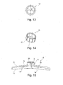
- the figure 15 schematically represents, in section, an analysis device 5 according to the invention, comprising a cover 6 fixed to a distribution device 1 by means of mounting pins 15 of the cover 6 snapped into corresponding housings 18 of the device of distribution 1.
- the distribution device 1 may comprise a peripheral rib 22 extending along the radially outer ends of the cuvettes 3.
- the cuvettes 3 may also be delimited by longitudinal ribs 23 parallel to each other, as can be seen in FIG. figure 9 .
- the cover 6 may comprise on its inner face protruding reliefs 19, for example pins, for example eight in number, intended to help maintain the test strips in the bowls 3, as can be seen on the figure 6 .
- the Figures 7 and 8 represent, respectively in plan view and in section, the cover 6 of the analysis device 5 of the Figures 5 and 6 .
- the cover 6 has identifiers 17, for example in the form of numbers, making it possible to identify the different cuvettes 3.
- the cover 6 may comprise observation windows 16 making it possible to observe the samples analyzed. in the cuvettes 3.
- the cover 6 can be translucent or opaque outside the observation windows 16, thanks to a frosted surface appearance, the observation windows 16 being polished to be at least partially transparent.
- the opening 8 may have an internal diameter D of between 10 and 20 mm, for example equal to 15 mm.
- the height H of the cover 6 may be between 15 and 30 mm, for example equal to 22 mm.
- the diameter L of the cover 6 may be between 100 and 120 mm, for example equal to 110 mm.
- the Figures 9 and 10 represent, respectively in plan view and in section, the distribution device 1 of the Figures 5 and 6 .
- the distribution device 1 comprises eight cuvettes 3 arranged radially around the central duct 2, being angularly spaced between them for example at an angle of 45 °.
- the interior of the chimney 2 communicates with each bowl 3 via passages 20 arranged regularly around the axis of the device, in the form for example of vertical slots.
- the internal volume of the central stack 2 is sufficient to accommodate the volume of sample introduced into the device, for example 0.5 mL or 1 mL.
- the width of the slots 20 is for example between 1 and 3 mm.
- the internal diameter d of the chimney 2 is for example between 5 and 15 mm, for example equal to 10 mm.
- central chimney may be preferable to the use of a dome for some kinds of samples, facilitating a uniform distribution in the bowls.
- each bowl 3 may be greater than 2 °, better 4 °, being for example equal to 5 °.
- the Figures 11 and 12 represent, respectively in plan view and in section, the analysis device 5 of the Figures 5 and 6 .
- the distribution device 1 is shown in dashed lines.
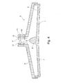
- the Figures 13 and 14 represent, respectively with a view from above and in perspective, the ring 13 making it possible to hold the closure element or elements in position 9.
- the ring 13 may have an internal diameter D 'of between 10 and 20 mm, for example equal to 14 mm.
- the ring 13 may further comprise splines 21, distributed regularly around the ring 13, to allow a retention of the ring 13 in the central opening 8 of the cover 6 by a force assembly.
- the user can place the strips carrying the reagents in the cuvettes then assemble the cover and the distribution device and introduce the sample through the closure system. An eventual color reaction of the strips can be observed through the windows, after the sample has flowed by gravity into the cuvettes.
- This flow is non-capillary in an embodiment of the invention, but the strips may optionally absorb the sample by capillarity.
Abstract
Description
La présente invention concerne un dispositif d'analyse, notamment pour la répartition d'un échantillon biologique. Le dispositif d'analyse selon l'invention est plus particulièrement adapté à la répartition d'un échantillon biologique dans des cuvettes utilisables pour des réactions immunologiques.The present invention relates to an analysis device, in particular for the distribution of a biological sample. The analysis device according to the invention is more particularly adapted to the distribution of a biological sample in cuvettes usable for immunological reactions.
Un grand nombre d'analyses biologiques quantitatives, semi-qualitatives ou qualitatives sont des analyses utilisant les réactions antigènes/anticorps. Ce type d'analyses est notamment utilisé pour mettre en évidence la présence d'anticorps, spécifiques d'un pathogène, dans le sang d'un patient. Ces techniques immunologiques sont couramment effectuées dans des récipients adaptés. Par exemple, la technique du western-blot consistant notamment à incuber des antigènes, répartis à la surface d'une bandelette de nitrocellulose, avec les anticorps contenus dans le sang d'un patient est réalisée dans des cuvettes en forme de tranchées. Une autre technique, l'ELISA (pour Enzyme-linked immunosorbent assay) est couramment réalisée dans des plaques comprenant une série de puits dans lesquels sont mis en contact l'antigène et l'anticorps.A large number of quantitative, semi-qualitative or qualitative bioassays are analyzes using antigen / antibody reactions. This type of analysis is used in particular to highlight the presence of antibodies specific for a pathogen in the blood of a patient. These immunological techniques are commonly performed in suitable containers. For example, the Western blot technique consisting in particular of incubating antigens, distributed on the surface of a nitrocellulose strip, with the antibodies contained in the blood of a patient is carried out in trench-shaped bowls. Another technique, ELISA (for Enzyme-linked immunosorbent assay ) is commonly performed in plates comprising a series of wells in which the antigen and the antibody are brought into contact.
Toutes ces techniques nécessitent une étape préliminaire consistant à répartir l'échantillon à analyser dans les différents récipients dans lesquels l'analyse va avoir lieu. Cette étape est particulièrement problématique puisque l'échantillon à analyser est souvent un échantillon biologique contenant des pathogènes (e.g. virus, bactéries). Cette étape de répartition est donc l'étape la plus dangereuse pour le manipulateur. Par ailleurs, lorsque cette répartition est effectuée à l'air libre, il existe un risque de contaminer les récipients contigus et ainsi fausser la validité des résultats.All these techniques require a preliminary step of distributing the sample to be analyzed in the different containers in which the analysis will take place. This step is particularly problematic since the sample to be analyzed is often a biological sample containing pathogens (e.g. viruses, bacteria). This distribution step is therefore the most dangerous step for the manipulator. In addition, when this distribution is carried out in the open air, there is a risk of contaminating the contiguous containers and thus distort the validity of the results.
On connaît déjà de l'art antérieur des dispositifs de répartition d'un liquide.Already known from the prior art devices for distributing a liquid.
La demande
La demande
La demande
Le brevet
La demande
Il existe un besoin pour de nouveaux dispositifs permettant de réaliser des analyses, et notamment des analyses biologiques, tout en diminuant les risques de contamination inter-analyses et les risques de perte de produit à l'extérieur des dispositifs et en préservant également la sécurité du manipulateur.There is a need for new devices to carry out analyzes, including biological analyzes, while reducing the risks of cross-analysis contamination and the risk of product loss outside the devices and also preserving the safety of the device. manipulator.
La présente invention propose de résoudre les problèmes décrits précédemment en fournissant notamment un dispositif d'analyse :
- assurant la sécurité de manipulation pour l'opérateur,
- empêchant tout risque de propagation de l'échantillon biologique infectieux dans l'environnement de travail,
- assurant le confort de lecture et la rapidité d'obtention des résultats,
- facilitant l'utilisation,
- ayant un coût réduit.
- guaranteeing safe handling for the operator,
- preventing any risk of propagation of the infectious biological sample in the working environment,
- ensuring reading comfort and quick results,
- facilitating the use,
- having a reduced cost.
Ainsi, la présente invention a pour objet, selon l'un de ses aspects, un dispositif d'analyse selon la revendication 1 et pouvant présenter l'une quelconque des caractéristiques facultatives faisant l'objet des revendications 2 à 15.Thus, according to one of its aspects, the subject of the present invention is an analysis device according to
La présente invention a ainsi pour objet, selon un premier de ses aspects, un dispositif d'analyse comportant :
- une pluralité de cuvettes,
- une ouverture d'introduction d'un échantillon liquide, munie d'un système d'obturation à travers lequel l'échantillon peut être introduit,
- un moyen de répartition de l'échantillon dans les cuvettes.
- a plurality of cuvettes,
- an opening for introducing a liquid sample, provided with a closure system through which the sample can be introduced,
- means for distributing the sample in the cuvettes.
Le système d'obturation permet de diminuer le risque de projection de liquide lors du retrait de l'outil introducteur, par exemple pipette, seringue ou canule, ayant servi à l'introduction de l'échantillon dans le dispositif, et permet de diminuer également le risque de perte rapide de liquide en cas de retournement accidentel du dispositif. De préférence, l'outil introducteur est une pipette. La quantité d'échantillon introduit est par exemple comprise entre 0,5 mL et 1 mL ; il peut s'agir de sang, salive ou de sérum.The closure system makes it possible to reduce the risk of splashing liquid during the withdrawal of the introducer tool, for example a pipette, syringe or cannula, which was used to introduce the sample into the device, and also makes it possible to reduce the risk of rapid loss of liquid in case of accidental rollover of the device. Preferably, the introducer tool is a pipette. The quantity of sample introduced is for example between 0.5 mL and 1 mL; it can be blood, saliva or serum.
Dans l'invention, selon ce premier aspect, l'échantillon peut être introduit à travers le système d'obturation, c'est-à-dire que celui-ci est présent dans le dispositif quand l'introduction de l'échantillon a lieu. Le système d'obturation est ainsi agencé pour à la fois réaliser la fonction d'obturation quand l'outil d'introduction est absent et permettre l'introduction du liquide quand l'outil introducteur délivre l'échantillon au dispositif.In the invention, according to this first aspect, the sample can be introduced through the closure system, that is to say that it is present in the device when the introduction of the sample takes place. . The shutter system is thus arranged to both perform the shutter function when the introduction tool is absent and allow the introduction of the liquid when the introducer tool delivers the sample to the device.
Le système d'obturation n'a pas à réaliser une obturation hermétique. Une obturation suffisante est obtenue quand les risques de projection et de perte rapide sont diminués. En particulier, il peut être avantageux que le dispositif satisfasse au test suivant : on remplit le dispositif avec 1 mL d'eau, on le retourne et l'on constate l'absence d'écoulement hors du dispositif d'analyse pendant au moins 10 s.The shutter system does not have to perform an airtight shutter. Sufficient closure is obtained when the risks of projection and rapid loss are reduced. In particular, it may be advantageous for the device to satisfy the following test: the device is filled with 1 ml of water, it is turned over and there is no flow out of the analysis device for at least 10 minutes. s.
Le système d'obturation peut être amovible ou non. Un montage amovible peut permettre un remplacement après utilisation. De préférence, le dispositif d'analyse est à usage unique.The shutter system may be removable or not. Removable mounting may allow replacement after use. Preferably, the analysis device is for single use.
Le système d'obturation peut être à mémoire de forme, c'est-à-dire qu'il reprend sa forme initiale après départ de l'outil introducteur.The shutter system may be shape memory, that is to say, it returns to its original shape after departure of the introducer tool.
Le système d'obturation peut être élastiquement déformable, afin de s'ouvrir pour permettre son franchissement par le bout de l'outil introducteur lorsque l'échantillon est délivré et se refermer ensuite automatiquement au départ de l'outil introducteur.The closure system can be elastically deformable, to open to allow its passage through the end of the introducer tool when the sample is delivered and then close automatically from the introducer tool.
Il peut être particulièrement avantageux que le système d'obturation soit à double étage, car l'étage inférieur peut jouer le rôle d'un essoreur de l'outil d'introduction lors de son retrait, ce qui diminue le risque de projection de liquide au départ de l'outil d'introduction.It may be particularly advantageous for the closure system to be double-decked, since the lower stage can act as a wiper of the insertion tool when it is withdrawn, which reduces the risk of liquid splashing. from the introductory tool.
Le terme « cuvette » doit se comprendre largement comme englobant toute cavité de toute forme propre à recevoir une fraction de l'échantillon. Le fond de la cuvette peut être plan ou non. Dans le cadre de la présente invention, le terme « cuvette » peut ainsi faire référence à une enceinte, préférentiellement à une enceinte dont la face supérieure comprend une ouverture sur tout ou partie de sa surface. Selon un mode de réalisation préféré de l'invention, la cuvette est un puits ou une tranchée. Des formes de puits ou de tranchée sont bien connues de l'homme du métier. Ils peuvent avoir la taille ou le format de puits utilisés habituellement pour la réalisation de test ELISA, ou des tranchées utilisées pour la réalisation de Western-blot ou des bandelettes d' immunochromatographie.The term "cuvette" should be broadly understood to include any cavity of any shape suitable for receiving a fraction of the sample. The bottom of the bowl may be flat or not. In the context of the present invention, the term "cuvette" can thus refer to an enclosure, preferably to an enclosure whose upper face comprises an opening on all or part of its surface. According to a preferred embodiment of the invention, the bowl is a well or a trench. Well or trench forms are well known to those skilled in the art. They may have the size or format of wells usually used for carrying out ELISA tests, or trenches used for the production of Western blot or immunochromatography strips.
Chaque cuvette peut recevoir une bandelette d'analyse, par exemple en nitrocellulose, laquelle porte au moins un réactif. Il peut s'agir d'un réactif donnant lieu à une réaction colorée en présence d'un agent pathogène. De préférence, chaque bandelette ne réagit qu'à un seul agent pathogène, afin de réduire le risque de réactions croisées dans une même cuvette. Chaque bandelette peut être initialement incolore.Each cuvette can receive an analysis strip, for example nitrocellulose, which carries at least one reagent. It may be a reagent giving rise to a color reaction in the presence of a pathogen. Preferably, each strip only reacts to a single pathogen, in order to reduce the risk of cross reactions in the same bowl. Each strip may initially be colorless.
Par « moyen de répartition » il faut comprendre tout moyen permettant de répartir l'échantillon dans les cuvettes et notamment toutes formes de surfaces permettant de guider l'écoulement entrant vers les cuvettes. La répartition se fait de préférence de façon égale entre les cuvettes mais pour certaines applications il est possible de chercher à privilégier le remplissage d'une cuvette par rapport à une autre.By "means of distribution" must be understood any means for distributing the sample in the cuvettes and including any form of surfaces to guide the flow to the basins. The distribution is preferably made equally between the cuvettes but for some applications it is possible to seek to favor the filling of a bowl relative to another.
Le moyen de répartition peut comporter un dispositif de répartition sous la forme d'une base sur laquelle sont formées les cuvettes, des canaux d'alimentation de ces cuvettes et tout déflecteur visant à diviser le flux initial en flux multiples d'alimentation des cuvettes, de préférence sous le seul effet de la gravité.The distribution means may comprise a distribution device in the form of a base on which are formed the cuvettes, feed channels of these cuvettes and any baffle for dividing the initial flow into multiple feed streams cuvettes, preferably under the sole effect of gravity.
Dans un exemple de mise en oeuvre de l'invention, les cuvettes sont disposées, quand le dispositif est observé en vue de dessus, autour de l'ouverture d'introduction. Cela peut permettre de réaliser un dispositif compact, stable et offrant une bonne visibilité.In an exemplary implementation of the invention, the cuvettes are arranged, when the device is observed in plan view, around the introduction opening. This can achieve a compact device, stable and with good visibility.
Dans un exemple de mise en oeuvre de l'invention, le dispositif d'analyse comporte un dispositif de répartition comprenant un dôme dont la base communique avec au moins une cuvette disposée radialement par rapport au dôme.In an exemplary implementation of the invention, the analysis device comprises a distribution device comprising a dome whose base communicates with at least one bowl disposed radially relative to the dome.
L'invention a donc aussi pour objet, selon un autre de ses aspects, un dispositif de répartition comprenant un dôme dont la base communique avec au moins une cuvette disposée radialement par rapport audit dôme, ainsi qu'un dispositif d'analyse comportant un tel dispositif de répartition.The invention therefore also relates, in another of its aspects, to a distribution device comprising a dome whose base communicates with at least one bowl disposed radially relative to said dome, as well as an analysis device comprising such a distribution device.
Le sommet du dôme, dans un exemple de dispositif de répartition, peut être utilisé comme une surface de réception sur laquelle le manipulateur peut déposer l'échantillon à répartir. Sous l'effet de la gravité, l'échantillon va s'écouler à la surface du dôme et se répartir dans les différentes cuvettes. Le dispositif de répartition peut ainsi permettre de répartir l'échantillon dans plusieurs cuvettes avec un minimum de manipulation.The top of the dome, in an exemplary distribution device, can be used as a receiving surface on which the manipulator can deposit the sample to be distributed. Under the effect of gravity, the sample will flow to the surface of the dome and distribute itself in the different cuvettes. The distribution device can thus allow to distribute the sample in several cuvettes with a minimum of manipulation.
Dans le cadre de la présente invention, le terme « communique » ci-dessus signifie que la face de la cuvette, contigüe au dôme, comprend une ouverture, sur tout ou partie de sa surface, permettant le passage d'un liquide de la base du dôme vers la cuvette.In the context of the present invention, the term "communicates" above means that the face of the bowl, contiguous to the dome, comprises an opening, over all or part of its surface, allowing the passage of a liquid from the base. from the dome to the bowl.
Selon un mode de réalisation préféré de l'invention, le dôme présente une base circulaire. Selon un mode de réalisation encore plus préféré, le dôme présente une hauteur supérieure au diamètre de sa base. Selon un mode de réalisation préféré de l'invention, le dôme a une forme symétrique de symétrie axiale ou de révolution, par exemple conique ou une forme d'ogive.According to a preferred embodiment of the invention, the dome has a circular base. According to an even more preferred embodiment, the dome has a height greater than the diameter of its base. According to a preferred embodiment of the invention, the dome has a symmetrical shape of axial symmetry or of revolution, for example conical or an ogival shape.
Le dispositif de répartition peut comporter une rigole disposée en périphérie de la base du dôme et mettant en communication les différentes cuvettes et la base du dôme.The distribution device may comprise a channel disposed at the periphery of the base of the dome and placing in communication the different bowls and the base of the dome.
Le système d'obturation peut comporter un ou plusieurs éléments d'obturation, qui peuvent être identiques ou non, de préférence deux éléments d'obturation situés à des hauteurs différentes afin de réaliser un système d'obturation à deux étages avec les avantages mentionnés ci-dessus.The shutter system may comprise one or more shutter elements, which may or may not be identical, preferably two shutter elements located at different heights in order to achieve a two-stage shutter system with the advantages mentioned herein. -above.
Le ou chaque élément d'obturation peut comporter un matériau élastomère, par exemple du silicone. L'élément d'obturation peut se présenter sous la forme d'une membrane, par exemple en forme de feuille, notamment de rondelle.The or each closure member may comprise an elastomeric material, for example silicone. The closure member may be in the form of a membrane, for example in the form of a sheet, in particular a washer.
Le ou chaque élément d'obturation peut comporter une découpe, notamment sous la forme de fente. La découpe peut être obtenue par moulage ou par un traitement post-moulage, par exemple de découpe au laser ou à l'aide d'une lame ou de tout autre outil de découpe.The or each shutter member may comprise a cutout, in particular in the form of a slot. The cutting can be obtained by molding or by post-molding treatment, for example by laser cutting or by means of a blade or other cutting tool.
La découpe peut être une fente à bords jointifs au repos. La longueur de la fente fait par exemple entre 5 et 15 mm. La découpe peut notamment permettre l'accès d'un embout de pipette ou d'une aiguille sous le système d'obturation afin de déposer un échantillon biologique. L'embout ou l'aiguille est introduit à travers les fentes. L'épaisseur d'un élément d'obturation est par exemple comprise entre 0,2 et 0,5 mm, notamment dans le cas d'une membrane en silicone.The cutout may be a slot with contiguous edges at rest. The length of the slot is for example between 5 and 15 mm. The cutout may in particular allow access of a pipette tip or a needle under the closure system to deposit a biological sample. The tip or needle is introduced through the slots. The thickness of a closure element is for example between 0.2 and 0.5 mm, especially in the case of a silicone membrane.
Le dispositif d'analyse peut comporter un capot qui est assemblé avec le dispositif de répartition, le capot définissant l'ouverture d'introduction. Le capot peut présenter un col dans lequel est disposé le système d'obturation, et dont l'extrémité supérieure définit l'ouverture d'introduction.The analysis device may comprise a cover which is assembled with the distribution device, the cover defining the insertion opening. The cover may have a neck in which the closure system is arranged, and whose upper end defines the insertion opening.
Les deux éléments d'obturation peuvent être espacés axialement l'un de l'autre d'une distance comprise entre 0,5 et 1,5 mm. Les deux éléments d'obturation sont avantageusement parallèles entre eux, disposés l'un au dessus de l'autre.The two closure elements may be spaced axially from each other by a distance of between 0.5 and 1.5 mm. The two sealing elements are advantageously parallel to each other, arranged one above the other.
Les deux éléments d'obturation peuvent être réalisés en un même matériau élastomère ou des matériaux élastomères différents.The two sealing elements may be made of the same elastomer material or different elastomeric materials.
Les deux éléments d'obturation peuvent comporter chacun une découpe, notamment sous la forme d'une fente. Les deux découpes peuvent être ou non au moins partiellement superposées l'une à l'autre.The two shutter elements may each include a cutout, in particular in the form of a slot. The two cuts may or may not be at least partially superimposed on one another.
Avantageusement, les découpes forment entre elles un angle sensiblement égal à 90°, se coupant par exemple sensiblement en leur milieu quand le dispositif est observé en vue de dessus. Les découpes peuvent ne pas être dans le même plan vertical, notamment afin d'assurer une meilleure étanchéité du dispositif d'analyse.Advantageously, the cuts form between them an angle substantially equal to 90 °, intersecting for example substantially in their middle when the device is observed in top view. The cutouts may not be in the same vertical plane, in particular in order to ensure better sealing of the analysis device.
Le dispositif d'analyse peut comporter une bague permettant de maintenir en place le ou les éléments d'obturation dans le col du capot. La bague peut présenter un diamètre extérieur suffisant pour permettre son maintien par frottement à l'intérieur du col. La bague est de préférence réalisée dans une matière plastique rigide.The analysis device may comprise a ring for holding in place the closure element or elements in the neck of the cover. The ring may have an outside diameter sufficient to allow its maintenance by friction inside the neck. The ring is preferably made of a rigid plastic material.
La bague peut être cannelée sur sa surface extérieure, notamment avec des stries réparties régulièrement à la périphérie de la bague, afin de permettre un maintien de la bague dans l'ouverture centrale du capot par un assemblage en force.The ring may be grooved on its outer surface, in particular with ridges evenly distributed around the periphery of the ring, in order to allow the ring to be held in the central opening of the cap by a force assembly.
La surface du dispositif de répartition sur laquelle s'écoule l'échantillon après son introduction peut être inclinée du centre vers la périphérie pour permettre une meilleure dispersion du liquide vers les cuvettes. En particulier, les cuvettes peuvent présenter une pente s'étendant de haut en bas, de la base du dôme ou de la cheminée centrale vers l'extrémité radialement extérieure des cuvettes.The surface of the distribution device on which the sample flows after its introduction can be inclined from the center to the periphery to allow better dispersion of the liquid to the cuvettes. In particular, the cuvettes may have a slope extending from top to bottom, from the base of the dome or the central chimney to the radially outer end of the cuvettes.
Le dispositif d'analyse peut comporter au moins deux cuvettes, mieux trois, encore mieux quatre cuvettes, par exemple entre 2 et 10 cuvettes.The analysis device may comprise at least two cuvettes, better three, even better four cuvettes, for example between 2 and 10 cuvettes.
Le capot peut comporter sur sa face intérieure au moins un premier relief de montage, destiné notamment à permettre la fixation du capot sur le dispositif de répartition. Le dispositif de répartition peut comporter au moins un deuxième relief complémentaire, les deux reliefs étant par exemple agencés pour s'encliqueter ou coopérer à force l'un dans l'autre. Le premier relief est par un exemple un logement défini dans un plot et le deuxième un picot ou inversement. Le capot peut comporter une pluralité de premiers reliefs et le dispositif de répartition une pluralité de deuxièmes reliefs correspondants, ces premiers et deuxièmes reliefs étant situés entre les cuvettes lorsque le dispositif d'analyse est observé du dessus.The cover may comprise on its inner face at least a first mounting relief, intended in particular to allow the fixing of the cover on the device of division. The distribution device may comprise at least one second complementary relief, the two reliefs being for example arranged to snap or cooperate by force one in the other. The first relief is for example a housing defined in a stud and the second a pin or vice versa. The cover may comprise a plurality of first reliefs and the distribution device a plurality of corresponding second reliefs, these first and second reliefs being located between the cuvettes when the analysis device is observed from above.
De préférence, la fixation du capot sur le dispositif de répartition est irréversible, c'est-à-dire qu'il est impossible pour l'utilisateur sans outil de séparer le capot du dispositif de répartition.Preferably, the fixing of the cover on the distribution device is irreversible, that is to say that it is impossible for the user without tools to separate the cover of the distribution device.
Le dispositif de répartition peut comporter une nervure périphérique s'étendant le long des extrémités radialement extérieures des cuvettes, et de préférence entre les cuvettes. Les cuvettes peuvent en outre être délimitées par des nervures longitudinales, notamment parallèles entre elles.The distribution device may comprise a peripheral rib extending along the radially outer ends of the cuvettes, and preferably between the cuvettes. The bowls may also be delimited by longitudinal ribs, in particular parallel to each other.
Le capot peut comporter sur sa face intérieure au moins un relief en saillie, par exemple un picot, destiné à aider au maintien d'une bandelette d'analyse dans une cuvette, notamment lorsque celle-ci présent un fond en pente.The cover may comprise on its inner face at least one raised projection, for example a pin, intended to help maintain an analysis strip in a bowl, especially when it has a sloping bottom.
Le dispositif, et notamment le capot, peut comporter au moins un identifiant, par exemple sous la forme d'un chiffre ou d'un nombre, permettant de repérer une cuvette. En particulier, le capot peut comporter un identifiant associé à chaque cuvette pour permettre son identification. L'identifiant peut être venu de moulage avec le capot.The device, and in particular the hood, may comprise at least one identifier, for example in the form of a number or a number, for identifying a bowl. In particular, the hood may include an identifier associated with each bowl to allow its identification. The identifier may have come from molding with the hood.
En outre, le capot peut comporter au moins une fenêtre d'observation permettant d'observer un échantillon contenu dans une cuvette. En particulier, le capot peut comporter une fenêtre d'observation associée à chaque cuvette. Le capot peut être translucide sans être transparent et les fenêtres d'observation peuvent correspondre à des zones polies du capot, l'aspect de surface les rendant ainsi au moins partiellement transparentes, ce qui facilite l'observation à travers elles du contenu des cuvettes.In addition, the hood may include at least one observation window for observing a sample contained in a bowl. In particular, the hood may include an observation window associated with each bowl. The cover can be translucent without being transparent and the viewing windows can correspond to polished areas of the cover, the surface appearance thus rendering them at least partially transparent, which facilitates the observation through them of the content of the cuvettes.
Le dispositif d'analyse peut être proposé à l'état monté avec plusieurs bandelettes d'analyse déjà en place. En variante, le dispositif d'analyse est proposé avec le capot et le dispositif de répartition à l'état séparé, indépendamment ou non de la fourniture de bandelettes. L'utilisateur place les bandelettes de son choix dans les cuvettes et assemble le capot avec le dispositif de répartition.The analysis device can be proposed in the assembled state with several analysis strips already in place. Alternatively, the analysis device is provided with the cover and the distribution device in the separated state, regardless of whether or not the supply of strips. The user places the strips of his choice in the cuvettes and assembles the hood with the distribution device.
D'autres avantages et caractéristiques ressortiront mieux de la description qui va suivre de variantes non limitatives d'exécution de l'invention et à l'examen des figures du dessin annexé, schématiques et partielles, sur lequel :
- la
figure 1 est une vue du dessus d'un mode de réalisation d'un dispositif de répartition d'un dispositif d'analyse selon l'invention, - la
figure 2 est une vue en coupe verticale partielle du dispositif d'analyse selon le mode de réalisation de lafigure 1 , - la
figure 3 est une vue de dessus du dispositif d'analyse de lafigure 2 , - la
figure 4 , est une vue en coupe verticale d'un autre mode de réalisation d'un dispositif d'analyse selon l'invention, - les
figures 5 sont des vues éclatées en perspective d'un autre mode de réalisation d'un dispositif d'analyse selon l'invention,et 6 - la
figure 7 est une vue du dessus du capot du dispositif d'analyse desfigures 5 ,et 6 - la
figure 8 est une vue en coupe selon VII-VII de lafigure 7 , - la
figure 9 est une vue du dessus du dispositif de répartition desfigures 5 ,et 6 - la
figure 10 est une vue en coupe selon IX-IX de lafigure 9 , - la
figure 11 est une vue du dessus du dispositif de répartition desfigures 5 ,et 6 - la
figure 12 est une vue en coupe selon XI-XI de lafigure 11 , - la
figure 13 est une vue du dessus de la bague du dispositif d'analyse desfigures 5 ,et 6 - la
figure 14 est une vue en perspective de la bague de lafigure 13 , et - la
figure 15 est une vue en coupe du dispositif d'analyse desfigures 5 représentant la fixation par puits de montage.et 6
- the
figure 1 is a view from above of an embodiment of a distribution device of an analysis device according to the invention, - the
figure 2 is a partial vertical sectional view of the analysis device according to the embodiment of thefigure 1 , - the
figure 3 is a top view of the analysis device of thefigure 2 , - the
figure 4 , is a vertical sectional view of another embodiment of an analysis device according to the invention, - the
Figures 5 and 6 are exploded perspective views of another embodiment of an analysis device according to the invention, - the
figure 7 is a view from above of the hood of the device for analyzingFigures 5 and 6 , - the
figure 8 is a sectional view along VII-VII of thefigure 7 , - the
figure 9 is a view from above of the distribution device ofFigures 5 and 6 , - the
figure 10 is a sectional view along IX-IX of thefigure 9 , - the
figure 11 is a view from above of the distribution device ofFigures 5 and 6 , - the
figure 12 is a sectional view according to XI-XI of thefigure 11 , - the
figure 13 is a top view of the ring of the device for analyzing theFigures 5 and 6 , - the
figure 14 is a perspective view of the ring of thefigure 13 , and - the
figure 15 is a sectional view of the device for analyzing theFigures 5 and 6 representing the fixing by mounting well.
Les différentes cotes présentes sur ces figures sont données à titre purement indicatif.The different dimensions present in these figures are given for information only.
En référence à la
Le dispositif de répartition 1 peut être constitué en tout ou partie d'une matière choisie dans le groupe comprenant le polystyrène, le polypropylène, le polycarbonate et le polystyrène téréphtalate (PET). Avantageusement, le dispositif de répartition selon l'invention est constitué d'une seule pièce et de manière encore plus avantageuse est réalisé en plastique moulé, injecté ou thermoformé.The
En référence à la
De la sorte, l'échantillon introduit est enclos dans un espace délimité par le capot 6 et le dispositif de répartition 1.In this way, the introduced sample is enclosed in a space delimited by the
Le capot 6 comprend une ouverture centrale 8 placée au dessus du dôme 2. Cette ouverture centrale 8 permet l'accès au dispositif de répartition 1, elle peut permettre notamment l'accès d'un embout de pipette ou d'une aiguille afin de déposer un échantillon biologique à la pointe du dôme 2.The
L'ouverture centrale 8 est obturée par un système d'obturation comprenant au moins un élément d'obturation 9. L'élément d'obturation 9 peut par exemple comporter une membrane de silicone. L'élément d'obturation 9 comprend avantageusement une découpe 10, notamment sous forme de fente. L'élément d'obturation 9 permet d'éviter que des produits présents à l'intérieur du dispositif d'analyse 5 s'en échappent, tout en préservant l'accès au dôme 2. Cet accès peut se faire, notamment, en transperçant l'élément d'obturation 9 (e.g. via une aiguille) ou en faisant passer un embout de pipette par la découpe 10.The
Afin d'améliorer la sécurisation du dispositif d'analyse 5 selon l'invention, l'ouverture 8 peut être avantageusement obturée par deux éléments d'obturation 9, en particulier des feuilles de silicone parallèles, ceux-ci pouvant comprendre avantageusement chacun une découpe 10. De façon préférée les découpes 10 ne sont pas placées dans le même plan vertical, afin d'assurer une meilleure-étanchéité du dispositif d'analyse 5.In order to improve the security of the
La face inférieure 7 du dispositif de répartition 1 constituant la face inférieure du dispositif d'analyse 5 est avantageusement opaque, en tout ou partie, afin de faciliter la lecture de l'analyse. Dans le même but, le capot 6 constituant la face supérieure du dispositif d'analyse 5 sera avantageusement en tout ou partie transparente (voir
Le capot 6 définissant la partie supérieure du dispositif d'analyse 5 peut être constitué en tout ou partie d'une matière choisie dans le groupe comprenant le polystyrène, le polypropylène, le polycarbonate et le polystyrène téréphtalate (PET). Avantageusement, le capot 6 est constitué d'une seule pièce et de manière encore plus avantageuse est réalisé en plastique moulé, injecté ou thermoformé.The
La
Selon ce mode de réalisation préféré, les cuvettes 3 présentent une pente s'étendant de haut en bas, de la base du dôme 2 vers l'extrémité extérieure de la cuvette 3.According to this preferred embodiment, the
Avantageusement, le capot 6 est marqué au niveau de chaque emplacement de cuvette 3 par une numérotation particulière, permettant l'identification de chaque cuvette 3.Advantageously, the
Les
Le dispositif d'analyse 5 comporte un capot 6 comportant un col 11 définissant une ouverture centrale 8 et un dispositif de répartition 1 qui comporte une cheminée centrale 2 et différentes cuvettes 3.The
Le dispositif d'analyse 5 comporte en outre une bague de retenue 13 permettant de maintenir en place deux éléments d'obturation 9 superposés l'un à l'autre, par pincement, à l'instar de ce qui a été précédemment décrit. Les éléments d'obturation 9 comportent chacun une découpe 10. Chaque découpe a la forme d'une fente rectiligne, et les deux découpes 10 forment avantageusement un angle de 90° entre elles, afin notamment d'assurer une meilleure étanchéité du dispositif d'analyse 5.The
Comme on peut le voir sur la
Comme on peut le voir sur la
La
Le dispositif de répartition 1 peut comporter une nervure périphérique 22 s'étendant le long des extrémités radialement extérieures des cuvettes 3. Les cuvettes 3 peuvent en outre être délimitées par des nervures longitudinales 23 parallèles entre elles, comme on peut le voir sur la
Le capot 6 peut comporter sur sa face intérieure des reliefs en saillie 19, par exemple des picots, par exemple au nombre de huit, destinés à aider au maintien des bandelettes d'analyse dans les cuvettes 3, comme on peut le voir sur la
Les
Sur la
L'ouverture 8 peut présenter un diamètre intérieur D compris entre 10 et 20 mm, par exemple égal à 15 mm. La hauteur H du capot 6 peut être comprise entre 15 et 30 mm, par exemple égale à 22 mm. Le diamètre L du capot 6 peut être compris entre 100 et 120 mm, par exemple égal à 110 mm.The
Les
Sur la
Le diamètre intérieur d de la cheminée 2 est par exemple compris entre 5 et 15 mm, par exemple égal à 10 mm.The internal diameter d of the
L'utilisation d'une cheminée centrale peut être préférable à l'utilisation d'un dôme pour certaines natures d'échantillons, facilitant une répartition uniforme dans les cuvettes.The use of a central chimney may be preferable to the use of a dome for some kinds of samples, facilitating a uniform distribution in the bowls.
L'angle d'inclinaison a de chaque cuvette 3 par rapport à l'horizontal, c'est-à-dire l'angle que fait la pente de chaque cuvette depuis la base de la cheminée 2 vers l'extrémité radialement extérieure de la cuvette 3, peut être supérieur à 2°, mieux 4°, étant par exemple égal à 5°.The angle of inclination α of each
Les
Sur la
Les
Pour utiliser le dispositif d'analyse, l'utilisateur peut placer les bandelettes portant les réactifs dans les cuvettes puis assembler le capot et le dispositif de répartition et introduire l'échantillon à travers le système d'obturation. Une réaction colorée éventuelle des bandelettes peut être observée à travers les fenêtres, après que l'échantillon se soit écoulé par gravité dans les cuvettes. Cet écoulement est non capillaire dans un exemple de mise en oeuvre de l'invention, mais les bandelettes peuvent éventuellement absorber par capillarité l'échantillon.To use the analysis device, the user can place the strips carrying the reagents in the cuvettes then assemble the cover and the distribution device and introduce the sample through the closure system. An eventual color reaction of the strips can be observed through the windows, after the sample has flowed by gravity into the cuvettes. This flow is non-capillary in an embodiment of the invention, but the strips may optionally absorb the sample by capillarity.
L'expression « comportant un » doit être comprise comme étant synonyme de « comportant au moins un », sauf si le contraire est spécifié.The expression "having one" shall be understood as being synonymous with "having at least one", unless the opposite is specified.
Claims (15)
Applications Claiming Priority (1)
| Application Number | Priority Date | Filing Date | Title |
|---|---|---|---|
| FR1000208A FR2955268B1 (en) | 2010-01-20 | 2010-01-20 | DEVICE FOR DISTRIBUTION, IN PARTICULAR FOR A BIOLOGICAL SAMPLE |
Publications (2)
| Publication Number | Publication Date |
|---|---|
| EP2347826A2 true EP2347826A2 (en) | 2011-07-27 |
| EP2347826A3 EP2347826A3 (en) | 2012-01-04 |
Family
ID=42562614
Family Applications (1)
| Application Number | Title | Priority Date | Filing Date |
|---|---|---|---|
| EP11151594A Withdrawn EP2347826A3 (en) | 2010-01-20 | 2011-01-20 | Distribution device, in particular for a biological sample |
Country Status (2)
| Country | Link |
|---|---|
| EP (1) | EP2347826A3 (en) |
| FR (1) | FR2955268B1 (en) |
Citations (5)
| Publication number | Priority date | Publication date | Assignee | Title |
|---|---|---|---|---|
| US4123173A (en) | 1976-06-09 | 1978-10-31 | Electro-Nucleonics, Inc. | Rotatable flexible cuvette arrays |
| FR2400700A1 (en) | 1977-08-18 | 1979-03-16 | Guigan Jean | CONDITIONING DEVICE FOR A LIQUID SAMPLE FOR ANALYSIS |
| EP0034049A1 (en) | 1980-02-06 | 1981-08-19 | EASTMAN KODAK COMPANY (a New Jersey corporation) | Test device for analysis of a plurality of analytes |
| EP0373863A2 (en) | 1988-12-12 | 1990-06-20 | Bayer Corporation | Analytical test device |
| US20040152206A1 (en) | 2002-01-31 | 2004-08-05 | Davis James O. | Universal sample collection and testing system |
Family Cites Families (8)
| Publication number | Priority date | Publication date | Assignee | Title |
|---|---|---|---|---|
| FR2424531A2 (en) * | 1978-04-28 | 1979-11-23 | Guigan Jean | Appts. for conditioning liq. samples for analysis - comprising calibrated peripheral cells for optical measurement filled completely from central receptacle by centrifugation |
| IN154925B (en) * | 1979-10-26 | 1984-12-22 | Guigan Jean | |
| US5789251A (en) * | 1994-06-16 | 1998-08-04 | Astle; Thomas W. | Multi-well bioassay tray with evaporation protection and method of use |
| DE19852835A1 (en) * | 1998-11-17 | 2000-05-18 | Stratec Biomedical Systems Ag | Sample holder |
| JP3990910B2 (en) * | 1999-07-16 | 2007-10-17 | アプレラ コーポレイション | High density electrophoresis device and method |
| WO2002000347A2 (en) * | 2000-06-28 | 2002-01-03 | 3M Innovative Properties Company | Sample processing devices, systems and methods |
| US7582472B2 (en) * | 2003-08-26 | 2009-09-01 | Smith Kenneth E | Apparatus and method for liquid sample testing |
| DE202008007941U1 (en) * | 2008-06-13 | 2008-10-16 | Becciolini, Jean-Jacques | Device for the detection of ingredients in a liquid, in particular in urine, and cap for covering the device |
-
2010
- 2010-01-20 FR FR1000208A patent/FR2955268B1/en active Active
-
2011
- 2011-01-20 EP EP11151594A patent/EP2347826A3/en not_active Withdrawn
Patent Citations (5)
| Publication number | Priority date | Publication date | Assignee | Title |
|---|---|---|---|---|
| US4123173A (en) | 1976-06-09 | 1978-10-31 | Electro-Nucleonics, Inc. | Rotatable flexible cuvette arrays |
| FR2400700A1 (en) | 1977-08-18 | 1979-03-16 | Guigan Jean | CONDITIONING DEVICE FOR A LIQUID SAMPLE FOR ANALYSIS |
| EP0034049A1 (en) | 1980-02-06 | 1981-08-19 | EASTMAN KODAK COMPANY (a New Jersey corporation) | Test device for analysis of a plurality of analytes |
| EP0373863A2 (en) | 1988-12-12 | 1990-06-20 | Bayer Corporation | Analytical test device |
| US20040152206A1 (en) | 2002-01-31 | 2004-08-05 | Davis James O. | Universal sample collection and testing system |
Also Published As
| Publication number | Publication date |
|---|---|
| FR2955268B1 (en) | 2019-06-28 |
| FR2955268A1 (en) | 2011-07-22 |
| EP2347826A3 (en) | 2012-01-04 |
Similar Documents
| Publication | Publication Date | Title |
|---|---|---|
| EP0678745B1 (en) | Method and apparatus for immunological analysis | |
| US6669908B2 (en) | Urine test device | |
| EP2378980B1 (en) | Device for sampling tissue from an animal | |
| FR2609334A1 (en) | IMMUNO-TEST OR DIAGNOSTIC DEVICE AND METHOD FOR MANUFACTURING SAME | |
| EP2068718B1 (en) | Device for sampling biological tissue for the identification of animals | |
| CH623415A5 (en) | ||
| US8992855B2 (en) | Low volume liquid specimen apportionment device | |
| JP2004516932A (en) | Centrifuge test device and centrifuge equipped with the test device | |
| KR102100840B1 (en) | Transport medium for preventing a specimen from being contaminated | |
| FR2969128A1 (en) | CAP FOR CLOSING A CONTAINER | |
| FR2882943A1 (en) | APPARATUS FOR PROCESSING BIOLOGICAL SAMPLES. | |
| EP0827427B1 (en) | Fluid testing and analysing device and method | |
| JP2017513691A (en) | Liquid sample filtration device | |
| KR101265066B1 (en) | Medium vessel for specimen transport and microorganism culturing | |
| WO2021250360A1 (en) | Device for holding tubes used for analysing samples by means of nucleic acid amplification techniques and method for using such a device | |
| WO2007068811A1 (en) | Housing for assaying a biological sample by immunochromatography | |
| EP2347826A2 (en) | Distribution device, in particular for a biological sample | |
| US20090209882A1 (en) | Integrated cap and sample applicator | |
| WO2011073359A2 (en) | Storage device for an animal tissue sample | |
| WO2017149234A1 (en) | Automatic analysing system for in vitro diagnostics | |
| EP3877741B1 (en) | Device for preparing at least one sample by coring a sample of material | |
| WO2014102501A1 (en) | Analysis bar including means for attaching a cone to said bar | |
| FR2934506A1 (en) | Liquid reagent product containing container for cartridge of analyzing assembly in analyzing apparatus, has closure plug whose bottom wall closes end of skirt, where wall has slot permitting passage of probe or needle of analyzing apparatus | |
| WO2022047273A1 (en) | Plural individual specimen collecting, transporting & analyzing device and method | |
| FR2790686A1 (en) | ANALYSIS CARD WHICH FILLING IS ASSOCIATED WITH AT LEAST ONE BUFFER VOLUME |
Legal Events
| Date | Code | Title | Description |
|---|---|---|---|
| PUAI | Public reference made under article 153(3) epc to a published international application that has entered the european phase |
Free format text: ORIGINAL CODE: 0009012 |
|
| 17P | Request for examination filed |
Effective date: 20110120 |
|
| AK | Designated contracting states |
Kind code of ref document: A2 Designated state(s): AL AT BE BG CH CY CZ DE DK EE ES FI FR GB GR HR HU IE IS IT LI LT LU LV MC MK MT NL NO PL PT RO RS SE SI SK SM TR |
|
| AX | Request for extension of the european patent |
Extension state: BA ME |
|
| PUAL | Search report despatched |
Free format text: ORIGINAL CODE: 0009013 |
|
| AK | Designated contracting states |
Kind code of ref document: A3 Designated state(s): AL AT BE BG CH CY CZ DE DK EE ES FI FR GB GR HR HU IE IS IT LI LT LU LV MC MK MT NL NO PL PT RO RS SE SI SK SM TR |
|
| AX | Request for extension of the european patent |
Extension state: BA ME |
|
| RIC1 | Information provided on ipc code assigned before grant |
Ipc: B01L 3/00 20060101AFI20111130BHEP Ipc: G01N 33/48 20060101ALI20111130BHEP Ipc: G01N 21/03 20060101ALI20111130BHEP |
|
| 17Q | First examination report despatched |
Effective date: 20120207 |
|
| STAA | Information on the status of an ep patent application or granted ep patent |
Free format text: STATUS: EXAMINATION IS IN PROGRESS |
|
| STAA | Information on the status of an ep patent application or granted ep patent |
Free format text: STATUS: THE APPLICATION IS DEEMED TO BE WITHDRAWN |
|
| 18D | Application deemed to be withdrawn |
Effective date: 20180801 |