EP2361790A1 - Tyre comprising an electronic element - Google Patents
Tyre comprising an electronic element Download PDFInfo
- Publication number
- EP2361790A1 EP2361790A1 EP11155436A EP11155436A EP2361790A1 EP 2361790 A1 EP2361790 A1 EP 2361790A1 EP 11155436 A EP11155436 A EP 11155436A EP 11155436 A EP11155436 A EP 11155436A EP 2361790 A1 EP2361790 A1 EP 2361790A1
- Authority
- EP
- European Patent Office
- Prior art keywords
- tire
- mass
- reinforcement
- rubber
- electronic member
- Prior art date
- Legal status (The legal status is an assumption and is not a legal conclusion. Google has not performed a legal analysis and makes no representation as to the accuracy of the status listed.)
- Granted
Links
- 230000002787 reinforcement Effects 0.000 claims abstract description 66
- 239000011324 bead Substances 0.000 claims abstract description 10
- 239000004753 textile Substances 0.000 claims abstract description 10
- 230000003014 reinforcing effect Effects 0.000 claims abstract description 4
- 239000011248 coating agent Substances 0.000 claims description 15
- 238000000576 coating method Methods 0.000 claims description 15
- 239000002184 metal Substances 0.000 claims description 6
- 150000001875 compounds Chemical class 0.000 claims description 2
- 238000004519 manufacturing process Methods 0.000 description 9
- 230000005540 biological transmission Effects 0.000 description 6
- 210000000056 organ Anatomy 0.000 description 4
- 239000000463 material Substances 0.000 description 2
- HUWSZNZAROKDRZ-RRLWZMAJSA-N (3r,4r)-3-azaniumyl-5-[[(2s,3r)-1-[(2s)-2,3-dicarboxypyrrolidin-1-yl]-3-methyl-1-oxopentan-2-yl]amino]-5-oxo-4-sulfanylpentane-1-sulfonate Chemical compound OS(=O)(=O)CC[C@@H](N)[C@@H](S)C(=O)N[C@@H]([C@H](C)CC)C(=O)N1CCC(C(O)=O)[C@H]1C(O)=O HUWSZNZAROKDRZ-RRLWZMAJSA-N 0.000 description 1
- 230000002238 attenuated effect Effects 0.000 description 1
- 238000003490 calendering Methods 0.000 description 1
- 239000000356 contaminant Substances 0.000 description 1
- 230000006355 external stress Effects 0.000 description 1
- 239000007769 metal material Substances 0.000 description 1
- 238000000034 method Methods 0.000 description 1
- 238000012986 modification Methods 0.000 description 1
- 230000004048 modification Effects 0.000 description 1
- 239000003921 oil Substances 0.000 description 1
- 230000001681 protective effect Effects 0.000 description 1
- 239000000565 sealant Substances 0.000 description 1
- 230000035939 shock Effects 0.000 description 1
- 238000004073 vulcanization Methods 0.000 description 1
- XLYOFNOQVPJJNP-UHFFFAOYSA-N water Substances O XLYOFNOQVPJJNP-UHFFFAOYSA-N 0.000 description 1
Images

Classifications
-
- B—PERFORMING OPERATIONS; TRANSPORTING
- B60—VEHICLES IN GENERAL
- B60C—VEHICLE TYRES; TYRE INFLATION; TYRE CHANGING; CONNECTING VALVES TO INFLATABLE ELASTIC BODIES IN GENERAL; DEVICES OR ARRANGEMENTS RELATED TO TYRES
- B60C23/00—Devices for measuring, signalling, controlling, or distributing tyre pressure or temperature, specially adapted for mounting on vehicles; Arrangement of tyre inflating devices on vehicles, e.g. of pumps or of tanks; Tyre cooling arrangements
- B60C23/02—Signalling devices actuated by tyre pressure
- B60C23/04—Signalling devices actuated by tyre pressure mounted on the wheel or tyre
- B60C23/0491—Constructional details of means for attaching the control device
- B60C23/0493—Constructional details of means for attaching the control device for attachment on the tyre
-
- G—PHYSICS
- G06—COMPUTING; CALCULATING OR COUNTING
- G06K—GRAPHICAL DATA READING; PRESENTATION OF DATA; RECORD CARRIERS; HANDLING RECORD CARRIERS
- G06K19/00—Record carriers for use with machines and with at least a part designed to carry digital markings
- G06K19/06—Record carriers for use with machines and with at least a part designed to carry digital markings characterised by the kind of the digital marking, e.g. shape, nature, code
- G06K19/067—Record carriers with conductive marks, printed circuits or semiconductor circuit elements, e.g. credit or identity cards also with resonating or responding marks without active components
- G06K19/07—Record carriers with conductive marks, printed circuits or semiconductor circuit elements, e.g. credit or identity cards also with resonating or responding marks without active components with integrated circuit chips
- G06K19/077—Constructional details, e.g. mounting of circuits in the carrier
- G06K19/07749—Constructional details, e.g. mounting of circuits in the carrier the record carrier being capable of non-contact communication, e.g. constructional details of the antenna of a non-contact smart card
- G06K19/07758—Constructional details, e.g. mounting of circuits in the carrier the record carrier being capable of non-contact communication, e.g. constructional details of the antenna of a non-contact smart card arrangements for adhering the record carrier to further objects or living beings, functioning as an identification tag
- G06K19/07764—Constructional details, e.g. mounting of circuits in the carrier the record carrier being capable of non-contact communication, e.g. constructional details of the antenna of a non-contact smart card arrangements for adhering the record carrier to further objects or living beings, functioning as an identification tag the adhering arrangement making the record carrier attachable to a tire
-
- H—ELECTRICITY
- H01—ELECTRIC ELEMENTS
- H01Q—ANTENNAS, i.e. RADIO AERIALS
- H01Q1/00—Details of, or arrangements associated with, antennas
- H01Q1/12—Supports; Mounting means
- H01Q1/22—Supports; Mounting means by structural association with other equipment or articles
- H01Q1/2208—Supports; Mounting means by structural association with other equipment or articles associated with components used in interrogation type services, i.e. in systems for information exchange between an interrogator/reader and a tag/transponder, e.g. in Radio Frequency Identification [RFID] systems
- H01Q1/2241—Supports; Mounting means by structural association with other equipment or articles associated with components used in interrogation type services, i.e. in systems for information exchange between an interrogator/reader and a tag/transponder, e.g. in Radio Frequency Identification [RFID] systems used in or for vehicle tyres
-
- H—ELECTRICITY
- H01—ELECTRIC ELEMENTS
- H01Q—ANTENNAS, i.e. RADIO AERIALS
- H01Q9/00—Electrically-short antennas having dimensions not more than twice the operating wavelength and consisting of conductive active radiating elements
- H01Q9/04—Resonant antennas
- H01Q9/16—Resonant antennas with feed intermediate between the extremities of the antenna, e.g. centre-fed dipole
-
- B—PERFORMING OPERATIONS; TRANSPORTING
- B29—WORKING OF PLASTICS; WORKING OF SUBSTANCES IN A PLASTIC STATE IN GENERAL
- B29D—PRODUCING PARTICULAR ARTICLES FROM PLASTICS OR FROM SUBSTANCES IN A PLASTIC STATE
- B29D30/00—Producing pneumatic or solid tyres or parts thereof
- B29D30/0061—Accessories, details or auxiliary operations not otherwise provided for
- B29D2030/0077—Directly attaching monitoring devices to tyres before or after vulcanization, e.g. microchips
-
- Y—GENERAL TAGGING OF NEW TECHNOLOGICAL DEVELOPMENTS; GENERAL TAGGING OF CROSS-SECTIONAL TECHNOLOGIES SPANNING OVER SEVERAL SECTIONS OF THE IPC; TECHNICAL SUBJECTS COVERED BY FORMER USPC CROSS-REFERENCE ART COLLECTIONS [XRACs] AND DIGESTS
- Y10—TECHNICAL SUBJECTS COVERED BY FORMER USPC
- Y10T—TECHNICAL SUBJECTS COVERED BY FORMER US CLASSIFICATION
- Y10T152/00—Resilient tires and wheels
- Y10T152/10—Tires, resilient
- Y10T152/10495—Pneumatic tire or inner tube
- Y10T152/10855—Characterized by the carcass, carcass material, or physical arrangement of the carcass materials
Definitions
- the present invention relates to a tire comprising an electronic member.
- a tire usually comprises a carcass ply provided with textile threads, unlike a tire for a heavy goods vehicle which generally comprises carcass ply threads made of metallic material.
- the electronic device comprises a passive radio frequency identification transponder provided with two dipole antennas.
- This type of transponder is generally designated by the acronym RFID.
- RFID RFID
- the tire described in EP 0 389 406 in particular illustrated in figure 2 of this document, comprises an annular rod, of revolution about an axis substantially coinciding with the axis of revolution of the tire, and a carcass reinforcement, generally toroidal shape coaxial with the rod, comprising a folded portion around the rod .
- the transponder is positioned in the mass of the tire so that it creates in the tire an interface of materials, namely the interface defined by the junction between at least a first mass of rubber and a second mass formed by the transponder.
- a portion of the transponder, in particular one of the antennas, extends in the volume between the folded portion of the carcass ply reinforcement and a portion of this carcass reinforcement axially opposite the folded portion.
- the object of the invention is in particular to optimize the position of an electronic element, such as a transponder, in the mass of the tire so as to optimize the endurance of the transponder as well as the transmission of the data stored in the transponder, this without modifying the main stages of manufacture of the tire or its architecture.
- the subject of the invention is an aircraft tire having the capacity to work at an inflation pressure greater than 12 bar, comprising a top, two flanks and two beads, a carcass reinforcement anchored in both beads and consisting of at least one ply of textile reinforcements, a crown reinforcement with radially from the inside to the outside a working block consisting of textile reinforcing plies and a protection block comprising reinforcements oriented substantially circumferentially and an electronic member of elongated general shape, and comprising a passive radio frequency identification transponder provided with two dipole antennas.
- This tire is characterized in that the reinforcements of the protection block of the crown reinforcement are corrugated metallic reinforcements and in that the electronic member is disposed in the tire structure under the crown, radially inwardly relative to the reinforcement carcass ply and oriented in a substantially axial direction.
- axially inner relative to the carcass ply reinforcement is meant that the member is closer to the tire surface in contact with the internal air than the carcass ply reinforcement.
- the orientation of the electronic member in a substantially axial direction has the advantage of allowing this electronic member to withstand without damage the conformation of the tire blank during its manufacture, that is to say the operation which consists, after having deposited on a manufacturing drum the first products, including the inner liner, the body, the carcass reinforcement and the rods, to give this cylindrical blank a toric shape.
- the tire comprising a mass of rubber, called inner rubber, delimited by an inner surface in contact with the air inside the tire, and an outer surface in contact with an adjacent mass of rubber, the electronic member is placed at interface between the inner liner and the adjacent gum mass.
- This position of the electronic member according to the invention makes it easy to set up the electronic member during the assembly of the materials of the green tire. And this is insensitive to the architectural variations on the outer side of the carcass reinforcement.
- the electronic member is also particularly well protected vis-à-vis external stresses such as tire shocks against an obstacle on the road or a pothole.
- the body Being placed inside the structure of the tire, the body is also protected from any type of contaminant that may be inside the internal cavity of the tire (water, oil, sealants ...) .
- this position allows a substantially improved endurance of the member relative to any position externally to the carcass reinforcement.
- the electronic member is disposed under the crown of the tire in the middle of the width of the crown.
- the transmission of the data by the electronic organ is quite satisfactory.
- the positioning in the middle of the width of the crown has the advantage of having the same reading distance of the member, whether one is on the left side or on the right side of the tire.
- the electronic member is wrapped with a mass of coating gum.
- the relative dielectric constant of the gum of the coating mass is lower than the relative dielectric constants of the inner liner and the adjacent gum mass.
- the transmission of data stored by the electronic member is improved.
- the higher the dielectric constant of a rubber body encasing the electronic member the more the electric signal received and emitted by the electronic member is attenuated.
- the dielectric constants of the inner gum and adjacent gum mass generally greater than 10 in the UHF range, the data transmission is greatly improved in the case where the relative dielectric constant of the gum of the coating mass is lower than the dielectric constants relative gums in the frequency domain used.
- the dielectric constant of the coating gum mass is less than 4 and preferably less than 3 in the UHF frequency range.
- the coating gum mass has a length in the limited axial direction exceeding the length of the electronic member only a few millimeters at each of its ends. By a few millimeters one understands of the order of three to five millimeters.
- the adjacent mass of rubber may be constituted by the carcass reinforcement.
- This adjacent mass of rubber can also be an additional mass of gum disposed between the inner liner and the carcass ply reinforcement of the tire.
- the presence of such additional mass of rubber is usual in aircraft tire architectures.
- the inner liner may also, according to a preferred embodiment, be constituted by the assembly of at least two masses of rubber.
- substantially circumferential orientation means an average orientation that does not deviate by more than five degrees from the circumferential direction Z.
- FIG. 10 a tire according to the invention designated by the general reference 10.
- the tire 10 is intended to be mounted on an aircraft wheel.
- the tire 10 comprises an apex S extended by two flanks F and two beads B. Only one flank and the apex are represented on the tire. figure 1 .
- the rods 16 are each embedded in a bead B.
- the two rods 16 are arranged symmetrically with respect to a median radial plane M of the tire (see FIG. Fig. 4 ).
- Each rod 16 is of revolution about a reference axis.
- This reference axis substantially parallel to the Y direction, is substantially coincident with an axis of revolution of the tire.
- the top S comprises a tread 20, provided with carvings 22, as well as a crown reinforcement 24.
- This frame 24 comprises a work block 26 and a protection block 28.
- the work block consists of several layers of textile reinforcements.
- the protection block 28 is preferably made of metal reinforcements placed with corrugations in the plane of the top to obtain the greatest possible efficiency. Each reinforcement retains a substantially circumferential mean orientation.
- a mass of rubber 36 extends radially from the top to the level of the rod 16 of the bead B defining an outer surface 37 of the sidewall F and the bead B.
- the tire 10 also comprises a sealed inner rubber body 40 as well as a carcass reinforcement 42.
- the interior rubber compound or inner rubber 40 is delimited by an internal surface 41 in contact with the air inside the tire, and a surface external contact with an adjacent mass of rubber.
- the adjacent gums may be the carcass ply reinforcement 42 or one or more additional gums arranged between the inner liner and the carcass ply.
- an additional mass of rubber 43 is an additional mass of rubber 43. This additional mass of rubber 43 extends from one bead to the other between the carcass reinforcement 42 and the waterproof rubber. 40.
- the carcass reinforcement in the example shown comprises one or more plies of textile reinforcements oriented substantially radially.
- the crown S of the tire 10 also comprises an electronic member 54 optionally coated with a mass of rubber 60.
- the electronic member 54 has a generally elongate shape in a substantially axial direction Y (parallel to the axis of rotation).
- the member 54 comprises a passive radio frequency identification (RFID) transponder 56 provided with two antennas 58 forming a dipole.
- RFID radio frequency identification
- the member 54 is disposed between the inner liner 40 and the carcass ply 42.
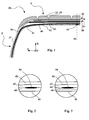
- figure 2 detail of the figure 1 , illustrates the position of the member 54 in the S-top.
- an additional rubber 43 Between the inner liner 40 and the carcass ply 42 is an additional rubber 43.
- the member is disposed at the interface between the additional rubber 43 and the inner liner 40 In the absence of this additional rubber 43, it is possible to arrange the member at the interface between the inner liner and the carcass reinforcement.
- the carcass ply reinforcement consists of one or more plies each comprising textile reinforcements of substantially radial orientation embedded between two layers of calendering gums. There is therefore no direct contact between the member and the reinforcements of the carcass ply reinforcement.
- the member may also be placed at the interface between the additional rubber 43 and the inner rubber 40, or at the interface between the carcass reinforcement and the additional rubber 43.
- the organ is placed in the middle of the top S, near the median plane M.
- the figure 3 similarly to the figure 2 a second embodiment of a tire according to the invention in which the inner liner 40 consists of the assembly of two masses of rubber, a first mass of rubber corresponding to the sealed inner rubber 40 and a second mass of rubber 44.
- the electronic member 54 is then placed at the interface between the first mass of additional rubber 43 and the second mass of additional rubber 44.
- the figure 4 very schematically shows a perspective view with partial detachments of the outer face of the tire 10.
- This figure shows the outer surface of the tread 20 of the tire 10 with a tread 22 comprising four circumferential grooves 19.
- the protection block 28 of the crown reinforcement comprises a sheet of metal reinforcements placed with corrugations while maintaining a circumferential mean orientation.
- the work block 26 composed of strips of textile reinforcements sliced with an angle of the order of ten degrees relative to the alternating circumferential direction of a layer of reinforcements to the next supplemented optionally reinforcements oriented substantially circumferentially.
- the electronic member 54 consists of a transponder with passive radio frequency identification (RFID) 56 provided with two antennas 58 forming a dipole. The assembly is oriented in the axial direction parallel to the rollbars reinforcements of the carcass ply reinforcement.
- RFID radio frequency identification
- the electronic member 54 is enveloped by two thin layers of coating rubber mass 55. These two layers extend axially beyond the antennas 58 by a distance of between 3 and 5 mm.
- the two layers 55 constitute the mass of coating gum 60 of the member 54.
- the axial orientation of the antennas 58 of the member 54 makes it possible to maintain excellent transmission of the signals even in the presence of the metal reinforcements of the protective block of the Mountain peak. Indeed, these metal reinforcements are oriented circumferentially. This axial orientation also allows good endurance of the body in the tire during its manufacture and during its service.
- the dielectric constant of the coating gum is lower than the dielectric constants of the inner and additional gums as well as the calenders of the carcass ply.
- an electronic member 54 in the structure of a tire during its manufacture is simple. After setting up the inner liner on a manufacturing drum, the body and coating body assembly is applied to a suitable place, then the additional rubber is applied, followed by the carcass ply, and the application of the liner is usually completed. set of gums and products necessary to constitute the rough outline of the tire. After vulcanization of this blank, a pneumatic or pneumatic envelope is obtained ready for use.
- the interface chosen to set up the electronic member may vary depending on the manufacturing techniques used. When a semi-finished assembly consisting of the inner liner and an adjacent liner is made, the interface between the liner and the adjacent liner is not available for placement of the liner during the manufacture of the tire. The member is then placed at the interface between this additional rubber and the carcass reinforcement of the tire. In the example of the figure 2 , the electronic member would then be placed at the interface between the additional rubber 43 and the carcass reinforcement 42. In the example of the figure 3 , the electronic member is then disposed at the interface between the additional rubber 44 and the additional rubber 43 radially inwardly relative to the carcass reinforcement of the tire.
Abstract
Description
La présente invention concerne un pneumatique comprenant un organe électronique.The present invention relates to a tire comprising an electronic member.
Elle s'applique en particulier, mais non exclusivement, à un pneumatique destiné à porter de lourdes charges et gonflé à très haute pression, supérieure à 12 bars, tel que par exemple un pneumatique d'avion.It applies in particular, but not exclusively, to a tire intended to carry heavy loads and inflated to a very high pressure, greater than 12 bar, such as, for example, an aircraft tire.
Un pneumatique, répondant aux critères ci-dessus comprend usuellement une nappe carcasse munie de fils textiles, ceci à la différence d'un pneumatique pour véhicule poids lourds qui comprend généralement des fils de nappe carcasse en matériau métallique.A tire, meeting the above criteria, usually comprises a carcass ply provided with textile threads, unlike a tire for a heavy goods vehicle which generally comprises carcass ply threads made of metallic material.
On définira les directions axiale, radiale et circonférentielle d'un pneumatique relativement à l'axe de révolution de ce pneumatique.The axial, radial and circumferential directions of a tire will be defined relative to the axis of revolution of this tire.
On connaît déjà dans l'état de la technique, notamment d'après
Le pneumatique décrit dans
Le transpondeur est positionné dans la masse du pneumatique si bien qu'il crée dans le pneumatique une interface de matières, à savoir l'interface définie par la jonction entre au moins une première masse de gomme et une deuxième masse formée par le transpondeur.The transponder is positioned in the mass of the tire so that it creates in the tire an interface of materials, namely the interface defined by the junction between at least a first mass of rubber and a second mass formed by the transponder.
Dans
Or, on constate que, dans le cas d'un pneumatique pour avion, le positionnement du transpondeur proposé dans
L'invention a notamment pour but d'optimiser la position d'un organe électronique, tel qu'un transpondeur, dans la masse du pneumatique de façon à optimiser l'endurance du transpondeur ainsi que la transmission des données stockées dans le transpondeur, ceci sans modifier les principales étapes de fabrication du pneumatique ni son architecture.The object of the invention is in particular to optimize the position of an electronic element, such as a transponder, in the mass of the tire so as to optimize the endurance of the transponder as well as the transmission of the data stored in the transponder, this without modifying the main stages of manufacture of the tire or its architecture.
A cet effet, l'invention a pour objet un pneumatique d'avion ayant la capacité de travailler à une pression de gonflage supérieure à 12 bars, comprenant un sommet, deux flancs et deux bourrelets, une armature de carcasse ancrée dans les deux bourrelets et constituée d'au moins une nappe de renforts textiles, une armature de sommet avec radialement de l'intérieur vers l'extérieur un bloc de travail constitué de nappes de renfort textiles et un bloc de protection comprenant des renforts orientés sensiblement circonférentiellement et un organe électronique de forme générale allongée, et comprenant un transpondeur à identification par radiofréquence passif muni de deux antennes formant dipôle. Ce pneumatique est caractérisé en ce que les renforts du bloc de protection de l'armature sommet sont des renforts métalliques disposés de façon ondulée et en ce que l'organe électronique est disposé dans la structure du pneumatique sous le sommet, radialement intérieurement relativement à l'armature de nappe carcasse et orienté suivant une direction sensiblement axiale.For this purpose, the subject of the invention is an aircraft tire having the capacity to work at an inflation pressure greater than 12 bar, comprising a top, two flanks and two beads, a carcass reinforcement anchored in both beads and consisting of at least one ply of textile reinforcements, a crown reinforcement with radially from the inside to the outside a working block consisting of textile reinforcing plies and a protection block comprising reinforcements oriented substantially circumferentially and an electronic member of elongated general shape, and comprising a passive radio frequency identification transponder provided with two dipole antennas. This tire is characterized in that the reinforcements of the protection block of the crown reinforcement are corrugated metallic reinforcements and in that the electronic member is disposed in the tire structure under the crown, radially inwardly relative to the reinforcement carcass ply and oriented in a substantially axial direction.
Par axialement intérieurement relativement à l'armature de nappe carcasse, on entend que l'organe est plus proche de la surface du pneumatique en contact avec l'air interne que l'armature de nappe carcasse.By axially inner relative to the carcass ply reinforcement is meant that the member is closer to the tire surface in contact with the internal air than the carcass ply reinforcement.
L'orientation de l'organe électronique suivant une direction sensiblement axiale a l'avantage de permettre à cet organe électronique de supporter sans dommages la conformation de l'ébauche du pneumatique lors de sa fabrication, c'est-à-dire l'opération qui consiste, après avoir déposé sur un tambour de fabrication les premiers produits, notamment la gomme intérieure, l'organe, l'armature de carcasse et les tringles, à donner à cette ébauche cylindrique une forme torique.The orientation of the electronic member in a substantially axial direction has the advantage of allowing this electronic member to withstand without damage the conformation of the tire blank during its manufacture, that is to say the operation which consists, after having deposited on a manufacturing drum the first products, including the inner liner, the body, the carcass reinforcement and the rods, to give this cylindrical blank a toric shape.
Il a aussi été trouvé que, lorsque l'organe est orienté axialement, les renforts métalliques du bloc de protection ne limitent pas l'efficacité de la transmission radio fréquence des données de l'organe.It has also been found that, when the member is oriented axially, the metal reinforcements of the protection block do not limit the efficiency of the radio frequency transmission of the data of the organ.
Avantageusement, le pneumatique comportant une masse de gomme, dite gomme intérieure, délimitée par une surface interne en contact avec l'air intérieur au pneumatique, et une surface externe en contact avec une masse de gomme adjacente, l'organe électronique est placé à l'interface entre la gomme intérieure et la masse de gomme adjacente.Advantageously, the tire comprising a mass of rubber, called inner rubber, delimited by an inner surface in contact with the air inside the tire, and an outer surface in contact with an adjacent mass of rubber, the electronic member is placed at interface between the inner liner and the adjacent gum mass.
Cette position de l'organe électronique selon l'invention permet de mettre en place aisément l'organe électronique lors de l'assemblage des matériaux du pneumatique à cru. Et cela de façon insensible relativement aux variations d'architecture du côté extérieur de l'armature de carcasse.This position of the electronic member according to the invention makes it easy to set up the electronic member during the assembly of the materials of the green tire. And this is insensitive to the architectural variations on the outer side of the carcass reinforcement.
L'organe électronique est aussi particulièrement bien protégé vis-à-vis de sollicitations extérieures tels des chocs du pneumatique contre un obstacle sur la chaussée ou un nid-de-poule.The electronic member is also particularly well protected vis-à-vis external stresses such as tire shocks against an obstacle on the road or a pothole.
En étant placé à l'intérieur de la structure du pneumatique, l'organe est aussi protégé de tout type de contaminant pouvant se trouver à l'intérieur de la cavité interne du pneumatique (eau, huile, produits d'étanchéité...).Being placed inside the structure of the tire, the body is also protected from any type of contaminant that may be inside the internal cavity of the tire (water, oil, sealants ...) .
Enfin, cette position permet une endurance de l'organe sensiblement améliorée relativement à toute position extérieurement à l'armature de carcasse.Finally, this position allows a substantially improved endurance of the member relative to any position externally to the carcass reinforcement.
Avantageusement, l'organe électronique est disposé sous le sommet du pneumatique au milieu de la largeur du sommet.Advantageously, the electronic member is disposed under the crown of the tire in the middle of the width of the crown.
La transmission des données par l'organe électronique est tout à fait satisfaisante. Le positionnement au milieu de la largeur du sommet présente l'avantage d'avoir la même distance de lecture de l'organe, que l'on soit du côté gauche ou du côté droit du pneumatique.The transmission of the data by the electronic organ is quite satisfactory. The positioning in the middle of the width of the crown has the advantage of having the same reading distance of the member, whether one is on the left side or on the right side of the tire.
Selon une autre caractéristique optionnelle du pneumatique selon l'invention, l'organe électronique est enveloppé d'une masse de gomme d'enrobage.According to another optional feature of the tire according to the invention, the electronic member is wrapped with a mass of coating gum.
De façon avantageuse, la constante diélectrique relative de la gomme de la masse d'enrobage est inférieure aux constantes diélectriques relatives de la gomme intérieure et de la masse de gomme adjacente.Advantageously, the relative dielectric constant of the gum of the coating mass is lower than the relative dielectric constants of the inner liner and the adjacent gum mass.
Grâce à une telle gomme d'enrobage, la transmission des données stockées par l'organe électronique est améliorée. En effet, d'une manière générale, plus la constante diélectrique d'une masse de gomme enrobant l'organe électronique est élevée, plus le signal électrique reçu et émis par l'organe électronique est atténué. Les constantes diélectriques des gomme intérieure et masse de gomme adjacente, généralement supérieures à 10 dans la gamme UHF, la transmission des données est fortement améliorée dans le cas où la constante diélectrique relative de la gomme de la masse d'enrobage est inférieure aux constantes diélectriques relatives des gommes adjacentes dans le domaine de fréquence utilisé. De préférence, la constante diélectrique de la masse de gomme d'enrobage est inférieure à 4 et de préférence inférieure à 3 dans la gamme de fréquences UHF.With such a coating eraser, the transmission of data stored by the electronic member is improved. Indeed, in general, the higher the dielectric constant of a rubber body encasing the electronic member, the more the electric signal received and emitted by the electronic member is attenuated. The dielectric constants of the inner gum and adjacent gum mass, generally greater than 10 in the UHF range, the data transmission is greatly improved in the case where the relative dielectric constant of the gum of the coating mass is lower than the dielectric constants relative gums in the frequency domain used. Preferably, the dielectric constant of the coating gum mass is less than 4 and preferably less than 3 in the UHF frequency range.
De préférence, la masse de gomme d'enrobage a une longueur dans le sens axial limitée n'excédant la longueur de l'organe électronique que de quelques millimètres à chacune de ses extrémités. Par quelques millimètres, on entend de l'ordre de trois à cinq millimètres.Preferably, the coating gum mass has a length in the limited axial direction exceeding the length of the electronic member only a few millimeters at each of its ends. By a few millimeters one understands of the order of three to five millimeters.
La masse de gomme adjacente peut être constituée par l'armature de carcasse. Cette masse de gomme adjacente peut aussi être une masse de gomme additionnelle disposée entre la gomme intérieure et l'armature de nappe carcasse du pneumatique. La présence d'une telle masse de gomme additionnelle est usuelle dans les architectures de pneumatiques pour avion.The adjacent mass of rubber may be constituted by the carcass reinforcement. This adjacent mass of rubber can also be an additional mass of gum disposed between the inner liner and the carcass ply reinforcement of the tire. The presence of such additional mass of rubber is usual in aircraft tire architectures.
La gomme intérieure peut aussi, selon un mode de réalisation préférentiel, être constituée par l'assemblage d'au moins deux masses de gomme.The inner liner may also, according to a preferred embodiment, be constituted by the assembly of at least two masses of rubber.
L'invention sera mieux comprise à la lecture de la description qui va suivre, donnée uniquement à titre d'exemple non limitatif et faite en se référant aux dessins dans lesquels :
- la
figure 1 est une vue en coupe radiale d'une partie d'un pneumatique selon l'invention; - la
figure 2 est une vue de détail de lafigure 1 ; - la
figure 3 est une vue de détail d'un second mode de réalisation d'un pneumatique selon l'invention; et - la
figure 4 est une vue très schématique en perspective de la partie du pneumatique de lafigure 1 , avec des arrachements.
- the
figure 1 is a radial sectional view of a portion of a tire according to the invention; - the
figure 2 is a detail view of thefigure 1 ; - the
figure 3 is a detailed view of a second embodiment of a tire according to the invention; and - the
figure 4 is a very schematic perspective view of the tire part of thefigure 1 , with wrenching.
Sur les figures, on a représenté des axes X, Y, Z orthogonaux entre eux correspondant aux orientations habituelles radiale (X), axiale (Y) et circonférentielle (Z) d'un pneumatique.In the figures, there are shown X, Y, Z orthogonal axes between them corresponding to the usual radial (X), axial (Y) and circumferential (Z) orientations of a tire.
On entend par « orientation sensiblement circonférentielle » une orientation moyenne ne s'écartant pas de plus de cinq degrés de la direction circonférentielle Z."Substantially circumferential orientation" means an average orientation that does not deviate by more than five degrees from the circumferential direction Z.
On a représenté sur les
De façon classique, le pneumatique 10 comprend un sommet S prolongé par deux flancs F et deux bourrelets B. Un seul flanc et le sommet sont représentés sur la
Les tringles 16 sont noyées chacune dans un bourrelet B. Les deux tringles 16 sont agencées symétriquement par rapport à un plan radial médian M du pneumatique (voir
Chaque tringle 16 est de révolution autour d'un axe de référence. Cet axe de référence, sensiblement parallèle à la direction Y, est sensiblement confondu avec un axe de révolution du pneumatique.Each
Le sommet S comprend une bande de roulement 20, munie de sculptures 22, ainsi qu'une armature de sommet 24. Cette armature 24 comprend un bloc de travail 26 et un bloc de protection 28. Le bloc de travail est constitué de plusieurs nappes de renforts textiles. Le bloc de protection 28 est de façon préférentielle constitué de renforts métalliques posés avec des ondulations dans le plan du sommet pour obtenir la plus grande efficacité possible. Chaque renfort conserve une orientation moyenne sensiblement circonférentielle.The top S comprises a
Une masse de gomme 36 s'étend radialement du sommet jusqu'au niveau de la tringle 16 du bourrelet B en délimitant une surface extérieure 37 du flanc F et du bourrelet B.A mass of
Le pneumatique 10 comprend également une masse de gomme intérieure étanche 40 ainsi qu'une armature de carcasse 42. La masse de gomme intérieure ou gomme intérieure 40 est délimitée par une surface interne 41 en contact avec l'air intérieur au pneumatique, et une surface externe en contact avec une masse de gomme adjacente. Selon les architectures de pneumatique, les gommes adjacentes peuvent être l'armature de nappe carcasse 42 ou une ou plusieurs gommes additionnelles disposées entre la gomme intérieure et la nappe carcasse. Dans l'exemple de la
Le sommet S du pneumatique 10 comprend également un organe électronique 54 optionnellement enrobé d'une masse de gomme 60. De préférence, l'organe électronique 54 a une forme générale allongée suivant une direction sensiblement axiale Y (parallèle à l'axe de rotation). En l'espèce, l'organe 54 comprend un transpondeur à identification par radiofréquence (RFID) passif 56 muni de deux antennes 58 formant dipôle.The crown S of the
L'organe 54 est disposé entre la gomme intérieure 40 et la nappe carcasse 42. La
L'organe peut aussi être placé à l'interface entre la gomme additionnelle 43 et la gomme intérieure 40, ou à l'interface entre l'armature de carcasse et la gomme additionnelle 43. De préférence l'organe est placé au milieu du sommet S, à proximité du plan médian M.The member may also be placed at the interface between the
La
La
On voit sur cette figure la surface extérieure de la bande de roulement 20 du pneumatique 10 avec une sculpture 22 comprenant quatre sillons circonférentiels 19. Sous la bande de roulement 20, se trouve le bloc de protection 28 de l'armature de sommet. Ce bloc de protection comporte une nappe de renforts métalliques posés avec des ondulations en conservant une orientation moyenne circonférentielle. Sous le bloc de protection, on voit le bloc de travail 26 composé de bandelettes de renforts textiles trancanées avec un angle de l'ordre d'une dizaine de degrés relativement à la direction circonférentielle alterné d'une couche de renforts à la suivante complété optionnellement de renforts orientés sensiblement circonférentiellement. Entre les blocs de l'armature de sommet d'une part et entre l'armature de sommet et l'armature de carcasse se trouvent des masses de gomme de liaison.This figure shows the outer surface of the
Sous le bloc de travail 26, on voit une pluralité de nappes de renfort orientés axialement sous le sommet (et radialement dans les flancs) constituant l'armature de carcasse 42. Sous cette armature de carcasse, on voit l'organe 54 optionnellement entouré d'une gomme d'enrobage 55 disposé sur la gomme intérieure 40. Cette figure schématique ne présente pas de masse de gomme additionnelle 43. La surface interne du pneumatique en contact avec l'air intérieur au pneumatique est la surface interne de la masse de gomme 40, dite gomme intérieure. L'organe électronique 54 est constitué d'un transpondeur à identification par radiofréquence (RFID) passif 56 muni de deux antennes 58 formant dipôle. L'ensemble est orienté dans la direction axiale parallèlement aux arceaux des renforts de l'armature de nappe carcasse. L'organe électronique 54 est enveloppé par deux couches minces de masse de gomme d'enrobage 55. Ces deux couches s'étendent axialement au-delà des antennes 58 d'une distance comprise entre 3 et 5 mm. Les deux couches 55 constituent la masse de gomme d'enrobage 60 de l'organe 54. L'orientation axiale des antennes 58 de l'organe 54 permet de conserver une excellente transmission des signaux même en présence des renforts métalliques du bloc de protection du sommet. En effet, ces renforts métalliques sont orientés circonférentiellement. Cette orientation axiale permet aussi une bonne endurance de l'organe dans le pneumatique lors de sa fabrication et lors de son service.Under the
La constante diélectrique de la gomme d'enrobage est inférieure aux constantes diélectriques des gommes intérieure et additionnelle ainsi que des calandrages de la nappe carcasse.The dielectric constant of the coating gum is lower than the dielectric constants of the inner and additional gums as well as the calenders of the carcass ply.
L'introduction d'un organe électronique 54 dans la structure d'un pneumatique lors de sa confection est simple. Après avoir mis en place la gomme intérieure sur un tambour de confection, on applique à un endroit approprié l'ensemble organe et masse d'enrobage, on applique ensuite la gomme additionnelle puis la nappe carcasse et on achève usuellement l'application de l'ensemble des gommes et produits nécessaires pour constituer l'ébauche crue du pneumatique. Après vulcanisation de cette ébauche, on obtient une enveloppe pneumatique ou pneumatique prêt à l'emploi.The introduction of an
L'interface choisie pour mettre en place l'organe électronique peut varier en fonction des techniques de fabrication utilisées. Lorsque l'on réalise un assemblage semi-fini constitué de la gomme intérieure et d'une gomme adjacente, l'interface entre cette gomme intérieure et la gomme adjacente n'est pas disponible pour la mise en place de l'organe au cours de la fabrication du pneumatique. On met alors l'organe à l'interface entre cette gomme additionnelle et l'armature de carcasse du pneumatique. Dans l'exemple de la
L'invention n'est pas limitée aux exemples décrits et représentés et diverses modifications peuvent y être apportées sans sortir de son cadre défini par les revendications annexées.The invention is not limited to the examples described and shown and various modifications can be made without departing from the scope defined by the appended claims.
Claims (10)
Applications Claiming Priority (1)
| Application Number | Priority Date | Filing Date | Title |
|---|---|---|---|
| FR1051284A FR2956616A1 (en) | 2010-02-23 | 2010-02-23 | PNEUMATIC COMPRISING AN ELECTRONIC MEMBER |
Publications (2)
| Publication Number | Publication Date |
|---|---|
| EP2361790A1 true EP2361790A1 (en) | 2011-08-31 |
| EP2361790B1 EP2361790B1 (en) | 2012-09-12 |
Family
ID=42731943
Family Applications (1)
| Application Number | Title | Priority Date | Filing Date |
|---|---|---|---|
| EP11155436A Active EP2361790B1 (en) | 2010-02-23 | 2011-02-22 | Tyre comprising an electronic element |
Country Status (7)
| Country | Link |
|---|---|
| US (1) | US20110226401A1 (en) |
| EP (1) | EP2361790B1 (en) |
| JP (1) | JP2011178388A (en) |
| CN (1) | CN102189906B (en) |
| BR (1) | BRPI1100166A2 (en) |
| FR (1) | FR2956616A1 (en) |
| ZA (1) | ZA201101319B (en) |
Cited By (2)
| Publication number | Priority date | Publication date | Assignee | Title |
|---|---|---|---|---|
| CN105252968A (en) * | 2015-10-30 | 2016-01-20 | 申文明 | Novel reinforced tire |
| WO2019220063A3 (en) * | 2018-05-17 | 2020-02-27 | Compagnie Generale Des Etablissements Michelin | Method for producing a tire provided wth a radiofrequency communications module |
Families Citing this family (25)
| Publication number | Priority date | Publication date | Assignee | Title |
|---|---|---|---|---|
| FR2922487B1 (en) * | 2007-10-23 | 2009-12-11 | Michelin Soc Tech | SUPPORTING MEMBER FOR A DEVICE AND PNEUMATIC COMPRISING SUCH AN ORGAN |
| FR2922486B1 (en) * | 2007-10-23 | 2009-12-11 | Michelin Soc Tech | ASSEMBLY OF A PNEUMATIC AND A FLEXIBLE ORGAN |
| FR2922488B1 (en) * | 2007-10-23 | 2009-12-11 | Michelin Soc Tech | SUPPORTING MEMBER FOR A DEVICE AND PNEUMATIC COMPRISING SUCH AN ORGAN |
| FR2983609B1 (en) | 2011-12-02 | 2014-02-07 | Michelin Soc Tech | ELECTRONIC ASSEMBLY FOR INTEGRATING IN A TIRE |
| JP2013126838A (en) * | 2011-12-19 | 2013-06-27 | Toppan Forms Co Ltd | Tire |
| JP6053586B2 (en) * | 2013-03-18 | 2016-12-27 | 株式会社ブリヂストン | Aircraft pneumatic tire |
| FR3044010A1 (en) | 2015-11-19 | 2017-05-26 | Michelin & Cie | TIRE TREAD FOR TIRE AIRCRAFT |
| FR3044008B1 (en) * | 2015-11-19 | 2017-12-08 | Michelin & Cie | TIRE TREAD FOR TIRE AIRCRAFT |
| FR3044007B1 (en) * | 2015-11-19 | 2017-12-08 | Michelin & Cie | TIRE TREAD FOR TIRE AIRCRAFT |
| US20200180366A1 (en) * | 2017-09-12 | 2020-06-11 | Sumitomo Rubber Industries, Ltd. | Pneumatic tire |
| DE102018200103A1 (en) * | 2018-01-05 | 2019-07-11 | Continental Reifen Deutschland Gmbh | Tire component for a green tire |
| WO2019180357A1 (en) * | 2018-03-20 | 2019-09-26 | Compagnie Generale Des Etablissements Michelin | Heavy goods vehicle pneumatic tyre provided with a radiofrequency communication module |
| EP3768528B1 (en) * | 2018-03-22 | 2023-11-15 | Compagnie Generale Des Etablissements Michelin | Heavy goods vehicle tyre equipped with a radiofrequency communication module |
| FR3081774B1 (en) * | 2018-05-29 | 2020-08-07 | Michelin & Cie | PNEUMATIC ENCLOSURE EQUIPPED WITH A MEASURING SYSTEM AND COMMUNICATION METHOD OF SUCH ASSEMBLY |
| DE112018007758T5 (en) * | 2018-06-22 | 2021-03-04 | The Yokohama Rubber Co., Ltd. | Pneumatic tires and mounting sheets |
| JP7149153B2 (en) * | 2018-10-03 | 2022-10-06 | Toyo Tire株式会社 | tire |
| JP6594507B1 (en) * | 2018-10-03 | 2019-10-23 | Toyo Tire株式会社 | Tire and tire manufacturing method |
| JP6594504B1 (en) * | 2018-10-03 | 2019-10-23 | Toyo Tire株式会社 | tire |
| IT201900001565A1 (en) * | 2019-02-04 | 2020-08-04 | Bridgestone Europe Nv Sa | TIRE FITTED WITH A TRANSPONDER |
| JP6683287B1 (en) * | 2019-11-27 | 2020-04-15 | 横浜ゴム株式会社 | Pneumatic tire |
| JP6667045B1 (en) * | 2019-11-27 | 2020-03-18 | 横浜ゴム株式会社 | Pneumatic tire |
| FR3104068B1 (en) * | 2019-12-04 | 2024-03-08 | Michelin & Cie | Pneumatic equipped with a radio frequency transponder |
| JP7457519B2 (en) | 2020-02-18 | 2024-03-28 | 株式会社ブリヂストン | aircraft tires |
| JP7457520B2 (en) | 2020-02-18 | 2024-03-28 | 株式会社ブリヂストン | aircraft tires |
| DE102022202248A1 (en) | 2022-03-04 | 2023-09-07 | Continental Reifen Deutschland Gmbh | Securing the position of electronic components in tire manufacture |
Citations (6)
| Publication number | Priority date | Publication date | Assignee | Title |
|---|---|---|---|---|
| AT388138B (en) * | 1981-02-12 | 1989-05-10 | Michelin & Cie | TIRES, IN PARTICULAR FOR AIRCRAFT |
| EP0389406A2 (en) | 1989-03-24 | 1990-09-26 | The Goodyear Tire & Rubber Company | Integrated circuit transponder in a pneumatic tire for tire identification |
| US5562787A (en) * | 1994-06-03 | 1996-10-08 | Bridgestone/Firestone, Inc. | Method of monitoring conditions of vehicle tires |
| JPH1142915A (en) * | 1997-07-30 | 1999-02-16 | Yokohama Rubber Co Ltd:The | Transponder installed tire and its manufacture |
| WO1999029523A1 (en) * | 1997-12-09 | 1999-06-17 | The Goodyear Tire & Rubber Company | Antenna for radio transponder |
| WO2004016454A1 (en) * | 2002-08-14 | 2004-02-26 | Marconi Intellectual Property (Us) Inc. | Rfid tyre belt antenna system and method |
Family Cites Families (27)
| Publication number | Priority date | Publication date | Assignee | Title |
|---|---|---|---|---|
| FR2499475A1 (en) * | 1981-02-12 | 1982-08-13 | Michelin & Cie | Tyres with reinforced heat:shrinkable circumferential plies - tolerate concave tread profile without excessive ply compression |
| US5971046A (en) * | 1997-09-17 | 1999-10-26 | Bridgestone/Firestone, Inc. | Method and apparatus for bonding an active tag to a patch and a tire |
| US7009506B2 (en) * | 1998-02-10 | 2006-03-07 | Bridgestone Firestone North American Tire, Llc | Electronic monitoring device and patch assembly |
| US6462650B1 (en) * | 2000-08-11 | 2002-10-08 | Raymond J. Balzer | Tire module attachment mount |
| JP4502486B2 (en) * | 2000-09-11 | 2010-07-14 | 株式会社ブリヂストン | Aircraft pneumatic tire |
| JP2002166710A (en) * | 2000-12-04 | 2002-06-11 | Sumitomo Rubber Ind Ltd | Pneumatic tire |
| FR2834934A1 (en) * | 2002-01-21 | 2003-07-25 | Michelin Soc Tech | METHOD AND SYSTEMS FOR MEASURING THE WEAR OF A TIRE |
| AU2002310385A1 (en) * | 2002-06-11 | 2003-12-22 | Michelin Recherche Et Technique S.A. | A radio frequency antenna embedded in a tire |
| JP4118608B2 (en) * | 2002-06-11 | 2008-07-16 | 株式会社ブリヂストン | Pneumatic radial tire for aircraft and manufacturing method thereof |
| US20040159383A1 (en) * | 2002-06-11 | 2004-08-19 | Adamson John David | Method for embedding a radio frequency antenna in a tire, and an antenna for embedding in a tire |
| JP4204845B2 (en) * | 2002-10-30 | 2009-01-07 | 株式会社ブリヂストン | Pneumatic tire provided with electronic chip and manufacturing method thereof |
| EP1590189B1 (en) * | 2003-01-23 | 2006-06-07 | Société de Technologie Michelin | Mounting a rigid element on a tyre |
| AU2003216303A1 (en) * | 2003-02-19 | 2004-09-09 | Michelin Recherche Et Technique S.A. | Tire electronics assembly having a multi-frequency antenna |
| JP2005001498A (en) * | 2003-06-11 | 2005-01-06 | Pacific Ind Co Ltd | Tire state monitor and transmitter therefor |
| US20050076982A1 (en) * | 2003-10-09 | 2005-04-14 | Metcalf Arthur Richard | Post patch assembly for mounting devices in a tire interior |
| FR2878782B1 (en) * | 2004-12-02 | 2007-01-12 | Michelin Soc Tech | ELEMENT FOR THE LINK TO THE GROUND OF A VEHICLE, PNEUMATIC AND THE CONNECTION TO THE GROUND OF A VEHICLE |
| FR2891770B1 (en) * | 2005-10-06 | 2007-12-07 | Michelin Soc Tech | METHOD AND DEVICE FOR INFLATION PRESSURE MEASUREMENT OF A TIRE BY MEANS OF A STRAIN SENSOR |
| US7770444B2 (en) * | 2005-12-13 | 2010-08-10 | Michelin Recherche Et Technique S.A. | Patch for fixing an electronic system to a tire |
| CN101389496B (en) * | 2006-02-27 | 2012-03-28 | 横滨橡胶株式会社 | Rubber-covered rfid module, and pneumatic tire having the it is embedded |
| US7598877B2 (en) * | 2006-05-30 | 2009-10-06 | The Goodyear Tire & Rubber Company | Transponder carrier for a tire |
| FR2917010B1 (en) * | 2007-06-08 | 2009-08-21 | Michelin Soc Tech | MULTILAYER LAMINATE GAS TIGHT AND ANTI-CURVING AND PNEUMATIC OBJECT COMPRISING SAME |
| FR2919225B1 (en) * | 2007-07-24 | 2011-04-29 | Michelin Soc Tech | TIRE EQUIPPED FOR ATTACHING AN OBJECT TO ITS WALL AND ATTACHING THE SAME |
| FR2919226B1 (en) * | 2007-07-24 | 2009-10-09 | Michelin Soc Tech | TIRE EQUIPPED FOR ATTACHING AN OBJECT TO ITS WALL AND METHOD OF MANUFACTURING THE SAME. |
| FR2922487B1 (en) * | 2007-10-23 | 2009-12-11 | Michelin Soc Tech | SUPPORTING MEMBER FOR A DEVICE AND PNEUMATIC COMPRISING SUCH AN ORGAN |
| FR2922486B1 (en) * | 2007-10-23 | 2009-12-11 | Michelin Soc Tech | ASSEMBLY OF A PNEUMATIC AND A FLEXIBLE ORGAN |
| FR2922488B1 (en) * | 2007-10-23 | 2009-12-11 | Michelin Soc Tech | SUPPORTING MEMBER FOR A DEVICE AND PNEUMATIC COMPRISING SUCH AN ORGAN |
| JP5592616B2 (en) * | 2008-03-31 | 2014-09-17 | 株式会社ブリヂストン | Film, inner liner for tire, and tire using the same |
-
2010
- 2010-02-23 FR FR1051284A patent/FR2956616A1/en not_active Withdrawn
-
2011
- 2011-02-18 ZA ZA2011/01319A patent/ZA201101319B/en unknown
- 2011-02-21 CN CN201110072698.4A patent/CN102189906B/en active Active
- 2011-02-22 US US13/032,031 patent/US20110226401A1/en not_active Abandoned
- 2011-02-22 EP EP11155436A patent/EP2361790B1/en active Active
- 2011-02-23 JP JP2011054739A patent/JP2011178388A/en active Pending
- 2011-02-23 BR BRPI1100166-6A patent/BRPI1100166A2/en not_active IP Right Cessation
Patent Citations (6)
| Publication number | Priority date | Publication date | Assignee | Title |
|---|---|---|---|---|
| AT388138B (en) * | 1981-02-12 | 1989-05-10 | Michelin & Cie | TIRES, IN PARTICULAR FOR AIRCRAFT |
| EP0389406A2 (en) | 1989-03-24 | 1990-09-26 | The Goodyear Tire & Rubber Company | Integrated circuit transponder in a pneumatic tire for tire identification |
| US5562787A (en) * | 1994-06-03 | 1996-10-08 | Bridgestone/Firestone, Inc. | Method of monitoring conditions of vehicle tires |
| JPH1142915A (en) * | 1997-07-30 | 1999-02-16 | Yokohama Rubber Co Ltd:The | Transponder installed tire and its manufacture |
| WO1999029523A1 (en) * | 1997-12-09 | 1999-06-17 | The Goodyear Tire & Rubber Company | Antenna for radio transponder |
| WO2004016454A1 (en) * | 2002-08-14 | 2004-02-26 | Marconi Intellectual Property (Us) Inc. | Rfid tyre belt antenna system and method |
Cited By (3)
| Publication number | Priority date | Publication date | Assignee | Title |
|---|---|---|---|---|
| CN105252968A (en) * | 2015-10-30 | 2016-01-20 | 申文明 | Novel reinforced tire |
| WO2019220063A3 (en) * | 2018-05-17 | 2020-02-27 | Compagnie Generale Des Etablissements Michelin | Method for producing a tire provided wth a radiofrequency communications module |
| US11679571B2 (en) | 2018-05-17 | 2023-06-20 | Compagnie Generale Des Etablissements Michelin | Method for producing a tire provided with a radiofrequency communications module |
Also Published As
| Publication number | Publication date |
|---|---|
| BRPI1100166A2 (en) | 2012-07-31 |
| CN102189906A (en) | 2011-09-21 |
| CN102189906B (en) | 2016-01-13 |
| ZA201101319B (en) | 2011-10-26 |
| JP2011178388A (en) | 2011-09-15 |
| FR2956616A1 (en) | 2011-08-26 |
| EP2361790B1 (en) | 2012-09-12 |
| US20110226401A1 (en) | 2011-09-22 |
Similar Documents
| Publication | Publication Date | Title |
|---|---|---|
| EP2361790B1 (en) | Tyre comprising an electronic element | |
| EP1977912B1 (en) | Tyre comprising an electronic element and method of manufacturing such a tyre | |
| WO2016139348A1 (en) | Crown reinforcement for a tire for a heavy-duty civil engineering vehicle | |
| EP2718123B1 (en) | Tire bead for heavy duty construction vehicle | |
| FR2936977A1 (en) | Tire for wheel of heavy truck, has electronic unit comprising passive radiofrequency identification transponder equipped with dipole antennas, where electronic unit is internally arranged in structure of tire relative to carcass ply | |
| EP3383667B1 (en) | Crown reinforcement for a tyre for a heavy-goods vehicle used in civil engineering | |
| EP3131762B1 (en) | Crown reinforcement for an airplane tyre | |
| EP2867035A1 (en) | Agricultural vehicle tyre carcass reinforcement | |
| WO2017103431A1 (en) | Tyre having improved wear properties | |
| EP2731807B1 (en) | Collapsible tire, method for collapsing same, and use thereof | |
| EP1819532B1 (en) | Vehicle ground contact element, tire and a vehicle ground contact | |
| EP3793845A2 (en) | Tyre for a heavy goods vehicle, equipped with a radio-frequency communication module | |
| EP3455089B1 (en) | Pneumatic tyre, having working layers comprising monofilaments and a tyre tread with grooves | |
| EP3013609B1 (en) | Tire bead, tire and manufacturing process | |
| EP4096936A1 (en) | Optimized architecture of heavy-duty tires of the agricultural or civil engineering type | |
| EP3390079A1 (en) | Tyre having improved wear properties | |
| EP2509806B1 (en) | Tire bead for a heavy civil engineering vehicle | |
| FR2878783A1 (en) | TIRE FOR VEHICLE AND USE OF A TEMPERATURE MEASURING SYSTEM | |
| EP3986726A1 (en) | Tyre with sidewalls comprising circumferential projections | |
| EP3802086B1 (en) | Method for producing a stiffening layer for the manufacture of a reinforced tyre casing | |
| WO2016096948A1 (en) | Bead wire for a tyre, tyre and production method | |
| EP3131761A1 (en) | Crown reinforcement for an airplane tyre | |
| WO2012168270A1 (en) | Bead of a tyre for a heavy vehicle of construction plant type | |
| CA3163261A1 (en) | Optimized architecture of a heavy-duty tire of the agricultural or civil engineering type | |
| EP3727882A1 (en) | Tyre element |
Legal Events
| Date | Code | Title | Description |
|---|---|---|---|
| PUAI | Public reference made under article 153(3) epc to a published international application that has entered the european phase |
Free format text: ORIGINAL CODE: 0009012 |
|
| AK | Designated contracting states |
Kind code of ref document: A1 Designated state(s): AL AT BE BG CH CY CZ DE DK EE ES FI FR GB GR HR HU IE IS IT LI LT LU LV MC MK MT NL NO PL PT RO RS SE SI SK SM TR |
|
| AX | Request for extension of the european patent |
Extension state: BA ME |
|
| 17P | Request for examination filed |
Effective date: 20120229 |
|
| GRAP | Despatch of communication of intention to grant a patent |
Free format text: ORIGINAL CODE: EPIDOSNIGR1 |
|
| GRAS | Grant fee paid |
Free format text: ORIGINAL CODE: EPIDOSNIGR3 |
|
| GRAA | (expected) grant |
Free format text: ORIGINAL CODE: 0009210 |
|
| RAP1 | Party data changed (applicant data changed or rights of an application transferred) |
Owner name: COMPAGNIE GENERALE DES ETABLISSEMENTS MICHELIN Owner name: MICHELIN RECHERCHE ET TECHNIQUE S.A. |
|
| AK | Designated contracting states |
Kind code of ref document: B1 Designated state(s): AL AT BE BG CH CY CZ DE DK EE ES FI FR GB GR HR HU IE IS IT LI LT LU LV MC MK MT NL NO PL PT RO RS SE SI SK SM TR |
|
| REG | Reference to a national code |
Ref country code: GB Ref legal event code: FG4D Free format text: NOT ENGLISH |
|
| REG | Reference to a national code |
Ref country code: CH Ref legal event code: EP |
|
| REG | Reference to a national code |
Ref country code: AT Ref legal event code: REF Ref document number: 574874 Country of ref document: AT Kind code of ref document: T Effective date: 20120915 |
|
| REG | Reference to a national code |
Ref country code: IE Ref legal event code: FG4D Free format text: LANGUAGE OF EP DOCUMENT: FRENCH |
|
| REG | Reference to a national code |
Ref country code: DE Ref legal event code: R096 Ref document number: 602011000206 Country of ref document: DE Effective date: 20121108 |
|
| PG25 | Lapsed in a contracting state [announced via postgrant information from national office to epo] |
Ref country code: LT Free format text: LAPSE BECAUSE OF FAILURE TO SUBMIT A TRANSLATION OF THE DESCRIPTION OR TO PAY THE FEE WITHIN THE PRESCRIBED TIME-LIMIT Effective date: 20120912 Ref country code: NO Free format text: LAPSE BECAUSE OF FAILURE TO SUBMIT A TRANSLATION OF THE DESCRIPTION OR TO PAY THE FEE WITHIN THE PRESCRIBED TIME-LIMIT Effective date: 20121212 Ref country code: HR Free format text: LAPSE BECAUSE OF FAILURE TO SUBMIT A TRANSLATION OF THE DESCRIPTION OR TO PAY THE FEE WITHIN THE PRESCRIBED TIME-LIMIT Effective date: 20120912 Ref country code: FI Free format text: LAPSE BECAUSE OF FAILURE TO SUBMIT A TRANSLATION OF THE DESCRIPTION OR TO PAY THE FEE WITHIN THE PRESCRIBED TIME-LIMIT Effective date: 20120912 |
|
| REG | Reference to a national code |
Ref country code: NL Ref legal event code: VDEP Effective date: 20120912 |
|
| REG | Reference to a national code |
Ref country code: AT Ref legal event code: MK05 Ref document number: 574874 Country of ref document: AT Kind code of ref document: T Effective date: 20120912 |
|
| REG | Reference to a national code |
Ref country code: LT Ref legal event code: MG4D Effective date: 20120912 |
|
| PG25 | Lapsed in a contracting state [announced via postgrant information from national office to epo] |
Ref country code: SE Free format text: LAPSE BECAUSE OF FAILURE TO SUBMIT A TRANSLATION OF THE DESCRIPTION OR TO PAY THE FEE WITHIN THE PRESCRIBED TIME-LIMIT Effective date: 20120912 Ref country code: SI Free format text: LAPSE BECAUSE OF FAILURE TO SUBMIT A TRANSLATION OF THE DESCRIPTION OR TO PAY THE FEE WITHIN THE PRESCRIBED TIME-LIMIT Effective date: 20120912 Ref country code: LV Free format text: LAPSE BECAUSE OF FAILURE TO SUBMIT A TRANSLATION OF THE DESCRIPTION OR TO PAY THE FEE WITHIN THE PRESCRIBED TIME-LIMIT Effective date: 20120912 Ref country code: GR Free format text: LAPSE BECAUSE OF FAILURE TO SUBMIT A TRANSLATION OF THE DESCRIPTION OR TO PAY THE FEE WITHIN THE PRESCRIBED TIME-LIMIT Effective date: 20121213 |
|
| PG25 | Lapsed in a contracting state [announced via postgrant information from national office to epo] |
Ref country code: CZ Free format text: LAPSE BECAUSE OF FAILURE TO SUBMIT A TRANSLATION OF THE DESCRIPTION OR TO PAY THE FEE WITHIN THE PRESCRIBED TIME-LIMIT Effective date: 20120912 Ref country code: EE Free format text: LAPSE BECAUSE OF FAILURE TO SUBMIT A TRANSLATION OF THE DESCRIPTION OR TO PAY THE FEE WITHIN THE PRESCRIBED TIME-LIMIT Effective date: 20120912 Ref country code: IS Free format text: LAPSE BECAUSE OF FAILURE TO SUBMIT A TRANSLATION OF THE DESCRIPTION OR TO PAY THE FEE WITHIN THE PRESCRIBED TIME-LIMIT Effective date: 20130112 Ref country code: RO Free format text: LAPSE BECAUSE OF FAILURE TO SUBMIT A TRANSLATION OF THE DESCRIPTION OR TO PAY THE FEE WITHIN THE PRESCRIBED TIME-LIMIT Effective date: 20120912 Ref country code: NL Free format text: LAPSE BECAUSE OF FAILURE TO SUBMIT A TRANSLATION OF THE DESCRIPTION OR TO PAY THE FEE WITHIN THE PRESCRIBED TIME-LIMIT Effective date: 20120912 |
|
| PG25 | Lapsed in a contracting state [announced via postgrant information from national office to epo] |
Ref country code: SK Free format text: LAPSE BECAUSE OF FAILURE TO SUBMIT A TRANSLATION OF THE DESCRIPTION OR TO PAY THE FEE WITHIN THE PRESCRIBED TIME-LIMIT Effective date: 20120912 Ref country code: PT Free format text: LAPSE BECAUSE OF FAILURE TO SUBMIT A TRANSLATION OF THE DESCRIPTION OR TO PAY THE FEE WITHIN THE PRESCRIBED TIME-LIMIT Effective date: 20130114 Ref country code: PL Free format text: LAPSE BECAUSE OF FAILURE TO SUBMIT A TRANSLATION OF THE DESCRIPTION OR TO PAY THE FEE WITHIN THE PRESCRIBED TIME-LIMIT Effective date: 20120912 |
|
| PG25 | Lapsed in a contracting state [announced via postgrant information from national office to epo] |
Ref country code: AT Free format text: LAPSE BECAUSE OF FAILURE TO SUBMIT A TRANSLATION OF THE DESCRIPTION OR TO PAY THE FEE WITHIN THE PRESCRIBED TIME-LIMIT Effective date: 20120912 |
|
| PLBE | No opposition filed within time limit |
Free format text: ORIGINAL CODE: 0009261 |
|
| STAA | Information on the status of an ep patent application or granted ep patent |
Free format text: STATUS: NO OPPOSITION FILED WITHIN TIME LIMIT |
|
| PG25 | Lapsed in a contracting state [announced via postgrant information from national office to epo] |
Ref country code: DK Free format text: LAPSE BECAUSE OF FAILURE TO SUBMIT A TRANSLATION OF THE DESCRIPTION OR TO PAY THE FEE WITHIN THE PRESCRIBED TIME-LIMIT Effective date: 20120912 Ref country code: BG Free format text: LAPSE BECAUSE OF FAILURE TO SUBMIT A TRANSLATION OF THE DESCRIPTION OR TO PAY THE FEE WITHIN THE PRESCRIBED TIME-LIMIT Effective date: 20121212 Ref country code: RS Free format text: LAPSE BECAUSE OF FAILURE TO SUBMIT A TRANSLATION OF THE DESCRIPTION OR TO PAY THE FEE WITHIN THE PRESCRIBED TIME-LIMIT Effective date: 20120912 |
|
| 26N | No opposition filed |
Effective date: 20130613 |
|
| PG25 | Lapsed in a contracting state [announced via postgrant information from national office to epo] |
Ref country code: IT Free format text: LAPSE BECAUSE OF FAILURE TO SUBMIT A TRANSLATION OF THE DESCRIPTION OR TO PAY THE FEE WITHIN THE PRESCRIBED TIME-LIMIT Effective date: 20120912 |
|
| BERE | Be: lapsed |
Owner name: MICHELIN RECHERCHE ET TECHNIQUE S.A. Effective date: 20130228 Owner name: CIE GENERALE DES ETABLISSEMENTS MICHELIN Effective date: 20130228 |
|
| PG25 | Lapsed in a contracting state [announced via postgrant information from national office to epo] |
Ref country code: MC Free format text: LAPSE BECAUSE OF NON-PAYMENT OF DUE FEES Effective date: 20130228 |
|
| REG | Reference to a national code |
Ref country code: DE Ref legal event code: R097 Ref document number: 602011000206 Country of ref document: DE Effective date: 20130613 |
|
| PG25 | Lapsed in a contracting state [announced via postgrant information from national office to epo] |
Ref country code: ES Free format text: LAPSE BECAUSE OF FAILURE TO SUBMIT A TRANSLATION OF THE DESCRIPTION OR TO PAY THE FEE WITHIN THE PRESCRIBED TIME-LIMIT Effective date: 20121223 |
|
| PG25 | Lapsed in a contracting state [announced via postgrant information from national office to epo] |
Ref country code: CY Free format text: LAPSE BECAUSE OF FAILURE TO SUBMIT A TRANSLATION OF THE DESCRIPTION OR TO PAY THE FEE WITHIN THE PRESCRIBED TIME-LIMIT Effective date: 20120912 |
|
| REG | Reference to a national code |
Ref country code: IE Ref legal event code: MM4A |
|
| PG25 | Lapsed in a contracting state [announced via postgrant information from national office to epo] |
Ref country code: IE Free format text: LAPSE BECAUSE OF NON-PAYMENT OF DUE FEES Effective date: 20130222 Ref country code: BE Free format text: LAPSE BECAUSE OF NON-PAYMENT OF DUE FEES Effective date: 20130228 Ref country code: AL Free format text: LAPSE BECAUSE OF FAILURE TO SUBMIT A TRANSLATION OF THE DESCRIPTION OR TO PAY THE FEE WITHIN THE PRESCRIBED TIME-LIMIT Effective date: 20120912 |
|
| PG25 | Lapsed in a contracting state [announced via postgrant information from national office to epo] |
Ref country code: MT Free format text: LAPSE BECAUSE OF FAILURE TO SUBMIT A TRANSLATION OF THE DESCRIPTION OR TO PAY THE FEE WITHIN THE PRESCRIBED TIME-LIMIT Effective date: 20120912 |
|
| REG | Reference to a national code |
Ref country code: CH Ref legal event code: PL |
|
| PG25 | Lapsed in a contracting state [announced via postgrant information from national office to epo] |
Ref country code: CH Free format text: LAPSE BECAUSE OF NON-PAYMENT OF DUE FEES Effective date: 20140228 Ref country code: LI Free format text: LAPSE BECAUSE OF NON-PAYMENT OF DUE FEES Effective date: 20140228 |
|
| PG25 | Lapsed in a contracting state [announced via postgrant information from national office to epo] |
Ref country code: SM Free format text: LAPSE BECAUSE OF FAILURE TO SUBMIT A TRANSLATION OF THE DESCRIPTION OR TO PAY THE FEE WITHIN THE PRESCRIBED TIME-LIMIT Effective date: 20120912 |
|
| PG25 | Lapsed in a contracting state [announced via postgrant information from national office to epo] |
Ref country code: TR Free format text: LAPSE BECAUSE OF FAILURE TO SUBMIT A TRANSLATION OF THE DESCRIPTION OR TO PAY THE FEE WITHIN THE PRESCRIBED TIME-LIMIT Effective date: 20120912 |
|
| PG25 | Lapsed in a contracting state [announced via postgrant information from national office to epo] |
Ref country code: HU Free format text: LAPSE BECAUSE OF FAILURE TO SUBMIT A TRANSLATION OF THE DESCRIPTION OR TO PAY THE FEE WITHIN THE PRESCRIBED TIME-LIMIT; INVALID AB INITIO Effective date: 20110222 Ref country code: LU Free format text: LAPSE BECAUSE OF NON-PAYMENT OF DUE FEES Effective date: 20130222 Ref country code: MK Free format text: LAPSE BECAUSE OF FAILURE TO SUBMIT A TRANSLATION OF THE DESCRIPTION OR TO PAY THE FEE WITHIN THE PRESCRIBED TIME-LIMIT Effective date: 20120912 |
|
| REG | Reference to a national code |
Ref country code: FR Ref legal event code: PLFP Year of fee payment: 6 |
|
| REG | Reference to a national code |
Ref country code: FR Ref legal event code: PLFP Year of fee payment: 7 |
|
| REG | Reference to a national code |
Ref country code: FR Ref legal event code: PLFP Year of fee payment: 8 |
|
| PGFP | Annual fee paid to national office [announced via postgrant information from national office to epo] |
Ref country code: FR Payment date: 20230221 Year of fee payment: 13 |
|
| PGFP | Annual fee paid to national office [announced via postgrant information from national office to epo] |
Ref country code: GB Payment date: 20230220 Year of fee payment: 13 Ref country code: DE Payment date: 20230216 Year of fee payment: 13 |
|
| REG | Reference to a national code |
Ref country code: GB Ref legal event code: 732E Free format text: REGISTERED BETWEEN 20231116 AND 20231122 |
|
| REG | Reference to a national code |
Ref country code: DE Ref legal event code: R081 Ref document number: 602011000206 Country of ref document: DE Owner name: COMPAGNIE GENERALE DES ETABLISSEMENTS MICHELIN, FR Free format text: FORMER OWNERS: COMPAGNIE GENERALE DES ETABLISSEMENTS MICHELIN, CLERMONT-FERRAND, FR; MICHELIN RECHERCHE ET TECHNIQUE S.A., GRANGES-PACCOT, CH |