EP2363049A2 - Heaters for liquid heating vessels - Google Patents
Heaters for liquid heating vessels Download PDFInfo
- Publication number
- EP2363049A2 EP2363049A2 EP10180451A EP10180451A EP2363049A2 EP 2363049 A2 EP2363049 A2 EP 2363049A2 EP 10180451 A EP10180451 A EP 10180451A EP 10180451 A EP10180451 A EP 10180451A EP 2363049 A2 EP2363049 A2 EP 2363049A2
- Authority
- EP
- European Patent Office
- Prior art keywords
- base plate
- sensing region
- diffuser portion
- underfloor heater
- heater
- Prior art date
- Legal status (The legal status is an assumption and is not a legal conclusion. Google has not performed a legal analysis and makes no representation as to the accuracy of the status listed.)
- Granted
Links
Images

Classifications
-
- A—HUMAN NECESSITIES
- A47—FURNITURE; DOMESTIC ARTICLES OR APPLIANCES; COFFEE MILLS; SPICE MILLS; SUCTION CLEANERS IN GENERAL
- A47J—KITCHEN EQUIPMENT; COFFEE MILLS; SPICE MILLS; APPARATUS FOR MAKING BEVERAGES
- A47J27/00—Cooking-vessels
- A47J27/21—Water-boiling vessels, e.g. kettles
- A47J27/21008—Water-boiling vessels, e.g. kettles electrically heated
- A47J27/21058—Control devices to avoid overheating, i.e. "dry" boiling, or to detect boiling of the water
- A47J27/21066—Details concerning the mounting thereof in or on the water boiling vessel
Definitions
- This invention relates to underfloor heaters which are arranged to form or close an opening in the base of a liquid heating vessel.
- Underfloor heaters for liquid heating vessels are well known and may be divided generally into two categories: sheathed heaters, which have a sheathed resistance element mounted to or formed on the underside of a metal base plate; and thick film heaters which comprise a printed resistance track on the underside of the base plate.
- sheathed heaters which have a sheathed resistance element mounted to or formed on the underside of a metal base plate
- thick film heaters which comprise a printed resistance track on the underside of the base plate.
- an aluminium diffuser plate between the heating element/track and the base plate itself which is usually of stainless steel.
- Such a diffuser plate serves several functions, an important one of which is to conduct heat from the element to a thermally responsive sensor in order that overheating caused, for example, by operating the heater without any liquid in the vessel, may be sensed quickly and action taken to switch off the heater.
- a thermal sensor to measure the temperature of liquid in the vessel through the heated base. This might, for example, be done in order to heat the liquid to or maintain it at a temperature below boiling.
- An example of a control arrangement which is designed to do just that is the Applicant's U19 series of controls described in EP-A-1233649 .
- the idea of providing apertures in the diffuser plate between the element and the thermal sensor in order at least partially to decouple the thermal sensor from the direct influence of the heating element, thereby allowing it better to follow the temperature of the liquid in the vessel.
- the invention provides an underfloor heater for a liquid heating vessel comprising a base plate, a heat diffuser portion in good thermal contact with the base plate, a heating element in good thermal contact with the diffuser portion and a sensing region for receiving a thermal sensor wherein said sensing region is not directly connected to the diffuser portion and is at least partly surrounded by a wall.
- the sensing region is thermally isolated from the element since it is not connected to the diffuser portion.
- the sensing region need not have a diffuser portion or the like so that the thermal sensor is arranged to bear directly on to the base plate.
- a second heat diffuser portion between the thermal sensor and the base plate This could be of any suitable material or construction but is preferably of similar characteristics - such as thickness and/or material - to the main heat diffuser portion. Having a diffuser portion in the sensing region is advantageous since it increases the heat capacity of the sensing region which permits better thermal sensing and provides a mechanical 'filter' of the temperature signal.
- the heat diffuser portion in at least the sensing region is of aluminium, more intimate mating of the thermal sensor can be achieved since aluminium is softer than stainless steel of which the base plate is typically made.
- the invention provides an underfloor heater for a liquid heating vessel comprising a base plate, a main heat diffuser portion in good thermal contact with the base plate, a heating element in good thermal contact with the main diffuser portion and a sensing region for receiving a thermal sensor wherein said sensing region comprises a second, separate diffuser portion and one or more locating means for locating said second diffuser portion.
- the invention provides a method of making an underfloor heater comprising providing a base plate with locating means at least partially surrounding a sensing region thereof and attaching two separate heat diffuser portions to said base plate, one of said portion being provided in the sensing region and located therein by the locating means.
- the locating means could comprise a series of discrete formations or projections on the base plate spaced around the periphery of the sensing region but preferably the locating means comprises a continuous wall partly, or more preferably completely, surrounding the sensing region - i.e. in accordance with the first aspect of the invention.
- the wall could itself be attached to the base plate e.g. by soldering, welding or brazing etc, but in particularly preferred embodiments the wall is provided by forming a channel in the upper, liquid facing side of the base plate. This not only allows the heater to be manufactured conveniently and without requiring a separate part, but the Applicant has also appreciated that since the channel will fill with the liquid being heated during use, it will further enhance the thermal isolation of the sensing region from the heating element and the thermal coupling of the sensing region to the liquid.
- the heating element comprises a sheathed resistance element.
- the sheathed element could be provided on the main diffuser portion so that the latter is sandwiched between the element and the base plate, or alternatively the element could be provided directly on the base plate whilst also being in good thermal contact with the diffuser plate e.g. by means of an edge thereof.
- the sensing region may be on any convenient part of the heater and the location may be dictated by design constraints imposed by a corresponding control unit. Preferably however it is located substantially centrally on the base plate. This is beneficial where a sheathed heating element is provided around the periphery of the plate as the centre is then one of the parts of the which receive least heat. This further enhances the thermal isolation of the sensing region from the heating element.
- the invention extends to an assembly comprising an underfloor heater as described herein and a control arrangement comprising a thermal sensor wherein the thermal sensor is arranged in good thermal contact with the sensing region.
- the invention also extends to a liquid heating vessel including such an assembly.
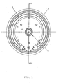
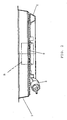
- Figures 1 and 2 show an underfloor heater for closing an opening in or forming the base of a liquid heating vessel.
- the heater comprises a dish-shaped stainless steel base plate 2. This is shown as having a flat lip at its periphery although equally it could be provided with an upwardly open peripheral channel in accordance with the Applicant's Sure Seal system which is described in further detail in WO 96/18331 .
- an aluminium diffuser plate 4 On the underside of the base plate 2 is an aluminium diffuser plate 4.
- An annular sheathed heating element 6 of well known type is brazed to the diffuser plate 4 at its periphery. This will typically be rated at between 2.2 and 3 kilowatts.
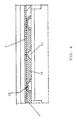
- the aluminium diffuser plate 4 has a circular hole inside which is defined a sensing region 8 which will be described in greater detail below with reference to Figure 3 .
- the base plate 2 Radially inwardly of the hole at the centre of the diffuser plate 4, the base plate 2 is formed with an annular channel 10 on its wet face which forms a corresponding annular wall 12 on the underside of the plate.
- the annular wall 12 defines inside it the circular sensing region 8 which is provided with a second separate diffuser portion comprising a disc of aluminium 14 of the same thickness as the main diffuser plate 4 brazed to the underside of the base plate 2.
- a recess which is shaped to receive a thermal sensor, for example a thermistor.
- a control unit may be mounted to the underside of the heater so that a thermal sensor, e.g. a thermistor, is received against the recess 16 of the sensing region 8.
- a thermal sensor e.g. a thermistor
- the thermal sensor need not be part of an integrated control unit but could be a separate component.
- the vessel In use the vessel is filled with water and the element 6 is energised to heat the water.
- the temperature of the main diffuser plate 4 will be a function of both the temperature of the element 6 and of the liquid inside the vessel.
- the degree of influence of the element temperature upon the temperature of the surface of the main diffuser plate 4 will be dependent upon the distance from the element.
- the temperature of the central diffuser portion 14 in the sensing region pad 14, and thus the temperature seen by the thermal sensor, will be predominantly influenced by the temperature of the water in the vessel since there is a relatively short thermal path through the thin stainless steel base plate 2.
- a sensor placed against the recess 16 can accurately measure the temperature of the water and thereby signal the control to stop heating or reduce the power when a predetermined temperature is reached e.g. 80-85° which is considered the ideal temperature for brewing coffee.
- FIG. 4 A further embodiment of the invention is shown in Figure 4 .
- the base plate 2' does not have an annular channel as in the first embodiment but rather the main central region of the base plate is flat. Instead, a separate annular ring member 18 is initially welded to the underside of the base plate 2' and therefore performs the same function as the annular wall 12 in the first embodiment - namely to locate the central aluminium disc 14 during manufacture and also to act as a thermal barrier between the central aluminium disc 14 as the main diffuser plate 4. In all other respects this embodiment is the same as the previous one.
Abstract
Description
- This invention relates to underfloor heaters which are arranged to form or close an opening in the base of a liquid heating vessel.
- Underfloor heaters for liquid heating vessels are well known and may be divided generally into two categories: sheathed heaters, which have a sheathed resistance element mounted to or formed on the underside of a metal base plate; and thick film heaters which comprise a printed resistance track on the underside of the base plate. In both cases it is conventional to provide an aluminium diffuser plate between the heating element/track and the base plate itself which is usually of stainless steel. Such a diffuser plate serves several functions, an important one of which is to conduct heat from the element to a thermally responsive sensor in order that overheating caused, for example, by operating the heater without any liquid in the vessel, may be sensed quickly and action taken to switch off the heater.
- In some applications however, it is desirable to use a thermal sensor to measure the temperature of liquid in the vessel through the heated base. This might, for example, be done in order to heat the liquid to or maintain it at a temperature below boiling. An example of a control arrangement which is designed to do just that is the Applicant's U19 series of controls described in
EP-A-1233649 . In that document there is disclosed the idea of providing apertures in the diffuser plate between the element and the thermal sensor in order at least partially to decouple the thermal sensor from the direct influence of the heating element, thereby allowing it better to follow the temperature of the liquid in the vessel. - The Applicant has realised that whilst this arrangement is indeed effective it cannot give complete isolation of the sensor from the heater since there must always be part of the diffuser plate which connects the location of the sensor to the heating element.
- It is an object of the present invention to improve upon or at least provide an alternative to such arrangements and thus when viewed from a first aspect the invention provides an underfloor heater for a liquid heating vessel comprising a base plate, a heat diffuser portion in good thermal contact with the base plate, a heating element in good thermal contact with the diffuser portion and a sensing region for receiving a thermal sensor wherein said sensing region is not directly connected to the diffuser portion and is at least partly surrounded by a wall.
- Thus it will be seen by those skilled in the art that in accordance with the invention the sensing region is thermally isolated from the element since it is not connected to the diffuser portion. The sensing region need not have a diffuser portion or the like so that the thermal sensor is arranged to bear directly on to the base plate. However, it is preferred to provide a second heat diffuser portion between the thermal sensor and the base plate. This could be of any suitable material or construction but is preferably of similar characteristics - such as thickness and/or material - to the main heat diffuser portion. Having a diffuser portion in the sensing region is advantageous since it increases the heat capacity of the sensing region which permits better thermal sensing and provides a mechanical 'filter' of the temperature signal. Additionally where, as is preferred, the heat diffuser portion in at least the sensing region is of aluminium, more intimate mating of the thermal sensor can be achieved since aluminium is softer than stainless steel of which the base plate is typically made.
- Simply having a separate 'island' diffuser portion not connected to the main diffuser portion would give rise to significant manufacturing difficulties since the two portions of diffuser material would need to be located and held in place during brazing. However, the wall which partly or fully surrounds the sensing region enables the second diffuser portion in the sensing region to be held in place during brazing.
- This concept is novel and inventive in its own right and thus when viewed from a second aspect the invention provides an underfloor heater for a liquid heating vessel comprising a base plate, a main heat diffuser portion in good thermal contact with the base plate, a heating element in good thermal contact with the main diffuser portion and a sensing region for receiving a thermal sensor wherein said sensing region comprises a second, separate diffuser portion and one or more locating means for locating said second diffuser portion.
- When viewed from a further aspect the invention provides a method of making an underfloor heater comprising providing a base plate with locating means at least partially surrounding a sensing region thereof and attaching two separate heat diffuser portions to said base plate, one of said portion being provided in the sensing region and located therein by the locating means.
- The locating means could comprise a series of discrete formations or projections on the base plate spaced around the periphery of the sensing region but preferably the locating means comprises a continuous wall partly, or more preferably completely, surrounding the sensing region - i.e. in accordance with the first aspect of the invention.
- In accordance with any preceding aspect of the invention the wall could itself be attached to the base plate e.g. by soldering, welding or brazing etc, but in particularly preferred embodiments the wall is provided by forming a channel in the upper, liquid facing side of the base plate. This not only allows the heater to be manufactured conveniently and without requiring a separate part, but the Applicant has also appreciated that since the channel will fill with the liquid being heated during use, it will further enhance the thermal isolation of the sensing region from the heating element and the thermal coupling of the sensing region to the liquid.
- As mentioned above, in at least some embodiments of the invention the heating element comprises a sheathed resistance element. The sheathed element could be provided on the main diffuser portion so that the latter is sandwiched between the element and the base plate, or alternatively the element could be provided directly on the base plate whilst also being in good thermal contact with the diffuser plate e.g. by means of an edge thereof.
- The sensing region may be on any convenient part of the heater and the location may be dictated by design constraints imposed by a corresponding control unit. Preferably however it is located substantially centrally on the base plate. This is beneficial where a sheathed heating element is provided around the periphery of the plate as the centre is then one of the parts of the which receive least heat. This further enhances the thermal isolation of the sensing region from the heating element.
- The invention extends to an assembly comprising an underfloor heater as described herein and a control arrangement comprising a thermal sensor wherein the thermal sensor is arranged in good thermal contact with the sensing region. The invention also extends to a liquid heating vessel including such an assembly.
- Certain embodiments of the present invention will now be described, by way of example only, with reference to the accompanying drawings in which:
-
Fig. 1 is a bottom elevation of an underfloor heater in accordance with the present invention; -
Fig. 2 is a section on line AA ofFig. 1 ; -
Fig. 3 is an enlarged view of part of the section ofFig. 2 marked B ; and -
Fig. 4 is a view similar toFig. 3 of a second embodiment of the invention. -
Figures 1 and2 show an underfloor heater for closing an opening in or forming the base of a liquid heating vessel. The heater comprises a dish-shaped stainlesssteel base plate 2. This is shown as having a flat lip at its periphery although equally it could be provided with an upwardly open peripheral channel in accordance with the Applicant's Sure Seal system which is described in further detail inWO 96/18331 - On the underside of the
base plate 2 is analuminium diffuser plate 4. An annularsheathed heating element 6 of well known type is brazed to thediffuser plate 4 at its periphery. This will typically be rated at between 2.2 and 3 kilowatts. - At the centre of the heater the
aluminium diffuser plate 4 has a circular hole inside which is defined asensing region 8 which will be described in greater detail below with reference toFigure 3 . - Radially inwardly of the hole at the centre of the
diffuser plate 4, thebase plate 2 is formed with anannular channel 10 on its wet face which forms a correspondingannular wall 12 on the underside of the plate. Theannular wall 12 defines inside it thecircular sensing region 8 which is provided with a second separate diffuser portion comprising a disc ofaluminium 14 of the same thickness as themain diffuser plate 4 brazed to the underside of thebase plate 2. - In the centre of the
aluminium disc 14 is a recess which is shaped to receive a thermal sensor, for example a thermistor. - A control unit (not shown) may be mounted to the underside of the heater so that a thermal sensor, e.g. a thermistor, is received against the
recess 16 of thesensing region 8. Of course the thermal sensor need not be part of an integrated control unit but could be a separate component. - In use the vessel is filled with water and the
element 6 is energised to heat the water. The temperature of themain diffuser plate 4 will be a function of both the temperature of theelement 6 and of the liquid inside the vessel. The degree of influence of the element temperature upon the temperature of the surface of themain diffuser plate 4 will be dependent upon the distance from the element. - However, the temperature of the
central diffuser portion 14 in thesensing region pad 14, and thus the temperature seen by the thermal sensor, will be predominantly influenced by the temperature of the water in the vessel since there is a relatively short thermal path through the thin stainlesssteel base plate 2. There is no direct connection between thesensing pad 14 and themain diffuser plate 4 and indeed the water in thechannel 10; and thewall 12; both act as thermal barriers. This means that a sensor placed against therecess 16 can accurately measure the temperature of the water and thereby signal the control to stop heating or reduce the power when a predetermined temperature is reached e.g. 80-85° which is considered the ideal temperature for brewing coffee. - Of course there may be other reasons why it would be desirable to measure the temperature of the liquid in the vessel - for example to measure the rate of change thereof accurately to determine the volume, whether the water is approaching boiling etc.
- A further embodiment of the invention is shown in
Figure 4 . In this embodiment the base plate 2' does not have an annular channel as in the first embodiment but rather the main central region of the base plate is flat. Instead, a separateannular ring member 18 is initially welded to the underside of the base plate 2' and therefore performs the same function as theannular wall 12 in the first embodiment - namely to locate thecentral aluminium disc 14 during manufacture and also to act as a thermal barrier between thecentral aluminium disc 14 as themain diffuser plate 4. In all other respects this embodiment is the same as the previous one. - It will be appreciated by those skilled in the art that the embodiments described are merely examples of how the invention may be put into practice and many modifications and variation therefrom are possible within the scope of the invention. For example, it is not applicable only to sheathed element heaters but can also be applied to thick film heaters. Furthermore, it is not essential for a continuous annular wall to be provided instead it may extend only part way around the sensing region; could be a shape other than circular or arcuate; or could comprise a series of discrete features or protrusions rather than a continuous wall.
Claims (15)
- An underfloor heater for a liquid heating vessel comprising a base plate (2), a heat diffuser portion (4) in good thermal contact with the base plate (2), a heating element (6) in good thermal contact with the diffuser portion (4) and a sensing region (8) for receiving a thermal sensor wherein said sensing region (8) is not directly connected to the diffuser portion (4) and is at least partly surrounded by a wall.
- An underfloor heater as claimed in claim 1 wherein a second heat diffuser portion (14) is provided between the thermal sensor and the base plate (2).
- An underfloor heater as claimed in claim 1 or 2 wherein said second heat diffuser portion (14) is of similar characteristics to the main heat diffuser portion (4).
- An underfloor heater as claimed in claim 1, 2 or 3 wherein said second heat diffuser portion (14) is of aluminium.
- An underfloor heater for a liquid heating vessel comprising a base plate (2), a main heat diffuser portion (4) in good thermal contact with the base plate (2), a heating element (6) in good thermal contact with the main diffuser portion (4) and a sensing region (8) for receiving a thermal sensor wherein said sensing region (8) comprises a second, separate diffuser portion (14) and one or more locating means for locating said second diffuser portion (14).
- An underfloor heater as claimed in claim 5 wherein the locating means comprises a continuous wall (12) at least partly surrounding the sensing region (8).
- An underfloor heater as claimed in any preceding claim wherein the wall (12) is attached as a separate part to the base plate (2).
- An underfloor heater as claimed in any preceding claim wherein the heating element (6) comprises a sheathed resistance element.
- An underfloor heater as claimed in any preceding claim wherein the sensing region (8) is located substantially centrally on the base plate (2).
- An assembly comprising an underfloor heater as claimed in any preceding claim and a control arrangement comprising a thermal sensor wherein the thermal sensor is arranged in good thermal contact with the sensing region (8).
- A liquid heating vessel comprising an assembly as claimed in claim 10.
- A method of making an underfloor heater comprising providing a base plate (2) with locating means at least partially surrounding a sensing region (8) thereof and attaching two separate heat diffuser portions (4,14) to said base plate (2), one of said portions (14) being provided in the sensing region (8) and located therein by the locating means.
- A method as claimed in claim 12 comprising providing a continuous wall (12) at least partly surrounding the sensing region.
- A method as claimed in claim 12 comprising providing a continuous wall (12) completely surrounding the sensing region.
- A method as claimed in claim 13 or 14 comprising attaching a wall (12) as a separate part to the base plate (2).
Priority Applications (1)
| Application Number | Priority Date | Filing Date | Title |
|---|---|---|---|
| PL10180451T PL2363049T3 (en) | 2005-09-09 | 2006-09-04 | Heaters for liquid heating vessels |
Applications Claiming Priority (2)
| Application Number | Priority Date | Filing Date | Title |
|---|---|---|---|
| GBGB0518338.9A GB0518338D0 (en) | 2005-09-09 | 2005-09-09 | Heaters for liquid heating vessels |
| EP06254595.9A EP1762161B1 (en) | 2005-09-09 | 2006-09-04 | Liquid heating vessels |
Related Parent Applications (3)
| Application Number | Title | Priority Date | Filing Date |
|---|---|---|---|
| EP06254595.9 Division | 2006-09-04 | ||
| EP06254595.9A Division EP1762161B1 (en) | 2005-09-09 | 2006-09-04 | Liquid heating vessels |
| EP06254595.9A Division-Into EP1762161B1 (en) | 2005-09-09 | 2006-09-04 | Liquid heating vessels |
Publications (3)
| Publication Number | Publication Date |
|---|---|
| EP2363049A2 true EP2363049A2 (en) | 2011-09-07 |
| EP2363049A3 EP2363049A3 (en) | 2011-12-21 |
| EP2363049B1 EP2363049B1 (en) | 2014-12-03 |
Family
ID=35221127
Family Applications (2)
| Application Number | Title | Priority Date | Filing Date |
|---|---|---|---|
| EP06254595.9A Active EP1762161B1 (en) | 2005-09-09 | 2006-09-04 | Liquid heating vessels |
| EP10180451.6A Active EP2363049B1 (en) | 2005-09-09 | 2006-09-04 | Heaters for liquid heating vessels |
Family Applications Before (1)
| Application Number | Title | Priority Date | Filing Date |
|---|---|---|---|
| EP06254595.9A Active EP1762161B1 (en) | 2005-09-09 | 2006-09-04 | Liquid heating vessels |
Country Status (4)
| Country | Link |
|---|---|
| EP (2) | EP1762161B1 (en) |
| CN (2) | CN104257263B (en) |
| GB (1) | GB0518338D0 (en) |
| PL (2) | PL2363049T3 (en) |
Families Citing this family (6)
| Publication number | Priority date | Publication date | Assignee | Title |
|---|---|---|---|---|
| US8097834B2 (en) | 2007-06-28 | 2012-01-17 | Strix Limited | Liquid heating vessels |
| US7783176B2 (en) | 2007-06-28 | 2010-08-24 | Strix Limited | Heaters for liquid heating vessels |
| AU2010200571B2 (en) * | 2009-02-16 | 2016-04-21 | Newell Australia Pty Ltd | Improved temperature sensor for an electric heating appliance |
| GB0919331D0 (en) | 2009-11-04 | 2009-12-23 | Strix Ltd | Cordless electrical appliances |
| CN107811518A (en) * | 2016-09-14 | 2018-03-20 | 浙江苏泊尔家电制造有限公司 | Temperature-sensing device and cooking apparatus |
| US10429079B2 (en) * | 2017-02-21 | 2019-10-01 | Zoppas Industries De Mexico S.A., De C.V. | Electric stovetop heater unit with integrated temperature control |
Citations (2)
| Publication number | Priority date | Publication date | Assignee | Title |
|---|---|---|---|---|
| WO1996018331A1 (en) | 1994-12-13 | 1996-06-20 | Strix Limited | Liquid heating vessels |
| EP1233649A1 (en) | 2001-02-19 | 2002-08-21 | Strix Limited | Thermally sensitive control for a liquid heating vessel |
Family Cites Families (14)
| Publication number | Priority date | Publication date | Assignee | Title |
|---|---|---|---|---|
| GB522609A (en) * | 1938-12-12 | 1940-06-21 | Gen Electric Co Ltd | Improvements in and relating to electric heating devices |
| DE3223417A1 (en) * | 1982-06-23 | 1983-12-29 | Karl 7519 Oberderdingen Fischer | ELECTRIC COOKING PLATE |
| CA1202659A (en) * | 1984-06-07 | 1986-04-01 | Ronal C. Du Pont | Electric kettle |
| DE3530403A1 (en) * | 1985-04-06 | 1986-10-16 | Philips Patentverwaltung | METHOD FOR AUTOMATICALLY REGULATING THE COOKING HEATING PROCESS OF A COOKING DEVICE |
| US4717822A (en) * | 1986-08-04 | 1988-01-05 | Hughes Aircraft Company | Rosette scanning surveillance sensor |
| JPH0815457B2 (en) * | 1993-06-30 | 1996-02-21 | タイガー魔法瓶株式会社 | Electric water heater |
| US6153859A (en) | 1995-07-31 | 2000-11-28 | Strix Limited | Liquid heating vessels |
| FR2810526B1 (en) * | 2000-06-27 | 2002-11-29 | Seb Sa | HEATING CONTAINER FOR HOUSEHOLD APPLIANCES LIQUID HEATERS |
| DE10131995B4 (en) * | 2001-03-07 | 2008-07-03 | Eichenauer Heizelemente Gmbh & Co. Kg | Heating insert for an electrically heated cooking vessel |
| GB2377608B (en) | 2001-04-23 | 2005-09-07 | Strix Ltd | Electric heaters |
| JP2003180524A (en) * | 2001-12-19 | 2003-07-02 | Matsushita Electric Ind Co Ltd | Electric hot-water heater |
| JP2003279157A (en) * | 2002-03-22 | 2003-10-02 | Toto Ltd | Preventive mechanism for excessive temperature rise in resin container to heat fluid |
| GB2399735B (en) | 2003-03-25 | 2006-04-26 | Strix Ltd | Electric liquid boiling appliances |
| US6834160B1 (en) * | 2003-11-14 | 2004-12-21 | Huang Chen-Lung | Electric heater with a sensor preventing no-water heating |
-
2005
- 2005-09-09 GB GBGB0518338.9A patent/GB0518338D0/en not_active Ceased
-
2006
- 2006-09-04 PL PL10180451T patent/PL2363049T3/en unknown
- 2006-09-04 EP EP06254595.9A patent/EP1762161B1/en active Active
- 2006-09-04 PL PL06254595T patent/PL1762161T3/en unknown
- 2006-09-04 EP EP10180451.6A patent/EP2363049B1/en active Active
- 2006-09-08 CN CN201410412053.4A patent/CN104257263B/en active Active
- 2006-09-08 CN CN200610135704.5A patent/CN1927102B/en active Active
Patent Citations (2)
| Publication number | Priority date | Publication date | Assignee | Title |
|---|---|---|---|---|
| WO1996018331A1 (en) | 1994-12-13 | 1996-06-20 | Strix Limited | Liquid heating vessels |
| EP1233649A1 (en) | 2001-02-19 | 2002-08-21 | Strix Limited | Thermally sensitive control for a liquid heating vessel |
Also Published As
| Publication number | Publication date |
|---|---|
| CN104257263B (en) | 2017-10-24 |
| EP2363049A3 (en) | 2011-12-21 |
| PL1762161T3 (en) | 2014-12-31 |
| EP2363049B1 (en) | 2014-12-03 |
| CN104257263A (en) | 2015-01-07 |
| GB0518338D0 (en) | 2005-10-19 |
| EP1762161B1 (en) | 2014-06-25 |
| EP1762161A1 (en) | 2007-03-14 |
| CN1927102A (en) | 2007-03-14 |
| PL2363049T3 (en) | 2015-06-30 |
| CN1927102B (en) | 2021-06-18 |
Similar Documents
| Publication | Publication Date | Title |
|---|---|---|
| EP0734215B1 (en) | Apparatus for heating liquids | |
| EP2363049B1 (en) | Heaters for liquid heating vessels | |
| AU2008101189B4 (en) | Improved temperature sensor for an electric heating appliance | |
| AU2009101273B4 (en) | Improved temperature sensor for an electric kettle | |
| RU2138136C1 (en) | Electric heating container to boil water | |
| US8299405B2 (en) | Household appliance for heating liquid | |
| KR100297066B1 (en) | Septic period | |
| EP2552288B1 (en) | Beverage dispensing machine | |
| US7783176B2 (en) | Heaters for liquid heating vessels | |
| EP1381299B1 (en) | Electric heaters | |
| JPH07307196A (en) | Temperature detector for microwave oven | |
| EP1462039B1 (en) | Electric liquid boiling apparatus | |
| AU2015224376B2 (en) | Heating vessel with noise reduction | |
| JP2002102062A (en) | Heating and heat-retaining unit for selling stewed food | |
| AU2012265568B2 (en) | Improved temperature sensor for an electric kettle | |
| AU2010200571B2 (en) | Improved temperature sensor for an electric heating appliance | |
| CN212037149U (en) | Cooking utensil | |
| EP3989782B1 (en) | Temperature sensor fitting | |
| GB2052226A (en) | Improvements In or Relating To Electric Kettles | |
| EP1639921B1 (en) | Electric liquid boiling appliances | |
| JPS6330888Y2 (en) | ||
| KR200186603Y1 (en) | Thermo-sensitive switch device for electric heater |
Legal Events
| Date | Code | Title | Description |
|---|---|---|---|
| PUAI | Public reference made under article 153(3) epc to a published international application that has entered the european phase |
Free format text: ORIGINAL CODE: 0009012 |
|
| AC | Divisional application: reference to earlier application |
Ref document number: 1762161 Country of ref document: EP Kind code of ref document: P |
|
| AK | Designated contracting states |
Kind code of ref document: A2 Designated state(s): AT BE BG CH CY CZ DE DK EE ES FI FR GB GR HU IE IS IT LI LT LU LV MC NL PL PT RO SE SI SK TR |
|
| PUAL | Search report despatched |
Free format text: ORIGINAL CODE: 0009013 |
|
| AK | Designated contracting states |
Kind code of ref document: A3 Designated state(s): AT BE BG CH CY CZ DE DK EE ES FI FR GB GR HU IE IS IT LI LT LU LV MC NL PL PT RO SE SI SK TR |
|
| RIC1 | Information provided on ipc code assigned before grant |
Ipc: A47J 27/21 20060101AFI20111116BHEP |
|
| 17P | Request for examination filed |
Effective date: 20120619 |
|
| GRAP | Despatch of communication of intention to grant a patent |
Free format text: ORIGINAL CODE: EPIDOSNIGR1 |
|
| INTG | Intention to grant announced |
Effective date: 20140711 |
|
| GRAS | Grant fee paid |
Free format text: ORIGINAL CODE: EPIDOSNIGR3 |
|
| GRAA | (expected) grant |
Free format text: ORIGINAL CODE: 0009210 |
|
| AC | Divisional application: reference to earlier application |
Ref document number: 1762161 Country of ref document: EP Kind code of ref document: P |
|
| AK | Designated contracting states |
Kind code of ref document: B1 Designated state(s): AT BE BG CH CY CZ DE DK EE ES FI FR GB GR HU IE IS IT LI LT LU LV MC NL PL PT RO SE SI SK TR |
|
| REG | Reference to a national code |
Ref country code: GB Ref legal event code: FG4D |
|
| REG | Reference to a national code |
Ref country code: AT Ref legal event code: REF Ref document number: 698844 Country of ref document: AT Kind code of ref document: T Effective date: 20141215 Ref country code: CH Ref legal event code: EP |
|
| REG | Reference to a national code |
Ref country code: IE Ref legal event code: FG4D |
|
| REG | Reference to a national code |
Ref country code: DE Ref legal event code: R096 Ref document number: 602006043929 Country of ref document: DE Effective date: 20150115 |
|
| REG | Reference to a national code |
Ref country code: NL Ref legal event code: T3 |
|
| REG | Reference to a national code |
Ref country code: AT Ref legal event code: MK05 Ref document number: 698844 Country of ref document: AT Kind code of ref document: T Effective date: 20141203 |
|
| PG25 | Lapsed in a contracting state [announced via postgrant information from national office to epo] |
Ref country code: ES Free format text: LAPSE BECAUSE OF FAILURE TO SUBMIT A TRANSLATION OF THE DESCRIPTION OR TO PAY THE FEE WITHIN THE PRESCRIBED TIME-LIMIT Effective date: 20141203 Ref country code: LT Free format text: LAPSE BECAUSE OF FAILURE TO SUBMIT A TRANSLATION OF THE DESCRIPTION OR TO PAY THE FEE WITHIN THE PRESCRIBED TIME-LIMIT Effective date: 20141203 Ref country code: FI Free format text: LAPSE BECAUSE OF FAILURE TO SUBMIT A TRANSLATION OF THE DESCRIPTION OR TO PAY THE FEE WITHIN THE PRESCRIBED TIME-LIMIT Effective date: 20141203 |
|
| REG | Reference to a national code |
Ref country code: LT Ref legal event code: MG4D |
|
| PG25 | Lapsed in a contracting state [announced via postgrant information from national office to epo] |
Ref country code: LV Free format text: LAPSE BECAUSE OF FAILURE TO SUBMIT A TRANSLATION OF THE DESCRIPTION OR TO PAY THE FEE WITHIN THE PRESCRIBED TIME-LIMIT Effective date: 20141203 Ref country code: CY Free format text: LAPSE BECAUSE OF FAILURE TO SUBMIT A TRANSLATION OF THE DESCRIPTION OR TO PAY THE FEE WITHIN THE PRESCRIBED TIME-LIMIT Effective date: 20141203 Ref country code: GR Free format text: LAPSE BECAUSE OF FAILURE TO SUBMIT A TRANSLATION OF THE DESCRIPTION OR TO PAY THE FEE WITHIN THE PRESCRIBED TIME-LIMIT Effective date: 20150304 Ref country code: SE Free format text: LAPSE BECAUSE OF FAILURE TO SUBMIT A TRANSLATION OF THE DESCRIPTION OR TO PAY THE FEE WITHIN THE PRESCRIBED TIME-LIMIT Effective date: 20141203 Ref country code: AT Free format text: LAPSE BECAUSE OF FAILURE TO SUBMIT A TRANSLATION OF THE DESCRIPTION OR TO PAY THE FEE WITHIN THE PRESCRIBED TIME-LIMIT Effective date: 20141203 |
|
| REG | Reference to a national code |
Ref country code: PL Ref legal event code: T3 |
|
| PG25 | Lapsed in a contracting state [announced via postgrant information from national office to epo] |
Ref country code: RO Free format text: LAPSE BECAUSE OF FAILURE TO SUBMIT A TRANSLATION OF THE DESCRIPTION OR TO PAY THE FEE WITHIN THE PRESCRIBED TIME-LIMIT Effective date: 20141203 Ref country code: SK Free format text: LAPSE BECAUSE OF FAILURE TO SUBMIT A TRANSLATION OF THE DESCRIPTION OR TO PAY THE FEE WITHIN THE PRESCRIBED TIME-LIMIT Effective date: 20141203 Ref country code: PT Free format text: LAPSE BECAUSE OF FAILURE TO SUBMIT A TRANSLATION OF THE DESCRIPTION OR TO PAY THE FEE WITHIN THE PRESCRIBED TIME-LIMIT Effective date: 20150403 Ref country code: EE Free format text: LAPSE BECAUSE OF FAILURE TO SUBMIT A TRANSLATION OF THE DESCRIPTION OR TO PAY THE FEE WITHIN THE PRESCRIBED TIME-LIMIT Effective date: 20141203 Ref country code: CZ Free format text: LAPSE BECAUSE OF FAILURE TO SUBMIT A TRANSLATION OF THE DESCRIPTION OR TO PAY THE FEE WITHIN THE PRESCRIBED TIME-LIMIT Effective date: 20141203 |
|
| PG25 | Lapsed in a contracting state [announced via postgrant information from national office to epo] |
Ref country code: IS Free format text: LAPSE BECAUSE OF FAILURE TO SUBMIT A TRANSLATION OF THE DESCRIPTION OR TO PAY THE FEE WITHIN THE PRESCRIBED TIME-LIMIT Effective date: 20150403 |
|
| REG | Reference to a national code |
Ref country code: DE Ref legal event code: R097 Ref document number: 602006043929 Country of ref document: DE |
|
| PLBE | No opposition filed within time limit |
Free format text: ORIGINAL CODE: 0009261 |
|
| STAA | Information on the status of an ep patent application or granted ep patent |
Free format text: STATUS: NO OPPOSITION FILED WITHIN TIME LIMIT |
|
| PG25 | Lapsed in a contracting state [announced via postgrant information from national office to epo] |
Ref country code: DK Free format text: LAPSE BECAUSE OF FAILURE TO SUBMIT A TRANSLATION OF THE DESCRIPTION OR TO PAY THE FEE WITHIN THE PRESCRIBED TIME-LIMIT Effective date: 20141203 |
|
| 26N | No opposition filed |
Effective date: 20150904 |
|
| PG25 | Lapsed in a contracting state [announced via postgrant information from national office to epo] |
Ref country code: IT Free format text: LAPSE BECAUSE OF FAILURE TO SUBMIT A TRANSLATION OF THE DESCRIPTION OR TO PAY THE FEE WITHIN THE PRESCRIBED TIME-LIMIT Effective date: 20141203 |
|
| PG25 | Lapsed in a contracting state [announced via postgrant information from national office to epo] |
Ref country code: SI Free format text: LAPSE BECAUSE OF FAILURE TO SUBMIT A TRANSLATION OF THE DESCRIPTION OR TO PAY THE FEE WITHIN THE PRESCRIBED TIME-LIMIT Effective date: 20141203 |
|
| PG25 | Lapsed in a contracting state [announced via postgrant information from national office to epo] |
Ref country code: MC Free format text: LAPSE BECAUSE OF FAILURE TO SUBMIT A TRANSLATION OF THE DESCRIPTION OR TO PAY THE FEE WITHIN THE PRESCRIBED TIME-LIMIT Effective date: 20141203 Ref country code: LU Free format text: LAPSE BECAUSE OF FAILURE TO SUBMIT A TRANSLATION OF THE DESCRIPTION OR TO PAY THE FEE WITHIN THE PRESCRIBED TIME-LIMIT Effective date: 20150904 |
|
| REG | Reference to a national code |
Ref country code: CH Ref legal event code: PL |
|
| REG | Reference to a national code |
Ref country code: IE Ref legal event code: MM4A |
|
| PG25 | Lapsed in a contracting state [announced via postgrant information from national office to epo] |
Ref country code: CH Free format text: LAPSE BECAUSE OF NON-PAYMENT OF DUE FEES Effective date: 20150930 Ref country code: LI Free format text: LAPSE BECAUSE OF NON-PAYMENT OF DUE FEES Effective date: 20150930 Ref country code: IE Free format text: LAPSE BECAUSE OF NON-PAYMENT OF DUE FEES Effective date: 20150904 |
|
| REG | Reference to a national code |
Ref country code: FR Ref legal event code: PLFP Year of fee payment: 11 |
|
| PG25 | Lapsed in a contracting state [announced via postgrant information from national office to epo] |
Ref country code: HU Free format text: LAPSE BECAUSE OF FAILURE TO SUBMIT A TRANSLATION OF THE DESCRIPTION OR TO PAY THE FEE WITHIN THE PRESCRIBED TIME-LIMIT; INVALID AB INITIO Effective date: 20060904 Ref country code: BG Free format text: LAPSE BECAUSE OF FAILURE TO SUBMIT A TRANSLATION OF THE DESCRIPTION OR TO PAY THE FEE WITHIN THE PRESCRIBED TIME-LIMIT Effective date: 20141203 |
|
| REG | Reference to a national code |
Ref country code: FR Ref legal event code: PLFP Year of fee payment: 12 |
|
| REG | Reference to a national code |
Ref country code: FR Ref legal event code: PLFP Year of fee payment: 13 |
|
| PGFP | Annual fee paid to national office [announced via postgrant information from national office to epo] |
Ref country code: IT Payment date: 20180731 Year of fee payment: 4 |
|
| PGFP | Annual fee paid to national office [announced via postgrant information from national office to epo] |
Ref country code: PL Payment date: 20180824 Year of fee payment: 13 Ref country code: NL Payment date: 20180917 Year of fee payment: 13 |
|
| REG | Reference to a national code |
Ref country code: NL Ref legal event code: MM Effective date: 20191001 |
|
| PG25 | Lapsed in a contracting state [announced via postgrant information from national office to epo] |
Ref country code: NL Free format text: LAPSE BECAUSE OF NON-PAYMENT OF DUE FEES Effective date: 20191001 |
|
| REG | Reference to a national code |
Ref country code: BE Ref legal event code: MM Effective date: 20190930 |
|
| PG25 | Lapsed in a contracting state [announced via postgrant information from national office to epo] |
Ref country code: BE Free format text: LAPSE BECAUSE OF NON-PAYMENT OF DUE FEES Effective date: 20190930 |
|
| PG25 | Lapsed in a contracting state [announced via postgrant information from national office to epo] |
Ref country code: FR Free format text: LAPSE BECAUSE OF NON-PAYMENT OF DUE FEES Effective date: 20190930 |
|
| REG | Reference to a national code |
Ref country code: DE Ref legal event code: R082 Ref document number: 602006043929 Country of ref document: DE |
|
| PGFP | Annual fee paid to national office [announced via postgrant information from national office to epo] |
Ref country code: GB Payment date: 20210920 Year of fee payment: 16 Ref country code: TR Payment date: 20210901 Year of fee payment: 16 Ref country code: DE Payment date: 20210921 Year of fee payment: 16 |
|
| PG25 | Lapsed in a contracting state [announced via postgrant information from national office to epo] |
Ref country code: PL Free format text: LAPSE BECAUSE OF NON-PAYMENT OF DUE FEES Effective date: 20190904 |
|
| REG | Reference to a national code |
Ref country code: DE Ref legal event code: R119 Ref document number: 602006043929 Country of ref document: DE |
|
| GBPC | Gb: european patent ceased through non-payment of renewal fee |
Effective date: 20220904 |
|
| PG25 | Lapsed in a contracting state [announced via postgrant information from national office to epo] |
Ref country code: DE Free format text: LAPSE BECAUSE OF NON-PAYMENT OF DUE FEES Effective date: 20230401 |
|
| PG25 | Lapsed in a contracting state [announced via postgrant information from national office to epo] |
Ref country code: GB Free format text: LAPSE BECAUSE OF NON-PAYMENT OF DUE FEES Effective date: 20220904 |